60
GE Measurement & Control Eddy Current 021-002-597 Rev. 2 September 2012 Apollo™ TSB Operating Manual

GEMeasurement & Control Eddy Current
Apollo™ TSB Operating Manual
021-002-597 Rev. 2September 2012


Apollo™ TSBInspection Management System
Operating Manual
021-002-597 Rev. 2September 2012
www.ge-mcs.com
©2012 General Electric Company. All rights reserved.Technical content subject to change without notice.

[no content intended for this page - proceed to next page]
ii

Contents
Safety and Warranty Information
Safety Information . . . . . . . . . . . . . . . . . . . . . . . . . . . . . . . . . . . . . . . . . . . . . . . . . . . . . . . . . . . . . . . . . . . . . . . . . . v
Software . . . . . . . . . . . . . . . . . . . . . . . . . . . . . . . . . . . . . . . . . . . . . . . . . . . . . . . . . . . . . . . . . . . . . . . . . . . . . . . . . . v
Defects/Errors and Exceptional Stresses . . . . . . . . . . . . . . . . . . . . . . . . . . . . . . . . . . . . . . . . . . . . . . . . . . . . . . . . . v
Important Information on Eddy Current Testing . . . . . . . . . . . . . . . . . . . . . . . . . . . . . . . . . . . . . . . . . . . . . . . . . . . v
Pre-Conditions for Testing with Eddy Current Testing . . . . . . . . . . . . . . . . . . . . . . . . . . . . . . . . . . . . . . . . . . . . . . v
Operator Training. . . . . . . . . . . . . . . . . . . . . . . . . . . . . . . . . . . . . . . . . . . . . . . . . . . . . . . . . . . . . . . . . . . . . . . . . . vi
Warranty. . . . . . . . . . . . . . . . . . . . . . . . . . . . . . . . . . . . . . . . . . . . . . . . . . . . . . . . . . . . . . . . . . . . . . . . . . . . . . . . . vi
Chapter 1. Introduction
Chapter 2. Main Screen
Chapter 3. File Menu
3.1 New Model. . . . . . . . . . . . . . . . . . . . . . . . . . . . . . . . . . . . . . . . . . . . . . . . . . . . . . . . . . . . . . . . . . . . . . . . . . . . . . . . 5
3.1.1 Defining Row/Tube and Section Orientation. . . . . . . . . . . . . . . . . . . . . . . . . . . . . . . . . . . . . . . . . . . . . . . 7
3.2 Loading a Model File . . . . . . . . . . . . . . . . . . . . . . . . . . . . . . . . . . . . . . . . . . . . . . . . . . . . . . . . . . . . . . . . . . . . . . . . 9
3.3 Save Model/Save Model As . . . . . . . . . . . . . . . . . . . . . . . . . . . . . . . . . . . . . . . . . . . . . . . . . . . . . . . . . . . . . . . . . 10
3.4 Exit the Application . . . . . . . . . . . . . . . . . . . . . . . . . . . . . . . . . . . . . . . . . . . . . . . . . . . . . . . . . . . . . . . . . . . . . . . 10
Chapter 4. Model Menu
4.1 Model Information . . . . . . . . . . . . . . . . . . . . . . . . . . . . . . . . . . . . . . . . . . . . . . . . . . . . . . . . . . . . . . . . . . . . . . . . 11
4.2 New Section . . . . . . . . . . . . . . . . . . . . . . . . . . . . . . . . . . . . . . . . . . . . . . . . . . . . . . . . . . . . . . . . . . . . . . . . . . . . . . 13
4.3 Editing Sections . . . . . . . . . . . . . . . . . . . . . . . . . . . . . . . . . . . . . . . . . . . . . . . . . . . . . . . . . . . . . . . . . . . . . . . . . . . 16
4.4 Landmarks . . . . . . . . . . . . . . . . . . . . . . . . . . . . . . . . . . . . . . . . . . . . . . . . . . . . . . . . . . . . . . . . . . . . . . . . . . . . . . . 17
4.5 Materials. . . . . . . . . . . . . . . . . . . . . . . . . . . . . . . . . . . . . . . . . . . . . . . . . . . . . . . . . . . . . . . . . . . . . . . . . . . . . . . . . 19
4.6 Symbols . . . . . . . . . . . . . . . . . . . . . . . . . . . . . . . . . . . . . . . . . . . . . . . . . . . . . . . . . . . . . . . . . . . . . . . . . . . . . . . . . 20
4.7 Leg . . . . . . . . . . . . . . . . . . . . . . . . . . . . . . . . . . . . . . . . . . . . . . . . . . . . . . . . . . . . . . . . . . . . . . . . . . . . . . . . . . . . . 21
4.8 Tube Symbol Size . . . . . . . . . . . . . . . . . . . . . . . . . . . . . . . . . . . . . . . . . . . . . . . . . . . . . . . . . . . . . . . . . . . . . . . . . 22
4.9 Set Materials Mode . . . . . . . . . . . . . . . . . . . . . . . . . . . . . . . . . . . . . . . . . . . . . . . . . . . . . . . . . . . . . . . . . . . . . . . . 23
4.10 Printing . . . . . . . . . . . . . . . . . . . . . . . . . . . . . . . . . . . . . . . . . . . . . . . . . . . . . . . . . . . . . . . . . . . . . . . . . . . . . . . . . 24
Apollo™ TSB Operating Manual iii

Contents
Chapter 5. Edit Menu
5.1 Zoom Buttons . . . . . . . . . . . . . . . . . . . . . . . . . . . . . . . . . . . . . . . . . . . . . . . . . . . . . . . . . . . . . . . . . . . . . . . . . . . . .25
5.2 Undo/Redo . . . . . . . . . . . . . . . . . . . . . . . . . . . . . . . . . . . . . . . . . . . . . . . . . . . . . . . . . . . . . . . . . . . . . . . . . . . . . . .25
5.3 Select . . . . . . . . . . . . . . . . . . . . . . . . . . . . . . . . . . . . . . . . . . . . . . . . . . . . . . . . . . . . . . . . . . . . . . . . . . . . . . . . . . .25
5.4 Cut/ Copy/Paste . . . . . . . . . . . . . . . . . . . . . . . . . . . . . . . . . . . . . . . . . . . . . . . . . . . . . . . . . . . . . . . . . . . . . . . . . . .26
5.5 Move. . . . . . . . . . . . . . . . . . . . . . . . . . . . . . . . . . . . . . . . . . . . . . . . . . . . . . . . . . . . . . . . . . . . . . . . . . . . . . . . . . . .27
5.6 Rotate . . . . . . . . . . . . . . . . . . . . . . . . . . . . . . . . . . . . . . . . . . . . . . . . . . . . . . . . . . . . . . . . . . . . . . . . . . . . . . . . . . .28
5.7 Scale . . . . . . . . . . . . . . . . . . . . . . . . . . . . . . . . . . . . . . . . . . . . . . . . . . . . . . . . . . . . . . . . . . . . . . . . . . . . . . . . . . . .28
5.8 Resequencing Tubes . . . . . . . . . . . . . . . . . . . . . . . . . . . . . . . . . . . . . . . . . . . . . . . . . . . . . . . . . . . . . . . . . . . . . . . .28
5.9 Flip . . . . . . . . . . . . . . . . . . . . . . . . . . . . . . . . . . . . . . . . . . . . . . . . . . . . . . . . . . . . . . . . . . . . . . . . . . . . . . . . . . . . .30
5.10 Insert Tube . . . . . . . . . . . . . . . . . . . . . . . . . . . . . . . . . . . . . . . . . . . . . . . . . . . . . . . . . . . . . . . . . . . . . . . . . . . . . . .31
Chapter 6. Texts and Lines Menu
6.1 To Add Text . . . . . . . . . . . . . . . . . . . . . . . . . . . . . . . . . . . . . . . . . . . . . . . . . . . . . . . . . . . . . . . . . . . . . . . . . . . . . .33
6.2 To Add a Line . . . . . . . . . . . . . . . . . . . . . . . . . . . . . . . . . . . . . . . . . . . . . . . . . . . . . . . . . . . . . . . . . . . . . . . . . . . . .33
6.3 Edit Texts and Lines . . . . . . . . . . . . . . . . . . . . . . . . . . . . . . . . . . . . . . . . . . . . . . . . . . . . . . . . . . . . . . . . . . . . . . . .33
6.4 Move Texts and Lines. . . . . . . . . . . . . . . . . . . . . . . . . . . . . . . . . . . . . . . . . . . . . . . . . . . . . . . . . . . . . . . . . . . . . . .33
6.5 Eliminate Texts and Lines . . . . . . . . . . . . . . . . . . . . . . . . . . . . . . . . . . . . . . . . . . . . . . . . . . . . . . . . . . . . . . . . . . .33
Chapter 7. Menu Options
7.1 Graphic Properties . . . . . . . . . . . . . . . . . . . . . . . . . . . . . . . . . . . . . . . . . . . . . . . . . . . . . . . . . . . . . . . . . . . . . . . . .35
7.2 Units of Measurement . . . . . . . . . . . . . . . . . . . . . . . . . . . . . . . . . . . . . . . . . . . . . . . . . . . . . . . . . . . . . . . . . . . . . .36
Chapter 8. About Menu
8.1 Installing the Application . . . . . . . . . . . . . . . . . . . . . . . . . . . . . . . . . . . . . . . . . . . . . . . . . . . . . . . . . . . . . . . . . . . .37
8.1.1 Prerequisites . . . . . . . . . . . . . . . . . . . . . . . . . . . . . . . . . . . . . . . . . . . . . . . . . . . . . . . . . . . . . . . . . . . . . . .37
8.1.2 To Install Apollo.NET . . . . . . . . . . . . . . . . . . . . . . . . . . . . . . . . . . . . . . . . . . . . . . . . . . . . . . . . . . . . . . . .37
Chapter 9. Map Building Tutorial
9.1 Setting Up a New Model . . . . . . . . . . . . . . . . . . . . . . . . . . . . . . . . . . . . . . . . . . . . . . . . . . . . . . . . . . . . . . . . . . . .39
9.1.1 Section Number and Sequencing. . . . . . . . . . . . . . . . . . . . . . . . . . . . . . . . . . . . . . . . . . . . . . . . . . . . . . . .43
9.1.2 Map Editing . . . . . . . . . . . . . . . . . . . . . . . . . . . . . . . . . . . . . . . . . . . . . . . . . . . . . . . . . . . . . . . . . . . . . . . .45
iv Apollo™ TSB Operating Manual

Safety and Warranty Information
Safety and Warranty Information
Safety Information
The Apollo™ was designed and tested in accordance with EN61010 Part 1, 2002 Safety Requirement for Electrical and Measuring, Control and Laboratory Use.
Before powering or operating this instrument, the following safety information should be carefully read. This operating manual should be kept in a safe place for reference.
Software
Software is never completely free from errors. Before using any software controlled test equipment, please make sure that the required functions operate correctly perfectly in the intended combination. If you have any questions about the use of your test equipment, please contact your nearest representative of GE Measurement & Control.
Defects/Errors and Exceptional Stresses
Attention! If you have reason to believe that safe operation of your Apollo is no longer possible, you must disconnect the instrument.
DO NOT OPERATE IF:
• Instrument is visibly damaged.
• Instrument no longer operates correctly.
• Instrument has been stored for a prolonged period in adverse conditions.
• Instrument has been subjected to heavy stresses during transportation.
Important Information on Eddy Current Testing
Please read the following information before using your Apollo. It is important that you understand and utilize this information to avoid any operator errors that might lead to false test results. This could result in personal injuries or damage to property.
Pre-Conditions for Testing with Eddy Current Testing
This operating manual contains essential information on how to operate your test equipment. In addition, there are a number of additional factors that affect test results, which are beyond the scope of this operating manual. This operating manual only covers the most important factors for a safe and reliable Eddy Current inspection, and operator training.
Apollo™ TSB Operating Manual v

Safety and Warranty Information
Operator Training
Attention! If you have reason to believe that safe operation of your Apollo is no longer possible, you must disconnect the instrument.
The operation of an Eddy Current test device requires proper training in Eddy Current test methods and equipment usage.
As a general rule, effective use of eddy current equipment for new applications requires the following:
• An understanding of the principles of Eddy Current testing, particularly aspects which may limit detection of flaws such as depth of penetration and the way in which different probe configurations respond to different flaw types.
• An understanding of other NDT and inspection procedures which may be more appropriate or be required to verify the results.
• Knowledge of the application, i.e. the way in which the part being tested is manufactured or stressed in use and the probable flaw mechanisms.
• A good working knowledge of the equipment to be used plus a written technique to be followed in performing the inspection.
Warranty
Limited Service Warranty:
If, through our negligence, GE Inspection Technologies directly caused physical damage to your equipment while the equipment is in the sole custody and control of GE Inspection Technologies, we shall choose at our opinion either to repair the damage or replace the damaged portion of the equipment at our own expense, or to indemnify and hold you harmless for such physical damage to the Equipment. EXCEPT FOR THE WARRANTY SET IN THIS PARAGRAPH, GEIT EXPRESSLY DISCLAIMS ALL WARRANTIES AND REPRSENTATION OF ANY KIND WITH RESPECT TO OUR SERVICES OR THE INFORMATION CONTAINED IN ANY REPORTS THAT WE ISSUE TO YOU, WHETHER EXPRESSED OR IMPLIED, INCLUDING ANY IMPLIED WARRANTIES OF MERCHANTABILITY, FITNESS FOR A PARTICULAR PURPOSE, NON-IN-FRINGEMENT, TITLE AND WARRANTIES ARISING FROM COURSE OF PERFORMANCE, COURSE OF DEALING OR TRADE USAGE.
vi Apollo™ TSB Operating Manual

Chapter 1. Introduction
Chapter 1. Introduction
The Apollo TSB Tubesheet Builder allows users to create component tube sheet models for later use in the development of test plans to be used in acquisition as well as data management. The model files created in Apollo TSB are stored as XML files, for loading and display in the other Apollo products as well as in the Apollo acquisition software for test plan viewing. Once created, these model files can be edited or modified using numerous available tools: Move, Rotate, Scale and Resequence of tubes. Model files also allow the user the ability to identify tube materials or tubing of the same material but varying wall thicknesses.
In addition to the graphical layout of the tubes, the user can manage all information related to the map, tube support plates, materials, symbols, etc. The tubes can be identified independently or in sections of tubes. Resequencing of tubes uses the following options.
Axis—determines the direction of the tubes to be resequenced.
Action— determines the type of resequencing to be achieved.
Resequence as—provides the following options, Numeric, Alpha, Alpha Numeric, and Numeric Alpha.
Sequencing—determines the direction of the tubes to be resequenced. Top to Bottom or Bottom to Top are the two available options.
Starting— determines the tube number at which the resequence function will start.
Shift by— allows the user to shift select tube numbers by whichever number is selected.
Assign—allows the user to assign a specific tube number to a tube symbol.
Figure 1: Resequence Selection Window
User can easily resequence single tube and multiple tubes in a group or section.
Apollo™ TSB Operating Manual 1

Chapter 1. Introduction
For better comprehension of the model file and tube layout, it is possible to assign lines and text to the map aiding users with identifying features such as quadrant numbers, the location of the first row in a section (Row 1 Tube 1), etc.
This manual outlines all the options for the TSB application and is a useful tool for designing component models.
2 Apollo™ TSB Operating Manual

Chapter 2. Main Screen
Chapter 2. Main Screen
The Main screen of the TSB application consists of three fundamental parts:
• Direct access buttons: This set of buttons provides access to many common operations such as:
• Landmarks
• Materials
• Symbols
• Zoom/Unzoom
• Do/Undo
• Save/Store
• Inlet/Outlet
• Design Screen: The design screen shows the working model, where the user will be able to interact and modify the map, performing such functions as tube selection, add/delete tubes, modify sections, assign materials, etc.
• Status Bar: The status bar is located at the bottom of the application screen. When moving the mouse over a tube symbol on the map, the status bar automatically updates, providing the user with applicable information about the tube under the mouse position. This information includes zone, section, row and tube numbering, as well as number of tubes selected when performing editing functions.
Apollo™ TSB Operating Manual 3

Chapter 2. Main Screen
[no content intended for this page - proceed to next page]
4 Apollo™ TSB Operating Manual

Chapter 3. File Menu
Chapter 3. File Menu
The File menu allows the user to create a New Model file, load an existing model, save a new model, save a model file using a new name, and exit the application.
Figure 2: The File Menu
3.1 New Model
Figure 3: New Model Setup
Apollo™ TSB Operating Manual 5

Chapter 3. File Menu
3.1 New Model (cont.)
This option assists the user in creating a new model by means of a setup wizard in which users are required to fill in specific parameters pertinent to the component drawing they wish to create. The wizard will prompt the user to fill in the following information:
• Name of the Model File.
• The vessel type — steam generator or condenser
Note: Condenser should be used for all non-steam generator maps.
• The plant name
• The model name
• The component name
The user will be asked to Save the component using a unique name, for instance, Cond-HX-5A. For components that are the same, it is suggested that the original map be saved as Cond-Hx-5, then resaved using 5A/5B. The user will then have a master map and individual maps for the specific component.
If users attempt to save the model using a name that already exists, the software will prompt that there is currently a file with that name and ask if they want to overwrite the existing file name.
The setup wizard requires that the user define specific parameters prior to map creation. The component information required is as follows:
• Vessel Type: It is possible to choose between Steam Generator or Condenser. The fundamental difference is that the creation of steam generators will be more limited when creating sections and numbering; these differences will be outlined later in the manual.
• Model Name: The name of the map to be created.
• Component specific identifiers:
• The identifier for the inlet leg of the map defaults to INLET, but can be changed at the user’s discretion.
• The identifier for the outlet leg of the map defaults to OUTLET, but can be changed at the user’s discretion.
Helpful Hint: During map creation it is useful to have two copies of the same map saved, one as a Master file, the other as a working copy. This way, when building a difficult map, users can make changes to the working copy, but in the case of a significant error during map creation, they can always revert to the Master copy and continue from a map that was correct prior to the error.
6 Apollo™ TSB Operating Manual

Chapter 3. File Menu
3.1.1 Defining Row/Tube and Section Orientation
• Identifying the order and direction of the tubes on the map:This step requires that the user determine if the tubes on the map to be created are ordered in the XY or YX direction. The user will note which direction will be Rows/Columns (tubes), as well as the Section for the map being created.
• Designation of the X axis. (ROW/COL)
• Designation of the Y axis. (ROW/COL)
• Designation of the Sections. (SEC/Quadrant)
The final step in the creation of a new model is entering the tube materials for the component to be inspected; some components may only have one material, but varying wall thicknesses, and that information should also be entered here.
Figure 4: Entering Material Information
Note: Prior to entering materials, the user should be sure to select either millimeters or inches to ensure consistency during the inspection.
The program will not allow the user to continue with the map creation unless at least one material has been identified for the map.
Apollo™ TSB Operating Manual 7

Chapter 3. File Menu
3.1.1 Defining Row/Tube and Section Orientation (cont.)
By using the buttons Add, Modify and Remove, you can add, modify or delete a material from the materials list.
When adding or modifying a material, the dialogue in Figure 5 below will appear:
Figure 5: New Material Window
This dialogue will prompt the user to identify the name of the material to be used, the diameter of the tubing and wall thickness of the tubes.
To remove a material, select the material to be deleted from the list of materials, highlighting it using the mouse. Next, click the Delete button to remove it from the list of materials for the component.
Clicking the Finish button will exit the wizard and create the new model in the main screen of the program.
8 Apollo™ TSB Operating Manual

Chapter 3. File Menu
3.2 Loading a Model File
To load a XML model, the user must select the Load Model option of the Main menu. The application will display a dialogue box (Figure 6 below) displaying the model files located in the model’s folder; users can now select the map they wish to load. Double clicking on a file with the mouse will also load the model file.
Figure 6: Models Folder with Models File
Once the file has been selected, the application will load the map and all associated information attached to the XML file.
Apollo™ TSB Operating Manual 9

Chapter 3. File Menu
3.3 Save Model/Save Model As
The icons Save Model and Save Model As will retain all the information associated with that file.
The Save Model As function permits the user to rename a file so that similar components will not require the user to recreate the map but simply rename it using the correct component name.
The Save Model As button also enables users to save a model file in a different location by using the mouse to select the new save location. Backing up all maps for a specific job is strongly encouraged and recommended.
3.4 Exit the Application
Figure 7: Exit Button
Clicking the Exit button closes the program. If the map has changed since the last time it was saved, the program will inform users that the map has been changed and ask if they would like to save the map prior to exiting the application.
10 Apollo™ TSB Operating Manual

Chapter 4. Model Menu
Chapter 4. Model Menu
Figure 8: The Model Menu
In the Model Info menu, the user can modify all the attributes of the model (map) being created.(Sections, Landmarks, Materials, and Symbols), change the display Leg (Inlet/Outlet), change the size of the tube symbols and assign material properties to the tube symbols.
4.1 Model Information
Figure 9: Model Information Option
Apollo™ TSB Operating Manual 11

Chapter 4. Model Menu
4.1 Model Information (cont.)
In the Model Information screen, the most pertinent information regarding the created map can be viewed from a single display screen. This information is provided in five sections:
• Plant information (See “New Model” on page 5.)
• Component information (See “New Model” on page 5)
• Additional component information:. This information enables users to maintain model compatibility with other Apollo applications, such as acquisition and analysis.
• Model Materials (see “Materials” on page 19)
• Model Landmarks. (see “Landmarks” on page 17)
12 Apollo™ TSB Operating Manual

Chapter 4. Model Menu
4.2 New Section
Figure 10: The New Section Option, Section Setup Option
Many components are divided into different sections or zones, each having a series of user defined properties that can be determined during the creation of a new section. Basically, a Section is a series of tube symbols that can be of three types (square, triangular 1, or triangular 2).
To establish the number of tubes in the section, the user must identify the number of tubes on the X and Y axis.
Note: During map creation, users should start with more tubes in each axis than required. It is always easier to remove tubes than have to add them at a later time.
Apollo™ TSB Operating Manual 13

Chapter 4. Model Menu
4.2 New Section (cont.)
Users can also specify the separation of the tubes during section creation. GE suggests leaving these values at the default values or, if changing the distance in the tube ligament separation, changing both the X and Y values so that they are the same in both directions.
Several options are available for applying tube identifiers: numeric, alpha numeric and numeric-alpha.
The section creation wizard consists of two steps. The first step will require the user to enter the following information:
• Name of the section.
• Description.
• Type of step.
• Tube Pitch.
• Number of tubes in the X and Y axis.
Users can also specify how some of the information will appear on the map. They can have either Row or Tube information shown inside the tube symbol or along the border of the map.
This option is located as a tab located at the bottom of the New Section screen, Section Numbering and Sequencing. (Figure 11 below) In this tab, users can also determine Row/Tube sequencing during this operation. The sequencing options are as follows:
Figure 11: Section Numbering and Sequencing Tab
14 Apollo™ TSB Operating Manual

Chapter 4. Model Menu
4.2 New Section (cont.)
Row and Column numbers can be identified as follows:
• From Left to Right
• From Right to Left
• From Top to Bottom
• From Bottom to Top
The tube number sequence when creating a new section is as follows:
• Numerical
• Alpha
• Numerical-Alpha
• Alpha-numerical
A check box on the bottom of the second tab asks, “Is there a tube 1 in every row?” When this box is selected, each row in the map will start with Tube 1.
Note: In Steam Generators, the sequence of the tubes will be limited, depending on the type of tube identification that has been selected.
If identification XY has been chosen:
• Rows: Top to Bottom will be available.
• Columns: From left to right or right to left.
If the YX option has been chosen:
• Rows: Will be numbered from left to right or from right to left.
• Columns: Will be labeled from top to bottom or bottom to top.
Apollo™ TSB Operating Manual 15

Chapter 4. Model Menu
4.3 Editing Sections
Clicking the Edit Sections button will display a pop up window (Figure 12 below) showing pertinent information for all current sections defined on the map.
Figure 12: Sections Dialog
From this dialog window users can add new sections by clicking the Add button (see “New Section” on page 13). In addition, they can edit some of the section parameters, such as tube pitch and tube encode, by clicking the Edit button.
Figure 13: Edit Section Window
Sections may also be deleted by selecting them from the list and clicking the Delete button. The program will then ask users if they want to delete the selected section.
16 Apollo™ TSB Operating Manual

Chapter 4. Model Menu
4.4 Landmarks
Clicking the Landmarks button opens a dialog box for the creation and management of landmarks (structures) for component inspection. In this dialogue new landmarks may be created, modified or deleted.
Figure 14 below shows how the Landmark table should be displayed.
Figure 14: Landmarks Dialog
Note: When building a Landmark table, the user must insure that the Landmarks are named using the same naming convention as those used in analysis: for instance, 01H in analysis is not the same as 1H in the data management software. Future versions of the DM program will be able to read the analysis Landmark table directly.
Apollo™ TSB Operating Manual 17

Chapter 4. Model Menu
4.4 Landmarks (cont.)
When adding a new landmark, the user must include the following information:
• Name (of the structure)
• Type (of structure, END, TSH (tubesheet), or TSP (tube support))
• Distances (in inches or mm between the structures)
• Thickness (of the structure being identified)
• Change Sign: This tool is for recirculating or u-bend components that will be tested full length. When this option is selected, the direction of the measurement will change when the structure that has been selected is reached. This is typically the last support on the outlet or cold leg side of the test, and it is done so that all measurements are made in a positive direction from the tube ends.
Note: For correct functioning of the applications, the Landmarks must be numbered from the outlet leg to the inlet one, for full length testing.
If a Landmark requires modification, users must select the structure to be modified from the Landmark table and click the Edit button, to open an Edit dialog box that permits changing the parameters for that structure.
Selecting the structure and clicking the Delete button permits users to delete structures.
18 Apollo™ TSB Operating Manual

Chapter 4. Model Menu
4.5 Materials
The Materials menu permits the user to manage the list of materials that can be assigned to the tubes in the component. This option operates in a similar manner to that for entering Landmarks; a dialogue opens that allows users to create new materials, edit them and/or delete them.
To introduce a new material, the user must select the Add button in the dialog window (Figure 15 below) and then enter the pertinent information for the material to be added.
Figure 15: Entering Material Information
To modify a material, it is necessary to select it from the list of materials and click the Modify button. Deleting a material from the list involves the same procedure. The user must select the material to be deleted from the current list of materials, and then click the Remove button.
Note: It will not be possible to leave the empty list of materials; if materials are deleted that have already been assigned to tube symbols, these symbols will revert back to the original material for the component.
Apollo™ TSB Operating Manual 19

Chapter 4. Model Menu
4.6 Symbols
To more realistically display the model, Apollo TSB enables users to assign various display symbols denoting different tube status or group of tubes. For example, it is possible to graphically represent plugged or obstructed tubes, as opposed to unplugged tubes.
Figure 16: Tube Symbols Dialog
The Symbols menu displays the list of symbols for the model being created. This list will display graphically all the symbols associated with the map, as well as the number of tubes associated with the symbol.
To add a new symbol or modify an existing one, the user must select either Add or Edit in the Symbols menu. For every symbol, users must enter the Name, Description, Type, Colors, Primary, Secondary and Character that will be used to represent the tube status that the user wants to reflect (Figure 17 below).
Figure 17: Edit Symbol Option
20 Apollo™ TSB Operating Manual

Chapter 4. Model Menu
4.7 Leg
Activating the Leg menu buttons (Figure 18 below) will change the map’s presentation state to display the map from the opposite leg. A user can then view the map as a mirror image, showing either the Inlet or Outlet display of the tubes.
Figure 18: Leg Menu
The user can view the active leg on the map by selecting the Inlet or Outlet symbol on the top of the display. The symbol that is highlighted is the leg currently being viewed.
The menu option Inlet To Outlet is very useful when testing recirculating or u-bend components. In this case, users only need to build one half of the tubesheet map, then by using the IN/OUTLET feature and selecting the orientation in which they wish to view the other half of the map, they are able to flip back and forth between the two.
Figure 19: Series of Five Plugs (Grey) from the Inlet View of the Map
Pluggedtubeslet
Apollo™ TSB Operating Manual 21

Chapter 4. Model Menu
4.7 Leg (cont.)
Figure 20: Figure 19, from the Outlet Perspective
4.8 Tube Symbol Size
With the Tube Symbol option, users can change the size of the tubes in pixels. This option does not change the position of the tubes, only the pixel size for the tube symbol. The best way to change these settings, once the map has been created, is to select all tubes using the right mouse button in the map and clicking Select All. The Select All button on the upper screen will also perform this function. It will highlight all the tubes in the map.
Right click again, and select the Scale option in the menu; a window opens, allowing the user to change the scaling of the graphics display.
To exit the scaling process and return to the original state, click the Undo button.
Plugged Tubes,viewed from the Outlet
22 Apollo™ TSB Operating Manual

Chapter 4. Model Menu
4.9 Set Materials Mode
The Set Materials Mode option provides the user with a method of assigning a specific tube material or wall thickness to the tube symbols in the map. Since many components are made up of more than one material, or varying wall thickness of the same material, the Materials menu allows users to easily identify to which material or thickness a specific tube corresponds.
To assign materials, the user selects the Set Material menu, which will open a dialog box permitting the user to edit the material properties of the tubes in the map.
Figure 21: Set Material Mode
1. First, the user then selects a section or group of tubes to be modified from the map.
2. Next, the user selects the type of material that corresponds with the highlighted tubes on the map.
Figure 22: Typical Map with Various Materials
Apollo™ TSB Operating Manual 23

Chapter 4. Model Menu
4.9 Set Materials Mode (cont.)
Figure 22 on the previous page displays how a map with various materials will appear.
3. Clicking the Set Selected Material button will change the material properties of the selected tubes to correspond with those selected by the user.
4.10 Printing
You can print the tube map using the Print option. A dialogue appears, displaying the tube ma, and providing various options, such as the ability to enter specific header information for the map, and various print options. Figure 22 on the previous page shows an example of the branch of entry of a model F. The drop-down legend lists the number of tubes with each material.
24 Apollo™ TSB Operating Manual

Chapter 5. Edit Menu
Chapter 5. Edit Menu
Figure 23: The Edit Menu
By means of the Edit menu options, users can modify the model through various means. Many of these same options are also available via the right click option, using the mouse on the map.
5.1 Zoom Buttons
Zoom buttons allow users to increase or to decrease the zoom level of the display, permitting more comfortable viewing of the map sections
5.2 Undo/Redo
With the Undo/Redo option, user can undo and redo actions. Apollo TSB stores the last 20 changes performed in the model.
• Undo undoes a previous operation.
• Redo repeats the previous operation.
5.3 Select
Tube selection can be performed in several different ways: Rectangular selection, linear selection, polygon or single tube selection are among the options available.
Figure 24: The Select Section Option
For ease of use when first creating a map, or during editing of items such as a new section, users can select all the tubes in the map via the Select All button. They can also select all the tubes in a section that belong to the same row. Or, they can select tubes for a section by using the Column (COL) selection mode, and all tubes in that column will be chosen.
Apollo™ TSB Operating Manual 25

Chapter 5. Edit Menu
5.4 Cut/ Copy/Paste
With the Cut, Copy and Paste menu options the user can cut or copy groups of tubes and reposition them in any part of the map for future use, via the Paste function. The difference between cutting and copying is the fact that the first option eliminates the original tubes that had been selected, while with the second option, Copy, tubes created for one half of a map can be copied and renamed to create the second mirror image of the original tubes.
Figure 25: Tube Section Copied and Pasted
Figure 25 above shows the use of the Paste function; the lower section of tubes was copied and pasted to create a new section above the original section. Using the Move option, the new tubes were positioned on the screen in the appropriate space. Using the Flip vertical option, the copied section was placed in the proper orientation, and is ready to be given a new section number and have the tubes resequenced if required.
Move Button
26 Apollo™ TSB Operating Manual

Chapter 5. Edit Menu
5.4 Cut/ Copy/Paste (cont.)
Figure 26: Tubes Flipped from Previous Screen
To give the tubes a new section identifier, a user must ensure that all the tubes for that section are selected, then using the right mouse button, click on Tubes Info (also located on the Edit Screens menu bar). A dialog window opens, where the user will be able to edit the section, materials, and symbols for the tubes in the new section of the map.
Note: Users can apply shortcut keystrokes to perform these operations.
• Cut — CTRL X
• Copy — CTRL C
• Paste— CTRL V
5.5 Move
To move selected tubes or sections of tubes, first highlight the tube(s) to be repositioned. Next, select the Move option; from the option toolbar or using the right mouse click functions. When Move is selected, keeping the left mouse button depressed will allow the user to reposition the tube(s) to the new desired position.
Note: You can also move the selected tubes by means of the up/down and left/right cursors on the keyboard.
Vertical FlipButton
Apollo™ TSB Operating Manual 27

Chapter 5. Edit Menu
5.6 Rotate
To rotate a selection of tubes you must first select the Rotate menu option, and then establish the point of rotation by selecting the tubes’ pivot point on the model. The pivot point is represented by a small red mark that becomes the cursor; by placing this pivot point on the section of tubes, you can now rotate entire lines or sections of tubes that will all rotate around the same axis
A dialog box will appear, permitting the user to select angles in one-degree increments or larger increments for rotating the selected tubes. During this operation the user can view the tubes as they are rotated.
Once the proper angle is achieved, the user must select the Accept button to set the tubes to the new angle. If for any reason the user needs to restore the tubes to their original position, click the Cancel button.
Note: If a user clicked Accept accidentally, clicking the Undo button will also undo the rotation of the tubes.
5.7 Scale
To change the scale of a section of tubes, the user must select the Scale menu option. The application will display a dialogue box in which the user can increase or decrease the scale in the horizontal and/or in the vertical axis. The Match Horizontal/Vertical checkbox ensures that the scaling is maintained at a one to one ratio.
5.8 Resequencing Tubes
Users may need to resequence tubes for the following reasons.
• To re-number the tubes so that the numbering sequence matches that of previous inspection.
• To correct the tube numbers during map creation.
• To correct the tube numbers and tube orientation upon creating a new section of tubes using the Copy and Paste features.
Figure 27: Resequence Selection
28 Apollo™ TSB Operating Manual

Chapter 5. Edit Menu
5.8 Resequencing Tubes (cont.)
This option offers the following selections
Axis— determines whether a user will change the ROW or COL information for the tube(s) in question.
Action— permits the user to choose one of several options for resequencing the tubes in the map.
Resequence As — the most useful of the resequencing tools allows the users to change the type of number (for instance, Numeric or ALPHA), the SEQUENCING of the number, left to right, or right to left. They can also determine the number at which the resequencing will begin.
Shift By — allows the user to shift the selected tubes by a predetermined number.
Assign —allows the user to assign a specific tube number to a single tube.
(A-Row/Col)+B — allows the user to change both the row and column information for selected tubes simultaneously
Apollo™ TSB Operating Manual 29

Chapter 5. Edit Menu
5.9 Flip
Figure 28: Vertical/Horizontal Flip
The Flip option can save users time during map creation. By using this tool, they can create one half or a portion of a map. Then, by using the Copy and Paste features, they can copy one section of the map and paste it in the appropriate area. Finally, by using the Flip function, they can change the orientation so that the map is complete. Figures 29 and 30 show a copied section before and after using this function.
Figure 29: Map Showing Copied Section Prior to Flip
Figure 30: Map After Vertical Flip
30 Apollo™ TSB Operating Manual

Chapter 5. Edit Menu
5.10 Insert Tube
Users can also insert single tube symbols into the map. This feature is typically used when the users realize that they may have deleted too many tubes from a row and want to add the individual tubes manually. It is divided into three parts:
• Location: The position on the map where the tube will be located. (Initially it will have the value of the position that had been chosen). Also it is necessary to identify in which section of model the tube will belong.
• Labels: Are necessary to specify the row and tube number that will be associated with the new tube symbol.
• Tube Material: The type of material or wall thickness that will represent the new tube symbol.
Apollo™ TSB Operating Manual 31

Chapter 5. Edit Menu
[no content intended for this page - proceed to next page]
32 Apollo™ TSB Operating Manual

Chapter 6. Texts and Lines Menu
Chapter 6. Texts and Lines Menu
Figure 31: Text and Lines Menu
The Text and Lines menu (Figure 31 above) allows the user to access various options for adding information to the map as a method of clarifying specific information pertinent to the map or the inspection. For instance, a user can add “Inlet End Facing North” in a text box with arrows showing direction.
6.1 To Add Text
To add new text to the drawing, users must select the Add Text menu option and, using the mouse, select the area on the map to insert the label. A text box then opens for the user to create the information that will appear on the map.
6.2 To Add a Line
This function works using the same method as the Add Text feature. Once the Add A Line button has been clicked, the user will be prompted to select the type of line and color of the line to be added to the map. The properties that can be modified when adding a line are:
• Color of the line and width.
• Type of line (both start and end types).
6.3 Edit Texts and Lines
To edit the parameters of the lines and the labels, the user must click the Select Texts button, and the choose the text on the map to be edited.
To edit lines, the user will repeat the same function as above but click on the Select Lines function instead.
6.4 Move Texts and Lines
Once users have clicked Move Text/Lines/Options, they can move the lines and text labels with the mouse.
6.5 Eliminate Texts and Lines
To delete text or lines from the map, the user clicks the Select One button, selects the text or line to be deleted and then removes it from the map using the Delete button.
Apollo™ TSB Operating Manual 33

Chapter 6. Texts and Lines Menu
[no content intended for this page - proceed to next page]
34 Apollo™ TSB Operating Manual

Chapter 7. Menu Options
Chapter 7. Menu Options
The Graphical Properties option (Figure 32 below) allows the user to modify the graphic properties of the model.
Figure 32: Graphical Properties
7.1 Graphic Properties
Figure 33: Graphic Properties
Apollo™ TSB Operating Manual 35

Chapter 7. Menu Options
7.1 Graphic Properties (cont.)
In this option, users can change the following properties:
Appearance:
• Background color
• Tube selection color
• The ability to display the selection
• The ability to display text and lines
Encodes:
• Change the colors of the internal and external tube numbering
• Select how the tube numbering will be displayed on the map.
Grid:
• Modify the color of the grid
• Display or hide the grid lines of the map
• Modify the separation of the x and y grid lines on the map
The graphic properties can be stored as part of the XML file by clicking the Save button and then naming the graphical Properties file which will store the displays the user has defined for future use. The Open button then permits the user to recall the graphical properties for any map and reuse them.
7.2 Units of Measurement
Figure 34: Units of Measurement
The application works with two units of measurement (Millimeters and Inches). The user only clicks on the unit of measurement needed and the system is set at that time.
36 Apollo™ TSB Operating Manual

Chapter 8. About Menu
Chapter 8. About Menu
The About menu displays information about the software version and allows the user direct access to the user’s manual.
8.1 Installing the Application
The application Apollo TSB Tubesheet Editor is a part of the APOLLO TSB.NET application, APOLLO TSB.NET.
8.1.1 Prerequisites
To install the application, you must have previously installed the following program(s):
• Windows Installer 3.1 Redistributable (v2).or Windows Installer-KB893803-v2-x86.exeor http: // www.microsoft.com/downloads/details.aspx? Familyid=889482fc-5f56-4a38-b838-de776fd4138c*displaylang=es
• Microsoft.NET Framework, version 3.5, Redistributable.or dotNetFx35setup.exeor http: // www.microsoft.com/downloads/details.aspx? FamilyID=d0e5dea7-ac26-4ad7-b68c-fe5076bba986*displaylang=en
8.1.2 To Install Apollo.NET
Upon fulfilling the above prerequisite, it is necessary to perform the following steps after the program installation is completed:
1. At the welcome screen at start of installation, select Next.
2. Select the directory where the application will install. The user will also be able at this time to determine if all users on the station will have access to the program or only the person performing the installation.
3. Select Next to continue the installation.
Upon completion of the installation, a window will appear informing the user that the installation was completed successfully.
To start the application, the user can either click on the shortcut icon placed on the computer desktop, or the program can be started from the folder where it was installed.
Apollo™ TSB Operating Manual 37

Chapter 8. About Menu
[no content intended for this page - proceed to next page]
38 Apollo™ TSB Operating Manual

Chapter 9. Map Building Tutorial
Chapter 9. Map Building Tutorial
9.1 Setting Up a New Model
Once you have opened the Apollo TSB program:
1. Select New Model to create a new map, or Open Model to view an existing map.
Figure 35: New Model Setup Window
Enter the name of the map to be created, Model File Path, Plant, Model Name and Component Name information. Once this information is entered, click Next.
Apollo™ TSB Operating Manual 39
Chapter 9. Map Building Tutorial
9.1 Setting Up a New Model (cont.)
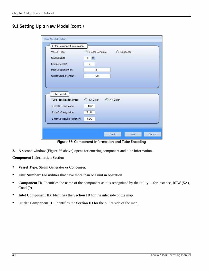
Figure 36: Component Information and Tube Encoding
2. A second window (Figure 36 above) opens for entering component and tube information.
Component Information Section
• Vessel Type: Steam Generator or Condenser.
• Unit Number: For utilities that have more than one unit in operation.
• Component ID: Identifies the name of the component as it is recognized by the utility —for instance, RFW (5A), Cond (9)
• Inlet Component ID: Identifies the Section ID for the inlet side of the map.
• Outlet Component ID: Identifies the Section ID for the outlet side of the map.
40 Apollo™ TSB Operating Manual

Chapter 9. Map Building Tutorial
9.1 Setting Up a New Model (cont.)
Tube Encode Section
• Tube Identification Order:
• YX- determines the access on how the tubes will be identified on the map.
• XY- performs the same function but uses the XY access instead.
Enter X-Designation: Allows the user to identify what information will be displayed on the X access
Enter Y Designation: Allows the user to identify what information will be displayed on the Y access.
Enter Section Designation: Allows the user the ability to identify how Sections will be named.
When you have entered this information, click Next.
Figure 37: Tube Materials Screen
3. The Tube Materials window (Figure 37 above) opens. Click on Add to enter tube type and size. Once you have identified all materials, click Finish.
Apollo™ TSB Operating Manual 41

Chapter 9. Map Building Tutorial
9.1 Setting Up a New Model (cont.)
Figure 38: Section Creation Window
4. The Section Setup window will appear. Enter the following information to organize your sections:
• Section Label: Allows users to identify the section with which they intend to start. Condensers may have numerous sections, so this option is particularly useful.
• Section Description: User entered information pertaining to the section.
• Step Type (Tube Pitch): Allows the user to select the tubing pitch that most closely matches that of the component being modeled.
• Pitch: Allows the user to select the X and Y pitch of the tube sheet map.
• Number of Tubes: Here the user selects the number of tubes to be entered onto the initial map. The user should always select more tubes than actually needed so that there are extra tube symbols available—remember, it is easier to remove a tube symbol than to add it later.
42 Apollo™ TSB Operating Manual

Chapter 9. Map Building Tutorial
9.1 Setting Up a New Model (cont.)
• Tube Encode Display Option: Allows the user to choose how the map information will be displayed.
• Internal Settings— None, ROW, TUB, allows the user to show NO information inside the tube symbol, Row information inside the tube symbol, or Tube (TUB) information inside the tube symbol. Typically TUB information will be displayed.
• External Settings—None, ROW, TUB, allows the user to perform the same function as above, with the exception that the selected information will be identified on the outside of the created map. This area usually shows ROW information.
9.1.1 Section Number and Sequencing
The Section Number and Sequencing tab allows the user to identify how the tube numbering sequence will be identified.
Figure 39: Section Numbering and Sequencing
Sequencing —This information ties back to where the user selected YX or XY on the NEW MODEL SETUP screen.
• The ROW SEQUENCING options are TOP to BOTTOM, or BOTTOM to TOP
• The TUB SEQUENCING options are LEFT to RIGHT, or RIGHT to LEFT.
Apollo™ TSB Operating Manual 43

Chapter 9. Map Building Tutorial
9.1.1 Section Number and Sequencing (cont.)
Numbering Options permits the following options: NUMERIC, ALPHA, ALPHA NUMBERIC, or NUMERIC ALPHA.
Is There A ROW 1 in every TUB? Unlike Steam Generator inspections which tend to use true triangular pitch numbering (combining even rows with odd columns), in BOP, numbering is often done with the use of sequential numbering that always starts with a tube 1 in every row. Select this option if all rows will start with tube one (1).
Click OK to create your new map.
Figure 40: New User Created Map
Once the new map appears on the screen, the user will notice that the map is shaded and the Move button is highlighted.
Note: GE suggests that the user move the map (left click and hold with the cursor, then drag the map) to create white background space on all sides of the map; this will allow for easier editing later.
Once the map has been repositioned, right click on any of the white space bordering the map to set the tubes in place.
Move Button
44 Apollo™ TSB Operating Manual

Chapter 9. Map Building Tutorial
9.1.2 Map Editing
Several functions in the Edit section assist in creating the final shape of the map.
Figure 41: Map for Editing
Zoom Features: Allow the user to magnify or reduce the magnification of the displayed map.
Undo/Redo Feature: Allows the user to back out of a function (or several functions) that may not have been correct. The Redo button allows you to reapply an undone function.
One: Provides the user with the ability to select a single tube.
Rectangle: Allows the user to select several tubes simultaneously by holding the left mouse button down and dragging a box around the tubes to be selected.
Line: Allows the user to draw a line through the tubes to be selected again using the left mouse button.
All This selection permits the user to select all of the tubes in the bundle, the function is activated when the user selects any tube in the section with the left mouse button.
Cut: Allows the user to cut an entire section, or part of one from the existing map.
Copy: The copy feature allows the user to copy sections of the map as a way to lessen map creation time. If there are identical or similar sections on the map, the user can select copy to recreate new section.
Apollo™ TSB Operating Manual 45

Chapter 9. Map Building Tutorial
9.1.2 Map Editing (cont.)
Paste: Used with the Cut or Copy function; once Cut or Copy has been used, the user can select Paste, and then by clicking on the section of the map where the new tubes should be placed, the area will be pasted. Figure 42 below is an example of the Copy and Paste function.
Figure 42: Copy and Paste Function
Notice that, for both sections, Row 1 Tube 1 is in the upper left hand corner of the map.
46 Apollo™ TSB Operating Manual

Chapter 9. Map Building Tutorial
9.1.2 Map Editing (cont.)
Flip tools allow the user to change the orientation of the map for a single section or all tubes. For example, if the section on the right hand side of the screen was a second quadrant of tubes to be inspected, a user can perform the following steps:
1. Select the Model tab on the software toolbar.
2. Select the New Section button
3. Enter the new section ID.
4. Be sure to fill in the Tube Encode display options.
5. Click OK.
6. A series of additional tubes will appear on the map; for this example, click the Delete button to remove them from the screen.
7. A message will appear saying, “There are no more tubes in the section you created, and would you like to remove this section?”. Select “No”.
8. Return to the Edit tab on the screen.
9. Using the Rectangle selection tool, select all the tubes in the section on the right hand side of the screen.
10. Right click on one of the tubes in the selected section; a window will appear with the properties of the tube selected.
11. In the Section window of this screen, use the drop-down box to change the section information to the new section ID that has been created.
12. Right-click on a white section of the map background, and all the tubes selected will be updated to reflect the new section ID. See Figure 43 on the next page for an example.
Apollo™ TSB Operating Manual 47

Chapter 9. Map Building Tutorial
9.1.2 Map Editing (cont.)
Figure 43: Edited Map with Updated Tubes
In Figure 43 above, the Section ID has been changed to 62 from 61, and the tube numbering for the new section is now right to left, top to bottom, by using the Flip Horizontal feature.
48 Apollo™ TSB Operating Manual

Chapter 9. Map Building Tutorial
9.1.2 Map Editing (cont.)
Figure 44 below is an example of a typical feedwater heater map displaying the inlet and outlet sides together, built using the functions explained in this tutorial.
Figure 44: Feedwater Heater Model
Apollo™ TSB Operating Manual 49

Chapter 9. Map Building Tutorial
[no content intended for this page - proceed to next page]
50 Apollo™ TSB Operating Manual


www.ge-mcs.com
©2012 General Electric Company. All rights reserved.Technical content subject to change without notice.
021-002-597 Rev. 2
Customer Support Centers
North/South America50 Industrial Park RoadLewistown, PA 17044U.S.A.Tel: 866 243 2638 (toll-free)
717 242 0327
GermanyRobert Bosch Str. 350354 HürthGermanyTel: +49 2233 601 0
United Kingdom/Ireland892 Charter Avenue CanleyCoventry CV4 8AFEnglandTel: +44 845 130 3925
France68, Chemin des OrmeauxLimonest 69760FranceTel: +33 47 217 9216
SpainSan Maximo,31, Planta 4A, Nave 6Madrid 28041SpainTel: +34 195 005 990
China5F, Building 1, No. 1 Huatuo Road,Zhangiang High-Tech ParkShanghai 201203ChinaTel: +86 800 915 9966 (toll-free)
+86 (0)21-3877 7888
Floor 5, Linkchart Center2 Tai Yip StreetKwun Tong, KowloonHong KongTel: +852 3761 1761Fax: +852 2877 0868
Japan7F Medie Corp Bldg. 82-4-14-Kichijoji Honcho,Musashino-shiTokyo 180-0004JapanTel: +81 442 67 7067
AustraliaLevel 2, Building 2, 572 Swan Street.Burnley, VIC, 3121 AustraliaTel: +61 0400 224 329
E-mail: [email protected]


