558
NATO UNCLASSIFIED APP-6(C) NATO JOINT MILITARY SYMBOLOGY APP-6(C) ORIGINAL NATO UNCLASSIFIED
NATO UNCLASSIFIED APP-6(C)
NATO JOINT MILITARY SYMBOLOGY
APP-6(C)
ORIGINAL NATO UNCLASSIFIED

NATO UNCLASSIFIED APP-6(C)
ORIGINAL NATO UNCLASSIFIED
(INTENTIONALLY BLANK)
NATO UNCLASSIFIED APP-6(C)
i ORIGINAL
NATO UNCLASSIFIED
APP-6(C)
NATO JOINT MILITARY SYMBOLOGY
MAY 2011

NATO UNCLASSIFIED APP-6(C)
ii ORIGINAL
NATO UNCLASSIFIED
(INTENTIONALLY BLANK)

NATO lJNCLASSIFIED APP-6(C)
NORTH ATLANTIC TREATY ORGANISATION
NATO STANDARDIZATION AGENCY (NSA)
NATO LETTER OF PROMULGATION
24 May 2011
1. APP-6(C) - NATO JOINT MILITARY SYMBOLOGY is a NATO UNCLASSIFIED publication. The agreement of NATO nations to use this publication is recorded in STANAG 2019.
2. APP-6(C) is effective on receipt. It supercedes APP-6(B), which shall be destroyed in accordance with the local procedure for the destruction of documents.
Cihangir AKSIT, TUR Civ Director, NATO Standardization Agency
iii ORIGINAL
NATO UNCLASSIFIED

NATO UNCLASSIFIED APP-6(C)
iv ORIGINAL
NATO UNCLASSIFIED
(INTENTIONALLY BLANK)
NATO UNCLASSIFIED APP-6(C)
v ORIGINAL
NATO UNCLASSIFIED
NATIONAL LETTER OF PROMULGATION
NATO UNCLASSIFIED APP-6(C)
vi ORIGINAL
NATO UNCLASSIFIED
(INTENTIONALLY BLANK)

NATO UNCLASSIFIED APP-6(C)
vii ORIGINAL
NATO UNCLASSIFIED
RECORD OF CHANGES Change Date
Date Entered
Effective Date
By Whom Entered

NATO UNCLASSIFIED APP-6(C)
viii ORIGINAL
NATO UNCLASSIFIED
(INTENTIONALLY BLANK)

NATO UNCLASSIFIED APP-6(C)
ix ORIGINAL
NATO UNCLASSIFIED
RECORD OF RESERVATIONS BY NATIONS
CHAPTER RECORD OF RESERVATIONS BY NATIONS
General DEU, GRC, USA
NATO UNCLASSIFIED APP-6(C)
x ORIGINAL
NATO UNCLASSIFIED
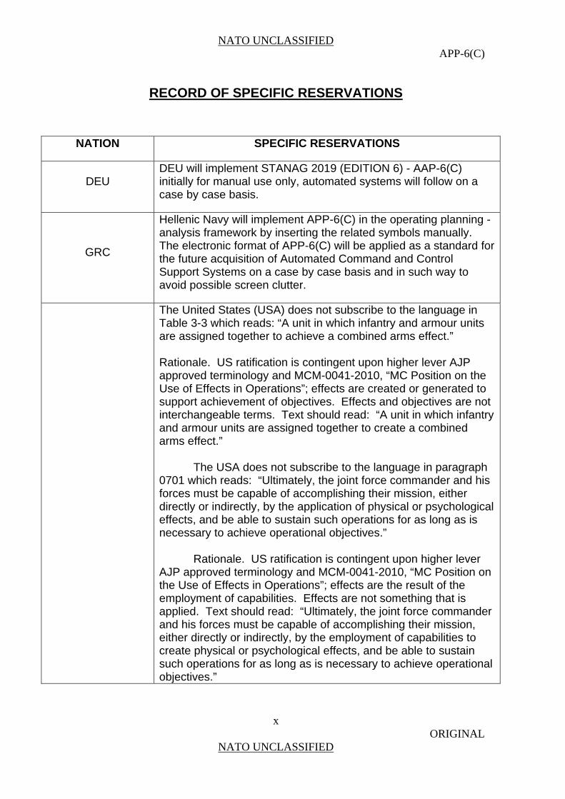
RECORD OF SPECIFIC RESERVATIONS
NATION SPECIFIC RESERVATIONS
DEU DEU will implement STANAG 2019 (EDITION 6) - AAP-6(C) initially for manual use only, automated systems will follow on a case by case basis.
GRC
Hellenic Navy will implement APP-6(C) in the operating planning - analysis framework by inserting the related symbols manually. The electronic format of APP-6(C) will be applied as a standard for the future acquisition of Automated Command and Control Support Systems on a case by case basis and in such way to avoid possible screen clutter.
The United States (USA) does not subscribe to the language in Table 3-3 which reads: “A unit in which infantry and armour units are assigned together to achieve a combined arms effect.” Rationale. US ratification is contingent upon higher lever AJP approved terminology and MCM-0041-2010, “MC Position on the Use of Effects in Operations”; effects are created or generated to support achievement of objectives. Effects and objectives are not interchangeable terms. Text should read: “A unit in which infantry and armour units are assigned together to create a combined arms effect.” The USA does not subscribe to the language in paragraph 0701 which reads: “Ultimately, the joint force commander and his forces must be capable of accomplishing their mission, either directly or indirectly, by the application of physical or psychological effects, and be able to sustain such operations for as long as is necessary to achieve operational objectives.” Rationale. US ratification is contingent upon higher lever AJP approved terminology and MCM-0041-2010, “MC Position on the Use of Effects in Operations”; effects are the result of the employment of capabilities. Effects are not something that is applied. Text should read: “Ultimately, the joint force commander and his forces must be capable of accomplishing their mission, either directly or indirectly, by the employment of capabilities to create physical or psychological effects, and be able to sustain such operations for as long as is necessary to achieve operational objectives.”
NATO UNCLASSIFIED APP-6(C)
xi ORIGINAL
NATO UNCLASSIFIED
PREFACE
0001. This standard provides common operational symbology along with details on its display and plotting to ensure the compatibility and, to the greatest extent possible, the interoperability of North Atlantic Treaty Organization (NATO) command and control systems, operations, and training and is intended to be equally applicable to operations conducted by a coalition of NATO, partners, non-NATO nations or other organisations.
0002. This new edition reflects a baseline of agreed changes, provides additional symbols, and reflects the harmonization initialised with all services.
0003. Allied Procedural Publication (APP)-6(C) focuses on the building block nature of military symbols. It contains figures and tables that provide the user with standard frames, icons, modifiers, and amplifiers using colour, graphic and alphanumeric representations along with guidelines for their use. Each of the symbols shown is a reflection of NATO doctrine.
0004. APP-6(C) is designed to be flexible enough to accommodate further change, development and input from the operators and users. Changes to these symbols and the addition of new symbol sets will be worked through NATO procedures.

NATO UNCLASSIFIED APP-6(C)
xii ORIGINAL
NATO UNCLASSIFIED
(INTENTIONALLY BLANK)
NATO UNCLASSIFIED APP-6(C)
xiii ORIGINAL
NATO UNCLASSIFIED
NATO JOINT MILIARY SYMBOLOGY
CONTENTS
Chapter 1 Military Symbols 1-1
Introduction 1-1
Detailed Requirements 1-4
Technical Specifications 1-12
Chapter 2 Air Symbols 2-1
Building Air Symbols 2-2
Icons 2-6
Modifiers 2-14
Missiles 2-24
Chapter 3 Land Symbols 3-1
Introduction 3-1
Land Unit, Individual, and Organization Symbols 3-2
Land Equipment Symbols 3-60
Land Installation Symbols 3-81
Chapter 4 Maritime Symbols 4-1
Surface Symbols 4-2
Subsurface Symbols 4-30
Chapter 5 Space Symbols 5-1
Building Space Symbols 5-2
Icons 5-6
Modifiers 5-11
Chapter 6 Stability Activities and Civil Support Activities Symbols 6-1
Chapter 7 Control Measure Symbols 7-1
Command and Control 7-5
Manoeuvre 7-25
Airspace 7-71
Maritime 7-91
Deception 7-131
Fires 7-133
NATO UNCLASSIFIED APP-6(C)
xiv ORIGINAL
NATO UNCLASSIFIED
Force Protection 7-158
Sustainment 7-208
Intelligence 7-233
Abbreviations and Acronyms 7-234
Appendix A: Mission Tasks and Mission Task Verbs 7-A-1
Chapter 8 Meteorological Symbols 8-1
Introduction 8-1
Weather Symbols 8-2
Annex A Symbol Identification Codes A-1
Annex B Comparative Formations/Unit Designations B-1
Lexicon L-1
Acronyms and Abbreviations L-1
Terms and Definitions L-5
Reference Publications R-1
NATO UNCLASSIFIED APP-6(C)
1-1 ORIGINAL
NATO UNCLASSIFIED
CHAPTER 1
MILITARY SYMBOLS
SECTION I - INTRODUCTION
Scope
0101. This publication provides a standardized, structured set of graphical symbols for the display of information in military systems and applications. A standard method for symbol construction is provided using common building blocks which shall be used to create current symbol sets as well as for creating sets that may be needed in future1.
Purpose
0102. In command and control of military operations, the reality of the displayed operational picture, its correct assessment and the decision-making speed are decisive factors. In joint military operations, it is imperative to have a common language clearly understood among all users. Graphical representation of objects, commands, movements and additional information (including alphanumeric text and colours) are observed and readily understood faster than merely text alone. This is valid even more for a user population with a widely different background of language, component, knowledge and experience. A common standard of joint military symbols is therefore an important element to enhance efficiency and contribute to success in joint operations.
0103. The purpose of this publication is to establish a common standard for the design, development and use of symbols depicting joint military activities. The publication aims to provide a standard visual portrayal for all command and control (C2) symbols and control measure symbols.
Applicability
0104. Allied Procedural Publication (APP)-6(C) applies to electronic/automated and hand-drawn graphic displays, both multi-coloured and monochrome. It shall be applied to mapping/charting as well as to engineering and design of system symbols.
0105. APP-6(C) shall be used by all North Atlantic Treaty Organization (NATO) forces involved in operations, for system development, and training. It aims to serve as the basic standard building set for future NATO implementations of symbol sets used in manual applications and electronic display systems. Any nation that wishes to work with NATO is invited to use the same standard.
NATO UNCLASSIFIED APP-6(C)
1-2 ORIGINAL
NATO UNCLASSIFIED
Content
0106. This publication provides building blocks for the standard composition of symbols. This includes frame, icon, amplifier and modifier using colour, graphic and alphanumeric representations. It gives detailed standards and requirements for symbol construction and composition with a certain degree of flexibility for special user’s needs.
0107. The symbol set encompasses the graphic representation of units, equipment, installations, and other elements and activities relevant to joint military operations. It contains the building blocks for joint military symbols from the domains air (chapter 2), land (chapter 3), sea/maritime (chapter 4), space (chapter 5) and the display of stability activities and civil support activities (chapter 6).
0108. In addition APP-6(C) contains listed standardized symbols and figures for control measures (chapter 7) and an International Standardization Organization (ISO) meteorological symbol set (chapter 8).
Dimensions of Joint Military Symbology
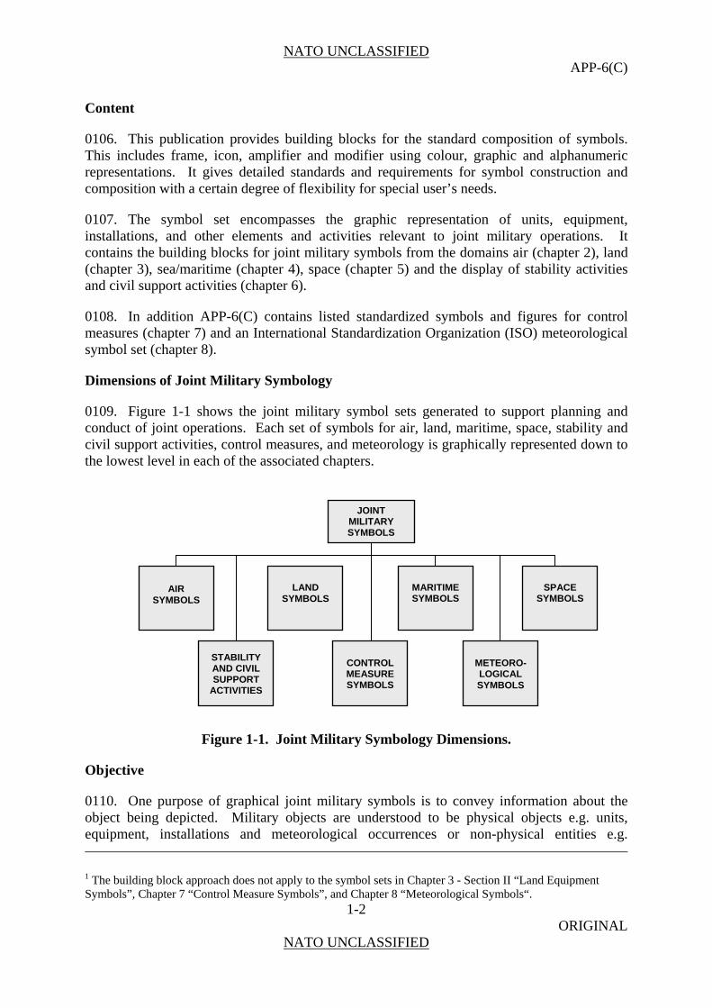
0109. Figure 1-1 shows the joint military symbol sets generated to support planning and conduct of joint operations. Each set of symbols for air, land, maritime, space, stability and civil support activities, control measures, and meteorology is graphically represented down to the lowest level in each of the associated chapters.
Figure 1-1. Joint Military Symbology Dimensions.
Objective
0110. One purpose of graphical joint military symbols is to convey information about the object being depicted. Military objects are understood to be physical objects e.g. units, equipment, installations and meteorological occurrences or non-physical entities e.g.
1 The building block approach does not apply to the symbol sets in Chapter 3 - Section II “Land Equipment Symbols”, Chapter 7 “Control Measure Symbols”, and Chapter 8 “Meteorological Symbols“.
JOINT MILITARY SYMBOLS
MARITIME SYMBOLS
LAND
SYMBOLS
AIR
SYMBOLS
CONTROL MEASURESYMBOLS
METEORO- LOGICAL SYMBOLS
STABILITY AND CIVIL SUPPORT
ACTIVITIES
SPACE
SYMBOLS

NATO UNCLASSIFIED APP-6(C)
1-3 ORIGINAL
NATO UNCLASSIFIED
planning, control measures, or anticipated locations with temporarily assigned characteristics or temporary validity. Additionally, symbols are also used to convey activities and operations for stability and civil support activities.
0111. While the focus of this publication is the display of symbols in modern multi-chromatic electronic systems, all symbols must be usable in monochromatic systems and as hand-drawn symbols. The need to reduce information cluttering a screen underlines the requirement of symbol display options with the possibility of reducing size and displayed information of symbols.
0112. The engineering and design of symbols and the composition of their building blocks must take into account considerations of human factors, such as symbol recognition and legibility across a variety of illumination conditions, map backgrounds, symbol size, display types, and under mental and physical fatigue.
NATO UNCLASSIFIED APP-6(C)
1-4 ORIGINAL
NATO UNCLASSIFIED
SECTION II - DETAILED REQUIREMENTS
0113. Icon-based symbols represent units, equipment, installations, and activities from all dimensions, and meteorological occurrences. An icon-based symbol is a composition of a frame, fill, icon, modifiers, and amplifiers. These elements are located within and around a virtual octagon. The placement of the various elements is explained in the following paragraphs.
0114. The components of an icon-based symbol provide information about the standard identity, battle dimension, status, and mission of an operational object.
a. Frame. The frame is the border of a symbol. It does not include associated information inside or outside of the border. The frame serves as the base to which other symbol components are added. Though sometimes optional, in most cases a frame surrounds an icon. When a frame is included in a symbol, its shape shall indicate the standard identity, dimension, and status of the object being represented. Table 1-1 provides the frame shapes. A frame can be black or white depending on display background, or it can be coloured, using the default colours in Table 1-4, to provide enhanced presentation information about standard identity.
(1) Standard identity. In imagery interpretation, identity is the discrimination between objects within a particular type or class (AAP-6). Standard identity reflects the relationship between the viewer and the operational object being monitored. The standard identity categories are unknown, assumed friend, friend, neutral, suspect, and hostile. In the realm of surface operation symbols, a circle or rectangle frame is to denote friend or assumed friend standard identity, a diamond frame to denote hostile or suspect standard identity, a square frame to denote neutral standard identity, and a quatrefoil frame to denote unknown and pending standard identity. The symbols for air, space, and subsurface objects adhere to this logic, but with “open” frames (see Table 1-1).
(2) Dimension. A dimension defines the primary mission area for the object within the operational environment. An object can have a mission area above the earth's surface (i.e., in the air or outer space), on the earth's surface, or below the earth's surface. If the mission area of an object is on the earth's surface, it can be either on land or sea. The land dimension includes those mission areas on the land surface or close to the surface (e.g., land mines and underground shelters), whereas the sea surface dimension includes only those objects whose mission area is on the sea surface. The subsurface dimension includes those objects whose mission area is below the sea surface (e.g., submarines and sea mines). To clarify which dimension should be used for a given object, maritime surface units shall be depicted in the sea surface dimension. Aircraft, regardless of service ownership, shall be depicted in the air dimension while air facilities shall be depicted as land installations. Ground equipment shall be depicted in the land dimension. Likewise, a landing craft whose primary mission is ferrying personnel or equipment to and from shore are represented in the sea surface dimension. However, a landing craft whose primary mission is to fight on land is a ground asset and is represented in the land dimension.

NATO UNCLASSIFIED APP-6(C)
1-5 ORIGINAL
NATO UNCLASSIFIED
Table 1-1. Standard identities and dimensions.
Units / Entities
Standard Identity
Air Space Land Sea
Surface
Sea Sub-
surface
Equip-ment
Instal-lations Activity
Pending2
Unknown
Suspect
Hostile
Neutral
Assumed Friend
Friend
As shown in Table 1-1., a closed frame shall be used to denote the land and sea surface dimension, a frame open at the bottom to denote the air/space dimension, and a frame open at the top to denote the subsurface dimension. A solid line is used to denote the certainty of identification of standard identity and shall identify the symbol as friend, hostile, neutral and unknown.
2 The term “pending” is not recognized as a standard identity within STANAG 1241; it is depicted as a status.
NATO UNCLASSIFIED APP-6(C)
1-6 ORIGINAL
NATO UNCLASSIFIED
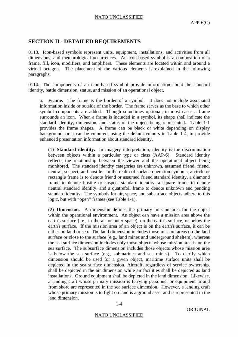
A black and white dotted line (one dot black and one dot white in an alternating pattern) denotes the uncertainty of identification of standard identity and shall identify the symbol as assumed friend, suspect, or pending. Figure 1-2 shows the display of black and white dotted lines on various backgrounds.
Figure 1-2. Examples of Black and White Dotted Lines on Various Backgrounds.
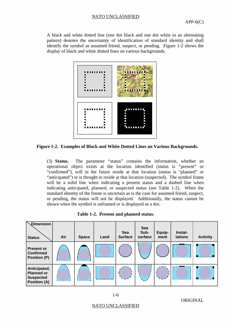
(3) Status. The parameter “status” contains the information, whether an operational object exists at the location identified (status is “present” or “confirmed”), will in the future reside at that location (status is "planned” or “anticipated") or is thought to reside at that location (suspected). The symbol frame will be a solid line when indicating a present status and a dashed line when indicating anticipated, planned, or suspected status (see Table 1-2). When the standard identity of the frame is uncertain as is the case for assumed friend, suspect, or pending, the status will not be displayed. Additionally, the status cannot be shown when the symbol is unframed or is displayed as a dot.
Table 1-2. Present and planned status.
Dimension
Status Air Space Land
Sea Surface
Sea Sub-
surface Equip-ment
Instal-lations Activity
Present or Confirmed Position (P)
Anticipated, Planned or Suspected Position (A)

NATO UNCLASSIFIED APP-6(C)
1-7 ORIGINAL
NATO UNCLASSIFIED
b. Colour/Fill. The fill is the interior area within a symbol. In framed symbols, colour shall provide a redundant clue with regard to standard identity. If colour is not used, the fill is transparent. In unframed symbols, colour shall be the sole indicator of standard identity, excluding text amplifiers. Table 1-4 defines the default colours that shall be used to designate standard identity when coloured symbols are either hand drawn or displayed electronically.
c. Icon. The icon is the innermost part of a symbol which provides an abstract pictorial or alphanumeric representation of units, equipment, installations, activities, or operations. This publication distinguishes between icons that must be framed or unframed and icons where framing is optional.
d. Modifiers. A modifier provides an abstract pictorial or alphanumeric representation that is displayed in conjunction with an icon. The modifier provides additional information about the icon (i.e., unit, equipment, installation, or activity) being displayed. Modifiers conform to the bounding octagon and are placed either above or below the icon. This publication defines various types of modifiers and indicates where each is to be placed in relation to the icon within the symbol.
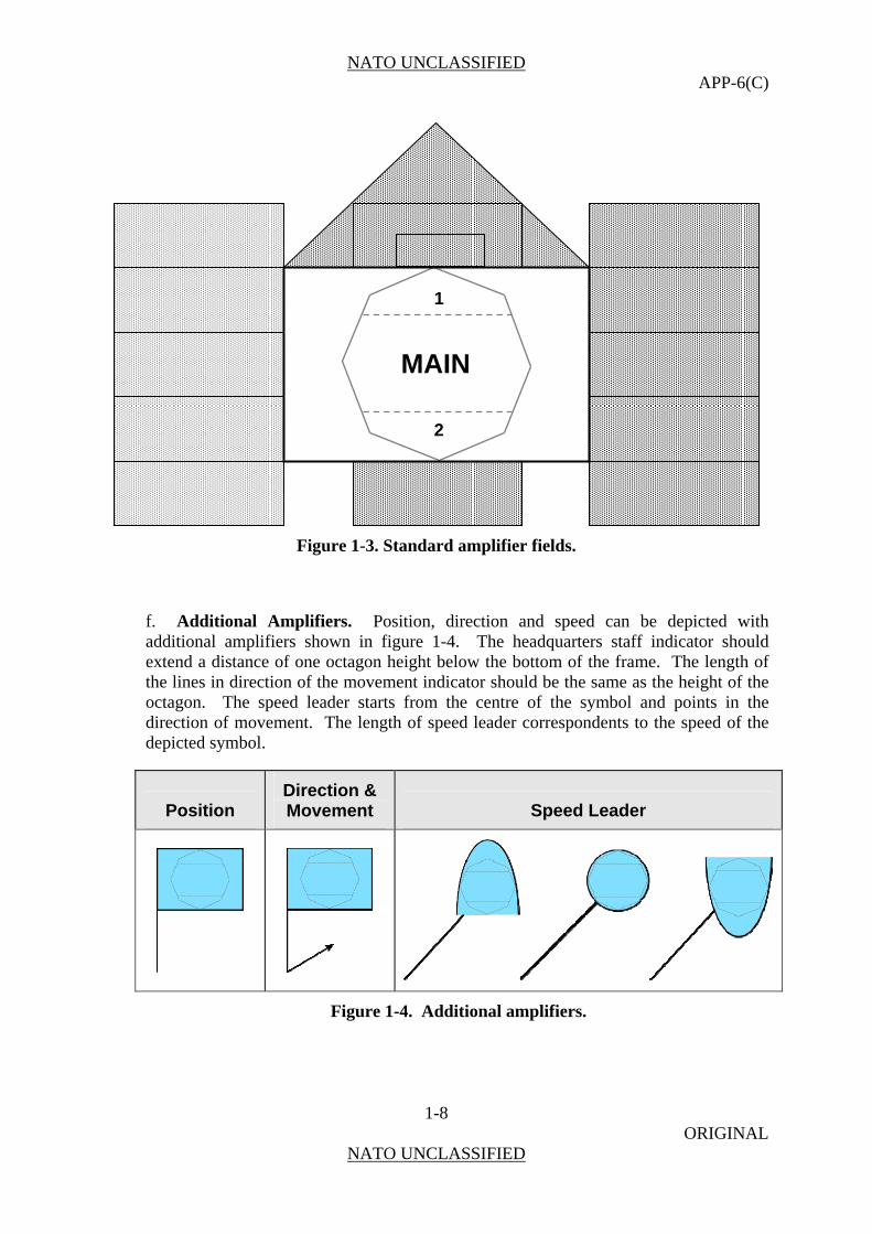
e. Amplifiers. An amplifier provides additional information about the symbol being portrayed and is displayed outside the frame. The available amplifier fields are presented around the friendly land unit symbol frame in Figure 1-3. The amplifier field descriptions will vary with domain and will be detailed within the respective chapters. The default placement of amplifiers in fields around symbols is shown in each of the dimension chapters, in Chapter 6 for stability and civil support activities, and in Chapter 7 for control measure symbols. Not all amplifiers are applicable to all symbols. However, when any amplifier is displayed, it shall be defined in accordance with the appropriate standard identity or control measure symbol. It is recommended that for the purposes of de-cluttering the display only essential amplifiers are used.
NATO UNCLASSIFIED APP-6(C)
1-8 ORIGINAL
NATO UNCLASSIFIED
Figure 1-3. Standard amplifier fields.
f. Additional Amplifiers. Position, direction and speed can be depicted with additional amplifiers shown in figure 1-4. The headquarters staff indicator should extend a distance of one octagon height below the bottom of the frame. The length of the lines in direction of the movement indicator should be the same as the height of the octagon. The speed leader starts from the centre of the symbol and points in the direction of movement. The length of speed leader correspondents to the speed of the depicted symbol.
Position Direction & Movement Speed Leader
Figure 1-4. Additional amplifiers.
MAIN
2
1
NATO UNCLASSIFIED APP-6(C)
1-9 ORIGINAL
NATO UNCLASSIFIED
Location of Icons and Modifiers inside the Octagon for Unit Symbols
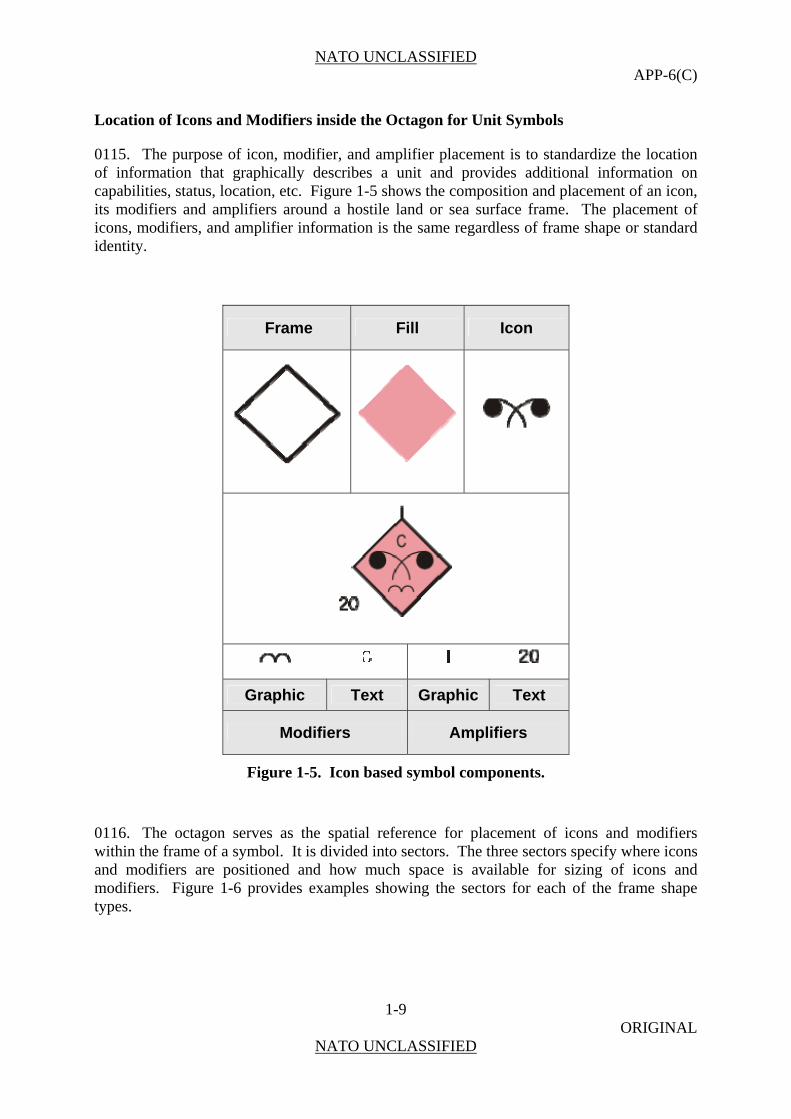
0115. The purpose of icon, modifier, and amplifier placement is to standardize the location of information that graphically describes a unit and provides additional information on capabilities, status, location, etc. Figure 1-5 shows the composition and placement of an icon, its modifiers and amplifiers around a hostile land or sea surface frame. The placement of icons, modifiers, and amplifier information is the same regardless of frame shape or standard identity.
Frame Fill Icon
Graphic Text Graphic Text
Modifiers Amplifiers
Figure 1-5. Icon based symbol components.
0116. The octagon serves as the spatial reference for placement of icons and modifiers within the frame of a symbol. It is divided into sectors. The three sectors specify where icons and modifiers are positioned and how much space is available for sizing of icons and modifiers. Figure 1-6 provides examples showing the sectors for each of the frame shape types.

NATO UNCLASSIFIED APP-6(C)
1-10 ORIGINAL
NATO UNCLASSIFIED
FRIENDLY HOSTILE
NEUTRAL UNKNOWN
Figure 1-6. Location of Icons and Modifiers.
0117. In general, icons should not be so large as to exceed the dimensions of the main sector of the octagon or touch the interior border of the frame. However, there are exceptions to this size rule. In those cases the icons will occupy the entire frame and must, therefore, exceed the dimensions of the main sector of the octagon and touch the interior border of the frame. These are called full frame icons (examples see Figure 1-7). Full frame icons occur only in the land domain (see Chapter 3).
Friendly Hostile Neutral
Unknown
Medical Medical Medical Medical
Figure 1-7. Examples for Full Frame Icons.
NATO UNCLASSIFIED APP-6(C)
1-11 ORIGINAL
NATO UNCLASSIFIED
Control measure symbols
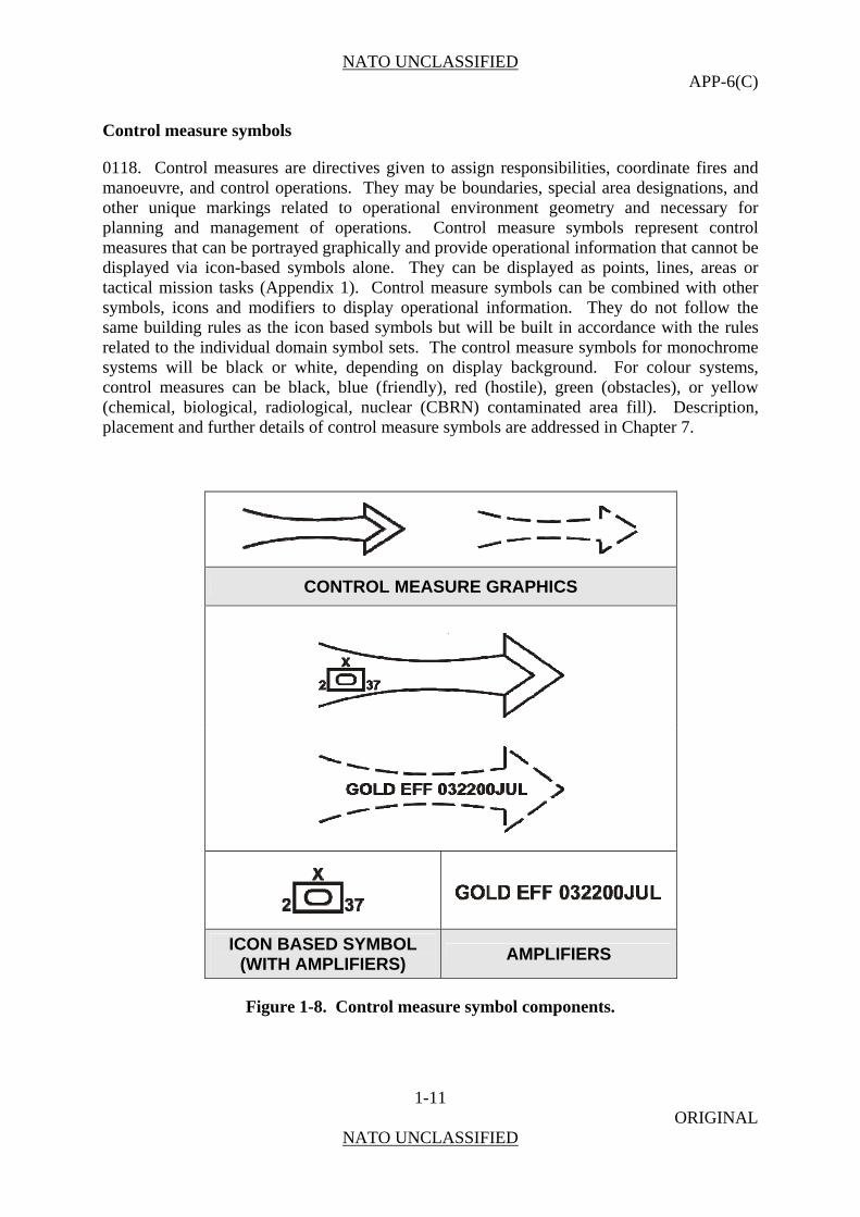
0118. Control measures are directives given to assign responsibilities, coordinate fires and manoeuvre, and control operations. They may be boundaries, special area designations, and other unique markings related to operational environment geometry and necessary for planning and management of operations. Control measure symbols represent control measures that can be portrayed graphically and provide operational information that cannot be displayed via icon-based symbols alone. They can be displayed as points, lines, areas or tactical mission tasks (Appendix 1). Control measure symbols can be combined with other symbols, icons and modifiers to display operational information. They do not follow the same building rules as the icon based symbols but will be built in accordance with the rules related to the individual domain symbol sets. The control measure symbols for monochrome systems will be black or white, depending on display background. For colour systems, control measures can be black, blue (friendly), red (hostile), green (obstacles), or yellow (chemical, biological, radiological, nuclear (CBRN) contaminated area fill). Description, placement and further details of control measure symbols are addressed in Chapter 7.
CONTROL MEASURE GRAPHICS
ICON BASED SYMBOL (WITH AMPLIFIERS)
AMPLIFIERS
Figure 1-8. Control measure symbol components.

NATO UNCLASSIFIED APP-6(C)
1-12 ORIGINAL
NATO UNCLASSIFIED
SECTION III - TECHNICAL SPECIFICATIONS
Scope
0119. This section provides additional technical specifications concerning the composition of symbols. These are intended to present guidance for an effective implementation of both icon based symbols and control measure symbols.
Technical Specification
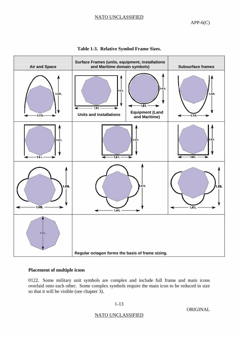
0120. The relative size of each symbol and symbol component shall be consistent within a given implementation. Each of these sizes can be related to length “L” as shown in Table 1-3.
0121. The frame seize shall be determined in relation to an octagon defining the outer boundary for all icons. “L” is the default length and height of the octagon. Frame length and height may vary from 1.0L to 1.5L, depending on the particular shape, as shown in Table 1-3. The minimum diameter of a dot should be 0.15L. In general, icons must not be so large as to touch the interior border of the frame. Only full frame icons are an exception to this sizing rule. They occupy the entire symbol and must therefore touch the interior border of the frame. The dimensions of unframed icons should be the same as framed icons.
Table 1-3. Relative Symbol Frame Sizes.
Air and Space
Surface Frames (units, equipment and
installations) Subsurface frames
NATO UNCLASSIFIED APP-6(C)
1-13 ORIGINAL
NATO UNCLASSIFIED
Table 1-3. Relative Symbol Frame Sizes.
Air and Space Surface Frames (units, equipment, installations
and Maritime domain symbols) Subsurface frames
Units and installations
Equipment (Land
and Maritime)
Regular octagon forms the basis of frame sizing.
Placement of multiple icons
0122. Some military unit symbols are complex and include full frame and main icons overlaid onto each other. Some complex symbols require the main icon to be reduced in size so that it will be visible (see chapter 3).
NATO UNCLASSIFIED APP-6(C)
1-14 ORIGINAL
NATO UNCLASSIFIED
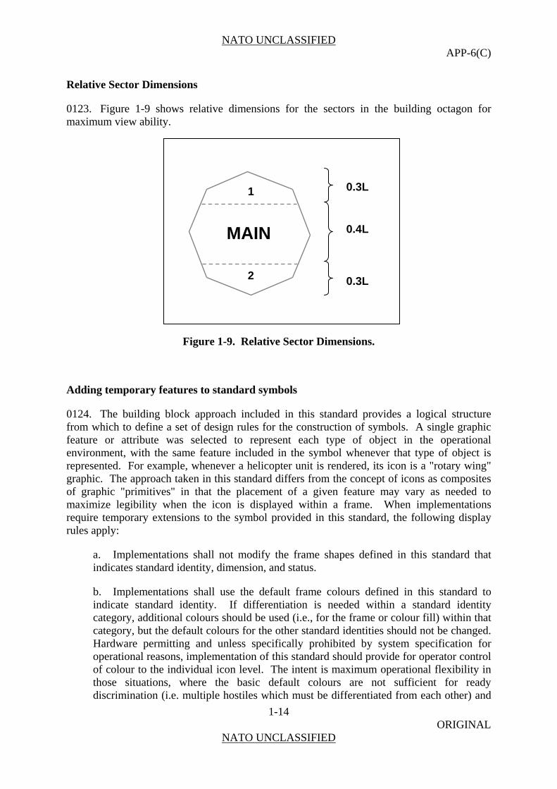
Relative Sector Dimensions
0123. Figure 1-9 shows relative dimensions for the sectors in the building octagon for maximum view ability.
Figure 1-9. Relative Sector Dimensions.
Adding temporary features to standard symbols
0124. The building block approach included in this standard provides a logical structure from which to define a set of design rules for the construction of symbols. A single graphic feature or attribute was selected to represent each type of object in the operational environment, with the same feature included in the symbol whenever that type of object is represented. For example, whenever a helicopter unit is rendered, its icon is a "rotary wing" graphic. The approach taken in this standard differs from the concept of icons as composites of graphic "primitives" in that the placement of a given feature may vary as needed to maximize legibility when the icon is displayed within a frame. When implementations require temporary extensions to the symbol provided in this standard, the following display rules apply:
a. Implementations shall not modify the frame shapes defined in this standard that indicates standard identity, dimension, and status.
b. Implementations shall use the default frame colours defined in this standard to indicate standard identity. If differentiation is needed within a standard identity category, additional colours should be used (i.e., for the frame or colour fill) within that category, but the default colours for the other standard identities should not be changed. Hardware permitting and unless specifically prohibited by system specification for operational reasons, implementation of this standard should provide for operator control of colour to the individual icon level. The intent is maximum operational flexibility in those situations, where the basic default colours are not sufficient for ready discrimination (i.e. multiple hostiles which must be differentiated from each other) and
MAIN
2
1 0.3L
0.3L
0.4L

NATO UNCLASSIFIED APP-6(C)
1-15 ORIGINAL
NATO UNCLASSIFIED
to assign a specific colour to a special interest target without reference to its standard identity. However, different shades or hues of a colour for different hostile formations, units, and threat rankings are not an option.
Line Width
0125. Because the symbol frame indicates both the standard identity and dimension of an object, it is critical that line width is sufficient to ensure frame legibility and discriminability at normal viewing distance. The optimum line width may differ depending on frame size and be affected by whether the frame is filled or unfilled and displayed in colour or black/white. Usability testing should be performed to identify the optimum rendering for a given implementation.
NATO UNCLASSIFIED APP-6(C)
1-16 ORIGINAL
NATO UNCLASSIFIED
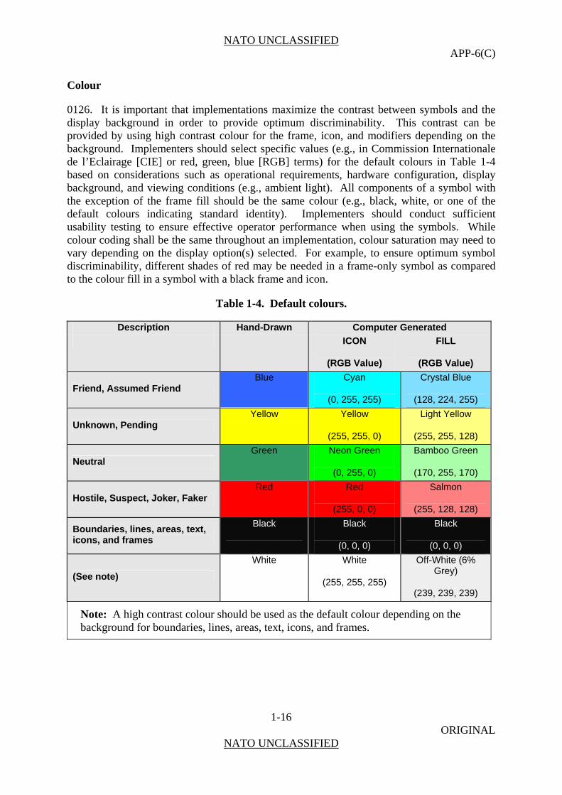
Colour
0126. It is important that implementations maximize the contrast between symbols and the display background in order to provide optimum discriminability. This contrast can be provided by using high contrast colour for the frame, icon, and modifiers depending on the background. Implementers should select specific values (e.g., in Commission Internationale de l’Eclairage [CIE] or red, green, blue [RGB] terms) for the default colours in Table 1-4 based on considerations such as operational requirements, hardware configuration, display background, and viewing conditions (e.g., ambient light). All components of a symbol with the exception of the frame fill should be the same colour (e.g., black, white, or one of the default colours indicating standard identity). Implementers should conduct sufficient usability testing to ensure effective operator performance when using the symbols. While colour coding shall be the same throughout an implementation, colour saturation may need to vary depending on the display option(s) selected. For example, to ensure optimum symbol discriminability, different shades of red may be needed in a frame-only symbol as compared to the colour fill in a symbol with a black frame and icon.
Table 1-4. Default colours.
Description Hand-Drawn Computer Generated
ICON
(RGB Value)
FILL
(RGB Value)
Friend, Assumed Friend Blue Cyan
(0, 255, 255)
Crystal Blue
(128, 224, 255)
Unknown, Pending Yellow Yellow
(255, 255, 0)
Light Yellow
(255, 255, 128)
Neutral Green Neon Green
(0, 255, 0)
Bamboo Green
(170, 255, 170)
Hostile, Suspect, Joker, Faker Red Red
(255, 0, 0)
Salmon
(255, 128, 128)
Boundaries, lines, areas, text, icons, and frames
Black
Black
(0, 0, 0)
Black
(0, 0, 0)
(See note)
White White
(255, 255, 255)
Off-White (6% Grey)
(239, 239, 239)
Note: A high contrast colour should be used as the default colour depending on the background for boundaries, lines, areas, text, icons, and frames.

NATO UNCLASSIFIED APP-6(C)
2-1 ORIGINAL
NATO UNCLASSIFIED
CHAPTER 2
AIR SYMBOLS
Scope
0201. This chapter covers symbols for air assets and their activities. Air installations and headquarters are covered in Chapter 3 “Land Symbols”, while airspace coordination and planning is part of Chapter 7 “Control Measures Symbols”.
Characteristics of Symbols for Air Operations
0202. Air assets use the third dimension in order to create effects that contribute to the achievement of joint force commander objectives. Reach, speed and manoeuvrability are some of their inherent capabilities.
0203. For this reason, in order to depict in near real time large areas with fast moving airspace users manoeuvring within all three dimensions, specific requirements for the air picture production have to be met:
a. The picture has to be updated near real time.
b. Vectors have to be provided in order to help to anticipate movement of own, neutral and hostile objects.
c. Wherever known, relevant data like “aircraft type,” “call sign,” “mission,” “origin,” “destination” etc. have to be affiliated to the objects without cluttering the display.
d. Objects may overlap on the display but must still be recognisable to controllers.
e. The display contains a multitude of non-military moving objects (civil aircraft); airspace control and de-confliction means; fire support coordination means; and installations (e.g. airfields).

NATO UNCLASSIFIED APP-6(C)
2-2 ORIGINAL
NATO UNCLASSIFIED
SECTION I – BUILDING AIR SYMBOLS
General
0204. This section establishes a single standard for developing air symbols. It includes a variety of air related icons, modifiers, and amplifiers for building symbols. However, no attempt to depict all possible air symbols has been made. Rather, a standard method for constructing these symbols is presented. Once the user is familiar with the prescribed system, any desired unit can be depicted using the logical sequence provided in this chapter. The symbols shown in this chapter are adequate for depicting all air standard identities defined in STANAG 1241. When representing not yet defined units, select the most appropriate symbol combination contained herein. Avoid using any symbols, or combinations and modifications of symbols that differ from those laid down in this publication. If, after searching icons and modifiers given in this publication, it is necessary to create a new symbol, explain the symbol in an accompanying legend.
Composition of Air Symbols
0205. An air symbol is composed of a frame, colour (fill), icon, modifiers, and amplifiers (not shown) (Figure 2-1). (See Table 2-1 for the steps used to build air symbols.)
Figure 2-1. Air Symbol Composition.
NATO UNCLASSIFIED APP-6(C)
2-3 ORIGINAL
NATO UNCLASSIFIED
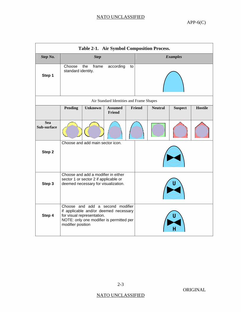
Table 2-1. Air Symbol Composition Process.
Step No. Step Examples
Step 1
Choose the frame according to standard identity.
Air Standard Identities and Frame Shapes
Pending Unknown Assumed Friend
Friend Neutral Suspect Hostile
Sea Sub-surface
Step 2
Choose and add main sector icon.
Step 3
Choose and add a modifier in either sector 1 or sector 2 if applicable or deemed necessary for visualization.
Step 4
Choose and add a second modifier if applicable and/or deemed necessary for visual representation. NOTE: only one modifier is permitted per modifier position
U
U
H

NATO UNCLASSIFIED APP-6(C)
2-4 ORIGINAL
NATO UNCLASSIFIED
Amplifier Fields
0206. On the tactical display, information about a displayed object is conveyed by the symbol via frame shape, icon/letter and colour coding. There may be, however, additional information that cannot be conveyed by graphical means, but by written (alphanumerical) information only.
0207. This information can be displayed either in secondary information fields outside the tactical screen, a method that forces the operator to a constant shift of focus and will not be considered further in this text, or by use of amplifier fields.
0208. The purpose of the amplifier fields described in this section is to standardize the display of additional alphanumerical information, i.e. on identity, location and movement, capabilities. Figure 2-2 shows the placement of amplifier fields around an air symbol frame. The placement of the label is the same regardless of frame shape or affiliation.
0209. In comparison to amplifier fields for land symbols, air amplifier fields –constitute a reduction in the amount of information displayed
0210. In the default mode, the label is not shown. It is the user’s task to define and call up for display the information considered to be necessary. Additionally, the user must be enabled to suppress the filled and displayed label to reduce screen clutter and call it up again as considered appropriate to the tactical situation. Table 2-2 provides a list of amplifier field content for air symbols and Table 2-3 provides a list of amplifier field content for weapons (missiles) in flight symbols.
Figure 2-2. Air Symbol Amplifier Fields.

NATO UNCLASSIFIED APP-6(C)
2-5 ORIGINAL
NATO UNCLASSIFIED
Table 2-2. Contents of Labels for Air Symbols (Example).
Field Field Title Description (Alternatives) Prefix (when applicable)
1 Track Number System Track Number TN
2 Call sign a) Airframe number
b) Mission call sign
3 Position and Movement, 3rd Dimension Info
Course [degrees]/Speed [knots] or Bearing [degrees]/Distance [nautical miles] Height [feet/flight level]
C/S B/D
4 Nation Nations Name: A 3-letter code indicating the
object’s country of origin (STANAG 1059)
5
Additional Information
For friendly units - Sensor or Weapon load, endurance, etc. For other Units - Credibility of Information
Table 2-3. Contents of Labels for Weapons in Flight (Example).
Field Field Title Description (Alternatives) Prefix (when applicable)
1 Track Number System Track Number TN
2 Name Weapon Type/Name
3 Position and Movement, 3rd Dimension Info
Course [degrees] /Speed [knots] or Bearing [degrees] / Distance [nautical miles] Height [feet/flight level]
C/S B/D
4 Nation Nations Name: A 3-letter code indicating the
object’s country of origin (STANAG 1059)
5 Additional Information
Threat Ranking
NATO UNCLASSIFIED APP-6(C)
2-6 ORIGINAL
NATO UNCLASSIFIED
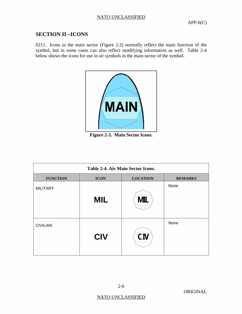
SECTION II –ICONS
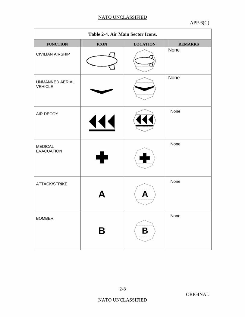
0211. Icons in the main sector (Figure 2.2) normally reflect the main function of the symbol, but in some cases can also reflect modifying information as well. Table 2-4 below shows the icons for use in air symbols in the main sector of the symbol.
Figure 2-3. Main Sector Icons.
Table 2-4. Air Main Sector Icons.
FUNCTION ICON LOCATION REMARKS
MILITARY
MIL
MIL
None
CIVILIAN
CIV
CIV
None

NATO UNCLASSIFIED APP-6(C)
2-7 ORIGINAL
NATO UNCLASSIFIED
Table 2-4. Air Main Sector Icons.
FUNCTION ICON LOCATION REMARKS
MILITARY FIXED WING
None
CIVILIAN FIXED WING
None
MILITARY ROTARY WING
None
CIVILIAN ROTARY WING
None
MILITARY BALLOON
None
CIVILIAN BALLOON
None
MILITARY AIRSHIP
None
NATO UNCLASSIFIED APP-6(C)
2-8 ORIGINAL
NATO UNCLASSIFIED
Table 2-4. Air Main Sector Icons.
FUNCTION ICON LOCATION REMARKS
CIVILIAN AIRSHIP
None
UNMANNED AERIAL VEHICLE
None
AIR DECOY
None
MEDICAL EVACUATION
None
ATTACK/STRIKE
A
A
None
BOMBER
B
B
None

NATO UNCLASSIFIED APP-6(C)
2-9 ORIGINAL
NATO UNCLASSIFIED
Table 2-4. Air Main Sector Icons.
FUNCTION ICON LOCATION REMARKS
CARGO
C
C
None
FIGHTER
F F
None
JAMMER / ELECTRONIC COUNTER-MEASURES J
J
None
TANKER
K
K
None
PATROL
P
P
None
RECONNAISSANCE
R
R
None

NATO UNCLASSIFIED APP-6(C)
2-10 ORIGINAL
NATO UNCLASSIFIED
Table 2-4. Air Main Sector Icons.
FUNCTION ICON LOCATION REMARKS
TRAINER
T
T
None
UTILITY
U
U
None
VSTOL
V
V
None
AIRBORNE COMMAND POST
ACP
ACP
None
AIRBORNE EARLY WARNING
AEW
AEW
None
ANTISURFACE WARFARE
ASUW
ASUW
None

NATO UNCLASSIFIED APP-6(C)
2-11 ORIGINAL
NATO UNCLASSIFIED
Table 2-4. Air Main Sector Icons.
FUNCTION ICON LOCATION REMARKS
ANTISUBMARINE WARFARE
ASW
ASW
None
COMMUNICATIONS
COM
COM
None
COMBAT SEARCH AND RESCUE
CSAR
CSAR
None
ELECTRONIC SUPPORT MEASURES ESM
ESM
None
GOVERNMENT
GOV
GOV
None
MINE COUNTERMEASURES
MCM
MCM
None

NATO UNCLASSIFIED APP-6(C)
2-12 ORIGINAL
NATO UNCLASSIFIED
Table 2-4. Air Main Sector Icons.
FUNCTION ICON LOCATION REMARKS
PERSONNEL RECOVERY
PR
PR
None
PASSENGER
PX
PX
None
SEARCH AND RESCUE
SAR
SAR
None
SUPRESSION OF ENEMY AIR DEFENCE
SEAD
SEAD
None
SPECIAL OPERATIONS FORCES SOF
SOF
None
ULTRA LIGHT
UL
UL
None
NATO UNCLASSIFIED APP-6(C)
2-13 ORIGINAL
NATO UNCLASSIFIED
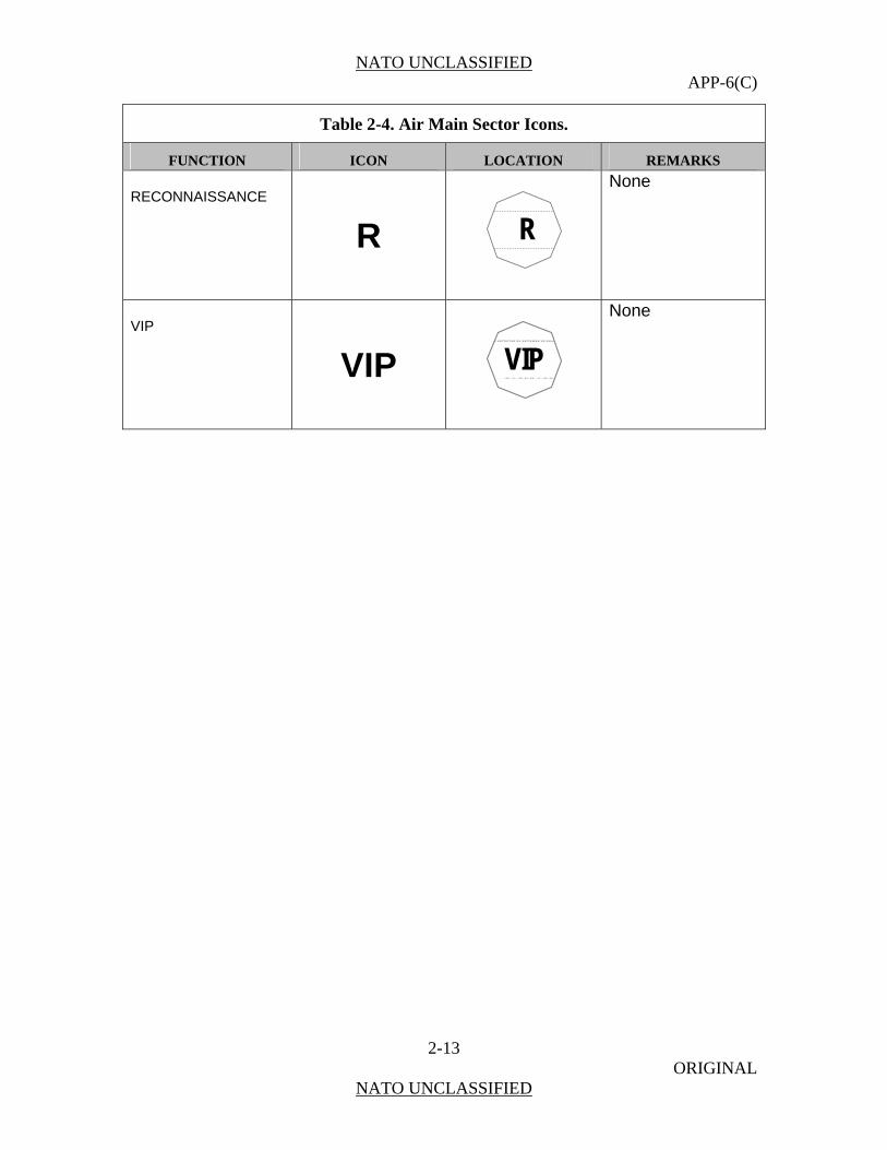
Table 2-4. Air Main Sector Icons.
FUNCTION ICON LOCATION REMARKS
RECONNAISSANCE
R
R
None
VIP
VIP VIP
None

NATO UNCLASSIFIED APP-6(C)
2-14 ORIGINAL
NATO UNCLASSIFIED
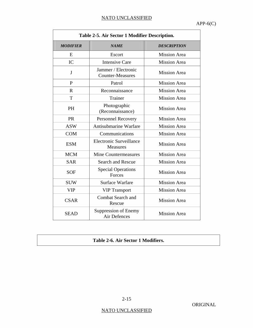
SECTION III – MODIFIERS
0212. Modifiers display additional information regarding the icon. Sector 1 modifiers are placed above the icon (Figure 2-4) and denote aircraft type or mission area (see Table 2-5). Table 2-6 shows sector 1 modifiers for air symbols.
Figure 2-4. Sector 1 Modifier Placement.
Table 2-5. Air Sector 1 Modifier Description.
MODIFIER NAME DESCRIPTION
A Attack Aircraft Type
B Bomber Aircraft Type
C Cargo Aircraft Type
F Fighter Aircraft Type
I Interceptor Mission Area
K Tanker Aircraft Type
U Utility Aircraft Type
V VSTOL Aircraft Type
PX Passenger Aircraft Type
UL Ultra-Light Aircraft Type
ACP Airborne Command Post Aircraft Type
ASUW Antisurface Warfare Mission Area
AEW Airborne Early Warning Aircraft Type
GOV Government Aircraft Type
MEDEVAC Mission Area
NATO UNCLASSIFIED APP-6(C)
2-15 ORIGINAL
NATO UNCLASSIFIED
Table 2-5. Air Sector 1 Modifier Description.
MODIFIER NAME DESCRIPTION
E Escort Mission Area
IC Intensive Care Mission Area
J Jammer / Electronic Counter-Measures
Mission Area
P Patrol Mission Area
R Reconnaissance Mission Area
T Trainer Mission Area
PH Photographic
(Reconnaissance) Mission Area
PR Personnel Recovery Mission Area
ASW Antisubmarine Warfare Mission Area
COM Communications Mission Area
ESM Electronic Surveillance
Measures Mission Area
MCM Mine Countermeasures Mission Area
SAR Search and Rescue Mission Area
SOF Special Operations
Forces Mission Area
SUW Surface Warfare Mission Area
VIP VIP Transport Mission Area
CSAR Combat Search and
Rescue Mission Area
SEAD Suppression of Enemy
Air Defences Mission Area
Table 2-6. Air Sector 1 Modifiers.

NATO UNCLASSIFIED APP-6(C)
2-16 ORIGINAL
NATO UNCLASSIFIED
DESCRIPTION ICON LOCATION REMARKS
MEDICAL EVACUATION
None
CARGO
C
C
Only in conjunction with air symbols.
ELECTRONIC COUNTER-MEASURES / JAMMER J
J
None
TANKER
K
K
Only in conjunction with air symbols.
PATROL
P
P
Only in conjunction with air symbols.
RECONNAISSANCE
R
R
Only in conjunction with air symbols.

NATO UNCLASSIFIED APP-6(C)
2-17 ORIGINAL
NATO UNCLASSIFIED
Table 2-6. Air Sector 1 Modifiers.
DESCRIPTION ICON LOCATION REMARKS
TRAINER
T
T
None
UTILITY
U
U
None
AIRBORNE COMMAND POST
ACP
ACP
None
AIRBORNE EARLY WARNING
AEW
AEW
None
ANTISURFACE WARFARE
ASUW
ASUW
None
ANTISUBMARINE WARFARE
ASW
ASW
None

NATO UNCLASSIFIED APP-6(C)
2-18 ORIGINAL
NATO UNCLASSIFIED
Table 2-6. Air Sector 1 Modifiers.
DESCRIPTION ICON LOCATION REMARKS
COMMUNICATIONS
COM
COM
None
COMBAT SEARCH AND RESCUE
CSAR
CSAR
None
ELECTRONIC SUPPORT MEASURES ESM
ESM
None
GOVERNMENT FLIGHT
GOV
GOV
None
MINE COUNTERMEASURES
MCM
MCM
None
PERSONNAL RECOVERY
PR
PR
None

NATO UNCLASSIFIED APP-6(C)
2-19 ORIGINAL
NATO UNCLASSIFIED
Table 2-6. Air Sector 1 Modifiers.
DESCRIPTION ICON LOCATION REMARKS
PASSENGER PLANE
PX
PX
None
SEARCH AND RESCUE
SAR
SAR
None
SUPRESSION OF ENEMY AIR DEFENCES SEAD
SEAD
None
SPECIAL OPERATIONS FORCES SOF
SOF
None
ULTRA LIGHT
UL
UL
None
PHOTOGRAPHIC
PH PH
None

NATO UNCLASSIFIED APP-6(C)
2-20 ORIGINAL
NATO UNCLASSIFIED
Table 2-6. Air Sector 1 Modifiers.
DESCRIPTION ICON LOCATION REMARKS
VIP
VIP VIP
None
ESCORT
E E
None
INTENSIVE CARE
IC IC
None
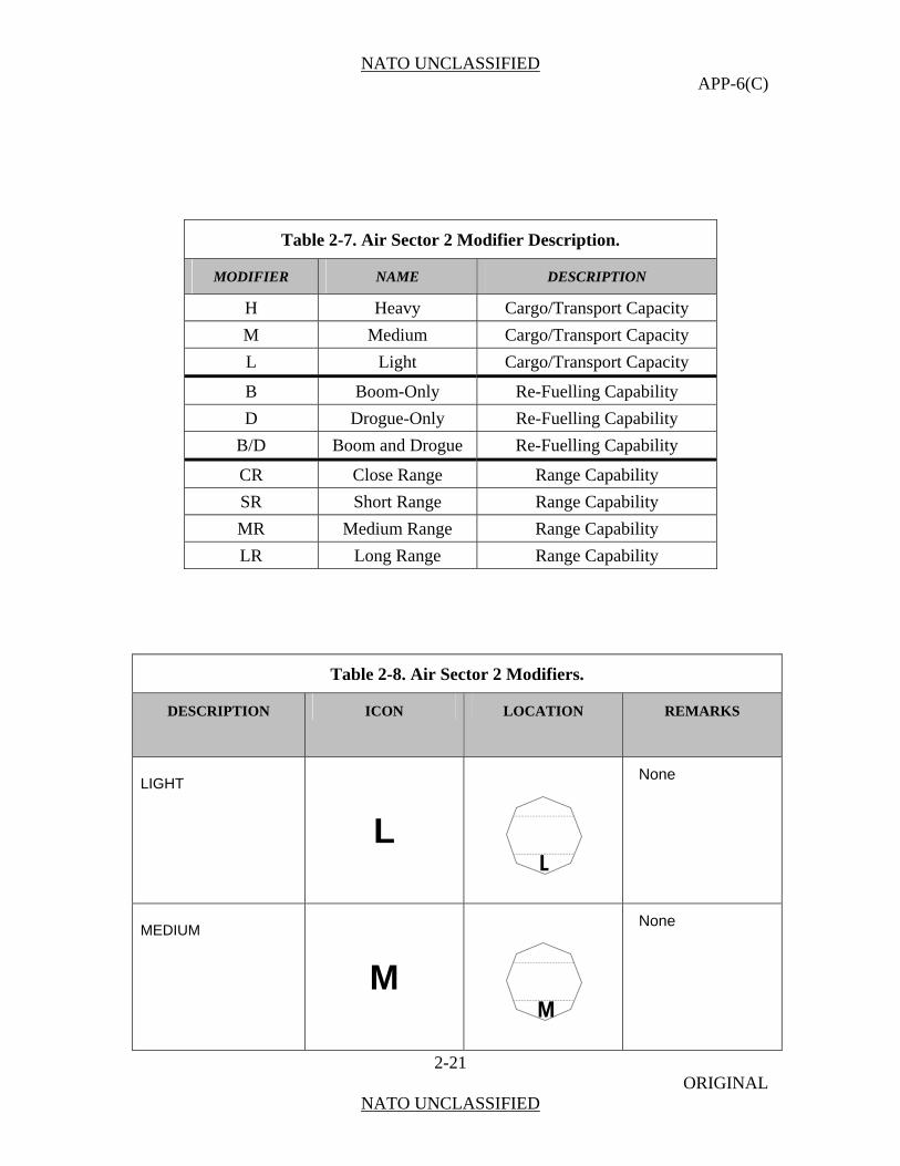
0213. Sector 2 modifiers are placed below the icon (Figure 2-5) and denote cargo, transport, or refuelling capacity (see Table 2-7). Table 2-8 shows sector 2 modifiers for air symbols.
Figure 2-5. Sector 2 Modifier Placement.
NATO UNCLASSIFIED APP-6(C)
2-21 ORIGINAL
NATO UNCLASSIFIED
Table 2-7. Air Sector 2 Modifier Description.
MODIFIER NAME DESCRIPTION
H Heavy Cargo/Transport Capacity
M Medium Cargo/Transport Capacity
L Light Cargo/Transport Capacity
B Boom-Only Re-Fuelling Capability
D Drogue-Only Re-Fuelling Capability
B/D Boom and Drogue Re-Fuelling Capability
CR Close Range Range Capability
SR Short Range Range Capability
MR Medium Range Range Capability
LR Long Range Range Capability
Table 2-8. Air Sector 2 Modifiers.
DESCRIPTION ICON LOCATION REMARKS
LIGHT
L
L
None
MEDIUM
M
M
None

NATO UNCLASSIFIED APP-6(C)
2-22 ORIGINAL
NATO UNCLASSIFIED
Table 2-8. Air Sector 2 Modifiers.
DESCRIPTION ICON LOCATION REMARKS
HEAVY
H
H
None
BOOM-ONLY
B B
Use with tankers only
DROGUE-ONLY
D D
Use with tankers only
BOOM AND DROGUE
B/D B/D
Use with tankers only
CLOSE RANGE
CR CR
None
NATO UNCLASSIFIED APP-6(C)
2-23 ORIGINAL
NATO UNCLASSIFIED
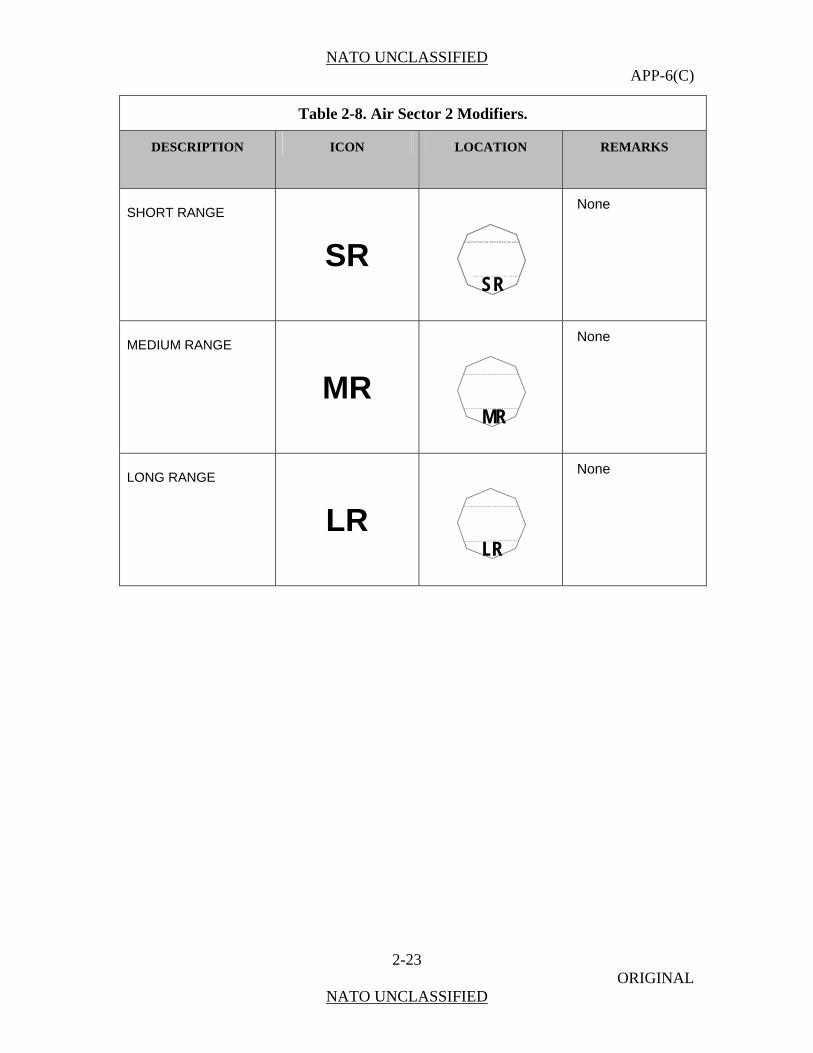
Table 2-8. Air Sector 2 Modifiers.
DESCRIPTION ICON LOCATION REMARKS
SHORT RANGE
SR SR
None
MEDIUM RANGE
MR
MR
None
LONG RANGE
LR
LR
None
NATO UNCLASSIFIED APP-6(C)
2-24 ORIGINAL
NATO UNCLASSIFIED
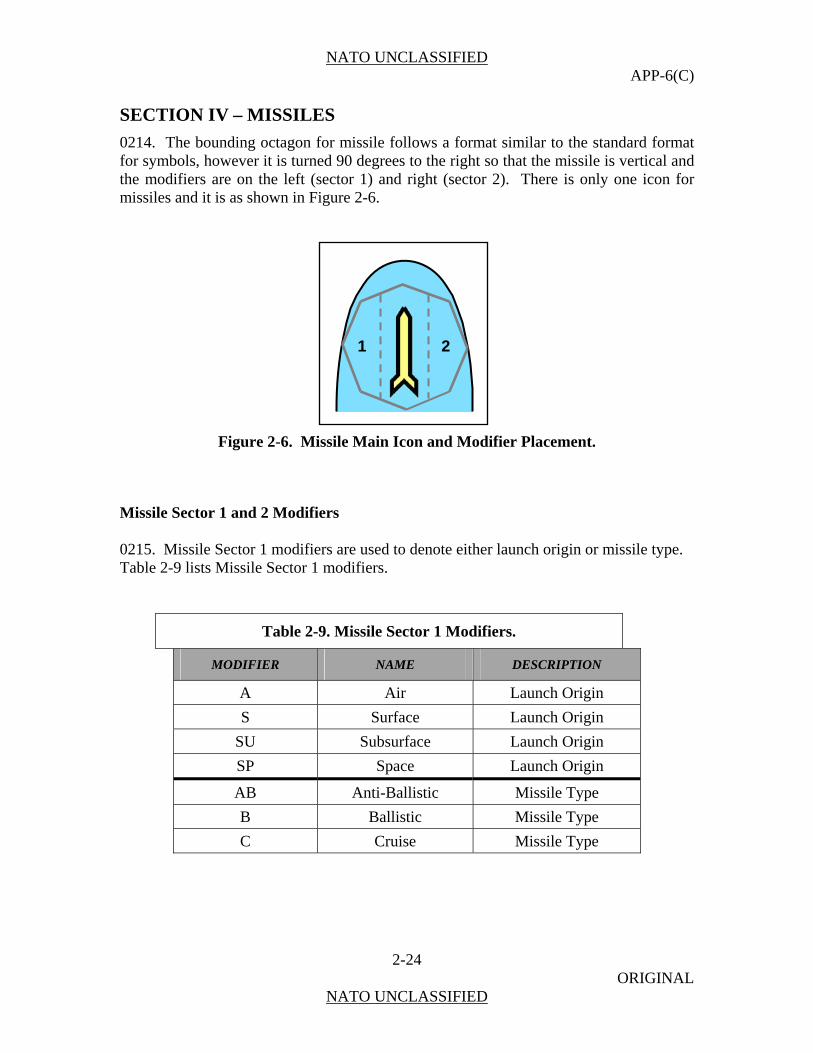
SECTION IV – MISSILES
0214. The bounding octagon for missile follows a format similar to the standard format for symbols, however it is turned 90 degrees to the right so that the missile is vertical and the modifiers are on the left (sector 1) and right (sector 2). There is only one icon for missiles and it is as shown in Figure 2-6.
Figure 2-6. Missile Main Icon and Modifier Placement.
Missile Sector 1 and 2 Modifiers 0215. Missile Sector 1 modifiers are used to denote either launch origin or missile type. Table 2-9 lists Missile Sector 1 modifiers.
Table 2-9. Missile Sector 1 Modifiers.
MODIFIER NAME DESCRIPTION
A ir n A Launch Origi
S e Surfac Launch Origin
SU e Subsurfac Launch Origin
SP e Spac Launch Origin
AB ic e Anti-Ballist Missile Typ
B ic e Ballist Missile Typ
C e e Cruis Missile Typ
1 2
NATO UNCLASSIFIED APP-6(C)
2-25 ORIGINAL
NATO UNCLASSIFIED
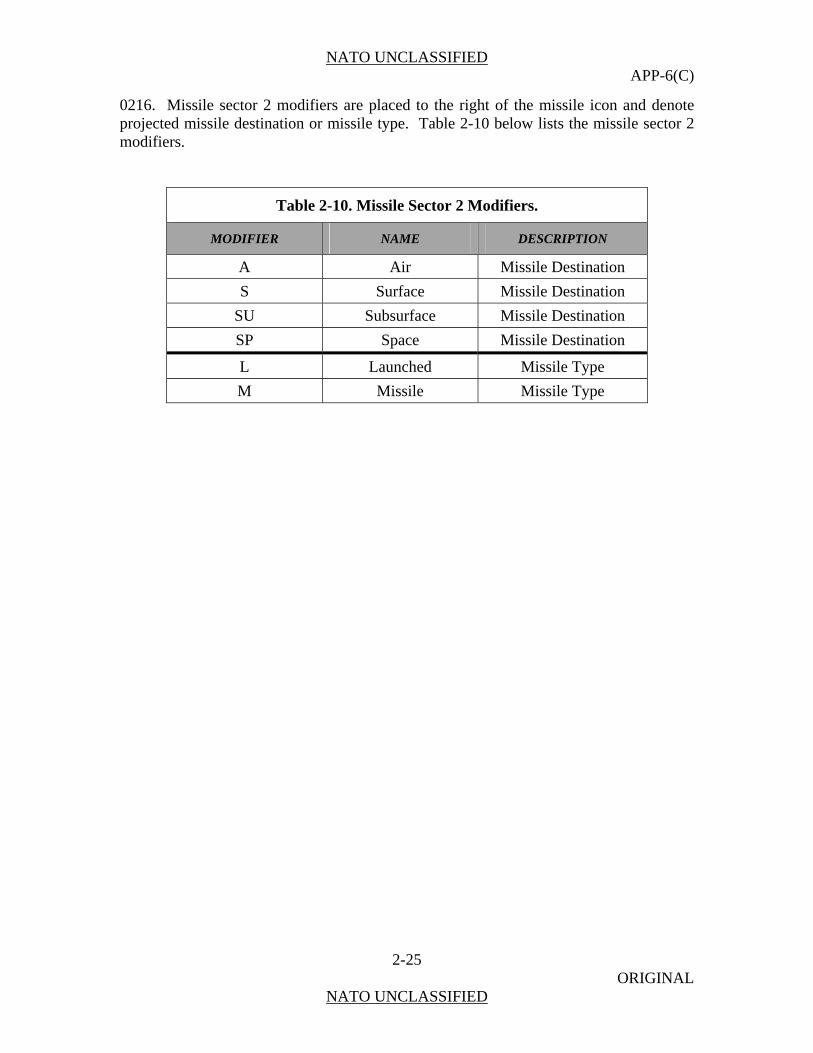
0216. Missile sector 2 modifiers are placed to the right of the missile icon and denote projected missile destination or missile type. Table 2-10 below lists the missile sector 2 modifiers.
Table 2-10. Missile Sector 2 Modifiers.
MODIFIER NAME DESCRIPTION
A Air Missile Destination
S Surface Missile Destination
SU Subsurface Missile Destination
SP Space Missile Destination
L Launched Missile Type
M Missile Missile Type

NATO UNCLASSIFIED APP-6(C)
2-26 ORIGINAL
NATO UNCLASSIFIED
(INTENTIONALLY BLANK)
NATO UNCLASSIFIED APP-6(C)
3-1 ORIGINAL
NATO UNCLASSIFIED
CHAPTER 3
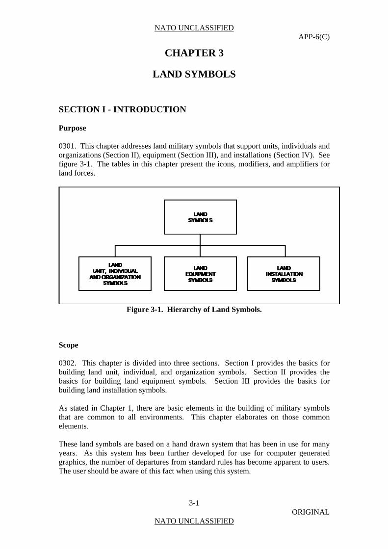
LAND SYMBOLS SECTION I - INTRODUCTION Purpose 0301. This chapter addresses land military symbols that support units, individuals and organizations (Section II), equipment (Section III), and installations (Section IV). See figure 3-1. The tables in this chapter present the icons, modifiers, and amplifiers for land forces.
Figure 3-1. Hierarchy of Land Symbols.
Scope 0302. This chapter is divided into three sections. Section I provides the basics for building land unit, individual, and organization symbols. Section II provides the basics for building land equipment symbols. Section III provides the basics for building land installation symbols. As stated in Chapter 1, there are basic elements in the building of military symbols that are common to all environments. This chapter elaborates on those common elements. These land symbols are based on a hand drawn system that has been in use for many years. As this system has been further developed for use for computer generated graphics, the number of departures from standard rules has become apparent to users. The user should be aware of this fact when using this system.
NATO UNCLASSIFIED APP-6(C)
3-2 ORIGINAL
NATO UNCLASSIFIED
Section II - Land Unit, Individual, and Organization Symbols General 0303. This section establishes a single standard for developing land unit, individual, and organization symbols. A unit is a military element whose structure is prescribed by a competent authority. Individuals and organizations are civilian based. This section includes a wide variety of icons, modifiers, and amplifiers for building a wide variety of symbols. However, no attempt has been made to depict all possible combinations. Rather, a standard method for constructing symbols is presented. Once the user is familiar with the prescribed system, any desired symbol can be developed using the logical sequence provided in this chapter. The symbols shown in this chapter are adequate for depicting all standard identities for units, individuals, and organizations. When representing unorthodox units, individuals, and organizations, select the most appropriate symbol contained herein. Avoid using any symbols or combinations and modifications of symbols that differ from those in this publication. If, after searching doctrinal icons and modifiers, it is necessary to create a new symbol, explain the symbol in an accompanying legend. Computer-generated systems may have difficulty in passing non-standard symbols. Composition of Unit, Individual, and Organization Symbols
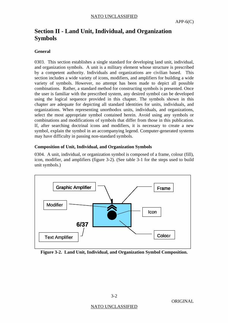
0304. A unit, individual, or organization symbol is composed of a frame, colour (fill), icon, modifier, and amplifiers (figure 3-2). (See table 3-1 for the steps used to build unit symbols.)
Figure 3-2. Land Unit, Individual, and Organization Symbol Composition.
Frame Graphic Amplifier
A
H
Color
Frame Graphic Amplifier
A
H
Color
Modifier
Text Amplifier
6/37
Icon
Frame Graphic Amplifier
A
H
A
H
Color
Frame Graphic Amplifier
A
H
Colour
Modifier
Text Amplifier
6/37
Icon

NATO UNCLASSIFIED APP-6(C)
3-3 ORIGINAL
NATO UNCLASSIFIED
Table 3-1. Building Unit, Individual, and Organization Symbols.
Step No. Step Example
Step 1. Choose the frame according to standard identity.
Land Unit Frame Shapes and Standard Identity
STANDARDIDENTITY
FRAME
PENDINGFRIENDLY HOSTILE NEUTRAL UNKNOWNASSUMED
FRIENDSUSPECT
STANDARDIDENTITY
FRAMEFRAME
PENDINGPENDINGFRIENDLYFRIENDLY HOSTILE HOSTILE NEUTRAL NEUTRAL UNKNOWNUNKNOWNASSUMED
FRIENDASSUMED
FRIENDSUSPECTSUSPECT
Step 2. Choose and add main sector icon.
Step 3. Choose and add a modifier in either sector 1 or sector 2 if applicable or deemed necessary for visualization.
Step 4. Choose and add a modifier in either sector 1 or sector 2 if applicable or deemed necessary for visualization. NOTE: Only one modifier is permitted per modifier position.
NATO UNCLASSIFIED APP-6(C)
3-4 ORIGINAL
NATO UNCLASSIFIED
Land Unit Icon, Modifier, and Amplifier Fields
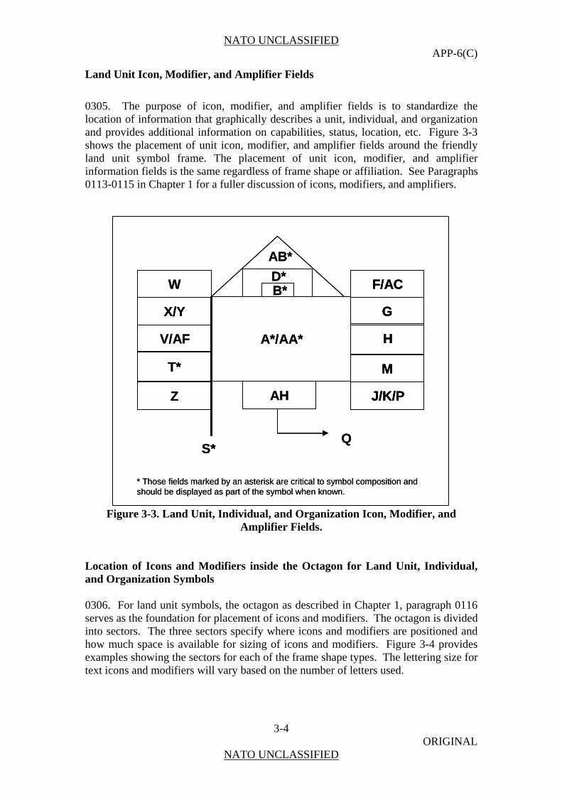
0305. The purpose of icon, modifier, and amplifier fields is to standardize the location of information that graphically describes a unit, individual, and organization and provides additional information on capabilities, status, location, etc. Figure 3-3 shows the placement of unit icon, modifier, and amplifier fields around the friendly land unit symbol frame. The placement of unit icon, modifier, and amplifier information fields is the same regardless of frame shape or affiliation. See Paragraphs 0113-0115 in Chapter 1 for a fuller discussion of icons, modifiers, and amplifiers.
W
X/Y
V/AF
T*
Z AH
F/AC
G
H
M
J/K/P
B*D*
QS*
A*/AA*
AB*
* Those fields marked by an asterisk are critical to symbol composition and should be displayed as part of the symbol when known.
W
X/Y
V/AF
T*
Z AH
F/AC
G
H
M
J/K/P
F/AC
G
H
M
J/K/P
B*D*
QS*
A*/AA*
AB*
* Those fields marked by an asterisk are critical to symbol composition and should be displayed as part of the symbol when known.
Figure 3-3. Land Unit, Individual, and Organization Icon, Modifier, and
Amplifier Fields. Location of Icons and Modifiers inside the Octagon for Land Unit, Individual, and Organization Symbols 0306. For land unit symbols, the octagon as described in Chapter 1, paragraph 0116 serves as the foundation for placement of icons and modifiers. The octagon is divided into sectors. The three sectors specify where icons and modifiers are positioned and how much space is available for sizing of icons and modifiers. Figure 3-4 provides examples showing the sectors for each of the frame shape types. The lettering size for text icons and modifiers will vary based on the number of letters used.
NATO UNCLASSIFIED APP-6(C)
3-5 ORIGINAL
NATO UNCLASSIFIED
FRIENDLY HOSTILE
NEUTRAL UNKNOWN
MAIN
1
2
MAIN
1
2
MAIN
1
2
MAIN
1
2
FRIENDLY HOSTILE
NEUTRAL UNKNOWN
MAIN
1
2
MAIN
1
2
MAIN
1
2
MAIN
1
2
MAIN
1
2
MAIN
1
2
MAIN
1
2
MAIN
1
2
MAIN
1
2
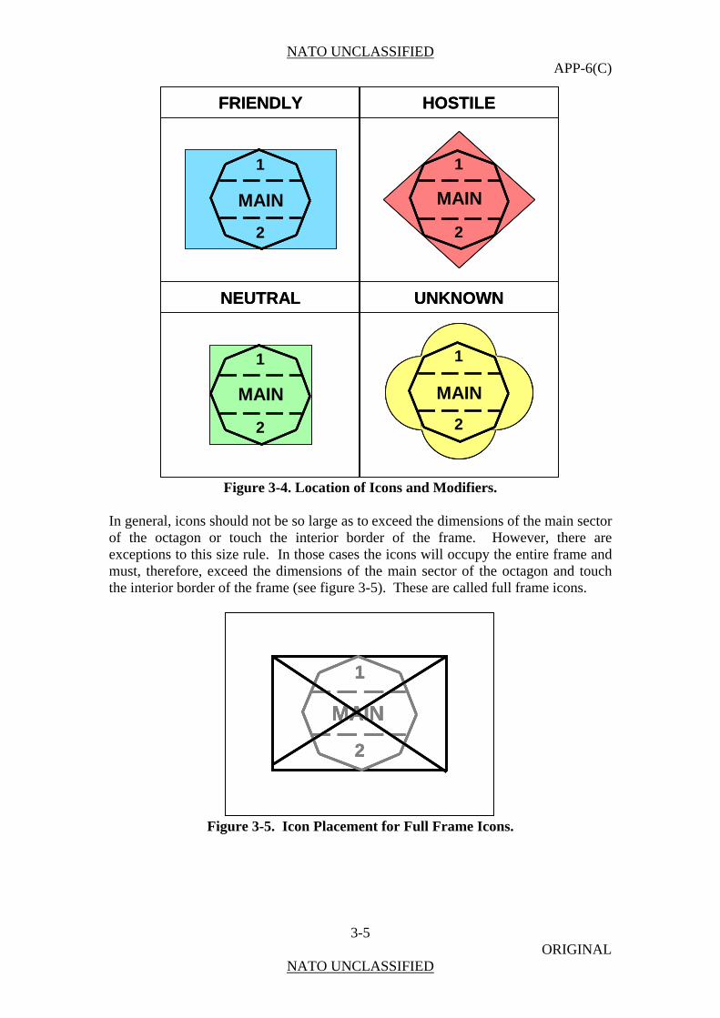
Figure 3-4. Location of Icons and Modifiers.
In general, icons should not be so large as to exceed the dimensions of the main sector of the octagon or touch the interior border of the frame. However, there are exceptions to this size rule. In those cases the icons will occupy the entire frame and must, therefore, exceed the dimensions of the main sector of the octagon and touch the interior border of the frame (see figure 3-5). These are called full frame icons.
MAIN
1
2
MAIN
1
2
MAIN
1
2
Figure 3-5. Icon Placement for Full Frame Icons.

NATO UNCLASSIFIED APP-6(C)
3-6 ORIGINAL
NATO UNCLASSIFIED
Icon, Modifier, and Amplifier Fields
0307. See paragraph 114 in Chapter 1 for a description of and more information on amplifiers. Table 3-2 provides a description of each of the unit symbol amplifying information fields as shown in figure 3-2. See Annex A (TBD) for examples of unit symbols with multiple fields that are filled in.
Table 3-2. Description of Icon, Modifier, and Amplifier Fields for Unit Symbols.
Field Field Title Description Text/Graphic
A Icon(s) Basic branch or functional symbol which can include capability modifiers.
Both
B Echelon A symbol modifier that denotes the size of a unit .
Both
D Task Force A symbol placed over the echelon indicator to denote a task-organized unit.
Graphic
F Reinforced or Detached
Indicates whether a unit is reinforced (+), reduced (-), or reinforced and reduced (+).
Text
G Staff Comments Free text. Can be used by staff for information required by commander.
Text
H Additional Information Free text. Text
J Evaluation Rating Degree of confidence that may be placed on the information represented by the symbol. It is shown as one letter and one number made up of Reliability of Source and Credibility of Information. (STANAG 2511). Reliability of Source: A. Completely reliable B. Usually reliable C. Fairly reliable D. Not usually reliable E. Unreliable F. Reliability cannot be judged. Credibility of Information: 1. Confirmed by other sources 2. Probably true 3. Possibly true 4. Doubtful 5. Improbable 6. Truth cannot be judged.
Text
K Combat Effectiveness Effectiveness of unit or equipment displayed. 1. Fully operational 2. Substantially operational 3. Marginally operational 4. Not operational
Text
M Higher Formation Number or title of higher echelon command of unit being displayed.1
Text

NATO UNCLASSIFIED APP-6(C)
3-7 ORIGINAL
NATO UNCLASSIFIED
Table 3-2. Description of Icon, Modifier, and Amplifier Fields for Unit Symbols.
Field Field Title Description Text/Graphic
P Identification, Friend-or-Foe (IFF)/Selective Identification Feature (SIF)
Identification modes and codes. Text
Q Direction of Movement Arrow/Offset Location Indicator
With arrow, it denotes the direction symbol is moving or will move. Without arrow, it is used to denote precise location or to declutter, except headquarters.
Graphic
S Headquarters Staff Indicator/Offset Location Indicator
Identifies unit symbol as a headquarters or used to indicate precise location or to declutter.
Graphic
T Unique Designation An alphanumeric designator that uniquely identifies a particular unit (designation).
Text
V Type of Equipment Identifies unique designation (such as M-2 for infantry fighting vehicle).
Text
W Date-Time Group An alphanumeric designator for displaying a date-time group (DDHHMMSSZMONYY) or “O/O” for on order. The date-time group is composed of a group of six numeric digits with a time zone suffix and the standardized three-letter abbreviation for the month followed by two digits. The first pair of digits represents the day; the second pair, the hour; the third pair, the minutes. The last two digits of the year are after the month. For automated systems, two digits may be added before the time zone suffix and after the minutes to designate seconds.
Text
X Altitude/Depth Altitude as displayed on the global positioning system (GPS).
Text
Y Location Latitude and longitude; grid coordinates. Text
Z Speed Displays speed in nautical miles per hour or kilometres per hour.
Text
AA Named C2 Headquarters
This field applies to named commands such as SHAPE, SACLANT, ARRC, ISAF or joint, multinational, or coalition commands such as CJTF, JTF, MJTF.
Text
AB Feint or Dummy Indicator
Indicates that it is a dummy or a feint for deception purposes.
Graphic
AC Country Indicator A three-letter code that indicates the country of origin of the unit (STANAG 1059). In stability activities, this field can be used for factions or groups.
Text
AF Common Identifier Example: Paladin for the M109A6 howitzer or Leopard for the KPz-70 tank. (Use NATO code name for hostile common identifiers.)
Text
AH Headquarters Element Indicates what type of element of a headquarters is being represented, such as TOC, MAIN.
Text

NATO UNCLASSIFIED APP-6(C)
3-8 ORIGINAL
NATO UNCLASSIFIED
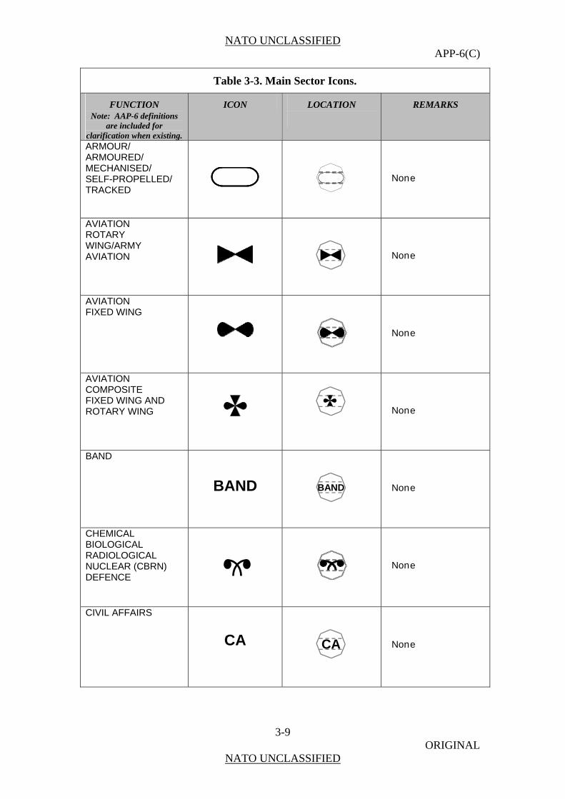
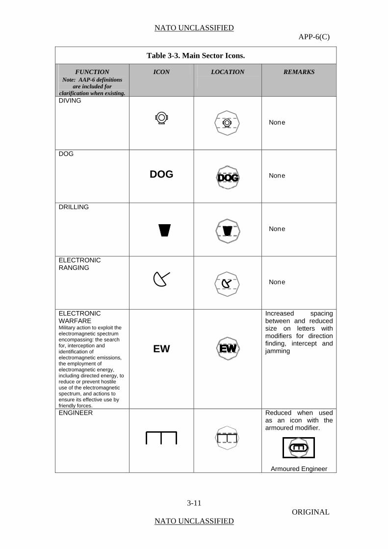
Unit Main Sector Icons 0308. Icons in the main sector (figure 3-6) normally reflect the main function of the symbol, but in some cases can also reflect modifying information (e.g., armoured engineers). Table 3-3 below shows the icons for use in land unit symbols in the main sector of the A field of the symbol. In most cases, the dimensions of the icon will be sized to occupy as much area in the main sector as is available. However, in some cases the icon may be reduced to allow more room for modifiers for better recognition or to allow for one icon to modify another (e.g., armoured/self-propelled artillery).
MAIN
1
2
MAIN
1
2
Figure 3-6. Main Sector Icons.
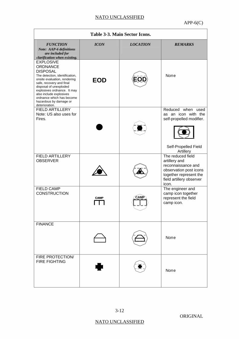
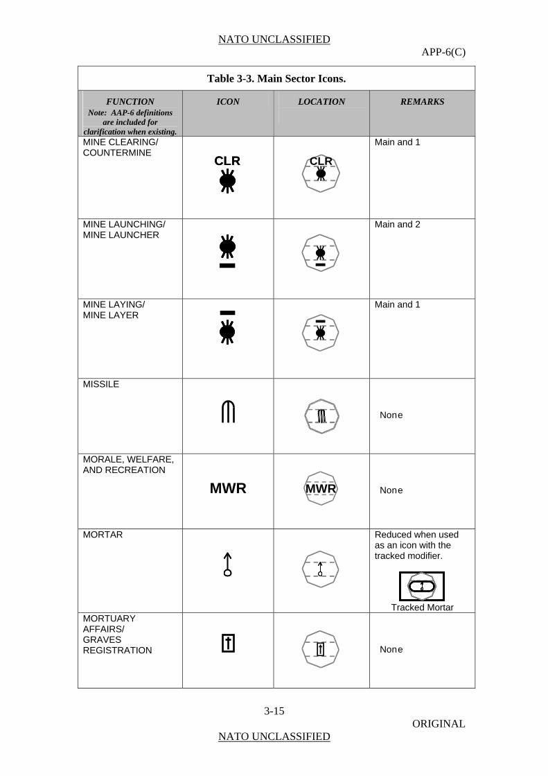
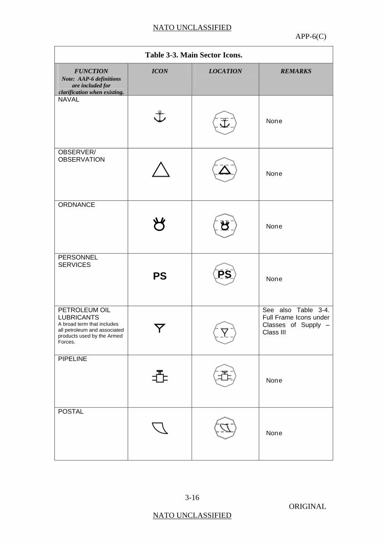
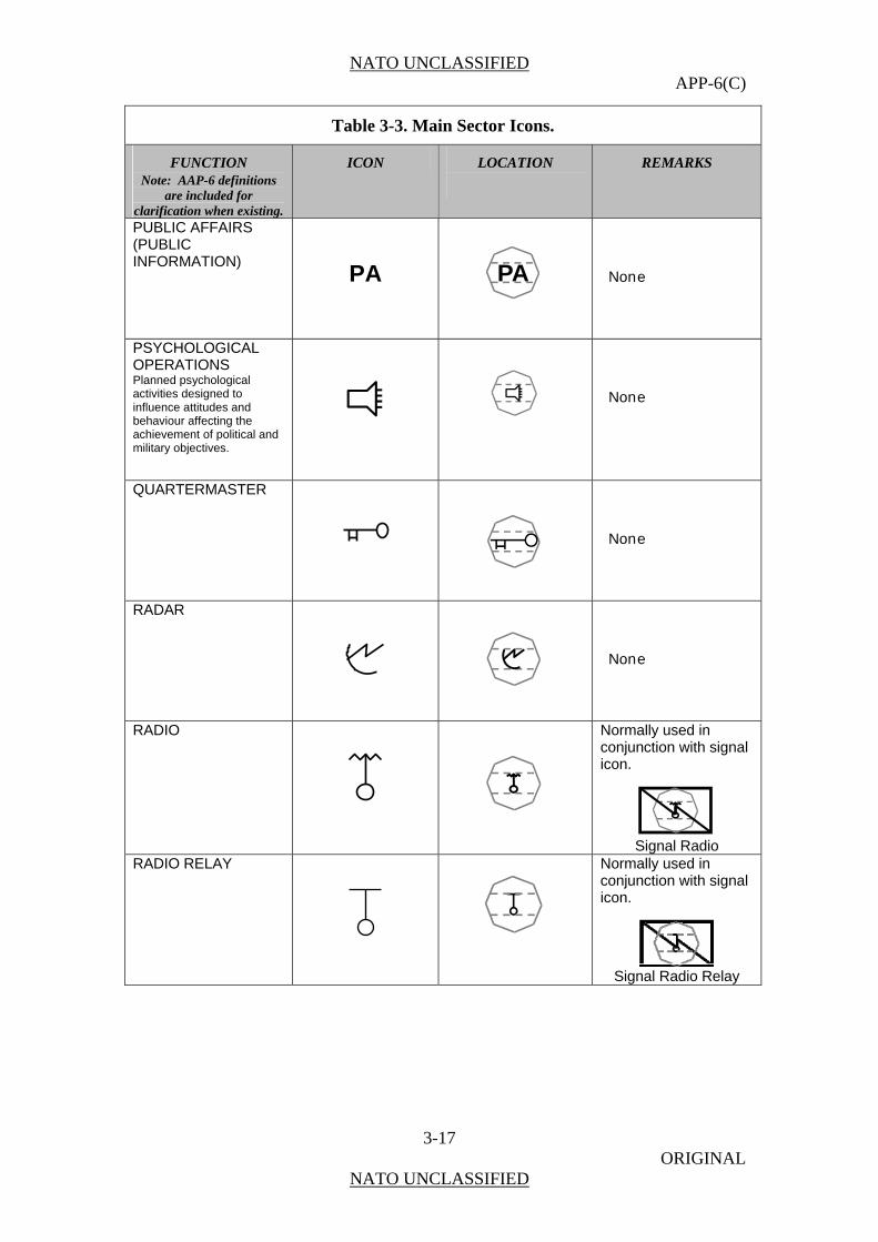
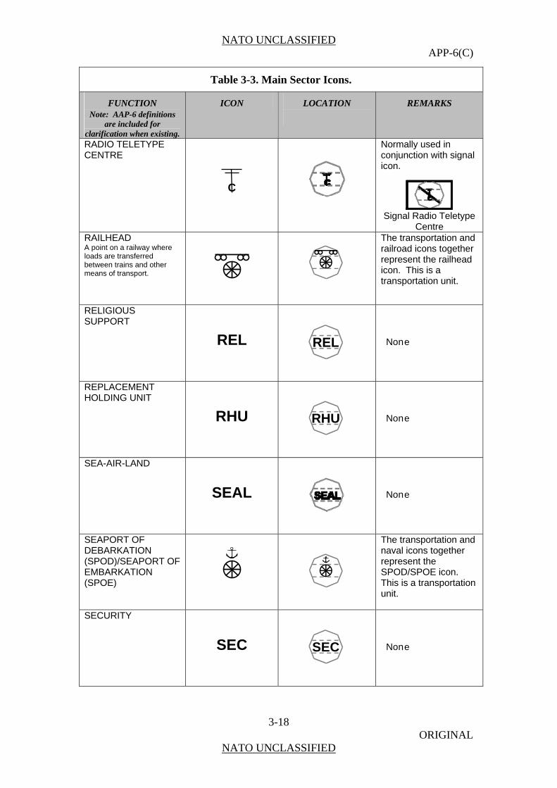
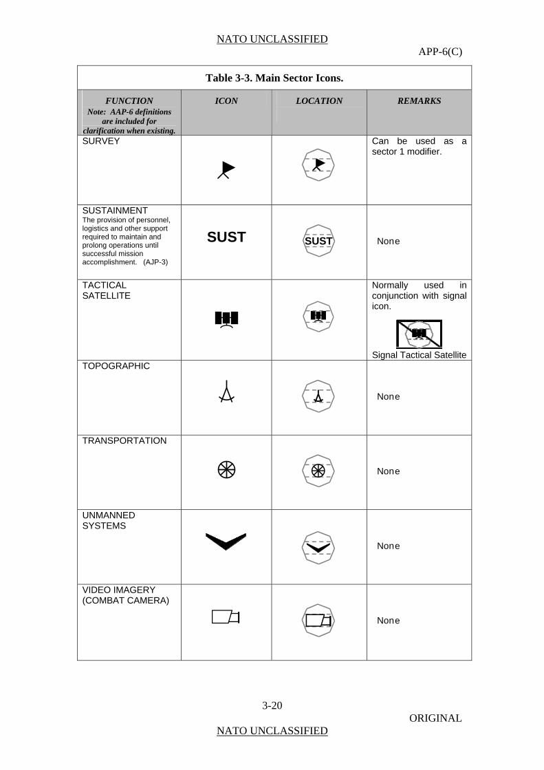
Table 3-3. Main Sector Icons.
FUNCTION Note: AAP-6 definitions
are included for clarification when existing.
ICON LOCATION
REMARKS
ADMINISTRATIVE
ADM
None
AIR TRAFFIC SERVICES / AIRFIELD OPERATIONS
None
AIRPORT OF DEBARKATION (APOD)/ AIRPORT OF EMBARKATION (APOE)
The transportation and runway icons together represent the APOD / APOE icon. This is a transportation unit.
AMMUNITION
See also Table 3-4. Full Frame Icons under Classes of Supply – Class V
NATO UNCLASSIFIED APP-6(C)
3-9 ORIGINAL
NATO UNCLASSIFIED
Table 3-3. Main Sector Icons.
FUNCTION Note: AAP-6 definitions
are included for clarification when existing.
ICON LOCATION
REMARKS
ARMOUR/ ARMOURED/ MECHANISED/ SELF-PROPELLED/ TRACKED
None
AVIATION ROTARY WING/ARMY AVIATION
None
AVIATION FIXED WING
None
AVIATION COMPOSITE FIXED WING AND ROTARY WING
None
BAND
BAND
BAND
None
CHEMICAL BIOLOGICAL RADIOLOGICAL NUCLEAR (CBRN) DEFENCE
None
CIVIL AFFAIRS
CA
CA
None

NATO UNCLASSIFIED APP-6(C)
3-10 ORIGINAL
NATO UNCLASSIFIED
Table 3-3. Main Sector Icons.
FUNCTION Note: AAP-6 definitions
are included for clarification when existing.
ICON LOCATION
REMARKS
CIVIL-MILITARY-COOPERATION
None
COMBAT
CBT
None
COMBAT SERVICE SUPPORT The support provided to combat forces, primarily in the fields of administration and logistics.
CSS
None
COMBAT SUPPORT (MANOEUVRE ENHANCEMENT) Integrates the complementary and reinforcing capabilities of the force protection, manoeuvre and fires, and sustainment joint functions, tasks, and systems to enhance freedom of action into a single unit.
None
COMBINED ARMS A unit in which infantry and armour units are assigned together to create a combined arms effect.
None
COUNTER- INTELLIGENCE
CI
None
CRIMINAL INVESTIGATION DIVISION
CID
None
NATO UNCLASSIFIED APP-6(C)
3-11 ORIGINAL
NATO UNCLASSIFIED
Table 3-3. Main Sector Icons.
FUNCTION Note: AAP-6 definitions
are included for clarification when existing.
ICON LOCATION
REMARKS
DIVING
None
DOG
DOG
None
DRILLING
None
ELECTRONIC RANGING
None
ELECTRONIC WARFARE Military action to exploit the electromagnetic spectrum encompassing: the search for, interception and identification of electromagnetic emissions, the employment of electromagnetic energy, including directed energy, to reduce or prevent hostile use of the electromagnetic spectrum, and actions to ensure its effective use by friendly forces.
EW
Increased spacing between and reduced size on letters with modifiers for direction finding, intercept and jamming
ENGINEER
Reduced when used as an icon with the armoured modifier.
Armoured Engineer
NATO UNCLASSIFIED APP-6(C)
3-12 ORIGINAL
NATO UNCLASSIFIED
Table 3-3. Main Sector Icons.
FUNCTION Note: AAP-6 definitions
are included for clarification when existing.
ICON LOCATION
REMARKS
EXPLOSIVE ORDNANCE DISPOSAL The detection, identification, onsite evaluation, rendering safe, recovery and final disposal of unexploded explosives ordnance. It may also include explosives ordnance which has become hazardous by damage or deterioration.
EOD
EOD
None
FIELD ARTILLERY Note: US also uses for Fires.
Reduced when used as an icon with the self-propelled modifier.
Self-Propelled Field Artillery
FIELD ARTILLERY OBSERVER
The reduced field artillery and reconnaissance and observation post icons together represent the field artillery observer icon.
FIELD CAMP CONSTRUCTION
CAMPCAMP
CAMP
The engineer and camp icon together represent the field camp icon.
FINANCE
None
FIRE PROTECTION/ FIRE FIGHTING
None

NATO UNCLASSIFIED APP-6(C)
3-13 ORIGINAL
NATO UNCLASSIFIED
Table 3-3. Main Sector Icons.
FUNCTION Note: AAP-6 definitions
are included for clarification when existing.
ICON LOCATION
REMARKS
GEOSPATIAL SUPPORT/ GEOSPATIAL INFORMATION SUPPORT
GEO
GEO
None
INFORMATION OPERATIONS
IO
IO
None
INTERROGATION
IPW
IPW
None
JOINT FIRE SUPPORT
JFS
JFS
None
JUDGE ADVOCATE GENERAL
JAG
JAG
None
LABOUR
None
LAUNDRY/BATH
None

NATO UNCLASSIFIED APP-6(C)
3-14 ORIGINAL
NATO UNCLASSIFIED
Table 3-3. Main Sector Icons.
FUNCTION Note: AAP-6 definitions
are included for clarification when existing.
ICON LOCATION
REMARKS
LIAISON That contact or intercommunication maintained between elements of military forces to ensure mutual understanding and unity of purpose and action.
LO
LO
None
MAINTENANCE All actions taken to retain equipment in or to restore it to a specified condition, including inspection, testing, servicing, classification as to serviceability, repair, rebuilding and reclamation.
None
MATERIEL
MAT
Must be used in conjunction with the supply icon.
METEOROLOGICAL
MET
MET
None
MILITARY INTELLIGENCE
MI
MI
None
MILITARY POLICE
MP
MP
None
MINE In land mine warfare, an explosive ammunition designed to be placed under, on or near the ground or other surface area and to be actuated by the presence, proximity or contact of a person, land vehicle, aircraft or boat, including landing craft.
None
NATO UNCLASSIFIED APP-6(C)
3-15 ORIGINAL
NATO UNCLASSIFIED
Table 3-3. Main Sector Icons.
FUNCTION Note: AAP-6 definitions
are included for clarification when existing.
ICON LOCATION
REMARKS
MINE CLEARING/ COUNTERMINE
CLRCLR
CLR
Main and 1
MINE LAUNCHING/ MINE LAUNCHER
Main and 2
MINE LAYING/ MINE LAYER
Main and 1
MISSILE
None
MORALE, WELFARE, AND RECREATION
MWR
MWR
None
MORTAR
Reduced when used as an icon with the tracked modifier.
Tracked Mortar
MORTUARY AFFAIRS/ GRAVES REGISTRATION
None
NATO UNCLASSIFIED APP-6(C)
3-16 ORIGINAL
NATO UNCLASSIFIED
Table 3-3. Main Sector Icons.
FUNCTION Note: AAP-6 definitions
are included for clarification when existing.
ICON LOCATION
REMARKS
NAVAL
None
OBSERVER/ OBSERVATION
None
ORDNANCE
None
PERSONNEL SERVICES
PS
PS
None
PETROLEUM OIL LUBRICANTS A broad term that includes all petroleum and associated products used by the Armed Forces.
See also Table 3-4. Full Frame Icons under Classes of Supply – Class III
PIPELINE
None
POSTAL
None
NATO UNCLASSIFIED APP-6(C)
3-17 ORIGINAL
NATO UNCLASSIFIED
Table 3-3. Main Sector Icons.
FUNCTION Note: AAP-6 definitions
are included for clarification when existing.
ICON LOCATION
REMARKS
PUBLIC AFFAIRS (PUBLIC INFORMATION)
PA
PA
None
PSYCHOLOGICAL OPERATIONS Planned psychological activities designed to influence attitudes and behaviour affecting the achievement of political and military objectives.
None
QUARTERMASTER
None
RADAR
None
RADIO
Normally used in conjunction with signal icon.
Signal Radio
RADIO RELAY
Normally used in conjunction with signal icon.
Signal Radio Relay
NATO UNCLASSIFIED APP-6(C)
3-18 ORIGINAL
NATO UNCLASSIFIED
Table 3-3. Main Sector Icons.
FUNCTION Note: AAP-6 definitions
are included for clarification when existing.
ICON LOCATION
REMARKS
RADIO TELETYPE CENTRE
Normally used in conjunction with signal icon.
Signal Radio Teletype
Centre RAILHEAD A point on a railway where loads are transferred between trains and other means of transport.
The transportation and railroad icons together represent the railhead icon. This is a transportation unit.
RELIGIOUS SUPPORT
REL
REL
None
REPLACEMENT HOLDING UNIT
RHU
RHU
None
SEA-AIR-LAND
SEAL
None
SEAPORT OF DEBARKATION (SPOD)/SEAPORT OF EMBARKATION (SPOE)
The transportation and naval icons together represent the SPOD/SPOE icon. This is a transportation unit.
SECURITY
SEC
SEC
None
C

NATO UNCLASSIFIED APP-6(C)
3-19 ORIGINAL
NATO UNCLASSIFIED
Table 3-3. Main Sector Icons.
FUNCTION Note: AAP-6 definitions
are included for clarification when existing.
ICON LOCATION
REMARKS
SECURITY POLICE (AIR)
SP
SP and fixed wing aviation icons together represent the security police (air) icon.
SENSOR
None
SHORE PATROL
SP
SP
None
SNIPER
None
SPECIAL FORCES Specially designated, organized, trained and equipped forces using operational techniques and modes of employment not standard to conventional forces. (APP-6) Note: These are land units.
SF
SF
None
SPECIAL OPERATIONS FORCES
SOF
SOF
None
SURVEILLANCE The systematic observation of aerospace, surface or subsurface areas, places, persons, or things, by visual, aural, electronic, photographic, or other means.
None
SP
NATO UNCLASSIFIED APP-6(C)
3-20 ORIGINAL
NATO UNCLASSIFIED
Table 3-3. Main Sector Icons.
FUNCTION Note: AAP-6 definitions
are included for clarification when existing.
ICON LOCATION
REMARKS
SURVEY
Can be used as a sector 1 modifier.
SUSTAINMENT The provision of personnel, logistics and other support required to maintain and prolong operations until successful mission accomplishment. (AJP-3)
SUST
SUST
None
TACTICAL SATELLITE
Normally used in conjunction with signal icon.
Signal Tactical Satellite
TOPOGRAPHIC
None
TRANSPORTATION
None
UNMANNED SYSTEMS
None
VIDEO IMAGERY (COMBAT CAMERA)
None
NATO UNCLASSIFIED APP-6(C)
3-21 ORIGINAL
NATO UNCLASSIFIED
Table 3-3. Main Sector Icons.
FUNCTION Note: AAP-6 definitions
are included for clarification when existing.
ICON LOCATION
REMARKS
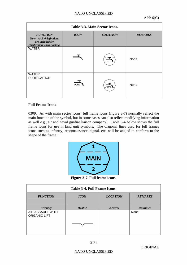
WATER
None
WATER PURIFICATION
PURE
None
Full Frame Icons 0309. As with main sector icons, full frame icons (figure 3-7) normally reflect the main function of the symbol, but in some cases can also reflect modifying information as well e.g., air and naval gunfire liaison company). Table 3-4 below shows the full frame icons for use in land unit symbols. The diagonal lines used for full frames icons such as infantry, reconnaissance, signal, etc. will be angled to conform to the shape of the frame.
MAIN
1
2
MAIN
1
2
Figure 3-7. Full frame icons.
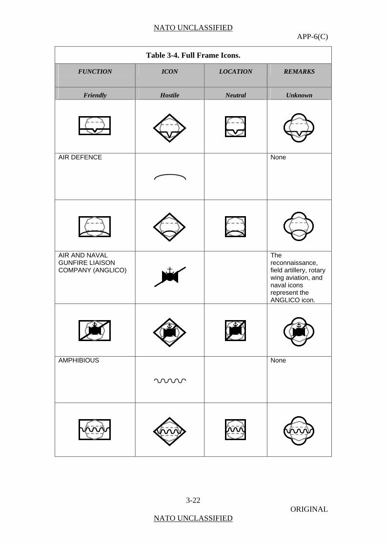
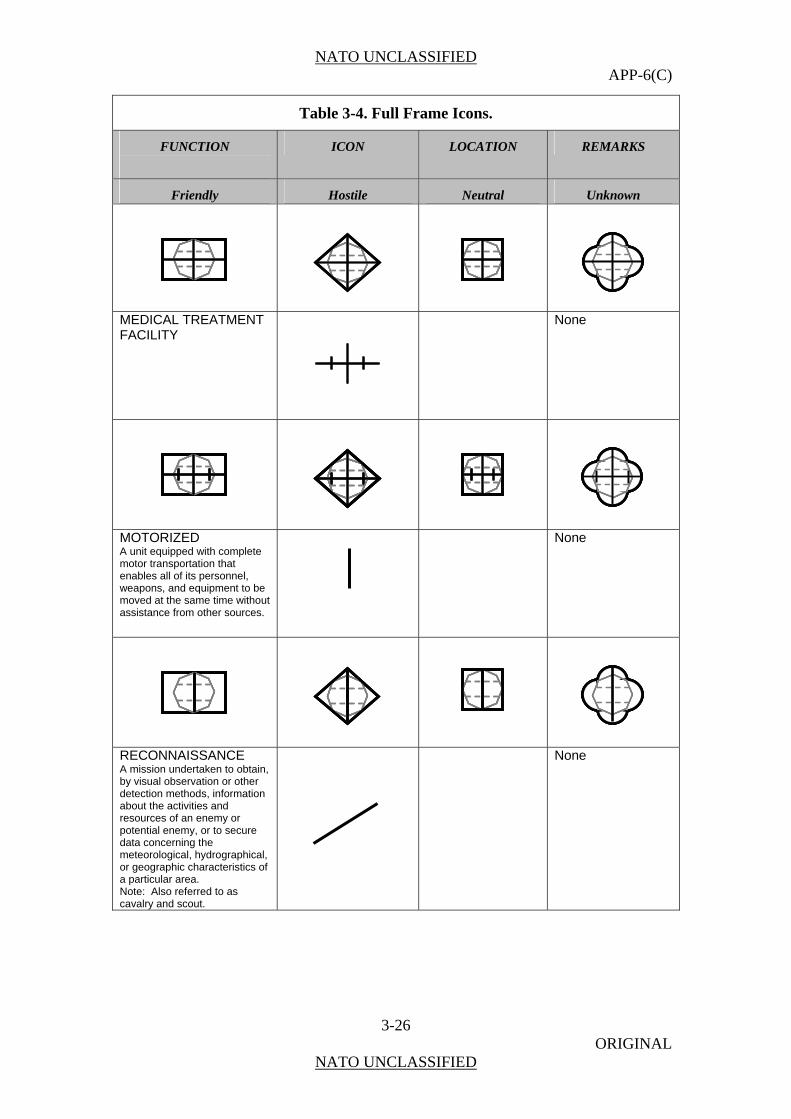
Table 3-4. Full Frame Icons.
FUNCTION
ICON LOCATION REMARKS
Friendly Hostile Neutral Unknown AIR ASSAULT WITH ORGANIC LIFT
None
PURE
NATO UNCLASSIFIED APP-6(C)
3-22 ORIGINAL
NATO UNCLASSIFIED
Table 3-4. Full Frame Icons.
FUNCTION
ICON LOCATION REMARKS
Friendly Hostile Neutral Unknown
AIR DEFENCE
None
AIR AND NAVAL GUNFIRE LIAISON COMPANY (ANGLICO)
The reconnaissance, field artillery, rotary wing aviation, and naval icons represent the ANGLICO icon.
AMPHIBIOUS
None

NATO UNCLASSIFIED APP-6(C)
3-23 ORIGINAL
NATO UNCLASSIFIED
Table 3-4. Full Frame Icons.
FUNCTION
ICON LOCATION REMARKS
Friendly Hostile Neutral Unknown ANALYSIS
Normally used in conjunction with the electronic warfare icon. Increased spacing between letters.
E W E W E W
ANTITANK/ ANTIARMOUR
None
BROADCAST TRANSMITTER ANTENNA
Can be used in conjunction with the psychological operations icon.
Psychological
Operations Broadcast
CORPS SUPPORT
None

NATO UNCLASSIFIED APP-6(C)
3-24 ORIGINAL
NATO UNCLASSIFIED
Table 3-4. Full Frame Icons.
FUNCTION
ICON LOCATION REMARKS
Friendly Hostile Neutral Unknown
DIRECTION FINDING
Normally used in conjunction with the electronic warfare icon.
Electronic Warfare Direction Finding
HEADQUARTERS OR HEADQUARTERS ELEMENT
None
INFANTRY
None

NATO UNCLASSIFIED APP-6(C)
3-25 ORIGINAL
NATO UNCLASSIFIED
Table 3-4. Full Frame Icons.
FUNCTION
ICON LOCATION REMARKS
Friendly Hostile Neutral Unknown INTERCEPT (SEARCH AND RECORDING)
Normally used in conjunction with the electronic warfare icon
I Electronic Warfare
Intercept
JAMMING
Normally used in conjunction with the electronic warfare icon
Electronic Warfare
Jamming
MAIN GUN SYSTEM
None
MEDICAL
None
NATO UNCLASSIFIED APP-6(C)
3-26 ORIGINAL
NATO UNCLASSIFIED
Table 3-4. Full Frame Icons.
FUNCTION
ICON LOCATION REMARKS
Friendly Hostile Neutral Unknown
MEDICAL T ATMENT FACILITY
RE
None
MOTORIZEDA unit equipped th complete motor transportenables all of its personnel, weapons, and equipment to be moved at the same time without assistance from other sources.
None wi
ation that
RECONNAISSANCE A mission undertaken to obtain, by visual observation or other detection methods, information about the activities and resources of an enemy r potential enemydata concerning he meteorological, hydrographical, or geographic characteristics of a particular area. Note: Also referred to as cavalry and scout.
None
o, or to secure t

NATO UNCLASSIFIED APP-6(C)
3-27 ORIGINAL
NATO UNCLASSIFIED
Table 3-4. Full Frame Icons.
FUNCTION
ICON LOCATION REMARKS
Friendly Hostile Neutral Unknown
SEARCH (RECONNAISSANCE)
Normally used in conjunction with the electronic warfare icon
E W E W
Electronic Warfare Search
SIGNAL
N
one
SUPPLY
When used with Headquarters, also referred to as Service a n Headquarters and Service None
s i

NATO UNCLASSIFIED APP-6(C)
3-28 ORIGINAL
NATO UNCLASSIFIED
Table 3-4. Full Frame Icons.
FUNCTION
ICON LOCATION REMARKS
Friendly Hostile Neutral Unknown
NATO CLASSES OF SUPPLY
Note: These icons are also used in creating supply points. See Chapter 5, Control Measure Symbols.
Note: Use the same positioning for the supply icon as shown in the examples for supply.
Classes of Supply require the use of the supply icon in conjunction with the each different class and subclass type icons.
CLASS I Those items which are consumed by personnel or animals at the approximately
in rrain
uniform rate, irrespective of local changescombat or teonditions. c
Class I icon requ s the use of the supply icon in conjunction with the Roman
s
ire
numeral I icon to represent all of ClasI.
CLASS II Supplies for which allowances
ed by tables of
are establishorganisation and equipment.
Class II icon requires the use of the supply icon in conjunction with the Roman numeral II icon to represent all of ClasII.
s
CLASS III PETROLEUM, OIL AND LUBRICANFuels and lub
TS (POL)
ricants for all
purposes, except for operating aircraft or for use in weapons such as flame throwers.
Class III icon requires the use of the supply icon in conjunction with the POL icon.
CLASS IV hich initial issue
de
l issue lass II), such as additional
Supplies for wallowances are not prescribed by approved issue tables. Normally such supplies inclufortification and construction materials, as well as additional quantities of items identical to those authorized for initia(Cvehicles.
Class IV icon requires
represent all of Class IV.
the use of the supply icon in conjunction with the Roman numeral IV icon to
CLASS V AMMUNITION Ammunition, explosives and chemical agents of all types.
Class V icon requires the use of the supply icon in conjunction with the ammunitionicon.
IV
II
I

NATO UNCLASSIFIED APP-6(C)
3-29 ORIGINAL
NATO UNCLASSIFIED
Table 3-4. Full Frame Icons.
FUNCTION
ICON LOCATION REMARKS
Friendly Hostile Neutral Unknown MULTIPLE CLASSES OF SUPPLY
I&IV
The Multiple Classes of Supply icon requires the use of the supply icon in conjunction with the Roman numeral representation of classes of supply icons.
ALL CLASSES OF SUPPLY
ALL
The All Classes of Supply icon requires the use of the supplicon in conjunction with the all icon.
y
US CLASSES OF SUPPLY Note: See STANAG 2961, Classes of Supply of NATO Land Forces. It includes other systems for designating classes of supply to include a comparison with U classes (shown below). S
CLASS I (NATO CLASS I)
UBSISTENCE S
Class I subsistence icon requires the use of the supply icon inconjunction with the
subsistence icon.
CLASS II (NATO CLASS II)
G AND
CLOTHINEQUIPMENT
Class II clothing and equipment icon requires the use of the supply icon in conjunction with the quartermaster icon.
CLASS III ATO CLASS III)
UM, OIL AND L)
(NPETROLELUBRICANTS (PO
Class III icon requires the use of the supply icon in conjunction with the POL icon.
CLASS IV (NATO CLASS IV)
CTION
CONSTRUMATERIAL
Class IV constructionmaterial icon requirethe use of the supply
s
icon in conjunction with the engineer icon.
CLASS V (NATO CLASS V)
MMUNITION
A
Class V icon requires the use of the supply icon in conjunction with the ammunition icon.
ALL
I&IV
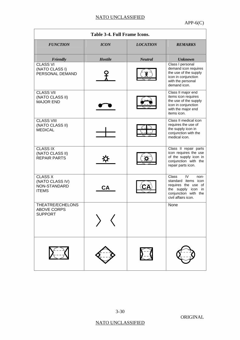
NATO UNCLASSIFIED APP-6(C)
3-30 ORIGINAL
NATO UNCLASSIFIED
Table 3-4. Full Frame Icons.
FUNCTION
ICON LOCATION REMARKS
Friendly Hostile Neutral Unknown CLASS VI (NATO CLASS I) PERSONAL DEMAND
Class I personal demand icon requires the use of the supplicon in conjunction with th
y
e personal demand icon.
CLASS VII (NATO CLASS II) MAJOR END
Class II major enditems icon requires the use of the supply icon in conjunction with the major enditems icon.
CLASS VIII (NATO CLASS II) MEDICAL
Class II medical icorequires the use of the supply icon in conjunction with themedical icon.
n
CLASS IX (NATO CLASS II) REPAIR PARTS
Class II repair partsicon requires the uof the supply iconconjunction with threpair parts ico
se in
e n.
CLASS X (NATO CLASS IV) NON-STANDARD
EMS IT
CA
Class IV non-standard items icon requires the use of the supply icon in conjunction with the civil affairs icon.
THEATRE/ECHELONS
ABOVE CORPS SUPPORT
None
CA

NATO UNCLASSIFIED APP-6(C)
3-31 ORIGINAL
NATO UNCLASSIFIED
Sector 1 Modifiers 0310. Sector 1 modifiers (Figure 3-8) depict additional information pertaining to the icon. Table 3-5 shows the modifiers for use in land unit symbols in sector 1 of the A field of the symbol.
MAIN
1
2
MAIN
1
2
Figure 3-8. Sector 1 Modifiers Placement.
Table 3-5. Sector 1 Modifiers.
FUNCTION ICON LOCATION REMARKS
AIRMOBILE/AIR ASSAULT (US ONLY)
None
AREA
AREA
AREA
None
ATTACK
A
A
Normally used with aviation.
A
Attack Aviation
BIOLOGICAL
B
B
Normally used with CBRN defence icon.
B
Biological CBRN
Defence

NATO UNCLASSIFIED APP-6(C)
3-32 ORIGINAL
NATO UNCLASSIFIED
Table 3-5. Sector 1 Modifiers.
FUNCTION ICON LOCATION REMARKS
BORDER BOR
BOR
None
BRIDGING
Normally used with engineer icon.
Engineer Bridging CHEMICAL
C
C
Normally used with CBRN defence icon.
C
Chemical CBRN
Defence CLOSE PROTECTION A unit that provides additional protection to important personnel.
CLP
CLP
None
COMBAT
CBT
CBT
None
COMMAND AND CONTROL
C2
C2
None
COMMUNICATIONS CONTINGENCY PACKAGE
CCP
CCP
Must be used in conjunction with the signal icon.
CCPCCP
Signal
Communications Contingency
Package
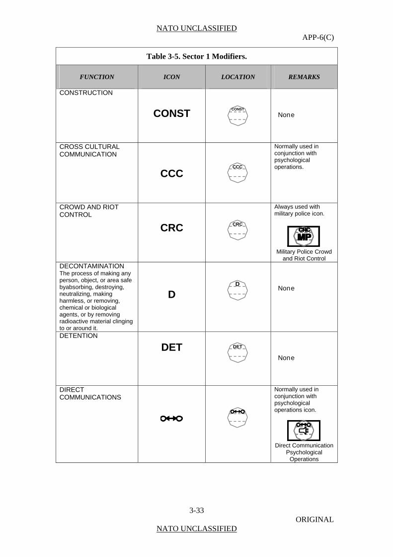
NATO UNCLASSIFIED APP-6(C)
3-33 ORIGINAL
NATO UNCLASSIFIED
Table 3-5. Sector 1 Modifiers.
FUNCTION ICON LOCATION REMARKS
CONSTRUCTION
CONST
CONST
None
CROSS CULTURAL COMMUNICATION
CCC
CCC
Normally used in conjunction with psychological operations.
CROWD AND RIOT CONTROL
CRC
CRC
Always used with military police icon.
Military Police Crowd
and Riot Control DECONTAMINATION The process of making any person, object, or area safe byabsorbing, destroying, neutralizing, making harmless, or removing, chemical or biological agents, or by removing radioactive material clinging to or around it.
D
D
None
DETENTION
DET
DET
None
DIRECT COMMUNICATIONS
Normally used in conjunction with psychological operations icon.
Direct Communication
Psychological Operations
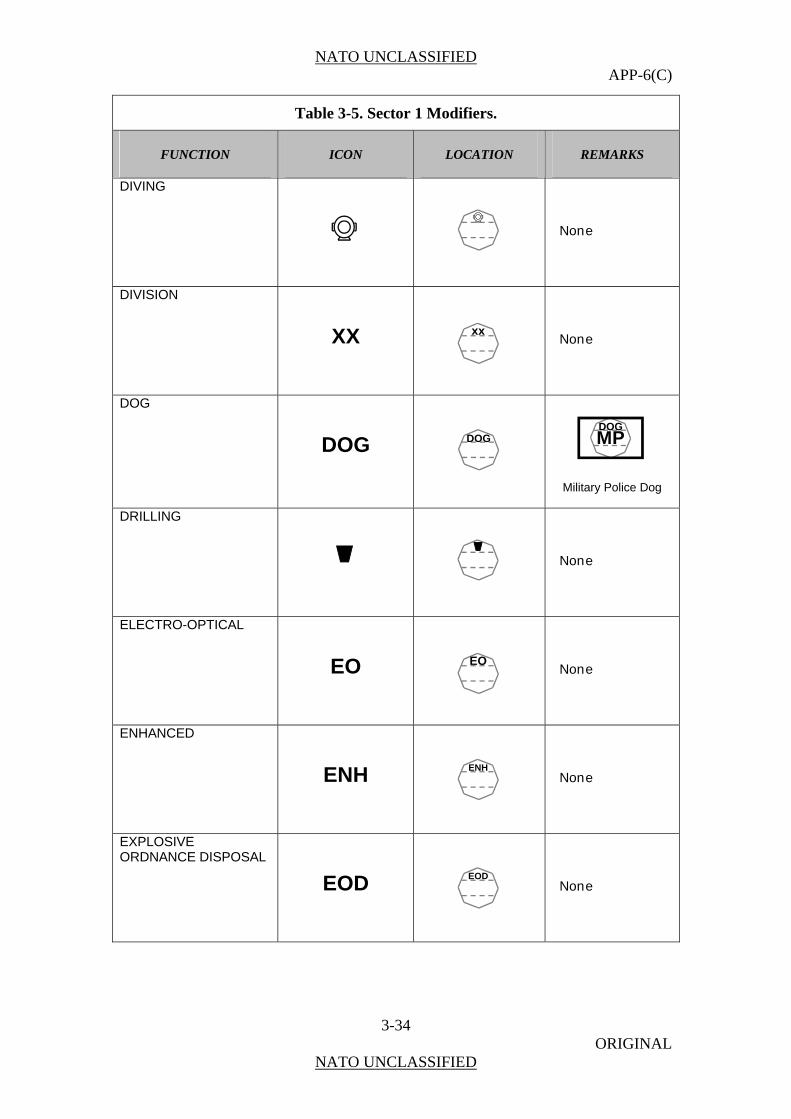
NATO UNCLASSIFIED APP-6(C)
3-34 ORIGINAL
NATO UNCLASSIFIED
Table 3-5. Sector 1 Modifiers.
FUNCTION ICON LOCATION REMARKS
DIVING
None
DIVISION
XX
xx
None
DOG
DOG
DOG
DOGMP
Military Police Dog
DRILLING
None
ELECTRO-OPTICAL
EO
EO
None
ENHANCED
ENH
ENH
None
EXPLOSIVE ORDNANCE DISPOSAL
EOD
EOD
None
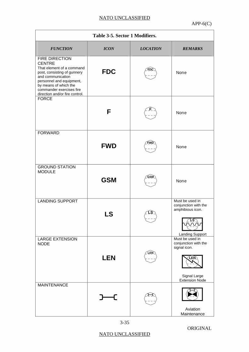
NATO UNCLASSIFIED APP-6(C)
3-35 ORIGINAL
NATO UNCLASSIFIED
Table 3-5. Sector 1 Modifiers.
FUNCTION ICON LOCATION REMARKS
FIRE DIRECTION CENTRE That element of a command post, consisting of gunnery and communication personnel and equipment, by means of which the commander exercises fire direction and/or fire control.
FDC
FDC
None
FORCE
F
F
None
FORWARD
FWD
FWD
None
GROUND STATION MODULE
GSM
GSM
None
LANDING SUPPORT
LS
LS
Must be used in conjunction with the amphibious icon.
LS
Landing Support
LARGE EXTENSION NODE
LEN
LEN
Must be used in conjunction with the signal icon.
LEN
Signal Large Extension Node
MAINTENANCE
Aviation Maintenance

NATO UNCLASSIFIED APP-6(C)
3-36 ORIGINAL
NATO UNCLASSIFIED
Table 3-5. Sector 1 Modifiers.
FUNCTION ICON LOCATION REMARKS
METEOROLOGICAL
MET
MET
METMET
Field Artillery Meteorological
MINE COUNTERMEASURE
MCM
MCM
None
MISSILE
Missile Maintenance
(MOBILE) ADVISOR AND SUPPORT
None
MOBILE SUBSCRIBER EQUIPMENT
MSE
MSE
Must be used in conjunction with the signal icon.
MSE
Signal Mobile
Subscriber Equipment MOBILITY SUPPORT
MS
MS
None
MOVEMENT CONTROL CENTRE An organization responsible for planning, routing, scheduling, and control of personnel and cargo movements over lines of communications.
MCC
MCC
None
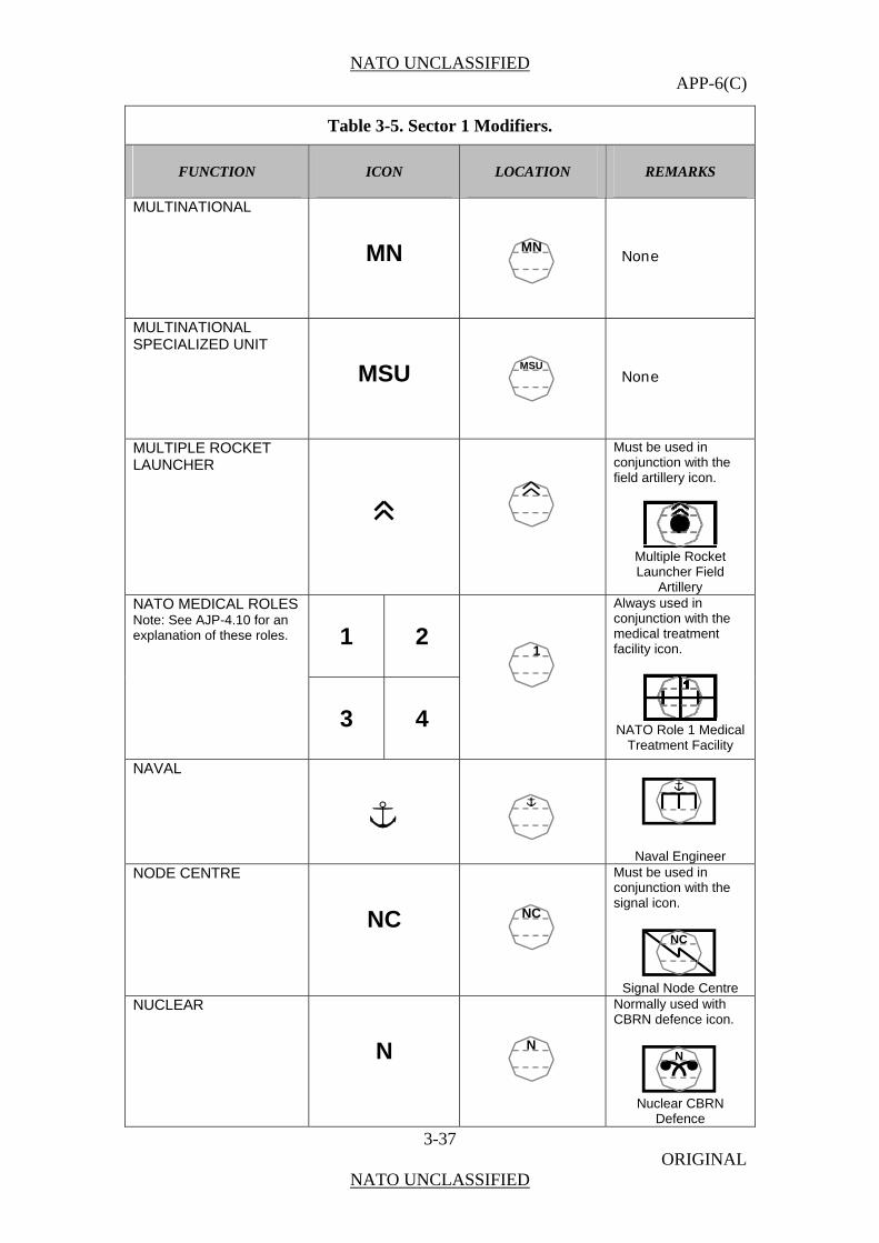
NATO UNCLASSIFIED APP-6(C)
3-37 ORIGINAL
NATO UNCLASSIFIED
Table 3-5. Sector 1 Modifiers.
FUNCTION ICON LOCATION REMARKS
MULTINATIONAL
MN
MN
None
MULTINATIONAL SPECIALIZED UNIT
MSU
MSU
None
MULTIPLE ROCKET LAUNCHER
Must be used in conjunction with the field artillery icon.
Multiple Rocket Launcher Field
Artillery
1
2
NATO MEDICAL ROLES Note: See AJP-4.10 for an explanation of these roles.
3
4
1
Always used in conjunction with the medical treatment facility icon.
NATO Role 1 Medical
Treatment Facility
NAVAL
Naval Engineer NODE CENTRE
NC
NC
Must be used in conjunction with the signal icon.
NC
Signal Node Centre
NUCLEAR
N
N
Normally used with CBRN defence icon.
N
Nuclear CBRN
Defence

NATO UNCLASSIFIED APP-6(C)
3-38 ORIGINAL
NATO UNCLASSIFIED
Table 3-5. Sector 1 Modifiers.
FUNCTION ICON LOCATION REMARKS
OPERATIONS
OPS
OPS
None
RADAR
Field Artillery Radar
RADIOLOGICAL
RAD
RAD
Normally used with CBRN Defence.
RAD
Radiological CBRN
Defence SEARCH AND RESCUE The use of aircraft, surface craft, submarines, specialized rescue teams and equipment to search for and rescue personnel in distress on land or at sea.
SAR
SAR
None
SECURITY
SEC
SEC
None
SENSOR
MIMI
Military Intelligence
Sensor
SENSOR CONTROL MODULE (SCM)
SCM
SCM
Normally used in conjunction with the military intelligence icon and sensor modifier.
SCMSCM
Military Intelligence
Sensor Control Module
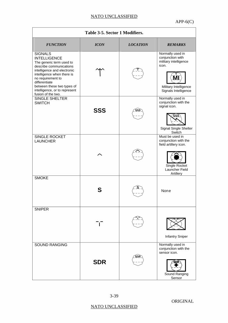
NATO UNCLASSIFIED APP-6(C)
3-39 ORIGINAL
NATO UNCLASSIFIED
Table 3-5. Sector 1 Modifiers.
FUNCTION ICON LOCATION REMARKS
SIGNALS INTELLIGENCE The generic term used to describe communications intelligence and electronic intelligence when there is no requirement to differentiate between these two types of intelligence, or to represent fusion of the two.
Normally used in conjunction with military intelligence icon.
MI
Military Intelligence Signals Intelligence
SINGLE SHELTER SWITCH
SSS
SSS
Normally used in conjunction with the signal icon.
SSS
Signal Single Shelter
Switch SINGLE ROCKET LAUNCHER
Must be used in conjunction with the field artillery icon.
Single Rocket Launcher Field
Artillery SMOKE
S
S
None
SNIPER
Infantry Sniper
SOUND RANGING
SDR
SDR
Normally used in conjunction with the sensor icon.
SDRSDRSDR
Sound Ranging
Sensor
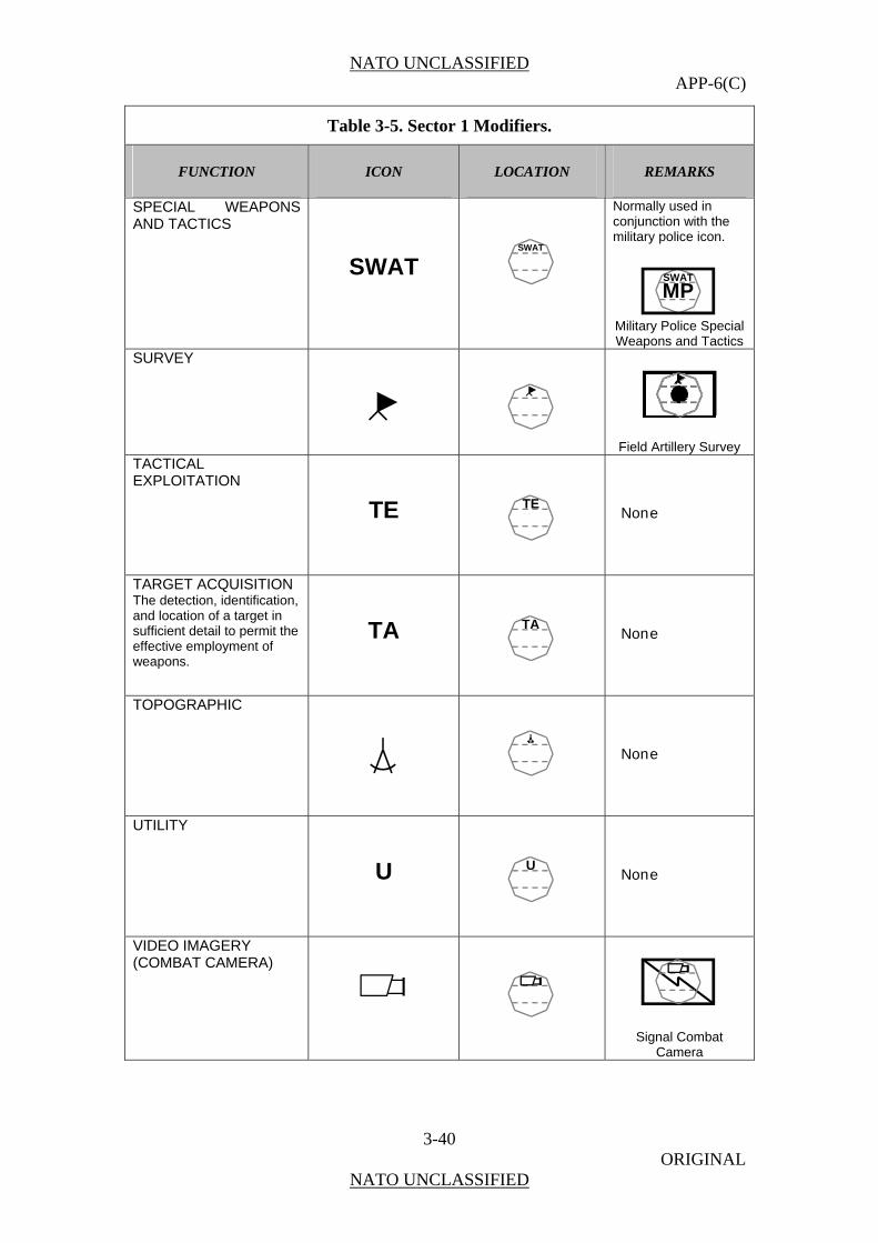
NATO UNCLASSIFIED APP-6(C)
3-40 ORIGINAL
NATO UNCLASSIFIED
Table 3-5. Sector 1 Modifiers.
FUNCTION ICON LOCATION REMARKS
SPECIAL WEAPONS AND TACTICS
SWAT
SWAT
Normally used in conjunction with the military police icon.
SWAT
MP
Military Police Special Weapons and Tactics
SURVEY
Field Artillery Survey
TACTICAL EXPLOITATION
TE
TE
None
TARGET ACQUISITION The detection, identification, and location of a target in sufficient detail to permit the effective employment of weapons.
TA
TA
None
TOPOGRAPHIC
None
UTILITY
U
U
None
VIDEO IMAGERY (COMBAT CAMERA)
Signal Combat Camera
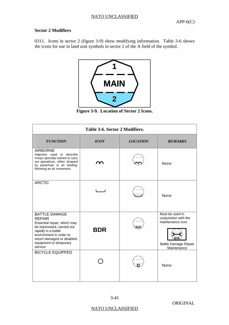
NATO UNCLASSIFIED APP-6(C)
3-41 ORIGINAL
NATO UNCLASSIFIED
Sector 2 Modifiers 0311. Icons in sector 2 (figure 3-9) show modifying information. Table 3-6 shows the icons for use in land unit symbols in sector 2 of the A field of the symbol.
MAIN
1
2
MAIN
1
2
Figure 3-9. Location of Sector 2 Icons.
Table 3-6. Sector 2 Modifiers.
FUNCTION ICON LOCATION REMARKS
AIRBORNE Adjective used to describe troops specially trained to carry out operations, either dropped by parachute or air landing, following an air movement.
None
ARCTIC
None
BATTLE DAMAGE REPAIR Essential repair, which may be improvised, carried out rapidly in a battle environment in order to return damaged or disabled equipment to temporary service.
BDR
BDR
Must be used in conjunction with the maintenance icon.
BDR
Battle Damage Repair Maintenance
BICYCLE EQUIPPED
None

NATO UNCLASSIFIED APP-6(C)
3-42 ORIGINAL
NATO UNCLASSIFIED
Table 3-6. Sector 2 Modifiers.
FUNCTION ICON LOCATION REMARKS
CASUALTY STAGING CS
CS
Always used in conjunction with the medical icon and is offset to the right of the centre line.
CSCS
Medical Casualty Staging Unit
CLEARING
CLR
CLR
Normally used in conjunction with the mine icon.
CLRCLR
Mine Clearing CLOSE RANGE
CR
CR
Normally used in conjunction with UAV icon.
CRCR
Close Range Unattended Aerial
Vehicle CONTROL
Normally used in conjunction with the unmanned systems icon.
UAV Control
DECONTAMINATION
D
D
Used as a sector 2 modifier when C, B, R, or N is used as a sector 1 modifier.
D
C
Chemical
Decontamination DEMOLITION.
DEM
DEM
Normally used in conjunction with the Engineer icon
DEMDEM
Engineer Demolition
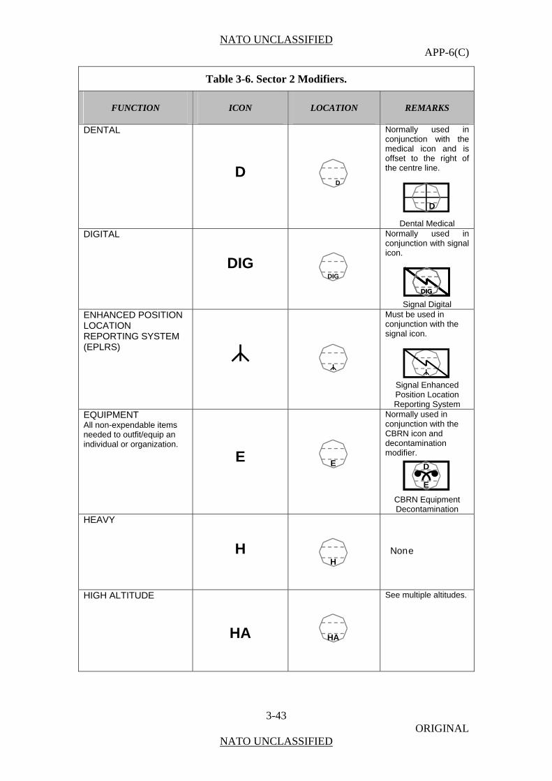
NATO UNCLASSIFIED APP-6(C)
3-43 ORIGINAL
NATO UNCLASSIFIED
Table 3-6. Sector 2 Modifiers.
FUNCTION ICON LOCATION REMARKS
DENTAL
D
D
Normally used in conjunction with the medical icon and is offset to the right of the centre line.
D
Dental Medical DIGITAL
DIG
DIG
Normally used in conjunction with signal icon.
DIGDIG
Signal Digital ENHANCED POSITION LOCATION REPORTING SYSTEM (EPLRS)
Must be used in conjunction with the signal icon.
Signal Enhanced Position Location Reporting System
EQUIPMENT All non-expendable items needed to outfit/equip an individual or organization.
E
E
Normally used in conjunction with the CBRN icon and decontamination modifier.
D
E
CBRN Equipment Decontamination
HEAVY
H
H
None
HIGH ALTITUDE
HA
HA
See multiple altitudes.

NATO UNCLASSIFIED APP-6(C)
3-44 ORIGINAL
NATO UNCLASSIFIED
Table 3-6. Sector 2 Modifiers.
FUNCTION ICON LOCATION REMARKS
INTERMODAL
Normally used in conjunction with transportation icon.
Intermodal
Transportation INTENSIVE CARE
IC
IC
Normally used in conjunction with the medical icon and is offset to the right of the centre line.
ICIC
Medical Intensive Care
LIGHT
L
L
None
LABORATORY
LAB
LAB
None
LAUNCHER
Normally used in conjunction with the unmanned systems icon.
UAV Launcher LONG RANGE
LR
LR
None

NATO UNCLASSIFIED APP-6(C)
3-45 ORIGINAL
NATO UNCLASSIFIED
Table 3-6. Sector 2 Modifiers.
FUNCTION ICON LOCATION REMARKS
LOW ALTITUDE
LA
LA
See multiple altitudes.
MEDIUM
M
M
None
MEDIUM ALTITUDE
MA
MA
See multiple altitudes.
MEDIUM RANGE
MR
MR
None
MOUNTAIN
Base must touch or be near the bottom of the frame (see below).
MULTIPLE ALTITUDES
H/MA
H/MA
The Multiple Altitudes icon uses the combination of altitudes icons. Note: This example represents high to medium altitude.

NATO UNCLASSIFIED APP-6(C)
3-46 ORIGINAL
NATO UNCLASSIFIED
Table 3-6. Sector 2 Modifiers.
FUNCTION ICON LOCATION REMARKS
MULTI-CHANNEL
MC
MC
Normally used in conjunction with signal icon.
MCMCMC
Signal Multi-channel
OPTICAL (FLASH)
OPT
OPT
Normally used in conjunction with the
field artillery icon and target acquisition
modifier.
TA
OPT
Field Artillery Optical (Flash) Target
Acquisition PACK ANIMAL
None
PATIENT EVACUATION COORDINATION
PEC
PEC
Normally used in conjunction with the medical icon and is offset to the right of the centre line.
PECPEC
Medical Patient Evacuation
Coordination PREVENTIVE MAINTENANCE
PM
PM
Must be used in conjunction with the maintenance icon.
PM
Preventive Maintenance
PSYCHOLOGICAL
P
P
Normally used in conjunction with the medical icon and is offset to the right of the centre line.
P
Psychological Medical

NATO UNCLASSIFIED APP-6(C)
3-47 ORIGINAL
NATO UNCLASSIFIED
Table 3-6. Sector 2 Modifiers.
FUNCTION ICON LOCATION REMARKS
RADIO RELAY LINE OF SIGHT
Normally used in conjunction with signal icon.
Signal Line of Sight
Radio Relay RAILROAD
None
RECOVERY (UNMANNED SYSTEMS) In air operations, that phase of a mission which involves the return of an aircraft to a base.
Normally used in conjunction with the unmanned systems icon.
UAV Recovery
RECOVERY (MAINTENANCE) In battlefield maintenance, the extrication of an abandoned, disabled or immobilized vehicle and, if necessary, its removal to a maintenance point.
None
RESCUE COORDINATION CENTRE.
RCC
RCC
Normally used in conjunction with the medical icon and is offset to the right of the centre line.
RCCRCC
Medical Rescue Coordination Centre
RIVERINE
None
SINGLE CHANNEL
SC
SC
Normally used in conjunction with signal
icon.
SCSC
Single Channel
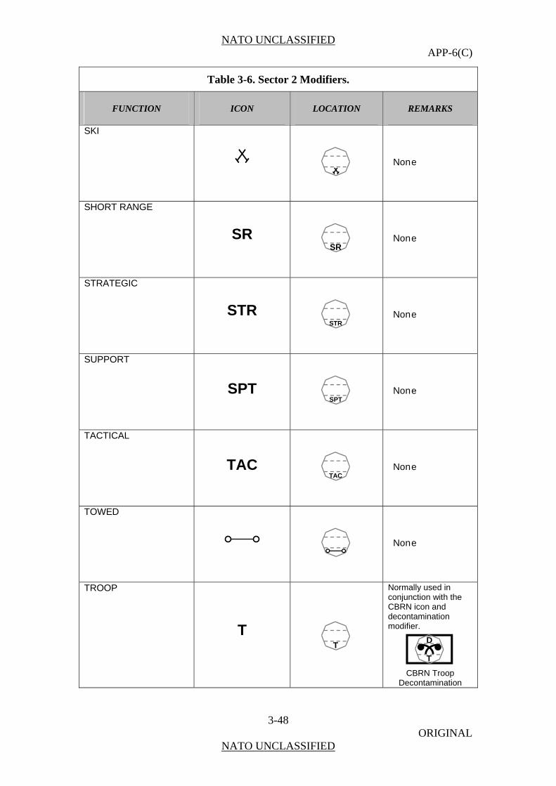
NATO UNCLASSIFIED APP-6(C)
3-48 ORIGINAL
NATO UNCLASSIFIED
Table 3-6. Sector 2 Modifiers.
FUNCTION ICON LOCATION REMARKS
SKI
None
SHORT RANGE
SR
SR
None
STRATEGIC
STR
STR
None
SUPPORT
SPT
SPT
None
TACTICAL
TAC
TAC
None
TOWED
None
TROOP
T
T
Normally used in conjunction with the CBRN icon and decontamination modifier.
D
T
CBRN Troop Decontamination

NATO UNCLASSIFIED APP-6(C)
3-49 ORIGINAL
NATO UNCLASSIFIED
Table 3-6. Sector 2 Modifiers.
FUNCTION ICON LOCATION REMARKS
VERTICAL OR SHORT TAKE-OFF AND LANDING (VSTOL)
VSTOL
VSTOL
Normally used in conjunction with fixed wing aviation or rotary wing aviation.
VSTOL
Rotary Wing Aviation Vertical Short Takeoff
and Landing VETERINARY
V
V
Normally used in conjunction with the medical icon and is offset to the right of the centre line.
V
Veterinary Medical WHEELED
None
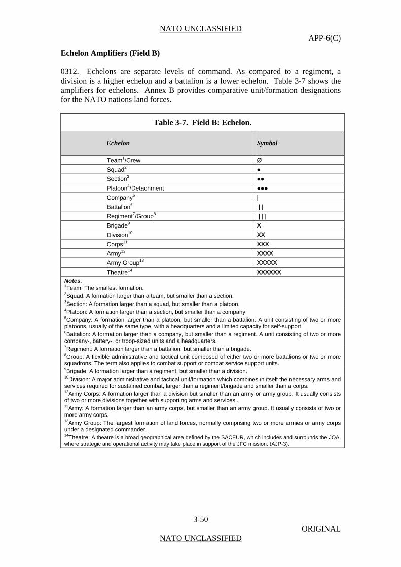
NATO UNCLASSIFIED APP-6(C)
3-50 ORIGINAL
NATO UNCLASSIFIED
Echelon Amplifiers (Field B) 0312. Echelons are separate levels of command. As compared to a regiment, a division is a higher echelon and a battalion is a lower echelon. Table 3-7 shows the amplifiers for echelons. Annex B provides comparative unit/formation designations for the NATO nations land forces.
Table 3-7. Field B: Echelon.
Echelon Symbol
Team1/Crew Ø
Squad2 ●
Section3 ●●
Platoon4/Detachment ●●●
Company5 |
Battalion6 | |
Regiment7/Group8 | | |
Brigade9 X
Division10 XX
Corps11 XXX
Army12 XXXX
Army Group13 XXXXX
Theatre14 XXXXXX Notes: 1Team: The smallest formation. 2Squad: A formation larger than a team, but smaller than a section. 3Section: A formation larger than a squad, but smaller than a platoon. 4Platoon: A formation larger than a section, but smaller than a company. 5Company: A formation larger than a platoon, but smaller than a battalion. A unit consisting of two or more platoons, usually of the same type, with a headquarters and a limited capacity for self-support. 6Battalion: A formation larger than a company, but smaller than a regiment. A unit consisting of two or more company-, battery-, or troop-sized units and a headquarters. 7Regiment: A formation larger than a battalion, but smaller than a brigade. 8Group: A flexible administrative and tactical unit composed of either two or more battalions or two or more squadrons. The term also applies to combat support or combat service support units. 9Brigade: A formation larger than a regiment, but smaller than a division. 10Division: A major administrative and tactical unit/formation which combines in itself the necessary arms and services required for sustained combat, larger than a regiment/brigade and smaller than a corps. 12Army Corps: A formation larger than a division but smaller than an army or army group. It usually consists of two or more divisions together with supporting arms and services.. 12Army: A formation larger than an army corps, but smaller than an army group. It usually consists of two or more army corps. 13Army Group: The largest formation of land forces, normally comprising two or more armies or army corps under a designated commander. 14Theatre: A theatre is a broad geographical area defined by the SACEUR, which includes and surrounds the JOA, where strategic and operational activity may take place in support of the JFC mission. (AJP-3).
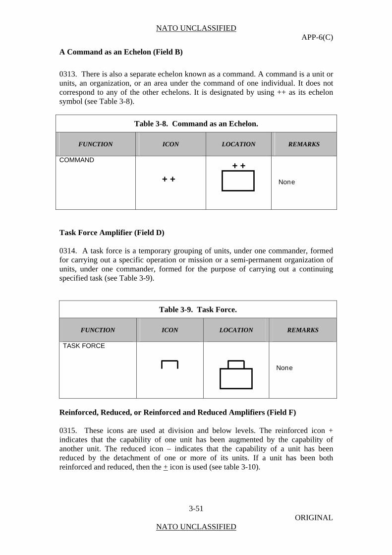
NATO UNCLASSIFIED APP-6(C)
3-51 ORIGINAL
NATO UNCLASSIFIED
A Command as an Echelon (Field B)
0313. There is also a separate echelon known as a command. A command is a unit or units, an organization, or an area under the command of one individual. It does not correspond to any of the other echelons. It is designated by using ++ as its echelon symbol (see Table 3-8).
Table 3-8. Command as an Echelon.
FUNCTION ICON LOCATION REMARKS
COMMAND
None
Task Force Amplifier (Field D) 0314. A task force is a temporary grouping of units, under one commander, formed for carrying out a specific operation or mission or a semi-permanent organization of units, under one commander, formed for the purpose of carrying out a continuing specified task (see Table 3-9).
Table 3-9. Task Force.
FUNCTION ICON LOCATION REMARKS
TASK FORCE
None
Reinforced, Reduced, or Reinforced and Reduced Amplifiers (Field F) 0315. These icons are used at division and below levels. The reinforced icon + indicates that the capability of one unit has been augmented by the capability of another unit. The reduced icon – indicates that the capability of a unit has been reduced by the detachment of one or more of its units. If a unit has been both reinforced and reduced, then the + icon is used (see table 3-10).
+ +
+ +
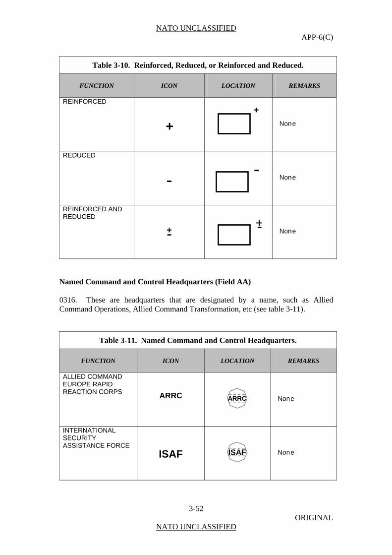
NATO UNCLASSIFIED APP-6(C)
3-52 ORIGINAL
NATO UNCLASSIFIED
Table 3-10. Reinforced, Reduced, or Reinforced and Reduced.
FUNCTION ICON LOCATION REMARKS
REINFORCED
None
REDUCED
None
REINFORCED AND REDUCED
None
Named Command and Control Headquarters (Field AA) 0316. These are headquarters that are designated by a name, such as Allied Command Operations, Allied Command Transformation, etc (see table 3-11).
Table 3-11. Named Command and Control Headquarters.
FUNCTION ICON LOCATION REMARKS
ALLIED COMMAND EUROPE RAPID REACTION CORPS
ARRC
ARRC
None
INTERNATIONAL SECURITY ASSISTANCE FORCE
ISAF
ISAF
None
--
+-
++
-+
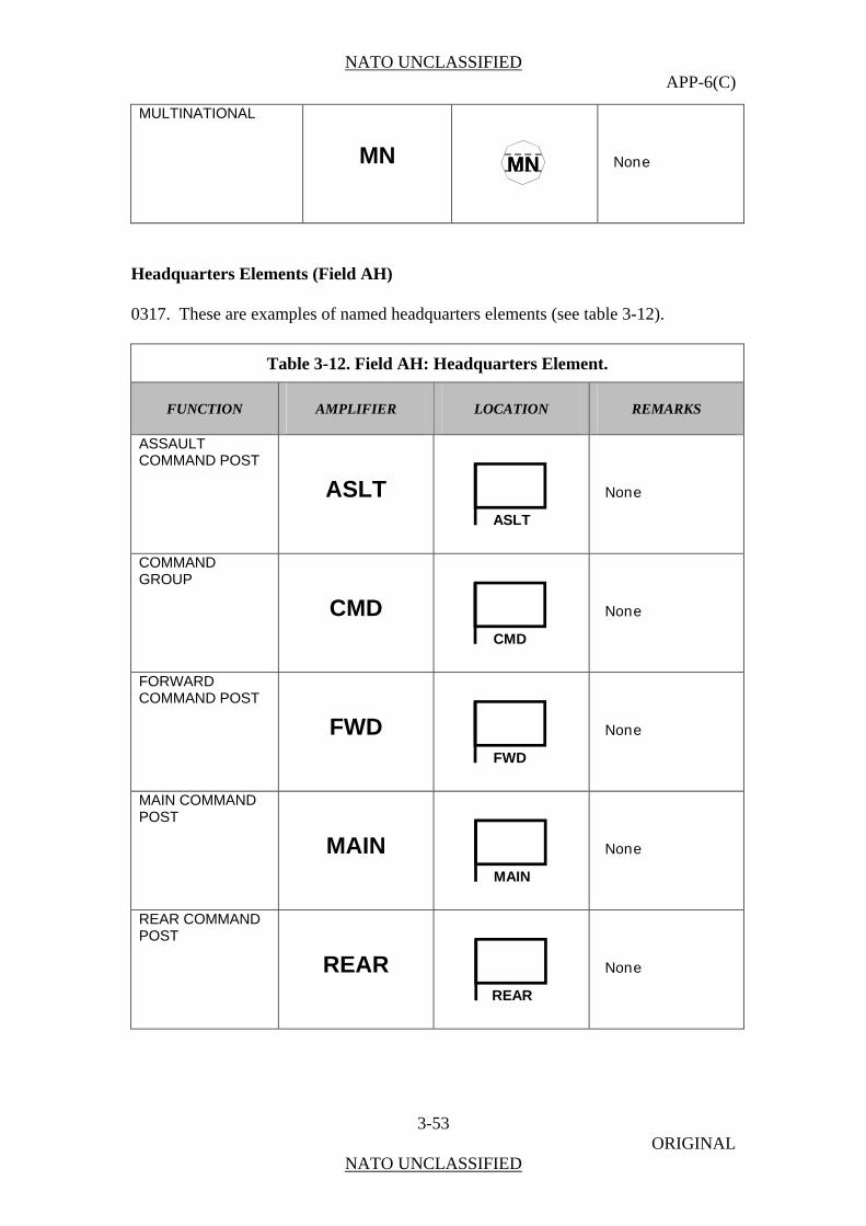
NATO UNCLASSIFIED APP-6(C)
3-53 ORIGINAL
NATO UNCLASSIFIED
MULTINATIONAL
MN
MNMN
None
Headquarters Elements (Field AH) 0317. These are examples of named headquarters elements (see table 3-12).
Table 3-12. Field AH: Headquarters Element.
FUNCTION AMPLIFIER LOCATION REMARKS
ASSAULT COMMAND POST
ASLT
ASLT
None
COMMAND GROUP
CMD
CMD
None
FORWARD COMMAND POST
FWD
FWD
None
MAIN COMMAND POST
MAIN
MAIN
None
REAR COMMAND POST
REAR
REAR
None
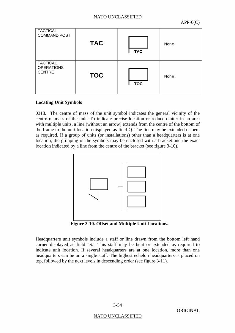
NATO UNCLASSIFIED APP-6(C)
3-54 ORIGINAL
NATO UNCLASSIFIED
TACTICAL COMMAND POST
TAC
TAC
None
TACTICAL OPERATIONS CENTRE
TOC
TOC
None
Locating Unit Symbols 0318. The centre of mass of the unit symbol indicates the general vicinity of the centre of mass of the unit. To indicate precise location or reduce clutter in an area with multiple units, a line (without an arrow) extends from the centre of the bottom of the frame to the unit location displayed as field Q. The line may be extended or bent as required. If a group of units (or installations) other than a headquarters is at one location, the grouping of the symbols may be enclosed with a bracket and the exact location indicated by a line from the centre of the bracket (see figure 3-10).
Figure 3-10. Offset and Multiple Unit Locations.
Headquarters unit symbols include a staff or line drawn from the bottom left hand corner displayed as field "S.” This staff may be bent or extended as required to indicate unit location. If several headquarters are at one location, more than one headquarters can be on a single staff. The highest echelon headquarters is placed on top, followed by the next levels in descending order (see figure 3-11).

NATO UNCLASSIFIED APP-6(C)
3-55 ORIGINAL
NATO UNCLASSIFIED
Figure 3-11. Offset Headquarters and Multiple Headquarters Locations.
Individual and Organization Main Sector Icons 0319. These icons represent non-military individuals and organizations. Icons in the main sector (figure 3-6 on page 3-9) normally reflect the main function of the symbol, but in some cases can also reflect modifying information as well. Table 3-13 below shows the icons for use in land individual and organization symbols in the main sector of the A field of the symbol. In most cases, the dimensions of the icon will be sized to occupy as much area in the main sector as is available. However, in some cases the icon may be reduced to allow more room for modifiers for better recognition or to allow for one icon to modify another.
Table 3-13. Main Sector Icons.
FUNCTION ICON LOCATION REMARKS
CIVILIAN POLICE
None
ENVIRONMENTAL PROTECTION
None
GOVERNMENT ORGANIZATION
GO
GO
None

NATO UNCLASSIFIED APP-6(C)
3-56 ORIGINAL
NATO UNCLASSIFIED
Table 3-13. Main Sector Icons.
FUNCTION ICON LOCATION REMARKS
INTERNAL SECURITY FORCE
ISF
ISF
None
INDIVIDUAL
None
ORGANIZATION OR GROUP
None
KILLING VICTIM
None
KILLING VICTIMS
None
VICTIM OF AN ATTEMPTED CRIME
None
SPY
SPY
SPY
None
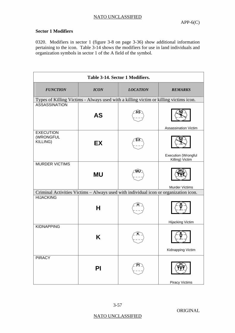
NATO UNCLASSIFIED APP-6(C)
3-57 ORIGINAL
NATO UNCLASSIFIED
Sector 1 Modifiers 0320. Modifiers in sector 1 (figure 3-8 on page 3-36) show additional information pertaining to the icon. Table 3-14 shows the modifiers for use in land individuals and organization symbols in sector 1 of the A field of the symbol.
Table 3-14. Sector 1 Modifiers.
FUNCTION ICON LOCATION REMARKS
Types of Killing Victims - Always used with a killing victim or killing victims icon. ASSASSINATION
AS
AS
ASAS
Assassination Victim EXECUTION (WRONGFUL KILLING)
EX
EX
EXEX
Execution (Wrongful Killing) Victim
MURDER VICTIMS MU
MU
MUMU
Murder Victims Criminal Activities Victims – Always used with individual icon or organization icon. HIJACKING
H
H
HHH
Hijacking Victim KIDNAPPING
K
K
KKK
Kidnapping Victim
PIRACY PI
PI
PIPI
Piracy Victims
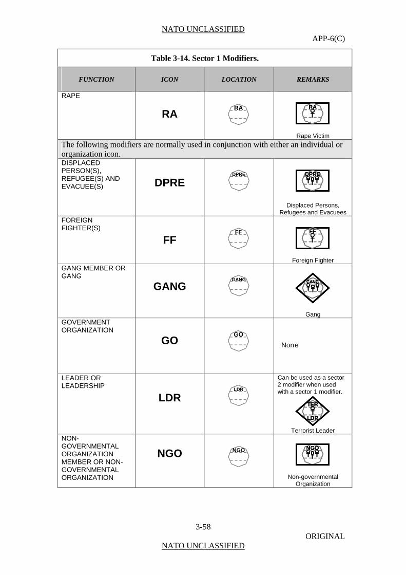
NATO UNCLASSIFIED APP-6(C)
3-58 ORIGINAL
NATO UNCLASSIFIED
Table 3-14. Sector 1 Modifiers.
FUNCTION ICON LOCATION REMARKS
RAPE RA
RA
RARA
Rape Victim The following modifiers are normally used in conjunction with either an individual or organization icon. DISPLACED PERSON(S), REFUGEE(S) AND EVACUEE(S)
DPRE
DPRE
DPREDPRE
Displaced Persons, Refugees and Evacuees
FOREIGN FIGHTER(S)
FF
FF
FFFF
Foreign Fighter GANG MEMBER OR GANG
GANG
GANG
GANGGANGGANG
Gang GOVERNMENT ORGANIZATION
GO
GO
None
LEADER OR LEADERSHIP
LDR
LDR
Can be used as a sector 2 modifier when used with a sector 1 modifier.
TER
LDR
TER
LDR
TER
LDR
Terrorist Leader NON-GOVERNMENTAL ORGANIZATION MEMBER OR NON-GOVERNMENTAL ORGANIZATION
NGO
NGO
NGONGONGO
Non-governmental Organization
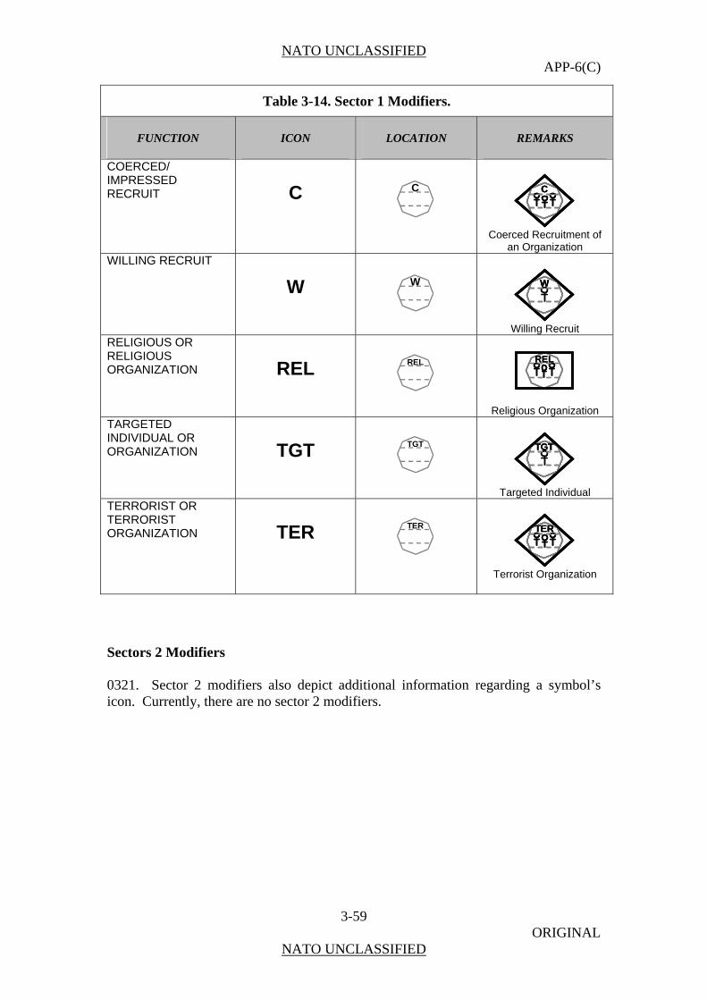
NATO UNCLASSIFIED APP-6(C)
3-59 ORIGINAL
NATO UNCLASSIFIED
Table 3-14. Sector 1 Modifiers.
FUNCTION ICON LOCATION REMARKS
COERCED/ IMPRESSED RECRUIT
C
C
CCC
Coerced Recruitment of
an Organization WILLING RECRUIT
W
W
WWW
Willing Recruit
RELIGIOUS OR RELIGIOUS ORGANIZATION
REL
REL
RELREL
Religious Organization TARGETED INDIVIDUAL OR ORGANIZATION
TGT
TGT
TGTTGTTGT
Targeted Individual
TERRORIST OR TERRORIST ORGANIZATION
TER
TER
TERTERTER
Terrorist Organization
Sectors 2 Modifiers 0321. Sector 2 modifiers also depict additional information regarding a symbol’s icon. Currently, there are no sector 2 modifiers.

NATO UNCLASSIFIED APP-6(C)
3-60 ORIGINAL
NATO UNCLASSIFIED
SECTION III
LAND EQUIPMENT SYMBOLS
General
0322. This section establishes a single standard for developing land equipment symbols. Equipment is all non-expendable items that are needed to outfit or equip an individual or organization. This section provides a wide selection of land equipment icons with a standard method for constructing land equipment symbols. Once the user is familiar with the prescribed system, any land equipment symbol can be developed using the logical sequence provided in this chapter. The symbols shown in this chapter are adequate for depicting hostile units. Avoid using any symbol that differs from those in this publication. If, after searching doctrinal icons, it is necessary to create a new symbol, explain the symbol in an accompanying legend. Computer-generated systems may have difficulty in passing non-standard symbols.
Composition of Equipment Symbols
0323. A land equipment symbol is normally composed of a frame which is optional, colour (fill), equipment icon, modifier, and text or graphic amplifiers (see figure 3-12). (See table 3-15 for the steps used to build equipment symbols.) Icons and modifiers for equipment are displayed differently for weapons systems and vehicles. Most of the icons fill the entire frame and their size modifier is part of the icon, normally located in the main sector. The mobility is shown outside the frame as a graphic amplifier. However, there are also icons that follow the normal pattern established in chapter 1. A non-standard symbol is used for the building section to show a similar pattern for development while showing the variation of this legacy system.
Figure 3-12. Land Equipment Symbol Composition.
Frame
Color
Icon
Text Amplifier
Graphic Amplifier
M - 198Modifier
Frame
Colour
Icon
Text Amplifier
Graphic Amplifier
M - 198Modifier
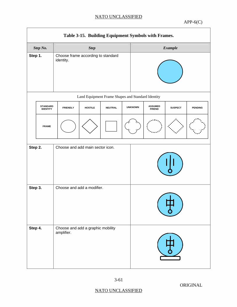
NATO UNCLASSIFIED APP-6(C)
3-61 ORIGINAL
NATO UNCLASSIFIED
Table 3-15. Building Equipment Symbols with Frames.
Step No. Step Example
Step 1. Choose frame according to standard identity.
Land Equipment Frame Shapes and Standard Identity
Step 2. Choose and add main sector icon.
Step 3. Choose and add a modifier.
Step 4. Choose and add a graphic mobility amplifier.
STANDARD IDENTITY
FRAME
PENDINGFRIENDLY HOSTILE NEUTRAL UNKNOWN ASSUMEDFRIEND SUSPECT
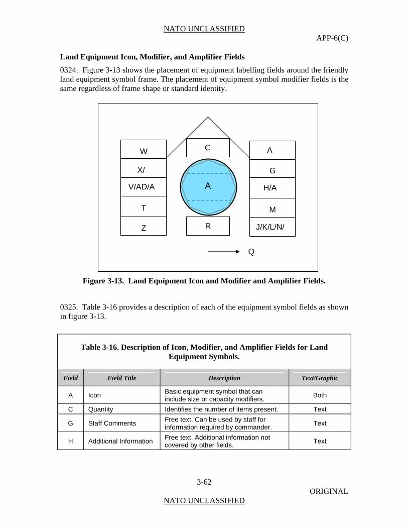
NATO UNCLASSIFIED APP-6(C)
3-62 ORIGINAL
NATO UNCLASSIFIED
Land Equipment Icon, Modifier, and Amplifier Fields
0324. Figure 3-13 shows the placement of equipment labelling fields around the friendly land equipment symbol frame. The placement of equipment symbol modifier fields is the same regardless of frame shape or standard identity.
Figure 3-13. Land Equipment Icon and Modifier and Amplifier Fields.
0325. Table 3-16 provides a description of each of the equipment symbol fields as shown in figure 3-13.
Table 3-16. Description of Icon, Modifier, and Amplifier Fields for Land Equipment Symbols.
Field Field Title Description Text/Graphic
A Icon Basic equipment symbol that can include size or capacity modifiers.
Both
C Quantity Identifies the number of items present. Text
G Staff Comments Free text. Can be used by staff for information required by commander.
Text
H Additional Information Free text. Additional information not covered by other fields.
Text
W
X/
V/AD/A
T
Z
A
G
H/A
M
J/K/L/N/
C
Q
A
R
A
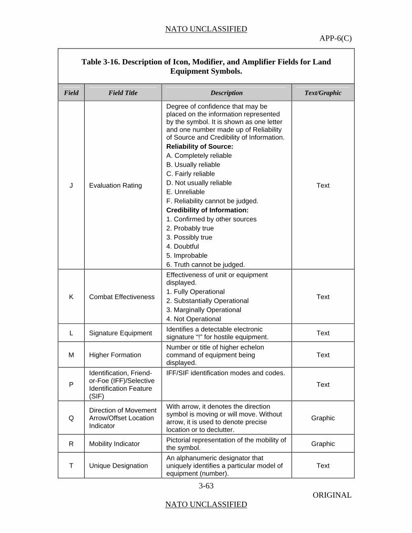
NATO UNCLASSIFIED APP-6(C)
3-63 ORIGINAL
NATO UNCLASSIFIED
Table 3-16. Description of Icon, Modifier, and Amplifier Fields for Land Equipment Symbols.
Field Field Title Description Text/Graphic
J Evaluation Rating
Degree of confidence that may be placed on the information represented by the symbol. It is shown as one letter and one number made up of Reliability of Source and Credibility of Information. Reliability of Source: A. Completely reliable B. Usually reliable C. Fairly reliable D. Not usually reliable E. Unreliable F. Reliability cannot be judged. Credibility of Information: 1. Confirmed by other sources 2. Probably true 3. Possibly true 4. Doubtful 5. Improbable 6. Truth cannot be judged.
Text
K Combat Effectiveness
Effectiveness of unit or equipment displayed. 1. Fully Operational 2. Substantially Operational 3. Marginally Operational 4. Not Operational
Text
L Signature Equipment Identifies a detectable electronic signature “!” for hostile equipment.
Text
M Higher Formation Number or title of higher echelon command of equipment being displayed.
Text
P
Identification, Friend-or-Foe (IFF)/Selective Identification Feature (SIF)
IFF/SIF identification modes and codes.
Text
Q Direction of Movement Arrow/Offset Location Indicator
With arrow, it denotes the direction symbol is moving or will move. Without arrow, it is used to denote precise location or to declutter.
Graphic
R Mobility Indicator Pictorial representation of the mobility of the symbol.
Graphic
T Unique Designation An alphanumeric designator that uniquely identifies a particular model of equipment (number).
Text
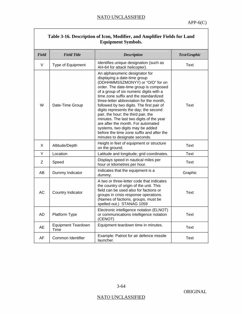
NATO UNCLASSIFIED APP-6(C)
3-64 ORIGINAL
NATO UNCLASSIFIED
Table 3-16. Description of Icon, Modifier, and Amplifier Fields for Land Equipment Symbols.
Field Field Title Description Text/Graphic
V Type of Equipment Identifies unique designation (such as AH-64 for attack helicopter).
Text
W Date-Time Group
An alphanumeric designator for displaying a date-time group (DDHHMMSSZMONYY) or “O/O” for on order. The date-time group is composed of a group of six numeric digits with a time zone suffix and the standardized three-letter abbreviation for the month, followed by two digits. The first pair of digits represents the day; the second pair, the hour; the third pair, the minutes. The last two digits of the year are after the month. For automated systems, two digits may be added before the time zone suffix and after the minutes to designate seconds.
Text
X Altitude/Depth Height in feet of equipment or structure on the ground.
Text
Y Location Latitude and longitude; grid coordinates. Text
Z Speed Displays speed in nautical miles per hour or kilometres per hour.
Text
AB Dummy Indicator Indicates that the equipment is a dummy.
Graphic
AC Country Indicator
A two or three-letter code that indicates the country of origin of the unit. This field can be used also for factions or groups in crisis response operations. (Names of factions, groups, must be spelled out.) STANAG 1059
Text
AD Platform Type Electronic intelligence notation (ELNOT) or communications intelligence notation (CENOT)
Text
AE Equipment Teardown Time
Equipment teardown time in minutes. Text
AF Common Identifier Example: Patriot for air defence missile launcher.
Text
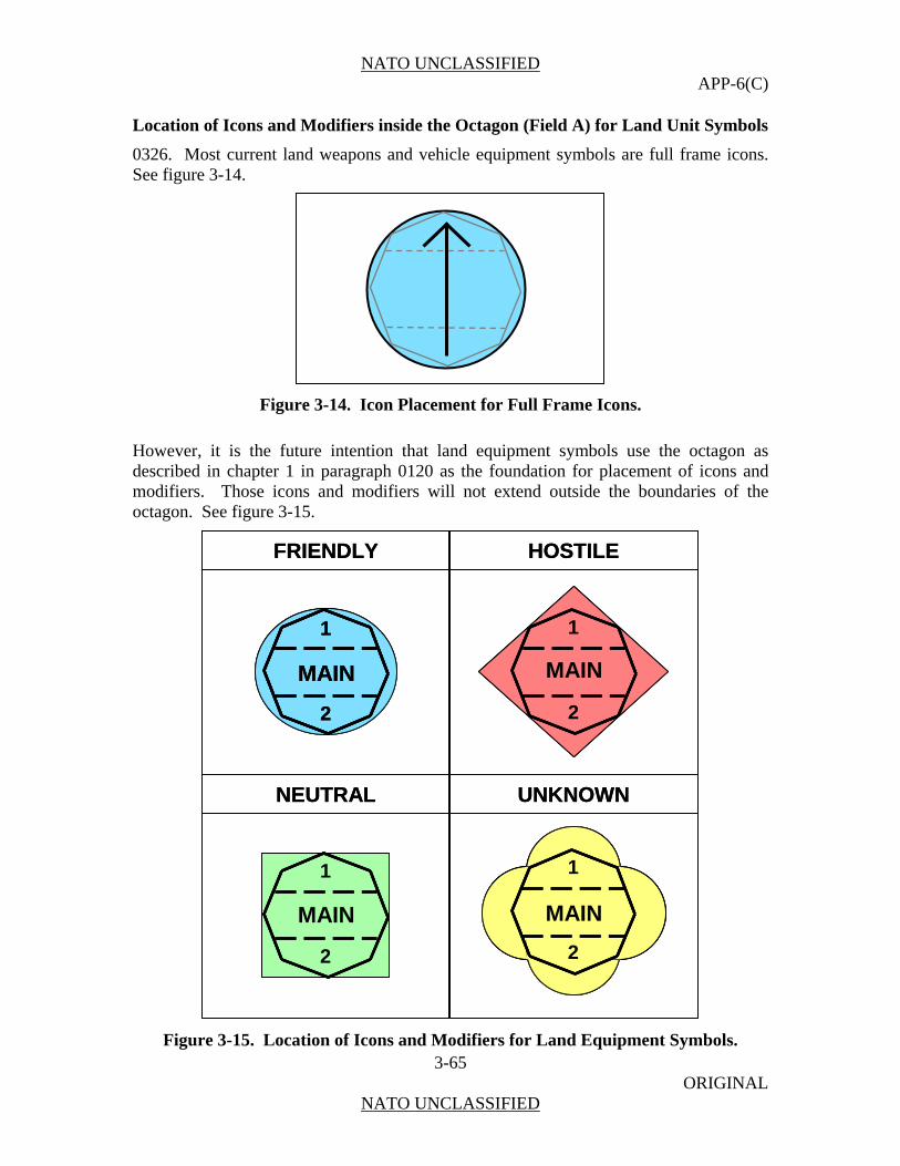
NATO UNCLASSIFIED APP-6(C)
3-65 ORIGINAL
NATO UNCLASSIFIED
Location of Icons and Modifiers inside the Octagon (Field A) for Land Unit Symbols
0326. Most current land weapons and vehicle equipment symbols are full frame icons. See figure 3-14.
MAIN
1
2
MAIN
1
2
MAIN
1
2
MAIN
1
2
Figure 3-14. Icon Placement for Full Frame Icons.
However, it is the future intention that land equipment symbols use the octagon as described in chapter 1 in paragraph 0120 as the foundation for placement of icons and modifiers. Those icons and modifiers will not extend outside the boundaries of the octagon. See figure 3-15.
FRIENDLY HOSTILE
NEUTRAL UNKNOWN
MAIN
1
2
MAIN
1
2
MAIN
1
2
MAIN
1
2
FRIENDLY HOSTILE
NEUTRAL UNKNOWN
MAIN
1
2
MAIN
1
2
MAIN
1
2
MAIN
1
2
MAIN
1
2
MAIN
1
2
MAIN
1
2
MAIN
1
2
MAIN
1
2
MAIN
1
2
Figure 3-15. Location of Icons and Modifiers for Land Equipment Symbols.
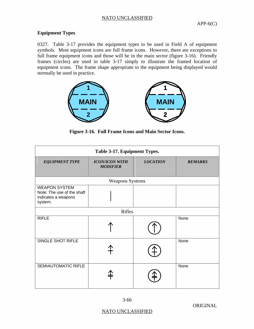
NATO UNCLASSIFIED APP-6(C)
3-66 ORIGINAL
NATO UNCLASSIFIED
Equipment Types 0327. Table 3-17 provides the equipment types to be used in Field A of equipment symbols. Most equipment icons are full frame icons. However, there are exceptions to full frame equipment icons and those will be in the main sector (figure 3-16). Friendly frames (circles) are used in table 3-17 simply to illustrate the framed location of equipment icons. The frame shape appropriate to the equipment being displayed would normally be used in practice.
MAIN
1
2
MAIN
1
2
MAIN
1
2
MAIN
1
2
MAIN
1
2
MAIN
1
2
MAIN
1
2
Figure 3-16. Full Frame Icons and Main Sector Icons.
Table 3-17. Equipment Types.
EQUIPMENT TYPE ICON/ICON WITH MODIFIER
LOCATION
REMARKS
Weapons Systems
WEAPON SYSTEM Note: The use of the shaft indicates a weapons system.
Rifles RIFLE
None
SINGLE SHOT RIFLE
None
SEMIAUTOMATIC RIFLE
None
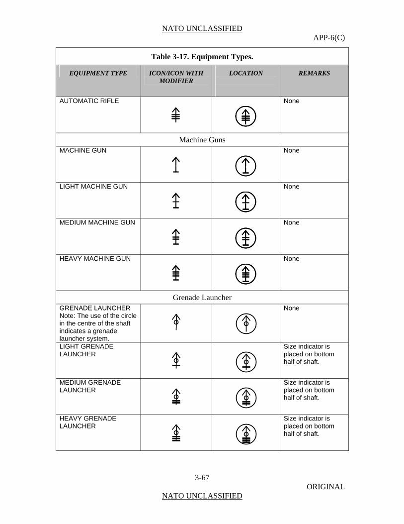
NATO UNCLASSIFIED APP-6(C)
3-67 ORIGINAL
NATO UNCLASSIFIED
Table 3-17. Equipment Types.
EQUIPMENT TYPE ICON/ICON WITH MODIFIER
LOCATION
REMARKS
AUTOMATIC RIFLE
None
Machine Guns MACHINE GUN
None
LIGHT MACHINE GUN
None
MEDIUM MACHINE GUN
None
HEAVY MACHINE GUN
None
Grenade Launcher GRENADE LAUNCHER Note: The use of the circle in the centre of the shaft indicates a grenade launcher system.
None
LIGHT GRENADE LAUNCHER
Size indicator is placed on bottom half of shaft.
MEDIUM GRENADE LAUNCHER
Size indicator is placed on bottom half of shaft.
HEAVY GRENADE LAUNCHER
Size indicator is placed on bottom half of shaft.
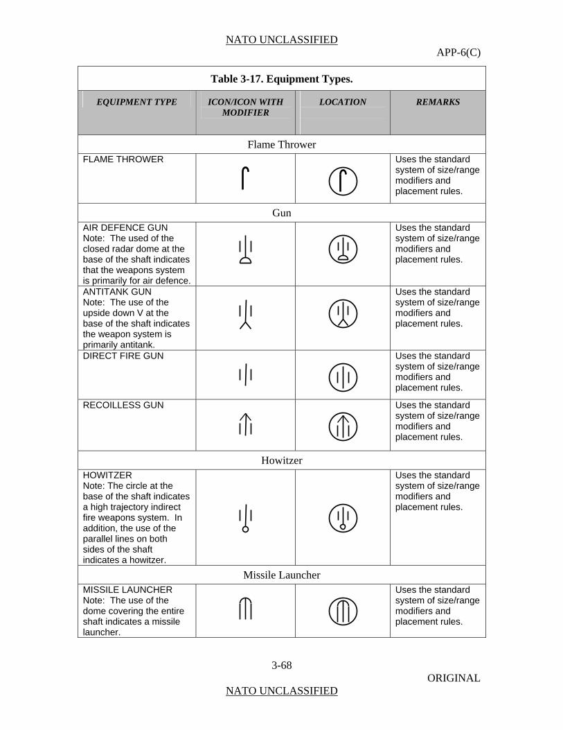
NATO UNCLASSIFIED APP-6(C)
3-68 ORIGINAL
NATO UNCLASSIFIED
Table 3-17. Equipment Types.
EQUIPMENT TYPE ICON/ICON WITH MODIFIER
LOCATION
REMARKS
Flame Thrower
FLAME THROWER
Uses the standard system of size/range modifiers and placement rules.
Gun AIR DEFENCE GUN Note: The used of the closed radar dome at the base of the shaft indicates that the weapons system is primarily for air defence.
Uses the standard system of size/range modifiers and placement rules.
ANTITANK GUN Note: The use of the upside down V at the base of the shaft indicates the weapon system is primarily antitank.
Uses the standard system of size/range modifiers and placement rules.
DIRECT FIRE GUN
Uses the standard system of size/range modifiers and placement rules.
RECOILLESS GUN
Uses the standard system of size/range modifiers and placement rules.
Howitzer HOWITZER Note: The circle at the base of the shaft indicates a high trajectory indirect fire weapons system. In addition, the use of the parallel lines on both sides of the shaft indicates a howitzer.
Uses the standard system of size/range modifiers and placement rules.
Missile Launcher MISSILE LAUNCHER Note: The use of the dome covering the entire shaft indicates a missile launcher.
Uses the standard system of size/range modifiers and placement rules.

NATO UNCLASSIFIED APP-6(C)
3-69 ORIGINAL
NATO UNCLASSIFIED
Table 3-17. Equipment Types.
EQUIPMENT TYPE ICON/ICON WITH MODIFIER
LOCATION
REMARKS
AIR DEFENCE MISSILE LAUNCHER SURFACE-TO-AIR (SAM) Note: The use of the closed radar dome at the base of the shaft indicates that the weapons system is primarily for air defence.
Uses the standard system of size/range modifiers and placement rules.
ANTITANK MISSILE LAUNCHER Note: The use of the upside down V at the base of the shaft indicates the weapon system is primarily antitank.
Uses the standard system of size/range modifiers and placement rules.
SURFACE-TO-SURFACE MISSILE LAUNCHER Note: The use of the line at the base of the shaft indicates that the weapons system is primarily for surface-to-surface.
Uses the standard system of size/range (short, medium, and long range) modifiers and placement rules.
Mortar MORTAR Note: the circle at the base of the shaft indicates a high trajectory indirect fire weapons system or mortar.
Uses the standard system of size/range modifiers and placement rules.
Rocket Launcher SINGLE ROCKET LAUNCHER
Uses the standard system of size/range modifiers and placement rules.
MULTIPLE ROCKET LAUNCHER
Uses the standard system of size/range modifiers and placement rules.

NATO UNCLASSIFIED APP-6(C)
3-70 ORIGINAL
NATO UNCLASSIFIED
Table 3-17. Equipment Types.
EQUIPMENT TYPE ICON/ICON WITH MODIFIER
LOCATION
REMARKS
ANTITANK ROCKET LAUNCHER Note: The use of the upside down V at the base of the shaft indicates the weapon system is primarily antitank.
Uses the standard system of size/range modifiers and placement rules.
Non-Lethal Weapon
NON-LETHAL WEAPON
Non-Lethal Grenade Launcher
TASER
ZZ
None
WATER CANNON
WW
None
Vehicle A self-propelled, boosted, or towed conveyance for transporting a burden on land, sea or through air or space.
Armoured Vehicles ARMOURED FIGHTING VEHICLE (AFV)
None
ARMOURED FIGHTING VEHICLE (AFV) COMMAND AND CONTROL
None
ARMOURED PERSONNEL CARRIER (APC)
None
C2C2
ZZ
WWW
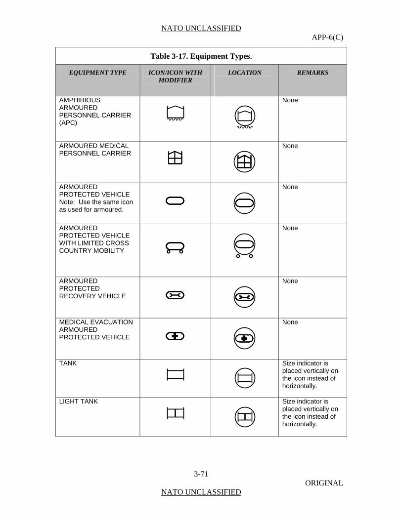
NATO UNCLASSIFIED APP-6(C)
3-71 ORIGINAL
NATO UNCLASSIFIED
Table 3-17. Equipment Types.
EQUIPMENT TYPE ICON/ICON WITH MODIFIER
LOCATION
REMARKS
AMPHIBIOUS ARMOURED PERSONNEL CARRIER (APC)
None
ARMOURED MEDICAL PERSONNEL CARRIER
None
ARMOURED PROTECTED VEHICLE Note: Use the same icon as used for armoured.
None
ARMOURED PROTECTED VEHICLE WITH LIMITED CROSS COUNTRY MOBILITY
None
ARMOURED PROTECTED RECOVERY VEHICLE
None
MEDICAL EVACUATION ARMOURED PROTECTED VEHICLE
None
TANK
Size indicator is placed vertically on the icon instead of horizontally.
LIGHT TANK
Size indicator is placed vertically on the icon instead of horizontally.
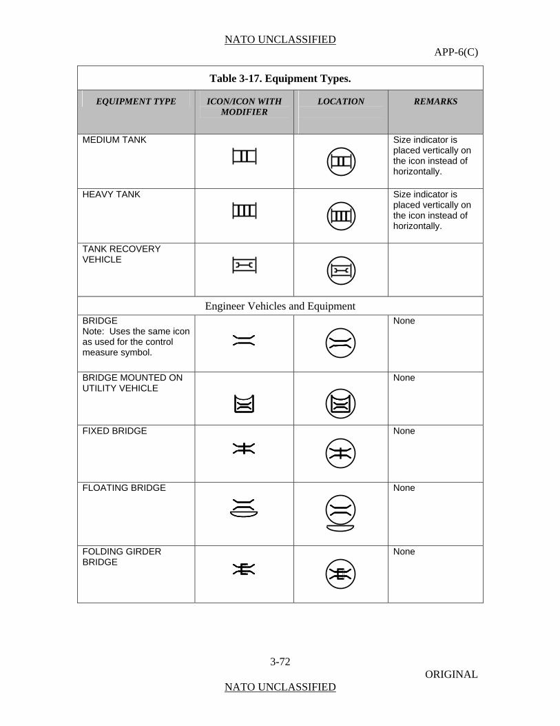
NATO UNCLASSIFIED APP-6(C)
3-72 ORIGINAL
NATO UNCLASSIFIED
Table 3-17. Equipment Types.
EQUIPMENT TYPE ICON/ICON WITH MODIFIER
LOCATION
REMARKS
MEDIUM TANK
Size indicator is placed vertically on the icon instead of horizontally.
HEAVY TANK
Size indicator is placed vertically on the icon instead of horizontally.
TANK RECOVERY VEHICLE
Engineer Vehicles and Equipment BRIDGE Note: Uses the same icon as used for the control measure symbol.
None
BRIDGE MOUNTED ON UTILITY VEHICLE
None
FIXED BRIDGE
None
FLOATING BRIDGE
None
FOLDING GIRDER BRIDGE
None
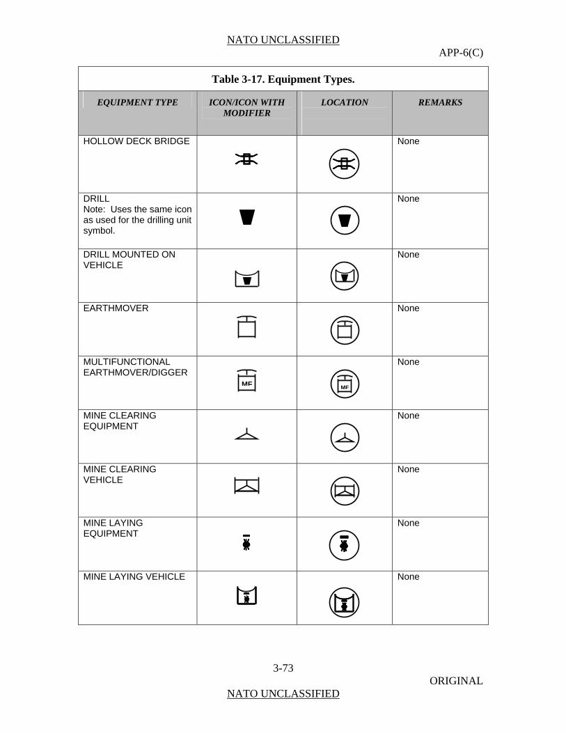
NATO UNCLASSIFIED APP-6(C)
3-73 ORIGINAL
NATO UNCLASSIFIED
Table 3-17. Equipment Types.
EQUIPMENT TYPE ICON/ICON WITH MODIFIER
LOCATION
REMARKS
HOLLOW DECK BRIDGE
None
DRILL Note: Uses the same icon as used for the drilling unit symbol.
None
DRILL MOUNTED ON VEHICLE
None
EARTHMOVER
None
MULTIFUNCTIONAL EARTHMOVER/DIGGER
None
MINE CLEARING EQUIPMENT
None
MINE CLEARING VEHICLE
None
MINE LAYING EQUIPMENT
None
MINE LAYING VEHICLE
None
MF MF

NATO UNCLASSIFIED APP-6(C)
3-74 ORIGINAL
NATO UNCLASSIFIED
Table 3-17. Equipment Types.
EQUIPMENT TYPE ICON/ICON WITH MODIFIER
LOCATION
REMARKS
Utility Vehicle Multi-purpose vehicle capable of moving troops but may be used in command and control, logistics, casualty evacuation or other roles.
UTILITY VEHICLE
None
MEDICAL VEHICLE
None
MEDICAL EVACUATION
None
MOBILE EMERGENCY PHYSICIAN
None
BUS
BB
None
LIMITED CROSS-COUNTRY TRUCK
None
CROSS-COUNTRY TRUCK
None
SEMI-TRAILER TRUCK
None
BBB
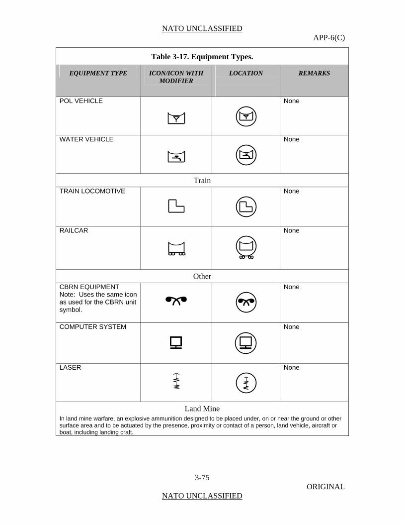
NATO UNCLASSIFIED APP-6(C)
3-75 ORIGINAL
NATO UNCLASSIFIED
Table 3-17. Equipment Types.
EQUIPMENT TYPE ICON/ICON WITH MODIFIER
LOCATION
REMARKS
POL VEHICLE
None
WATER VEHICLE
None
Train
TRAIN LOCOMOTIVE
None
RAILCAR
None
Other
CBRN EQUIPMENT Note: Uses the same icon as used for the CBRN unit symbol.
None
COMPUTER SYSTEM
None
LASER
None
Land Mine In land mine warfare, an explosive ammunition designed to be placed under, on or near the ground or other surface area and to be actuated by the presence, proximity or contact of a person, land vehicle, aircraft or boat, including landing craft.

NATO UNCLASSIFIED APP-6(C)
3-76 ORIGINAL
NATO UNCLASSIFIED
Table 3-17. Equipment Types.
EQUIPMENT TYPE ICON/ICON WITH MODIFIER
LOCATION
REMARKS
LAND MINE (UNSPECIFIED) Note: Uses the same icon as used for the control measure symbol.
None
ANTIPERSONNEL LAND MINE In land mine warfare, a mine designed to be exploded by the presence, proximity or contact of a person and that will incapacitate, wound or kill one or more persons. (AAP-19)
Note: Uses the same icon as used for the control measure symbol. Note: Uses the same icon as used for the control measure symbol.
ANTITANK LAND MINE A mine designed to immobilize or destroy a tank. (AAP-19)
Note: Uses the same icon as used for the control measure symbol.
IMPROVISED EXPLOSIVE DEVICE (IED) A device placed or fabricated in an improvised manner incorporating destructive, lethal, noxious, pyrotechnic or incendiary chemicals and designed to destroy, incapacitate, harass or distract. It may incorporate military stores, but is normally devised from non-military components.
IED
None
Sensor Equipment which detects, and may indicate, and/or record objects and activities by means of energy or particles emitted, reflected, or modified by objects. SENSOR
None
SENSOR EMPLACED
None
IEDIED
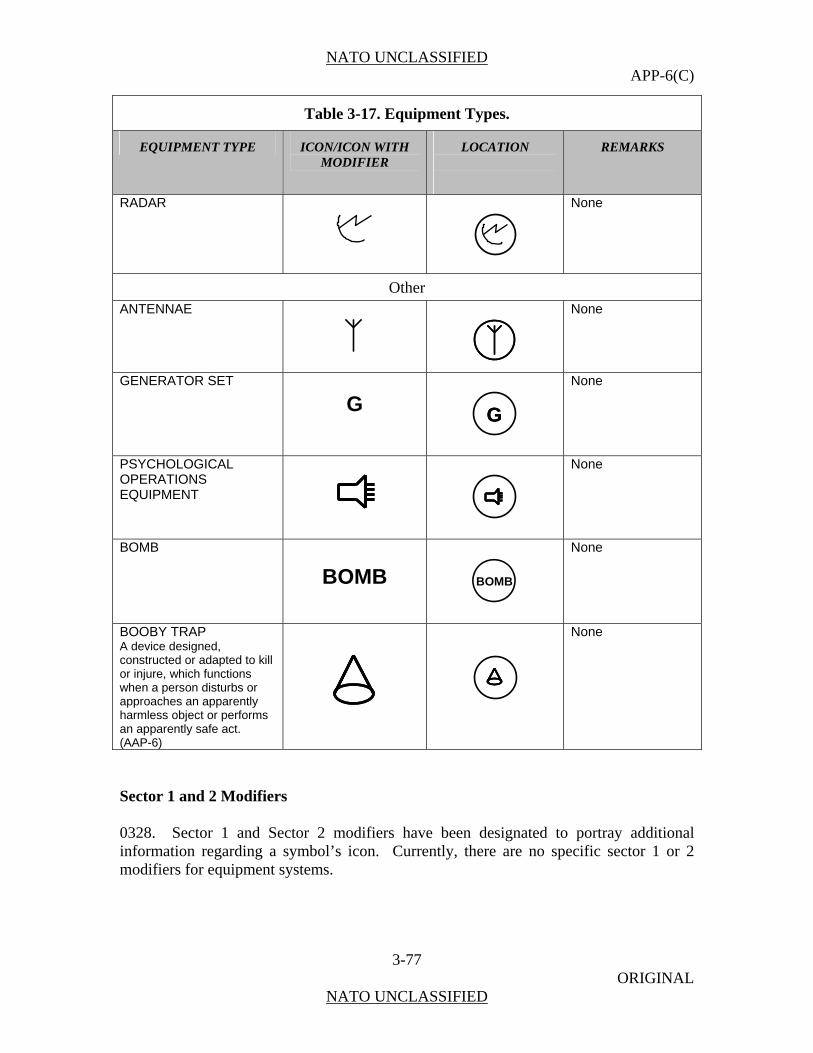
NATO UNCLASSIFIED APP-6(C)
3-77 ORIGINAL
NATO UNCLASSIFIED
Table 3-17. Equipment Types.
EQUIPMENT TYPE ICON/ICON WITH MODIFIER
LOCATION
REMARKS
RADAR
None
Other
ANTENNAE
None
GENERATOR SET
G
None
PSYCHOLOGICAL OPERATIONS EQUIPMENT
None
BOMB BOMB
BOMB
None
BOOBY TRAP A device designed, constructed or adapted to kill or injure, which functions when a person disturbs or approaches an apparently harmless object or performs an apparently safe act. (AAP-6)
None
Sector 1 and 2 Modifiers 0328. Sector 1 and Sector 2 modifiers have been designated to portray additional information regarding a symbol’s icon. Currently, there are no specific sector 1 or 2 modifiers for equipment systems.
GG

NATO UNCLASSIFIED APP-6(C)
3-78 ORIGINAL
NATO UNCLASSIFIED
Mobility Indicator Amplifiers 0329. Table 3-18 provides mobility indicator amplifiers for the equipment types for Field R for equipment symbols.
Table 3-18. Mobility Indicator (Field R).
MOBILITY TYPE
ICON LOCATION (UNFRAMED)
LOCATION
(FRAMED)
AMPHIBIOUS
BARGE
OVER-SNOW (PRIME MOVER)
PACK ANIMAL(S)
RAILWAY
SLED
TOWED

NATO UNCLASSIFIED APP-6(C)
3-79 ORIGINAL
NATO UNCLASSIFIED
Table 3-18. Mobility Indicator (Field R).
MOBILITY TYPE
ICON LOCATION (UNFRAMED)
LOCATION
(FRAMED)
TRACKED
WHEELED (CROSS COUNTRY)
WHEELED (LIMITED MOBILITY)
WHEELED AND TRACKED
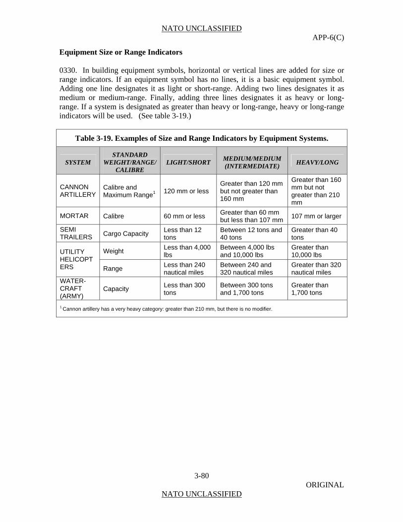
NATO UNCLASSIFIED APP-6(C)
3-80 ORIGINAL
NATO UNCLASSIFIED
Equipment Size or Range Indicators 0330. In building equipment symbols, horizontal or vertical lines are added for size or range indicators. If an equipment symbol has no lines, it is a basic equipment symbol. Adding one line designates it as light or short-range. Adding two lines designates it as medium or medium-range. Finally, adding three lines designates it as heavy or long-range. If a system is designated as greater than heavy or long-range, heavy or long-range indicators will be used. (See table 3-19.)
Table 3-19. Examples of Size and Range Indicators by Equipment Systems.
SYSTEM STANDARD
WEIGHT/RANGE/ CALIBRE
LIGHT/SHORT MEDIUM/MEDIUM (INTERMEDIATE)
HEAVY/LONG
CANNON ARTILLERY
Calibre and Maximum Range1 120 mm or less
Greater than 120 mm but not greater than 160 mm
Greater than 160 mm but not greater than 210 mm
MORTAR Calibre 60 mm or less Greater than 60 mm but less than 107 mm
107 mm or larger
SEMI TRAILERS Cargo Capacity
Less than 12 tons
Between 12 tons and 40 tons
Greater than 40 tons
Weight Less than 4,000 lbs
Between 4,000 lbs and 10,000 lbs
Greater than 10,000 lbs UTILITY
HELICOPTERS Range
Less than 240 nautical miles
Between 240 and 320 nautical miles
Greater than 320 nautical miles
WATER-CRAFT (ARMY)
Capacity Less than 300 tons
Between 300 tons and 1,700 tons
Greater than 1,700 tons
1 Cannon artillery has a very heavy category: greater than 210 mm, but there is no modifier.

NATO UNCLASSIFIED APP-6(C)
3-81 ORIGINAL
NATO UNCLASSIFIED
Section IV
Land Installation Symbols General 0331. Installations are sites that incorporate permanent, semi-permanent, and temporary structures. This chapter establishes a single standard system for the development of a variety of installation symbols. Avoid using any symbols, or combinations and modifications of symbols, different from those in this publication. If, after searching the doctrinal symbols and modifiers in this publication, a new symbol must be created, explain it in an accompanying legend. Composition of Installation Symbols 0332. An installation symbol is composed of a frame, colour (fill), installation icon, text or graphic modifiers (figure 3-17), and text or graphic amplifiers. (See table 3-20 for the steps used to build installation symbols.)
Figure 3-17. Installation Symbol Composition.
Frame Text Amplifier
CO
Icon
Color
Modifier
ST10031944
Frame Text Amplifier
COCO
Icon
Colour
Modifier
ST10031944

NATO UNCLASSIFIED APP-6(C)
3-82 ORIGINAL
NATO UNCLASSIFIED
Table 3-20. Building Installation Symbols.
Step # Step Example
Step 1. Choose the frame according to standard identity.
Land Installation Frame Shapes and Standard Identity
STANDARDIDENTITY
FRIENDLY HOSTILE NEUTRAL UNKNOWN PENDING ASSUMEDFRIEND
SUSPECT
FRAME
STANDARDIDENTITY
FRIENDLY HOSTILE NEUTRAL UNKNOWN PENDING ASSUMEDFRIEND
SUSPECT
FRAME
Steps 2 Choose and add main sector icon.
Step 3. Choose and add a modifier in either sector 1 or sector 2 if applicable or deemed necessary for visualization.
Step 4. Choose and add a second modifier in either sector 1 or sector 2 if applicable or deemed necessary for visualization. NOTE: Only one modifier is permitted per modifier position.
There are no specific sector 2 modifiers at this time.
Land Installation Symbol Fields
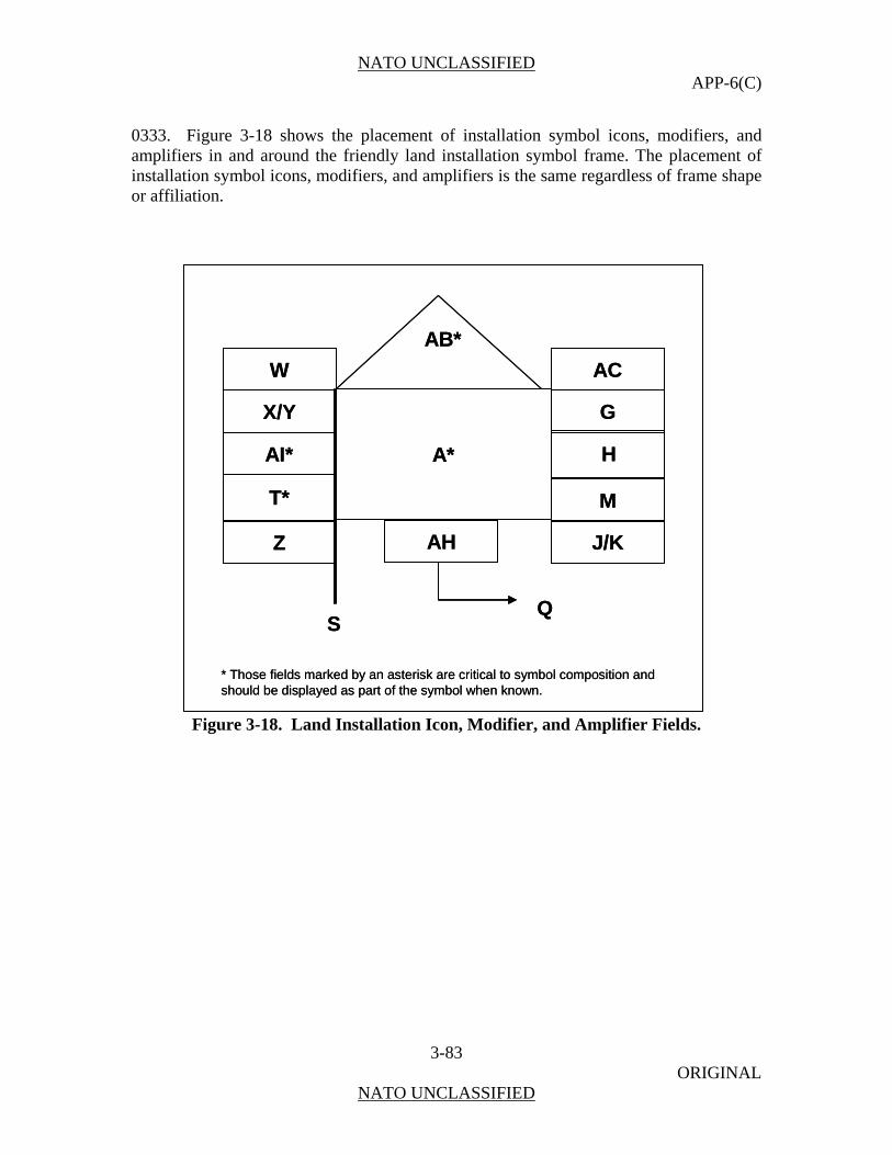
NATO UNCLASSIFIED APP-6(C)
3-83 ORIGINAL
NATO UNCLASSIFIED
0333. Figure 3-18 shows the placement of installation symbol icons, modifiers, and amplifiers in and around the friendly land installation symbol frame. The placement of installation symbol icons, modifiers, and amplifiers is the same regardless of frame shape or affiliation.
W
X/Y
AI*
T*
Z AH
AC
G
H
M
J/K
QS
A*
AB*
* Those fields marked by an asterisk are critical to symbol composition and should be displayed as part of the symbol when known.
W
X/Y
AI*
T*
Z AH
AC
G
H
M
J/K
QS
A*
AB*
* Those fields marked by an asterisk are critical to symbol composition and should be displayed as part of the symbol when known.
Figure 3-18. Land Installation Icon, Modifier, and Amplifier Fields.

NATO UNCLASSIFIED APP-6(C)
3-84 ORIGINAL
NATO UNCLASSIFIED
Location of Icons and Modifiers inside the Octagon (Field A) for Land Installation Symbols 0334. For land installation symbols, the octagon as described in Chapter 1 in paragraph 0116 serves as the foundation for placement of icons and modifiers. The octagon is divided into sectors. The three sectors specify where icons and modifiers are positioned and how much space is available for sizing of icons and modifiers. Figure 3-19 provides examples showing the sectors for each of the frame shape types. The lettering size for text icons and modifiers will vary based on the number of letters used.
FRIENDLY HOSTILE
NEUTRAL UNKNOWN
MAIN
1
2
MAIN
1
2
MAIN
1
2
MAIN
1
2
FRIENDLY HOSTILE
NEUTRAL UNKNOWN
MAIN
1
2
MAIN
1
2
MAIN
1
2
MAIN
1
2
MAIN
1
2
MAIN
1
2
MAIN
1
2
MAIN
1
2
MAIN
1
2
MAIN
1
2
MAIN
1
2
MAIN
1
2
MAIN
1
2
MAIN
1
2
MAIN
1
2
MAIN
1
2
MAIN
1
2
MAIN
1
2
Figure 3-19. Location of Icons and Modifiers.
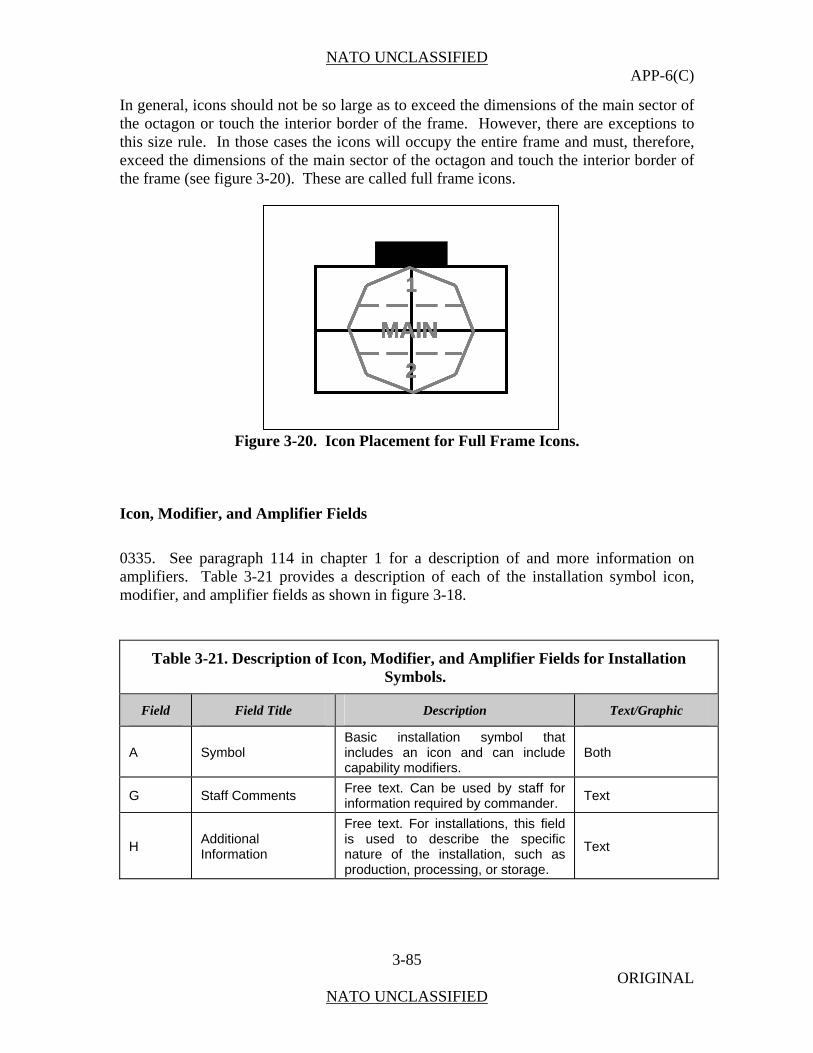
NATO UNCLASSIFIED APP-6(C)
3-85 ORIGINAL
NATO UNCLASSIFIED
In general, icons should not be so large as to exceed the dimensions of the main sector of the octagon or touch the interior border of the frame. However, there are exceptions to this size rule. In those cases the icons will occupy the entire frame and must, therefore, exceed the dimensions of the main sector of the octagon and touch the interior border of the frame (see figure 3-20). These are called full frame icons.
MAIN
1
2
MAIN
1
2
MAIN
1
2
MAIN
1
2
MAIN
1
2
Figure 3-20. Icon Placement for Full Frame Icons.
Icon, Modifier, and Amplifier Fields
0335. See paragraph 114 in chapter 1 for a description of and more information on amplifiers. Table 3-21 provides a description of each of the installation symbol icon, modifier, and amplifier fields as shown in figure 3-18.
Table 3-21. Description of Icon, Modifier, and Amplifier Fields for Installation Symbols.
Field Field Title Description Text/Graphic
A Symbol Basic installation symbol that includes an icon and can include capability modifiers.
Both
G Staff Comments Free text. Can be used by staff for information required by commander.
Text
H Additional Information
Free text. For installations, this field is used to describe the specific nature of the installation, such as production, processing, or storage.
Text
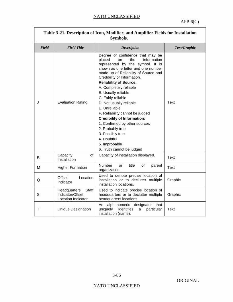
NATO UNCLASSIFIED APP-6(C)
3-86 ORIGINAL
NATO UNCLASSIFIED
Table 3-21. Description of Icon, Modifier, and Amplifier Fields for Installation Symbols.
Field Field Title Description Text/Graphic
J Evaluation Rating
Degree of confidence that may be placed on the information represented by the symbol. It is shown as one letter and one number made up of Reliability of Source and Credibility of Information. Reliability of Source: A. Completely reliable B. Usually reliable C. Fairly reliable D. Not usually reliable E. Unreliable F. Reliability cannot be judged Credibility of Information: 1. Confirmed by other sources 2. Probably true 3. Possibly true 4. Doubtful 5. Improbable 6. Truth cannot be judged
Text
K Capacity of Installation
Capacity of installation displayed. Text
M Higher Formation Number or title of parent organization.
Text
Q Offset Location Indicator
Used to denote precise location of installation or to declutter multiple installation locations.
Graphic
S Headquarters Staff Indicator/Offset Location Indicator
Used to indicate precise location of headquarters or to declutter multiple headquarters locations.
Graphic
T Unique Designation An alphanumeric designator that uniquely identifies a particular installation (name).
Text
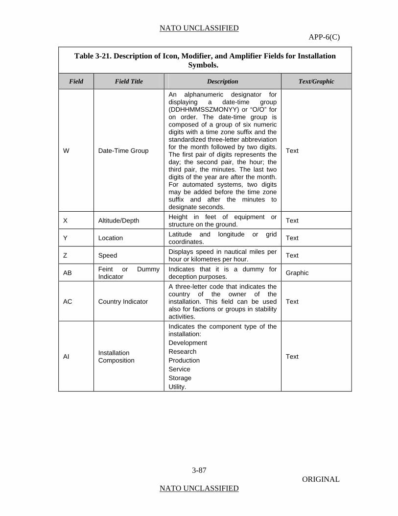
NATO UNCLASSIFIED APP-6(C)
3-87 ORIGINAL
NATO UNCLASSIFIED
Table 3-21. Description of Icon, Modifier, and Amplifier Fields for Installation Symbols.
Field Field Title Description Text/Graphic
W Date-Time Group
An alphanumeric designator for displaying a date-time group (DDHHMMSSZMONYY) or “O/O” for on order. The date-time group is composed of a group of six numeric digits with a time zone suffix and the standardized three-letter abbreviation for the month followed by two digits. The first pair of digits represents the day; the second pair, the hour; the third pair, the minutes. The last two digits of the year are after the month. For automated systems, two digits may be added before the time zone suffix and after the minutes to designate seconds.
Text
X Altitude/Depth Height in feet of equipment or structure on the ground.
Text
Y Location Latitude and longitude or grid coordinates.
Text
Z Speed Displays speed in nautical miles per hour or kilometres per hour.
Text
AB Feint or Dummy Indicator
Indicates that it is a dummy for deception purposes.
Graphic
AC Country Indicator
A three-letter code that indicates the country of the owner of the installation. This field can be used also for factions or groups in stability activities.
Text
AI Installation Composition
Indicates the component type of the installation: Development Research Production Service Storage Utility.
Text

NATO UNCLASSIFIED APP-6(C)
3-88 ORIGINAL
NATO UNCLASSIFIED
Installation Icons 0336. Table 3-22 provides installation icons for use in land unit symbols in the A area of the symbol. Those icons that appear in the unit and equipment sections of this chapter can be used to create installation symbols.
MAIN
1
2
MAIN
1
2
MAIN
1
2
Figure 3-21. Main Sector Icons.
Table 3-22. Installation Icons.
FUNCTION ICON/MODIFIER LOCATION REMARKS
Airport/Air Base Note: Uses the same icon as used for the APOD/APOE unit symbol.
The transportation and runway icons together represent the airport/air base icon. This is an exception to the general construction rules.
Ammunition Cache
The horizontal line must touch the edge of the frame. This is an exception to the general construction rules.
Black List Location
BLK
None
BLKBLK
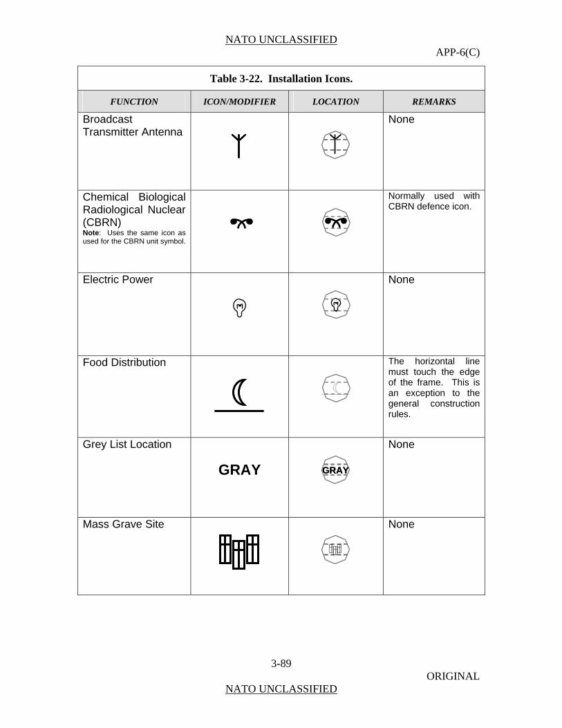
NATO UNCLASSIFIED APP-6(C)
3-89 ORIGINAL
NATO UNCLASSIFIED
Table 3-22. Installation Icons.
FUNCTION ICON/MODIFIER LOCATION REMARKS
Broadcast Transmitter Antenna
None
Chemical Biological Radiological Nuclear (CBRN) Note: Uses the same icon as used for the CBRN unit symbol.
Normally used with CBRN defence icon.
Electric Power
None
Food Distribution
The horizontal line must touch the edge of the frame. This is an exception to the general construction rules.
Grey List Location
GRAY
None
Mass Grave Site
None
GRAYGRAY

NATO UNCLASSIFIED APP-6(C)
3-90 ORIGINAL
NATO UNCLASSIFIED
Table 3-22. Installation Icons.
FUNCTION ICON/MODIFIER LOCATION REMARKS
Medical Note: Uses the same icon as used for the medical unit symbol.
The medical icon is a full frame icon. It must touch the frame edge. This is an exception to the general construction rules.
Medical Treatment Facility (Hospital) Note: Uses the same icon as used for the medical treatment facility symbol.
The medical treatment facility (hospital) icon is a full frame icon. It must touch the frame edge. This is an exception to the general construction rules.
Mine
None
Nuclear(Non-CBRN) Commercial facility that processes nuclear material.
Can be reduced and used as a modifier.
Nuclear Electric Power
Printed Media
None
Railhead/Railroad Station Note: Uses the same icon as used for the railhead unit symbol.
The transportation and railhead icons together represent the railhead/railroad station icon. This is an exception to the general construction rules.
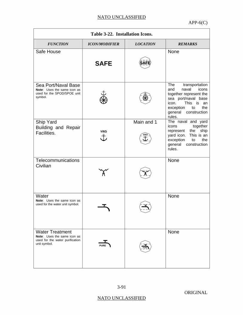
NATO UNCLASSIFIED APP-6(C)
3-91 ORIGINAL
NATO UNCLASSIFIED
Table 3-22. Installation Icons.
FUNCTION ICON/MODIFIER LOCATION REMARKS
Safe House
SAFE
None
Sea Port/Naval Base Note: Uses the same icon as used for the SPOD/SPOE unit symbol.
The transportation and naval icons together represent the sea port/naval base icon. This is an exception to the general construction rules.
Ship Yard Building and Repair Facilities.
Main and 1
The naval and yard icons together represent the ship yard icon. This is an exception to the general construction rules.
Telecommunications Civilian
None
Water Note: Uses the same icon as used for the water unit symbol.
None
Water Treatment Note: Uses the same icon as used for the water purification unit symbol.
None
YRDYRD
PUREPURE
SAFESAFE
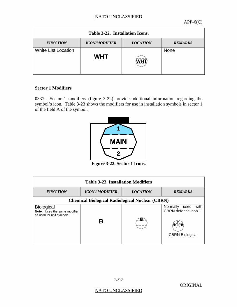
NATO UNCLASSIFIED APP-6(C)
3-92 ORIGINAL
NATO UNCLASSIFIED
Table 3-22. Installation Icons.
FUNCTION ICON/MODIFIER LOCATION REMARKS
White List Location
WHT
None
Sector 1 Modifiers 0337. Sector 1 modifiers (figure 3-22) provide additional information regarding the symbol’s icon. Table 3-23 shows the modifiers for use in installation symbols in sector 1 of the field A of the symbol.
MAIN
1
2
MAIN
1
2
MAIN
1
2
Figure 3-22. Sector 1 Icons.
Table 3-23. Installation Modifiers
FUNCTION ICON / MODIFIER LOCATION REMARKS
Chemical Biological Radiological Nuclear (CBRN)
Biological Note: Uses the same modifier as used for unit symbols.
B
Normally used with CBRN defence icon.
CBRN Biological
B B
WHTWHT
BB

NATO UNCLASSIFIED APP-6(C)
3-93 ORIGINAL
NATO UNCLASSIFIED
Table 3-23. Installation Modifiers
FUNCTION ICON / MODIFIER LOCATION REMARKS
Chemical Note: Uses the same modifier as used for unit symbols.
C
Normally used with CBRN defence icon.
CBRN Chemical
Nuclear Note: Uses the same modifier as used for unit symbols.
N
Normally used with CBRN defence icon.
CBRN Nuclear
Electric Power
Electric Power Coal
CO
Normally used with electric power icon.
Coal Electric Power
Electric Power Geothermal
GT
Normally used with electric power icon.
Geothermal Electric
Power Electric Power Hydroelectric
HY
Normally used with electric power icon.
Hydroelectric Electric
Power
HY
CO CO
GT
N N
C C CC
NN
COCO
GT
HY

NATO UNCLASSIFIED APP-6(C)
3-94 ORIGINAL
NATO UNCLASSIFIED
Table 3-23. Installation Modifiers
FUNCTION ICON / MODIFIER LOCATION REMARKS
Electric Power Natural Gas
NG
Normally used with electric power icon.
Natural Gas Electric
Power Electric Power Petroleum Note: Uses the same icon as used for the POL unit symbol.
Can be used with electric power icon.
Petroleum Electric
Power
Telecommunications
Telecommunications Civilian Radio
R
None
Telecommunications Civilian Telephone
T
None
Telecommunications Civilian Television
TV
None
Sector 2 Modifiers 0338. Sector 2 modifiers can also provide additional information pertaining the symbol’s icon. There are no specific sector 2 modifiers at this time.
NG NG
TV
T
R

NATO UNCLASSIFIED APP-6(C)
4-1 ORIGINAL
NATO UNCLASSIFIED
CHAPTER 4
MARITIME SYMBOLS
Scope
0401. This chapter covers symbols for operations in the maritime domain.
Characteristics of Symbols for in the Maritime Domain
0402. The maritime domain is composed of the sea surface and subsurface battle dimensions.
0403. In the maritime domain, a ship is both a unit and equipment and is normally represented by a surface or subsurface icon with equipment frame. Non-manned equipment exists at the surface and in the subsurface dimension in stationary or moving sensor carriers (autonomous underwater vehicles [AUV]) or stationary or moving weapons (mines and torpedoes).
0404. The surface dimension contains a multitude of non-military ships and stationary objects (e.g. oil rigs), which are the primary objects of military operations (protect, control, deny, access, and destroy).
Content and Structure
0405. This chapter provides the basics for building maritime symbols. The chapter is divided into two sections. Section I covers sea surface symbols and Section II sea subsurface symbols. Each section contains both military and non-military, civilian symbols.
0406. The symbols mentioned above are, accordingly, subdivided into:
a. units, equipment and objects in maritime surface warfare,
b. units, equipment and objects in maritime subsurface warfare.
0407. Maritime control measure symbols (points, lines, areas, commands, standard positions, emergencies, hazards and sonobuoys) are shown in Chapter 7.
Further Developments
0408. This chapter establishes a single standard for maritime domain symbols. It includes a variety of icons and modifiers. In order to ensure that all icons and modifiers shown here can be depicted in all standard identities, they must fit into the boundaries of the octagon presented in Figure 4-2 and adhere to the rules provided in Chapter 1.

NATO UNCLASSIFIED APP-6(C)
4-2 ORIGINAL
NATO UNCLASSIFIED
SECTION I – SEA SURFACE SYMBOLS
Symbol Subset Structure
0409. The units, equipment, and objects of maritime surface operations as described in paragraph 0403 and 0404 are further subdivided in:
a. military surface objects (units), consisting of: - surface warfare (line ships) units - amphibious warfare units - mine warfare units - task organization units - military non-combatants /auxiliaries and service craft
b. non-military objects (ships, boats and installations)
Composition of Sea Surface Symbols
0410. A sea surface symbol is composed of a frame, colour (fill), functional icons (pictogram and/or letters), modifiers and amplifiers (i.e., labels) (Figure 4-1). Table 4-1 depicts the sea surface symbol composition process.
Figure 4-1. Sea Surface Symbol Composition.
DDG
N
Sector 1 Modifier
Sector 2 Modifier
Colour
Frame
Icon
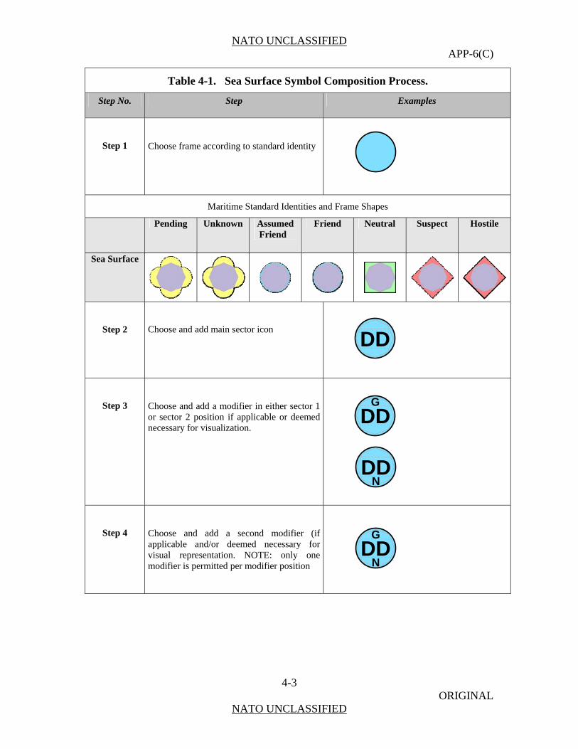
NATO UNCLASSIFIED APP-6(C)
4-3 ORIGINAL
NATO UNCLASSIFIED
Table 4-1. Sea Surface Symbol Composition Process.
Step No. Step Examples
Step 1
Choose frame according to standard identity
Maritime Standard Identities and Frame Shapes
Pending Unknown Assumed Friend
Friend Neutral Suspect Hostile
Sea Surface
Step 2
Choose and add main sector icon
Step 3
Choose and add a modifier in either sector 1 or sector 2 position if applicable or deemed necessary for visualization.
Step 4
Choose and add a second modifier (if applicable and/or deemed necessary for visual representation. NOTE: only one modifier is permitted per modifier position
DD
DDG
DDN
DDG
N

NATO UNCLASSIFIED APP-6(C)
4-4 ORIGINAL
NATO UNCLASSIFIED
Icons and Modifiers
0412. All icons shall be placed within the “MAIN” sector of the bounding octagon. Icons may be re-sized accordingly due to the presence or absence of modifiers in order to optimise legibility. Icons may be single icons or compound icons.
0413. Modifiers may be placed above (octagon sector 1) and below (octagon sector 2) of the icon (see Figure 4-2). Only one modifier may be placed within sector 1 or 2 at a given time. Multiple modifiers in the same position are prohibited due to legibility concerns.
Figure 4-2. Icon and Modifier sectors for Sea Surface Symbols.
Sea Surface Sector 1 Modifiers are used to denote 1) mission area, 2) weapons capability, or 3) asset capability of a given icon. Table 4-2 lists sea surface sector 1 modifiers. The respective icons are shown in table 4-8.
Table 4-2. Sea Surface Sector 1 Modifiers.
Modifier Name Type AAW Antiair Warfare Mission Area ASW Antisubmarine Warfare Mission Area
E Escort Mission Area EW Electronic Warfare Mission Area
ISR Intelligence, Surveillance,
Reconnaissance Mission Area
MCM Mine Countermeasures Mission Area MD Missile Defence Mission Area ME Medical (Facilities Role 2+) Mission Area MW Mine Warfare Mission Area
RMV Remote Multi-Mission
Vehicle Mission Area
SOF Special Operations Force Mission Area
MAIN1
2
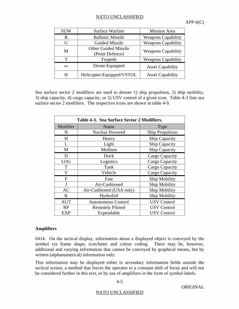
NATO UNCLASSIFIED APP-6(C)
4-5 ORIGINAL
NATO UNCLASSIFIED
SUW Surface Warfare Mission Area B Ballistic Missile Weapons Capability G Guided Missile Weapons Capability
M Other Guided Missile
(Point Defence) Weapons Capability
T Torpedo Weapons Capability Drone-Equipped Asset Capability
H Helicopter-Equipped/VSTOL Asset Capability
Sea surface sector 2 modifiers are used to denote 1) ship propulsion, 2) ship mobility, 3) ship capacity, 4) cargo capacity, or 5) USV control of a given icon. Table 4-3 lists sea surface sector 2 modifiers. The respective icons are shown in table 4-9.
Table 4-3. Sea Surface Sector 2 Modifiers.
Modifier Name Type N Nuclear Powered Ship Propulsion H Heavy Ship Capacity L Light Ship Capacity M Medium Ship Capacity D Dock Cargo Capacity
LOG Logistics Cargo Capacity T Tank Cargo Capacity V Vehicle Cargo Capacity F Fast Ship Mobility J Air-Cushioned Ship Mobility
AC Air-Cushioned (USA only) Ship Mobility K Hydrofoil Ship Mobility
AUT Autonomous Control USV Control RP Remotely Piloted USV Control
EXP Expendable USV Control
Amplifiers
0414. On the tactical display, information about a displayed object is conveyed by the symbol via frame shape, icon/letter and colour coding. There may be, however, additional and varying information that cannot be conveyed by graphical means, but by written (alphanumerical) information only.
This information may be displayed either in secondary information fields outside the tactical screen, a method that forces the operator to a constant shift of focus and will not be considered further in this text, or by use of amplifiers in the form of symbol labels.
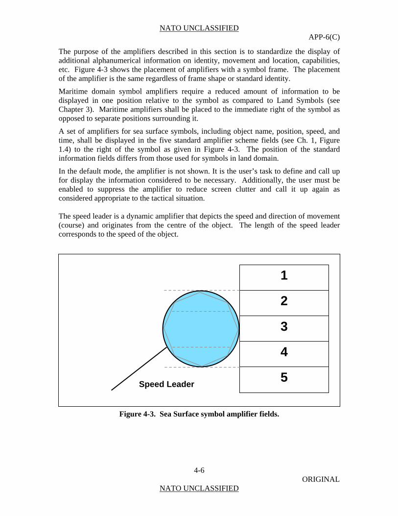
NATO UNCLASSIFIED APP-6(C)
4-6 ORIGINAL
NATO UNCLASSIFIED
The purpose of the amplifiers described in this section is to standardize the display of additional alphanumerical information on identity, movement and location, capabilities, etc. Figure 4-3 shows the placement of amplifiers with a symbol frame. The placement of the amplifier is the same regardless of frame shape or standard identity.
Maritime domain symbol amplifiers require a reduced amount of information to be displayed in one position relative to the symbol as compared to Land Symbols (see Chapter 3). Maritime amplifiers shall be placed to the immediate right of the symbol as opposed to separate positions surrounding it.
A set of amplifiers for sea surface symbols, including object name, position, speed, and time, shall be displayed in the five standard amplifier scheme fields (see Ch. 1, Figure 1.4) to the right of the symbol as given in Figure 4-3. The position of the standard information fields differs from those used for symbols in land domain.
In the default mode, the amplifier is not shown. It is the user’s task to define and call up for display the information considered to be necessary. Additionally, the user must be enabled to suppress the amplifier to reduce screen clutter and call it up again as considered appropriate to the tactical situation. The speed leader is a dynamic amplifier that depicts the speed and direction of movement (course) and originates from the centre of the object. The length of the speed leader corresponds to the speed of the object.
Figure 4-3. Sea Surface symbol amplifier fields.
1
2
3
4
5 Speed Leader

NATO UNCLASSIFIED APP-6(C)
4-7 ORIGINAL
NATO UNCLASSIFIED
Table 4-4 provides the possibilities of information display for military and non-military surface objects by amplifiers.
Table 4-4. Contents of Amplifiers for Sea Surface Symbols.
Field Field Title Description (Alternatives) Prefix (when applicable)
1 Track Number System Track Number TN
2 Name Ships Name, Hull Number or Task Organization Designator (military only), Mission / International call sign
-
3 Position Movement (if speed leader is suppressed) DTG
Course [degrees] /Speed [knots] and/or Bearing [degrees] / Distance [nautical miles] Date-Time Group
-
B/D
4
Identification Country of origin (STANAG 1059 - 3-letter code) or Organization (e.g. UN, NATO, EU)
Any other information (e.g. IFF / AIS)
-
5 Additional Information For friendly units: - Sensor or weapon load, endurance, etc.
For other units: - Credibility of information
-
Sea Surface Icons 0415. Table 4-5 (Military Ships), Table 4-6 (Civilian Vessels), and Table 4-7 (Own Ship) provide the sea surface icon subset. The 2- and 3-letter codes used in the military sea surface icons (Table 4-5) are in accordance with STANAG 1166 (Edition 7). Non-military, civilian sea surface icons (Table 4-6) are displayed with an standard identity colour frame, but a white symbol icon to differentiate from military units. The single letter codes used within the merchant ship icons are derived from the STANAG 1166 as the 3rd letter specifying the type of the merchant ship. For other types of non-military surface vessels, the icons/letter codes of the symbol were chosen without STANAG reference. In order to enable the operator to “de-clutter” a large display,
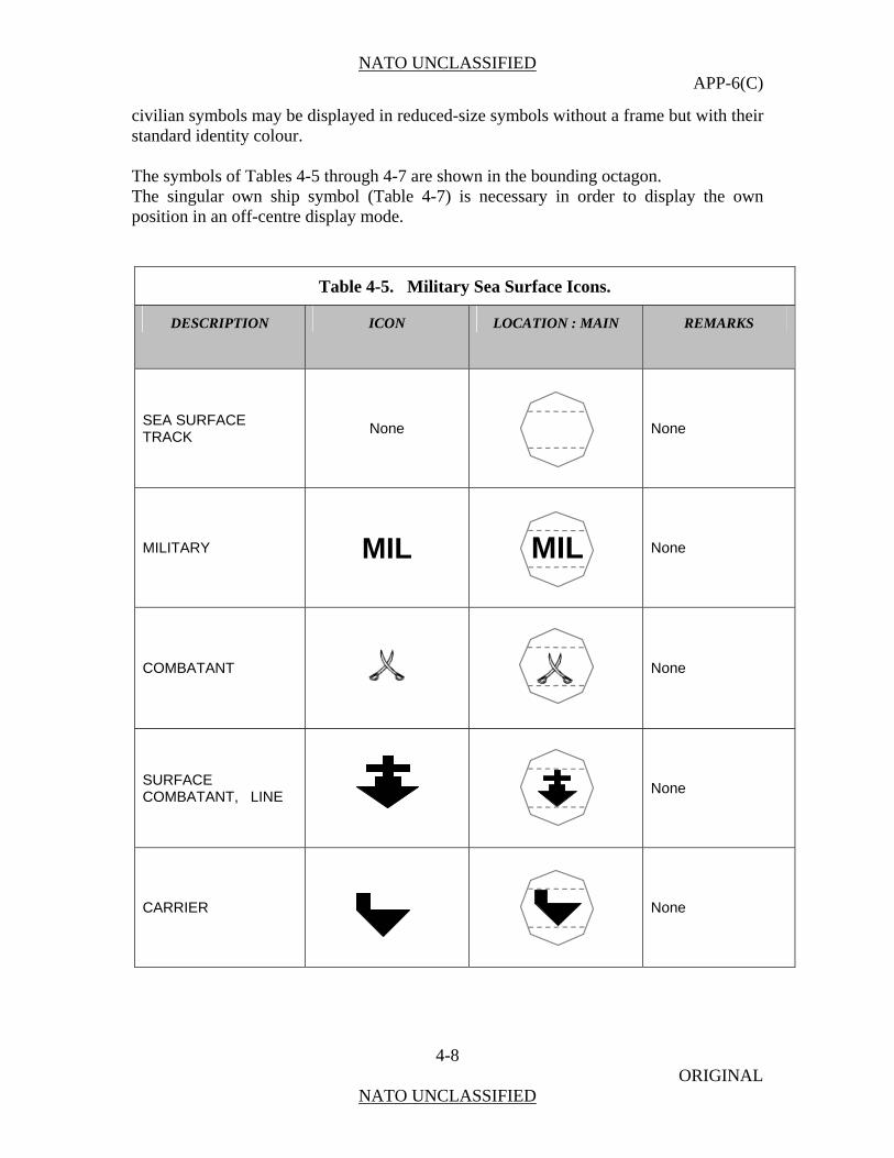
NATO UNCLASSIFIED APP-6(C)
4-8 ORIGINAL
NATO UNCLASSIFIED
civilian symbols may be displayed in reduced-size symbols without a frame but with their standard identity colour. The symbols of Tables 4-5 through 4-7 are shown in the bounding octagon. The singular own ship symbol (Table 4-7) is necessary in order to display the own position in an off-centre display mode.
Table 4-5. Military Sea Surface Icons.
DESCRIPTION ICON LOCATION : MAIN REMARKS
SEA SURFACE TRACK None
None
MILITARY MIL
MIL
None
COMBATANT
None
SURFACE COMBATANT, LINE
None
CARRIER
None
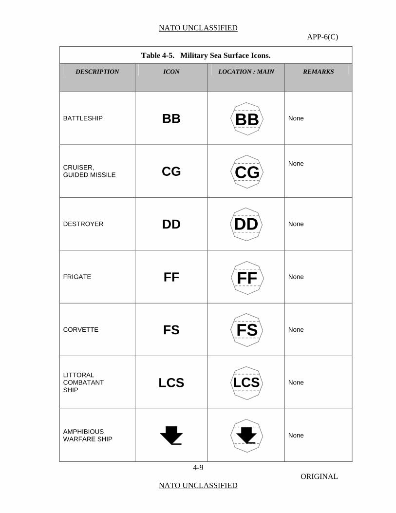
NATO UNCLASSIFIED APP-6(C)
4-9 ORIGINAL
NATO UNCLASSIFIED
Table 4-5. Military Sea Surface Icons.
DESCRIPTION ICON LOCATION : MAIN REMARKS
BATTLESHIP BB
BB
None
CRUISER, GUIDED MISSILE CG
CG
None
DESTROYER DD
DD
None
FRIGATE FF
FF
None
CORVETTE FS
FS
None
LITTORAL COMBATANT SHIP
LCS
LCS
None
AMPHIBIOUS WARFARE SHIP
None
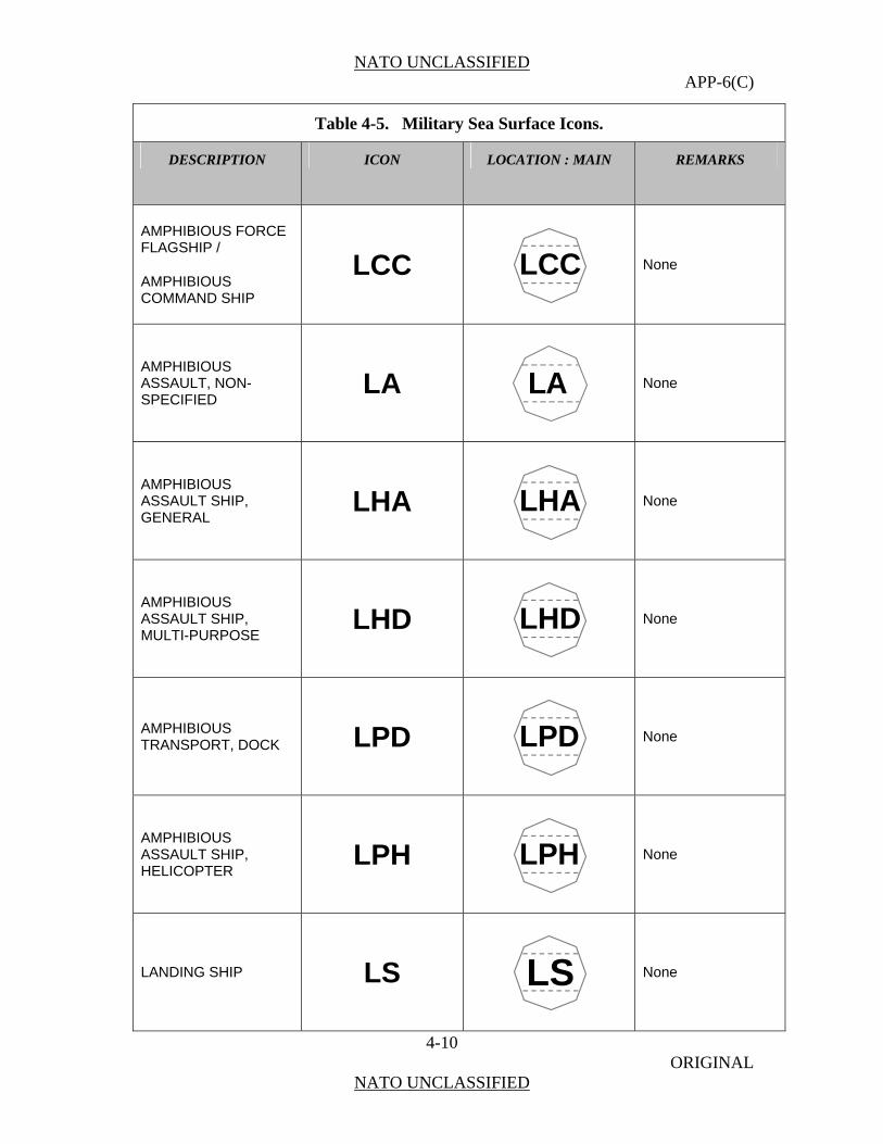
NATO UNCLASSIFIED APP-6(C)
4-10 ORIGINAL
NATO UNCLASSIFIED
Table 4-5. Military Sea Surface Icons.
DESCRIPTION ICON LOCATION : MAIN REMARKS
AMPHIBIOUS FORCE
COMMAND SHIP
LCC FLAGSHIP /
AMPHIBIOUS
LCC
None
AMPHIBIOUS ASSAULT, NON-SPECIFIED
LA LA
None
AMPHIBIOUS ASSAULT SHIP, GENERAL
LHA
LHA
None
AMPHIBIOUS ASSAULT SHIP, MULTI-PURPOSE
LHD
LHD
None
AMPHIBIOUS TRANSPORT, DOCK LPD
LPD
None
AMPHIBIOUS ASSAULT SHIP, HELICOPTER
LPH
LPH
None
LANDING SHIP LS
LS
None
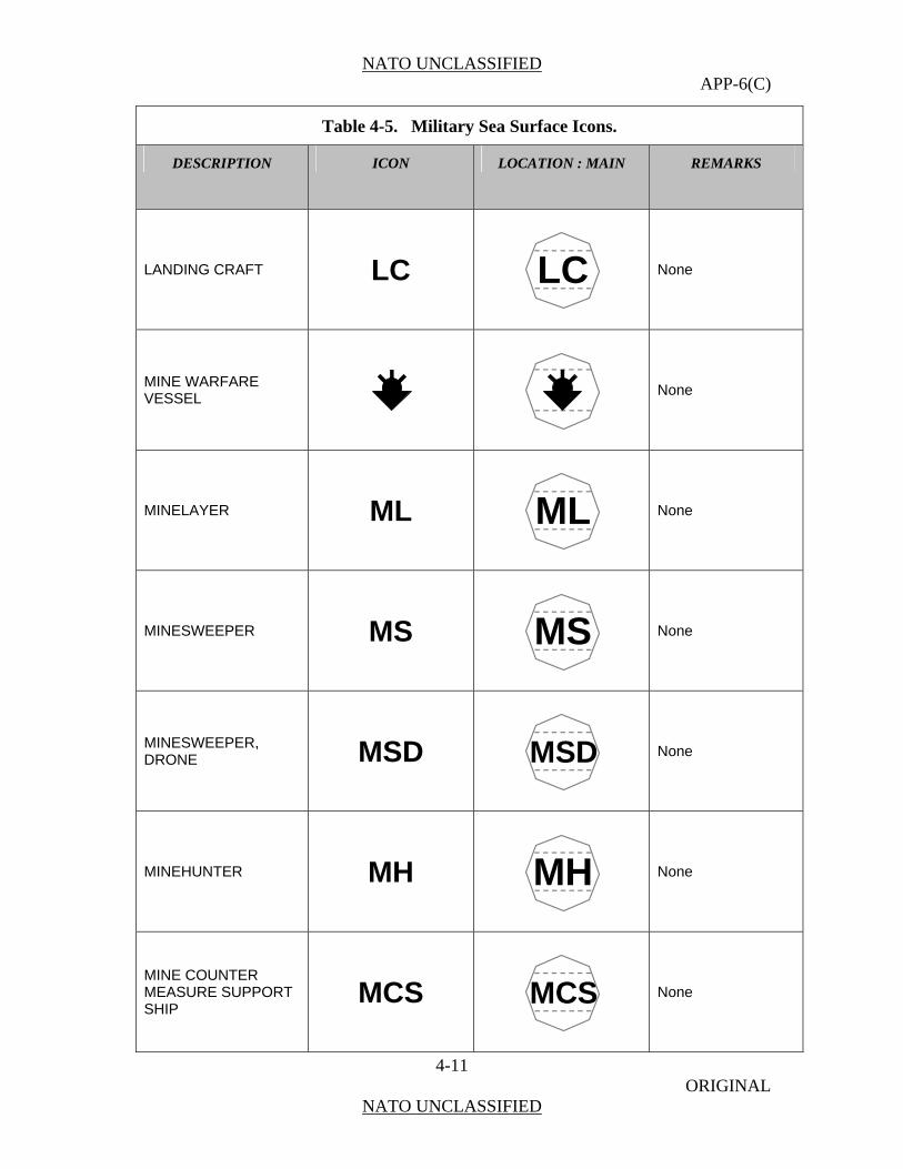
NATO UNCLASSIFIED APP-6(C)
4-11 ORIGINAL
NATO UNCLASSIFIED
Table 4-5. Military Sea Surface Icons.
DESCRIPTION ICON LOCATION : MAIN REMARKS
LANDING CRAFT LC
LC
None
MINE WARFAREVESSEL
None
MINELAYER ML
ML
None
MINESWEEPER MS
MS
None
MINESWEEPER, DRONE MSD
MSD
None
MINEHUNTER MH
MH
None
MINE COUNTER MEASURE SUPPORT SHIP
MCS
MCS
None
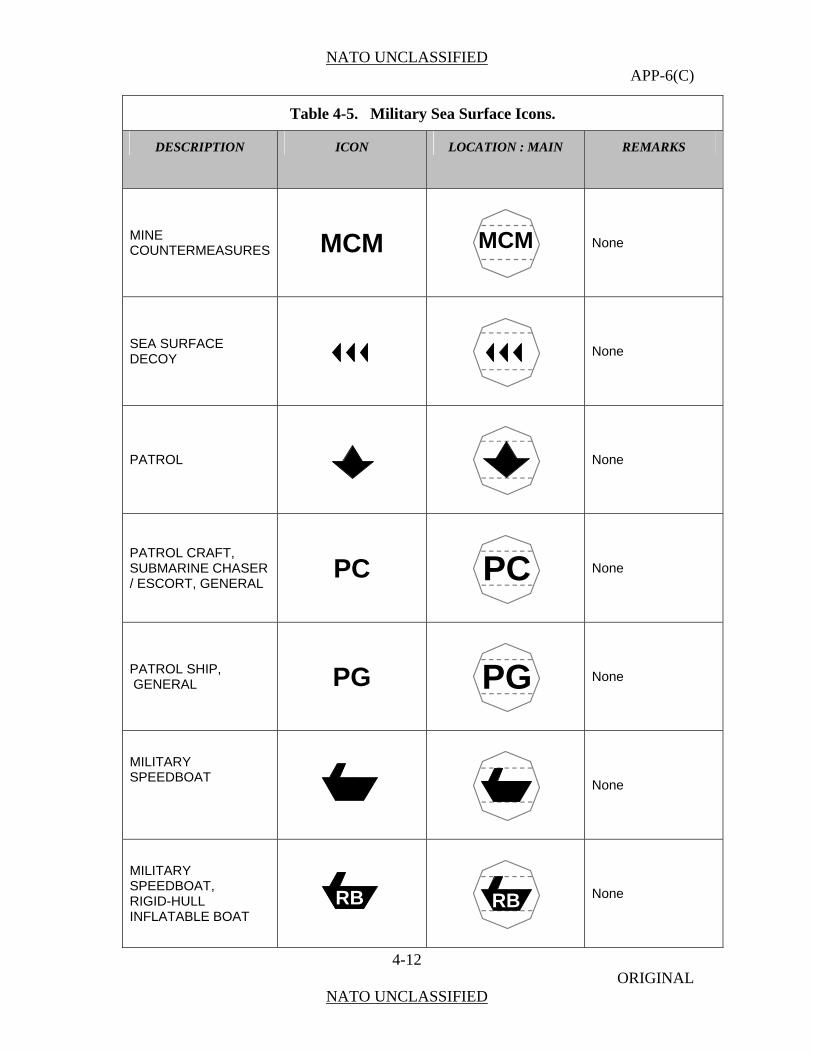
NATO UNCLASSIFIED APP-6(C)
4-12 ORIGINAL
NATO UNCLASSIFIED
Table 4-5. Military Sea Surface Icons.
DESCRIPTION ICON LOCATION : MAIN REMARKS
MINE COUNTERMEASURES MCM
MCM
None
SEA SURFACEDECOY
None
PATROL
None
PATROL CRSUBMARINE CHASER / ESCORT, GENERAL
AFT,
PC
PC
None
PATROL SHIP, GENERAL PG
PG
None
MILITARY
SPEEDBOAT
None
MILITARY SPEEDBOAT, RIGID-HULL INFLATABLE BOAT
RB
RB
None

NATO UNCLASSIFIED APP-6(C)
4-13 ORIGINAL
NATO UNCLASSIFIED
Table 4-5. Military Sea Surface Icons.
DESCRIPTION ICON LOCATION : MAIN REMARKS
MILITARY JETSKI
None
UNMANNED SURFACE WATER VEHICLE
None
NAVY TASK RGANIZATION UNIT,
UNSPECIFIED O
None
NAVY TASK FORCE
TF
TF
None
NAVY TASK GROUP
TG
TG
None
NAVY TASK UNIT
TU
TU
None

NATO UNCLASSIFIED APP-6(C)
4-14 ORIGINAL
NATO UNCLASSIFIED
Table 4-5. Military Sea Surface Icons.
DESCRIPTION ICON LOCATION : MAIN REMARKS
NAVY TASK ELEMENT
TE
TE
None
CONVOY
None
NONCOMBATANT
None
AUXILIARY SHIP, AA GENERAL
AA
None
AMMUNITION SHIP (UNDERWAY
ENT
AE REPLENISHMCAPABLE)
AE
None
STORES SHIP, NAVAL
DS) AF
(DRY GOO
AF
None
AUXILIARY FLAG OR COMMAND SHIP
AGF
AGF
None
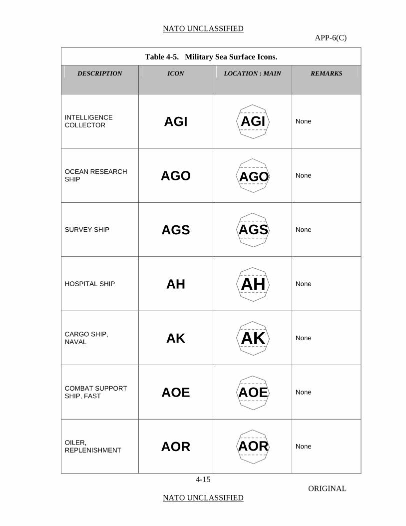
NATO UNCLASSIFIED APP-6(C)
4-15 ORIGINAL
NATO UNCLASSIFIED
Table 4-5. Military Sea Surface Icons.
DESCRIPTION ICON LOCATION : MAIN REMARKS
INTELLIGENCE COLLECTOR AGI
AGI
None
OCEAN RESEARCSHIP
H AGO
AGO
None
SURVEY SHIP AGS
AGS
None
HOSPITAL SHIP AH
AH
None
CARGO SHIP, NAVAL AK
AK
None
COMBAT SUPPOSHIP, FAST
RT AOE
AOE
None
OILER, REPLENISHMENT AOR
AOR
None

NATO UNCLASSIFIED APP-6(C)
4-16 ORIGINAL
NATO UNCLASSIFIED
Table 4-5. Military Sea Surface Icons.
DESCRIPTION ICON LOCATION : MAIN REMARKS
REPAIR SHIP AR
AR
None
SUBMARINE TENDER AS
AS
None
TUG, OCEAN GOING AT
AT
None
SERVICE CRAFYARD, G
T, ENERAL YY
YY
None
BARGE, NOT SELF-PROPELLED YB
YB
None
BARGE,SELF-PROPELLED
YS
YS
None
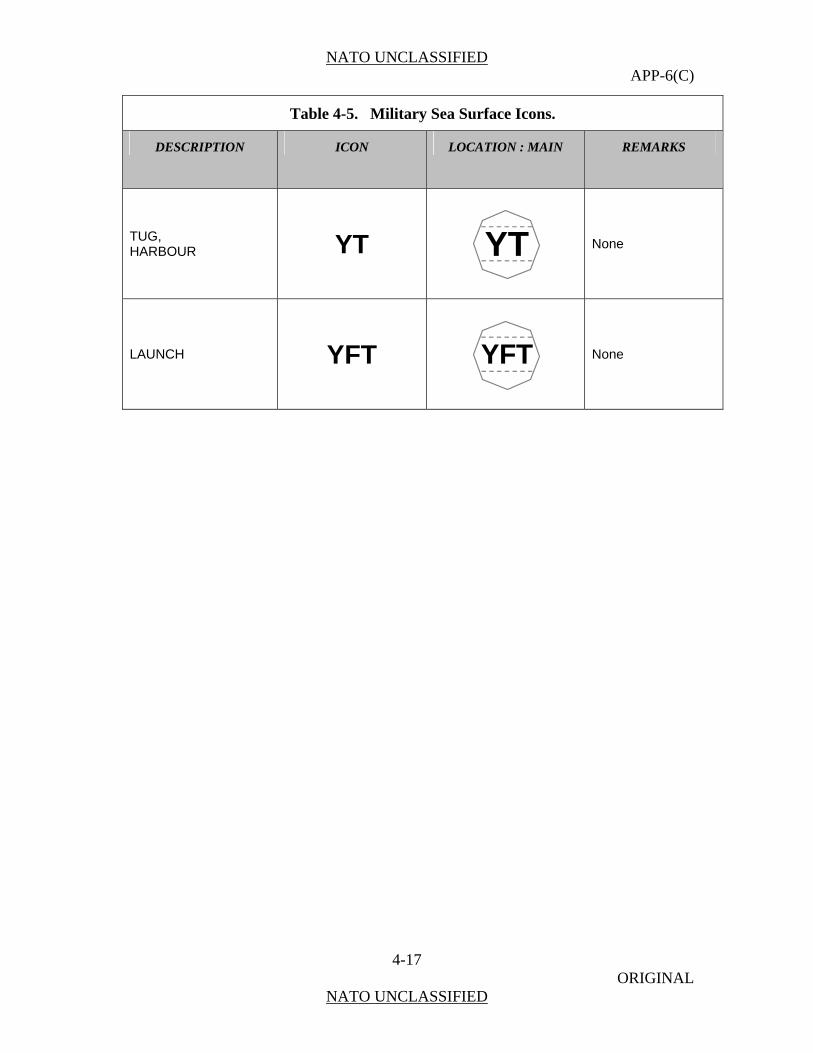
NATO UNCLASSIFIED APP-6(C)
4-17 ORIGINAL
NATO UNCLASSIFIED
Table 4-5. Military Sea Surface Icons.
DESCRIPTION ICON LOCATION : MAIN REMARKS
TUG, HARBOUR YT
YT
None
LAUNCH YFT
YFT
None

NATO UNCLASSIFIED APP-6(C)
4-18 ORIGINAL
NATO UNCLASSIFIED
Table 4-6. Non-Military Surface Icons.
DESCRIPTION ICON LOCATION : MAIN REMARKS
CIVILIAN CIV
CIV
None
MERCHANT SHIP, GENERAL
None
CARGO, GENERAL A
A
None
CONTAINER SHIP C
C
None
DREDGE D
D
None
ROLL ON-ROLL OFF E
E
None
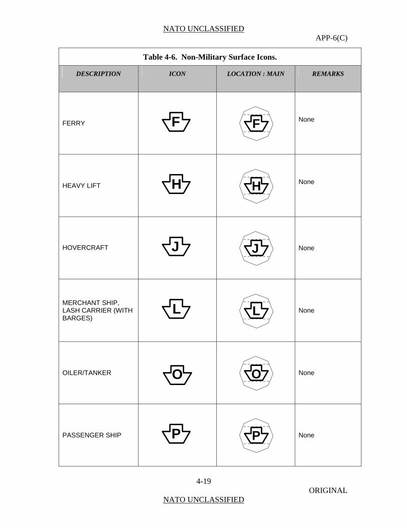
NATO UNCLASSIFIED APP-6(C)
4-19 ORIGINAL
NATO UNCLASSIFIED
Table 4-6. Non-Military Surface Icons.
DESCRIPTION ICON LOCATION : MAIN REMARKS
FERRY F
F
None
HEAVY LIFT H
H
None
HOVERCRAFT
J
J
None
MERCHANT SHIP, LASH CARRIER (WITH BARGES)
L
L
None
OILER/TANKER
O
O
None
PASSENGER SHIP P
P
None
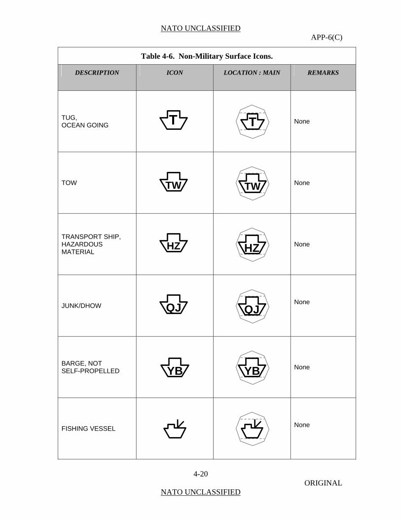
NATO UNCLASSIFIED APP-6(C)
4-20 ORIGINAL
NATO UNCLASSIFIED
Table 4-6. Non-Military Surface Icons.
DESCRIPTION ICON LOCATION : MAIN REMARKS
TUG, OCEAN GOING T
T
None
TOW TW
TW
None
TRANSPORT SHIP,
MATERIAL HAZARDOUS HZ
HZ
None
JUNK/DHOW QJ
QJ
None
BARGE, NOT SELF-PROPELLED YB
YB
None
FISHING VESSEL
None
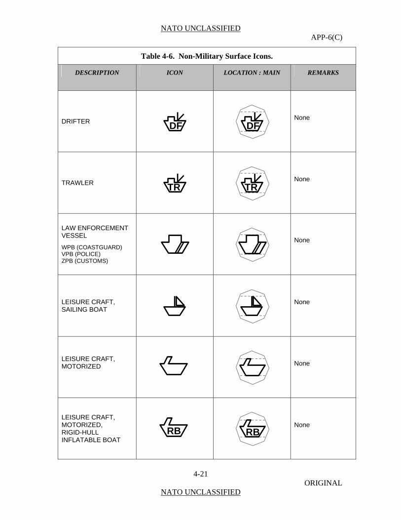
NATO UNCLASSIFIED APP-6(C)
4-21 ORIGINAL
NATO UNCLASSIFIED
Table 4-6. Non-Military Surface Icons.
DESCRIPTION ICON LOCATION : MAIN REMARKS
DRIFTER
DF
DF
None
TRAWLER
TR
TR
None
LAW ENFORCEMENT VESSEL
OASTGUARD) VPB (POLICE) ZPB (CUSTOMS)
WPB (C
None
LEISURE CRAFT, SAILING BOAT
None
LEISURE CRAFT,
MOTORIZED
None
LEISURE CRAFT,
INFLATABLE BOAT
MOTORIZED, RIGID-HULL
RB
RB
None
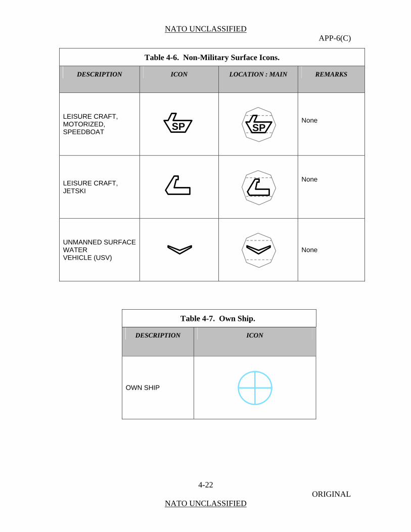
NATO UNCLASSIFIED APP-6(C)
4-22 ORIGINAL
NATO UNCLASSIFIED
Table 4-6. Non-Military Surface Icons.
DESCRIPTION ICON LOCATION : MAIN REMARKS
LEISURE CRAFT,
SPEEDBOAT MOTORIZED,
SP
SP
None
LEISURE CJETSKI
RAFT,
None
UNMANNED SURFACE
VEHICLE (USV) WATER
None
Table 4-7. Own Ship.
DESCRIPTION ICON
OWN SHIP
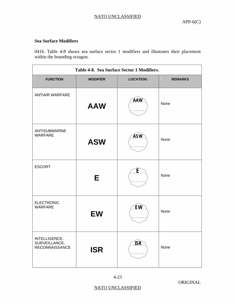
NATO UNCLASSIFIED APP-6(C)
4-23 ORIGINAL
NATO UNCLASSIFIED
Sea Surface Modifiers 0416. Table 4-8 shows sea surface sector 1 modifiers and illustrates their placement within the bounding octagon.
Table 4-8. Sea Surface Sector 1 Modifiers.
FUNCTION MODIFIER LOCATION:
REMARKS
ANTIAIR WARFARE
AAW
AAW
None
ANTISUBMARINE WARFARE
ASW
ASW
None
ESCORT
E
E
None
EW
LECTRONIC ARFARE
EW
EW
None
INTELLIGENCE, SURVEILLANCE, RECONNAISSANCE ISR
ISR
None
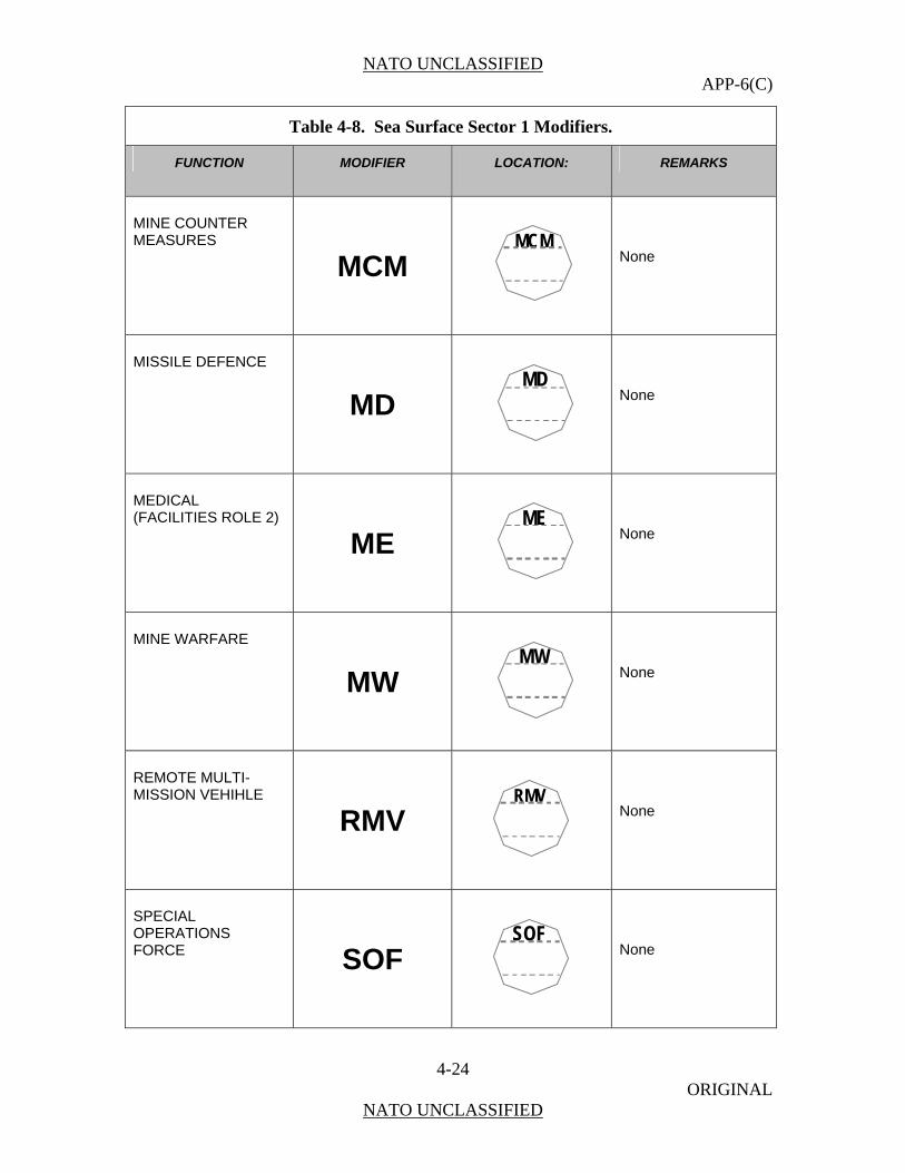
NATO UNCLASSIFIED APP-6(C)
4-24 ORIGINAL
NATO UNCLASSIFIED
Table 4-8. Sea Surface Sector 1 Modifiers.
FUNCTION MODIFIER LOCATION:
REMARKS
MINE COUNTER MEASURES
MCM
MCM
None
MISSILE DEFENCE
MD
MD
None
MEDICAL
ME (FACILITIES ROLE 2)
ME
None
MINE WARFARE
MW
MW
None
REMOTE MULTI-MISSION VEHIHLE
RMV
RMV
None
SPECIAL OPERATIONS FORCE SOF
SOF
None
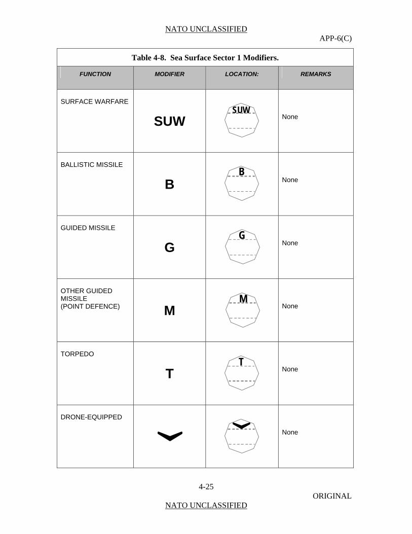
NATO UNCLASSIFIED APP-6(C)
4-25 ORIGINAL
NATO UNCLASSIFIED
Table 4-8. Sea Surface Sector 1 Modifiers.
FUNCTION MODIFIER LOCATION:
REMARKS
SURFACE WARFARE
SUW
SUW
None
BALLISTIC MISSILE
B
B
None
GUIDED MISSILE
G
G
None
OTHER GUIDED MISSILE (POINT DEFENCE) M
M
None
TORPEDO
T
T
None
DRONE-EQUIPPED
None
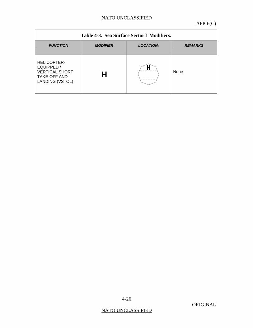
NATO UNCLASSIFIED APP-6(C)
4-26 ORIGINAL
NATO UNCLASSIFIED
Table 4-8. Sea Surface Sector 1 Modifiers.
FUNCTION MODIFIER LOCATION:
REMARKS
HELICOPTER- EQUIPPED / VERTICAL SHORT TAKE-OFF AND LANDING (VSTOL)
H
H
None
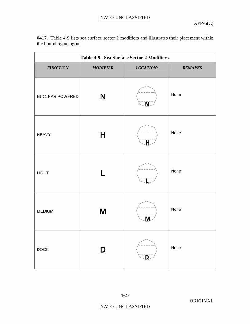
NATO UNCLASSIFIED APP-6(C)
4-27 ORIGINAL
NATO UNCLASSIFIED
0417. Table 4-9 lists sea surface sector 2 modifiers and illustrates their placement within the bounding octagon.
Table 4-9. Sea Surface Sector 2 Modifiers.
FUNCTION MODIFIER LOCATION:
REMARKS
NUCLEAR POWERED N
N
None
HEAVY H
H
None
LIGHT L
L
None
MEDIUM M
M
None
DOCK D
D
None

NATO UNCLASSIFIED APP-6(C)
4-28 ORIGINAL
NATO UNCLASSIFIED
Table 4-9. Sea Surface Sector 2 Modifiers.
FUNCTION MODIFIER LOCATION:
REMARKS
LOGISTICS LOG
LOG
None
TANK T
T
Only in conjunction with amphibious warfare or landing ship symbols.
VEHICLE V
V
Only in conjunction with amphibious warfare or landing ship symbols.
FAST F
F
None
AIR-CUSHIONED J
J
None
AIR-CUSHIONED (USA ONLY) AC
AC
None

NATO UNCLASSIFIED APP-6(C)
4-29 ORIGINAL
NATO UNCLASSIFIED
Table 4-9. Sea Surface Sector 2 Modifiers.
FUNCTION MODIFIER LOCATION:
REMARKS
HYDROFOIL K
K
None
AUTONCONTR
OMOUS OL AUT
AUT
None
REMOTELY PILOTED RP
RP
None
EXPENDABLE EXP
EXP
None

NATO UNCLASSIFIED APP-6(C)
4-30 ORIGINAL
NATO UNCLASSIFIED
SECTION II – SEA SUBSURFACE SYMBOLS Symbol Subset Structure
0416. The units, equipment, and objects of sea subsurface operations as mentioned in 3 are further subd d in
a. military sea subsurface objects (units) submarines non-stationary sensors (i.e., AUV) non-stationary weapons (torpedoes) and decoys stationary weapons (mines) with an additional display mode
thers (e.g., di
b. non-military sea subsurface objects. Composition of Sea Subsurface Symbols
0417. A unit symbol is composed of a frame (in this case the subsurface frame), colour and/ o s) and amplifiers. Figure 4-4 shows an example Howe the area of mine warfare, the status of
“OPERATIONAL/NEUTRALIZED” is displayed by a second icon within the symbol. This is shown in Table 4-17.
paragraph 040 ivide
o
ver)
(fill), icon (pictogramwithout amplifiers.
r letterver, in
Figure 4-4. Sea Subsurface Symbol.
A
R
Sector 1 Modifier
Colour
Frame
Sector 2 Modifier
Icon Speed Leader
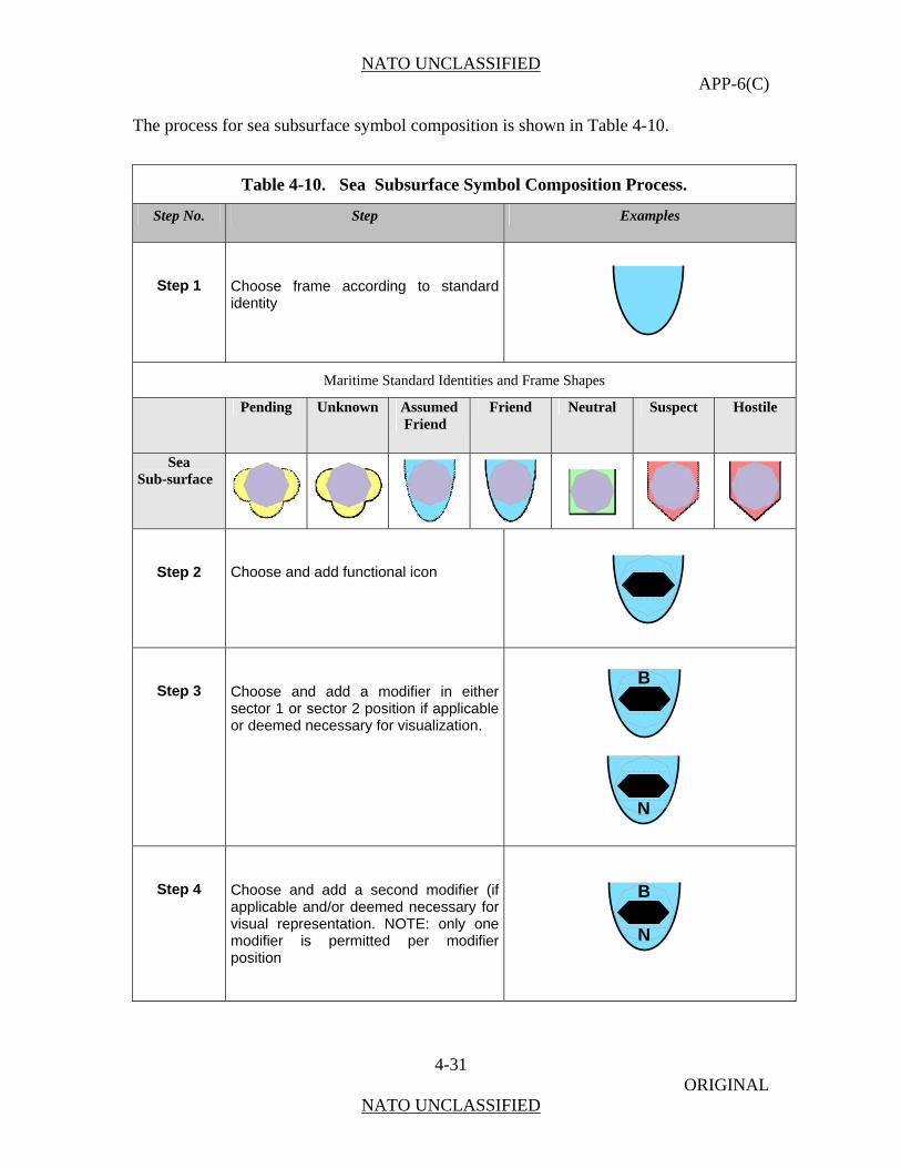
NATO UNCLASSIFIED APP-6(C)
4-31 ORIGINAL
NATO UNCLASSIFIED
The process for sea subsurface symbol composition is shown in Table 4-10.
ol Composition Process.
Table 4-10. Sea Subsurface Symb
Step No. Step Examples
Step 1 Choose frame according to standard identity
Maritime Standard Identities and Frame Shapes
Pending Unknown Assumed Friend
Friend Neutral Suspect Hostile
Sea Sub-surface
Step 2
Choose and add functional icon
Step 3 Choose and add a modifier in esector 1 or sector 2 position if applicor deemed necessary for visualizatio
ither able n.
Step
d a second modifier (if ed necessary for
visual representation. NOTE: only one modifier isposition
4 Choose and adapplicable and/or deem
permitted per modifier
B
N
B
N
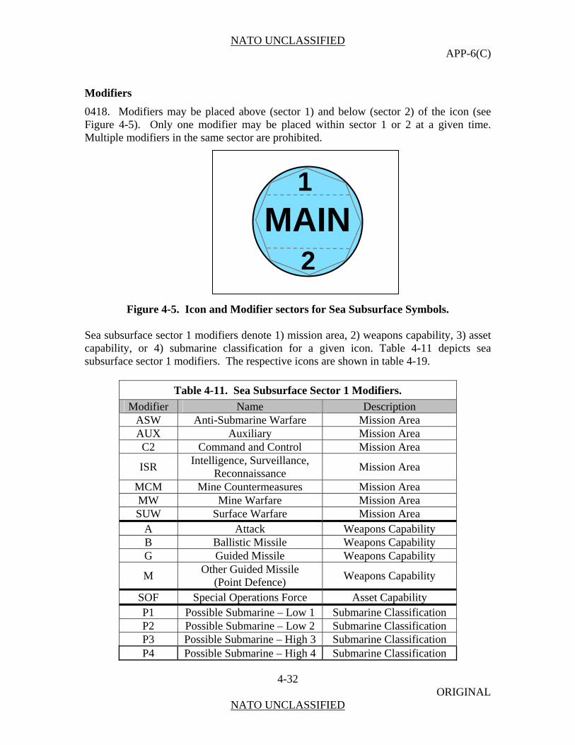
NATO UNCLASSIFIED APP-6(C)
4-32 ORIGINAL
NATO UNCLASSIFIED
Modifiers
0418. Modifie icon (see Figure 4-5). O iven time. M odifiers in the same r are prohibited.
ure 4-5. Icon and Modifier sectors for Sea Subsurface Symbols. Sea subsurface sector 1 modifiers denote 1) mission area, 2) weapons capability, 3) asset capability, or 4) submarine classification for a given icon. Table 4-11 depicts sea sub se e icons are shown in table 4-19.
Table 4-11. Sea Subsurface Sector 1 Modifiers.
rs may be placed above (sector 1) and below (sector 2) of thenly one modifier may be placed within sector 1 or 2 at a g
ultiple m secto
Fig
surface ctor 1 modifiers. The respectiv
Modifier Name Description ASW Anti-Submarine Warfare Mission Area AU ission Area X Auxiliary MC ssion Area 2 Command and Control Mi
ISReconnaissance
Mission Area R Intelligence, Surveillance,
MCM Mine Countermeasures Mission Area MW Mine Warfare Mission Area SUW Surface Warfare Mission Area
A Attack Weapons Capability B Ballistic Missile Weapons Capability G Guided Missile Weapons Capability
M Weapons Capability Other Guided Missile
(Point Defence) S Asset Capab y OF Special Operations Force ilitP bmarine – Low 1 Submarine Classification 1 Possible SuP2 Possible Submarine – Low 2 Submarine Classification P3 Possible Submarine – High 3 Submarine Classification P4 Possible Submarine – High 4 Submarine Classification
MAIN1
2

NATO UNCLASSIFIED APP-6(C)
4-33 ORIGINAL
NATO UNCLASSIFIED
PB Probable Submarine Submarine Classification CT Certain Submarine Submarine Classification
Sea subsurface sector 2 modifiers depict 1) ship propulsion or 2) unmanned underwater vehicle (UUV) control. Table 4-12 lists sea subsurface sector 2 modifiers. The respective icons are shown in table 4-20.
Table 4-12. Sea Subsurface Sector 2 Modifiers.
Modifier Name Description AI Air Independen Ship Propulsion t Propulsion D Diesel Prop Ship Propulsion ulsion D1 Diesel – T Ship Propulsion ype 1 D2 Diesel – Type 2 Ship Propulsion D3 Diesel – Type 3 Ship Propulsion N Nuclear Powered Ship Propulsion N1 Nuclear – Type 1 Ship Propulsion N2 Nuclear – Type 2 Ship Propulsion N3 Nuclear – Type 3 Ship Propulsion N4 Nuclear – Type 4 Ship Propulsion N5 Nuclear – Type 5 Ship Propulsion N6 Nuclear – Type 6 Ship Propulsion N7 Nuclear – Type 7 Ship Propulsion
AUT rol Autonomous Control UUV ContRP Rem loted UUV otely Pi Control
EXP Expendable UUV Control
Amplifiers
0419. On t ctical a display nveyed by the symbol vi p ur coding. be, however, additional ying i e conveye means, but by written (alphanumerical) i information yed either in secondary al screen, a m s the operator to a constant shift of focus and will not be considered further in this text, or by use of amplifiers in orm of sym
The purpose of the amp section of additional alphanumerica ov apabilities, etc. Figure hows s with a e placement of the ampl the e o
he ta display, information about ed object is coa frame shaa r
e, icon/letter and colonform not b
There may nd va ation that can d by graphical
nformation. This may be displaethod that forceinformation fields outside the tactic
the f bol labels.
lifiers described in thisl information on identity, m
is to standardize the displayement and location, c
4-6 sifier is
the placement of amplifierme regardless of frame sha
symbol frame. Thndard identity. sa p r sta

NATO UNCLASSIFIED APP-6(C)
4-34 ORIGINAL
NATO UNCLASSIFIED
aritime dom
set of amplifiers for sea subsurface symnd time, shall be displayed in the five standard amplifier scheme fields (see chapter. 1,
Figure 1.4) to the ri on of the standard information fields differs from tho for symbols in land ins.
In the defaul de, th the us e and call up for display the information ecessary. A user must be enabled to ess the am screen clu up again as considered appropriate to the tactical situation.
The speed leader is a dynami picts the spe of movement (course) and originates from object. T speed leader corresponds to the speed of t
rface symbol amplifier fields.
M ain symbol amplifiers require a reduced amount of information to be displayed in one position relative to the symbol as compared to Land Symbols (see Chapter 3). Maritime amplifiers shall be placed to the immediate right of the symbol as opposed to separate positions surrounding it.
Aa
bols, including object name, position, speed,
ght of the symbol as given in Figure 4-6. The positise used and air doma
t mo e amplifier is not shown. It is er’s task to definconsidered to be n dditionally, the
suppr plifier to reduce tter and call it
c amplifier that de ed and direction the centre of the he length of the
he object.
Figure 4-6. Sea Subsu
Table 4-13 provides the possibilities of information display for military and non-military sea subsurface symbols by amplifiers.
1
Speed Leader
2
3
4
5
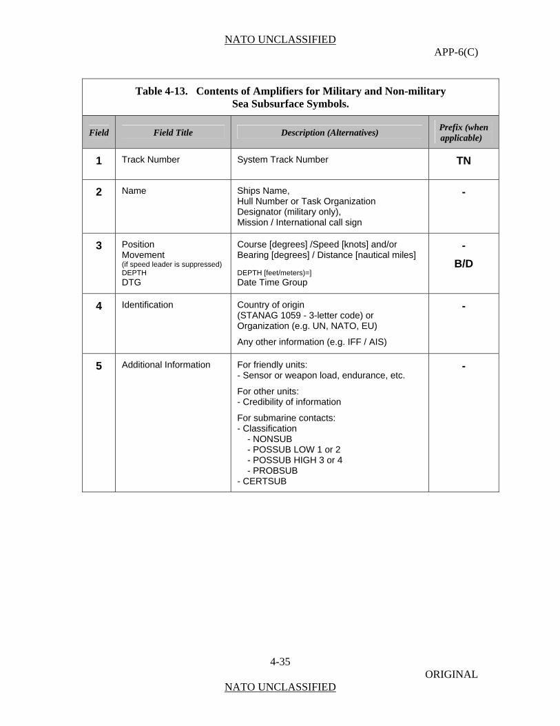
NATO UNCLASSIFIED APP-6(C)
4-35 ORIGINAL
NATO UNCLASSIFIED
Table 4-13. Contents of Amplifiers for Military and Non-military Sea Subsurface Symbols.
Field Field Title Description (Alternatives) Prefix (when applicable)
1 Track Number System Track Number TN
2 Name Ships Name, Hull Number or Task Organization Designator (military only), Mission / International call sign
-
3 Position Course [degreMovement (if speed leader is suppressed) DEPTH DTG
Bearing [degrees] / Distance [nautical miles] DEPTH [feet/meters)=] Date Time Group
B/D
es] /Speed [knots] and/or -
4
Identification Country of origin (STANAG 1059 - 3-letter code) or Organization (e.g. UN, NATO, EU)
Any other information (e.g. IFF / AIS)
-
5 Additional Information For friendly units: - Sensor or weapon load, endurance, e
For other units: - Credibility of information
For submarine contacts: - Classification
- NONSUB - POSSUB LOW 1 or 2 - POSSUB HIGH 3 or 4 - PROBSUB
- CERTSUB
-
tc.
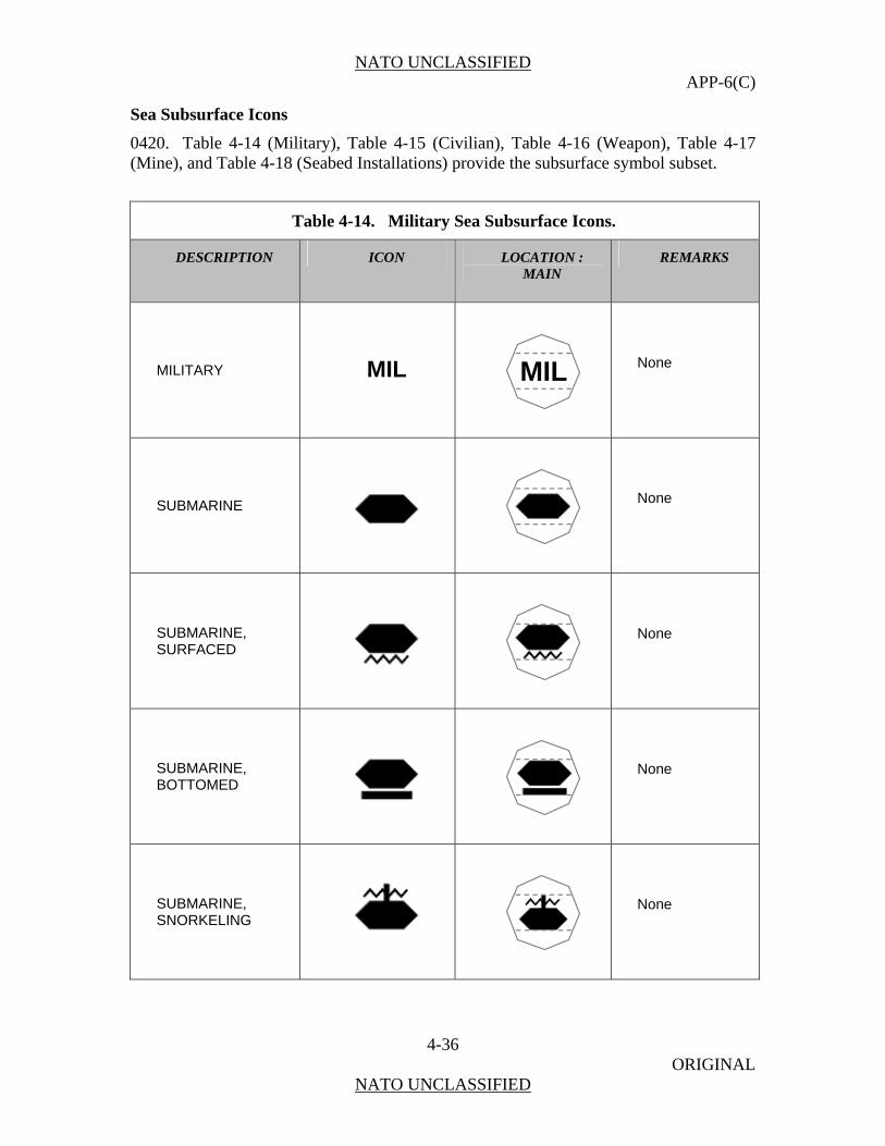
NATO UNCLASSIFIED APP-6(C)
4-36 ORIGINAL
NATO UNCLASSIFIED
Sea Subsurface Icons
0420. Tab 4-17 (Mine), and Table 4-18 (Seabed I surface symbol subset.
le 4-14 (Military), Table 4-15 (Civilian), Table 4-16 (Weapon), Tablenstallations) provide the sub
Table 4-14. Military Sea Subsurface Icons.
DESCRIPTION ICON LOCATION : MAIN
REMARKS
MILITARY MIL
MIL
None
SUBMARINE
None
SUBMARINE, SURFACED
None
SUBMARINE, BOTTOMED
None
SUBMARINE, SNORKELING
None

NATO UNCLASSIFIED APP-6(C)
4-37 ORIGINAL
NATO UNCLASSIFIED
Table 4-14. Military Sea Subsurface Icons.
DESCRIPTION ICON LOCATION : MAIN
REMARKS
OTSUBMERSIBLE
HER
None
AUTONOMOUS UNDERWATER VEHICLE/ UNMANNED UNDERWATER VEHICLE (AUV/UUV)
None
NON-SUBMARINE
NON SUB
NONSUB
None
DIVER, MILITARY
None

NATO UNCLASSIFIED APP-6(C)
4-38 ORIGINAL
NATO UNCLASSIFIED
Table 4-15. N ilitary Sea S ons. on-M ubsurface Ic
DESCRIPTION ICON LOCATION : MAIN REMARKS
CIVILIAN
CIV
CIV
None
SUBCIVI
MERSIBLE, LIAN
None
AUTONOMOUS UNDERWATER VEHUNMAUNDERWATER VEHICLE (AUV/UUV), CIVILIAN
ICLE/ NNED
None
DIVER, CIVILIAN
None
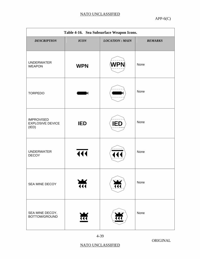
NATO UNCLASSIFIED APP-6(C)
4-39 ORIGINAL
NATO UNCLASSIFIED
Table 4-16. Sea Subsurface Weapon Icons.
DESCRIPTION ICON LOCATION : MAIN REMARKS
UNDERWATER W WEAPON
PN
WPN
None
TORPEDO
None
IMPROVISED EXPLOSIVE DEV(IED)
ICE IED IED
None
UNDERWATER DECOY
None
SEA MINE DECOY
None
SEA MINE DECOY, BOTTOM/GROUND
None
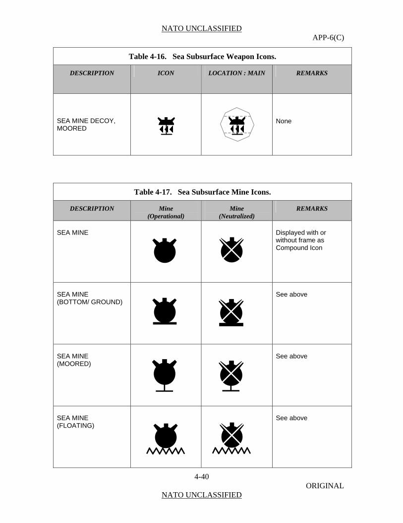
NATO UNCLASSIFIED APP-6(C)
4-40 ORIGINAL
NATO UNCLASSIFIED
Table 4-16. Sea Subsurface Weapon Icons.
DESCRIPTION ICON LOCATION : MAIN REMARKS
SEA MINE DECOY, MOORED
None
Table 4-17. Sea Subsurface Mine Icons.
DESCRIPTION Mine (Operational)
Mine (Neutralized)
REMARKS
SEA MINE
isplayed with or without frame as
d Icon
D
Compoun
SEA MINE ND) (BOTTOM/ GROU
See above
SEA MINE (MOORED)
See above
SEA MINE (FLOATING)
See above

NATO UNCLASSIFIED APP-6(C)
4-41 ORIGINAL
NATO UNCLASSIFIED
SEA MINE (IN OTHER POSITION)
See above
SEA MINE (RISING)
See above
UNEXPLODED EXPLOSIVE ORDNANCE
UXO
Displayed with frame
Table 4-18. Sea Subsurface Installations.
DESCRIPTION ICON LOCATION : MAIN REMARKS
SEABED INSTALLATION, MAN-MADE, MILITARY
None
SEABED INSTALLATION, MAN-MADE, NON-MILITARY
None

NATO UNCLASSIFIED APP-6(C)
4-42 ORIGINAL
NATO UNCLASSIFIED
Sea Subsu
0421. Table 4-19 list
rface Modifiers
s sea subsurface sector 1 modifiers and illustrates their placement within the bounding octagon.
Table 4-19. Sea Subsurface Sector 1 Modifiers.
FUNCTION MODIFIER LOCATION:
REMARKS
ANTISUBMARINE WARFARE
ASW
ASW
None
AUXILIARY
AUX AUX
None
COMMAND AND CONTROL
C2
C2
None
ITELLIGENCE, SURVEILLANCE, RECONNAISSANCE ISR
ISR
None
MINE COUNTERMEASURES
MCM
MCM
None

NATO UNCLASSIFIED APP-6(C)
4-43 ORIGINAL
NATO UNCLASSIFIED
Table 4-19. Sea Subsurface Sector 1 Modifiers.
FUNCTION MODIFIER LOCATION:
REMARKS
MINE WARFARE
MW MW
None
SURFACE WARFARE
SUW SUW
None
ATTACK
A
A
None
BALLISTIC MISSILE
B
B
None
GUIDED MISSILE
G G
None
OTHER GUIDED MISSILES (POINT DEFENCE)
M M
None
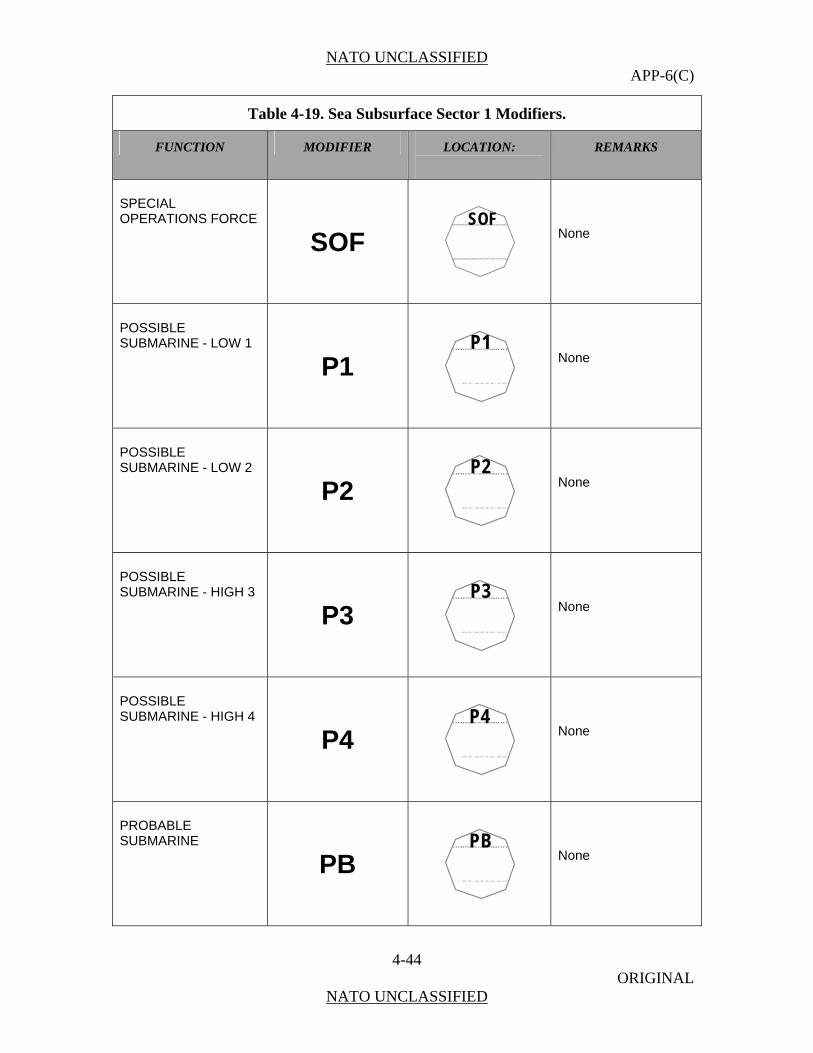
NATO UNCLASSIFIED APP-6(C)
4-44 ORIGINAL
NATO UNCLASSIFIED
Table 4-19. Sea Subsurface Sector 1 Modifiers.
FUNCTION MODIFIER LOCATION:
REMARKS
SPECIAL OPERATIONS FORCE
SOF
SOF
None
POSSIBLE SUBMARINE - LOW 1
P1 P1
None
POSSIBLE SUBMARINE - LOW 2
P2 P2
None
POSSIBLE SUBMARINE - HIGH 3
P3 P3
None
POSSIBLE SUBMARINE - HIGH 4
P4 P4
None
PROBABLE SUBMARINE
PB PB
None
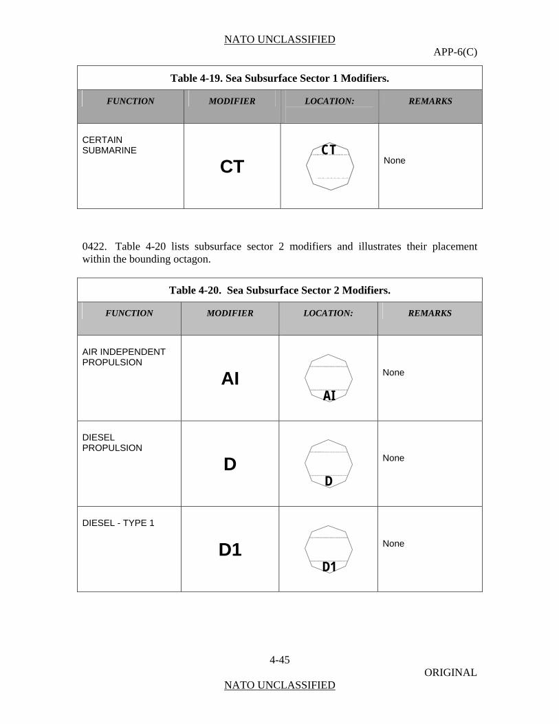
NATO UNCLASSIFIED APP-6(C)
4-45 ORIGINAL
NATO UNCLASSIFIED
Table 4-19. Sea Subsurface Sector 1 Modifiers.
FUNCTION MODIFIER LOCATION:
REMARKS
CERTAIN SUBMARINE
CT CT
None
0422. Table 4-20 lists subsu ector 2 modifiers and illust eir placement within the bounding octagon.
Table 4-20. Sea Subsurface Sector 2 Modifiers.
rface s rates th
FUNCTION MODIFIER LOCATION:
REMARKS
AIR INDEPENDENT PROPULSION
AI
AI
None
DIESEL PROPULSION
D
D
None
DIESEL - TYPE 1
D1
D1
None
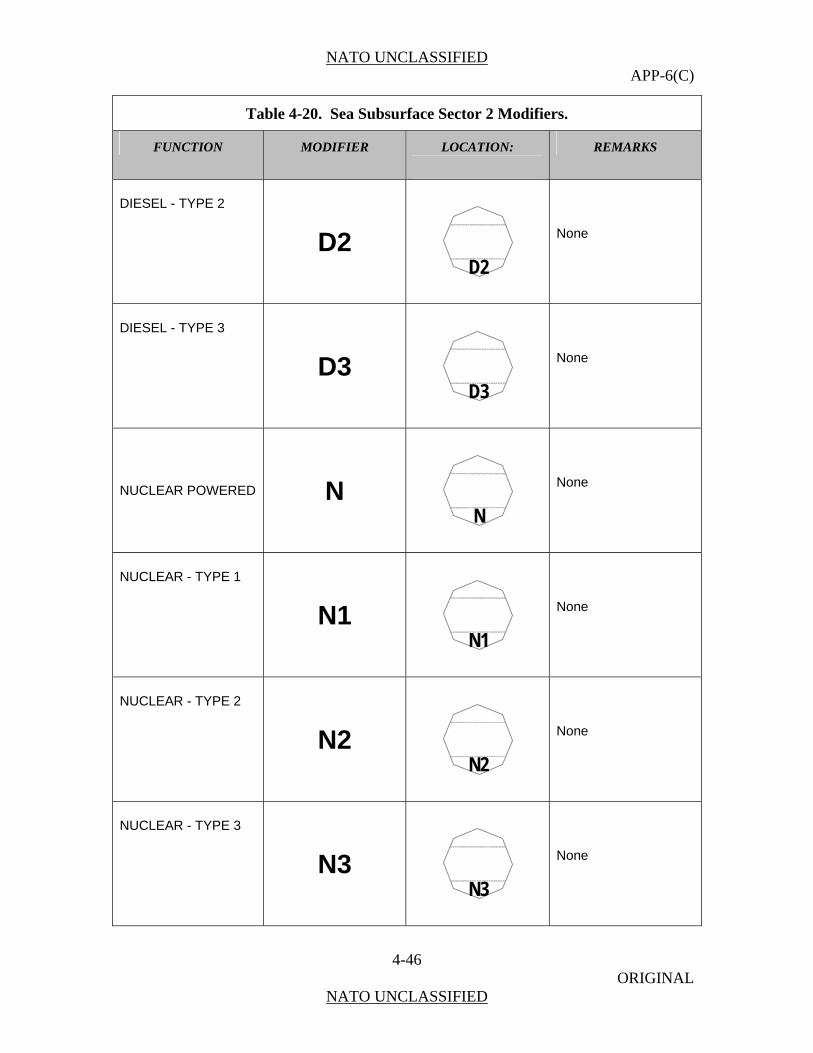
NATO UNCLASSIFIED APP-6(C)
4-46 ORIGINAL
NATO UNCLASSIFIED
Table 4-20. Sea Subsurface Sector 2 Modifiers.
FUNCTION MODIFIER LOCATION:
REMARKS
DIESEL - TYPE 2
D2
D2
None
DIESEL - TYPE 3
D3
D3
None
NUCLEAR POWERED N
N
None
NUCLEAR - TYPE 1
N1
N1
None
NUCLEAR - TYPE 2
N2
N2
None
NUCLEAR - TYPE 3
N3
N3
None

NATO UNCLASSIFIED APP-6(C)
4-47 ORIGINAL
NATO UNCLASSIFIED
Table 4-20. Sea Subsurface Sector 2 Modifiers.
FUNCTION MODIFIER LOCATION:
REMARKS
NUCLEAR - TYPE 4
N4
N4
None
NUCLEAR - TYPE 5
N5
N5
None
NUCLEAR - TYPE 6
N6
N6
None
NUCLEAR - TYPE 7
N7
N7
None
AUTONOMOUS CONTROL AUT
AUT
None
REMOTELY PILOTED RP
RP
None
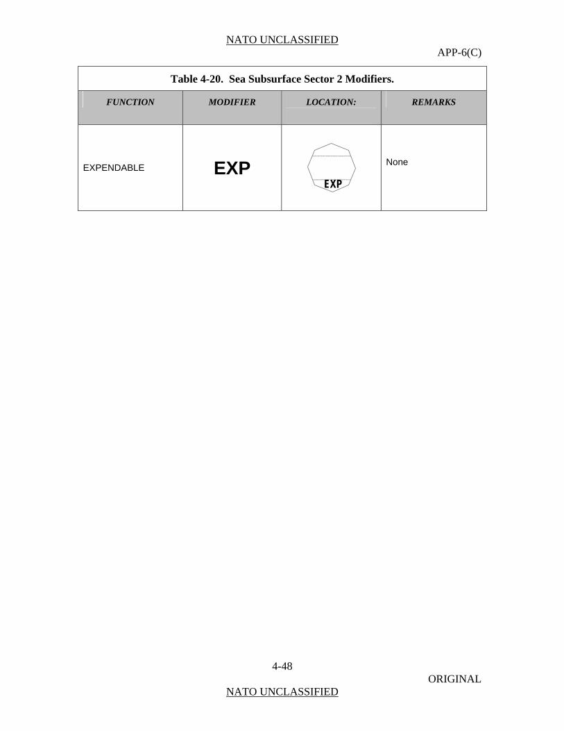
NATO UNCLASSIFIED APP-6(C)
4-48 ORIGINAL
NATO UNCLASSIFIED
Table 4-20. Sea Subsurface Sector 2 Modifiers.
FUNCTION MODIFIER LOCATION: REMARKS
EXPENDABLE EXP
EXP
None
NATO UNCLASSIFIED APP-6(C)
5-1 ORIGINAL
NATO UNCLASSIFIED
CHAPTER 5
SPACE SYMBOLS
Scope
0501. This chapter covers symbols for space assets, related activities and other relevant objects (debris) within earth orbit. Space-related ground installations are covered in Chapter 3 “Land Symbols”.
Characteristics of Symbols for Space Operations
0502. Security and military operations are dependent on space capabilities for command and control (C2), communications, situation awareness, and intelligence, surveillance and reconnaissance (ISR). Because of meteorological satellites, forces no longer have to wonder how weather will impact future operations. The global positioning system (GPS) provides precise position, navigation and timing information to expeditionary and mobile forces. Additionally, satellites provide missile warning and tracking information. Space systems enable friendly force tracking for shared situational awareness, enable precision engagement for time sensitive targets, and shorten the joint air tasking cycle. The persistence (always on orbit), perspective (high altitude), penetration (no over flight restrictions), and presence (ability to provide combat support without being physically located with forward forces) of space systems provide forces beyond line of sight secure communications. In order to depict in near-real time large areas with fast moving space users manoeuvring within all three dimensions, specific requirements for the space picture production have to be met:
a. The picture has to be updated in near real-time.
b. Vectors have to be provided in order to help to anticipate movement of own, neutral and hostile objects.
c. Wherever known, relevant data like “type”, “mission”, “operator”, “capabilities” etc. have to be affiliated to the objects without cluttering the display.
d. Objects may overlap on the display but must still be recognisable to controllers.
e. Depending on the scenario, the display may contain a multitude of moving objects (debris).

NATO UNCLASSIFIED APP-6(C)
5-2 ORIGINAL
NATO UNCLASSIFIED
SECTION I - BUILDING SPACE SYMBOLS
General
0503. This section establishes a single standard for developing space symbols. It includes a variety of space related icons, modifiers, and amplifiers for building symbols. However, no attempt to depict all possible space symbols has been made. Rather, a standard method for constructing these symbols is presented. Once the user is familiar with the prescribed system, a symbol for any conceivable object can be created using the logical sequence provided in this chapter. The symbols shown in this chapter are adequate for depicting all standard identities. When representing not yet defined objects, the most appropriate symbol combination contained herein shall be selected. Any symbols, or combinations and modifications of symbols that differ from those laid down in this publication should be avoided. If, after searching icons and modifiers given in this publication, it is necessary to create a new symbol, the symbol shall be explained in an accompanying legend. Automated systems may have difficulty in passing non-standard symbols.
Composition of Space Symbols
0504. A space symbol is composed of a frame, colour (fill), functional icon (main icon), and modifiers (secondary icons) (figure 5-1).
Figure 5-1. Space Symbol Composition. See table 5-1 for the steps used to build space symbols.

NATO UNCLASSIFIED APP-6(C)
5-3 ORIGINAL
NATO UNCLASSIFIED
Table 5-1. Building Unit Symbols.
Step # Step Example
Step 1. Choose the frame according to standard identity.
Affiliations and Frame Shapes
Affiliation Pending Unknown Assumed Friend
Friend Neutral Suspect Hostile
Frame
Step 2. Choose and add main sector icon.
Step 3. Choose and add a modifier in either sector 1 or sector 2 if applicable or deemed necessary for visualization.
Step 4. Choose and add a modifier in either sector 1 or sector 2 if applicable or deemed necessary for visualization. NOTE: Only one modifier is permitted per modifier position.

NATO UNCLASSIFIED APP-6(C)
5-4 ORIGINAL
NATO UNCLASSIFIED
Amplifier Fields
0505. On the tactical display, information about a displayed object is conveyed by the symbol via frame shape, icon/letter and colour coding. There may be, however, additional information that cannot be conveyed by graphical means, but by written (alphanumerical) information only.
0506. This information can be displayed either in secondary information fields outside the tactical screen, a method that forces the operator to a constant shift of focus and will not be considered further in this text, or by use of amplifier fields.
0507. The purpose of the amplifier fields described in this section is to standardize the display of additional alphanumerical information, i.e. on identity, location and movement, capabilities. Figure 5-2 shows the placement of amplifier fields around a space symbol frame. The placement of the label is the same regardless of frame shape or affiliation.
0508. Space amplifier fields are to be displayed in one position relative to the symbol, its right side and not in different and separate positions all around it. Track number, name, position, and nation are considered essential information and displayed in fields 1 through 5 to the right of the symbol.
0509. In the default mode, the label is not shown. It is the user’s task to define and call up for display the information considered to be necessary. Additionally, the user must be enabled to suppress the filled and displayed label to reduce screen clutter and call it up again as considered appropriate to the tactical situation. Table 5-2 lists the contents and descriptions for the space amplifier fields.
1
2
3
4
5
Figure 5-2. Symbol Amplifier Fields.
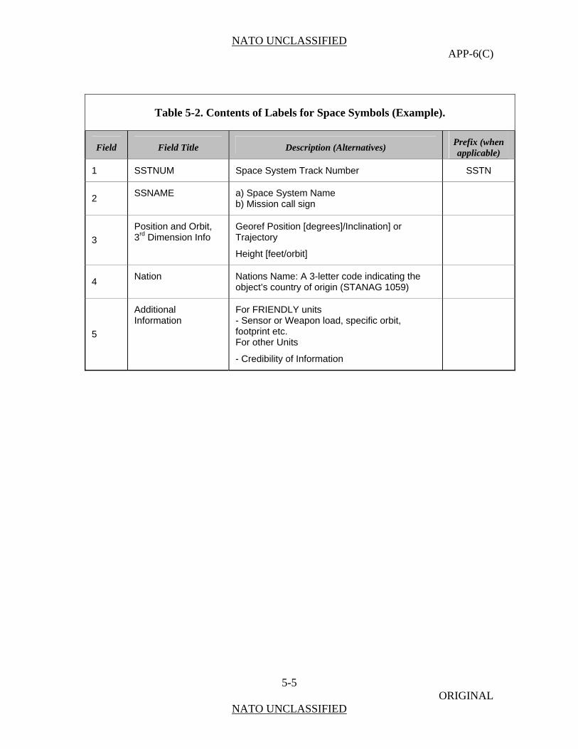
NATO UNCLASSIFIED APP-6(C)
5-5 ORIGINAL
NATO UNCLASSIFIED
Table 5-2. Contents of Labels for Space Symbols (Example).
Field Field Title Description (Alternatives) Prefix (when applicable)
1 SSTNUM Space System Track Number SSTN
2 SSNAME a) Space System Name
b) Mission call sign
3
Position and Orbit, 3rd Dimension Info
Georef Position [degrees]/Inclination] or Trajectory
Height [feet/orbit]
4 Nation Nations Name: A 3-letter code indicating the
object’s country of origin (STANAG 1059)
5
Additional Information
For FRIENDLY units - Sensor or Weapon load, specific orbit, footprint etc. For other Units
- Credibility of Information
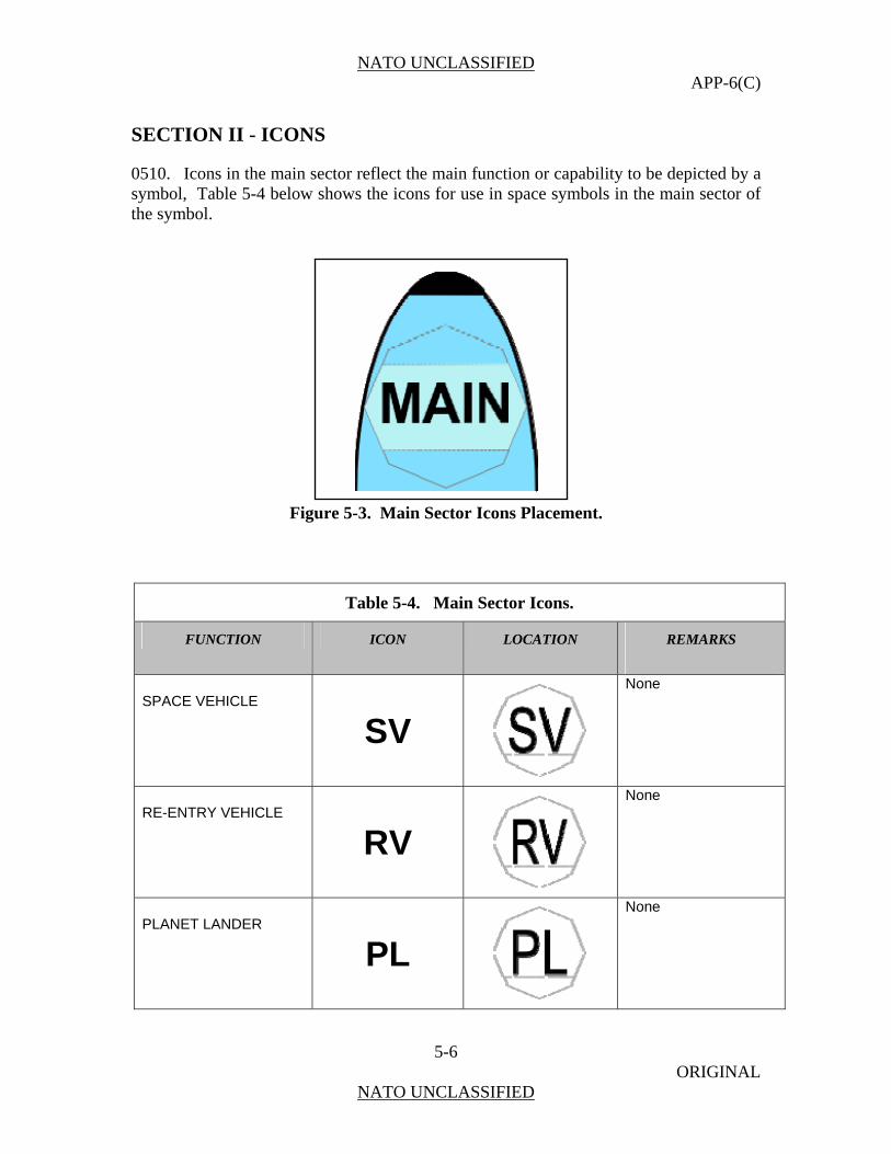
NATO UNCLASSIFIED APP-6(C)
5-6 ORIGINAL
NATO UNCLASSIFIED
SECTION II - ICONS
0510. Icons in the main sector reflect the main function or capability to be depicted by a symbol, Table 5-4 below shows the icons for use in space symbols in the main sector of the symbol.
Figure 5-3. Main Sector Icons Placement.
Table 5-4. Main Sector Icons.
FUNCTION ICON LOCATION REMARKS
SPACE VEHICLE
SV
None
RE-ENTRY VEHICLE
RV
None
PLANET LANDER
PL
None

NATO UNCLASSIFIED APP-6(C)
5-7 ORIGINAL
NATO UNCLASSIFIED
Table 5-4. Main Sector Icons.
FUNCTION ICON LOCATION REMARKS
ORBITER SHUTTLE MILITARY
None
ORBITER SHUTTLE CIVILIAN
None
MILITARY CAPSULE
None
CIVILIAN CAPSULE
None
SATELLITE, GENERAL
SAT
None
MILITARY SATELLITE
None
CIVIL SATELLITE
Main
None

NATO UNCLASSIFIED APP-6(C)
5-8 ORIGINAL
NATO UNCLASSIFIED
Table 5-4. Main Sector Icons.
FUNCTION ICON LOCATION REMARKS
ANTI-SATELLITE WEAPON
None
ASTRONOMICAL SATELLITE MILITARY
None
ASTRONOMICAL SATELLITE CIVIL
None
BIOSATELLITE MILITARY
None
BIOSATELLITE CIVIL
None
COMMUNICATIONS SATELLITE MILITARY
None
COMMUNICATIONS SATELLITE CIVIL
Main
None
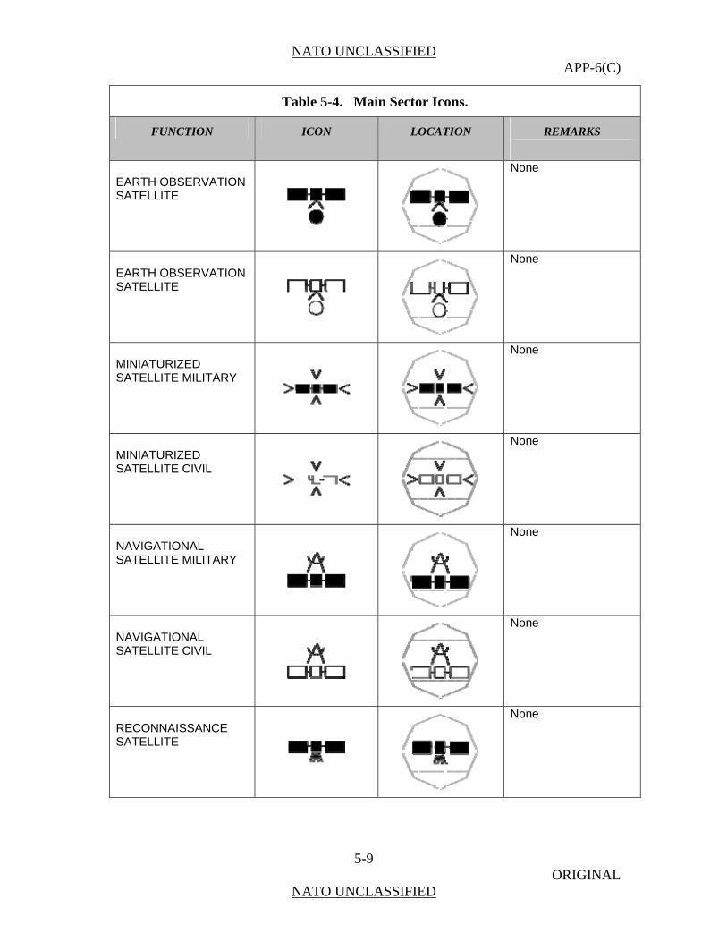
NATO UNCLASSIFIED APP-6(C)
5-9 ORIGINAL
NATO UNCLASSIFIED
Table 5-4. Main Sector Icons.
FUNCTION ICON LOCATION REMARKS
EARTH OBSERVATION SATELLITE
None
EARTH OBSERVATION SATELLITE
None
MINIATURIZED SATELLITE MILITARY
None
MINIATURIZED SATELLITE CIVIL
None
NAVIGATIONAL SATELLITE MILITARY
None
NAVIGATIONAL SATELLITE CIVIL
None
RECONNAISSANCE SATELLITE
None

NATO UNCLASSIFIED APP-6(C)
5-10 ORIGINAL
NATO UNCLASSIFIED
Table 5-4. Main Sector Icons.
FUNCTION ICON LOCATION REMARKS
SPACE STATION MILITARY
None
SPACE STATION CIVIL
None
TETHER SATELLITE MILITARY
None
TETHER SATELLITE CIVIL
None
WEATHER SATELLITE MILITARY
None
WEATHER SATELLITE CIVIL
None

NATO UNCLASSIFIED APP-6(C)
5-11 ORIGINAL
NATO UNCLASSIFIED
SECTION III – SECTOR MODIFIERS
0511. Modifiers in sector 1 (Figure 5-4) and sector 2 (Figure 5-5) show modifying information. Specifically, sector 1 space modifiers denote orbit; whereas, sector 2 space modifiers denote sensors. Tables 5-5 and 5-6 show the icons for use in space symbols in sector 1 and 2.
Table 5-5. Sector 1 Modifier (Type of Orbit).
FUNCTION ICON LOCATION REMARKS
LOW EARTH ORBIT (LEO)
LEO
None
MEDIUM EARTH ORBIT (MEO)
MEO
None
HIGH EARTH ORBIT (HEO)
HEO
None
Figure 5-4. Sector 1 Modifier Placement.
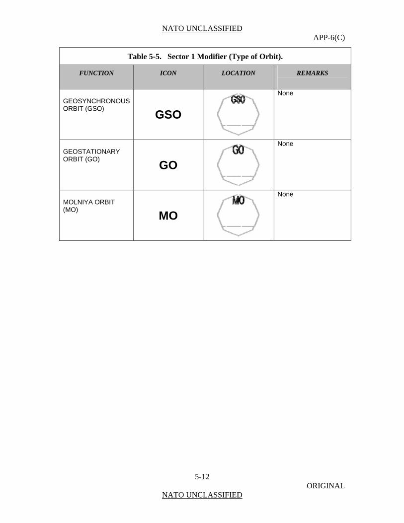
NATO UNCLASSIFIED APP-6(C)
5-12 ORIGINAL
NATO UNCLASSIFIED
Table 5-5. Sector 1 Modifier (Type of Orbit).
FUNCTION ICON LOCATION REMARKS
GEOSYNCHRONOUS ORBIT (GSO)
GSO
None
GEOSTATIONARY ORBIT (GO)
GO
None
MOLNIYA ORBIT (MO)
MO
None

NATO UNCLASSIFIED APP-6(C)
5-13 ORIGINAL
NATO UNCLASSIFIED
Table 5-6. Sector 2 Modifiers (Type of Sensors).
FUNCTION ICON LOCATION REMARKS
OPTICAL
O
Only used with satellite.
INFRA-RED
IR
Only used with satellite.
RADAR
R
Only used with satellite.
SIGINT
SI
Only used with satellite.
Figure 5-5. Sector 2 Modifier Placement.
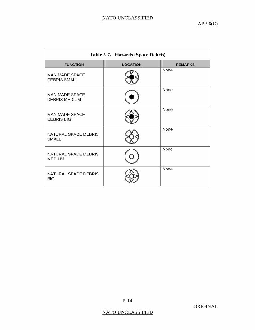
NATO UNCLASSIFIED APP-6(C)
5-14 ORIGINAL
NATO UNCLASSIFIED
Table 5-7. Hazards (Space Debris)
FUNCTION LOCATION REMARKS
MAN MADE SPACE DEBRIS SMALL
None
MAN MADE SPACE DEBRIS MEDIUM
None
MAN MADE SPACE DEBRIS BIG
None
NATURAL SPACE DEBRIS SMALL
None
NATURAL SPACE DEBRIS MEDIUM
None
NATURAL SPACE DEBRIS BIG
None
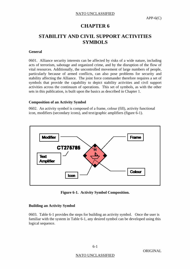
NATO UNCLASSIFIED APP-6(C)
6-1 ORIGINAL
NATO UNCLASSIFIED
CHAPTER 6
STABILITY AND CIVIL SUPPORT ACTIVITIES SYMBOLS
General 0601. Alliance security interests can be affected by risks of a wide nature, including acts of terrorism, sabotage and organized crime, and by the disruption of the flow of vital resources. Additionally, the uncontrolled movement of large numbers of people, particularly because of armed conflicts, can also pose problems for security and stability affecting the Alliance. The joint force commander therefore requires a set of symbols that provide the capability to depict stability activities and civil support activities across the continuum of operations. This set of symbols, as with the other sets in this publication, is built upon the basics as described in Chapter 1.
Composition of an Activity Symbol
0602. An activity symbol is composed of a frame, colour (fill), activity functional icon, modifiers (secondary icons), and text/graphic amplifiers (figure 6-1).
Figure 6-1. Activity Symbol Composition. Building an Activity Symbol 0603. Table 6-1 provides the steps for building an activity symbol. Once the user is familiar with the system in Table 6-1, any desired symbol can be developed using this logical sequence.

NATO UNCLASSIFIED APP-6(C)
6-2 ORIGINAL
NATO UNCLASSIFIED
Table 6-1. Building An Activity, Location, or Non-military Organization Symbol.
Step # Step Example
Step 1. Choose the frame according to standard identity.
Activity Symbol Frame Shapes and Affiliation
STANDARDIDENTITY
FRAME
PENDINGFRIENDLY HOSTILE NEUTRAL UNKNOWNASSUMED
FRIENDSUSPECT
STANDARDIDENTITY
FRAME
PENDINGFRIENDLY HOSTILE NEUTRAL UNKNOWNASSUMED
FRIENDSUSPECT
Steps 2. Choose and add main sector icon.
Step 3. Choose and add a modifier in either sector 1 or sector 2 if applicable or deemed necessary for visualization.
Step 4. Choose and add a modifier in either sector 1 or sector 2 if applicable or deemed necessary for visualization. NOTE: Only one modifier is permitted per modifier position.
There are no specific sector 2 modifiers at this time.
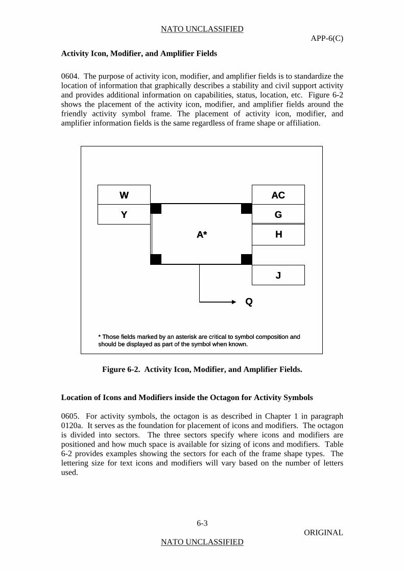
NATO UNCLASSIFIED APP-6(C)
6-3 ORIGINAL
NATO UNCLASSIFIED
Activity Icon, Modifier, and Amplifier Fields
0604. The purpose of activity icon, modifier, and amplifier fields is to standardize the location of information that graphically describes a stability and civil support activity and provides additional information on capabilities, status, location, etc. Figure 6-2 shows the placement of the activity icon, modifier, and amplifier fields around the friendly activity symbol frame. The placement of activity icon, modifier, and amplifier information fields is the same regardless of frame shape or affiliation.
W
Y
AC
G
H
J
Q
A*
* Those fields marked by an asterisk are critical to symbol composition and should be displayed as part of the symbol when known.
W
Y
AC
G
H
J
Q
A*
* Those fields marked by an asterisk are critical to symbol composition and should be displayed as part of the symbol when known.
Figure 6-2. Activity Icon, Modifier, and Amplifier Fields.
Location of Icons and Modifiers inside the Octagon for Activity Symbols 0605. For activity symbols, the octagon is as described in Chapter 1 in paragraph 0120a. It serves as the foundation for placement of icons and modifiers. The octagon is divided into sectors. The three sectors specify where icons and modifiers are positioned and how much space is available for sizing of icons and modifiers. Table 6-2 provides examples showing the sectors for each of the frame shape types. The lettering size for text icons and modifiers will vary based on the number of letters used.
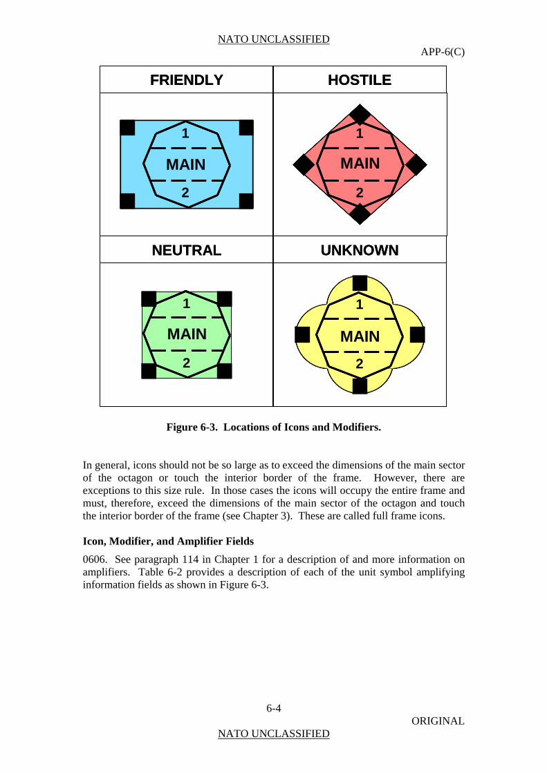
NATO UNCLASSIFIED APP-6(C)
6-4 ORIGINAL
NATO UNCLASSIFIED
FRIENDLY HOSTILE
NEUTRAL UNKNOWN
MAIN
1
2
MAIN
1
2
MAIN
1
2
MAIN
1
2
FRIENDLY HOSTILE
NEUTRAL UNKNOWN
MAIN
1
2
MAIN
1
2
MAIN
1
2
MAIN
1
2
MAIN
1
2
MAIN
1
2
MAIN
1
2
MAIN
1
2
MAIN
1
2
MAIN
1
2
MAIN
1
2
MAIN
1
2
MAIN
1
2
MAIN
1
2
MAIN
1
2
Figure 6-3. Locations of Icons and Modifiers.
In general, icons should not be so large as to exceed the dimensions of the main sector of the octagon or touch the interior border of the frame. However, there are exceptions to this size rule. In those cases the icons will occupy the entire frame and must, therefore, exceed the dimensions of the main sector of the octagon and touch the interior border of the frame (see Chapter 3). These are called full frame icons. Icon, Modifier, and Amplifier Fields
0606. See paragraph 114 in Chapter 1 for a description of and more information on amplifiers. Table 6-2 provides a description of each of the unit symbol amplifying information fields as shown in Figure 6-3.
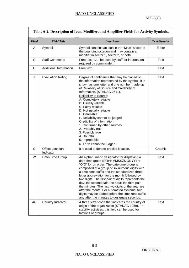
NATO UNCLASSIFIED APP-6(C)
6-5 ORIGINAL
NATO UNCLASSIFIED
Table 6-2. Description of Icon, Modifier, and Amplifier Fields for Activity Symbols.
Field Field Title Description Text/Graphic
A Symbol Symbol contains an icon in the “Main” sector of the bounding octagon and may contain a modifier in sector 1, sector 2, or both.
Either
G Staff Comments Free text. Can be used by staff for information required by commander.
Text
H Additional Information Free text. Text
J Evaluation Rating Degree of confidence that may be placed on the information represented by the symbol. It is shown as one letter and one number made up of Reliability of Source and Credibility of Information. (STANAG 2511). Reliability of Source: A. Completely reliable B. Usually reliable C. Fairly reliable D. Not usually reliable E. Unreliable F. Reliability cannot be judged. Credibility of Information: 1. Confirmed by other sources 2. Probably true 3. Possibly true 4. Doubtful 5. Improbable 6. Truth cannot be judged.
Text
Q Offset Location Indicator
It is used to denote precise location. Graphic
W Date-Time Group An alphanumeric designator for displaying a date-time group (DDHHMMSSZMONYY) or “O/O” for on order. The date-time group is composed of a group of six numeric digits with a time zone suffix and the standardized three-letter abbreviation for the month followed by two digits. The first pair of digits represents the day; the second pair, the hour; the third pair, the minutes. The last two digits of the year are after the month. For automated systems, two digits may be added before the time zone suffix and after the minutes to designate seconds.
Text
AC Country Indicator A three-letter code that indicates the country of origin of the organization (STANAG 1059). In stability activities, this field can be used for factions or groups.
Text
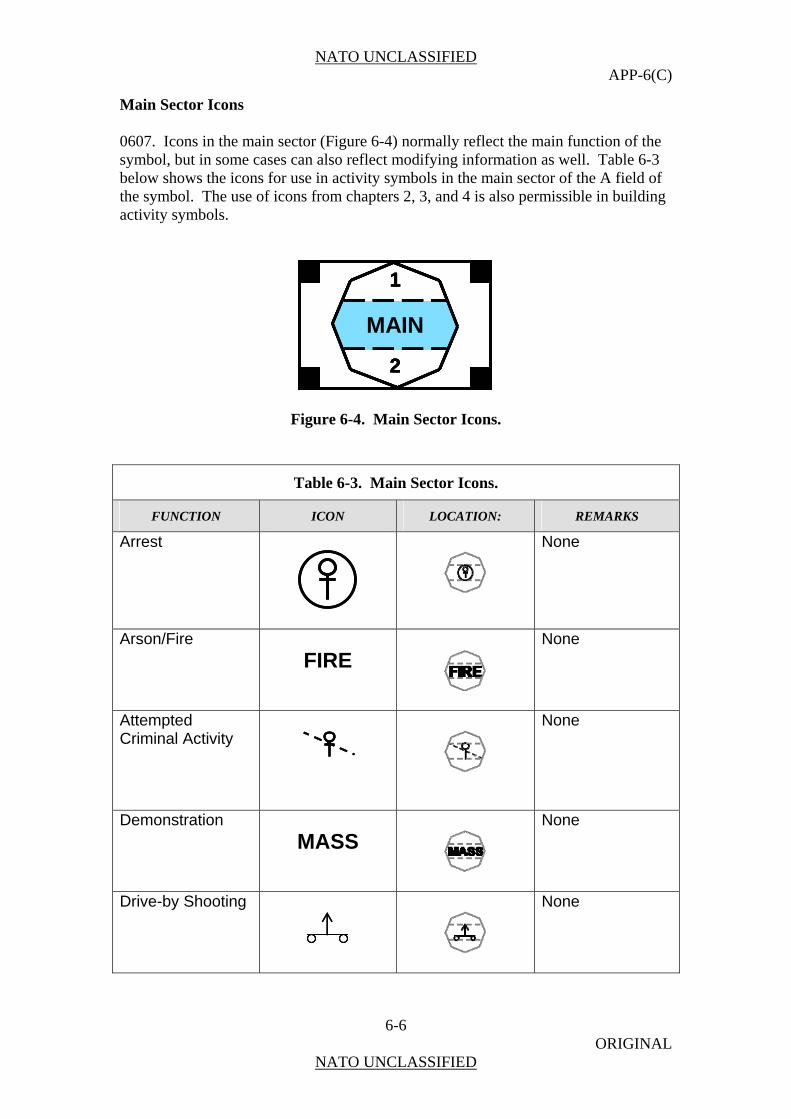
NATO UNCLASSIFIED APP-6(C)
6-6 ORIGINAL
NATO UNCLASSIFIED
Main Sector Icons 0607. Icons in the main sector (Figure 6-4) normally reflect the main function of the symbol, but in some cases can also reflect modifying information as well. Table 6-3 below shows the icons for use in activity symbols in the main sector of the A field of the symbol. The use of icons from chapters 2, 3, and 4 is also permissible in building activity symbols.
MAIN
1
2
MAIN
1
2
MAIN
1
2
MAIN
1
2
Figure 6-4. Main Sector Icons.
Table 6-3. Main Sector Icons.
FUNCTION ICON LOCATION: REMARKS
Arrest
None
Arson/Fire
FIRE
None
Attempted Criminal Activity
None
Demonstration
MASS
None
Drive-by Shooting
None
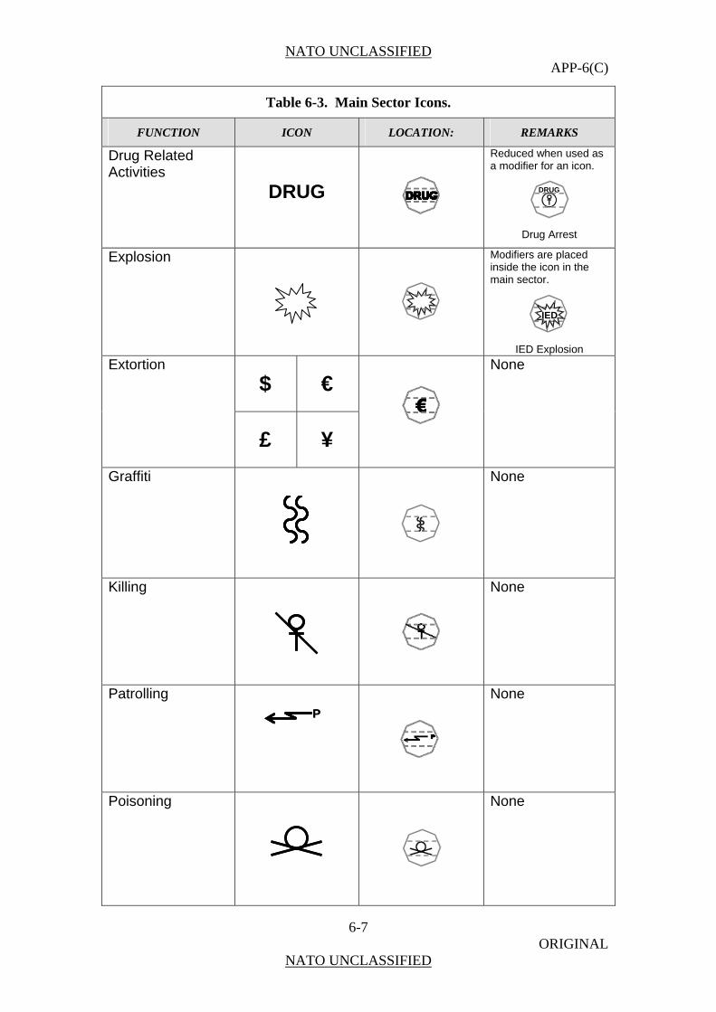
NATO UNCLASSIFIED APP-6(C)
6-7 ORIGINAL
NATO UNCLASSIFIED
Table 6-3. Main Sector Icons.
FUNCTION ICON LOCATION: REMARKS
Drug Related Activities
DRUG
Reduced when used as a modifier for an icon.
Drug Arrest
Explosion
Modifiers are placed inside the icon in the main sector.
IED Explosion
$
€
Extortion
£
¥
None
Graffiti
None
Killing
None
Patrolling PP
None
Poisoning
None
IED
DRUG
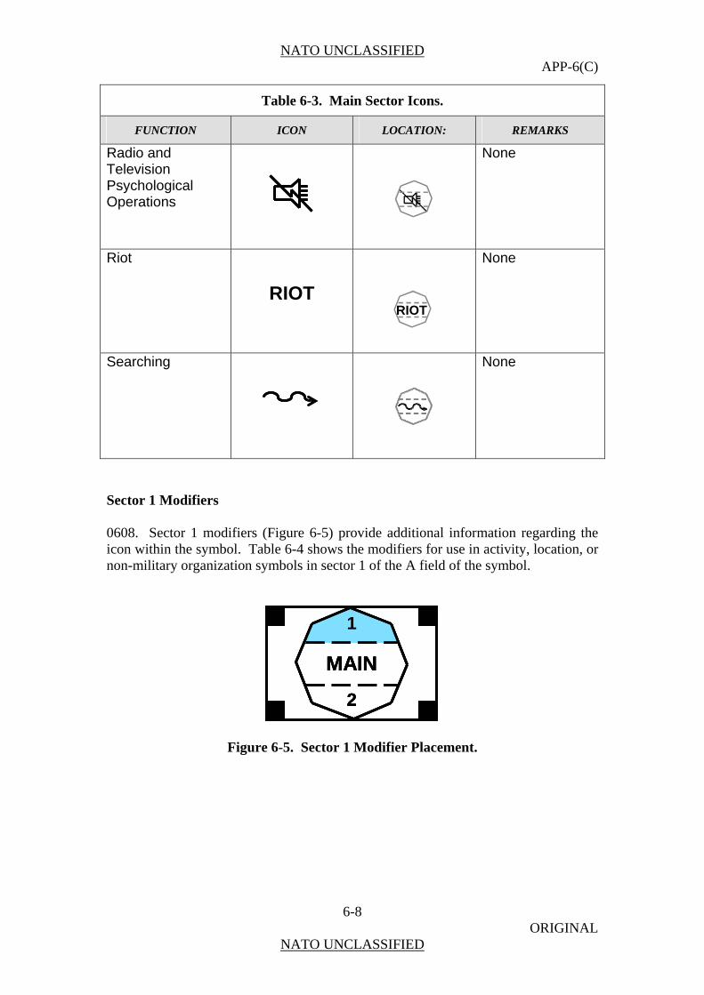
NATO UNCLASSIFIED APP-6(C)
6-8 ORIGINAL
NATO UNCLASSIFIED
Table 6-3. Main Sector Icons.
FUNCTION ICON LOCATION: REMARKS
Radio and Television Psychological Operations
None
Riot
RIOT
None
Searching
None
Sector 1 Modifiers 0608. Sector 1 modifiers (Figure 6-5) provide additional information regarding the icon within the symbol. Table 6-4 shows the modifiers for use in activity, location, or non-military organization symbols in sector 1 of the A field of the symbol.
MAIN
1
2
MAIN
1
2
MAIN
1
2
Figure 6-5. Sector 1 Modifier Placement.
RIOT
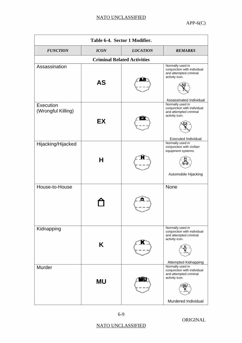
NATO UNCLASSIFIED APP-6(C)
6-9 ORIGINAL
NATO UNCLASSIFIED
Table 6-4. Sector 1 Modifier.
FUNCTION ICON LOCATION REMARKS
Criminal Related Activities
Assassination
AS
Normally used in conjunction with individual and attempted criminal activity icon.
Assassinated Individual
Execution (Wrongful Killing)
EX
Normally used in conjunction with individual and attempted criminal activity icon.
Executed Individual
Hijacking/Hijacked
H
Normally used in conjunction with civilian equipment systems.
Automobile Hijacking
House-to-House
None
Kidnapping
K
Normally used in conjunction with individual and attempted criminal activity icon.
Attempted Kidnapping
Murder
MU
Normally used in conjunction with individual and attempted criminal activity icon.
Murdered Individual
AS
EX
H
K
MU
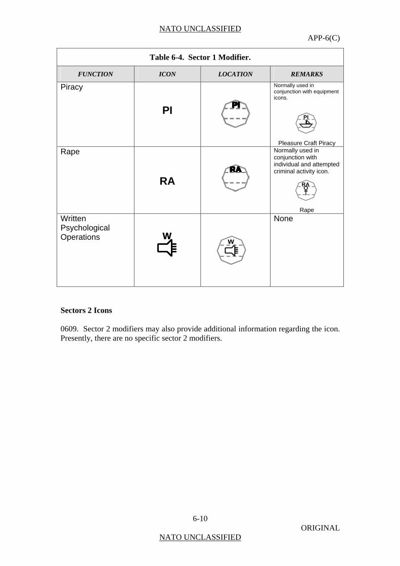
NATO UNCLASSIFIED APP-6(C)
6-10 ORIGINAL
NATO UNCLASSIFIED
Table 6-4. Sector 1 Modifier.
FUNCTION ICON LOCATION REMARKS
Piracy
PI
Normally used in conjunction with equipment icons.
Pleasure Craft Piracy
Rape
RA
Normally used in conjunction with individual and attempted criminal activity icon.
Rape
Written Psychological Operations
WW
None
w
RA
PI
Sectors 2 Icons 0609. Sector 2 modifiers may also provide additional information regarding the icon. Presently, there are no specific sector 2 modifiers.

NATO UNCLASSIFIED APP-6(C)
7-1 ORIGINAL
NATO UNCLASSIFIED
CHAPTER 7
CONTROL MEASURE SYMBOLS
General
0701. Ultimately, the joint force commander and his forces must be capable of accomplishing their mission, either directly or indirectly, by the employment of capabilities to create physical or psychological effects, and be able to sustain such operations for as long as is necessary to achieve operational objectives. The principal method by which this capability is delivered is through the combination of joint operational capabilities and a range of mechanisms and control measures. This chapter establishes a standard system for the development and use of control measures symbols. Within this standard system there are series of control measure symbols that follow standard formats and there are control measure symbols that follow stand alone formats. This chapter provides rules for automated and hand-drawn symbols and examples for all control measure symbols. These control measure symbols are the standard for all command and control systems and simulations, including those used in live, virtual, and constructive environments. For many control measure symbols, there is a corresponding definition provided in this section. These definitions are provided to help add clarity in using these symbols. For ease of understanding and use the control measure symbols have been broken down into groups that correspond to the joint functions of command and control to include joint targeting, manoeuvre and fires, intelligence, force protection, sustainment, and deception under information operations. Colouring 0702. All friendly graphic control measures will be shown in black or blue when drawn manually or on a colour computer-generated display. Hostile graphic control measures will be shown in red. If red is not available, they will be drawn in black with the abbreviation “ENY” placed on the graphic in at least two places. All obstacles as shown in this chapter, friendly, hostile, neutral, unknown or factional, will be drawn using the colour green. If the colour green is not available obstacles should be drawn using black. The colour yellow will be used for the cross-
NATO UNCLASSIFIED APP-6(C)
7-2 ORIGINAL
NATO UNCLASSIFIED
hatching for CBRN contaminated areas. NOTE: The use of green and yellow for obstacles and CBRN is in contradiction to the standard identities.
Labelling 0703. Make all text labelling in upper case letters. The reader should be able to read the labels for all text labels of modifier or amplifier fields for control measures symbols when the bottom of the overlay is closest to the reader. Labelling written on an angle should be readable to the viewer so they do not have to turn their head.
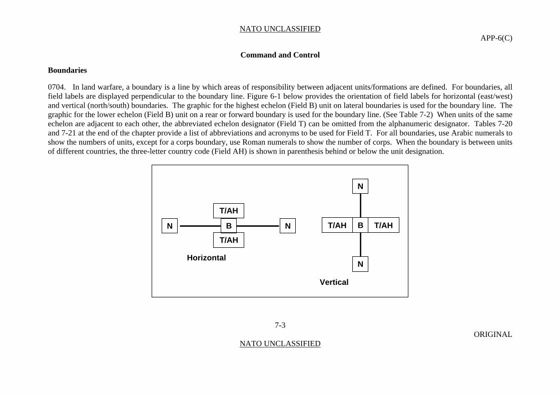
NATO UNCLASSIFIED APP-6(C)
Command and Control
Boundaries 0704. In land warfare, a boundary is a line by which areas of responsibility between adjacent units/formations are defined. For boundaries, all field labels are displayed perpendicular to the boundary line. Figure 6-1 below provides the orientation of field labels for horizontal (east/west) and vertical (north/south) boundaries. The graphic for the highest echelon (Field B) unit on lateral boundaries is used for the boundary line. The graphic for the lower echelon (Field B) unit on a rear or forward boundary is used for the boundary line. (See Table 7-2) When units of the same echelon are adjacent to each other, the abbreviated echelon designator (Field T) can be omitted from the alphanumeric designator. Tables 7-20 and 7-21 at the end of the chapter provide a list of abbreviations and acronyms to be used for Field T. For all boundaries, use Arabic numerals to show the numbers of units, except for a corps boundary, use Roman numerals to show the number of corps. When the boundary is between units of different countries, the three-letter country code (Field AH) is shown in parenthesis behind or below the unit designation.
N
T/AH
BT/AH T/AH BN N
T/AH
Horizontal N
Vertical
7-3 ORIGINAL
NATO UNCLASSIFIED

NATO UNCLASSIFIED APP-6(C)
Figure 7-1. Orientation of Boundary Lines.
Table 7-1. Boundaries.
CONTROL MEASURE
TEMPLATE DRAW RULES EXAMPLE Note: The symbols that have been coloured gray are used to help explain how the control measure is used, but they
are not a part of the control measure.
Friendly Present Boundary
7-4 ORIGINAL
NATO UNCLASSIFIED
Anchor Points. This graphic requires at least two points, points 1 and 2, to define the line. Additional points can be defined to extend and shape the line.
Friendly Planned or On Order Boundary
Enemy Known Boundary
Monochrome
Size/Shape. The first and last anchor points determine the length of the line. The line segment between each pair of anchor points will repeat all information associated with the line segment between points 1 and 2. Orientation. Orientation is determined by the anchor points.
PT 2
2ID (USA)T/AH
PT 1
B XX
52ID (GBR)T/AH
PT 2
1ID (CAN)T/AH
PT 1
B XX
2AD (FRA)T/AH
12INT/AH
I IENY ENYBN N7INT/AH
PT PT 2

NATO UNCLASSIFIED APP-6(C)
7-5 ORIGINAL
NATO UNCLASSIFIED
Table 7-1. Boundaries.
CONTROL TEMPLATE DRAW RULES EXAMPLE MEASURE Note: The symbols that have been coloured gray are used
to help explain how the control measure is used, but they are not a part of the control measure.
Colour
Enemy Suspected or Templated Boundary
PT 2
1AAB T/AH
PT 1
B
T/AH
PT 2 PT 1
T/AH
B
T/AH
PT 2
T/AH
B
T/AH
NN
PT
X
3ARBN
211AR
I IENY ENY
12ARCOY
3ABB
X
8ABR
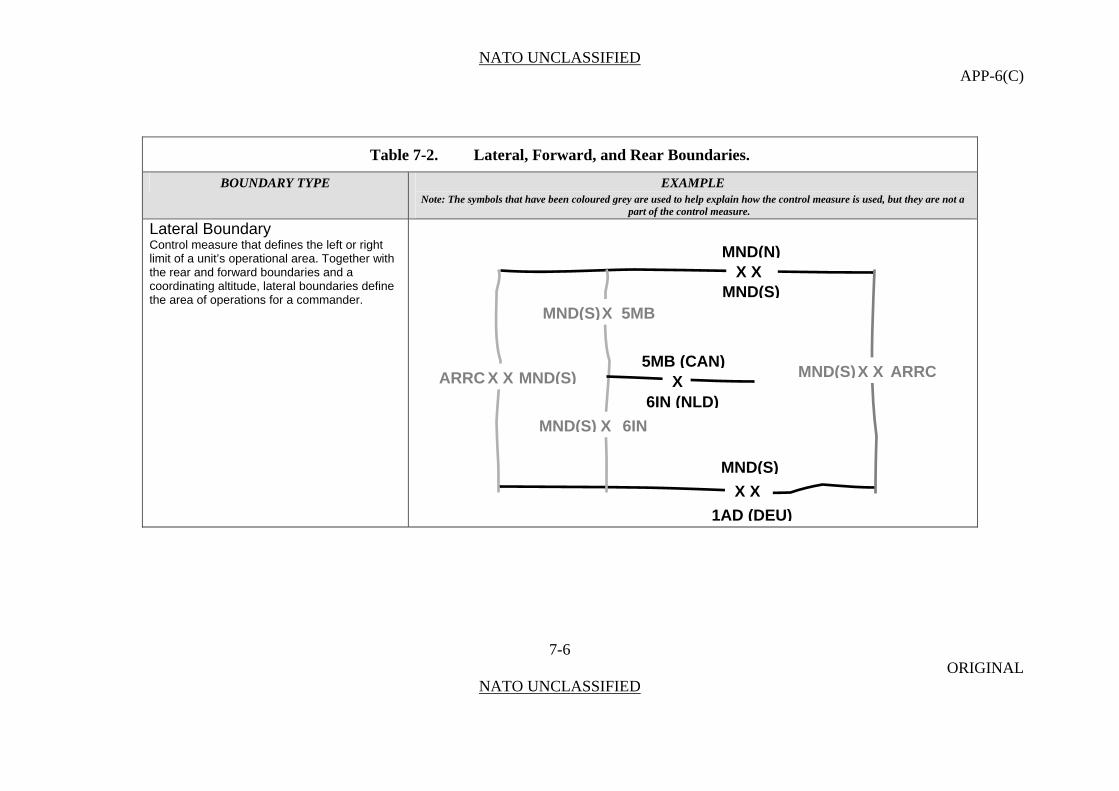
NATO UNCLASSIFIED APP-6(C)
Table 7-2. Lateral, Forward, and Rear Boundaries.
BOUNDARY TYPE EXAMPLE Note: The symbols that have been coloured grey are used to help explain how the control measure is used, but they are not a
part of the control measure.
Lateral Boundary Control measure that defines the left or right limit of a unit’s operational area. Together with the rear and forward boundaries and a coordinating altitude, lateral boundaries define the area of operations for a commander.
7-6 ORIGINAL
NATO UNCLASSIFIED
MND(N) X X
MND(S) XMND(S) 5MB
XMND(S) 6IN
X5MB (CAN)
XMND(S) X ARRC X X ARRC MND(S)
6IN (NLD)
MND(S)
X X
1AD (DEU)

NATO UNCLASSIFIED APP-6(C)
Table 7-2. Lateral, Forward, and Rear Boundaries.
BOUNDARY TYPE EXAMPLE Note: The symbols that have been coloured grey are used to help explain how the control measure is used, but they are not a
part of the control measure.
Forward Boundary The farthest limit, in the direction of the enemy, of an organization’s responsibility.
7-7 ORIGINAL
NATO UNCLASSIFIED
MND(N) X X
MND(S) XMND(S) 5MB
1AD (DEU)
XMND(S) 6IN
X5MB (CAN)
XMND(S) X ARRC X X ARRC MND(S)
6IN (NLD)
MND(S)
X X
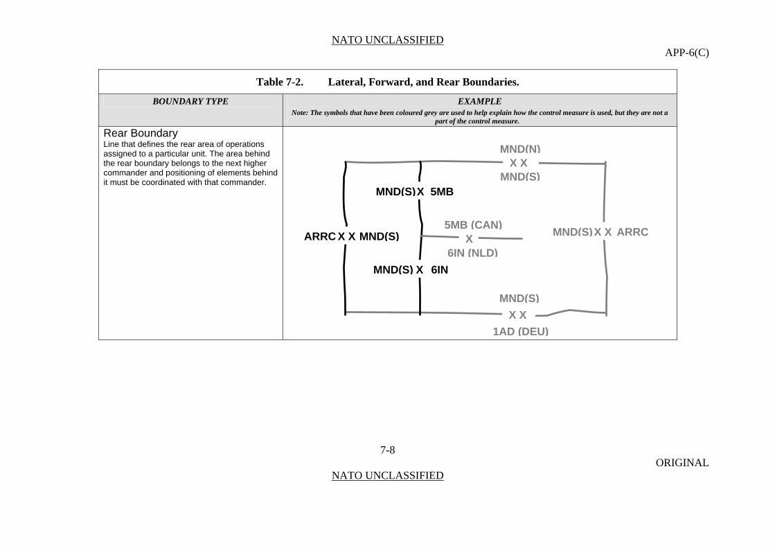
NATO UNCLASSIFIED APP-6(C)
Table 7-2. Lateral, Forward, and Rear Boundaries.
BOUNDARY TYPE EXAMPLE Note: The symbols that have been coloured grey are used to help explain how the control measure is used, but they are not a
part of the control measure.
Rear Boundary Line that defines the rear area of operations assigned to a particular unit. The area behind the rear boundary belongs to the next higher commander and positioning of elements behind it must be coordinated with that commander.
7-8 ORIGINAL
NATO UNCLASSIFIED
MND(N) X X
MND(S) XMND(S) 5MB
1AD (DEU)
XMND(S) 6IN
X5MB (CAN)
XMND(S) X ARRC X X ARRC MND(S)
6IN (NLD)
MND(S)
X X
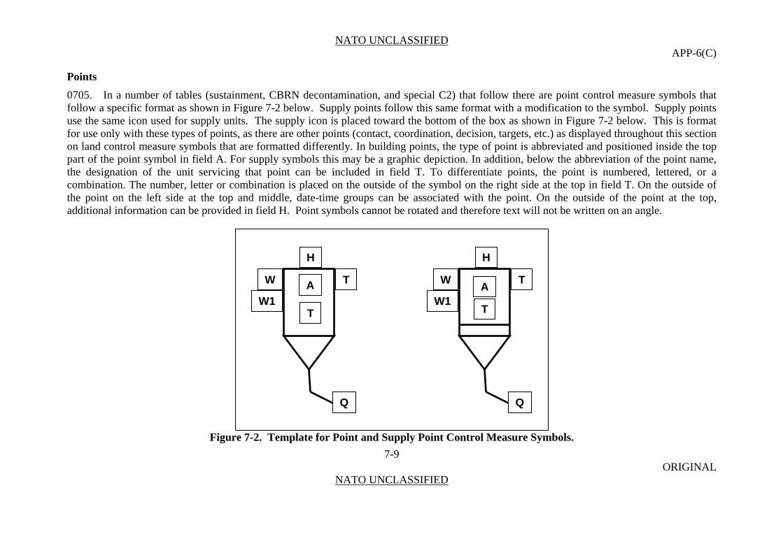
NATO UNCLASSIFIED APP-6(C)
Points
0705. In a number of tables (sustainment, CBRN decontamination, and special C2) that follow there are point control measure symbols that follow a specific format as shown in Figure 7-2 below. Supply points follow this same format with a modification to the symbol. Supply points use the same icon used for supply units. The supply icon is placed toward the bottom of the box as shown in Figure 7-2 below. This is format for use only with these types of points, as there are other points (contact, coordination, decision, targets, etc.) as displayed throughout this section on land control measure symbols that are formatted differently. In building points, the type of point is abbreviated and positioned inside the top part of the point symbol in field A. For supply symbols this may be a graphic depiction. In addition, below the abbreviation of the point name, the designation of the unit servicing that point can be included in field T. To differentiate points, the point is numbered, lettered, or a combination. The number, letter or combination is placed on the outside of the symbol on the right side at the top in field T. On the outside of the point on the left side at the top and middle, date-time groups can be associated with the point. On the outside of the point at the top, additional information can be provided in field H. Point symbols cannot be rotated and therefore text will not be written on an angle.
7-9 ORIGINAL
NATO UNCLASSIFIED
Figure 7-2. Template for Point and Supply Point Control Measure Symbols.
H
T
TW
W1 A
H
W TA
W1T
Q Q
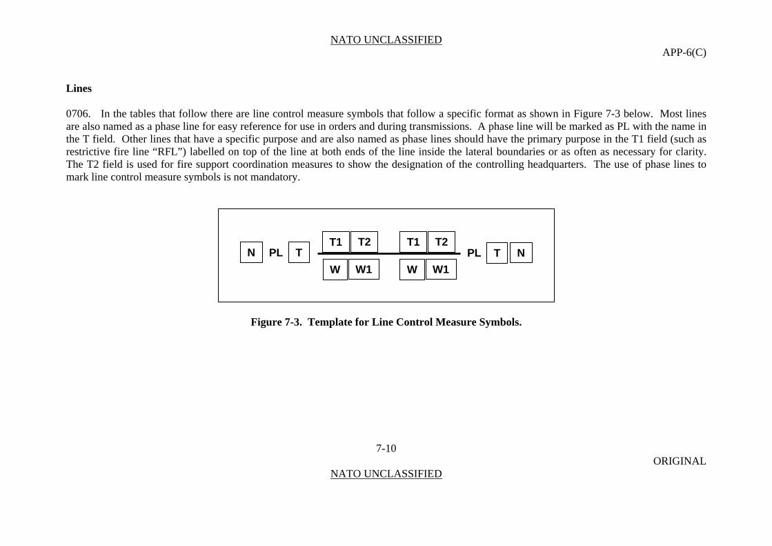
NATO UNCLASSIFIED APP-6(C)
Lines
0706. In the tables that follow there are line control measure symbols that follow a specific format as shown in Figure 7-3 below. Most lines are also named as a phase line for easy reference for use in orders and during transmissions. A phase line will be marked as PL with the name in the T field. Other lines that have a specific purpose and are also named as phase lines should have the primary purpose in the T1 field (such as restrictive fire line “RFL”) labelled on top of the line at both ends of the line inside the lateral boundaries or as often as necessary for clarity. The T2 field is used for fire support coordination measures to show the designation of the controlling headquarters. The use of phase lines to mark line control measure symbols is not mandatory.
7-10 ORIGINAL
NATO UNCLASSIFIED
Figure 7-3. Template for Line Control Measure Symbols.
T1T2 T2 T1N PL T PL NT
WW1 W1 W
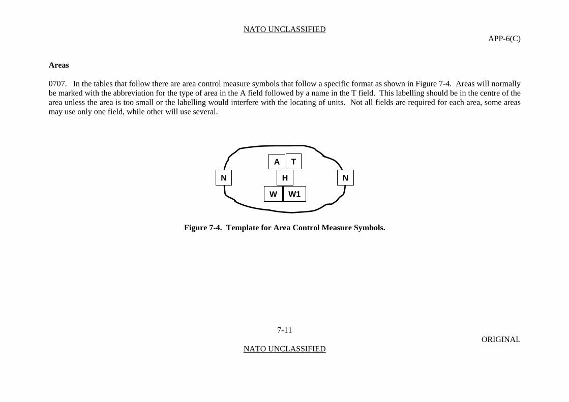
NATO UNCLASSIFIED APP-6(C)
Areas 0707. In the tables that follow there are area control measure symbols that follow a specific format as shown in Figure 7-4. Areas will normally be marked with the abbreviation for the type of area in the A field followed by a name in the T field. This labelling should be in the centre of the area unless the area is too small or the labelling would interfere with the locating of units. Not all fields are required for each area, some areas may use only one field, while other will use several.
7-11 ORIGINAL
NATO UNCLASSIFIED
TA
N H N
W1W
Figure 7-4. Template for Area Control Measure Symbols.

NATO UNCLASSIFIED APP-6(C)
Area of Operations
0708. An area of operations is an operational area defined by a joint commander for land or maritime forces to conduct military activities. Normally, an area of operations does not encompass the entire joint operations area of the joint commander, but is sufficient in size for the joint force component commander to accomplish assigned missions and protect forces. Operational area is an overarching term encompassing more descriptive terms for geographic areas in which military operations are conducted. Operational areas include, but are not limited to, such descriptors as area of responsibility, theatre of war, theatre of operations, joint operations area, amphibious objective area, joint special operations area, and area of operations.
Table 7-3. Area of Operations.
CONTROL TEMPLATE DRAW RULES EXAMPLE MEASURE Note: The symbols that have been coloured grey are used
to help explain how the control measure is used, but they are not a part of the control measure.
Area of Operations
Anchor Points. This graphic requires at least three anchor points to define the boundary of the area. Add as many points as necessary to accurately reflect the area’s size and shape.
7-12 ORIGINAL
NATO UNCLASSIFIED
Size/Shape. Determined
AO BUFFALOTAO
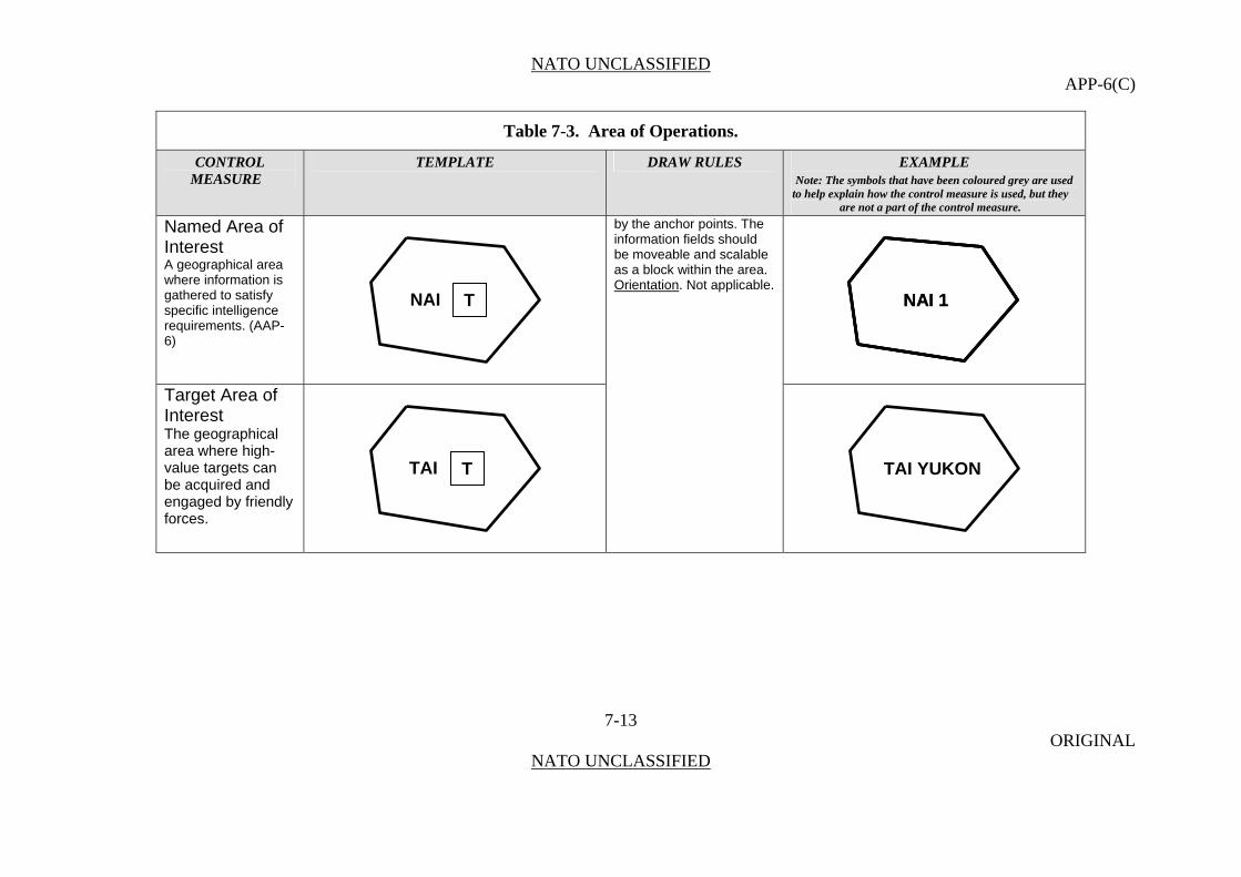
NATO UNCLASSIFIED APP-6(C)
Table 7-3. Area of Operations.
CONTROL TEMPLATE DRAW RULES EXAMPLE MEASURE Note: The symbols that have been coloured grey are used
to help explain how the control measure is used, but they are not a part of the control measure.
Named Area of Interest
7-13 ORIGINAL
NATO UNCLASSIFIED
A geographical area where information is gathered to satisfy specific intelligence requirements. (AAP-6)
NAI 1 NAI 1
by the anchor points. The information fields should be moveable and scalable as a block within the area. Orientation
Target Area of Interest The geographical area where high-value targets can be acquired and engaged by friendly forces.
. Not applicable. NAI T
TAI T TAI YUKON

NATO UNCLASSIFIED APP-6(C)
Command and Control Measure Symbols 0709. These symbols are used in the exercise of authority and direction by a properly designated commander over assigned and attached forces in the accomplishment of the mission.
Table 7-4. Command and Control Measure Symbols.
CONTROL TEMPLATE DRAW RULES EXAMPLE MEASURE Note: The symbols that have been coloured grey are used
to help explain how the control measure is used, but they are not a part of the control measure.
Points Unspecified Control Point
Anchor Points. This graphic requires one anchor point. The point defines the tip of the inverted cone.
Examples follow.
7-14 ORIGINAL
NATO UNCLASSIFIED
Size/Shape. Static. Orientation. The graphic will typically be oriented upright, as shown in the example to the right.
H
W T
T
A
W1
ANCHORPOINT

NATO UNCLASSIFIED APP-6(C)
Table 7-4. Command and Control Measure Symbols.
CONTROL TEMPLATE DRAW RULES EXAMPLE MEASURE Note: The symbols that have been coloured grey are used
to help explain how the control measure is used, but they are not a part of the control measure.
Amnesty Point
7-15 ORIGINAL
NATO UNCLASSIFIED
AMN
UN
080700ZMAY08-120700ZMAY08
WEAPONS
AMN
UN
AMN
UN
080700ZMAY08-120700ZMAY08
WEAPONS
H
AMN W T
W1T
ANCHORPOINT

NATO UNCLASSIFIED APP-6(C)
Table 7-4. Command and Control Measure Symbols.
CONTROL TEMPLATE DRAW RULES EXAMPLE MEASURE Note: The symbols that have been coloured grey are used
to help explain how the control measure is used, but they are not a part of the control measure.
Checkpoint
7-16 ORIGINAL
NATO UNCLASSIFIED
A predetermined point on the surface of the earth used as a means of controlling movement, a registration target for fire adjustment, or reference for location. (AAP-6)
CKP 4
CKP 4
Centre of Main Effort
Anchor Points. This graphic requires one anchor point. The centre point defines the centre of the symbol. Size/Shape. Static. Orientation. The graphic is typically centred over the desired location. Note: For the Centre of Main effort, the symbol can be rotated so that the lines at the top of the symbol are oriented toward the point of main effort.
H
W TCKP
W1T
ANCHORPOINT
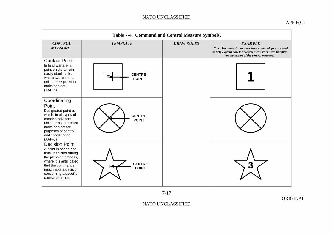
NATO UNCLASSIFIED APP-6(C)
Table 7-4. Command and Control Measure Symbols.
CONTROL TEMPLATE DRAW RULES EXAMPLE MEASURE Note: The symbols that have been coloured grey are used
to help explain how the control measure is used, but they are not a part of the control measure.
Contact Point
7-17 ORIGINAL
NATO UNCLASSIFIED
In land warfare, a point on the terrain, easily identifiable, where two or more units are required to make contact. (AAP-6)
Coordinating Point Designated point at which, in all types of combat, adjacent units/formations must make contact for purposes of control and coordination. (AAP-6)
Decision Point A point in space and time, identified during the planning process, where it is anticipated that the commander must make a decision concerning a specific course of action.
1CENTREPOINT T
CENTRE POINT
3CENTRE POINT T

NATO UNCLASSIFIED APP-6(C)
Table 7-4. Command and Control Measure Symbols.
CONTROL TEMPLATE DRAW RULES EXAMPLE MEASURE Note: The symbols that have been coloured grey are used
to help explain how the control measure is used, but they are not a part of the control measure.
Linkup Point Anchor Points. This graphic requires one anchor point. The point defines the tip of the inverted cone.
7-18 ORIGINAL
NATO UNCLASSIFIED
A point where two infiltrating elements in the same or different infiltration lanes are scheduled to meet to consolidate before proceeding with their missions.
Size/Shape. Static. Orientation. The graphic will typically be oriented upright, as shown in the example to the right, but will be rotated in 90 degree increments .
LU
3BN
1LU
3BN
1
H
W TLU
W1T
ANCHORPOINT
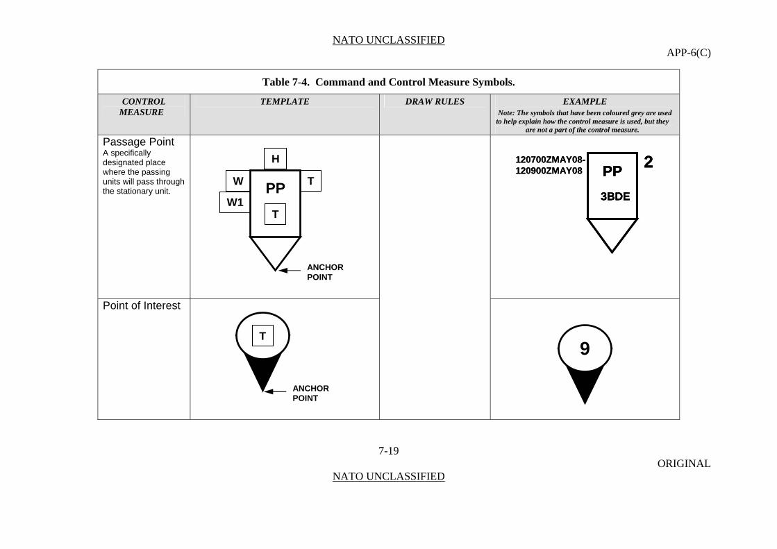
NATO UNCLASSIFIED APP-6(C)
Table 7-4. Command and Control Measure Symbols.
CONTROL TEMPLATE DRAW RULES EXAMPLE MEASURE Note: The symbols that have been coloured grey are used
to help explain how the control measure is used, but they are not a part of the control measure.
Passage Point
7-19 ORIGINAL
NATO UNCLASSIFIED
A specifically designated place where the passing units will pass through the stationary unit.
PP
3BDE
2120700ZMAY08-120900ZMAY08 PP
3BDE
2PP
3BDE
2120700ZMAY08-120900ZMAY08
Point of Interest
H
W TPP
W1T
ANCHORPOINT
T
ANCHORPOINT
9

NATO UNCLASSIFIED APP-6(C)
Table 7-4. Command and Control Measure Symbols.
CONTROL TEMPLATE DRAW RULES EXAMPLE MEASURE Note: The symbols that have been coloured grey are used
to help explain how the control measure is used, but they are not a part of the control measure.
Rally Point
RLY
A
RLY
A
7-20 ORIGINAL
NATO UNCLASSIFIED
An easily identifiable point on the ground at which units can reassemble and reorganize if they become dispersed.
H
W TRLY
W1T
ANCHORPOINT
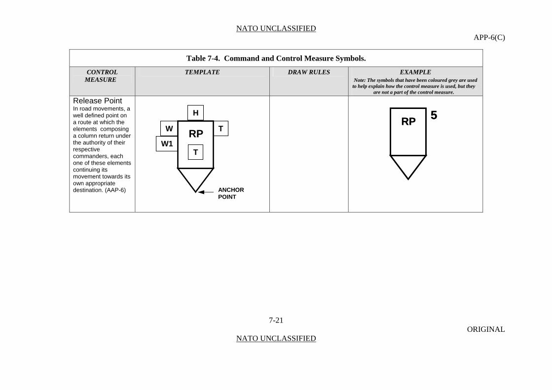
NATO UNCLASSIFIED APP-6(C)
Table 7-4. Command and Control Measure Symbols.
CONTROL TEMPLATE DRAW RULES EXAMPLE MEASURE Note: The symbols that have been coloured grey are used
to help explain how the control measure is used, but they are not a part of the control measure.
Release Point
7-21 ORIGINAL
NATO UNCLASSIFIED
In road movements, a well defined point on a route at which the elements composing a column return under the authority of their respective commanders, each one of these elements continuing its movement towards its own appropriate destination. (AAP-6)
RP 5
RP 5
H
W TRP
W1T
ANCHORPOINT
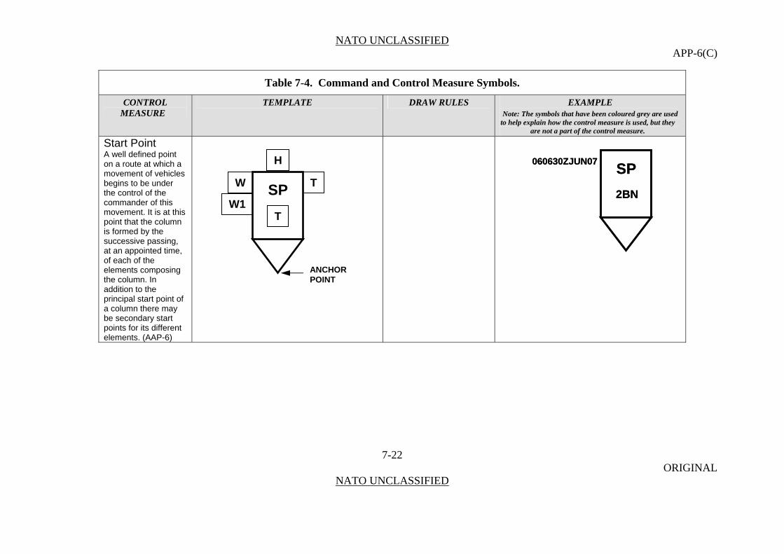
NATO UNCLASSIFIED APP-6(C)
Table 7-4. Command and Control Measure Symbols.
CONTROL TEMPLATE DRAW RULES EXAMPLE MEASURE Note: The symbols that have been coloured grey are used
to help explain how the control measure is used, but they are not a part of the control measure.
Start Point
SP
2BN
060630ZJUN07SP
2BN
060630ZJUN07
7-22 ORIGINAL
NATO UNCLASSIFIED
A well defined point on a route at which a movement of vehicles begins to be under the control of the commander of this movement. It is at this point that the column is formed by the successive passing, at an appointed time, of each of the elements composing the column. In addition to the principal start point of a column there may be secondary start points for its different elements. (AAP-6)
H
W TSP
W1T
ANCHORPOINT
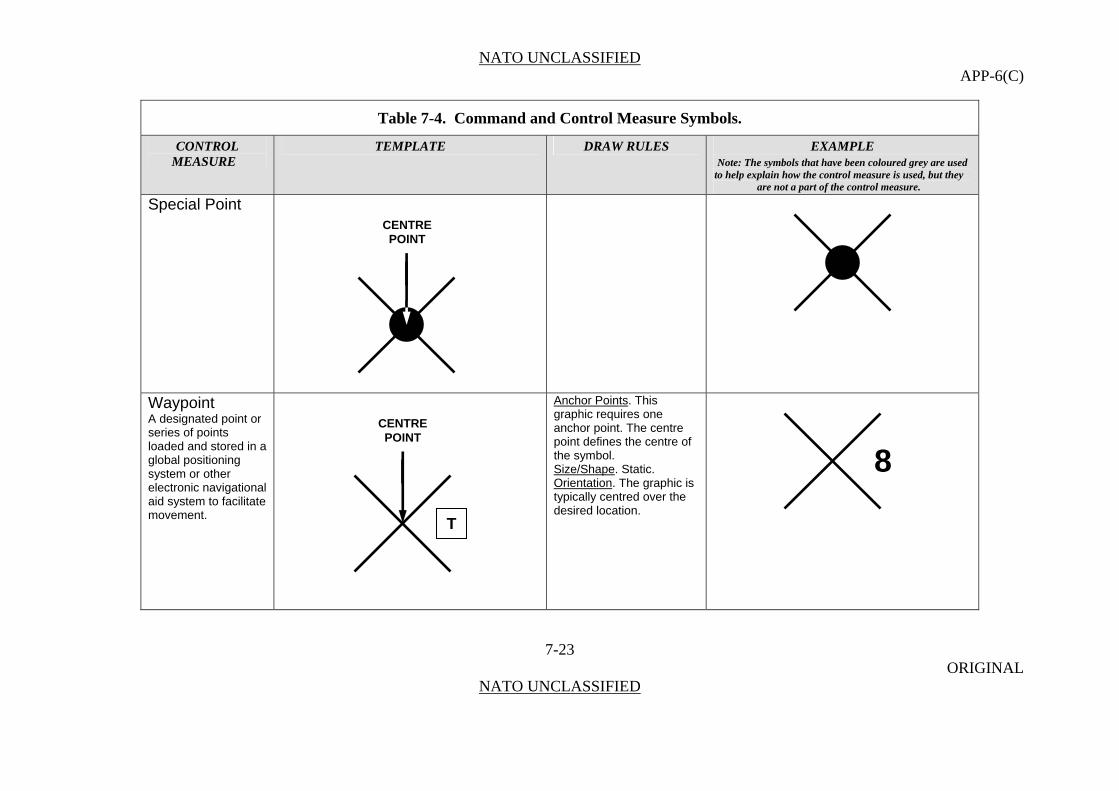
NATO UNCLASSIFIED APP-6(C)
Table 7-4. Command and Control Measure Symbols.
CONTROL TEMPLATE DRAW RULES EXAMPLE MEASURE Note: The symbols that have been coloured grey are used
to help explain how the control measure is used, but they are not a part of the control measure.
Special Point
7-23 ORIGINAL
NATO UNCLASSIFIED
CENTRE POINT
Waypoint Anchor Points. This graphic requires one anchor point. The centre point defines the centre of the symbol.
A designated point or series of points loaded and stored in a global positioning system or other electronic navigational aid system to facilitate movement.
Size/Shape. Static. Orientation. The graphic is typically centred over the desired location.
CENTRE POINT
8
T
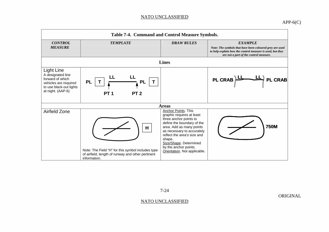
NATO UNCLASSIFIED APP-6(C)
Table 7-4. Command and Control Measure Symbols.
CONTROL TEMPLATE DRAW RULES EXAMPLE MEASURE Note: The symbols that have been coloured grey are used
to help explain how the control measure is used, but they are not a part of the control measure.
Lines
Light Line A designated line forward of which vehicles are required to use black-out lights at night. (AAP-6)
PL CRABPL CRAB LL LL
PL CRABPL CRAB LL LL
7-24 ORIGINAL
NATO UNCLASSIFIED
Areas
Airfield Zone
Note: The Field “H” for this symbol includes type of airfield, length of runway and other pertinent information.
Anchor Points. This graphic requires at least three anchor points to define the boundary of the area. Add as many points as necessary to accurately reflect the area’s size and shape. Size/Shape. Determined by the anchor points. Orientation. Not applicable.
750M750M
H
PT 2 PT 1
LL LL T TPL PL

NATO UNCLASSIFIED APP-6(C)
Manoeuvre
Manoeuvre Control Measure Symbols 0710. Manoeuvre is the employment of forces on the battlefield through movement in combination with fire, or fire potential, to achieve a position of advantage in respect to the enemy in order to accomplish the mission.
Table 7-5. Manoeuvre Control Measure Symbols.
CONTROL TEMPLATE DRAW RULES EXAMPLE MEASURE Note: The symbols that have been coloured grey are used
to help explain how the control measure is used, but they are not a part of the control measure.
Forward Line of Troops A line which indicates the most forward positions of forces in any kind of military operation at a specific time.
Friendly Present Anchor Points. This graphic requires at least two points, points 1 and 2, to define the line. Additional points can be defined to extend the line.
7-25 ORIGINAL
NATO UNCLASSIFIED
Size/Shape. The first and last anchor points determine the length of the line. The end-of line information will typically be posted at the ends of the line as it is displayed on the screen. Orientation. Orientation is determined by the order in which the anchor points are entered.
PT 2
PT 1 X
X
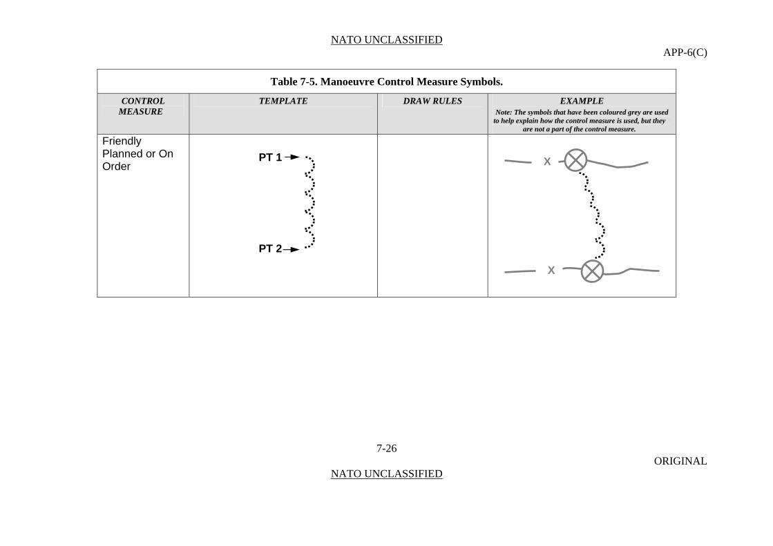
NATO UNCLASSIFIED APP-6(C)
Table 7-5. Manoeuvre Control Measure Symbols.
CONTROL TEMPLATE DRAW RULES EXAMPLE MEASURE Note: The symbols that have been coloured grey are used
to help explain how the control measure is used, but they are not a part of the control measure.
Friendly Planned or On Order
7-26 ORIGINAL
NATO UNCLASSIFIED
PT 2
PT 1 X
X

NATO UNCLASSIFIED APP-6(C)
Table 7-5. Manoeuvre Control Measure Symbols.
CONTROL TEMPLATE DRAW RULES EXAMPLE MEASURE Note: The symbols that have been coloured grey are used
to help explain how the control measure is used, but they are not a part of the control measure.
7-27 ORIGINAL
NATO UNCLASSIFIED
Enemy Known
N
N
PT 2
PT 1
PT 2
PT 1
ENY
ENY
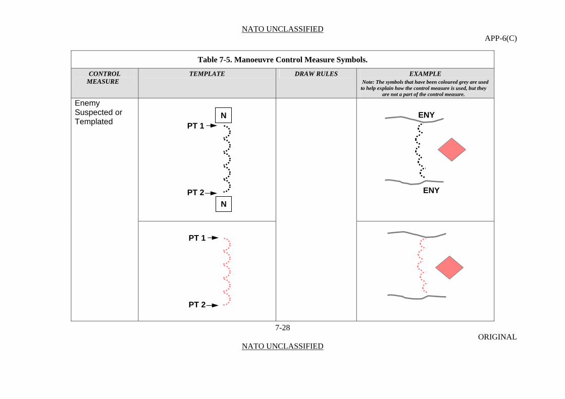
NATO UNCLASSIFIED APP-6(C)
Table 7-5. Manoeuvre Control Measure Symbols.
CONTROL TEMPLATE DRAW RULES EXAMPLE MEASURE Note: The symbols that have been coloured grey are used
to help explain how the control measure is used, but they are not a part of the control measure.
7-28 ORIGINAL
NATO UNCLASSIFIED
Enemy Suspected or Templated
N
N
PT 2
PT 1
PT 2
PT 1
ENY
ENY

NATO UNCLASSIFIED APP-6(C)
Table 7-5. Manoeuvre Control Measure Symbols.
CONTROL TEMPLATE DRAW RULES EXAMPLE MEASURE Note: The symbols that have been coloured grey are used
to help explain how the control measure is used, but they are not a part of the control measure.
Line of Contact The line of contact symbol is created when both the friendly and enemy forward line of troops symbols are displayed.
A general trace delineating the locations where two opposing forces are engaged.
7-29 ORIGINAL
NATO UNCLASSIFIED
Phase Line A line utilized for control and coordination of military operations, usually a terrain feature extending across the zone of action. (AAP-6)
Anchor Points. This graphic requires at least two points, points 1 and 2, to define the line. Additional points can be defined to extend the line. Size/Shape. The first and last anchor points determine the length of the line. The end-of line information will typically be posted at the ends of the line as it is displayed on the screen. Orientation. Orientation is determined by the anchor points.
ENY I
I ENY
PL ECHO PL ECHO T TPL PL
XX XX
PT 1 PT 2
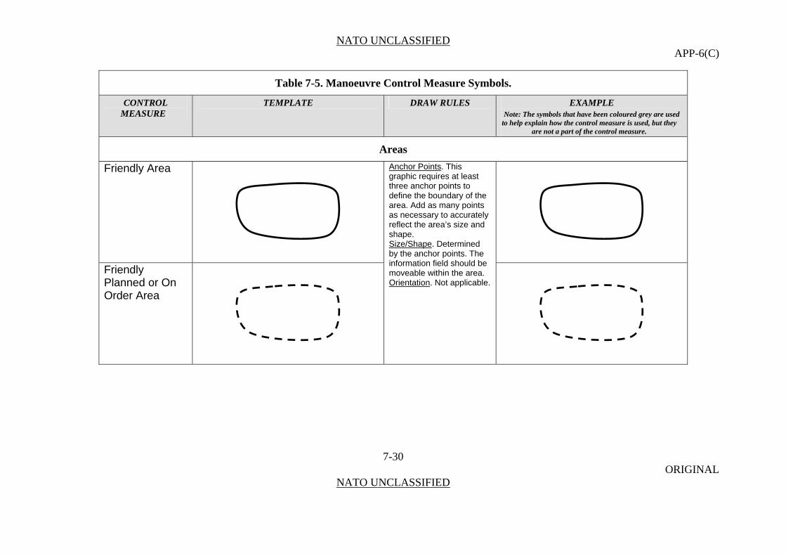
NATO UNCLASSIFIED APP-6(C)
Table 7-5. Manoeuvre Control Measure Symbols.
CONTROL TEMPLATE DRAW RULES EXAMPLE MEASURE Note: The symbols that have been coloured grey are used
to help explain how the control measure is used, but they are not a part of the control measure.
Areas
Friendly Area
7-30 ORIGINAL
NATO UNCLASSIFIED
Anchor Points. This graphic requires at least three anchor points to define the boundary of the area. Add as many points as necessary to accurately reflect the area’s size and shape. Size/Shape. Determined by the anchor points. The information field should be moveable within the area. Friendly
Planned or On Order Area
Orientation. Not applicable.
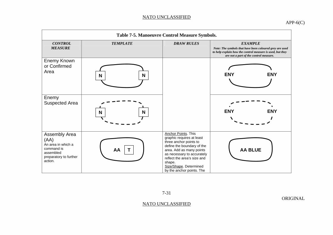
NATO UNCLASSIFIED APP-6(C)
Table 7-5. Manoeuvre Control Measure Symbols.
CONTROL TEMPLATE DRAW RULES EXAMPLE MEASURE Note: The symbols that have been coloured grey are used
to help explain how the control measure is used, but they are not a part of the control measure.
Enemy Known or Confirmed Area
7-31 ORIGINAL
NATO UNCLASSIFIED
Enemy Suspected Area
Assembly Area (AA) An area in which a command is assembled preparatory to further action.
Anchor Points. This graphic requires at least three anchor points to define the boundary of the area. Add as many points as necessary to accurately reflect the area’s size and shape. Size/Shape. Determined by the anchor points. The
ENY ENY NN
ENY ENY NN
AA AA BLUET

NATO UNCLASSIFIED APP-6(C)
Table 7-5. Manoeuvre Control Measure Symbols.
CONTROL TEMPLATE DRAW RULES EXAMPLE MEASURE Note: The symbols that have been coloured grey are used
to help explain how the control measure is used, but they are not a part of the control measure.
Occupied Assembly Area
7-32 ORIGINAL
NATO UNCLASSIFIED
information field should be moveable within the area. Orientation
Occupied Assembly Area with Offset Unit
Occupied Assembly Area with Offset Units
. Not applicable.
AA BLUE
AA BLUE
AA BLUE
AA T
A
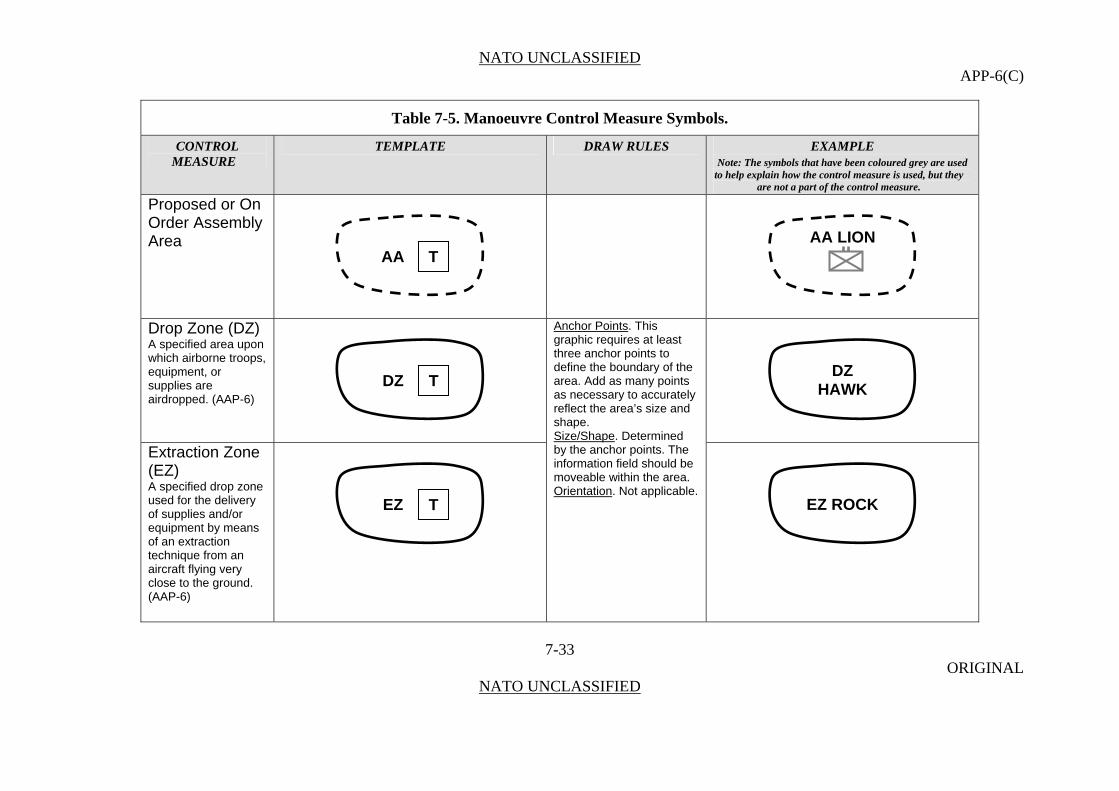
NATO UNCLASSIFIED APP-6(C)
Table 7-5. Manoeuvre Control Measure Symbols.
CONTROL TEMPLATE DRAW RULES EXAMPLE MEASURE Note: The symbols that have been coloured grey are used
to help explain how the control measure is used, but they are not a part of the control measure.
Proposed or On Order Assembly Area
7-33 ORIGINAL
NATO UNCLASSIFIED
AA LIONAA T
Drop Zone (DZ) A specified area upon which airborne troops, equipment, or supplies are airdropped. (AAP-6)
Anchor Points. This graphic requires at least three anchor points to define the boundary of the area. Add as many points as necessary to accurately reflect the area’s size and shape.
Extraction Zone (EZ) A specified drop zone used for the delivery of supplies and/or equipment by means of an extraction technique from an aircraft flying very close to the ground. (AAP-6)
Size/Shape. Determined by the anchor points. The information field should be moveable within the area. Orientation. Not applicable.
DZ DZ T HAWK
EZ ROCKEZ T

NATO UNCLASSIFIED APP-6(C)
Table 7-5. Manoeuvre Control Measure Symbols.
CONTROL TEMPLATE DRAW RULES EXAMPLE MEASURE Note: The symbols that have been coloured grey are used
to help explain how the control measure is used, but they are not a part of the control measure.
Landing Zone (LZ)
7-34 ORIGINAL
NATO UNCLASSIFIED
A specified zone used for the landing of aircraft on land, water or deck. (AAP-6)
Pickup Zone (PZ) A geographic area used to pick up troops or equipment by helicopter.
Fortified Area
Anchor Points. This graphic requires at least three anchor points to define the boundary of the area. Add as many points as necessary to accurately reflect the area’s size and shape. 2. Size/Shape. Determined by the anchor points. 3. Orientation. Not applicable.
LZ LZ T SILVER
PZ WOLFPZ T
T TANGO

NATO UNCLASSIFIED APP-6(C)
Table 7-5. Manoeuvre Control Measure Symbols.
CONTROL TEMPLATE DRAW RULES EXAMPLE MEASURE Note: The symbols that have been coloured grey are used
to help explain how the control measure is used, but they are not a part of the control measure.
Limited Access Area
Anchor Points. The area graphic requires at least three anchor points to define the boundary of the area. Add as many points as necessary to accurately reflect the area’s size and shape. The LAA point symbol requires one anchor point and is connected to the area graphic with a straight line.
7-35 ORIGINAL
NATO UNCLASSIFIED
Size/Shape. Determined by the anchor points. The information field should be moveable within the area. Orientation. The LAA point symbol will be oriented upright, as shown in the example to the right,
A
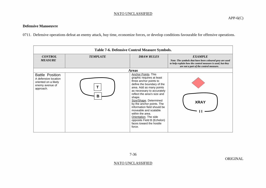
NATO UNCLASSIFIED APP-6(C)
Defensive Manoeuvre 0711. Defensive operations defeat an enemy attack, buy time, economize forces, or develop conditions favourable for offensive operations.
Table 7-6. Defensive Control Measure Symbols.
CONTROL TEMPLATE DRAW RULES EXAMPLE MEASURE Note: The symbols that have been coloured grey are used
to help explain how the control measure is used, but they are not a part of the control measure.
Areas Battle Position Anchor Points. This
graphic requires at least three anchor points to define the boundary of the area. Add as many points as necessary to accurately reflect the area’s size and shape.
7-36 ORIGINAL
NATO UNCLASSIFIED
A defensive location oriented on a likely enemy avenue of approach.
Size/Shape. Determined by the anchor points. The information field should be moveable and scalable within the area. Orientation. The side opposite Field B (Echelon) faces toward the hostile force.
T
B
XRAY
I I
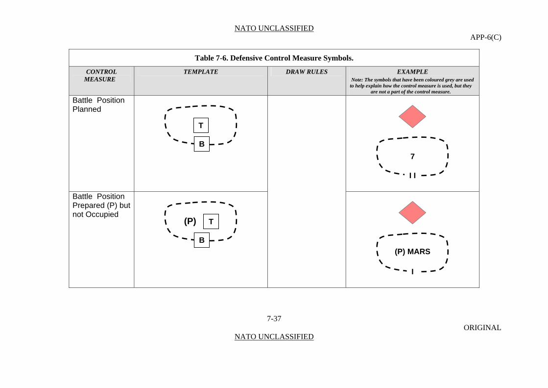
NATO UNCLASSIFIED APP-6(C)
Table 7-6. Defensive Control Measure Symbols.
CONTROL TEMPLATE DRAW RULES EXAMPLE MEASURE Note: The symbols that have been coloured grey are used
to help explain how the control measure is used, but they are not a part of the control measure.
Battle Position
7-37 ORIGINAL
NATO UNCLASSIFIED
Planned
Battle Position Prepared (P) but not Occupied
T
B
7
I I
(P) T
B
(P) MARS
I

NATO UNCLASSIFIED APP-6(C)
Table 7-6. Defensive Control Measure Symbols.
CONTROL TEMPLATE DRAW RULES EXAMPLE MEASURE Note: The symbols that have been coloured grey are used
to help explain how the control measure is used, but they are not a part of the control measure.
Strong Point
7-38 ORIGINAL
NATO UNCLASSIFIED
A key point in a defensive position, usually strongly fortified and heavily armed with automatic weapons, around which other positions are grouped for its protection. (AAP-6)
Engagement Area (EA) An area where the commander intends to contain and destroy an enemy force with the massed effects of all available weapons and supporting systems.
Anchor Points. This graphic requires at least three anchor points to define the boundary of the area. Add as many points as necessary to accurately reflect the area’s size and shape. Size/Shape. Determined by the anchor points. The information field should be moveable within the area. Orientation. Not applicable.
T
B
TWO
I
EA T
I
I
I
EA ROCK

NATO UNCLASSIFIED APP-6(C)
Table 7-6. Defensive Control Measure Symbols.
CONTROL TEMPLATE DRAW RULES EXAMPLE MEASURE Note: The symbols that have been coloured grey are used
to help explain how the control measure is used, but they are not a part of the control measure.
Observation Post /Outpost A position from which military observations are made, or fire directed and adjusted, and which possesses appropriate communications; may be airborne. Observation Post /Outpost
7-39 ORIGINAL
NATO UNCLASSIFIED
(Unspecified)
Anchor Points. This graphic requires one anchor point. The centre point defines the centre of the graphic.
Observation Post /Outpost (Specified)
Size/Shape. Static. Orientation. The graphic is typically centred over the desired location.
Examples follow.
CENTRE POINT
ACENTRE POINT

NATO UNCLASSIFIED APP-6(C)
Table 7-6. Defensive Control Measure Symbols.
CONTROL TEMPLATE DRAW RULES EXAMPLE MEASURE Note: The symbols that have been coloured grey are used
to help explain how the control measure is used, but they are not a part of the control measure.
Reconnaissance Outpost
7-40 ORIGINAL
NATO UNCLASSIFIED
Forward Observer Outpost
CBRN Observation Outpost
CENTRE POINT
CENTRE POINT
CENTRE POINT
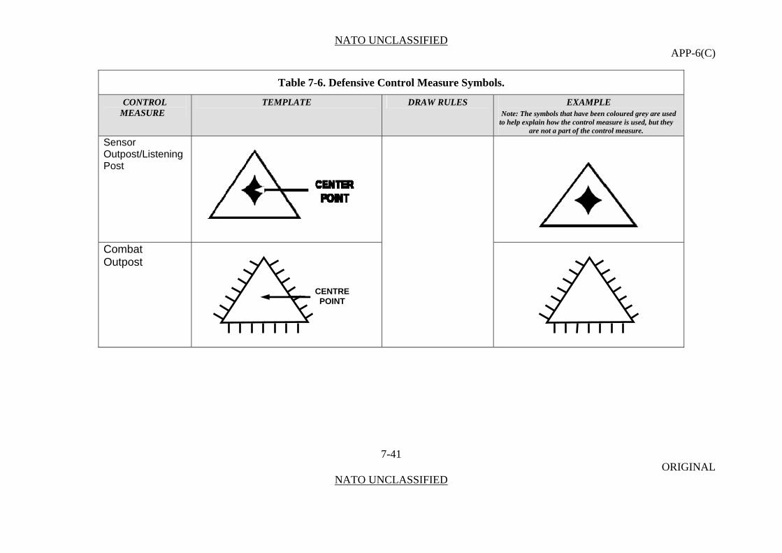
NATO UNCLASSIFIED APP-6(C)
Table 7-6. Defensive Control Measure Symbols.
CONTROL TEMPLATE DRAW RULES EXAMPLE MEASURE Note: The symbols that have been coloured grey are used
to help explain how the control measure is used, but they are not a part of the control measure.
Sensor Outpost/Listening Post
7-41 ORIGINAL
NATO UNCLASSIFIED
Combat Outpost
CENTRE POINT

NATO UNCLASSIFIED APP-6(C)
Table 7-6. Defensive Control Measure Symbols.
CONTROL TEMPLATE DRAW RULES EXAMPLE MEASURE Note: The symbols that have been coloured grey are used
to help explain how the control measure is used, but they are not a part of the control measure.
Target Reference Point
Anchor Points. This graphic requires one anchor point. The centre point defines the centre of the graphic.
7-42 ORIGINAL
NATO UNCLASSIFIED
An easily recognizable point on the ground (either natural or manmade) used to initiate, distribute, and control fires. Target reference points (TRPs) can also designate the centre of an area where the commander plans to distribute or converge the fires of all his weapons rapidly. They are used by task force and below, and can further delineate sectors of fire within an engagement area. TRPs are designated using the standard target symbol and numbers issued by the fire support officer. Once designated, TRPs also constitute indirect fire targets.
Size/Shape. Static. Orientation. The graphic is typically centred over the desired location.
PT 1 201 T

NATO UNCLASSIFIED APP-6(C)
Table 7-6. Defensive Control Measure Symbols.
CONTROL TEMPLATE DRAW RULES EXAMPLE MEASURE Note: The symbols that have been coloured grey are used
to help explain how the control measure is used, but they are not a part of the control measure.
Forward Edge of the Battle Area
7-43 ORIGINAL
NATO UNCLASSIFIED
The foremost limits of a series of areas in which ground combat units are deployed, excluding the areas in which the covering or screening forces are operating, designated to coordinate fire support, the positioning of forces or the manoeuvre of units. (AAP-6)
Anchor Points. This graphic requires at least two points, points 1 and 2, to define the line. Additional points can be defined to extend the line.
Proposed or On Order Forward Edge of the Battle Area
Size/Shape. The first and last anchor points determine the length of the line. The end-of line information will typically be posted at the ends of the line as it is displayed on the screen. Orientation. Orientation is determined by the order in which the anchor points are entered.
FEBA FEBA
PT 2 PT 1
FEBA FEBA
PT 2 PT 1
FEBA FEBA
PL KING PL KING 2 2
FEBA FEBA
PL INK PL INK
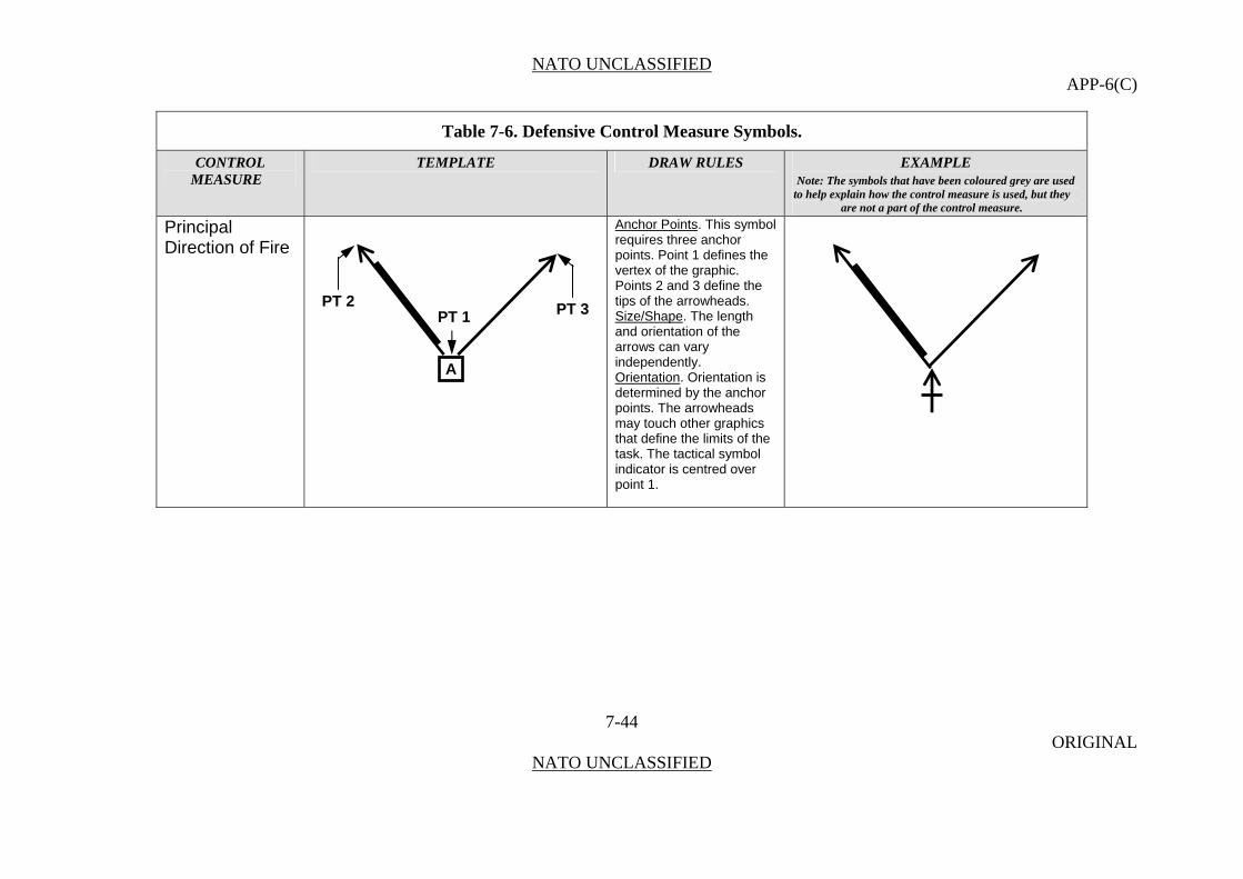
NATO UNCLASSIFIED APP-6(C)
Table 7-6. Defensive Control Measure Symbols.
CONTROL TEMPLATE DRAW RULES EXAMPLE MEASURE Note: The symbols that have been coloured grey are used
to help explain how the control measure is used, but they are not a part of the control measure.
Principal Direction of Fire
Anchor Points. This symbol requires three anchor points. Point 1 defines the vertex of the graphic. Points 2 and 3 define the tips of the arrowheads.
7-44 ORIGINAL
NATO UNCLASSIFIED
Size/Shape. The length and orientation of the arrows can vary independently. Orientation. Orientation is determined by the anchor points. The arrowheads may touch other graphics that define the limits of the task. The tactical symbol indicator is centred over point 1.
A
PT 2 PT 3 PT 1
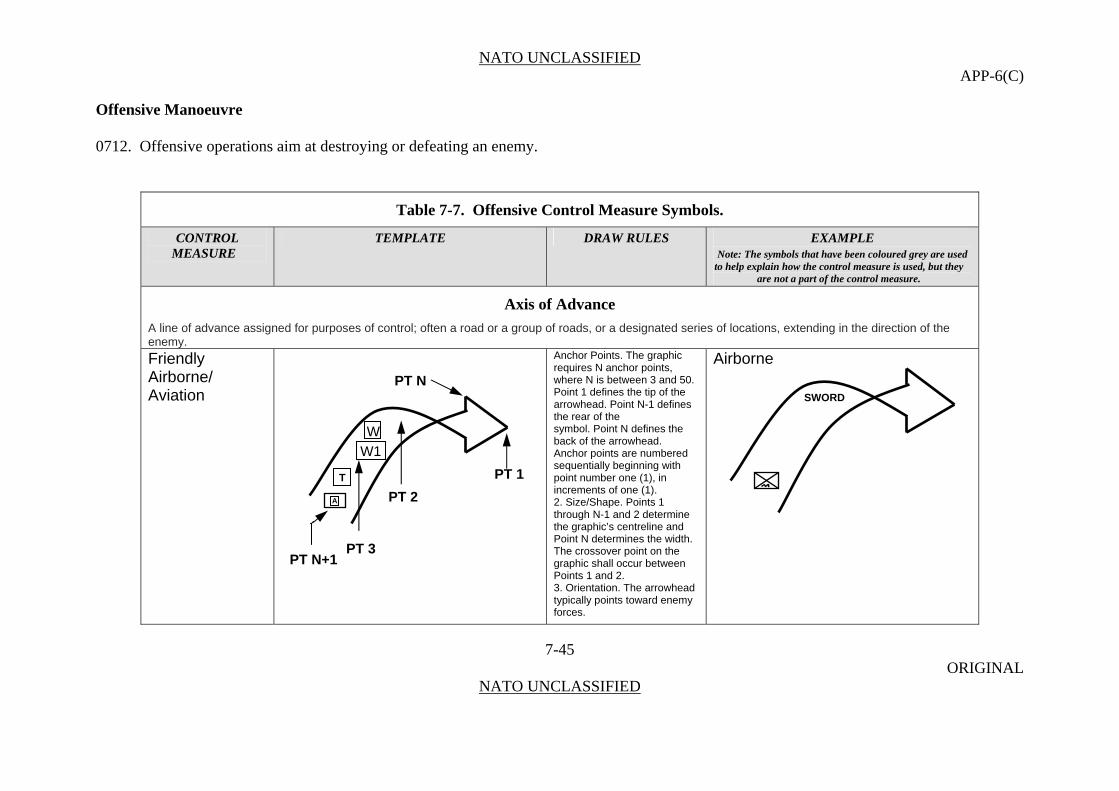
NATO UNCLASSIFIED APP-6(C)
Offensive Manoeuvre 0712. Offensive operations aim at destroying or defeating an enemy.
Table 7-7. Offensive Control Measure Symbols.
CONTROL TEMPLATE DRAW RULES EXAMPLE MEASURE Note: The symbols that have been coloured grey are used
to help explain how the control measure is used, but they are not a part of the control measure.
Axis of Advance
A line of advance assigned for purposes of control; often a road or a group of roads, or a designated series of locations, extending in the direction of the enemy. Friendly Airborne/
Airborne Anchor Points. The graphic requires N anchor points,
7-45 ORIGINAL
NATO UNCLASSIFIED
Aviation
where N is between 3 and 50. Point 1 defines the tip of the arrowhead. Point N-1 defines the rear of the symbol. Point N defines the back of the arrowhead. Anchor points are numbered sequentially beginning with point number one (1), in increments of one (1). 2. Size/Shape. Points 1 through N-1 and 2 determine the graphic’s centreline and Point N determines the width. The crossover point on the graphic shall occur between Points 1 and 2. 3. Orientation. The arrowhead typically points toward enemy forces.
A
PT N SWORD
PT 2
W
PT N+1
W1
PT 1 T
PT 3
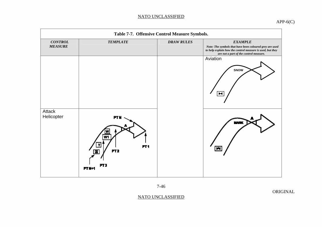
NATO UNCLASSIFIED APP-6(C)
Table 7-7. Offensive Control Measure Symbols.
CONTROL TEMPLATE DRAW RULES EXAMPLE MEASURE Note: The symbols that have been coloured grey are used
to help explain how the control measure is used, but they are not a part of the control measure.
Aviation
7-46 ORIGINAL
NATO UNCLASSIFIED
Attack Helicopter
SNOW

NATO UNCLASSIFIED APP-6(C)
Table 7-7. Offensive Control Measure Symbols.
CONTROL TEMPLATE DRAW RULES EXAMPLE MEASURE Note: The symbols that have been coloured grey are used
to help explain how the control measure is used, but they are not a part of the control measure.
Main Attack Anchor Points. The graphic requires N anchor points, where N is between 3 and 50. Point 1 defines the tip of the arrowhead. Point N-1 defines the rear of the symbol. Point N defines the back of the arrowhead.
7-47 ORIGINAL
NATO UNCLASSIFIED
The principal attack or effort into which the commander throws the full weight of the offensive power at his disposal. (AAP-6) Anchor points are
numbered sequentially beginning with point number one (1), in increments of one (1). Size/Shape. Points 1 through N-1 and 2 determine the graphic’s centreline and Point N
A
T
PT 2
PT N+1 PT 3
PT N
PT 1
W W1
WHITE

NATO UNCLASSIFIED APP-6(C)
Table 7-7. Offensive Control Measure Symbols.
CONTROL TEMPLATE DRAW RULES EXAMPLE MEASURE Note: The symbols that have been coloured grey are used
to help explain how the control measure is used, but they are not a part of the control measure.
Supporting Attack
determines the width. Orientation
7-48 ORIGINAL
NATO UNCLASSIFIED
An offensive operation carried out in conjunction with a main attack and designed to achieve one or more of the following: a. deceive the enemy; b. destroy or pin down enemy forces which could interfere with the main attack; c. control ground whose occupation by the enemy will hinder the main attack; or d. force the enemy to commit reserves prematurely or in an indecisive area. (AAP-6)
. The arrowhead typically points toward enemy forces.
PT 1 A
T
PT 2
PT N+1 PT 3
PT N
W W1
DAVID

NATO UNCLASSIFIED APP-6(C)
Table 7-7. Offensive Control Measure Symbols.
CONTROL TEMPLATE DRAW RULES EXAMPLE MEASURE Note: The symbols that have been coloured grey are used
to help explain how the control measure is used, but they are not a part of the control measure.
Supporting Attack Planned or On Order
7-49 ORIGINAL
NATO UNCLASSIFIED
A
PT 2
PT N
PT N+1
T
PT 3
PT 1
W W1
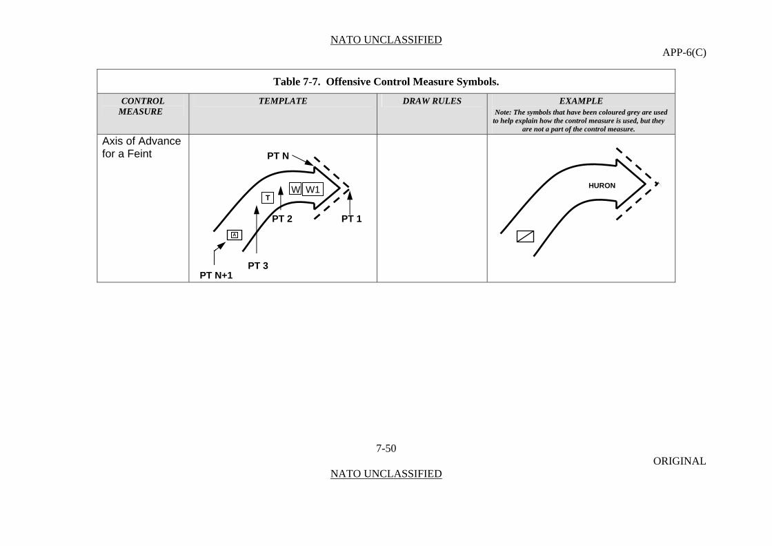
NATO UNCLASSIFIED APP-6(C)
Table 7-7. Offensive Control Measure Symbols.
CONTROL TEMPLATE DRAW RULES EXAMPLE MEASURE Note: The symbols that have been coloured grey are used
to help explain how the control measure is used, but they are not a part of the control measure.
Axis of Advance for a Feint
7-50 ORIGINAL
NATO UNCLASSIFIED
PT 1 A
T
PT 2
PT N+1 PT 3
PT N
W W1 HURON
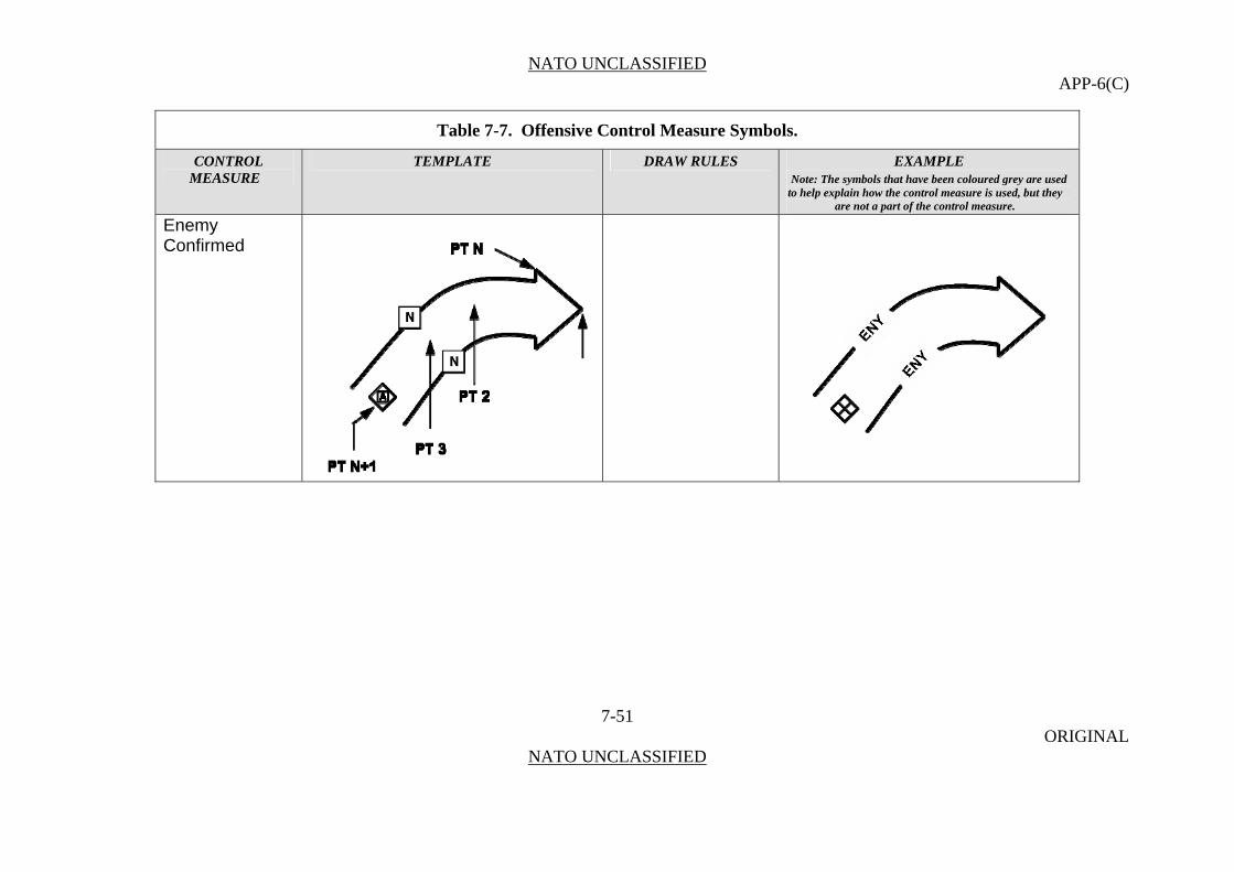
NATO UNCLASSIFIED APP-6(C)
Table 7-7. Offensive Control Measure Symbols.
CONTROL TEMPLATE DRAW RULES EXAMPLE MEASURE Note: The symbols that have been coloured grey are used
to help explain how the control measure is used, but they are not a part of the control measure.
Enemy Confirmed
7-51 ORIGINAL
NATO UNCLASSIFIED
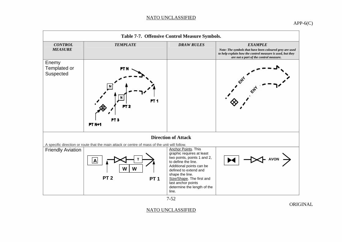
NATO UNCLASSIFIED APP-6(C)
Table 7-7. Offensive Control Measure Symbols.
CONTROL TEMPLATE DRAW RULES EXAMPLE MEASURE Note: The symbols that have been coloured grey are used
to help explain how the control measure is used, but they are not a part of the control measure.
Enemy Templated or Suspected
Direction of Attack
A specific direction or route that the main attack or centre of mass of the unit will follow.
Friendly Aviation Anchor Points. This graphic requires at least two points, points 1 and 2, to define the line. Additional points can be defined to extend and shape the line.
7-52 ORIGINAL
NATO UNCLASSIFIED
Size/Shape. The first and last anchor points determine the length of the line.
PT 2
T
PT 1
A AVON
W W

NATO UNCLASSIFIED APP-6(C)
Table 7-7. Offensive Control Measure Symbols.
CONTROL TEMPLATE DRAW RULES EXAMPLE MEASURE Note: The symbols that have been coloured grey are used
to help explain how the control measure is used, but they are not a part of the control measure.
Friendly Direction of Main Attack
7-53 ORIGINAL
NATO UNCLASSIFIED
Orientation. Orientation is determined by the anchor points.
MAIN
Friendly Direction of Supporting Attack
Friendly Ground Axis Planned or On Order with Effective Date and Time (if known)
PT 2
T
PT 1
A
W W
PT 2
TA
W W
PT 1
PT 2
T
PT 1
A YALU
W W
ORNE EFF110730ZFEB08
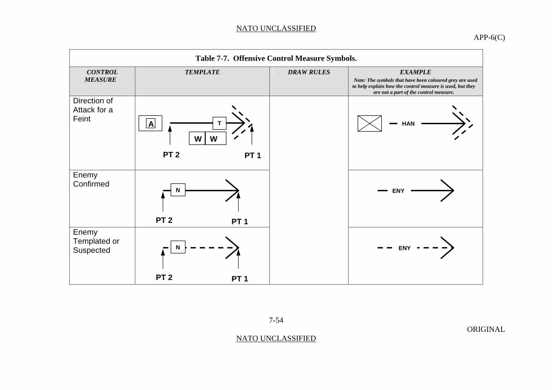
NATO UNCLASSIFIED APP-6(C)
Table 7-7. Offensive Control Measure Symbols.
CONTROL TEMPLATE DRAW RULES EXAMPLE MEASURE Note: The symbols that have been coloured grey are used
to help explain how the control measure is used, but they are not a part of the control measure.
Direction of Attack for a Feint
7-54 ORIGINAL
NATO UNCLASSIFIED
Enemy Confirmed
Enemy Templated or Suspected
PT 2
N
PT 1
PT 2
N
PT 1
PT 1
A T HAN
W W
PT 2
ENY
ENY

NATO UNCLASSIFIED APP-6(C)
Table 7-7. Offensive Control Measure Symbols.
CONTROL TEMPLATE DRAW RULES EXAMPLE MEASURE Note: The symbols that have been coloured grey are used
to help explain how the control measure is used, but they are not a part of the control measure.
Lines Final Coordination Line
Anchor Points. This graphic requires at least two points, points 1 and 2, to define the line. Additional points can be defined to extend the line.
7-55 ORIGINAL
NATO UNCLASSIFIED
A line close to the enemy position used to coordinate the lifting or shifting of supporting fires with the final deployment of manoeuvre elements.
Size/Shape. The first and last anchor points determine the length of the line. The end-of line information will typically be posted at the ends of the line as it is displayed on the screen. Orientation. Orientation is determined by the anchor points.
FCL FCLPL OPAL PL OPAL
2 X 3 3 X 1
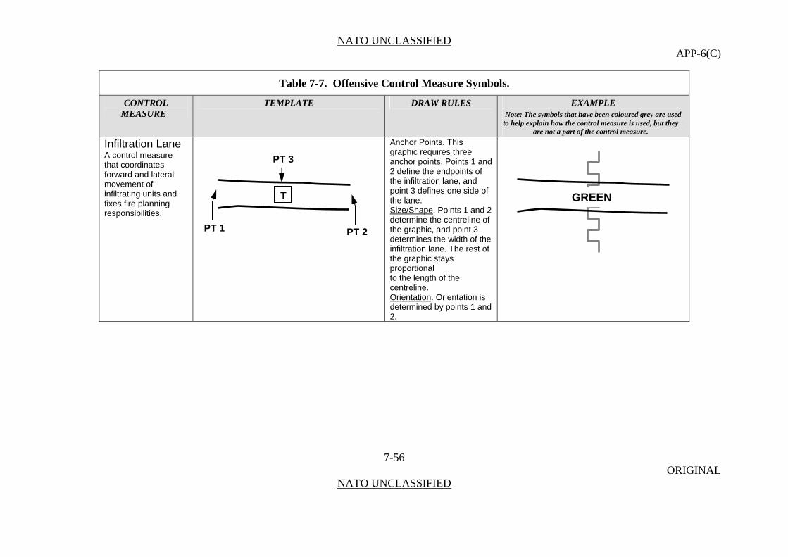
NATO UNCLASSIFIED APP-6(C)
Table 7-7. Offensive Control Measure Symbols.
CONTROL TEMPLATE DRAW RULES EXAMPLE MEASURE Note: The symbols that have been coloured grey are used
to help explain how the control measure is used, but they are not a part of the control measure.
Infiltration Lane Anchor Points. This graphic requires three anchor points. Points 1 and 2 define the endpoints of the infiltration lane, and point 3 defines one side of the lane.
7-56 ORIGINAL
NATO UNCLASSIFIED
A control measure that coordinates forward and lateral movement of infiltrating units and fixes fire planning responsibilities.
Size/Shape. Points 1 and 2 determine the centreline of the graphic, and point 3 determines the width of the infiltration lane. The rest of the graphic stays proportional to the length of the centreline. Orientation. Orientation is determined by points 1 and 2.
PT 3
T
PT 2 PT 1
GREEN
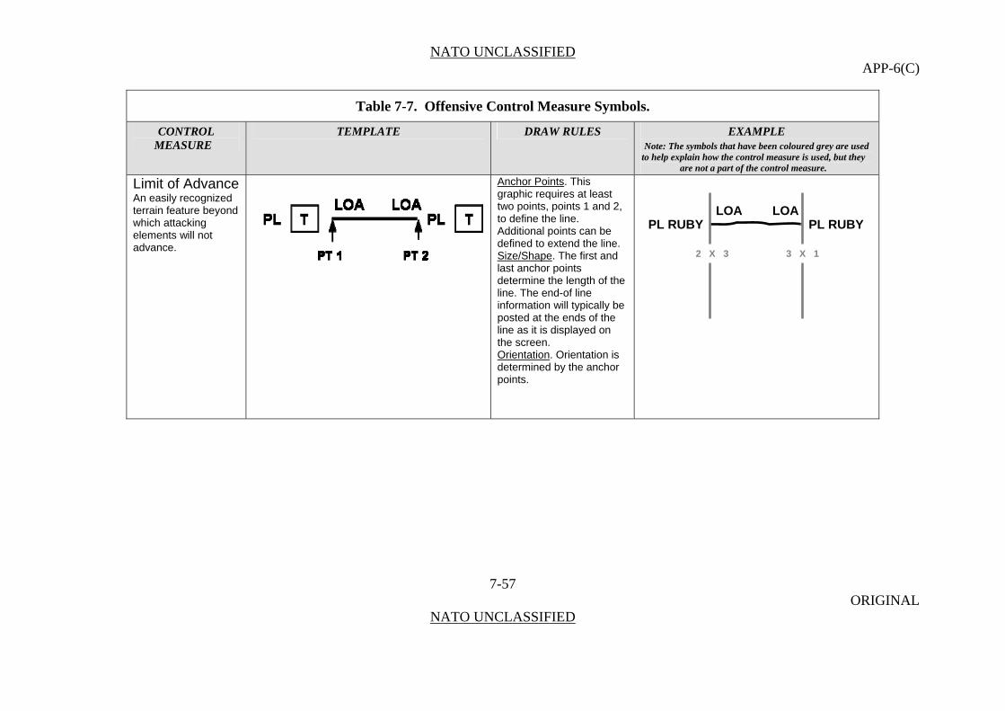
NATO UNCLASSIFIED APP-6(C)
Table 7-7. Offensive Control Measure Symbols.
CONTROL TEMPLATE DRAW RULES EXAMPLE MEASURE Note: The symbols that have been coloured grey are used
to help explain how the control measure is used, but they are not a part of the control measure.
Limit of Advance Anchor Points. This graphic requires at least two points, points 1 and 2, to define the line. Additional points can be defined to extend the line.
7-57 ORIGINAL
NATO UNCLASSIFIED
An easily recognized terrain feature beyond which attacking elements will not advance.
Size/Shape. The first and last anchor points determine the length of the line. The end-of line information will typically be posted at the ends of the line as it is displayed on the screen. Orientation. Orientation is determined by the anchor points.
PL RUBYPL RUBY LOA LOA
2 X 3 3 X 1

NATO UNCLASSIFIED APP-6(C)
Table 7-7. Offensive Control Measure Symbols.
CONTROL TEMPLATE DRAW RULES EXAMPLE MEASURE Note: The symbols that have been coloured grey are used
to help explain how the control measure is used, but they are not a part of the control measure.
Line of Departure
7-58 ORIGINAL
NATO UNCLASSIFIED
In land warfare, a line designated to coordinate the departure of attack elements. (AAP-6) In amphibious warfare, a suitably marked offshore coordinating line to assist assault craft to land on designated beaches at scheduled times. (AAP-6)
Line of Departure/Line of Contact The designation of forward friendly positions as the line of departure when opposing forces are in contact.
PL JADEPL JADE LD LD
2 X 3 3 X 1

NATO UNCLASSIFIED APP-6(C)
Table 7-7. Offensive Control Measure Symbols.
CONTROL TEMPLATE DRAW RULES EXAMPLE MEASURE Note: The symbols that have been coloured grey are used
to help explain how the control measure is used, but they are not a part of the control measure.
Probable Line of Deployment
7-59 ORIGINAL
NATO UNCLASSIFIED
A line selected on the ground, usually the last covered and concealed position prior to the objective and forward of the line of departure, where attacking units deploy prior to beginning an assault; it is generally used under conditions of limited visibility.
Areas Assault Position That position between the line of departure and the objective in an attack from which forces assault the objective. Ideally, it is the last covered and concealed position before reaching the objective
Anchor Points. This graphic requires at least three anchor points to define the boundary of the area. Add as many points as necessary to accurately reflect the area’s size and shape. Size/Shape. Determined by the anchor points. The information field should be moveable within the area. Orientation. Not applicable.
TASLT ASLT DANUBE
PL PEARLPL PEARL PLD PLD
2 X 3 3 X 1
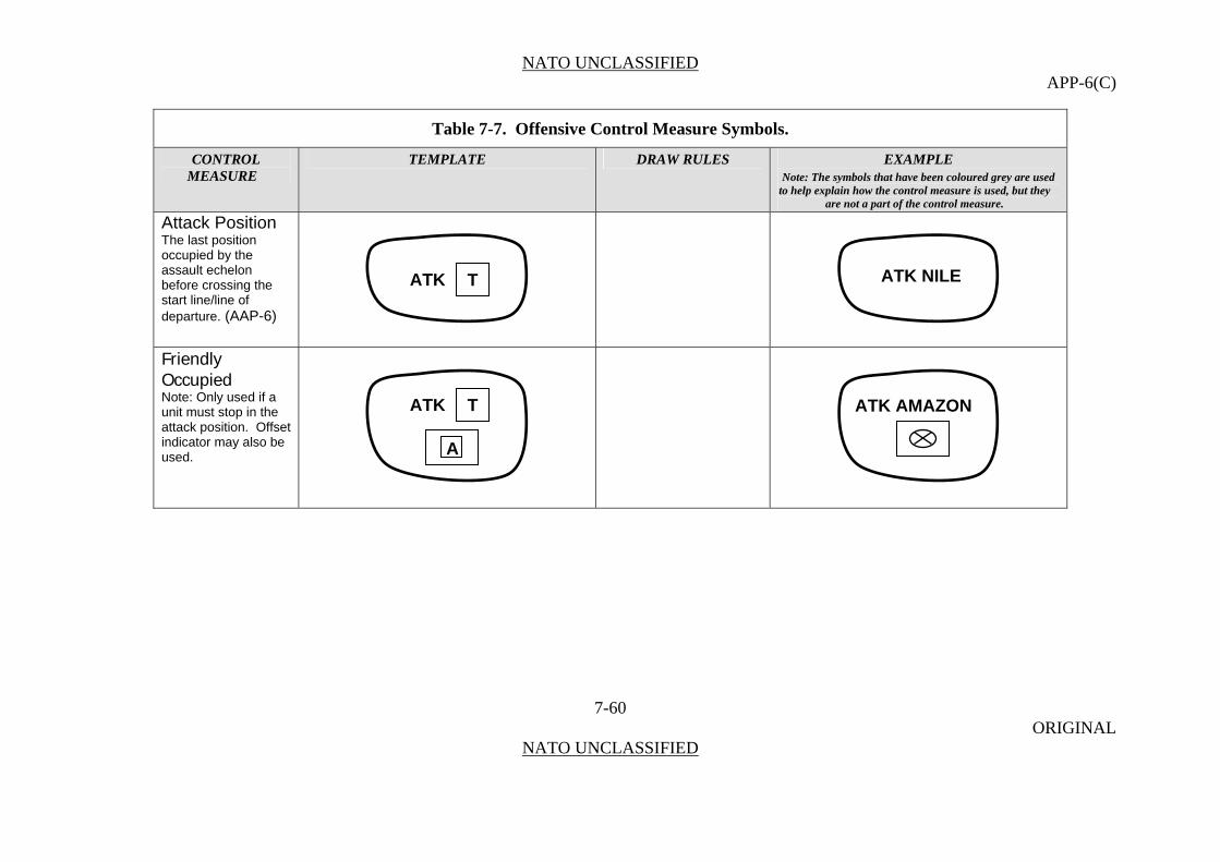
NATO UNCLASSIFIED APP-6(C)
Table 7-7. Offensive Control Measure Symbols.
CONTROL TEMPLATE DRAW RULES EXAMPLE MEASURE Note: The symbols that have been coloured grey are used
to help explain how the control measure is used, but they are not a part of the control measure.
Attack Position
7-60 ORIGINAL
NATO UNCLASSIFIED
The last position occupied by the assault echelon before crossing the start line/line of departure. (AAP-6)
Friendly Occupied Note: Only used if a unit must stop in the attack position. Offset indicator may also be used.
TATK
TATK
A
ATK NILE
ATK AMAZON
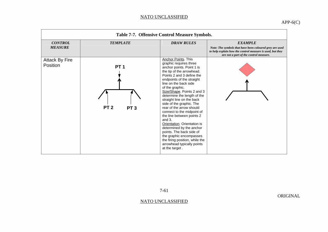
NATO UNCLASSIFIED APP-6(C)
Table 7-7. Offensive Control Measure Symbols.
CONTROL TEMPLATE DRAW RULES EXAMPLE MEASURE Note: The symbols that have been coloured grey are used
to help explain how the control measure is used, but they are not a part of the control measure.
Attack By Fire Position
Anchor Points. This graphic requires three anchor points. Point 1 is the tip of the arrowhead. Points 2 and 3 define the endpoints of the straight line on the back side
7-61 ORIGINAL
NATO UNCLASSIFIED
of the graphic. Size/Shape. Points 2 and 3 determine the length of the straight line on the back side of the graphic. The rear of the arrow should connect to the midpoint of the line between points 2 and 3. Orientation. Orientation is determined by the anchor points. The back side of the graphic encompasses the firing position, while the arrowhead typically points at the target .
PT 1
PT 2 PT 3

NATO UNCLASSIFIED APP-6(C)
Table 7-7. Offensive Control Measure Symbols.
CONTROL TEMPLATE DRAW RULES EXAMPLE MEASURE Note: The symbols that have been coloured grey are used
to help explain how the control measure is used, but they are not a part of the control measure.
Support by Fire Position
Anchor Points. This graphic requires four anchor points. Points 1 and 2 define the endpoints of the straight line on the back side of the graphic. Points 3 and 4 define the tips of the arrowheads.
7-62 ORIGINAL
NATO UNCLASSIFIED
Size/Shape. Points 1 and 2 determine the length of the straight line on the back side of the graphic. The rear of the arrows should connect to points 1 and 2. Orientation. Orientation is determined by the anchor points. The back side of the graphic encompasses the firing position, while the arrowheads typically indicate the arc of coverage that the firing position is meant to support.
PT 3 PT 4
PT 1 PT 2
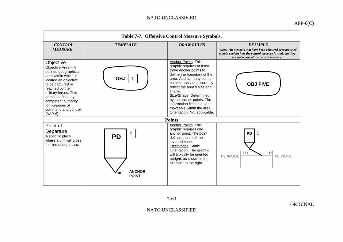
NATO UNCLASSIFIED APP-6(C)
Table 7-7. Offensive Control Measure Symbols.
CONTROL TEMPLATE DRAW RULES EXAMPLE MEASURE Note: The symbols that have been coloured grey are used
to help explain how the control measure is used, but they are not a part of the control measure.
Objective Anchor Points. This graphic requires at least three anchor points to define the boundary of the area. Add as many points as necessary to accurately reflect the area’s size and shape.
Objective Area – A defined geographical area within which is located an objective to be captured or reached by the military forces. This area is defined by competent authority for purposes of command and control. (AAP-6)
7-63 ORIGINAL
NATO UNCLASSIFIED
Size/Shape. Determined by the anchor points. The information field should be moveable within the area. Orientation. Not applicable.
Points Point of Departure A specific place where a unit will cross the line of departure.
Anchor Points. This graphic requires one anchor point. The point defines the tip of the inverted cone. Size/Shape. Static. Orientation. The graphic will typically be oriented upright, as shown in the example to the right.
OBJ TOBJ FIVE
TPD
ANCHORPOINT
1PD
LD LD PL WOOL PL WOOL
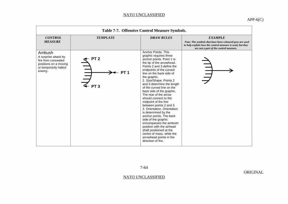
NATO UNCLASSIFIED APP-6(C)
Table 7-7. Offensive Control Measure Symbols.
CONTROL TEMPLATE DRAW RULES EXAMPLE MEASURE Note: The symbols that have been coloured grey are used
to help explain how the control measure is used, but they are not a part of the control measure.
Ambush Anchor Points. This graphic requires three anchor points. Point 1 is the tip of the arrowhead. Points 2 and 3 define the endpoints of the curved line on the back side of
7-64 ORIGINAL
NATO UNCLASSIFIED
A surprise attack by fire from concealed positions on a moving or temporarily halted enemy.
the graphic. 2. Size/Shape. Points 2 and 3 determine the length of the curved line on the back side of the graphic. The rear of the arrow should connect to the midpoint of the line between points 2 and 3. 3. Orientation. Orientation is determined by the anchor points. The back side of the graphic encompasses the ambush position with the airhead shaft positioned at the centre of mass, while the arrowhead points in the direction of fire.
PT 2
PT 1
PT 3
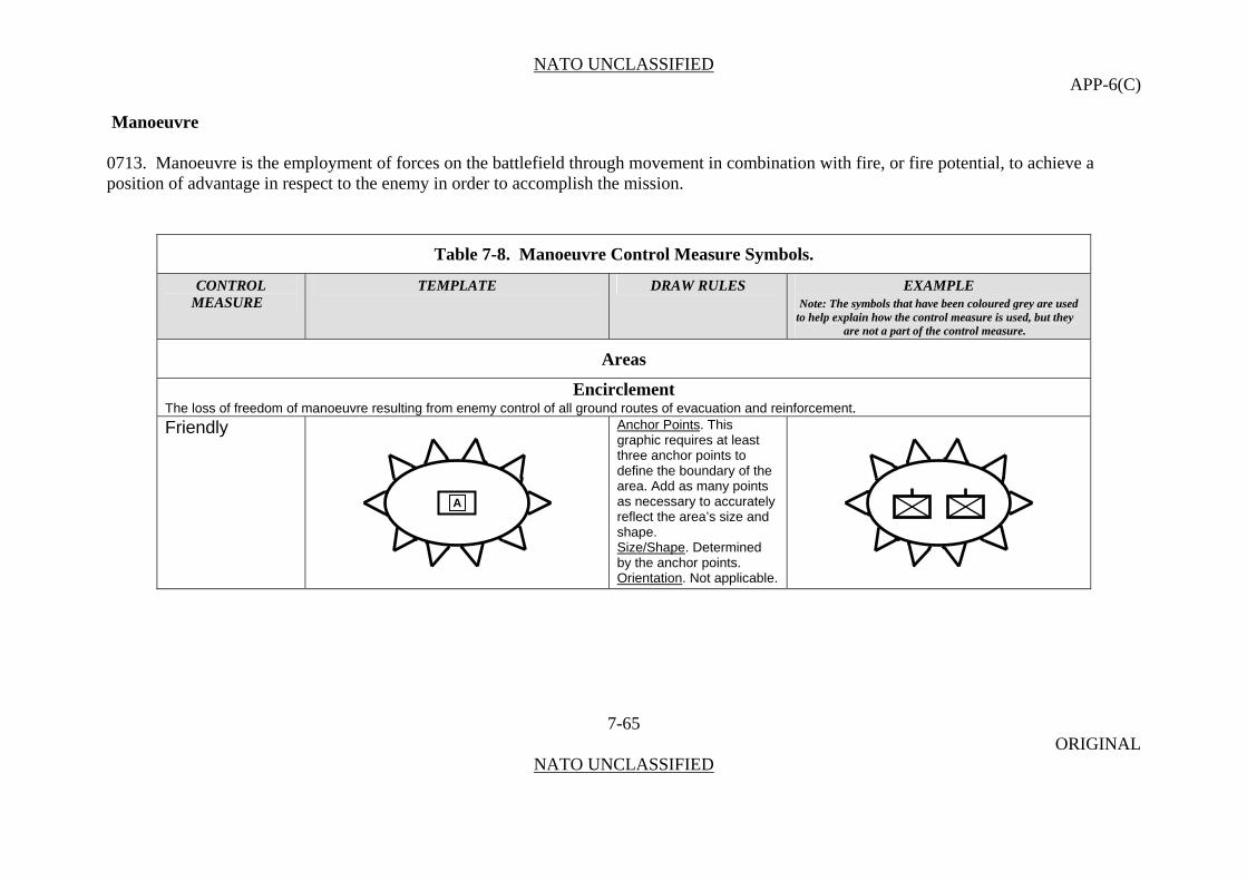
NATO UNCLASSIFIED APP-6(C)
Manoeuvre 0713. Manoeuvre is the employment of forces on the battlefield through movement in combination with fire, or fire potential, to achieve a position of advantage in respect to the enemy in order to accomplish the mission.
Table 7-8. Manoeuvre Control Measure Symbols.
CONTROL TEMPLATE DRAW RULES EXAMPLE MEASURE Note: The symbols that have been coloured grey are used
to help explain how the control measure is used, but they are not a part of the control measure.
Areas
Encirclement The loss of freedom of manoeuvre resulting from enemy control of all ground routes of evacuation and reinforcement. Friendly Anchor Points. This
graphic requires at least three anchor points to define the boundary of the area. Add as many points as necessary to accurately reflect the area’s size and shape.
7-65 ORIGINAL
NATO UNCLASSIFIED
Size/Shape. Determined by the anchor points. Orientation. Not applicable.
A
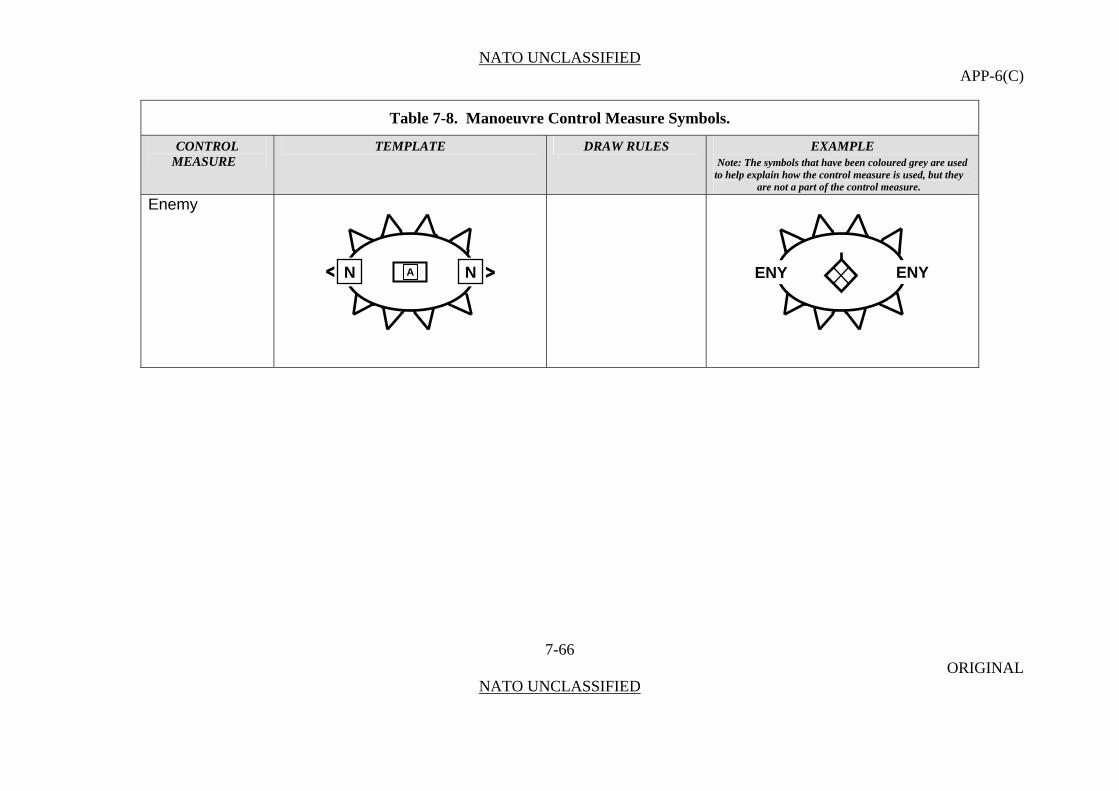
NATO UNCLASSIFIED APP-6(C)
Table 7-8. Manoeuvre Control Measure Symbols.
CONTROL TEMPLATE DRAW RULES EXAMPLE MEASURE Note: The symbols that have been coloured grey are used
to help explain how the control measure is used, but they are not a part of the control measure.
Enemy
7-66 ORIGINAL
NATO UNCLASSIFIED
AN N ENYENY

NATO UNCLASSIFIED APP-6(C)
Table 7-8. Manoeuvre Control Measure Symbols.
CONTROL TEMPLATE DRAW RULES EXAMPLE MEASURE Note: The symbols that have been coloured grey are used
to help explain how the control measure is used, but they are not a part of the control measure.
Lines Airhead Line Anchor Points. This
graphic requires at least three anchor points to define the boundary of the area. Add as many points as necessary to accurately reflect the area’s size and shape.
A line denoting the limits of the objective area for an airborne assault.
7-67 ORIGINAL
NATO UNCLASSIFIED
Airhead A designated area in a hostile or threatened territory which, when seized and held, ensures the continuous air landing of troops and materiel and provides the manoeuvre space necessary for projected operations. Normally it is the area seized in the assault phase of an airborne operation. (AAP-6)
Size/Shape. Determined by the anchor points. Orientation. Not applicable.
OBJOBJ 3
AIRHEAD LINE
1
OBJ4OBJ
2
B D
C
A C
D
A
B
DZRED
AIRHEAD LINE
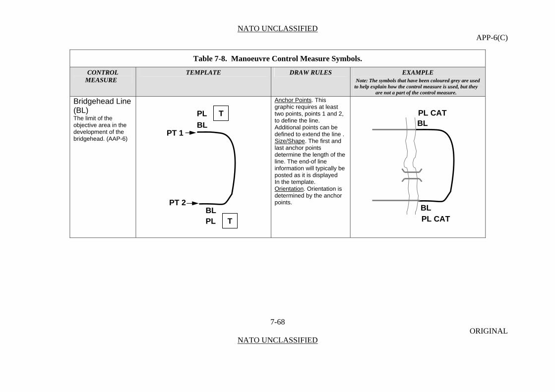
NATO UNCLASSIFIED APP-6(C)
Table 7-8. Manoeuvre Control Measure Symbols.
CONTROL TEMPLATE DRAW RULES EXAMPLE MEASURE Note: The symbols that have been coloured grey are used
to help explain how the control measure is used, but they are not a part of the control measure.
Bridgehead Line (BL)
Anchor Points. This graphic requires at least two points, points 1 and 2, to define the line. Additional points can be defined to extend the line .
7-68 ORIGINAL
NATO UNCLASSIFIED
The limit of the objective area in the development of the bridgehead. (AAP-6)
Size/Shape. The first and last anchor points determine the length of the line. The end-of line information will typically be posted as it is displayed In the template. Orientation. Orientation is determined by the anchor points.
BLPL CATTPL
BLPL CAT
BL
BL
PT 1
PT 2
TPL

NATO UNCLASSIFIED APP-6(C)
Table 7-8. Manoeuvre Control Measure Symbols.
CONTROL TEMPLATE DRAW RULES EXAMPLE MEASURE Note: The symbols that have been coloured grey are used
to help explain how the control measure is used, but they are not a part of the control measure.
Holding Line (HL)
7-69 ORIGINAL
NATO UNCLASSIFIED
In retrograde river crossing operations, the outer limit of the area established between the enemy and the water obstacle to preclude direct and observed indirect fires into the crossings.
HL
PL DOG
HL
PL DOG
XX
X
PT 2 PT 1
HL HL T TPL PL

NATO UNCLASSIFIED APP-6(C)
Table 7-8. Manoeuvre Control Measure Symbols.
CONTROL TEMPLATE DRAW RULES EXAMPLE MEASURE Note: The symbols that have been coloured grey are used
to help explain how the control measure is used, but they are not a part of the control measure.
Release Line
7-70 ORIGINAL
NATO UNCLASSIFIED
Phase line used in river crossing operations that delineates a change in the headquarters controlling movement.
HL
PT 2 PT 1
PL T PL TRL RL PL WIND
HL
PL WIND
XXX
HL
HLPL RAIN PL RAIN
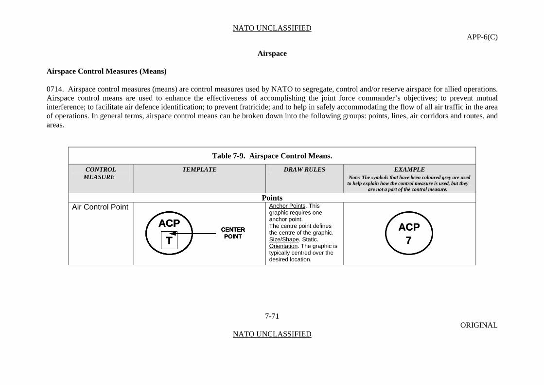
NATO UNCLASSIFIED APP-6(C)
Airspace
Airspace Control Measures (Means)
0714. Airspace control measures (means) are control measures used by NATO to segregate, control and/or reserve airspace for allied operations. Airspace control means are used to enhance the effectiveness of accomplishing the joint force commander’s objectives; to prevent mutual interference; to facilitate air defence identification; to prevent fratricide; and to help in safely accommodating the flow of all air traffic in the area of operations. In general terms, airspace control means can be broken down into the following groups: points, lines, air corridors and routes, and areas.
Table 7-9. Airspace Control Means.
CONTROL TEMPLATE DRAW RULES EXAMPLE MEASURE Note: The symbols that have been coloured grey are used
to help explain how the control measure is used, but they are not a part of the control measure.
Points Air Control Point Anchor Points. This
graphic requires one anchor point. ACP
TCENTER POINT
ACP
T
ACP
TCENTER POINT
CENTER POINT
ACP7
ACP7
The centre point defines the centre of the graphic. Size/Shape. Static. Orientation
7-71 ORIGINAL
NATO UNCLASSIFIED
. The graphic is typically centred over the desired location.
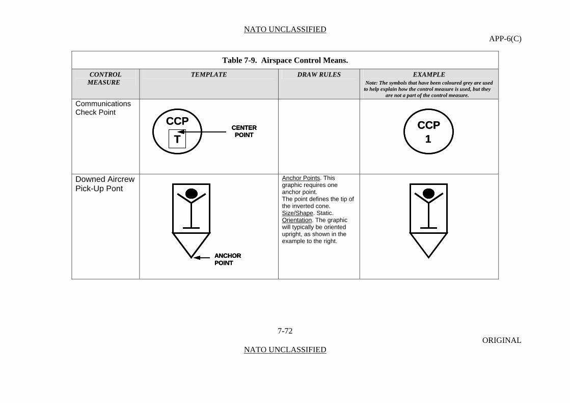
NATO UNCLASSIFIED APP-6(C)
Table 7-9. Airspace Control Means.
CONTROL TEMPLATE DRAW RULES EXAMPLE MEASURE Note: The symbols that have been coloured grey are used
to help explain how the control measure is used, but they are not a part of the control measure.
Communications Check Point
CCP
TCENTER POINT
CCP
TCENTER POINT
CENTER POINT
CCP1
CCP1
Downed Aircrew Pick-Up Pont
Anchor Points. This graphic requires one anchor point.
ANCHORPOINTANCHORPOINTANCHORPOINT
The point defines the tip of the inverted cone. Size/Shape. Static. Orientation. The graphic will typically be oriented upright, as shown in the example to the right.
7-72 ORIGINAL
NATO UNCLASSIFIED
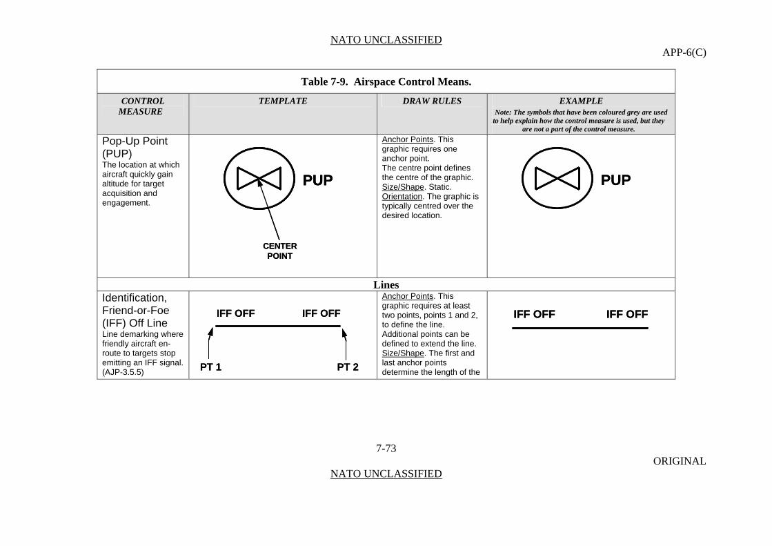
NATO UNCLASSIFIED APP-6(C)
Table 7-9. Airspace Control Means.
CONTROL TEMPLATE DRAW RULES EXAMPLE MEASURE Note: The symbols that have been coloured grey are used
to help explain how the control measure is used, but they are not a part of the control measure.
Pop-Up Point (PUP)
Anchor Points. This graphic requires one anchor point.
PUP
CENTER POINT
PUP PUP
CENTER POINT
PUP PUP The location at which aircraft quickly gain altitude for target acquisition and engagement.
The centre point defines the centre of the graphic. Size/Shape. Static. Orientation
7-73 ORIGINAL
NATO UNCLASSIFIED
. The graphic is typically centred over the desired location.
Lines Identification, Friend-or-Foe (IFF) Off Line
Anchor Points. This graphic requires at least two points, points 1 and 2, to define the line. Additional points can be defined to extend the line.
IFF OFFIFF OFF
PT 2PT 1
IFF OFFIFF OFF
PT 2PT 1
IFF OFFIFF OFF IFF OFFIFF OFF
Line demarking where friendly aircraft en-route to targets stop emitting an IFF signal. (AJP-3.5.5)
Size/Shape. The first and last anchor points determine the length of the

NATO UNCLASSIFIED APP-6(C)
Table 7-9. Airspace Control Means.
CONTROL TEMPLATE DRAW RULES EXAMPLE MEASURE Note: The symbols that have been coloured grey are used
to help explain how the control measure is used, but they are not a part of the control measure.
Identification, Friend-or-Foe (IFF) On Line
line. Orientation
7-74 ORIGINAL
NATO UNCLASSIFIED
Line demarking where friendly aircraft returning to friendly territory start emitting an IFF signal. (AJP-3.5.5)
IFF ONIFF ON
PT 2PT 1
IFF ONIFF ON
PT 2PT 1
. Orientation is determined by the anchor points.
IFF ONIFF ON IFF ONIFF ON

NATO UNCLASSIFIED APP-6(C)
Table 7-9. Airspace Control Means.
CONTROL TEMPLATE DRAW RULES EXAMPLE MEASURE Note: The symbols that have been coloured grey are used
to help explain how the control measure is used, but they are not a part of the control measure.
Corridors (Areas) Air Corridor Anchor Points. This graphic
may contain multiple segments. Each segment requires 2 anchor points. Point numbers that define the trace of the segment are sequential beginning with point 1, in increments of 1, up to a max of 99 points. Each anchor point defines the endpoint of a segment’s centreline. The anchor points are Air Control Points (ACP), Communications Checkpoints (CCP) or both.
A restricted air route of travel specified for use by friendly aircraft and established for the purpose of preventing friendly aircraft from being fired on by friendly forces. (AAP-6)
PT 2PT 1
NAME:
WIDTH:
MIN ALT:
MAX ALT:
DTG START:
DTG END:
T
X
H
X1
W
W1
TAC
PT 2PT 2PT 1PT 1
NAME:
WIDTH:
MIN ALT:
MAX ALT:
DTG START:
DTG END:
T
X
H
X1
W
W1
NAME:
WIDTH:
MIN ALT:
MAX ALT:
DTG START:
DTG END:
T
X
H
X1
W
W1
TT
XX
HH
X1X1
WW
W1W1
TAC TAC TAC ACP2
ACP1 AC GOLD
NAME: GOLD
WIDTH: 400M
MIN ALT: 500M
MAX ALT: 4000M
DTG START: 240700ZMAY08
DTG END: 280700ZMAY08
ACP2
ACP1 AC GOLD ACP
2ACP
2ACP
1ACP
1 AC GOLD
NAME: GOLD
WIDTH: 400M
MIN ALT: 500M
MAX ALT: 4000M
DTG START: 240700ZMAY08
DTG END: 280700ZMAY08
Size/Shape. Points 1 and 2 determine the length of a segment. The information field inside each segment should be moveable and scalable within each segment. The information box outside the graphic should be placed between points 1 and 2 in such a way it does not obscure the graphic.
Orientation. The anchor points determine orientation.
7-75 ORIGINAL
NATO UNCLASSIFIED
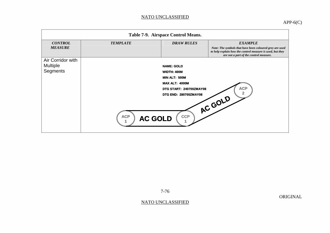
NATO UNCLASSIFIED APP-6(C)
Table 7-9. Airspace Control Means.
CONTROL TEMPLATE DRAW RULES EXAMPLE MEASURE Note: The symbols that have been coloured grey are used
to help explain how the control measure is used, but they are not a part of the control measure.
Air Corridor with Multiple Segments
CCP1
ACP1 AC GOLD
ACP2
AC GOLD
NAME: GOLD
WIDTH: 400M
MIN ALT: 500M
MAX ALT: 4000M
DTG START: 240700ZMAY08
DTG END: 280700ZMAY08
CCP1
ACP1 AC GOLD
ACP2
AC GOLD
CCP1
ACP1
ACP1 AC GOLD
ACP2
ACP2
AC GOLD
NAME: GOLD
WIDTH: 400M
MIN ALT: 500M
MAX ALT: 4000M
DTG START: 240700ZMAY08
DTG END: 280700ZMAY08
7-76 ORIGINAL
NATO UNCLASSIFIED

NATO UNCLASSIFIED APP-6(C)
Table 7-9. Airspace Control Means.
CONTROL TEMPLATE DRAW RULES EXAMPLE MEASURE Note: The symbols that have been coloured grey are used
to help explain how the control measure is used, but they are not a part of the control measure.
Low-Level Transit Route
PT 2PT 1
NAME:
WIDTH:
MIN ALT:
MAX ALT:
DTG START:
DTG END:
T
X
H
X1
W
W1
TLLTR
PT 2PT 2PT 1PT 1
NAME:
WIDTH:
MIN ALT:
MAX ALT:
DTG START:
DTG END:
T
X
H
X1
W
W1
NAME:
WIDTH:
MIN ALT:
MAX ALT:
DTG START:
DTG END:
T
X
H
X1
W
W1
TT
XX
HH
X1X1
WW
W1W1
TLLTR TLLTR ACP2
ACP1 LLTR COBRA
NAME: COBRA
WIDTH: 100M
MIN ALT: 50M
MAX ALT: 1000M
DTG START: 090700ZOCT08
DTG END: 091700ZOCT08
ACP2
ACP2
ACP1
ACP1 LLTR COBRA
NAME: COBRA
WIDTH: 100M
MIN ALT: 50M
MAX ALT: 1000M
DTG START: 090700ZOCT08
DTG END: 091700ZOCT08
A temporary corridor of defined dimensions established in the forward area to minimize the risk to friendly aircraft from friendly air defences or surface forces.
7-77 ORIGINAL
NATO UNCLASSIFIED
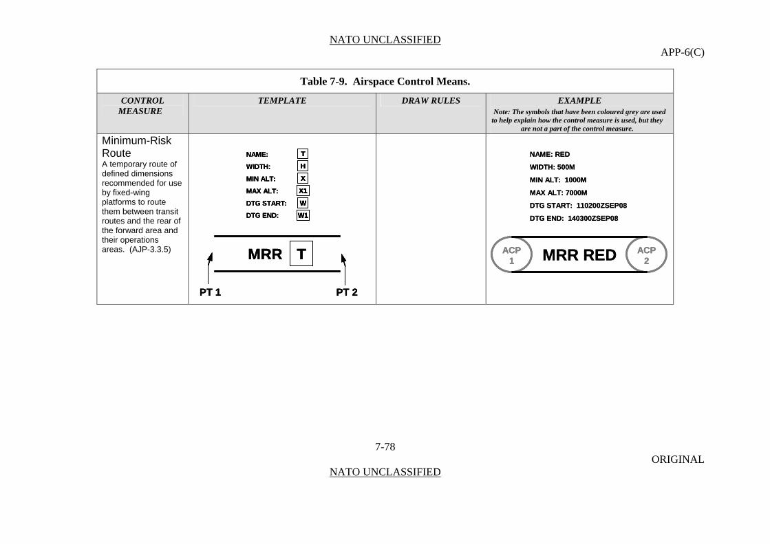
NATO UNCLASSIFIED APP-6(C)
Table 7-9. Airspace Control Means.
CONTROL TEMPLATE DRAW RULES EXAMPLE MEASURE Note: The symbols that have been coloured grey are used
to help explain how the control measure is used, but they are not a part of the control measure.
Minimum-Risk Route
PT 2PT 1
NAME:
WIDTH:
MIN ALT:
MAX ALT:
DTG START:
DTG END:
T
X
H
X1
W
W1
TMRR
PT 2PT 2PT 1PT 1
NAME:
WIDTH:
MIN ALT:
MAX ALT:
DTG START:
DTG END:
T
X
H
X1
W
W1
NAME:
WIDTH:
MIN ALT:
MAX ALT:
DTG START:
DTG END:
T
X
H
X1
W
W1
TT
XX
HH
X1X1
WW
W1W1
TMRR TMRR ACP2
ACP1 MRR RED
NAME: RED
WIDTH: 500M
MIN ALT: 1000M
MAX ALT: 7000M
DTG START: 110200ZSEP08
DTG END: 140300ZSEP08
ACP2
ACP2
ACP1
ACP1 MRR RED
NAME: RED
WIDTH: 500M
MIN ALT: 1000M
MAX ALT: 7000M
DTG START: 110200ZSEP08
DTG END: 140300ZSEP08
A temporary route of defined dimensions recommended for use by fixed-wing platforms to route them between transit routes and the rear of the forward area and their operations areas. (AJP-3.3.5)
7-78 ORIGINAL
NATO UNCLASSIFIED
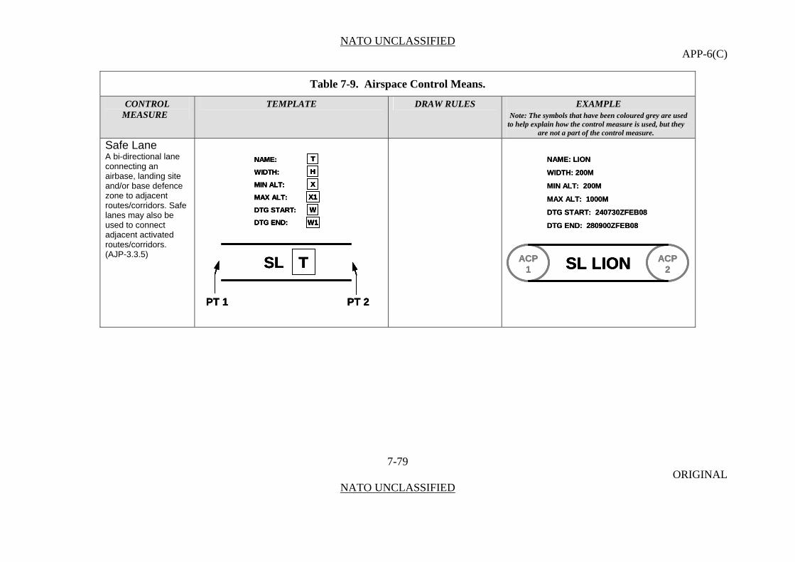
NATO UNCLASSIFIED APP-6(C)
Table 7-9. Airspace Control Means.
CONTROL TEMPLATE DRAW RULES EXAMPLE MEASURE Note: The symbols that have been coloured grey are used
to help explain how the control measure is used, but they are not a part of the control measure.
Safe Lane
A bi-directional lane connecting an airbase, landing site and/or base defence zone to adjacent routes/corridors. Safe lanes may also be used to connect adjacent activated routes/corridors. (AJP-3.3.5)
PT 2PT 1
NAME:
WIDTH:
MIN ALT:
MAX ALT:
DTG START:
DTG END:
T
X
H
X1
W
W1
TSL
PT 2PT 2PT 1PT 1
NAME:
WIDTH:
MIN ALT:
MAX ALT:
DTG START:
DTG END:
T
X
H
X1
W
W1
NAME:
WIDTH:
MIN ALT:
MAX ALT:
DTG START:
DTG END:
T
X
H
X1
W
W1
TT
XX
HH
X1X1
WW
W1W1
TSL TSL ACP2
ACP1 SL LION
NAME: LION
WIDTH: 200M
MIN ALT: 200M
MAX ALT: 1000M
DTG START: 240730ZFEB08
DTG END: 280900ZFEB08
ACP2
ACP2
ACP1
ACP1 SL LIONSL LION
NAME: LION
WIDTH: 200M
MIN ALT: 200M
MAX ALT: 1000M
DTG START: 240730ZFEB08
DTG END: 280900ZFEB08
7-79 ORIGINAL
NATO UNCLASSIFIED
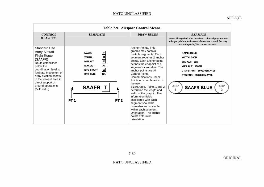
NATO UNCLASSIFIED APP-6(C)
Table 7-9. Airspace Control Means.
CONTROL TEMPLATE DRAW RULES EXAMPLE MEASURE Note: The symbols that have been coloured grey are used
to help explain how the control measure is used, but they are not a part of the control measure.
Standard Use Army Aircraft Flight Route (SAAFR)
Anchor Points. This graphic may contain multiple segments. Each segment requires 2 anchor points. Each anchor point defines the endpoint of a segment’s centreline. The anchor points are Air Control Points, Communications Check Points or a combination of the two.
PT 2PT 1
NAME:
WIDTH:
MIN ALT:
MAX ALT:
DTG START:
DTG END:
T
X
H
X1
W
W1
TSAAFR
PT 2PT 2PT 1PT 1
NAME:
WIDTH:
MIN ALT:
MAX ALT:
DTG START:
DTG END:
T
X
H
X1
W
W1
NAME:
WIDTH:
MIN ALT:
MAX ALT:
DTG START:
DTG END:
T
X
H
X1
W
W1
TT
XX
HH
X1X1
WW
W1W1
TSAAFR TSAAFR ACP2
ACP1 SAAFR BLUE
NAME: BLUE
WIDTH: 200M
MIN ALT: 50M
MAX ALT: 1000M
DTG START: 260930ZMAY08
DTG END: 280700ZMAY08
ACP2
ACP2
ACP1
ACP1 SAAFR BLUE
NAME: BLUE
WIDTH: 200M
MIN ALT: 50M
MAX ALT: 1000M
DTG START: 260930ZMAY08
DTG END: 280700ZMAY08
Route established below the coordination level to facilitate movement of army aviation assets in the forward area in direct support of ground operations. (AJP-3.3.5)
Size/Shape. Points 1 and 2 determine the length and width of the graphic. The information fields associated with each segment should be moveable and scalable within each segment.
Orientation. The anchor points determine orientation.
7-80 ORIGINAL
NATO UNCLASSIFIED

NATO UNCLASSIFIED APP-6(C)
Table 7-9. Airspace Control Means.
CONTROL TEMPLATE DRAW RULES EXAMPLE MEASURE Note: The symbols that have been coloured grey are used
to help explain how the control measure is used, but they are not a part of the control measure.
Transit Corridors
PT 1
NAME:
WIDTH:
MIN ALT:
MAX ALT:
DTG START:
DTG END:
T
X
H
X1
W
W1
TTC
PT 1PT 1
NAME:
WIDTH:
MIN ALT:
MAX ALT:
DTG START:
DTG END:
T
X
H
X1
W
W1
NAME:
WIDTH:
MIN ALT:
MAX ALT:
DTG START:
DTG END:
T
X
H
X1
W
W1
TT
XX
HH
X1X1
WW
W1W1
TTC TTC TTCACP
2ACP
1 TC KING
NAME: KING
WIDTH: 300M
MIN ALT: 700M
MAX ALT: 2000M
DTG START: 260700ZMAR08
DTG END: 280700ZMAR08
ACP2
ACP1 TC KING ACP
2ACP
2ACP
1ACP
1 TC KING
NAME: KING
WIDTH: 300M
MIN ALT: 700M
MAX ALT: 2000M
DTG START: 260700ZMAR08
DTG END: 280700ZMAR08
Bi-directional and established to route aircraft through air defences, in the rear area where appropriate, with minimum risk.
7-81 ORIGINAL
NATO UNCLASSIFIED
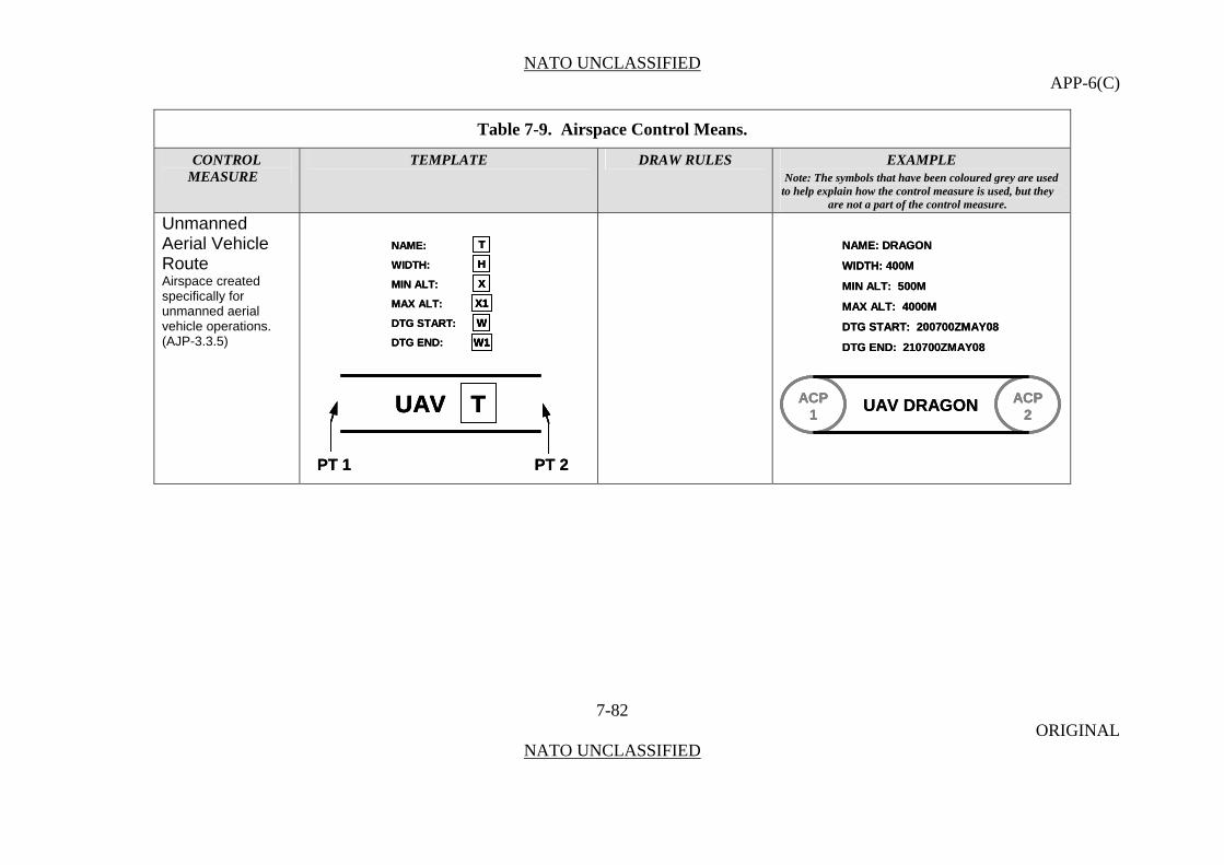
NATO UNCLASSIFIED APP-6(C)
Table 7-9. Airspace Control Means.
CONTROL TEMPLATE DRAW RULES EXAMPLE MEASURE Note: The symbols that have been coloured grey are used
to help explain how the control measure is used, but they are not a part of the control measure.
Unmanned Aerial Vehicle Route
PT 2PT 1
NAME:
WIDTH:
MIN ALT:
MAX ALT:
DTG START:
DTG END:
T
X
H
X1
W
W1
TUAV
PT 2PT 1
NAME:
WIDTH:
MIN ALT:
MAX ALT:
DTG START:
DTG END:
T
X
H
X1
W
W1
TT
XX
HH
X1X1
WW
W1W1
TUAV TUAV ACP2
ACP1
UAV DRAGON
NAME: DRAGON
WIDTH: 400M
MIN ALT: 500M
MAX ALT: 4000M
DTG START: 200700ZMAY08
DTG END: 210700ZMAY08
ACP2
ACP2
ACP1
ACP1
UAV DRAGON
NAME: DRAGON
WIDTH: 400M
MIN ALT: 500M
MAX ALT: 4000M
DTG START: 200700ZMAY08
DTG END: 210700ZMAY08
Airspace created specifically for unmanned aerial vehicle operations. (AJP-3.3.5)
7-82 ORIGINAL
NATO UNCLASSIFIED

NATO UNCLASSIFIED APP-6(C)
Table 7-9. Airspace Control Means.
CONTROL TEMPLATE DRAW RULES EXAMPLE MEASURE Note: The symbols that have been coloured grey are used
to help explain how the control measure is used, but they are not a part of the control measure.
Areas (Zones) Base Defence Zone
Anchor Points. This graphic requires at least three anchor points to define the boundary of the area. Add as many points as necessary to accurately reflect the area’s size and shape.
BDZBDZ BDZBDZA zone established around airbases to enhance the effectiveness of local ground based air defence systems. (AJP 3.3.5)
Size/Shape. Determined by the anchor points. The information fields should be moveable and scalable as a block within the area. Orientation. Not applicable.
High-Density Airspace Control Zone
Anchor Points. This graphic requires at least three anchor points to define the boundary of the area. Add as many points as necessary to accurately reflect the area’s size and shape.
HIDACZ
MIN ALT:
MAX ALT:
TIME FROM:
TIME TO:
T
X
W1
W
X1
HIDACZ
MIN ALT:
MAX ALT:
TIME FROM:
TIME TO:
TT
XX
W1W1
WW
X1X1
HIDACZ
32AADC
MIN ALT: 150000M
MAX ALT: 37000M
TIME FROM: 120700ZMAY08
TIME TO: 140630ZMAY08
HIDACZ
32AADC
MIN ALT: 150000M
MAX ALT: 37000M
TIME FROM: 120700ZMAY08
TIME TO: 140630ZMAY08
Airspace of defined dimensions, designated by the airspace control authority, in which there is a
Size/Shape. Determined by the anchor points. The information fields should be moveable and scalable as a block within the area.
concentrated employment of
numerous and varied Orientation
7-83 ORIGINAL
NATO UNCLASSIFIED
weapons/airspace users. (AAP-6)
. Not applicable.
Restricted Operations Zones
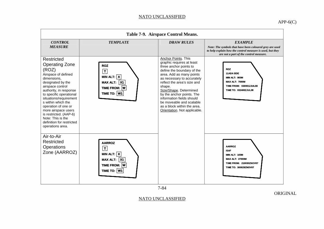
NATO UNCLASSIFIED APP-6(C)
Table 7-9. Airspace Control Means.
CONTROL TEMPLATE DRAW RULES EXAMPLE MEASURE Note: The symbols that have been coloured grey are used
to help explain how the control measure is used, but they are not a part of the control measure.
Restricted Operating Zone (ROZ)
7-84 ORIGINAL
NATO UNCLASSIFIED
Airspace of defined dimensions, designated by the airspace control authority, in response to specific operational situations/requirements within which the operation of one or more airspace users is restricted. (AAP-6) Note: This is the definition for restricted operations area.
ROZ
MIN ALT:
MAX ALT:
TIME FROM:
TIME TO:
T
X
W1
W
X1
ROZ
MIN ALT:
MAX ALT:
TIME FROM:
TIME TO:
TT
XX
W1W1
WW
X1X1
ROZ
11ADA BDE
MIN ALT: 900M
MAX ALT: 7000M
TIME FROM: 030001ZJUL08
TIME TO: 032400ZJUL08
ROZ
11ADA BDE
MIN ALT: 900M
MAX ALT: 7000M
TIME FROM: 030001ZJUL08
TIME TO: 032400ZJUL08
Anchor Points. This graphic requires at least three anchor points to define the boundary of the area. Add as many points as necessary to accurately reflect the area’s size and shape. Size/Shape. Determined by the anchor points. The information fields should be moveable and scalable as a block within the area. Orientation. Not applicable.
Air-to-Air Restricted Operations Zone (AARROZ)
AARROZ
ISAF
MIN ALT: 100M
MAX ALT: 27000M
TIME FROM: 210030ZNOV07
TIME TO: 300029ZNOV07
AARROZ
ISAF
MIN ALT: 100M
MAX ALT: 27000M
TIME FROM: 210030ZNOV07
TIME TO: 300029ZNOV07
AARROZ
MIN ALT:
MAX ALT:
TIME FROM:
TIME TO:
T
X
W1
W
X1
AARROZ
MIN ALT:
MAX ALT:
TIME FROM:
TIME TO:
TT
XX
W1W1
WW
X1X1
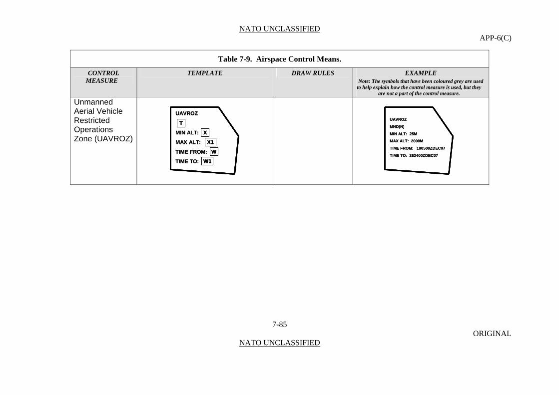
NATO UNCLASSIFIED APP-6(C)
Table 7-9. Airspace Control Means.
CONTROL TEMPLATE DRAW RULES EXAMPLE MEASURE Note: The symbols that have been coloured grey are used
to help explain how the control measure is used, but they are not a part of the control measure.
Unmanned Aerial Vehicle Restricted Operations Zone (UAVROZ)
UAVROZ
MIN ALT:
MAX ALT:
TIME FROM:
TIME TO:
T
X
W1
W
X1
UAVROZ
MIN ALT:
MAX ALT:
TIME FROM:
TIME TO:
TT
XX
W1W1
WW
X1X1
UAVROZ
MND(N)
MIN ALT: 25M
MAX ALT: 2000M
TIME FROM: 190500ZDEC07
TIME TO: 262400ZDEC07
UAVROZ
MND(N)
MIN ALT: 25M
MAX ALT: 2000M
TIME FROM: 190500ZDEC07
TIME TO: 262400ZDEC07
7-85 ORIGINAL
NATO UNCLASSIFIED

NATO UNCLASSIFIED APP-6(C)
Table 7-9. Airspace Control Means.
CONTROL TEMPLATE DRAW RULES EXAMPLE MEASURE Note: The symbols that have been coloured grey are used
to help explain how the control measure is used, but they are not a part of the control measure.
Weapons Engagement Zones Weapon Engagement Zone
7-86 ORIGINAL
NATO UNCLASSIFIED
In air defence, airspace of defined dimensions within which the responsibility for engagement normally rests with a particular weapon system. (AAP-6) Note: Includes FEZ, JEZ, MEZ (LOMEZ and HIMEZ), SHORADEZ.
WEZ
MIN ALT:
MAX ALT:
TIME FROM:
TIME TO:
T
X
W1
W
X1
WEZ
MIN ALT:
MAX ALT:
TIME FROM:
TIME TO:
TT
XX
W1W1
WW
X1X1
WEZ
21 ADA BN
MIN ALT: 100M
MAX ALT: 34000M
TIME FROM: 040030ZJAN08
TIME TO: 040029ZJAN08
WEZ
21 ADA BN
MIN ALT: 100M
MAX ALT: 34000M
TIME FROM: 040030ZJAN08
TIME TO: 040029ZJAN08
Anchor Points. This graphic requires at least three anchor points to define the boundary of the area. Add as many points as necessary to accurately reflect the area’s size and shape. Size/Shape. Determined by the anchor points. The information fields should be moveable and scalable as a block within the area. Orientation. Not applicable.
Fighter Engagement Zone
FEZ
MIN ALT:
MAX ALT:
TIME FROM:
TIME TO:
T
X
W1
W
X1
FEZ
MIN ALT:
MAX ALT:
TIME FROM:
TIME TO:
TT
XX
W1W1
WW
X1X1
FEZ
ATF
MIN ALT: 250M
MAX ALT: 50000M
TIME FROM: 030100ZOCT08
TIME TO: 210100ZDEC08
FEZ
ATF
MIN ALT: 250M
MAX ALT: 50000M
TIME FROM: 030100ZOCT08
TIME TO: 210100ZDEC08
In air defence, airspace of defined dimensions within which the responsibility for engagement normally rests with a particular weapon system. (AAP-6)
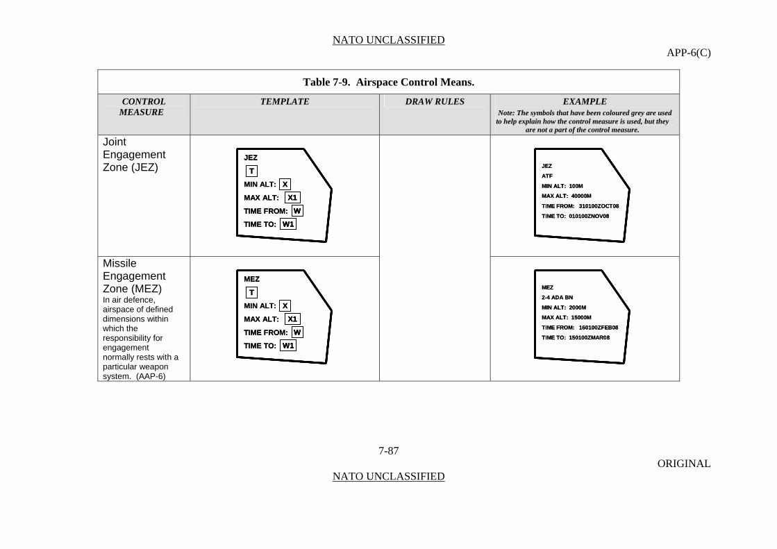
NATO UNCLASSIFIED APP-6(C)
Table 7-9. Airspace Control Means.
CONTROL TEMPLATE DRAW RULES EXAMPLE MEASURE Note: The symbols that have been coloured grey are used
to help explain how the control measure is used, but they are not a part of the control measure.
Joint Engagement Zone (JEZ)
7-87 ORIGINAL
NATO UNCLASSIFIED
JEZ
MIN ALT:
MAX ALT:
TIME FROM:
TIME TO:
T
X
W1
W
X1
JEZ
MIN ALT:
MAX ALT:
TIME FROM:
TIME TO:
TT
XX
W1W1
WW
X1X1
JEZ
ATF
MIN ALT: 100M
MAX ALT: 40000M
TIME FROM: 310100ZOCT08
TIME TO: 010100ZNOV08
JEZ
ATF
MIN ALT: 100M
MAX ALT: 40000M
TIME FROM: 310100ZOCT08
TIME TO: 010100ZNOV08
Missile Engagement Zone (MEZ)
MEZ
MIN ALT:
MAX ALT:
TIME FROM:
TIME TO:
T
X
W1
W
X1
MEZ
MIN ALT:
MAX ALT:
TIME FROM:
TIME TO:
TT
XX
W1W1
WW
X1X1
MEZ
2-4 ADA BN
MIN ALT: 2000M
MAX ALT: 15000M
TIME FROM: 160100ZFEB08
TIME TO: 150100ZMAR08
MEZ
2-4 ADA BN
MIN ALT: 2000M
MAX ALT: 15000M
TIME FROM: 160100ZFEB08
TIME TO: 150100ZMAR08
In air defence, airspace of defined dimensions within which the responsibility for engagement normally rests with a particular weapon system. (AAP-6)

NATO UNCLASSIFIED APP-6(C)
Table 7-9. Airspace Control Means.
CONTROL TEMPLATE DRAW RULES EXAMPLE MEASURE Note: The symbols that have been coloured grey are used
to help explain how the control measure is used, but they are not a part of the control measure.
Low (Altitude) Missile Engagement Zone (LOMEZ)
7-88 ORIGINAL
NATO UNCLASSIFIED
LOMEZ
MIN ALT:
MAX ALT:
TIME FROM:
TIME TO:
T
X
W1
W
X1
LOMEZ
MIN ALT:
MAX ALT:
TIME FROM:
TIME TO:
TT
XX
W1W1
WW
X1X1
LOMEZ
AACC
MIN ALT: 100M
MAX ALT: 2000M
TIME FROM: 070600ZAUG08
TIME TO: 071600ZAUG08
LOMEZ
AACC
MIN ALT: 100M
MAX ALT: 2000M
TIME FROM: 070600ZAUG08
TIME TO: 071600ZAUG08
High (Altitude) HIMEZ
MIN ALT:
MAX ALT:
TIME FROM:
TIME TO:
T
X
W1
W
X1
HIMEZ
MIN ALT:
MAX ALT:
TIME FROM:
TIME TO:
TT
XX
W1W1
WW
X1X1
HIMEZ
AACC
MIN ALT: 20000M
MAX ALT: 50000M
TIME FROM: 070600ZAUG08
TIME TO: 071600ZAUG08
HIMEZ
AACC
MIN ALT: 20000M
MAX ALT: 50000M
TIME FROM: 070600ZAUG08
TIME TO: 071600ZAUG08
Missile Engagement Zone (HIMEZ)
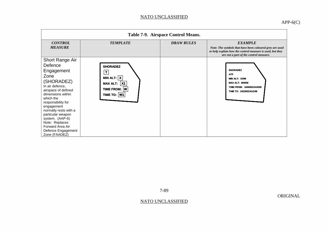
NATO UNCLASSIFIED APP-6(C)
Table 7-9. Airspace Control Means.
CONTROL TEMPLATE DRAW RULES EXAMPLE MEASURE Note: The symbols that have been coloured grey are used
to help explain how the control measure is used, but they are not a part of the control measure.
Short Range Air Defence Engagement Zone (SHORADEZ)
SHORADEZ
ATF
MIN ALT: 100M
MAX ALT: 8000M
TIME FROM: 240600ZAUG08
TIME TO: 242300ZAUG08
SHORADEZ
ATF
MIN ALT: 100M
MAX ALT: 8000M
TIME FROM: 240600ZAUG08
TIME TO: 242300ZAUG08
SHORADEZ
MIN ALT:
MAX ALT:
TIME FROM:
TIME TO:
T
X
W1
W
X1
SHORADEZ
MIN ALT:
MAX ALT:
TIME FROM:
TIME TO:
TT
XX
W1W1
WW
X1X1In air defence, airspace of defined dimensions within which the responsibility for engagement
normally rests with a particular weapon system. (AAP-6) Note: Replaces Forward Area Air Defence Engagement Zone (FAADEZ)
7-89 ORIGINAL
NATO UNCLASSIFIED
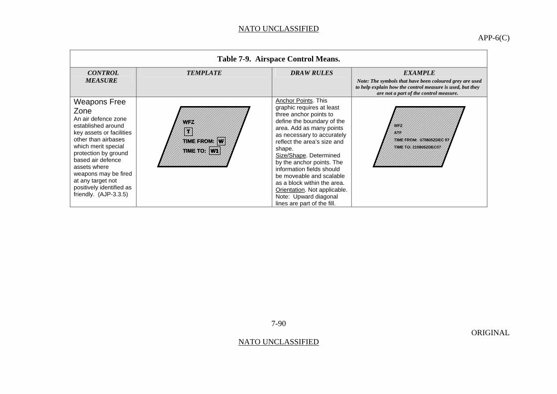
NATO UNCLASSIFIED APP-6(C)
Table 7-9. Airspace Control Means.
CONTROL TEMPLATE DRAW RULES EXAMPLE MEASURE Note: The symbols that have been coloured grey are used
to help explain how the control measure is used, but they are not a part of the control measure.
Weapons Free Zone
Anchor Points. This graphic requires at least three anchor points to define the boundary of the area. Add as many points as necessary to accurately reflect the area’s size and shape.
WFZ
TIME FROM:
TIME TO:
T
W1
W
WFZ
TIME FROM:
TIME TO:
T
W1
W
WFZ
TIME FROM:
TIME TO:
T
W1
W
TT
W1
W
W1W1
WW
WFZ
ATF
TIME FROM: 070805ZDEC 07
TIME TO: 210805ZDEC07
WFZ
ATF
TIME FROM: 070805ZDEC 07
TIME TO: 210805ZDEC07
An air defence zone established around key assets or facilities other than airbases which merit special protection by ground based air defence assets where weapons may be fired at any target not positively identified as friendly. (AJP-3.3.5)
Size/Shape. Determined by the anchor points. The information fields should be moveable and scalable as a block within the area.
Orientation. Not applicable. Note: Upward diagonal lines are part of the fill.
7-90 ORIGINAL
NATO UNCLASSIFIED

NATO UNCLASSIFIED APP-6(C)
Maritime
Maritime Control Measures 0715. Maritime control measures are used by NATO to help the maritime component commander and his subordinate commanders to direct action by establishing responsibilities and to prevent ships, units, or aircraft from impeding one another and to impose necessary coordination. They aid the cooperation among forces without imposing needless restrictions on their freedom of action. In general terms, maritime control measures can be broken down into the following groups: points, lines, and areas.
Table 7-10. Maritime Control Measures.
CONTROL TEMPLATE DRAW RULES EXAMPLE MEASURE Note: The symbols that have been coloured grey are used
to help explain how the control measure is used, but they are not a part of the control measure.
Points
Weapons Aim Point Anchor Points. This
graphic requires one anchor point. The centre point defines the centre of the graphic. Size/Shape. Static. Orientation. The graphic is typically centred over the desired location.
7-91 ORIGINAL
NATO UNCLASSIFIED
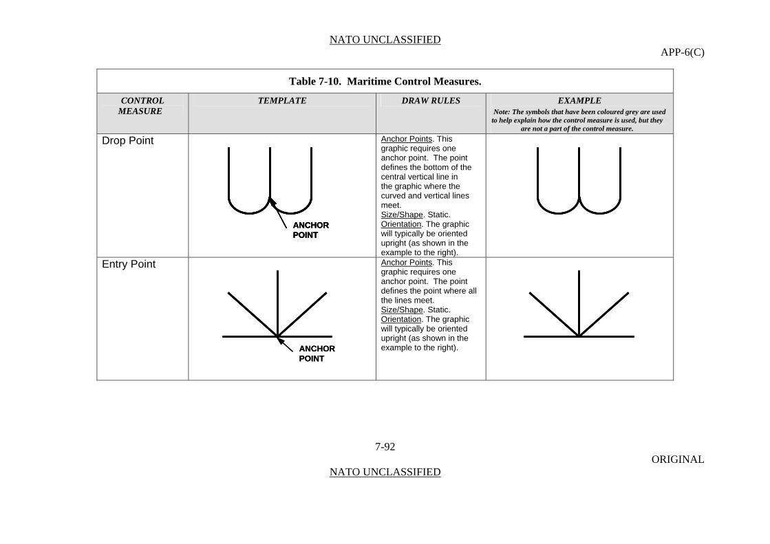
NATO UNCLASSIFIED APP-6(C)
Table 7-10. Maritime Control Measures.
CONTROL TEMPLATE DRAW RULES EXAMPLE MEASURE Note: The symbols that have been coloured grey are used
to help explain how the control measure is used, but they are not a part of the control measure.
Drop Point Anchor Points. This graphic requires one anchor point. The point defines the bottom of the central vertical line in
ANCHORPOINTANCHORPOINTANCHORPOINT
the graphic where the curved and vertical lines meet.
Size/Shape. Static. Orientation. The graphic will typically be oriented upright (as shown in the example to the right).
Entry Point Anchor Points. This graphic requires one anchor point. The point defines the point where all the lines meet.
ANCHORPOINTANCHORPOINT
Size/Shape. Static. Orientation. The graphic will typically be oriented upright (as shown in the example to the right).
7-92 ORIGINAL
NATO UNCLASSIFIED
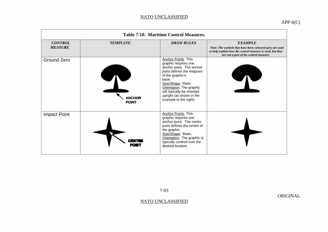
NATO UNCLASSIFIED APP-6(C)
Table 7-10. Maritime Control Measures.
CONTROL TEMPLATE DRAW RULES EXAMPLE MEASURE Note: The symbols that have been coloured grey are used
to help explain how the control measure is used, but they are not a part of the control measure.
Ground Zero Anchor Points. This graphic requires one anchor point. The anchor point defines the midpoint of the graphic’s
ANCHORPOINTANCHORPOINTANCHORPOINT
base. Size/Shape. Static. Orientation. The graphic will typically be oriented upright (as shown in the example to the right).
Impact Point Anchor Points. This graphic requires one anchor point. The centre point defines the centre of the graphic. Size/Shape. Static. Orientation. The graphic is typically centred over the desired location.
7-93 ORIGINAL
NATO UNCLASSIFIED
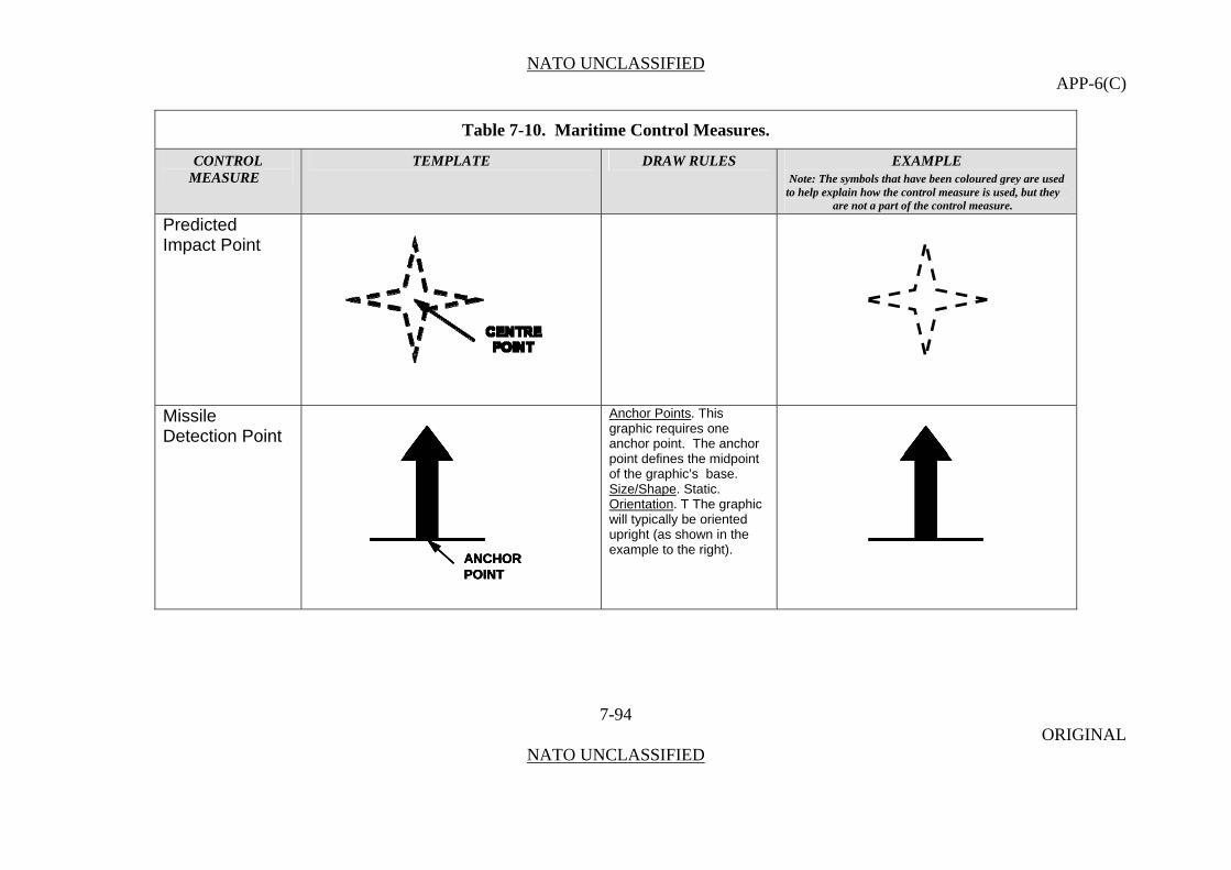
NATO UNCLASSIFIED APP-6(C)
Table 7-10. Maritime Control Measures.
CONTROL TEMPLATE DRAW RULES EXAMPLE MEASURE Note: The symbols that have been coloured grey are used
to help explain how the control measure is used, but they are not a part of the control measure.
Predicted Impact Point
Missile Detection Point
Anchor Points. This graphic requires one anchor point. The anchor point defines the midpoint of the graphic’s base.
ANCHORPOINTANCHORPOINTANCHORPOINT
Size/Shape. Static. Orientation. T The graphic will typically be oriented upright (as shown in the example to the right).
7-94 ORIGINAL
NATO UNCLASSIFIED

NATO UNCLASSIFIED APP-6(C)
Table 7-10. Maritime Control Measures.
CONTROL TEMPLATE DRAW RULES EXAMPLE MEASURE Note: The symbols that have been coloured grey are used
to help explain how the control measure is used, but they are not a part of the control measure.
Sub-Surface Warfare Brief Contact Anchor Points. This
graphic requires one anchor point. The point defines the tip of the arrowhead. B C
ANCHORPOINT
B CB C
ANCHORPOINTANCHORPOINT
B CB CSize/Shape. Static. Orientation. The graphic will typically be oriented upright (as shown in the example to the right).
Datum Anchor Points. This graphic requires one anchor point. The point defines the centre of the graphic. Size/Shape. Static. Orientation. The graphic will be oriented as shown in the example to the right, and will be centred over the datum.
7-95 ORIGINAL
NATO UNCLASSIFIED
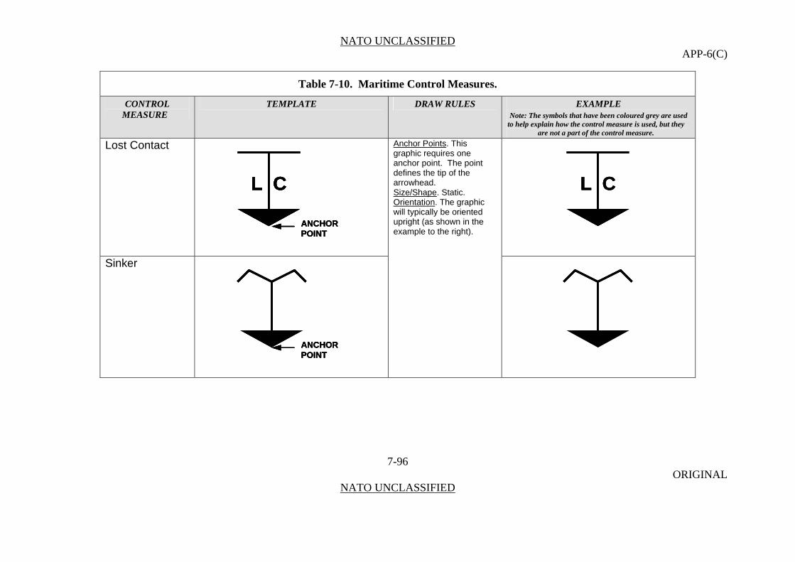
NATO UNCLASSIFIED APP-6(C)
Table 7-10. Maritime Control Measures.
CONTROL TEMPLATE DRAW RULES EXAMPLE MEASURE Note: The symbols that have been coloured grey are used
to help explain how the control measure is used, but they are not a part of the control measure.
Lost Contact
7-96 ORIGINAL
NATO UNCLASSIFIED
L C
ANCHORPOINT
L CL CL C
ANCHORPOINTANCHORPOINT
L CL CL C
Anchor Points. This graphic requires one anchor point. The point defines the tip of the arrowhead. Size/Shape. Static. Orientation. The graphic will typically be oriented upright (as shown in the example to the right).
Sinker
ANCHORPOINTANCHORPOINTANCHORPOINT

NATO UNCLASSIFIED APP-6(C)
Table 7-10. Maritime Control Measures.
CONTROL TEMPLATE DRAW RULES EXAMPLE MEASURE Note: The symbols that have been coloured grey are used
to help explain how the control measure is used, but they are not a part of the control measure.
Fix Acoustic Fix Anchor Points. This
graphic requires one anchor point. The centre point defines the centre of the graphic. Size/Shape. Static. Orientation. The graphic is typically centred over the desired location.
7-97 ORIGINAL
NATO UNCLASSIFIED

NATO UNCLASSIFIED APP-6(C)
Table 7-10. Maritime Control Measures.
CONTROL TEMPLATE DRAW RULES EXAMPLE MEASURE Note: The symbols that have been coloured grey are used
to help explain how the control measure is used, but they are not a part of the control measure.
Electromagnetic Fix
7-98 ORIGINAL
NATO UNCLASSIFIED
Optical Fix
Formation Anchor Points. This graphic requires one
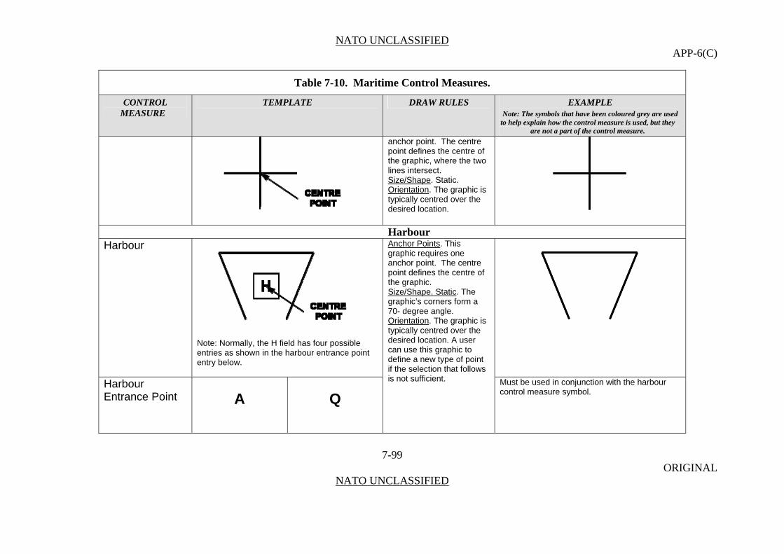
NATO UNCLASSIFIED APP-6(C)
Table 7-10. Maritime Control Measures.
CONTROL TEMPLATE DRAW RULES EXAMPLE MEASURE Note: The symbols that have been coloured grey are used
to help explain how the control measure is used, but they are not a part of the control measure.
anchor point. The centre point defines the centre of the graphic, where the two lines intersect. Size/Shape. Static. Orientation. The graphic is typically centred over the desired location.
Harbour Harbour
7-99 ORIGINAL
NATO UNCLASSIFIED
Note: Normally, the H field has four possible entries as shown in the harbour entrance point entry below.
Anchor Points. This graphic requires one anchor point. The centre point defines the centre of the graphic. Size/Shape. Static. The graphic’s corners form a 70- degree angle. Orientation. The graphic is typically centred over the desired location. A user can use this graphic to define a new type of point if the selection that follows is not sufficient. Harbour
Entrance Point Must be used in conjunction with the harbour
control measure symbol.
A Q
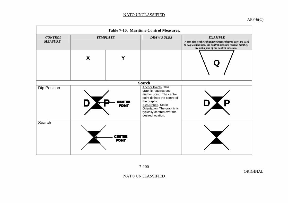
NATO UNCLASSIFIED APP-6(C)
Table 7-10. Maritime Control Measures.
CONTROL TEMPLATE DRAW RULES EXAMPLE MEASURE Note: The symbols that have been coloured grey are used
to help explain how the control measure is used, but they are not a part of the control measure.
X Y
Search Dip Position
7-100 ORIGINAL
NATO UNCLASSIFIED
D PD P
Anchor Points. This graphic requires one anchor point. The centre point defines the centre of the graphic. Size/Shape. Static. Orientation. The graphic is typically centred over the desired location.
Search
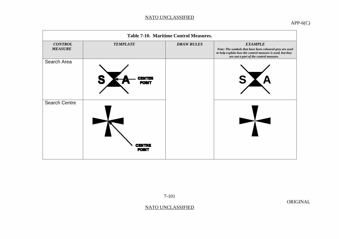
NATO UNCLASSIFIED APP-6(C)
Table 7-10. Maritime Control Measures.
CONTROL TEMPLATE DRAW RULES EXAMPLE MEASURE Note: The symbols that have been coloured grey are used
to help explain how the control measure is used, but they are not a part of the control measure.
Search Area
7-101 ORIGINAL
NATO UNCLASSIFIED
S AS A
Search Centre
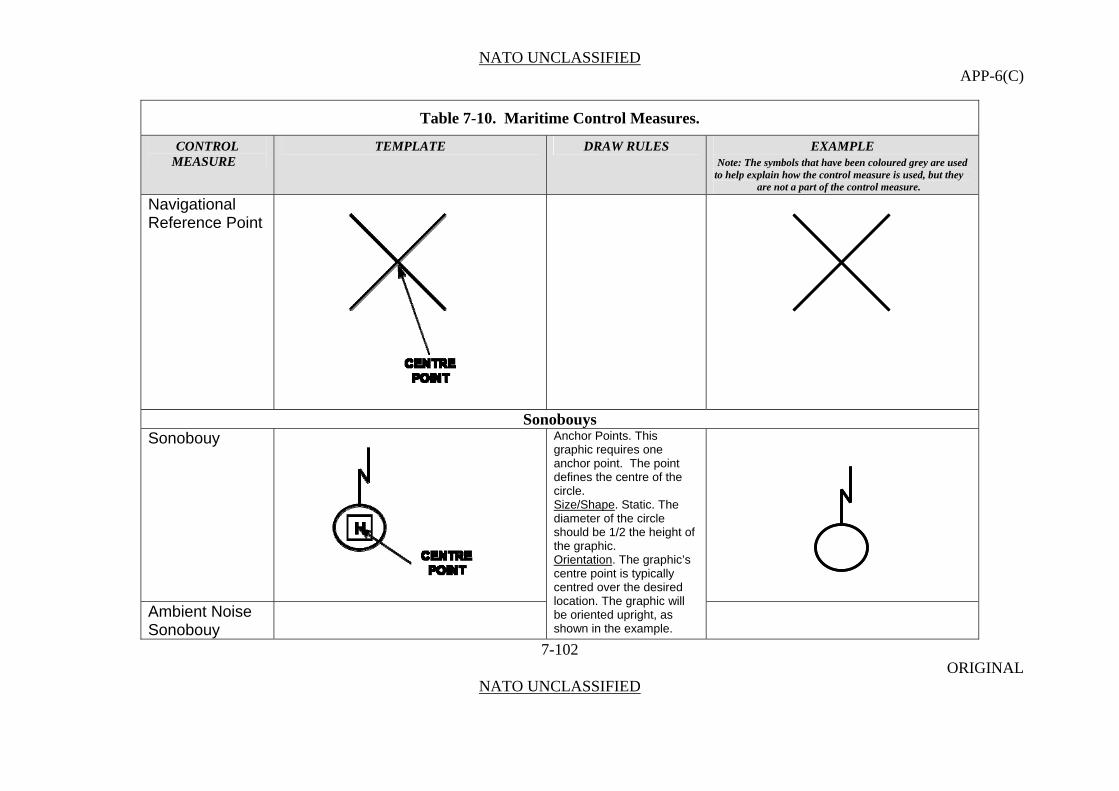
NATO UNCLASSIFIED APP-6(C)
Table 7-10. Maritime Control Measures.
CONTROL TEMPLATE DRAW RULES EXAMPLE MEASURE Note: The symbols that have been coloured grey are used
to help explain how the control measure is used, but they are not a part of the control measure.
Navigational Reference Point
Sonobouys Sonobouy
7-102 ORIGINAL
NATO UNCLASSIFIED
Anchor Points. This graphic requires one anchor point. The point defines the centre of the circle. Size/Shape. Static. The diameter of the circle should be 1/2 the height of the graphic. Orientation. The graphic’s centre point is typically centred over the desired location. The graphic will
Ambient Noise Sonobouy
be oriented upright, as shown in the example.
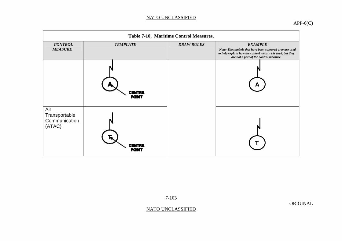
NATO UNCLASSIFIED APP-6(C)
Table 7-10. Maritime Control Measures.
CONTROL TEMPLATE DRAW RULES EXAMPLE MEASURE Note: The symbols that have been coloured grey are used
to help explain how the control measure is used, but they are not a part of the control measure.
AA
7-103 ORIGINAL
NATO UNCLASSIFIED
Air Transportable Communication (ATAC)
TT

NATO UNCLASSIFIED APP-6(C)
Table 7-10. Maritime Control Measures.
CONTROL TEMPLATE DRAW RULES EXAMPLE MEASURE Note: The symbols that have been coloured grey are used
to help explain how the control measure is used, but they are not a part of the control measure.
Bathlythermo-
7-104 ORIGINAL
NATO UNCLASSIFIED
graph Transmitting Sonobouy
BB
Command Active Sonobouy
CC
Directional Command Active Sonobouy System

NATO UNCLASSIFIED APP-6(C)
Table 7-10. Maritime Control Measures.
CONTROL TEMPLATE DRAW RULES EXAMPLE MEASURE Note: The symbols that have been coloured grey are used
to help explain how the control measure is used, but they are not a part of the control measure.
Digital Frequency Analysing and Recording (DIRAR)
7-105 ORIGINAL
NATO UNCLASSIFIED
DD
Expired Sonobouy
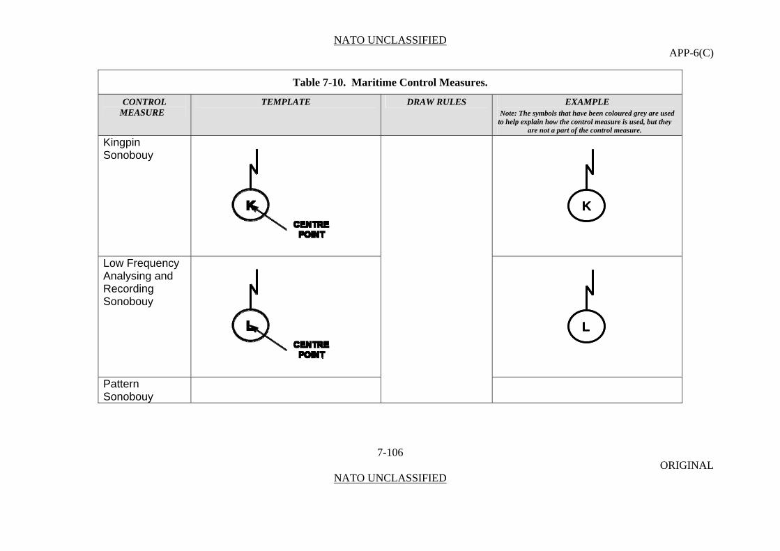
NATO UNCLASSIFIED APP-6(C)
Table 7-10. Maritime Control Measures.
CONTROL TEMPLATE DRAW RULES EXAMPLE MEASURE Note: The symbols that have been coloured grey are used
to help explain how the control measure is used, but they are not a part of the control measure.
Kingpin Sonobouy
7-106 ORIGINAL
NATO UNCLASSIFIED
KK
Low Frequency Analysing and Recording Sonobouy
LL
Pattern Sonobouy

NATO UNCLASSIFIED APP-6(C)
Table 7-10. Maritime Control Measures.
CONTROL TEMPLATE DRAW RULES EXAMPLE MEASURE Note: The symbols that have been coloured grey are used
to help explain how the control measure is used, but they are not a part of the control measure.
PP
7-107 ORIGINAL
NATO UNCLASSIFIED
Range Only Sonobouy
RR

NATO UNCLASSIFIED APP-6(C)
Table 7-10. Maritime Control Measures.
CONTROL TEMPLATE DRAW RULES EXAMPLE MEASURE Note: The symbols that have been coloured grey are used
to help explain how the control measure is used, but they are not a part of the control measure.
Vertical Line Array Directional Frequency Analysis and Recording (DIFAR)
VV
Sonobouy
Reference Points Reference Point Anchor Points. This
graphic requires one anchor point. The centre point defines the centre of the graphic. Size/Shape. Static. Orientation. The graphic is typically centred over the desired location.
7-108 ORIGINAL
NATO UNCLASSIFIED
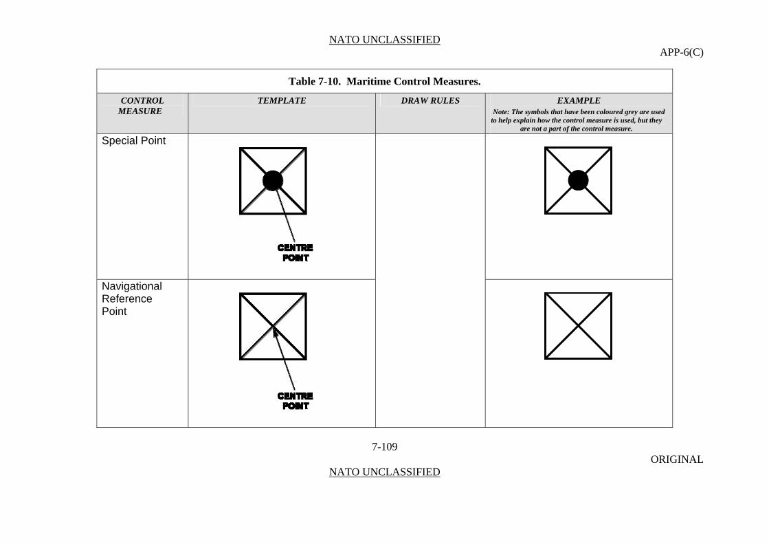
NATO UNCLASSIFIED APP-6(C)
Table 7-10. Maritime Control Measures.
CONTROL TEMPLATE DRAW RULES EXAMPLE MEASURE Note: The symbols that have been coloured grey are used
to help explain how the control measure is used, but they are not a part of the control measure.
Special Point
7-109 ORIGINAL
NATO UNCLASSIFIED
Navigational Reference
Point

NATO UNCLASSIFIED APP-6(C)
Table 7-10. Maritime Control Measures.
CONTROL TEMPLATE DRAW RULES EXAMPLE MEASURE Note: The symbols that have been coloured grey are used
to help explain how the control measure is used, but they are not a part of the control measure.
Data Link Reference Point
7-110 ORIGINAL
NATO UNCLASSIFIED
DDD
Corridor Tab Point
CC

NATO UNCLASSIFIED APP-6(C)
Table 7-10. Maritime Control Measures.
CONTROL TEMPLATE DRAW RULES EXAMPLE MEASURE Note: The symbols that have been coloured grey are used
to help explain how the control measure is used, but they are not a part of the control measure.
Marshall Point
7-111 ORIGINAL
NATO UNCLASSIFIED
MMM
Position and Intended Movement (PIM)
PPP
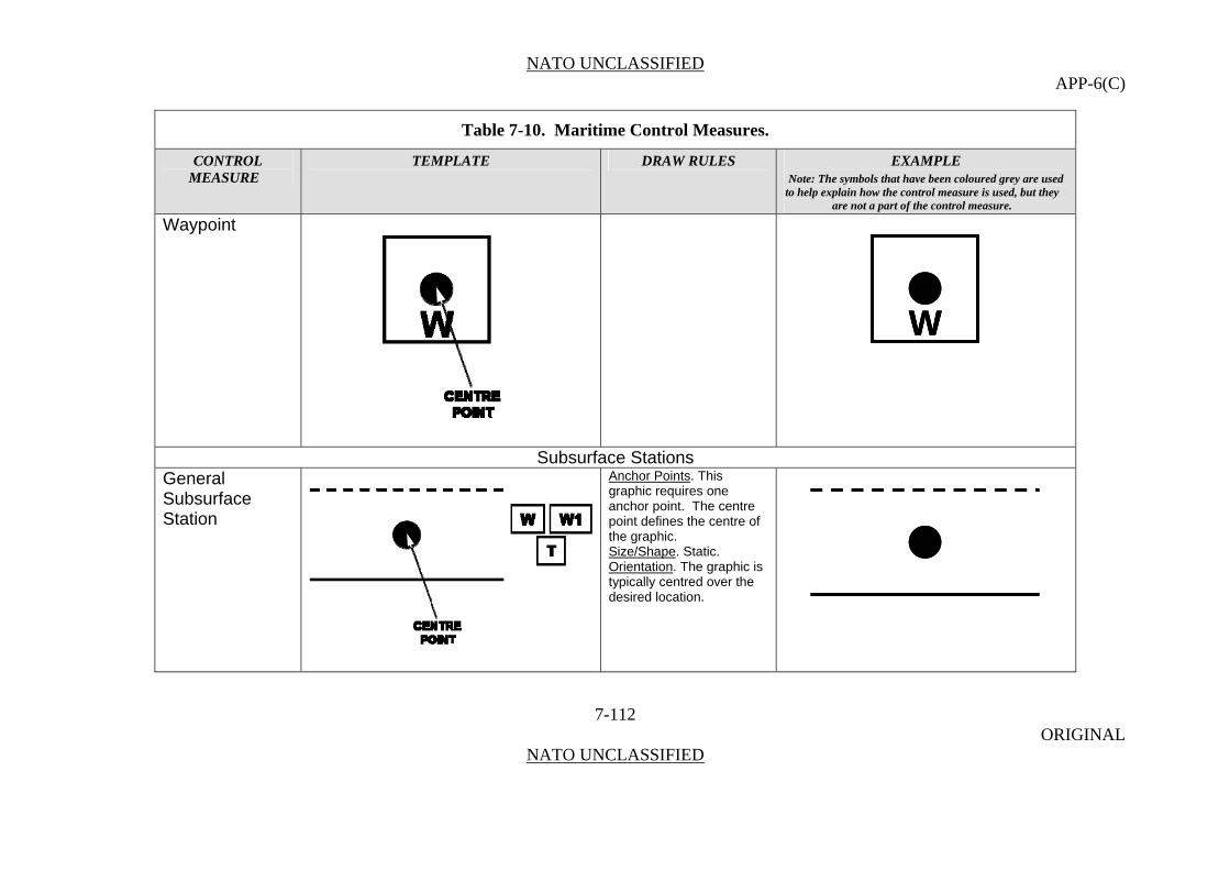
NATO UNCLASSIFIED APP-6(C)
Table 7-10. Maritime Control Measures.
CONTROL TEMPLATE DRAW RULES EXAMPLE MEASURE Note: The symbols that have been coloured grey are used
to help explain how the control measure is used, but they are not a part of the control measure.
Waypoint
WWW
Subsurface Stations General Subsurface Station
Anchor Points. This graphic requires one anchor point. The centre point defines the centre of the graphic. Size/Shape. Static. Orientation. The graphic is typically centred over the desired location.
7-112 ORIGINAL
NATO UNCLASSIFIED

NATO UNCLASSIFIED APP-6(C)
Table 7-10. Maritime Control Measures.
CONTROL TEMPLATE DRAW RULES EXAMPLE MEASURE Note: The symbols that have been coloured grey are used
to help explain how the control measure is used, but they are not a part of the control measure.
Submarine Subsurface Station
7-113 ORIGINAL
NATO UNCLASSIFIED
SSSS
Submarine Antisubmarine Warfare Subsurface Station
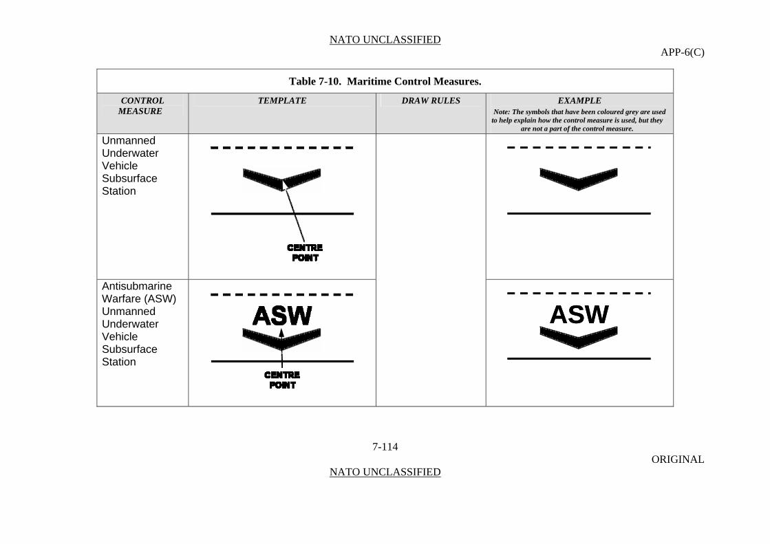
NATO UNCLASSIFIED APP-6(C)
Table 7-10. Maritime Control Measures.
CONTROL TEMPLATE DRAW RULES EXAMPLE MEASURE Note: The symbols that have been coloured grey are used
to help explain how the control measure is used, but they are not a part of the control measure.
Unmanned Underwater Vehicle Subsurface Station
7-114 ORIGINAL
NATO UNCLASSIFIED
Antisubmarine Warfare (ASW) Unmanned Underwater Vehicle Subsurface Station
ASWASW
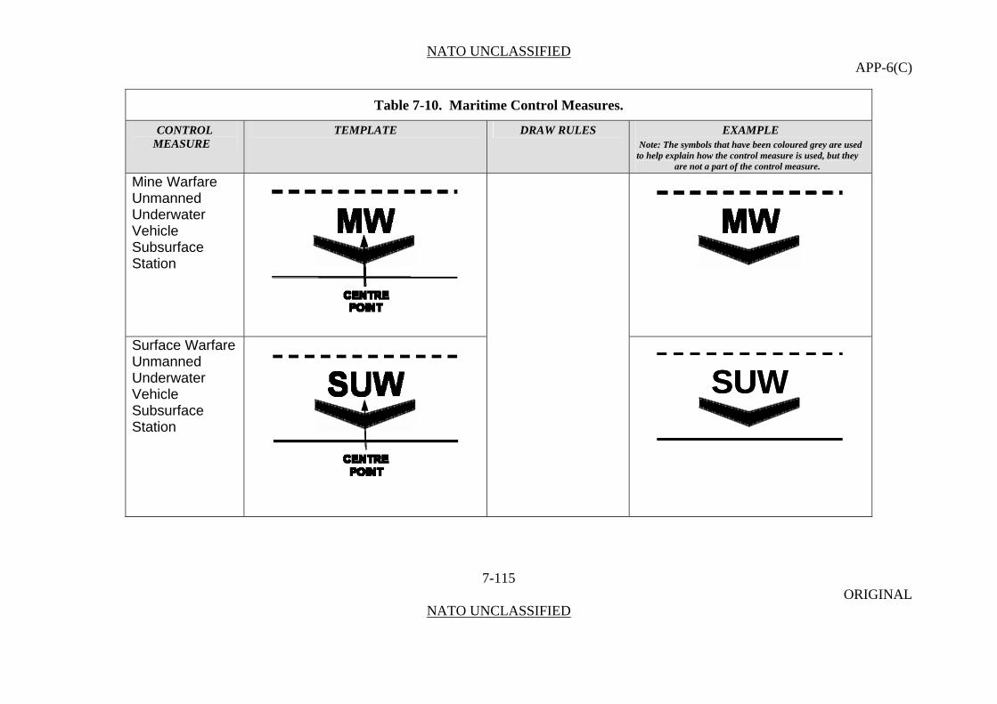
NATO UNCLASSIFIED APP-6(C)
Table 7-10. Maritime Control Measures.
CONTROL TEMPLATE DRAW RULES EXAMPLE MEASURE Note: The symbols that have been coloured grey are used
to help explain how the control measure is used, but they are not a part of the control measure.
Mine Warfare Unmanned Underwater Vehicle Subsurface Station
7-115 ORIGINAL
NATO UNCLASSIFIED
Surface Warfare Unmanned Underwater Vehicle Subsurface Station
SUWSUW
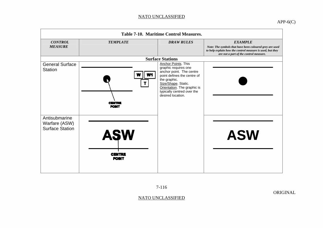
NATO UNCLASSIFIED APP-6(C)
Table 7-10. Maritime Control Measures.
CONTROL TEMPLATE DRAW RULES EXAMPLE MEASURE Note: The symbols that have been coloured grey are used
to help explain how the control measure is used, but they are not a part of the control measure.
Surface Stations General Surface Station
7-116 ORIGINAL
NATO UNCLASSIFIED
Anchor Points. This graphic requires one anchor point. The centre point defines the centre of the graphic. Size/Shape. Static. Orientation. The graphic is typically centred over the desired location.
Antisubmarine Warfare (ASW) Surface Station
ASWASW
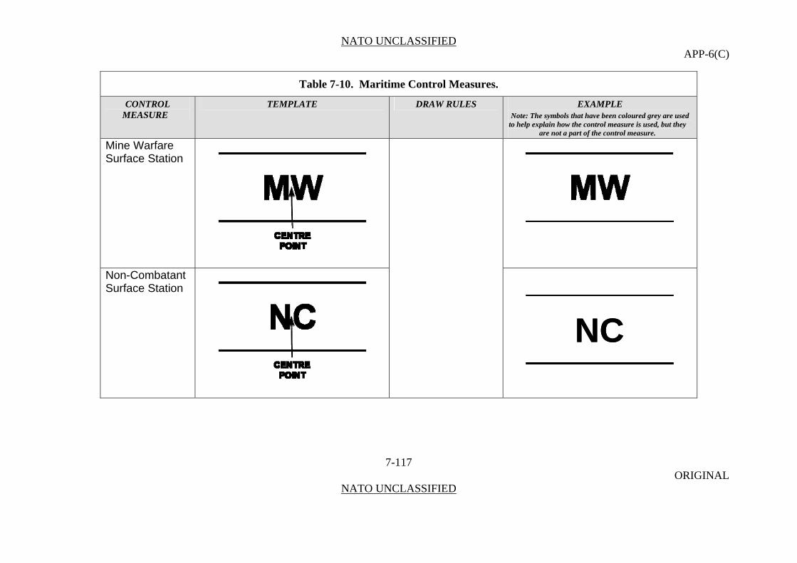
NATO UNCLASSIFIED APP-6(C)
Table 7-10. Maritime Control Measures.
CONTROL TEMPLATE DRAW RULES EXAMPLE MEASURE Note: The symbols that have been coloured grey are used
to help explain how the control measure is used, but they are not a part of the control measure.
Mine Warfare Surface Station
7-117 ORIGINAL
NATO UNCLASSIFIED
Non-Combatant Surface Station
NCNC

NATO UNCLASSIFIED APP-6(C)
Table 7-10. Maritime Control Measures.
CONTROL TEMPLATE DRAW RULES EXAMPLE MEASURE Note: The symbols that have been coloured grey are used
to help explain how the control measure is used, but they are not a part of the control measure.
Picket Surface Station
7-118 ORIGINAL
NATO UNCLASSIFIED
PKPK
Rendezvous Surface Station
RZRZ
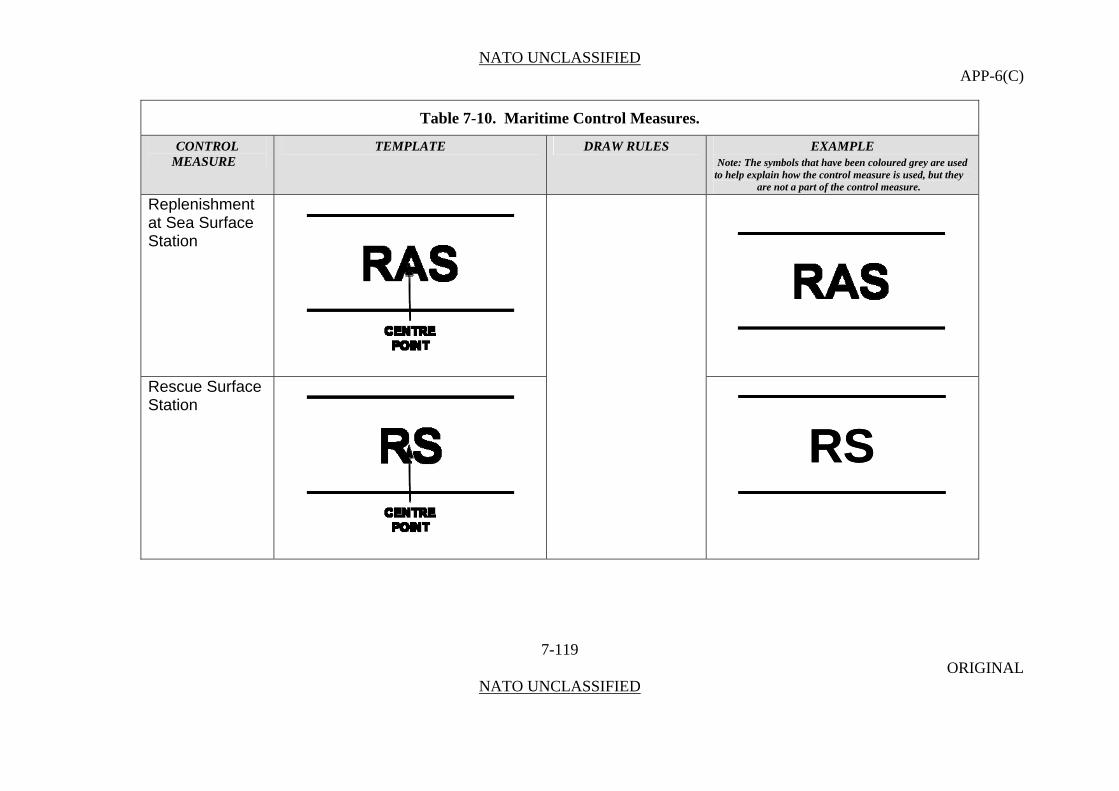
NATO UNCLASSIFIED APP-6(C)
Table 7-10. Maritime Control Measures.
CONTROL TEMPLATE DRAW RULES EXAMPLE MEASURE Note: The symbols that have been coloured grey are used
to help explain how the control measure is used, but they are not a part of the control measure.
Replenishment at Sea Surface Station
7-119 ORIGINAL
NATO UNCLASSIFIED
Rescue Surface Station
RSRS
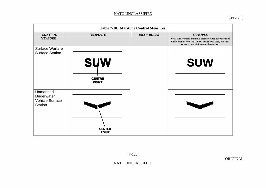
NATO UNCLASSIFIED APP-6(C)
Table 7-10. Maritime Control Measures.
CONTROL TEMPLATE DRAW RULES EXAMPLE MEASURE Note: The symbols that have been coloured grey are used
to help explain how the control measure is used, but they are not a part of the control measure.
Surface Warfare Surface Station
7-120 ORIGINAL
NATO UNCLASSIFIED
SUWSUW
Unmanned Underwater Vehicle Surface Station
CENTER POINT
CENTER POINT
CENTER POINT

NATO UNCLASSIFIED APP-6(C)
Table 7-10. Maritime Control Measures.
CONTROL TEMPLATE DRAW RULES EXAMPLE MEASURE Note: The symbols that have been coloured grey are used
to help explain how the control measure is used, but they are not a part of the control measure.
Antisubmarine Warfare (ASW) Unmanned Underwater Vehicle Surface Station
7-121 ORIGINAL
NATO UNCLASSIFIED
ASWASW
Mine Warfare Unmanned Underwater Vehicle Surface Station

NATO UNCLASSIFIED APP-6(C)
Table 7-10. Maritime Control Measures.
CONTROL TEMPLATE DRAW RULES EXAMPLE MEASURE Note: The symbols that have been coloured grey are used
to help explain how the control measure is used, but they are not a part of the control measure.
Remote Multi-Mission Vehicle Unmanned Underwater Vehicle Surface Station
7-122 ORIGINAL
NATO UNCLASSIFIED
RMVRMV
Surface Warfare Unmanned Underwater Vehicle Surface Station
SUWSUW

NATO UNCLASSIFIED APP-6(C)
Table 7-10. Maritime Control Measures.
CONTROL TEMPLATE DRAW RULES EXAMPLE MEASURE Note: The symbols that have been coloured grey are used
to help explain how the control measure is used, but they are not a part of the control measure.
Routes General Route
7-123 ORIGINAL
NATO UNCLASSIFIED
Anchor Points. This graphic requires one anchor point. The centre point defines the centre of the graphic’s straight line. Size/Shape. Static. Orientation. The graphic is typically centred over the desired location.
Diversion
DDD
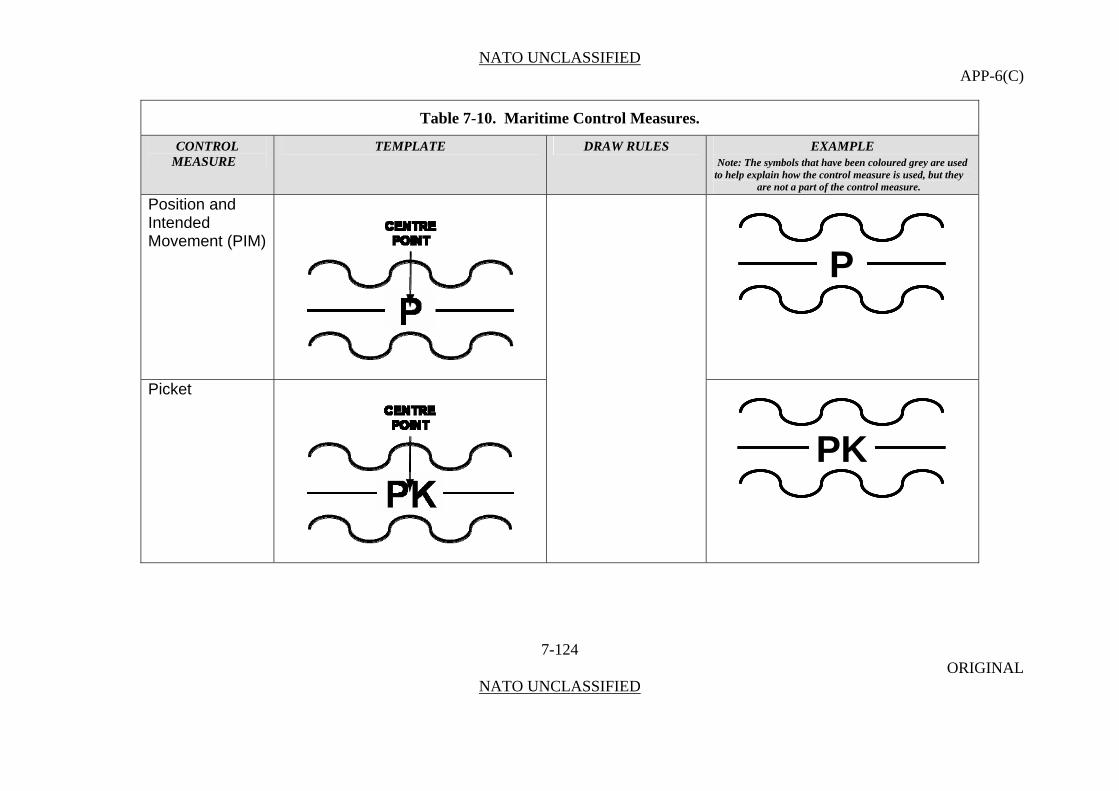
NATO UNCLASSIFIED APP-6(C)
Table 7-10. Maritime Control Measures.
CONTROL TEMPLATE DRAW RULES EXAMPLE MEASURE Note: The symbols that have been coloured grey are used
to help explain how the control measure is used, but they are not a part of the control measure.
Position and Intended Movement (PIM)
7-124 ORIGINAL
NATO UNCLASSIFIED
PPP
Picket
PKPKPK
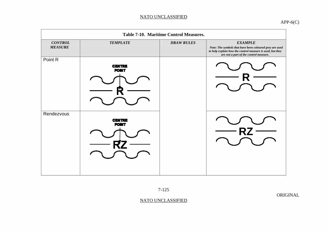
NATO UNCLASSIFIED APP-6(C)
Table 7-10. Maritime Control Measures.
CONTROL TEMPLATE DRAW RULES EXAMPLE MEASURE Note: The symbols that have been coloured grey are used
to help explain how the control measure is used, but they are not a part of the control measure.
Point R
7-125 ORIGINAL
NATO UNCLASSIFIED
RR
Rendezvous
RZRZRZ

NATO UNCLASSIFIED APP-6(C)
Table 7-10. Maritime Control Measures.
CONTROL TEMPLATE DRAW RULES EXAMPLE MEASURE Note: The symbols that have been coloured grey are used
to help explain how the control measure is used, but they are not a part of the control measure.
Waypoint
WWW
Emergency
7-126 ORIGINAL
NATO UNCLASSIFIED
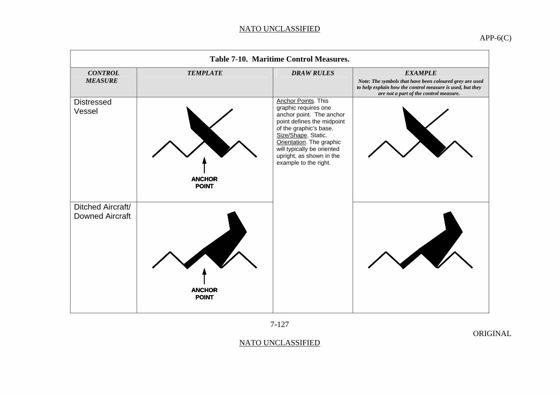
NATO UNCLASSIFIED APP-6(C)
Table 7-10. Maritime Control Measures.
CONTROL TEMPLATE DRAW RULES EXAMPLE MEASURE Note: The symbols that have been coloured grey are used
to help explain how the control measure is used, but they are not a part of the control measure.
Distressed Vessel
7-127 ORIGINAL
NATO UNCLASSIFIED
ANCHORPOINT
ANCHORPOINT
ANCHORPOINT
Anchor Points. This graphic requires one anchor point. The anchor point defines the midpoint of the graphic’s base. Size/Shape. Static. Orientation. The graphic will typically be oriented upright, as shown in the example to the right.
Ditched Aircraft/ Downed Aircraft
ANCHORPOINT
ANCHORPOINT
ANCHORPOINT

NATO UNCLASSIFIED APP-6(C)
Table 7-10. Maritime Control Measures.
CONTROL TEMPLATE DRAW RULES EXAMPLE MEASURE Note: The symbols that have been coloured grey are used
to help explain how the control measure is used, but they are not a part of the control measure.
Person In Water/Bailout
ANCHORPOINT
ANCHORPOINT
ANCHORPOINT
7-128 ORIGINAL
NATO UNCLASSIFIED
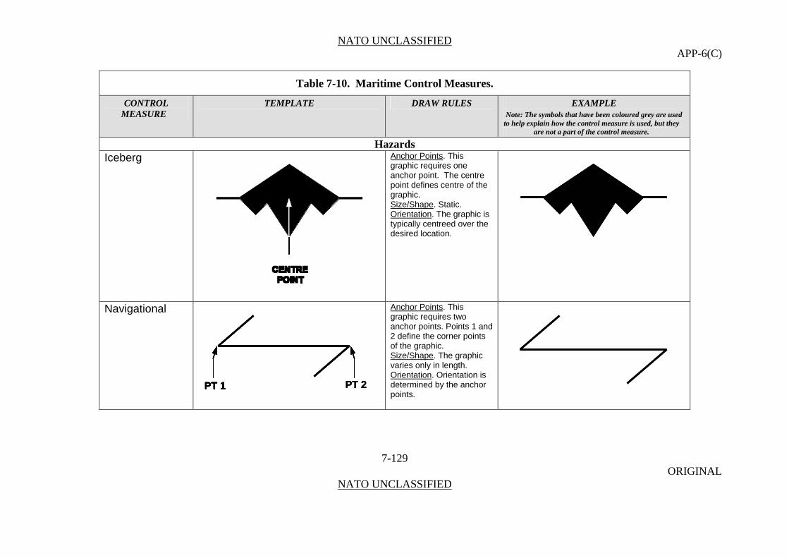
NATO UNCLASSIFIED APP-6(C)
Table 7-10. Maritime Control Measures.
CONTROL TEMPLATE DRAW RULES EXAMPLE MEASURE Note: The symbols that have been coloured grey are used
to help explain how the control measure is used, but they are not a part of the control measure.
Hazards Iceberg Anchor Points. This
graphic requires one anchor point. The centre point defines centre of the graphic. Size/Shape. Static. Orientation. The graphic is typically centreed over the desired location.
Navigational Anchor Points. This graphic requires two anchor points. Points 1 and 2 define the corner points of the graphic.
PT 2PT 1 PT 2PT 2PT 1PT 1PT 1
Size/Shape. The graphic varies only in length. Orientation
7-129 ORIGINAL
NATO UNCLASSIFIED
. Orientation is determined by the anchor points.
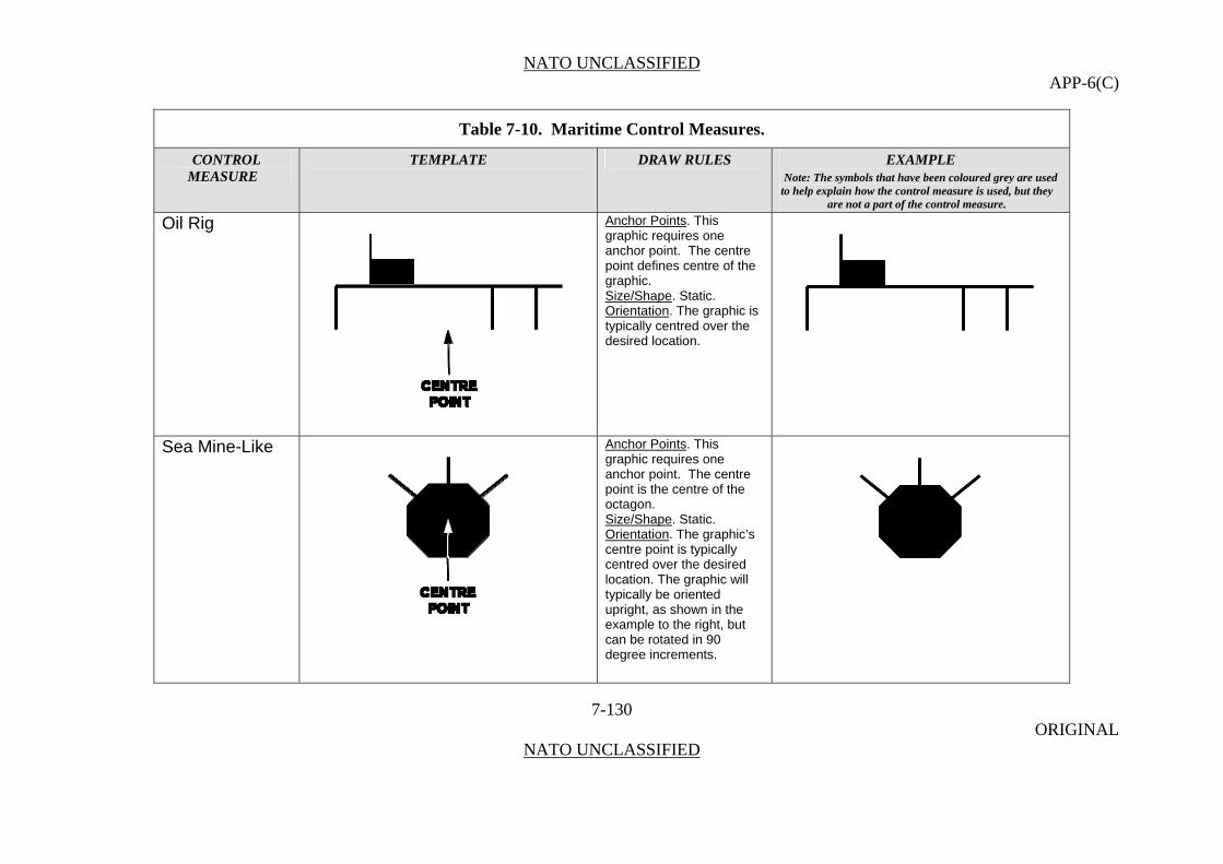
NATO UNCLASSIFIED APP-6(C)
Table 7-10. Maritime Control Measures.
CONTROL TEMPLATE DRAW RULES EXAMPLE MEASURE Note: The symbols that have been coloured grey are used
to help explain how the control measure is used, but they are not a part of the control measure.
Oil Rig Anchor Points. This graphic requires one anchor point. The centre point defines centre of the graphic. Size/Shape. Static. Orientation
7-130 ORIGINAL
NATO UNCLASSIFIED
. The graphic is typically centred over the desired location.
Sea Mine-Like Anchor Points. This graphic requires one anchor point. The centre point is the centre of the octagon. Size/Shape. Static. Orientation. The graphic’s centre point is typically centred over the desired location. The graphic will typically be oriented upright, as shown in the example to the right, but can be rotated in 90 degree increments.

NATO UNCLASSIFIED APP-6(C)
Table 7-10. Maritime Control Measures.
CONTROL TEMPLATE DRAW RULES EXAMPLE MEASURE Note: The symbols that have been coloured grey are used
to help explain how the control measure is used, but they are not a part of the control measure.
Sea Subsurface Returns Bottom Return/ Non-Mine, Mine-Like Bottom Object (NOMBO)
7-131 ORIGINAL
NATO UNCLASSIFIED
ANCHORPOINT
ANCHORPOINT
ANCHORPOINT
Anchor Points. This graphic requires one anchor point. The anchor point defines the midpoint of the graphic’s base. Size/Shape. Static. Orientation. The graphic will typically be oriented upright, as shown in the example to the right, but can be rotated in 90 degree increments.
Bottom Return/ Non-Mine, Mine-Like Bottom Object (NOMBO)/ Installation/ Manmade
ANCHORPOINT
ANCHORPOINT
ANCHORPOINT
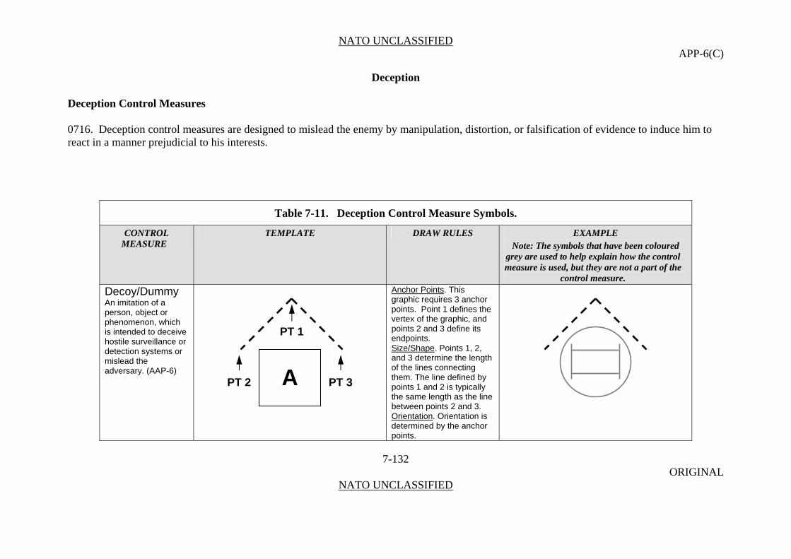
NATO UNCLASSIFIED APP-6(C)
Deception
Deception Control Measures
0716. Deception control measures are designed to mislead the enemy by manipulation, distortion, or falsification of evidence to induce him to react in a manner prejudicial to his interests.
Table 7-11. Deception Control Measure Symbols.
CONTROL TEMPLATE DRAW RULES EXAMPLE MEASURE Note: The symbols that have been coloured
grey are used to help explain how the control measure is used, but they are not a part of the
control measure.
Decoy/Dummy Anchor Points. This graphic requires 3 anchor points. Point 1 defines the vertex of the graphic, and points 2 and 3 define its endpoints.
7-132 ORIGINAL
NATO UNCLASSIFIED
An imitation of a person, object or phenomenon, which is intended to deceive hostile surveillance or detection systems or mislead the adversary. (AAP-6)
Size/Shape. Points 1, 2, and 3 determine the length of the lines connecting them. The line defined by points 1 and 2 is typically the same length as the line between points 2 and 3. Orientation. Orientation is determined by the anchor points.
PT 1
PT 2 PT 3 A

NATO UNCLASSIFIED APP-6(C)
Decoy/Dummy Note: Anchor points are determined by the relationship between the control measure symbol being modified and the decoy/dummy or feint control measure symbol modifying it. See the specific control measure being modified for anchor points.
7-133 ORIGINAL
NATO UNCLASSIFIED
and Feint In military deception, an offensive action involving contact with the adversary conducted for the purpose of deceiving the adversary as to the location and/or time of the actual main offensive action.
Axis of Advance for a Feint
See Axis of Advance under Manoeuvre Control Measures (Page 7-47)
Direction of Attack for a Feint
See Direction of Attack under Manoeuvre Control Measures (Page 7-51)
Decoy Mined Area
See Decoy Mined Area under Obstacles (Page 7-168)
Dummy Minefield
See Decoy Mined Minefield under Obstacles (Page 7-169)
PT 2
PT 1
PT 3
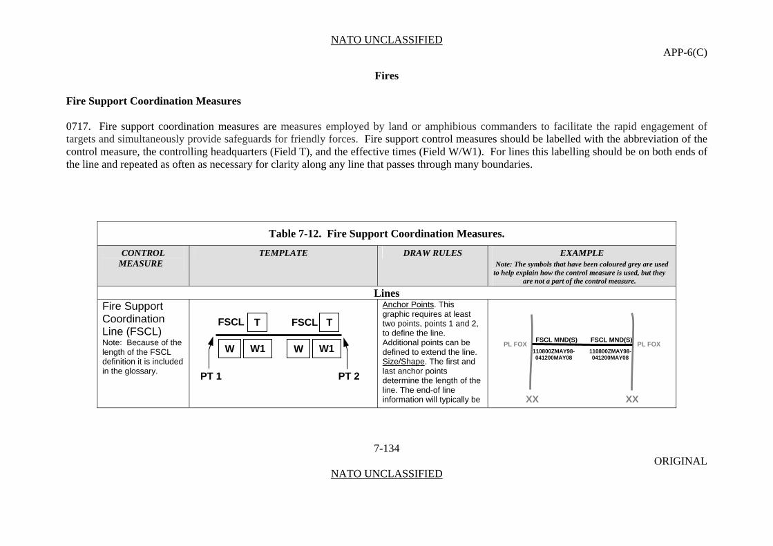
NATO UNCLASSIFIED APP-6(C)
Fires
Fire Support Coordination Measures
0717. Fire support coordination measures are measures employed by land or amphibious commanders to facilitate the rapid engagement of targets and simultaneously provide safeguards for friendly forces. Fire support control measures should be labelled with the abbreviation of the control measure, the controlling headquarters (Field T), and the effective times (Field W/W1). For lines this labelling should be on both ends of the line and repeated as often as necessary for clarity along any line that passes through many boundaries.
Table 7-12. Fire Support Coordination Measures.
CONTROL TEMPLATE DRAW RULES EXAMPLE MEASURE Note: The symbols that have been coloured grey are used
to help explain how the control measure is used, but they are not a part of the control measure.
Lines Fire Support Coordination Line (FSCL)
Anchor Points. This graphic requires at least two points, points 1 and 2, to define the line. Additional points can be defined to extend the line.
7-134 ORIGINAL
NATO UNCLASSIFIED
Note: Because of the length of the FSCL definition it is included in the glossary.
Size/Shape. The first and last anchor points determine the length of the line. The end-of line information will typically be
FSCL TFSCL T
W W1 W W1
PT 2 PT 1
PL FOX
XX XX
PL FOXFSCL MND(S) FSCL MND(S)
110800ZMAY98- 110800ZMAY98- 041200MAY08 041200MAY08
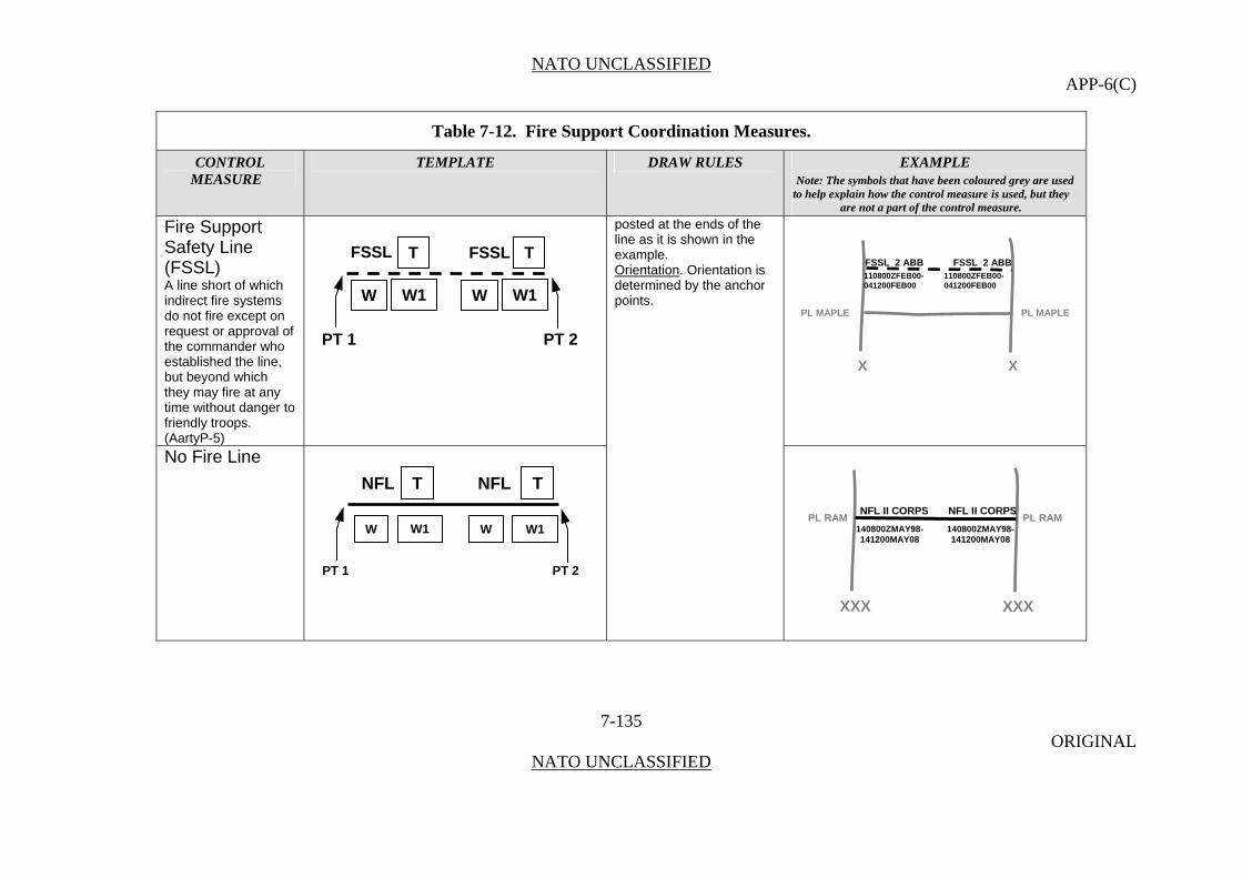
NATO UNCLASSIFIED APP-6(C)
Table 7-12. Fire Support Coordination Measures.
CONTROL TEMPLATE DRAW RULES EXAMPLE MEASURE Note: The symbols that have been coloured grey are used
to help explain how the control measure is used, but they are not a part of the control measure.
Fire Support Safety Line (FSSL)
7-135 ORIGINAL
NATO UNCLASSIFIED
A line short of which indirect fire systems do not fire except on request or approval of the commander who established the line, but beyond which they may fire at any time without danger to friendly troops. (AartyP-5)
posted at the ends of the line as it is shown in the example.
No Fire Line
Orientation. Orientation is determined by the anchor points.
FSSL TFSSL T
W W1 W W1
PT 2 PT 1
X X
PL MAPLE PL MAPLE
FSSL 2 ABB FSSL 2 ABB 110800ZFEB00- 110800ZFEB00- 041200FEB00 041200FEB00
NFL TNFL T
W W1 W W1
PT 2 PT 1
PL RAM
XXX
PL RAMNFL II CORPS NFL II CORPS
140800ZMAY98- 140800ZMAY98- 141200MAY08 141200MAY08
XXX
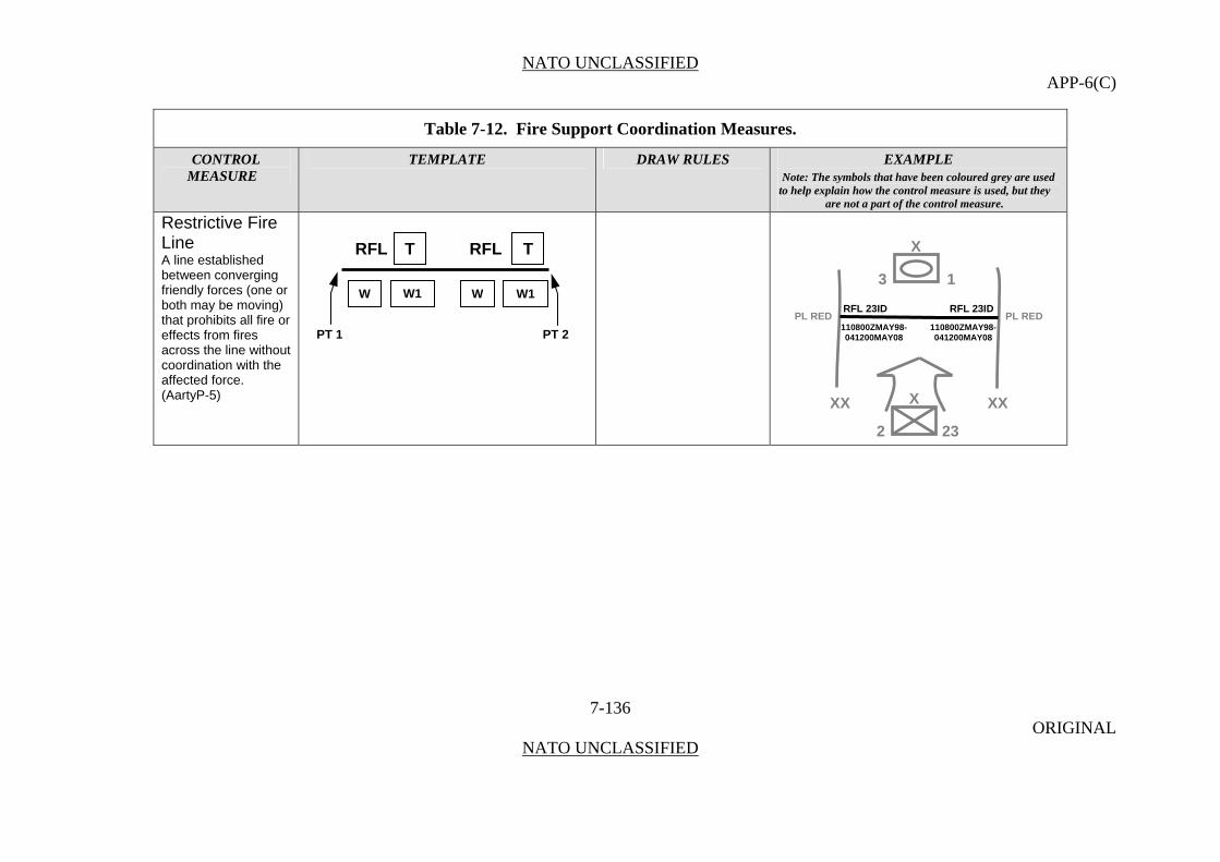
NATO UNCLASSIFIED APP-6(C)
Table 7-12. Fire Support Coordination Measures.
CONTROL TEMPLATE DRAW RULES EXAMPLE MEASURE Note: The symbols that have been coloured grey are used
to help explain how the control measure is used, but they are not a part of the control measure.
Restrictive Fire Line
7-136 ORIGINAL
NATO UNCLASSIFIED
A line established between converging friendly forces (one or both may be moving) that prohibits all fire or effects from fires across the line without coordination with the affected force. (AartyP-5)
XRFL T RFL T
W W1 W W1
PT 2 PT 1 PL RED
3 1
RFL 23ID RFL 23IDPL RED
XX XX X
110800ZMAY98- 110800ZMAY98- 041200MAY08 041200MAY08
2 23

NATO UNCLASSIFIED APP-6(C)
Table 7-12. Fire Support Coordination Measures.
CONTROL TEMPLATE DRAW RULES EXAMPLE MEASURE Note: The symbols that have been coloured grey are used
to help explain how the control measure is used, but they are not a part of the control measure.
Areas Airspace Coordination Area (ACA)
Anchor Points. This graphic requires at least three anchor points to define the boundary of the area. Add as many points as necessary to accurately reflect the area’s size and shape.
7-137 ORIGINAL
NATO UNCLASSIFIED
A restricted area or route of travel specified for use by friendly aircraft and established for the purpose of preventing friendly aircraft from being fired on by friendly forces. (AartyP-5)
Size/Shape. Determined by the anchor points. The information fields should be movable and scalable as a block within the area. Field W1 is optional. Orientation. Not applicable.
ACAACA
T MND(N) MIN ALT 500 MAX ALT 3000 MIN ALTGRID FD1173, FD825,
MAX ALT FD8211, FD1111 240000ZDEC07- 291100ZDEC07 Y
W W1

NATO UNCLASSIFIED APP-6(C)
Table 7-12. Fire Support Coordination Measures.
CONTROL TEMPLATE DRAW RULES EXAMPLE MEASURE Note: The symbols that have been coloured grey are used
to help explain how the control measure is used, but they are not a part of the control measure.
Free Fire Area (FFA)
7-138 ORIGINAL
NATO UNCLASSIFIED
A specific designated area into which any weapon system may fire without additional co-ordination with the establishing headquarters.
No Fire Area (NFA) An area into which no fires or the effects of fires are allowed.
FFAFFA
T 2AD (DEU) 031230ZMAY07-072330ZMAY07
W W1
NFANFA
T 52ID (GBR) 051230ZMAY07-072330ZMAY07
W W1

NATO UNCLASSIFIED APP-6(C)
Table 7-12. Fire Support Coordination Measures.
CONTROL TEMPLATE DRAW RULES EXAMPLE MEASURE Note: The symbols that have been coloured grey are used
to help explain how the control measure is used, but they are not a part of the control measure.
Restricted Fire Area (RFA)
7-139 ORIGINAL
NATO UNCLASSIFIED
An area in which specific restrictions are imposed and in which fires that exceed those restrictions are not delivered without co-ordination with the establishing headquarters. (AartyP-5)
RFA
T
W W1
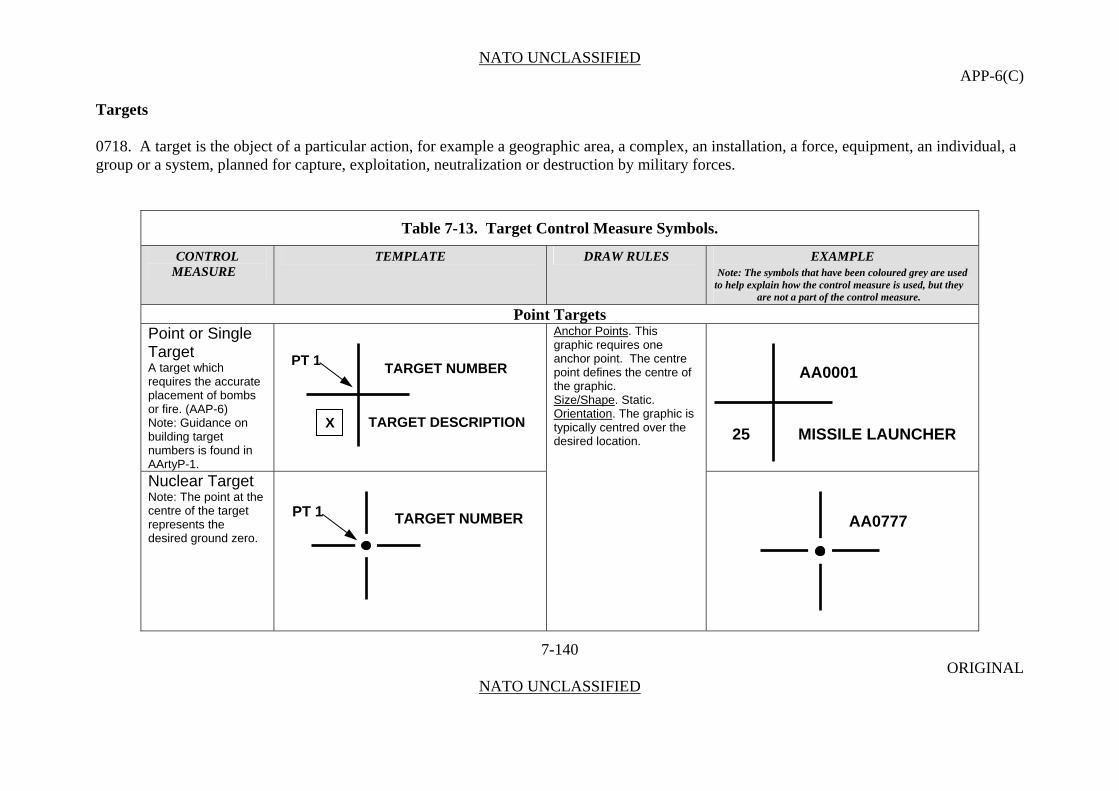
NATO UNCLASSIFIED APP-6(C)
Targets
0718. A target is the object of a particular action, for example a geographic area, a complex, an installation, a force, equipment, an individual, a group or a system, planned for capture, exploitation, neutralization or destruction by military forces.
Table 7-13. Target Control Measure Symbols.
CONTROL TEMPLATE DRAW RULES EXAMPLE MEASURE Note: The symbols that have been coloured grey are used
to help explain how the control measure is used, but they are not a part of the control measure.
Point Targets Point or Single Target
7-140 ORIGINAL
NATO UNCLASSIFIED
A target which requires the accurate placement of bombs or fire. (AAP-6) Note: Guidance on building target numbers is found in AArtyP-1.
Anchor Points. This graphic requires one anchor point. The centre point defines the centre of the graphic.
Nuclear Target Note: The point at the centre of the target represents the desired ground zero.
Size/Shape. Static. Orientation. The graphic is typically centred over the desired location.
TARGET DESCRIPTION
TARGET NUMBER
X
PT 1 AA0001
25 MISSILE LAUNCHER
TARGET NUMBER PT 1 AA0777
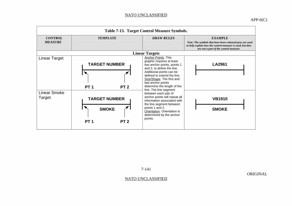
NATO UNCLASSIFIED APP-6(C)
Table 7-13. Target Control Measure Symbols.
CONTROL TEMPLATE DRAW RULES EXAMPLE MEASURE Note: The symbols that have been coloured grey are used
to help explain how the control measure is used, but they are not a part of the control measure.
Linear Targets Linear Target
7-141 ORIGINAL
NATO UNCLASSIFIED
Anchor Points. This graphic requires at least two anchor points, points 1 and 2, to define the line.
Linear Smoke Target
Additional points can be defined to extend the line. Size/Shape. The first and last anchor points determine the length of the line. The line segment between each pair of anchor points will repeat all information associated with the line segment between points 1 and 2. Orientation. Orientation is determined by the anchor points.
TARGET NUMBER LA2961
PT 1 PT 2
TARGET NUMBER VB1910
SMOKE SMOKE
PT 1 PT 2

NATO UNCLASSIFIED APP-6(C)
Table 7-13. Target Control Measure Symbols.
CONTROL TEMPLATE DRAW RULES EXAMPLE MEASURE Note: The symbols that have been coloured grey are used
to help explain how the control measure is used, but they are not a part of the control measure.
Final Protective Fire (FPF)
7-142 ORIGINAL
NATO UNCLASSIFIED
An immediately available prearranged barrier of fire designed to impede enemy movement across defensive lines or areas. (AAP-6)
Area Targets Circular Target
Anchor Points. This graphic requires one (1) anchor point. Point 1 defines the centre point of the graphic. Size/Shape. Size: The radius, defined in meters, determines the size of the Circular Target. Shape: Circle. The information fields should be movable and scaleable within the circle. Orientation. Not applicable.
FPF
T
V
TARGET NUMBER QC1968
FPF 12 IN BN MORTAR
PT 1 PT 2
TARGET NUMBER
DA0786 RADIUS
PT 1

NATO UNCLASSIFIED APP-6(C)
Table 7-13. Target Control Measure Symbols.
CONTROL TEMPLATE DRAW RULES EXAMPLE MEASURE Note: The symbols that have been coloured grey are used
to help explain how the control measure is used, but they are not a part of the control measure.
Rectangular Target
Anchor Points. This graphic requires one (1) anchor point to define the centre of the area.
7-143 ORIGINAL
NATO UNCLASSIFIED
Size/Shape. Size Is determined by the anchor point, the target length (in meters), and target width (in meters). A rectangular target is wider and longer than 200 meters. The information fields should be moveable and scaleable within the area. Shape: Rectangle. Orientation. As determined by the Target Attitude (in mils).
LENGTH
BE0065 WIDTH
TARGET NUMBER ATTITUDE
PT 1
Irregular Target Anchor Points. This graphic requires at least three anchor points to define the boundary of the area. Add as many points as necessary to accurately reflect the area’s size and shape. Size/Shape. Determined by the anchor points. The information field should be moveable within the area. Orientation. Not applicable.
TARGET NUMBER
PC9008
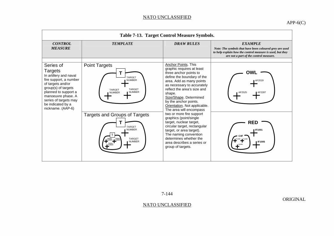
NATO UNCLASSIFIED APP-6(C)
Table 7-13. Target Control Measure Symbols.
CONTROL TEMPLATE DRAW RULES EXAMPLE MEASURE Note: The symbols that have been coloured grey are used
to help explain how the control measure is used, but they are not a part of the control measure.
7-144 ORIGINAL
NATO UNCLASSIFIED
Point Targets
Series of Targets
Anchor Points. This graphic requires at least three anchor points to define the boundary of the area. Add as many points as necessary to accurately reflect the area’s size and shape.
In artillery and naval fire support, a number of targets and/or group(s) of targets planned to support a manoeuvre phase. A series of targets may be indicated by a nickname. (AAP-6)
Targets and Groups of Targets
Size/Shape. Determined by the anchor points. Orientation. Not applicable. The area will encompass two or more fire support graphics (point/single target, nuclear target, circular target, rectangular target, or area target). The naming convention determines whether the area describes a series or group of targets.
TARGET NUMBER
OWL TTARGET NUMBER AF2019
TARGET AF2525 AF2287NUMBER
RED
C4F
IF1001
IF1005 KL0001
KL0002 KL0003 TARGET NUMBER
TTARGET NUMBER
T
TARGETNUMBER
TARGETNUMBER
TARGETNUMBER

NATO UNCLASSIFIED APP-6(C)
Table 7-13. Target Control Measure Symbols.
CONTROL TEMPLATE DRAW RULES EXAMPLE MEASURE Note: The symbols that have been coloured grey are used
to help explain how the control measure is used, but they are not a part of the control measure.
7-145 ORIGINAL
NATO UNCLASSIFIED
Point Targets
Group of Targets
Two or more targets on which fire is desired simultaneously. A group of targets is designated by a letter/number combination or a nickname. (AAP-6) Linear Targets
TARGET NUMBER
C7F TTARGET NUMBER KF2019
TARGET KF2525 KF2287NUMBER
TM9W
TARGETNUMBER
TARGETNUMBER
TARGETNUMBER
UA0127 UA0227
UA0177

NATO UNCLASSIFIED APP-6(C)
Table 7-13. Target Control Measure Symbols.
CONTROL TEMPLATE DRAW RULES EXAMPLE MEASURE Note: The symbols that have been coloured grey are used
to help explain how the control measure is used, but they are not a part of the control measure.
Area Targets
7-146 ORIGINAL
NATO UNCLASSIFIED
T V2P
TARGET TARGETFC6705 FC6706 NUMBER NUMBER
TARGETFC6704 NUMBER
Smoke
Anchor Points. This graphic requires at least three anchor points to define the boundary of the area. Add as many points as necessary to accurately reflect the area’s size and shape.
Smoke Planned or On Order
Size/Shape. Determined by the anchor points. The information field should be moveable within the area. Orientation. Not applicable.
SMOKE SMOKE
SMOKE SMOKE 010700ZJAN08-
W W1010745ZJAN08
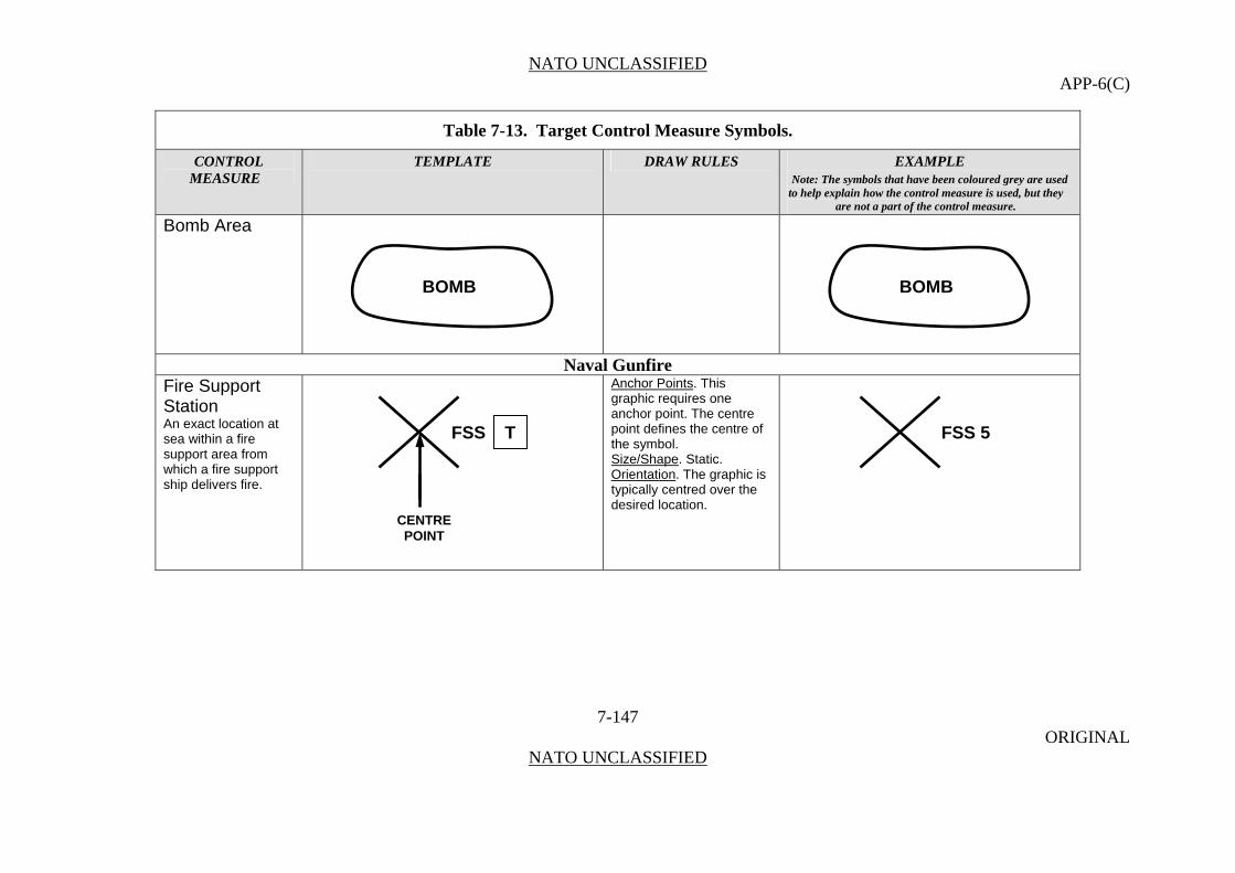
NATO UNCLASSIFIED APP-6(C)
Table 7-13. Target Control Measure Symbols.
CONTROL TEMPLATE DRAW RULES EXAMPLE MEASURE Note: The symbols that have been coloured grey are used
to help explain how the control measure is used, but they are not a part of the control measure.
Bomb Area
7-147 ORIGINAL
NATO UNCLASSIFIED
Naval Gunfire Fire Support Station An exact location at sea within a fire support area from which a fire support ship delivers fire.
Anchor Points. This graphic requires one anchor point. The centre point defines the centre of the symbol. Size/Shape. Static. Orientation. The graphic is typically centred over the desired location.
BOMB BOMB
FSS T FSS 5
CENTRE POINT
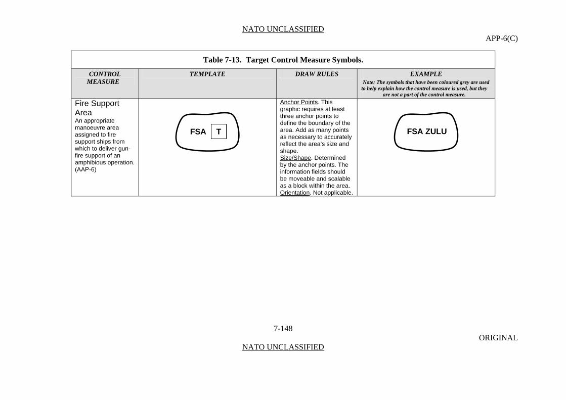
NATO UNCLASSIFIED APP-6(C)
Table 7-13. Target Control Measure Symbols.
CONTROL TEMPLATE DRAW RULES EXAMPLE MEASURE Note: The symbols that have been coloured grey are used
to help explain how the control measure is used, but they are not a part of the control measure.
Fire Support Area
Anchor Points. This graphic requires at least three anchor points to define the boundary of the area. Add as many points as necessary to accurately reflect the area’s size and shape.
7-148 ORIGINAL
NATO UNCLASSIFIED
An appropriate manoeuvre area assigned to fire support ships from which to deliver gun-fire support of an amphibious operation. (AAP-6)
Size/Shape. Determined by the anchor points. The information fields should be moveable and scalable as a block within the area. Orientation. Not applicable.
FSA ZULU FSA T

NATO UNCLASSIFIED APP-6(C)
Table 7-13. Target Control Measure Symbols.
CONTROL TEMPLATE DRAW RULES EXAMPLE MEASURE Note: The symbols that have been coloured grey are used
to help explain how the control measure is used, but they are not a part of the control measure.
Field Artillery Firing Point Anchor Points. This
graphic requires one anchor point. The point defines the tip of the inverted cone.
7-149 ORIGINAL
NATO UNCLASSIFIED
Size/Shape. Static. Orientation. The graphic will typically be oriented upright, as shown in the example to the right.
FP
1
2FP
1
2
H
W TFP
W1T
ANCHORPOINT

NATO UNCLASSIFIED APP-6(C)
Table 7-13. Target Control Measure Symbols.
CONTROL TEMPLATE DRAW RULES EXAMPLE MEASURE Note: The symbols that have been coloured grey are used
to help explain how the control measure is used, but they are not a part of the control measure.
Hide Point
HP
H
T
TW
W1
ANCHORPOINT
HP
H
T
TW
W1
W
W1
ANCHORPOINTANCHORPOINT
HP
2/A
3HP
2/A
3
7-150 ORIGINAL
NATO UNCLASSIFIED
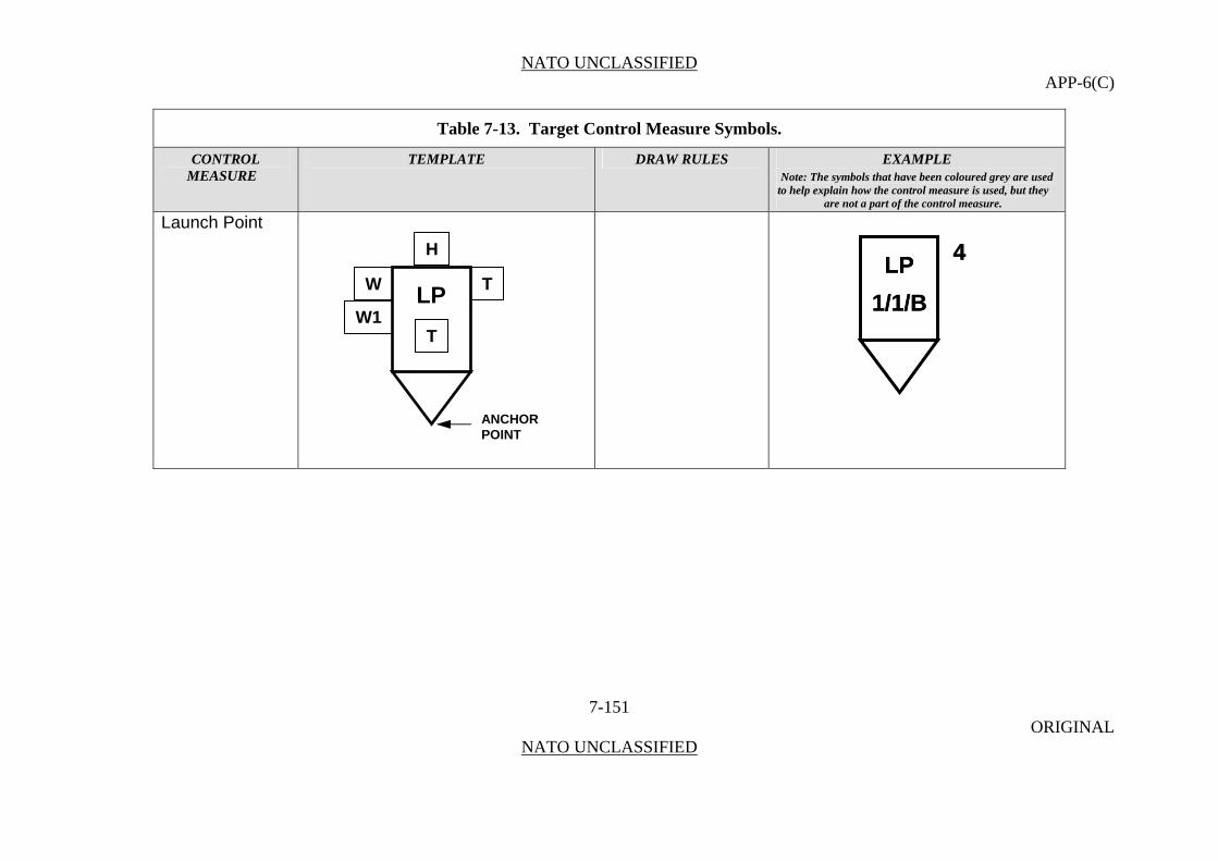
NATO UNCLASSIFIED APP-6(C)
Table 7-13. Target Control Measure Symbols.
CONTROL TEMPLATE DRAW RULES EXAMPLE MEASURE Note: The symbols that have been coloured grey are used
to help explain how the control measure is used, but they are not a part of the control measure.
Launch Point
7-151 ORIGINAL
NATO UNCLASSIFIED
LP
1/1/B
4LP
1/1/B
4
H
W TLP
W1T
ANCHORPOINT
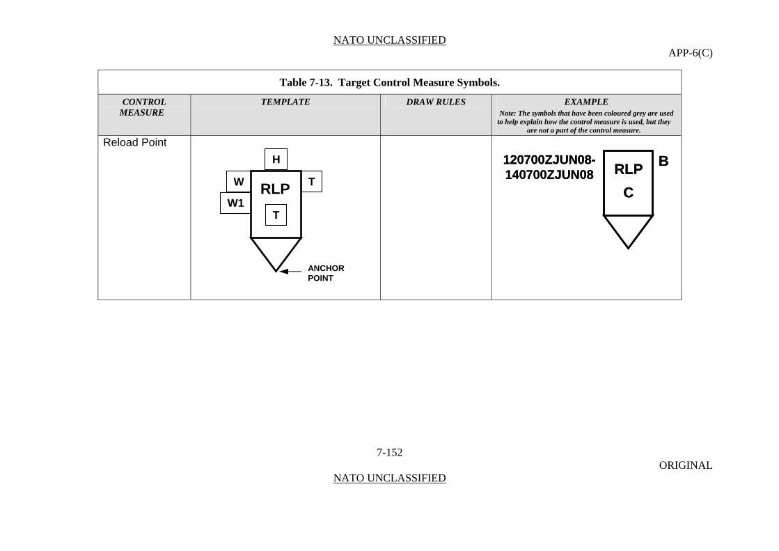
NATO UNCLASSIFIED APP-6(C)
Table 7-13. Target Control Measure Symbols.
CONTROL TEMPLATE DRAW RULES EXAMPLE MEASURE Note: The symbols that have been coloured grey are used
to help explain how the control measure is used, but they are not a part of the control measure.
Reload Point
7-152 ORIGINAL
NATO UNCLASSIFIED
RLP
C
B120700ZJUN08-140700ZJUN08 RLP
C
B120700ZJUN08-140700ZJUN08
H
W TRLP
W1T
ANCHORPOINT
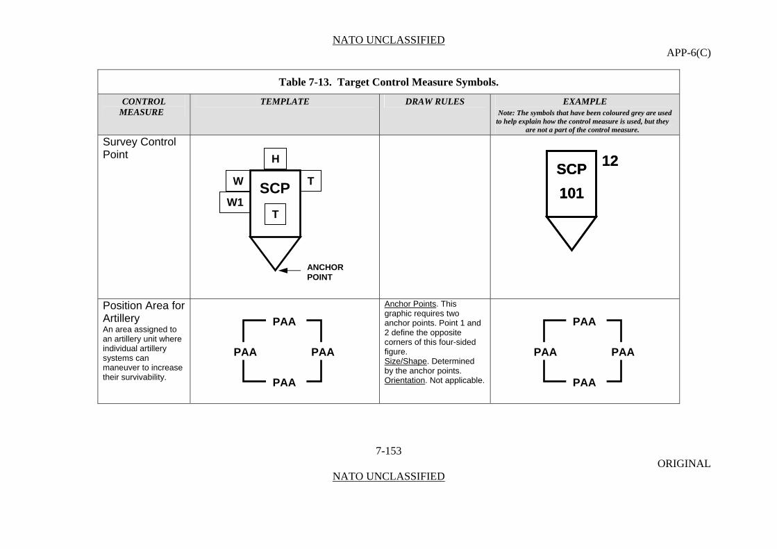
NATO UNCLASSIFIED APP-6(C)
Table 7-13. Target Control Measure Symbols.
CONTROL TEMPLATE DRAW RULES EXAMPLE MEASURE Note: The symbols that have been coloured grey are used
to help explain how the control measure is used, but they are not a part of the control measure.
Survey Control Point
7-153 ORIGINAL
NATO UNCLASSIFIED
SCP
101
12SCP
101
12
Position Area for Artillery An area assigned to an artillery unit where individual artillery systems can maneuver to increase their survivability.
Anchor Points. This graphic requires two anchor points. Point 1 and 2 define the opposite corners of this four-sided figure. Size/Shape. Determined by the anchor points. Orientation. Not applicable.
H
W TSCP
W1T
ANCHORPOINT
PAA
PAA PAA
PAA PAA PAA PAA
PAA
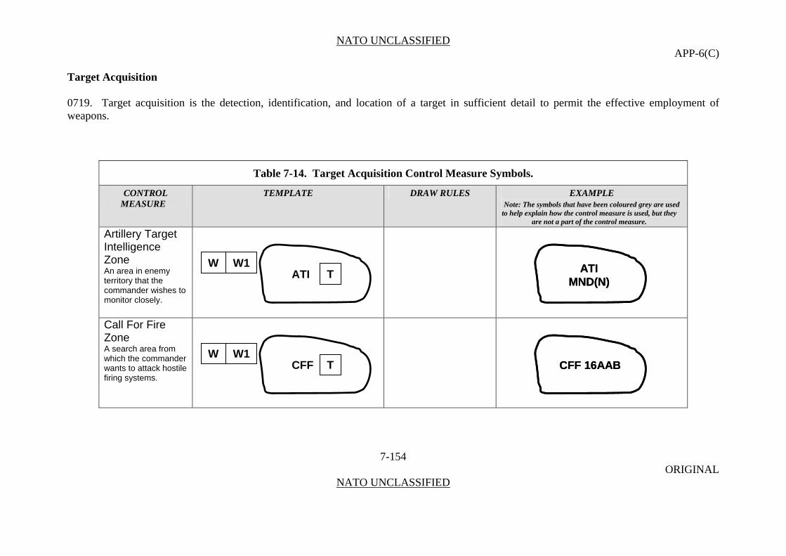
NATO UNCLASSIFIED APP-6(C)
Target Acquisition 0719. Target acquisition is the detection, identification, and location of a target in sufficient detail to permit the effective employment of weapons.
Table 7-14. Target Acquisition Control Measure Symbols.
CONTROL TEMPLATE DRAW RULES EXAMPLE MEASURE Note: The symbols that have been coloured grey are used
to help explain how the control measure is used, but they are not a part of the control measure.
Artillery Target Intelligence Zone
ATIMND(N)
ATIMND(N)
7-154 ORIGINAL
NATO UNCLASSIFIED
An area in enemy territory that the commander wishes to monitor closely.
Call For Fire Zone A search area from which the commander wants to attack hostile firing systems.
CFF 16AABCFF 16AAB
W W1TATI
W W1TCFF
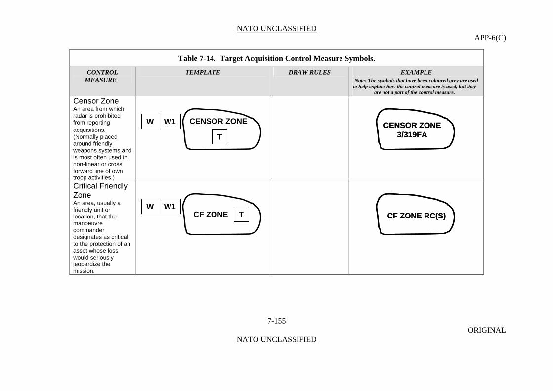
NATO UNCLASSIFIED APP-6(C)
Table 7-14. Target Acquisition Control Measure Symbols.
CONTROL TEMPLATE DRAW RULES EXAMPLE MEASURE Note: The symbols that have been coloured grey are used
to help explain how the control measure is used, but they are not a part of the control measure.
Censor Zone
CENSOR ZONE3/319FA
CENSOR ZONE3/319FA
7-155 ORIGINAL
NATO UNCLASSIFIED
An area from which radar is prohibited from reporting acquisitions. (Normally placed around friendly weapons systems and is most often used in non-linear or cross forward line of own troop activities.)
Critical Friendly Zone An area, usually a friendly unit or location, that the manoeuvre commander designates as critical to the protection of an asset whose loss would seriously jeopardize the mission.
CF ZONE RC(S)CF ZONE RC(S)
TCF ZONEW W1
T
CENSOR ZONEW W1

NATO UNCLASSIFIED APP-6(C)
Table 7-14. Target Acquisition Control Measure Symbols.
CONTROL TEMPLATE DRAW RULES EXAMPLE MEASURE Note: The symbols that have been coloured grey are used
to help explain how the control measure is used, but they are not a part of the control measure.
Dead Space Area
DA 6/37FADA 6/37FA
7-156 ORIGINAL
NATO UNCLASSIFIED
An area where hostile weapons cannot be detected.
Sensor Zone
SENSOR ZONERC(N)
SENSOR ZONERC(N)
Target Build-up Area
TBA RC(W)TBA RC(W)
W W1TDA
TBA TW W1
W W1
T
SENSOR ZONE

NATO UNCLASSIFIED APP-6(C)
Table 7-14. Target Acquisition Control Measure Symbols.
CONTROL TEMPLATE DRAW RULES EXAMPLE MEASURE Note: The symbols that have been coloured grey are used
to help explain how the control measure is used, but they are not a part of the control measure.
Target Value Area
TVAR RC(E)TVAR RC(E)
7-157 ORIGINAL
NATO UNCLASSIFIED
W W1
Zone of Responsibility
ZOR RC(C)ZOR RC(C)
ZOR TW W1
TVAR T
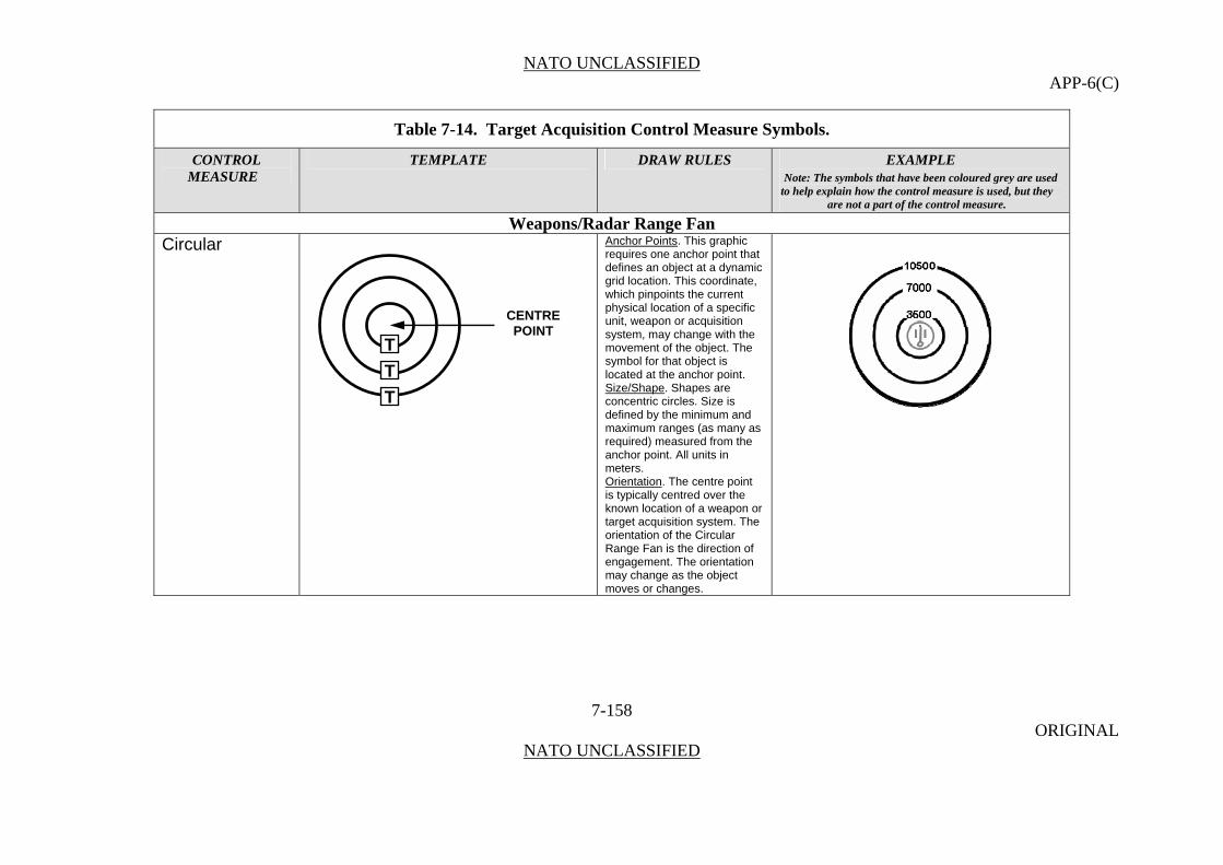
NATO UNCLASSIFIED APP-6(C)
Table 7-14. Target Acquisition Control Measure Symbols.
CONTROL TEMPLATE DRAW RULES EXAMPLE MEASURE Note: The symbols that have been coloured grey are used
to help explain how the control measure is used, but they are not a part of the control measure.
Weapons/Radar Range Fan Circular Anchor Points. This graphic
requires one anchor point that defines an object at a dynamic grid location. This coordinate, which pinpoints the current physical location of a specific unit, weapon or acquisition system, may change with the movement of the object. The symbol for that object is located at the anchor point.
7-158 ORIGINAL
NATO UNCLASSIFIED
Size/Shape. Shapes are concentric circles. Size is defined by the minimum and maximum ranges (as many as required) measured from the anchor point. All units in meters. Orientation. The centre point is typically centred over the known location of a weapon or target acquisition system. The orientation of the Circular Range Fan is the direction of engagement. The orientation may change as the object moves or changes.
CENTRE POINT
T
T
T

NATO UNCLASSIFIED APP-6(C)
Table 7-14. Target Acquisition Control Measure Symbols.
CONTROL TEMPLATE DRAW RULES EXAMPLE MEASURE Note: The symbols that have been coloured grey are used
to help explain how the control measure is used, but they are not a part of the control measure.
Sector Anchor Points. This graphic requires one anchor point that defines an object at a dynamic grid location. This coordinate, which pinpoints the current physical location of a specific unit, weapon or acquisition system, may change with the movement of the object. The symbol for that object is located at the anchor point.
8400
5600
2800
3006100
8400
5600
2800
3006100
8400
5600
2800
3006100
Size/Shape. Determined from the anchor point with a single azimuth that denotes Sector Centre. The maximum left and right limits of the sector are measured from the sector centreline. Multiple ranges and/or maximum left
and right limits of the sector, as well as height, may be entered, as required, to define the sector. All ranges in meters. Orientation. The centre point is typically centred over the known location of a weapon or target acquisition system. The orientation may change as the object moves or changes.
7-159 ORIGINAL
NATO UNCLASSIFIED
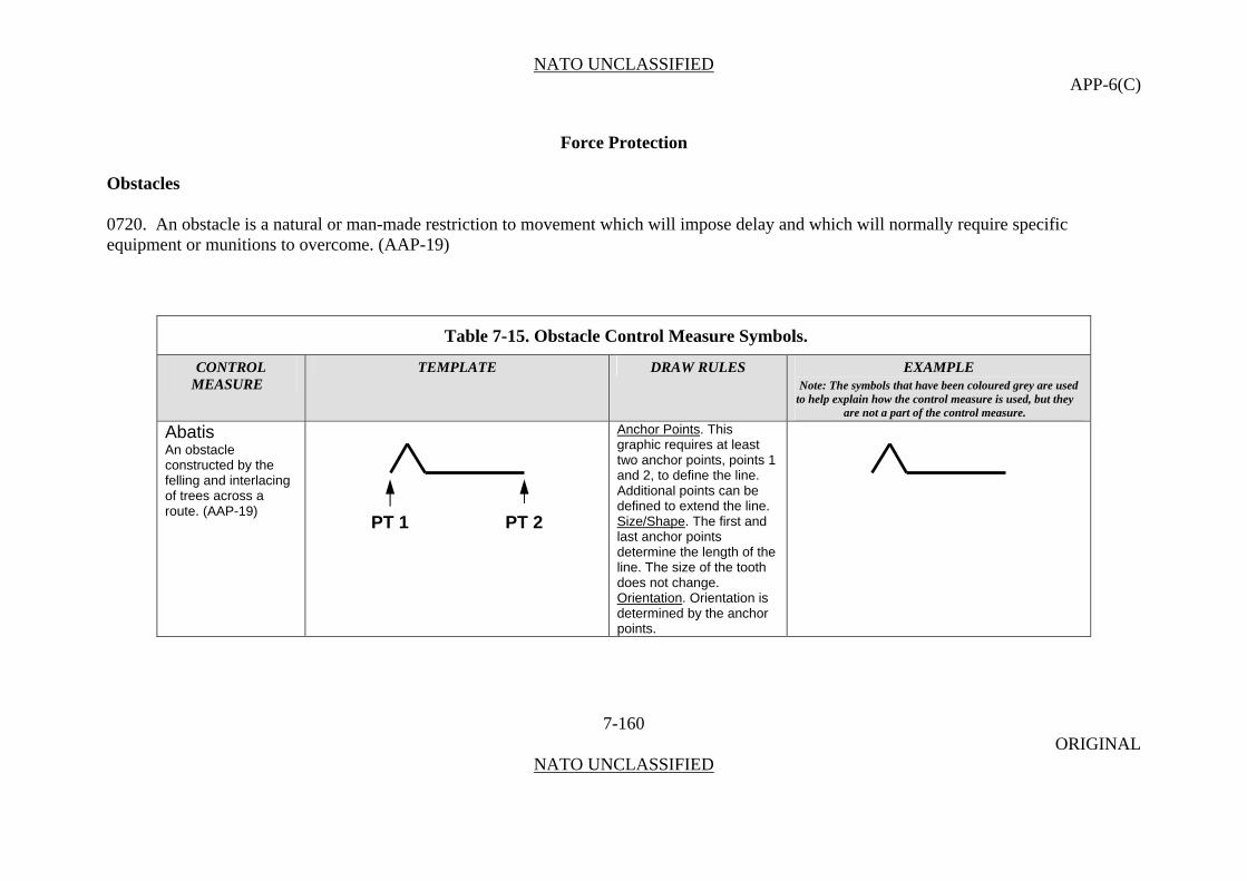
NATO UNCLASSIFIED APP-6(C)
Force Protection Obstacles
0720. An obstacle is a natural or man-made restriction to movement which will impose delay and which will normally require specific equipment or munitions to overcome. (AAP-19)
Table 7-15. Obstacle Control Measure Symbols.
CONTROL TEMPLATE DRAW RULES EXAMPLE MEASURE Note: The symbols that have been coloured grey are used
to help explain how the control measure is used, but they are not a part of the control measure.
Abatis Anchor Points. This graphic requires at least two anchor points, points 1 and 2, to define the line.
7-160 ORIGINAL
NATO UNCLASSIFIED
An obstacle constructed by the felling and interlacing of trees across a route. (AAP-19)
Additional points can be defined to extend the line.
Size/Shape. The first and last anchor points determine the length of the line. The size of the tooth does not change. Orientation. Orientation is determined by the anchor points.
PT 1 PT 2

NATO UNCLASSIFIED APP-6(C)
Table 7-15. Obstacle Control Measure Symbols.
CONTROL TEMPLATE DRAW RULES EXAMPLE MEASURE Note: The symbols that have been coloured grey are used
to help explain how the control measure is used, but they are not a part of the control measure.
Obstacle Line Anchor Points. This graphic requires at least two anchor points, points 1 and 2, to define the line.
7-161 ORIGINAL
NATO UNCLASSIFIED
A conceptual control measure used at battalion or brigade level to show placement intent without specifying a particular type of linear obstacle.
Additional points can be defined to extend the line. Size/Shape. The first and last anchor points determine the length of the line. Orientation. Orientation is determined by the anchor points.
Obstacle Belt An area designated at brigade level in which barrier operations are focused. (AAP-19)
Anchor Points. This graphic requires at least three anchor points to define the boundary of the area. Add as many points as necessary to accurately reflect the area’s size and shape. Size/Shape. Determined by the anchor points. The information fields should
T3-4CAV
PT 2 PT 1
1-3 INT

NATO UNCLASSIFIED APP-6(C)
Table 7-15. Obstacle Control Measure Symbols.
CONTROL TEMPLATE DRAW RULES EXAMPLE MEASURE Note: The symbols that have been coloured grey are used
to help explain how the control measure is used, but they are not a part of the control measure.
Obstacle Zone
7-162 ORIGINAL
NATO UNCLASSIFIED
An area designated at corps or division level in which barrier operations are focused. It may be subdivided, below division, into a number of obstacle belts. (AAP-19)
5-7 RAR 5-7 RAR
be moveable within the area. Orientation. Not applicable.
Obstacle Free Zone
T

NATO UNCLASSIFIED APP-6(C)
Table 7-15. Obstacle Control Measure Symbols.
CONTROL TEMPLATE DRAW RULES EXAMPLE MEASURE Note: The symbols that have been coloured grey are used
to help explain how the control measure is used, but they are not a part of the control measure.
Obstacle Restricted Zone
7-163 ORIGINAL
NATO UNCLASSIFIED
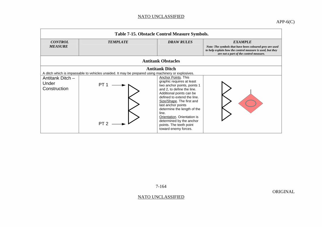
NATO UNCLASSIFIED APP-6(C)
Table 7-15. Obstacle Control Measure Symbols.
CONTROL TEMPLATE DRAW RULES EXAMPLE MEASURE Note: The symbols that have been coloured grey are used
to help explain how the control measure is used, but they are not a part of the control measure.
Antitank Obstacles
Antitank Ditch A ditch which is impassable to vehicles unaided. It may be prepared using machinery or explosives. Antitank Ditch – Under Construction
Anchor Points. This graphic requires at least two anchor points, points 1 and 2, to define the line.
7-164 ORIGINAL
NATO UNCLASSIFIED
Additional points can be defined to extend the line. Size/Shape. The first and last anchor points determine the length of the line. Orientation. Orientation is determined by the anchor points. The teeth point toward enemy forces.
PT 1
PT 2
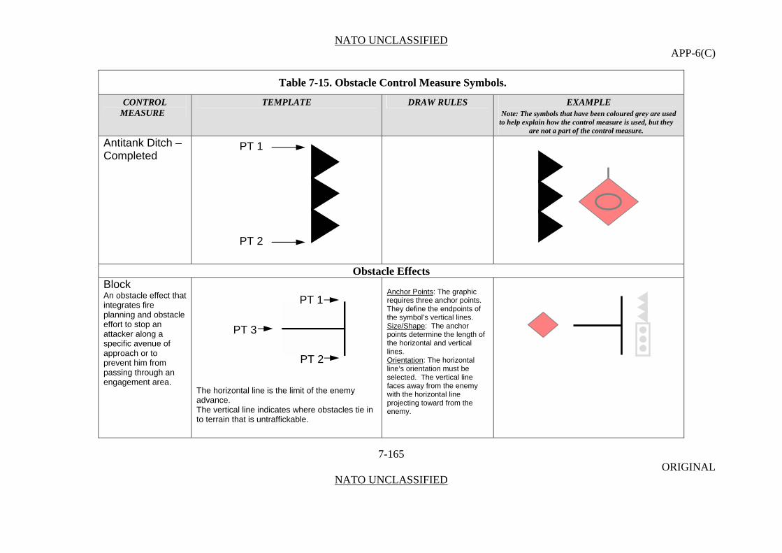
NATO UNCLASSIFIED APP-6(C)
Table 7-15. Obstacle Control Measure Symbols.
CONTROL TEMPLATE DRAW RULES EXAMPLE MEASURE Note: The symbols that have been coloured grey are used
to help explain how the control measure is used, but they are not a part of the control measure.
Antitank Ditch – Completed
7-165 ORIGINAL
NATO UNCLASSIFIED
Obstacle Effects Block An obstacle effect that integrates fire planning and obstacle effort to stop an attacker along a specific avenue of approach or to prevent him from passing through an engagement area.
The horizontal line is the limit of the enemy advance. The vertical line indicates where obstacles tie in to terrain that is untraffickable.
Anchor Points: The graphic requires three anchor points. They define the endpoints of the symbol’s vertical lines. Size/Shape: The anchor points determine the length of the horizontal and vertical lines. Orientation: The horizontal line’s orientation must be selected. The vertical line faces away from the enemy with the horizontal line projecting toward from the enemy.
PT 1
PT 2
PT 1
PT 2
PT 3

NATO UNCLASSIFIED APP-6(C)
Table 7-15. Obstacle Control Measure Symbols.
CONTROL TEMPLATE DRAW RULES EXAMPLE MEASURE Note: The symbols that have been coloured grey are used
to help explain how the control measure is used, but they are not a part of the control measure.
7-166 ORIGINAL
NATO UNCLASSIFIED
Disrupt Anchor Points: This graphic requires three anchor points. Points 1 and 2 define the end points of the graphic’s vertical line. Point 3 defines the tip of the longest arrow.
An obstacle effect that focuses fire planning and obstacle effort to cause the enemy to break up his formation and tempo, interrupt his timetable, commit breaching assets prematurely, and attack in a piecemeal effort.
PT 3 PT 1
Size/Shape
Short arrow indicates where enemy is disrupted by obstacles. Longer arrows indicates where movement is allowed and enemy is attacked by fires.
: Points 1 and 2 determine the height of the graphic and point 3 determines its length. The spacing between the graphic’s arrows will stay proportional to the graphic’s vertical line. The length of the short arrows will remain in proportion to the length of the longest arrow.
PT 2
Orientation: The arrows point away from enemy forces.
Fix Anchor Points: This graphic requires 2 anchor points. Point 1 defines the tip of the arrowhead, and point 2 defines the rear of the graphic.2
An obstacle effect that focuses fire planning and obstacle effort to slow an attacker’s movement within a specified area,
Size/Shape: Points 1 and 2 determine the length of the
PT 2 PT 1
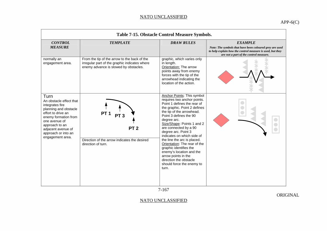
NATO UNCLASSIFIED APP-6(C)
Table 7-15. Obstacle Control Measure Symbols.
CONTROL TEMPLATE DRAW RULES EXAMPLE MEASURE Note: The symbols that have been coloured grey are used
to help explain how the control measure is used, but they are not a part of the control measure.
7-167 ORIGINAL
NATO UNCLASSIFIED
normally an engagement area.
From the tip of the arrow to the back of the irregular part of the graphic indicates where enemy advance is slowed by obstacles.
graphic, which varies only in length.
Orientation: The arrow points away from enemy forces with the tip of the arrowhead indicating the location of the action.
Turn Anchor Points: This symbol requires two anchor points. Point 1 defines the rear of the graphic. Point 2 defines the tip of the arrowhead. Point 3 defines the 90
An obstacle effect that integrates fire planning and obstacle effort to drive an enemy formation from one avenue of approach to an adjacent avenue of approach or into an engagement area.
Direction of the arrow indicates the desired direction of turn.
degree arc. Size/Shape: Points 1 and 2 are connected by a 90 degree arc. Point 3 indicates on which side of the line the arc is placed. Orientation: The rear of the graphic identifies the enemy’s location and the arrow points in the direction the obstacle should force the enemy to turn.
PT 2
PT 1 PT 3
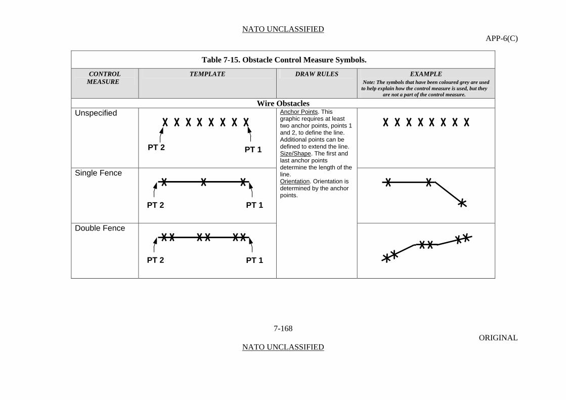
NATO UNCLASSIFIED APP-6(C)
Table 7-15. Obstacle Control Measure Symbols.
CONTROL TEMPLATE DRAW RULES EXAMPLE MEASURE Note: The symbols that have been coloured grey are used
to help explain how the control measure is used, but they are not a part of the control measure.
Wire Obstacles Unspecified
7-168 ORIGINAL
NATO UNCLASSIFIED
Anchor Points. This graphic requires at least two anchor points, points 1 and 2, to define the line.
Single Fence
Double Fence
Additional points can be defined to extend the line. Size/Shape. The first and last anchor points determine the length of the line. Orientation. Orientation is determined by the anchor points.
PT 2 PT 1
PT 2 PT 1
PT 2 PT 1
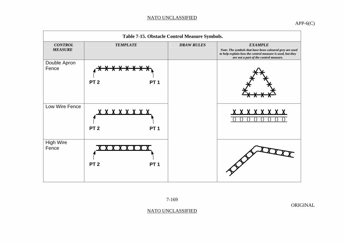
NATO UNCLASSIFIED APP-6(C)
Table 7-15. Obstacle Control Measure Symbols.
CONTROL TEMPLATE DRAW RULES EXAMPLE MEASURE Note: The symbols that have been coloured grey are used
to help explain how the control measure is used, but they are not a part of the control measure.
Double Apron Fence
7-169 ORIGINAL
NATO UNCLASSIFIED
Low Wire Fence
High Wire Fence
PT 2 PT 1
PT 2 PT 1
PT 2 PT 1
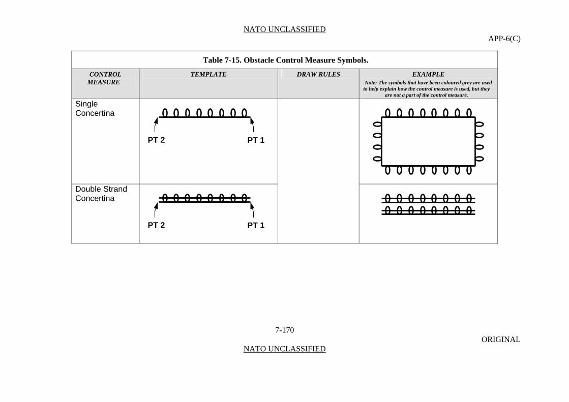
NATO UNCLASSIFIED APP-6(C)
Table 7-15. Obstacle Control Measure Symbols.
CONTROL TEMPLATE DRAW RULES EXAMPLE MEASURE Note: The symbols that have been coloured grey are used
to help explain how the control measure is used, but they are not a part of the control measure.
Single Concertina
7-170 ORIGINAL
NATO UNCLASSIFIED
Double Strand Concertina
PT 2 PT 1
PT 2 PT 1

NATO UNCLASSIFIED APP-6(C)
Table 7-15. Obstacle Control Measure Symbols.
CONTROL TEMPLATE DRAW RULES EXAMPLE MEASURE Note: The symbols that have been coloured grey are used
to help explain how the control measure is used, but they are not a part of the control measure.
Triple Strand Concertina
7-171 ORIGINAL
NATO UNCLASSIFIED
Obstacle Bypass Obstacle Bypass Easy
Anchor Points. This graphic requires three anchor points. Points 1 and 2 define the tips of the arrowheads and point 3 defines the rear of the graphic. Size/Shape. Points 1 and 2 determine the graphic’s height and point 3 determines its length. The vertical line at the rear of the graphic will be the
PT 1
PT 2
PT 3
PT 2 PT 1

NATO UNCLASSIFIED APP-6(C)
Table 7-15. Obstacle Control Measure Symbols.
CONTROL TEMPLATE DRAW RULES EXAMPLE MEASURE Note: The symbols that have been coloured grey are used
to help explain how the control measure is used, but they are not a part of the control measure.
Obstacle Bypass Difficult
same length as the opening.
7-172 ORIGINAL
NATO UNCLASSIFIED
Orientation. The opening typically faces enemy forces.
PT 1PT 3
PT 2
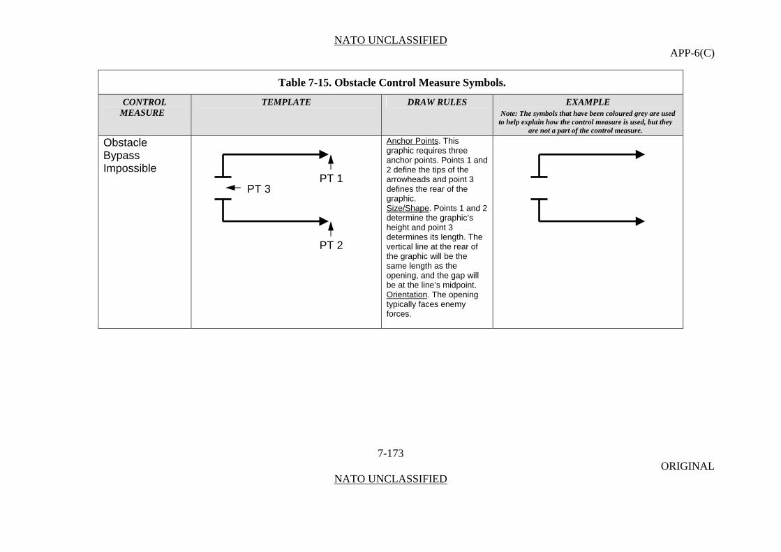
NATO UNCLASSIFIED APP-6(C)
Table 7-15. Obstacle Control Measure Symbols.
CONTROL TEMPLATE DRAW RULES EXAMPLE MEASURE Note: The symbols that have been coloured grey are used
to help explain how the control measure is used, but they are not a part of the control measure.
Obstacle Bypass Impossible
Anchor Points. This graphic requires three anchor points. Points 1 and 2 define the tips of the arrowheads and point 3 defines the rear of the graphic.
7-173 ORIGINAL
NATO UNCLASSIFIED
Size/Shape. Points 1 and 2 determine the graphic’s height and point 3 determines its length. The vertical line at the rear of the graphic will be the same length as the opening, and the gap will be at the line’s midpoint. Orientation. The opening typically faces enemy forces.
PT 1PT 3
PT 2

NATO UNCLASSIFIED APP-6(C)
Table 7-15. Obstacle Control Measure Symbols.
CONTROL TEMPLATE DRAW RULES EXAMPLE MEASURE Note: The symbols that have been coloured grey are used
to help explain how the control measure is used, but they are not a part of the control measure.
Land Mines In land mine warfare, an explosive ammunition designed to be placed under, on or near the ground or other surface area and to be actuated by the presence, proximity or contact of a person, land vehicle, aircraft or boat, including landing craft. (AAP-6) Antipersonnel Mine
7-174 ORIGINAL
NATO UNCLASSIFIED
In land mine warfare, a mine designed to be exploded by the presence, proximity or contact of a person and that will incapacitate, wound or kill one or more persons. (AAP-19)
Anchor Points. This graphic requires one anchor point. The centre point defines the centre of the circle.
Antipersonnel Mine with Directional Effects
Size/Shape. Static. Orientation. The graphic is typically centred over the desired location.
CENTRE POINT
CENTRE POINT
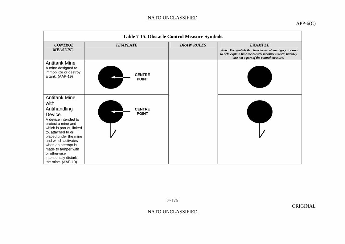
NATO UNCLASSIFIED APP-6(C)
Table 7-15. Obstacle Control Measure Symbols.
CONTROL TEMPLATE DRAW RULES EXAMPLE MEASURE Note: The symbols that have been coloured grey are used
to help explain how the control measure is used, but they are not a part of the control measure.
Antitank Mine
7-175 ORIGINAL
NATO UNCLASSIFIED
A mine designed to immobilize or destroy a tank. (AAP-19)
Antitank Mine with Antihandling Device A device intended to protect a mine and which is part of, linked to, attached to or placed under the mine and which activates when an attempt is made to tamper with or otherwise intentionally disturb the mine. (AAP-19)
CENTRE POINT
CENTRE POINT

NATO UNCLASSIFIED APP-6(C)
Table 7-15. Obstacle Control Measure Symbols.
CONTROL TEMPLATE DRAW RULES EXAMPLE MEASURE Note: The symbols that have been coloured grey are used
to help explain how the control measure is used, but they are not a part of the control measure.
Wide Area Antitank Mine
7-176 ORIGINAL
NATO UNCLASSIFIED
An antitank mine that detects and acquires targets then launches a subammunition that attacks the top of the targets.
CENTRE POINT
Unspecified Mine
Mine Cluster
Anchor Points. This graphic requires at least two anchor points. Points 1 and 2 define the corners of the graphic. Size/Shape. Points 1 and 2 determine the length of the straight line. The radius of the semicircle is ½ the length of the straight line. Orientation. Not applicable.
CENTRE POINT
PT 2 PT 1
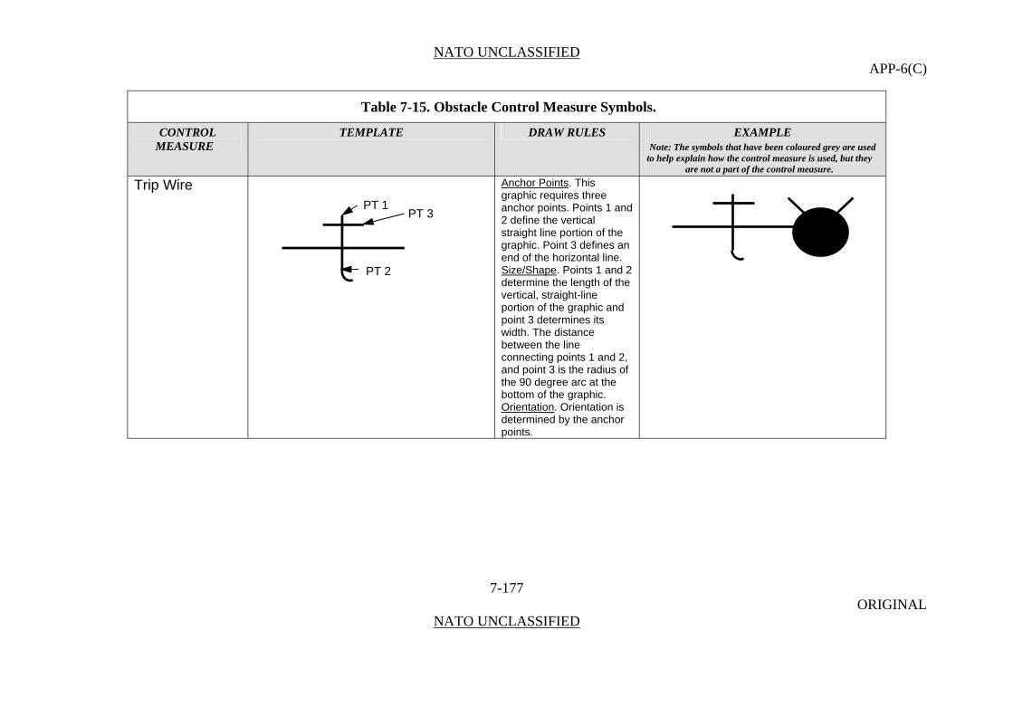
NATO UNCLASSIFIED APP-6(C)
Table 7-15. Obstacle Control Measure Symbols.
CONTROL TEMPLATE DRAW RULES EXAMPLE MEASURE Note: The symbols that have been coloured grey are used
to help explain how the control measure is used, but they are not a part of the control measure.
Trip Wire Anchor Points. This graphic requires three anchor points. Points 1 and 2 define the vertical straight line portion of the graphic. Point 3 defines an end of the horizontal line.
7-177 ORIGINAL
NATO UNCLASSIFIED
PT 3
PT 1
PT 2
Size/Shape. Points 1 and 2 determine the length of the vertical, straight-line portion of the graphic and point 3 determines its width. The distance between the line connecting points 1 and 2, and point 3 is the radius of the 90 degree arc at the bottom of the graphic. Orientation. Orientation is determined by the anchor points.

NATO UNCLASSIFIED APP-6(C)
Table 7-15. Obstacle Control Measure Symbols.
CONTROL TEMPLATE DRAW RULES EXAMPLE MEASURE Note: The symbols that have been coloured grey are used
to help explain how the control measure is used, but they are not a part of the control measure.
Booby Trap Anchor Points. This graphic requires one anchor point. The centre point defines the centre of the circle.
7-178 ORIGINAL
NATO UNCLASSIFIED
A device designed, constructed or adapted to kill or injure, which functions when a person disturbs or approaches an apparently harmless object or performs an apparently safe act. (AAP-6)
Size/Shape. Static. Orientation. The graphic is typically centred over the desired location.
CENTRE POINT
Minefield In land mine warfare, a defined area in which mines have been emplaced. (AAP-6) Completed Minefield
Anchor Points. This graphic requires one anchor point. The centre point defines the centre of the graphic.
Size/Shape. Static. The A field (graphics) will be filled with the type of mine(s) contained in the minefield (see mine types listed in this appendix). If only scatterable mines are
+SH
A
032400ZJUL07 W
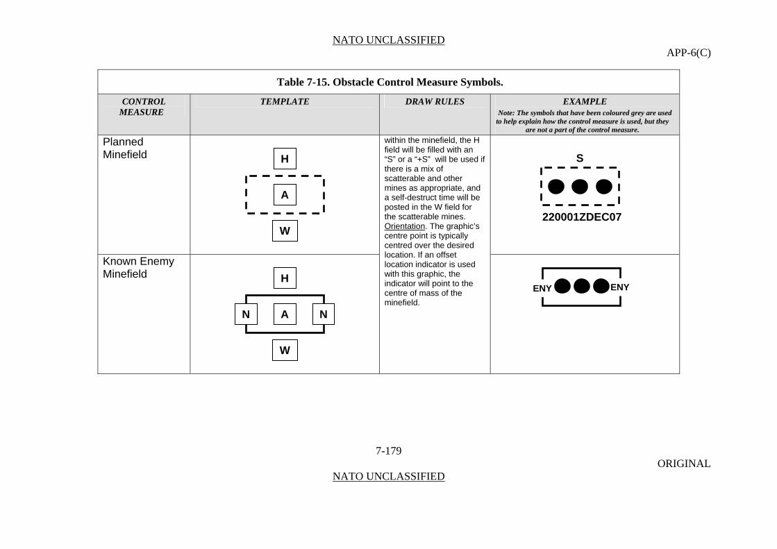
NATO UNCLASSIFIED APP-6(C)
Table 7-15. Obstacle Control Measure Symbols.
CONTROL TEMPLATE DRAW RULES EXAMPLE MEASURE Note: The symbols that have been coloured grey are used
to help explain how the control measure is used, but they are not a part of the control measure.
Planned Minefield
7-179 ORIGINAL
NATO UNCLASSIFIED
within the minefield, the H field will be filled with an “S” or a “+S” will be used if there is a mix of scatterable and other mines as appropriate, and a self-destruct time will be posted in the W field for the scatterable mines.
Known Enemy Minefield
Orientation. The graphic’s centre point is typically centred over the desired location. If an offset location indicator is used with this graphic, the indicator will point to the centre of mass of the minefield.
A
H
W
N N
A
H
W
ENY ENY
S
220001ZDEC07
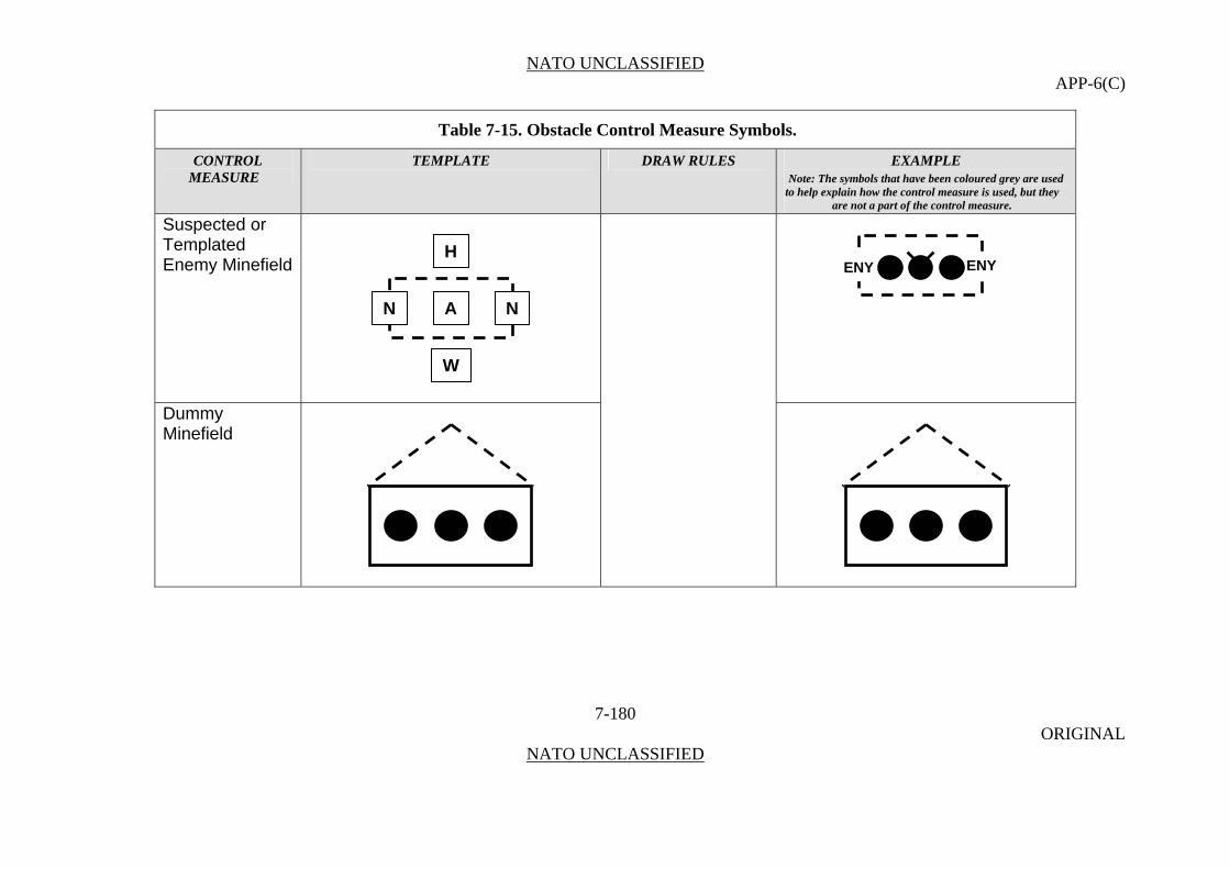
NATO UNCLASSIFIED APP-6(C)
Table 7-15. Obstacle Control Measure Symbols.
CONTROL TEMPLATE DRAW RULES EXAMPLE MEASURE Note: The symbols that have been coloured grey are used
to help explain how the control measure is used, but they are not a part of the control measure.
Suspected or Templated Enemy Minefield
7-180 ORIGINAL
NATO UNCLASSIFIED
Dummy Minefield
HENY ENY
N A N
W

NATO UNCLASSIFIED APP-6(C)
Table 7-15. Obstacle Control Measure Symbols.
CONTROL TEMPLATE DRAW RULES EXAMPLE MEASURE Note: The symbols that have been coloured grey are used
to help explain how the control measure is used, but they are not a part of the control measure.
Mined Area
7-181 ORIGINAL
NATO UNCLASSIFIED
An area which is dangerous because of the presence or suspected presence of mines. (AAP-6)
Anchor Points. This graphic requires at least three anchor points to define the boundary of the area.
Decoy Mined Area
Size/Shape. Determined by the anchor points. The graphic will be filled with the type of mine(s) contained in the minefield (see mine types listed in this appendix). If scatterable mines are within the minefield, the H field will be filled with an “S” or a “+S” as appropriate, and a self-destruct time will be posted in the W field. Orientation. Not applicable.
MH
W
A
M
M
MM M
MM
M
M
M
M
MM M
M
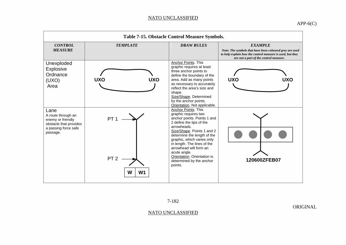
NATO UNCLASSIFIED APP-6(C)
Table 7-15. Obstacle Control Measure Symbols.
CONTROL TEMPLATE DRAW RULES EXAMPLE MEASURE Note: The symbols that have been coloured grey are used
to help explain how the control measure is used, but they are not a part of the control measure.
Unexploded Explosive Ordnance (UXO)
Anchor Points. This graphic requires at least three anchor points to define the boundary of the area. Add as many points as necessary to accurately reflect the area’s size and shape.
7-182 ORIGINAL
NATO UNCLASSIFIED
Area
Size/Shape. Determined by the anchor points. Orientation. Not applicable.
Lane A route through an enemy or friendly obstacle that provides a passing force safe passage.
Anchor Points. This graphic requires two anchor points. Points 1 and 2 define the tips of the arrowheads. Size/Shape. Points 1 and 2 determine the length of the graphic, which varies only in length. The lines of the arrowhead will form an acute angle. Orientation. Orientation is determined by the anchor points.
UXO UXO UXO UXO
PT 1
PT 2 120600ZFEB07
W W1

NATO UNCLASSIFIED APP-6(C)
Table 7-15. Obstacle Control Measure Symbols.
CONTROL TEMPLATE DRAW RULES EXAMPLE MEASURE Note: The symbols that have been coloured grey are used
to help explain how the control measure is used, but they are not a part of the control measure.
Gap Anchor Points. This graphic requires four points. Points 1 and 2 define one side of the gap and points 3 and 4 define the opposite side of the gap.
An area within a minefield or obstacle belt, free of live mines or obstacles, whose width and direction will allow a friendly force to pass through in tactical formation.
Size/Shape. Determined by the anchor points. Orientation. Not applicable.
7-183 ORIGINAL
NATO UNCLASSIFIED

NATO UNCLASSIFIED APP-6(C)
Table 7-15. Obstacle Control Measure Symbols.
CONTROL TEMPLATE DRAW RULES EXAMPLE MEASURE Note: The symbols that have been coloured grey are used
to help explain how the control measure is used, but they are not a part of the control measure.
Roadblocks, Craters, and Blown Bridges Crater obstacle – An obstacle consisting of one or more craters, created normally in a roadway using demolitions. Planned
7-184 ORIGINAL
NATO UNCLASSIFIED
Anchor Points. This graphic requires three anchor points. Points 1 and 2 define the endpoints of the graphic, and point 3 defines the location of one side of the graphic.
Explosives, State of Readiness 1 (Safe)
Size/Shape. Points 1 and 2 determine the centreline of the graphic, and point 3 determines its width. Orientation. Orientation is determined by the anchor points.
PT 1
PT 3
PT 2
PT 1
PT 3
PT 2
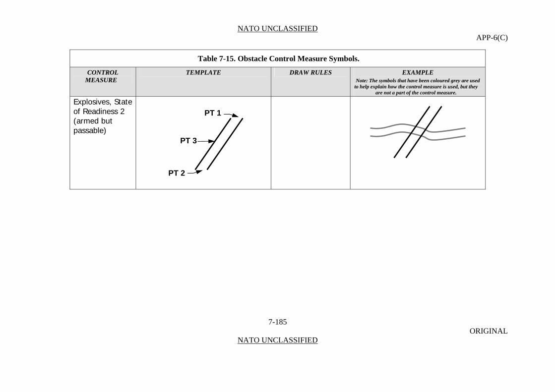
NATO UNCLASSIFIED APP-6(C)
Table 7-15. Obstacle Control Measure Symbols.
CONTROL TEMPLATE DRAW RULES EXAMPLE MEASURE Note: The symbols that have been coloured grey are used
to help explain how the control measure is used, but they are not a part of the control measure.
Explosives, State of Readiness 2 (armed but passable)
7-185 ORIGINAL
NATO UNCLASSIFIED
PT 1
PT 3
PT 2

NATO UNCLASSIFIED APP-6(C)
Table 7-15. Obstacle Control Measure Symbols.
CONTROL TEMPLATE DRAW RULES EXAMPLE MEASURE Note: The symbols that have been coloured grey are used
to help explain how the control measure is used, but they are not a part of the control measure.
Anchor Points
7-186 ORIGINAL
NATO UNCLASSIFIED
Roadblock Complete (Executed)
. This graphic requires three anchor points. Points 1 and 2 define the endpoints of the graphic, and point 3 defines the location of one side of the graphic.
Size/Shape. Points 1 and 2 determine the centreline of one set of the graphic’s parallel lines, and point 3 determines their width. The additional set of parallel lines stays proportional to the first set, and crosses the first set at the centre point of the overall graphic. Orientation. Orientation is detemined by the anchor points.
PT 1
PT 3
PT 2
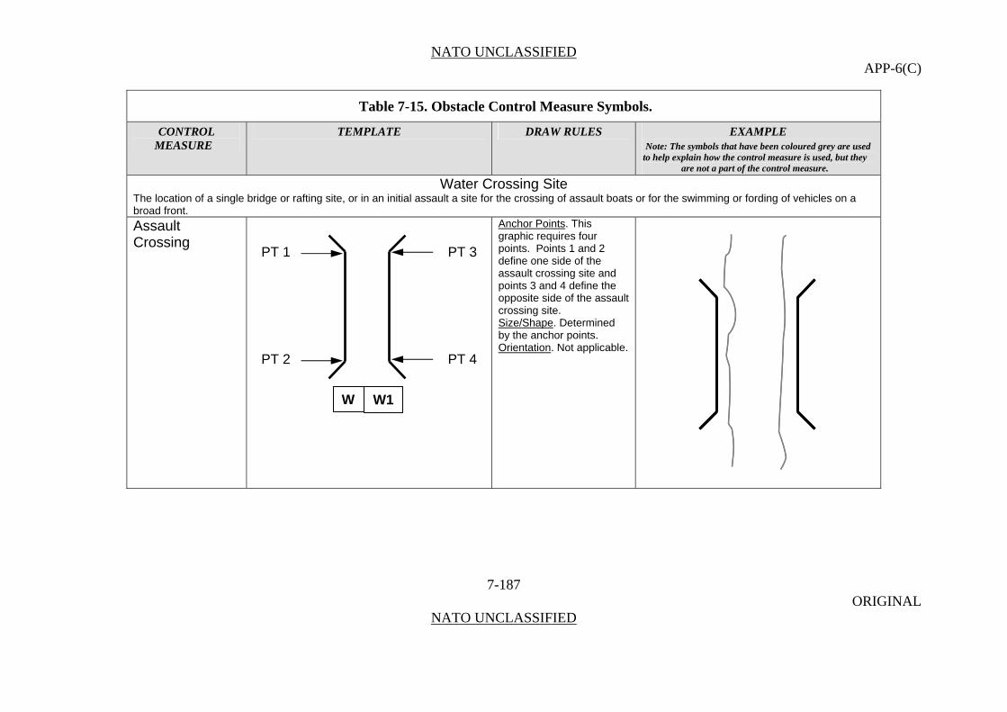
NATO UNCLASSIFIED APP-6(C)
Table 7-15. Obstacle Control Measure Symbols.
CONTROL TEMPLATE DRAW RULES EXAMPLE MEASURE Note: The symbols that have been coloured grey are used
to help explain how the control measure is used, but they are not a part of the control measure.
Water Crossing Site The location of a single bridge or rafting site, or in an initial assault a site for the crossing of assault boats or for the swimming or fording of vehicles on a broad front. Assault Crossing
Anchor Points. This graphic requires four points. Points 1 and 2 define one side of the assault crossing site and points 3 and 4 define the opposite side of the assault crossing site.
7-187 ORIGINAL
NATO UNCLASSIFIED
Size/Shape. Determined by the anchor points. Orientation. Not applicable.
PT 1 PT 3
PT 2 PT 4
W W1
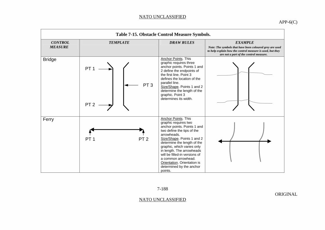
NATO UNCLASSIFIED APP-6(C)
Table 7-15. Obstacle Control Measure Symbols.
CONTROL TEMPLATE DRAW RULES EXAMPLE MEASURE Note: The symbols that have been coloured grey are used
to help explain how the control measure is used, but they are not a part of the control measure.
Bridge Anchor Points. This graphic requires three anchor points. Points 1 and 2 define the endpoints of the first line. Point 3 defines the location of the parallel line.
7-188 ORIGINAL
NATO UNCLASSIFIED
Size/Shape. Points 1 and 2 determine the length of the graphic. Point 3 determines its width.
Ferry
Anchor Points. This graphic requires two anchor points. Points 1 and two define the tips of the arrowheads. Size/Shape. Points 1 and 2 determine the length of the graphic, which varies only in length. The arrowheads will be filled-in versions of a common arrowhead. Orientation. Orientation is determined by the anchor points.
PT 1 PT 2
PT 1
PT 3
PT 2
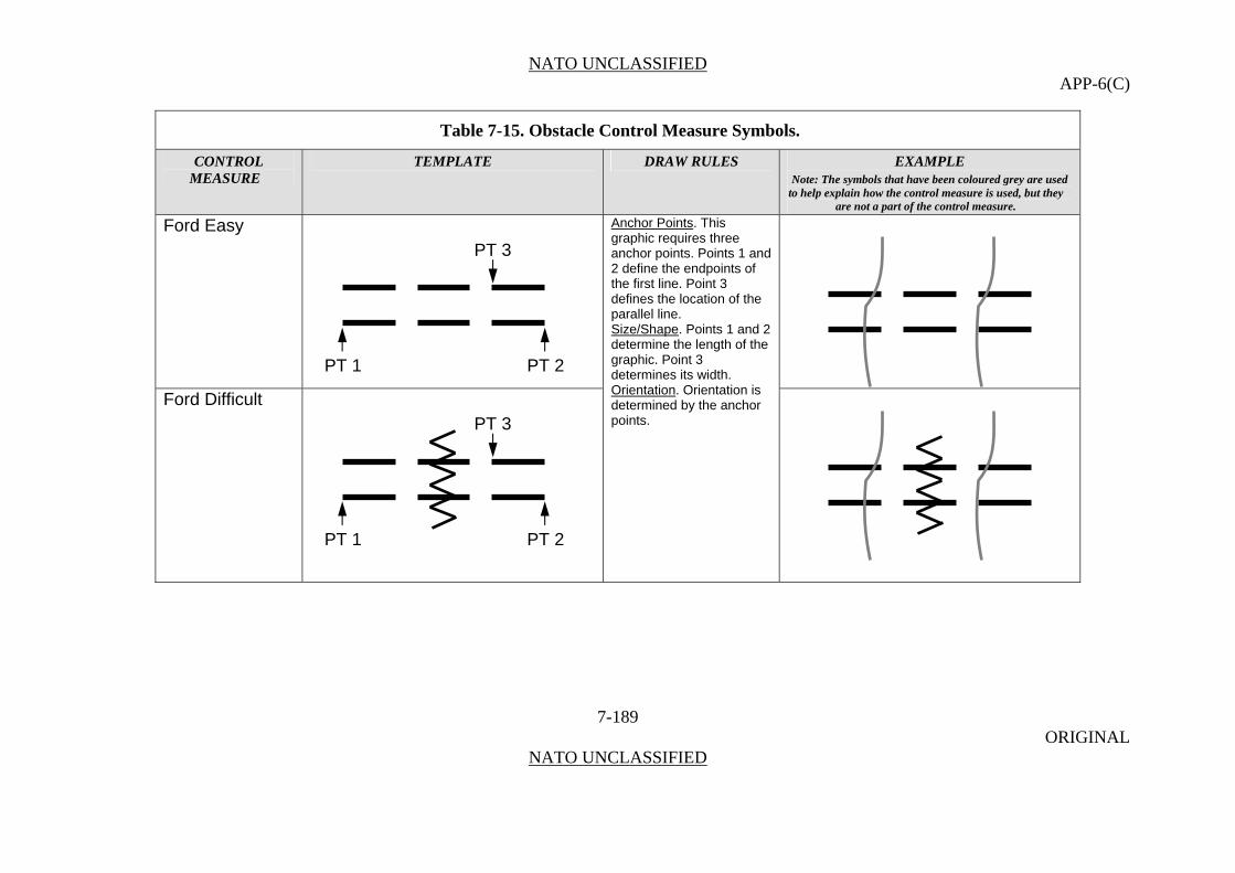
NATO UNCLASSIFIED APP-6(C)
Table 7-15. Obstacle Control Measure Symbols.
CONTROL TEMPLATE DRAW RULES EXAMPLE MEASURE Note: The symbols that have been coloured grey are used
to help explain how the control measure is used, but they are not a part of the control measure.
Ford Easy
7-189 ORIGINAL
NATO UNCLASSIFIED
Anchor Points. This graphic requires three anchor points. Points 1 and 2 define the endpoints of the first line. Point 3 defines the location of the parallel line.
Ford Difficult
Size/Shape. Points 1 and 2 determine the length of the graphic. Point 3 determines its width. Orientation. Orientation is determined by the anchor points.
PT 3
PT 1 PT 2
PT 3
PT 1 PT 2

NATO UNCLASSIFIED APP-6(C)
Table 7-15. Obstacle Control Measure Symbols.
CONTROL TEMPLATE DRAW RULES EXAMPLE MEASURE Note: The symbols that have been coloured grey are used
to help explain how the control measure is used, but they are not a part of the control measure.
Raft Site Anchor Points. This graphic requires two anchor points. Points 1 and 2 define the tips of the arrowheads.
7-190 ORIGINAL
NATO UNCLASSIFIED
Size/Shape. Points 1 and 2 determine the length of the graphic, which varies only in length. The lines of the arrowhead will form an acute angle. Orientation. Orientation is determined by the anchor points.
Engineer Regulating Point Checkpoint to ensure that vehicles do not exceed the capacity of the crossing means and to give drivers final instructions on site-specific procedures and information, such as speed and vehicle interval.
Anchor Points. This graphic requires one anchor point. The point defines the tip of the inverted cone. Size/Shape. Static. Orientation. The graphic will typically be oriented upright, as shown in the example to the right.
PT 1
PT 2
8H
ERP
T
TW
W1
ANCHORPOINT
ERP

NATO UNCLASSIFIED APP-6(C)
Field Fortification Obstacle Control Measures
0721. A field fortification is an emplacement or shelter of a temporary nature which can be constructed with reasonable facility by units requiring no more than minor engineer supervisory and equipment participation. (AAP-6)
Table 7-16. Field Fortification Control Measure Symbols.
CONTROL TEMPLATE DRAW RULES EXAMPLE MEASURE Note: The symbols that have been coloured grey are used
to help explain how the control measure is used, but they are not a part of the control measure.
Points Shelter
7-191 ORIGINAL
NATO UNCLASSIFIED
Anchor Points. This graphic requires one anchor point. The centre point defines the centre of the circle.
Above Ground Shelter
Size/Shape. Static. Orientation. The graphic is typically centred over the desired location.
CENTRE POINT
CENTRE POINT
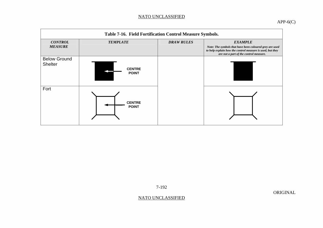
NATO UNCLASSIFIED APP-6(C)
Table 7-16. Field Fortification Control Measure Symbols.
CONTROL TEMPLATE DRAW RULES EXAMPLE MEASURE Note: The symbols that have been coloured grey are used
to help explain how the control measure is used, but they are not a part of the control measure.
Below Ground Shelter
7-192 ORIGINAL
NATO UNCLASSIFIED
CENTRE POINT
Fort
CENTRE POINT
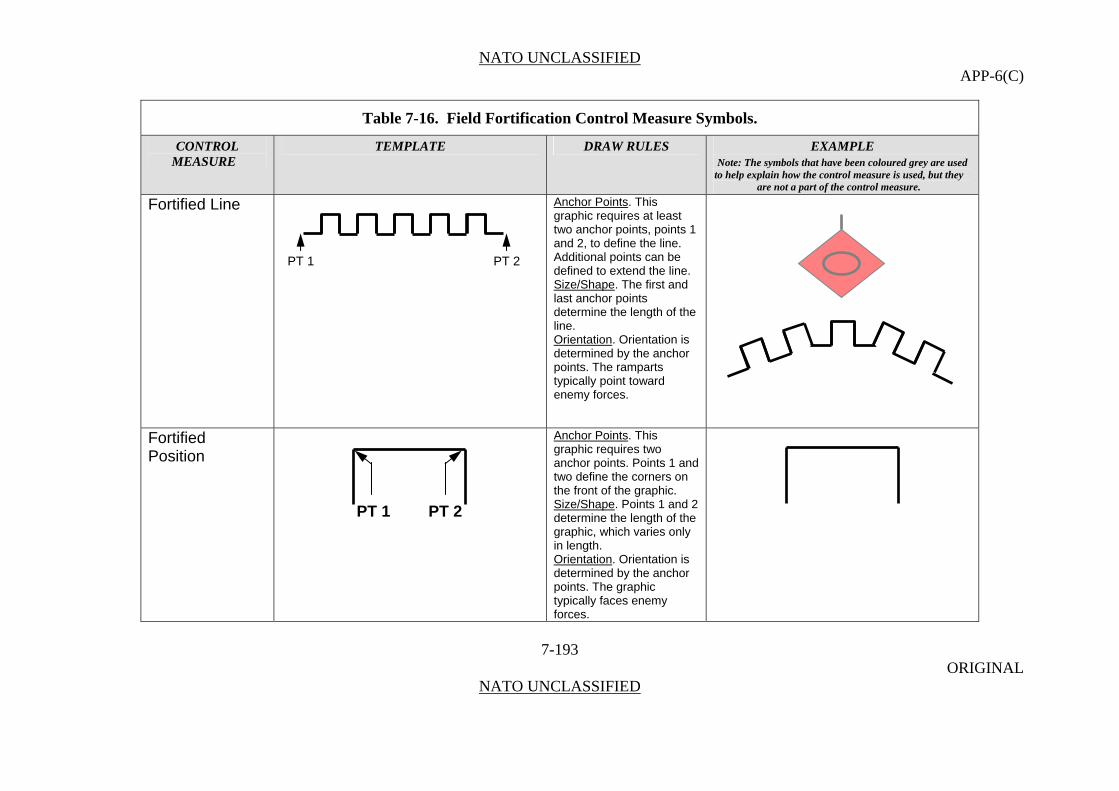
NATO UNCLASSIFIED APP-6(C)
Table 7-16. Field Fortification Control Measure Symbols.
CONTROL TEMPLATE DRAW RULES EXAMPLE MEASURE Note: The symbols that have been coloured grey are used
to help explain how the control measure is used, but they are not a part of the control measure.
Fortified Line Anchor Points. This graphic requires at least two anchor points, points 1 and 2, to define the line.
7-193 ORIGINAL
NATO UNCLASSIFIED
Additional points can be defined to extend the line. Size/Shape. The first and last anchor points determine the length of the line. Orientation. Orientation is determined by the anchor points. The ramparts typically point toward enemy forces.
Fortified Position
Anchor Points. This graphic requires two anchor points. Points 1 and two define the corners on the front of the graphic. Size/Shape. Points 1 and 2 determine the length of the graphic, which varies only in length. Orientation. Orientation is determined by the anchor points. The graphic typically faces enemy forces.
PT 1 PT 2
PT 1 PT 2

NATO UNCLASSIFIED APP-6(C)
7-194 ORIGINAL
NATO UNCLASSIFIED

NATO UNCLASSIFIED APP-6(C)
Chemical, Biological, Radiological and Nuclear Attacks and Events
0722. These control measure symbols depict those conditions found in an area resulting from immediate or persisting effects of chemical, biological, radiological or nuclear attacks or events (release other than attack).
Table 7-17. CBRN Defence Control Measure Symbols.
CONTROL TEMPLATE DRAW RULES EXAMPLE MEASURE Note: The symbols that have been coloured grey are used
to help explain how the control measure is used, but they are not a part of the control measure.
Chemical Anchor Points. This graphic requires one anchor point. The anchor point defines the midpoint of the graphic’s base.
7-195 ORIGINAL
NATO UNCLASSIFIED
Size/Shape. Static. Orientation. The graphic will typically be oriented upright, as shown in the example to the right, but can be rotated in 90 degree increments.
300700ZJUN08
CANNISTER
NERVE AGENT
HS10211948
3
ENY
300700ZJUN08
CANNISTER
NERVE AGENT
HS10211948
3
ENY
C
W H
T N
YANCHORPOINT
Q
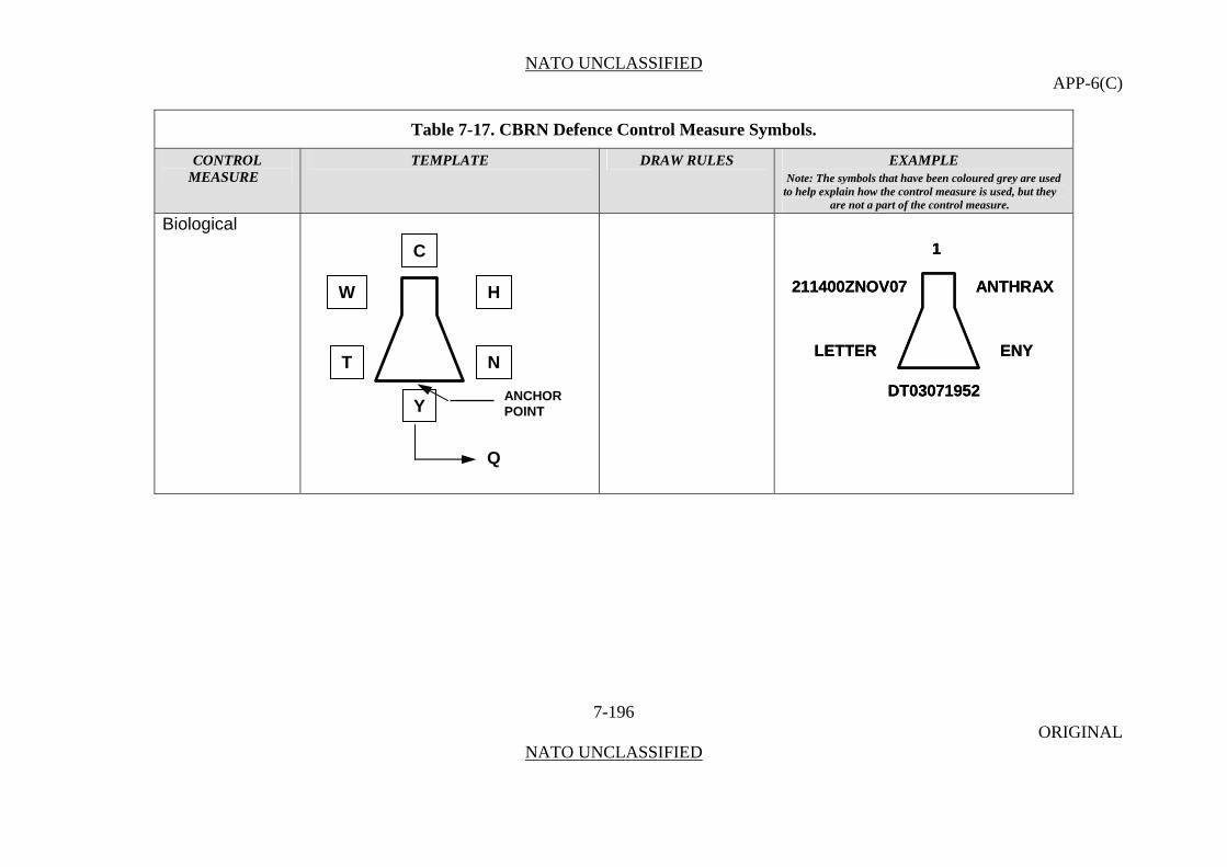
NATO UNCLASSIFIED APP-6(C)
Table 7-17. CBRN Defence Control Measure Symbols.
CONTROL TEMPLATE DRAW RULES EXAMPLE MEASURE Note: The symbols that have been coloured grey are used
to help explain how the control measure is used, but they are not a part of the control measure.
Biological
7-196 ORIGINAL
NATO UNCLASSIFIED
211400ZNOV07
LETTER
ANTHRAX
ENY
DT03071952
1
211400ZNOV07
LETTER
ANTHRAX
ENY
DT03071952
1C
W H
T N
YANCHORPOINT
Q
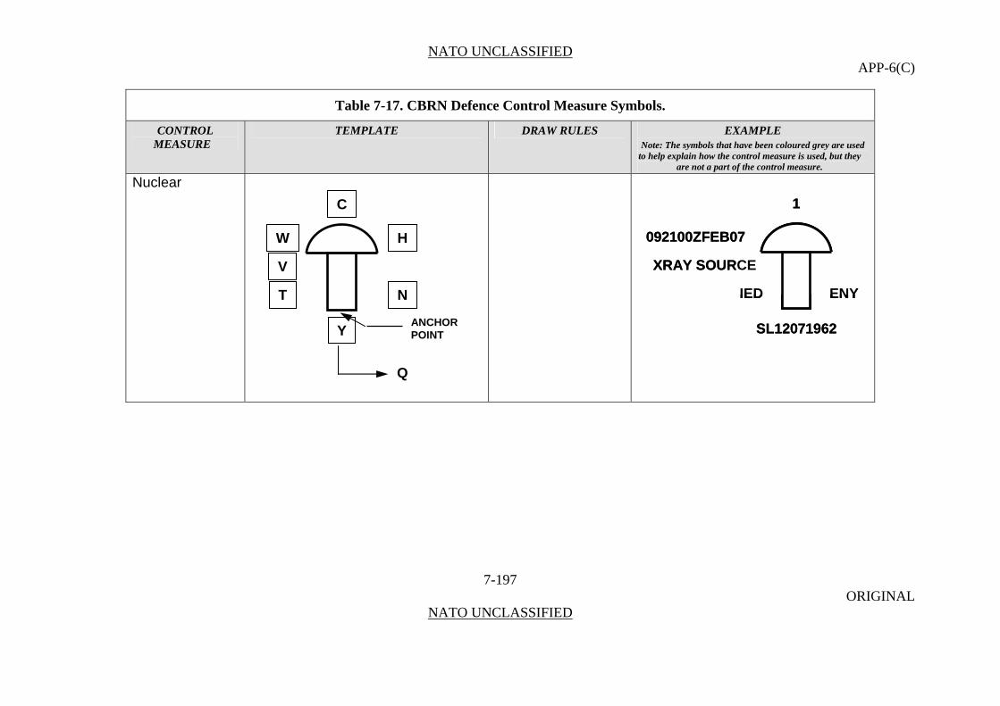
NATO UNCLASSIFIED APP-6(C)
Table 7-17. CBRN Defence Control Measure Symbols.
CONTROL TEMPLATE DRAW RULES EXAMPLE MEASURE Note: The symbols that have been coloured grey are used
to help explain how the control measure is used, but they are not a part of the control measure.
Nuclear
7-197 ORIGINAL
NATO UNCLASSIFIED
092100ZFEB07
XRAY SOURCE
IED ENY
SL12071962
1
092100ZFEB07
XRAY SOURCE
IED ENY
SL12071962
1C
W H
V
T N
YANCHORPOINT
Q
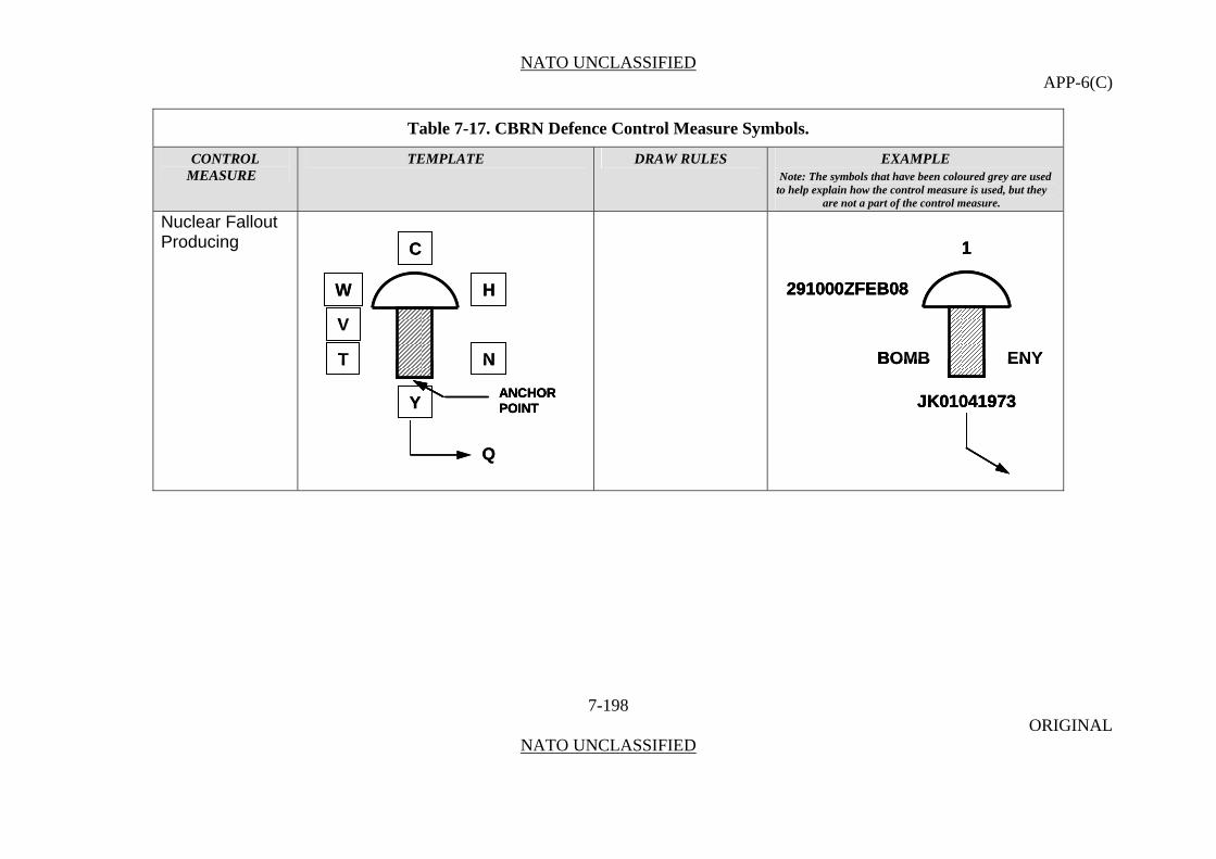
NATO UNCLASSIFIED APP-6(C)
Table 7-17. CBRN Defence Control Measure Symbols.
CONTROL TEMPLATE DRAW RULES EXAMPLE MEASURE Note: The symbols that have been coloured grey are used
to help explain how the control measure is used, but they are not a part of the control measure.
Nuclear Fallout Producing
W
V
T
H
N
Y
C
Q
ANCHORPOINT
W
V
T
H
N
Y
C
Q
ANCHORPOINTANCHORPOINT
291000ZFEB08
BOMB ENY
JK01041973
1
291000ZFEB08
BOMB ENY
JK01041973
1
291000ZFEB08
BOMB ENY
JK01041973
1
7-198 ORIGINAL
NATO UNCLASSIFIED
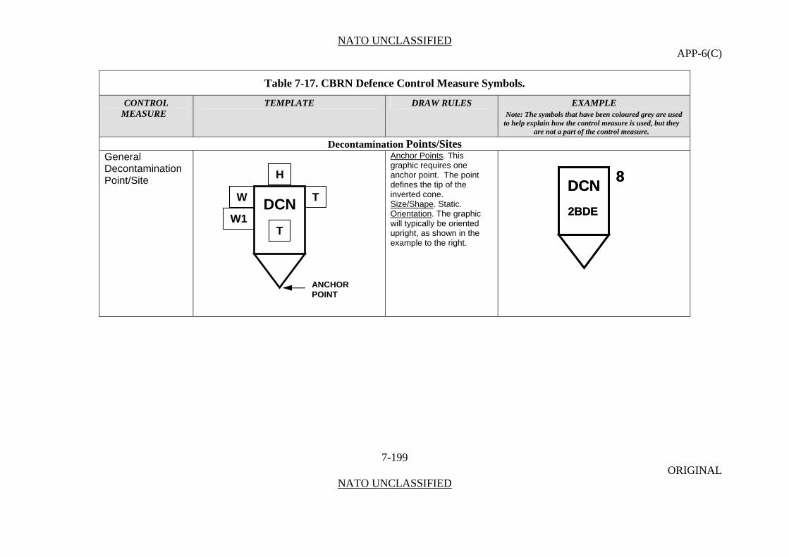
NATO UNCLASSIFIED APP-6(C)
Table 7-17. CBRN Defence Control Measure Symbols.
CONTROL TEMPLATE DRAW RULES EXAMPLE MEASURE Note: The symbols that have been coloured grey are used
to help explain how the control measure is used, but they are not a part of the control measure.
Decontamination Points/Sites General
Decontamination Point/Site
Anchor Points. This graphic requires one anchor point. The point defines the tip of the inverted cone.
7-199 ORIGINAL
NATO UNCLASSIFIED
Size/Shape. Static. Orientation. The graphic will typically be oriented upright, as shown in the example to the right.
DCN
2BDE
8DCN
2BDE
8
H
DCN W T
W1T
ANCHORPOINT

NATO UNCLASSIFIED APP-6(C)
Table 7-17. CBRN Defence Control Measure Symbols.
CONTROL TEMPLATE DRAW RULES EXAMPLE MEASURE Note: The symbols that have been coloured grey are used
to help explain how the control measure is used, but they are not a part of the control measure.
Alternate Decontamination Point/Site
7-200 ORIGINAL
NATO UNCLASSIFIED
DCNALT
6ABB
8ADCNALT
6ABB
8A
H
W TDCNALTW1
T
ANCHORPOINT

NATO UNCLASSIFIED APP-6(C)
Table 7-17. CBRN Defence Control Measure Symbols.
CONTROL TEMPLATE DRAW RULES EXAMPLE MEASURE Note: The symbols that have been coloured grey are used
to help explain how the control measure is used, but they are not a part of the control measure.
Equipment Decontamination Point/Site
7-201 ORIGINAL
NATO UNCLASSIFIED
WHEELED
DCNE
41CB
L
WHEELED
DCNE
41CB
DCNE
41CB
L
H
W TDCNE W1
T
ANCHORPOINT

NATO UNCLASSIFIED APP-6(C)
Table 7-17. CBRN Defence Control Measure Symbols.
CONTROL TEMPLATE DRAW RULES EXAMPLE MEASURE Note: The symbols that have been coloured grey are used
to help explain how the control measure is used, but they are not a part of the control measure.
Troop Decontamination Point/Site DCN
T
212CB
RC(W)DCNT
212CB
RC(W)
7-202 ORIGINAL
NATO UNCLASSIFIED
H
W TDCNT W1
T
ANCHORPOINT

NATO UNCLASSIFIED APP-6(C)
Table 7-17. CBRN Defence Control Measure Symbols.
CONTROL TEMPLATE DRAW RULES EXAMPLE MEASURE Note: The symbols that have been coloured grey are used
to help explain how the control measure is used, but they are not a part of the control measure.
Equipment/Troop Decontamination Point/Site
7-203 ORIGINAL
NATO UNCLASSIFIED
CONTRACTOROPERATED
DCNE/T
DEU
MND(S)210700ZAPR08
071800ZMAY08
CONTRACTOROPERATED
DCNE/T
DEU
DCNE/T
DEU
MND(S)210700ZAPR08
071800ZMAY08
H
W TDCNE/TW1
T
ANCHORPOINT

NATO UNCLASSIFIED APP-6(C)
Table 7-17. CBRN Defence Control Measure Symbols.
CONTROL TEMPLATE DRAW RULES EXAMPLE MEASURE Note: The symbols that have been coloured grey are used
to help explain how the control measure is used, but they are not a part of the control measure.
Operational Decontamination Point/Site
7-204 ORIGINAL
NATO UNCLASSIFIED
DCNO
ACO
VDCNO
DCNO
ACO
V
H
W TDCNO W1
T
ANCHORPOINT
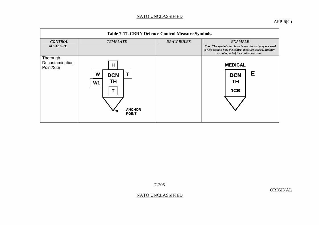
NATO UNCLASSIFIED APP-6(C)
Table 7-17. CBRN Defence Control Measure Symbols.
CONTROL TEMPLATE DRAW RULES EXAMPLE MEASURE Note: The symbols that have been coloured grey are used
to help explain how the control measure is used, but they are not a part of the control measure.
Thorough Decontamination Point/Site
7-205 ORIGINAL
NATO UNCLASSIFIED
MEDICAL
DCNTH
1CB
E
MEDICAL
DCNTH
1CB
DCNTH
1CB
E
H
W TDCNTH W1
T
ANCHORPOINT
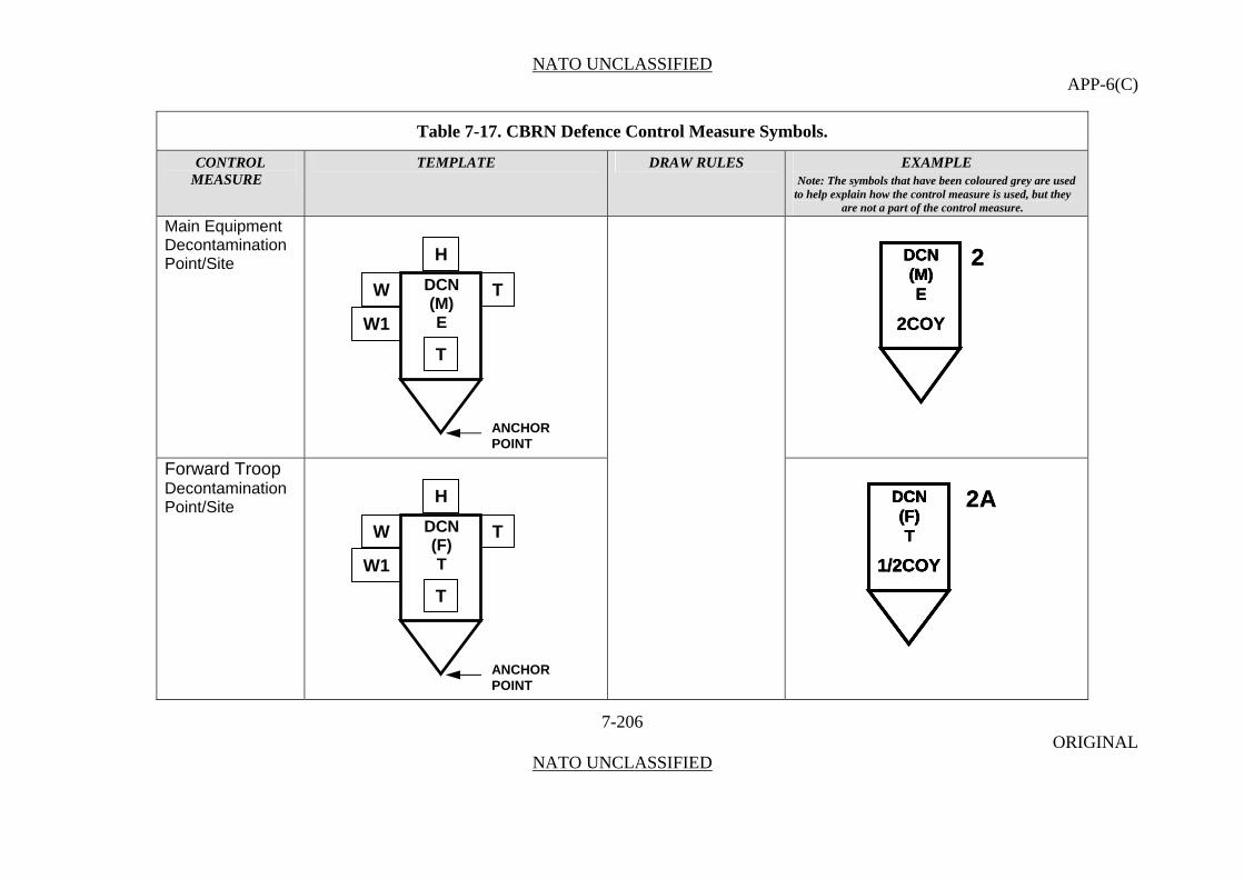
NATO UNCLASSIFIED APP-6(C)
Table 7-17. CBRN Defence Control Measure Symbols.
CONTROL TEMPLATE DRAW RULES EXAMPLE MEASURE Note: The symbols that have been coloured grey are used
to help explain how the control measure is used, but they are not a part of the control measure.
7-206 ORIGINAL
NATO UNCLASSIFIED
Main Equipment Decontamination Point/Site
DCN(M)E
2COY
2DCN(M)E
DCN(M)E
2COY
2
Forward Troop Decontamination Point/Site
DCN(F)T
1/2COY
2ADCN(F)T
1/2COY
DCN(F)T
DCN(F)T
1/2COY
2A
H
DCNW T(M)E W1
T
ANCHORPOINT
H
DCNW T(F) T W1
T
ANCHORPOINT

NATO UNCLASSIFIED APP-6(C)
Table 7-17. CBRN Defence Control Measure Symbols.
CONTROL TEMPLATE DRAW RULES EXAMPLE MEASURE Note: The symbols that have been coloured grey are used
to help explain how the control measure is used, but they are not a part of the control measure.
Wounded Personnel Decontamination Site
DCNW
H
T
TW
W1
ANCHORPOINT
DCNW
H
T
TW
W1
W
W1
ANCHORPOINTANCHORPOINT
Contaminated Areas
Biologically Contaminated Area
Anchor Points. This graphic requires at least three anchor points to define the boundary of the area. Add as many points as necessary to accurately reflect the area’s size and shape. Size/Shape. Determined by the anchor points. The graphic should be moveable within the area.
Orientation. Not applicable.
7-207 ORIGINAL
NATO UNCLASSIFIED

NATO UNCLASSIFIED APP-6(C)
Table 7-17. CBRN Defence Control Measure Symbols.
CONTROL TEMPLATE DRAW RULES EXAMPLE MEASURE Note: The symbols that have been coloured grey are used
to help explain how the control measure is used, but they are not a part of the control measure.
Chemical Contaminated Area
7-208 ORIGINAL
NATO UNCLASSIFIED
Radioactive Contaminated Area
N N
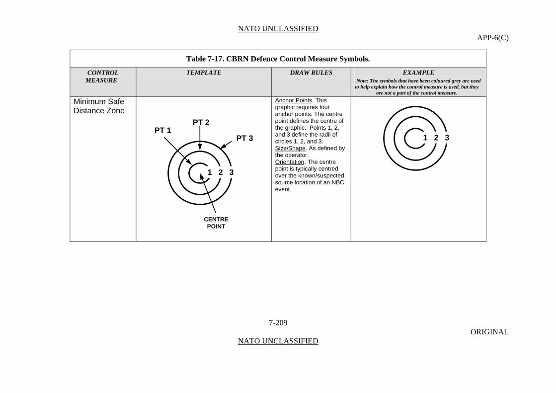
NATO UNCLASSIFIED APP-6(C)
Table 7-17. CBRN Defence Control Measure Symbols.
CONTROL TEMPLATE DRAW RULES EXAMPLE MEASURE Note: The symbols that have been coloured grey are used
to help explain how the control measure is used, but they are not a part of the control measure.
Minimum Safe Distance Zone
Anchor Points. This graphic requires four anchor points. The centre point defines the centre of the graphic. Points 1, 2, and 3 define the radii of circles 1, 2, and 3.
7-209 ORIGINAL
NATO UNCLASSIFIED
Size/Shape. As defined by the operator. Orientation. The centre point is typically centred over the known/suspected source location of an NBC event.
PT 2 PT 1
1 2 3
1 2 3
PT 3
CENTRE POINT

NATO UNCLASSIFIED APP-6(C)
Table 7-17. CBRN Defence Control Measure Symbols.
CONTROL TEMPLATE DRAW RULES EXAMPLE MEASURE Note: The symbols that have been coloured grey are used
to help explain how the control measure is used, but they are not a part of the control measure.
Radiation Dose Rate Contour Line
Anchor Points. This graphic requires at least three anchor points to define the boundary of the area. Add as many points as necessary to accurately reflect the area’s size and shape.
7-210 ORIGINAL
NATO UNCLASSIFIED
A line on a map, diagram or overlay joining all points at which the radiation dose rate at a given time is the same.
Size/Shape. Determined by the anchor points. Orientation. Not applicable.
30cGy
300cGy
100cGy

NATO UNCLASSIFIED APP-6(C)
Sustainment
Sustainment Control Measures 0723. Sustainment is the provision of logistics and personnel services required to maintain and prolong operations until successful mission accomplishment.
Table7-18. Sustainment Point Control Measure Symbols
CONTROL TEMPLATE DRAW RULES EXAMPLE MEASURE Note: The symbols that have been coloured grey are used
to help explain how the control measure is used, but they are not a part of the control measure.
Points Ambulance Exchange Point
Anchor Points. This graphic requires one anchor point. The point defines the tip of the inverted cone.
7-211 ORIGINAL
NATO UNCLASSIFIED
A location where a patient is transferred from one ambulance to another en route to a medical treatment facility. This may be an established point in an ambulance shuttle system or it may be designated independently.
Size/Shape. Static. Orientation. The graphic will typically be oriented upright, as shown in the example to the right,
AXP
H
T
TW
W1
ANCHORPOINT
1AXP
4077

NATO UNCLASSIFIED APP-6(C)
Table7-18. Sustainment Point Control Measure Symbols
CONTROL TEMPLATE DRAW RULES EXAMPLE MEASURE Note: The symbols that have been coloured grey are used
to help explain how the control measure is used, but they are not a part of the control measure.
Ammunition Supply Point
7-212 ORIGINAL
NATO UNCLASSIFIED
An area designated to receive, store, reconfigure, and issue Class V material.
ASP
MNSE
RC(W)ASP
MNSE
RC(W)
Ammunition Transfer Point A designated temporary site from which Class V material is transferred to unit vehicles.
ATP
RC(C)
4ATP
RC(C)
4
ATP
H
T
TW
W1
ANCHORPOINT
H
W TASP
W1T
ANCHORPOINT
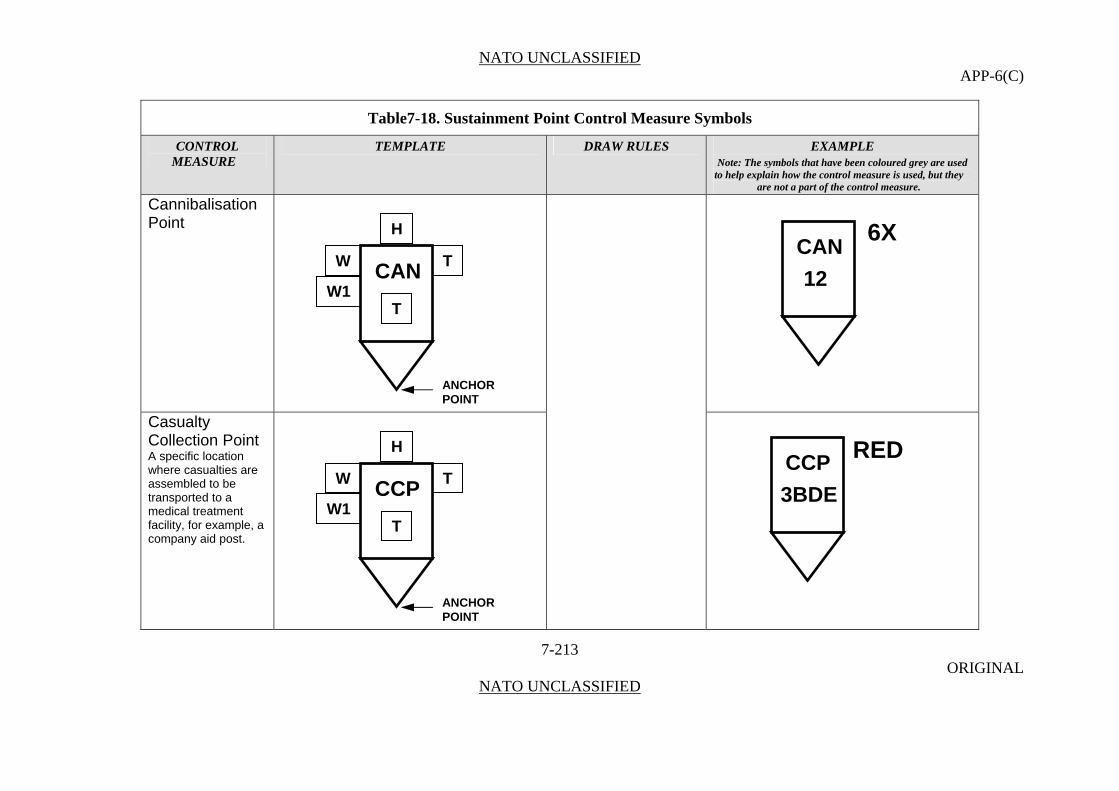
NATO UNCLASSIFIED APP-6(C)
Table7-18. Sustainment Point Control Measure Symbols
CONTROL TEMPLATE DRAW RULES EXAMPLE MEASURE Note: The symbols that have been coloured grey are used
to help explain how the control measure is used, but they are not a part of the control measure.
Cannibalisation Point
7-213 ORIGINAL
NATO UNCLASSIFIED
Casualty Collection Point A specific location where casualties are assembled to be transported to a medical treatment facility, for example, a company aid post.
CCP
H
T
TW
W1
ANCHORPOINT
CAN
H
T
TW
W1
ANCHORPOINT
6XCAN
12
RED CCP
3BDE
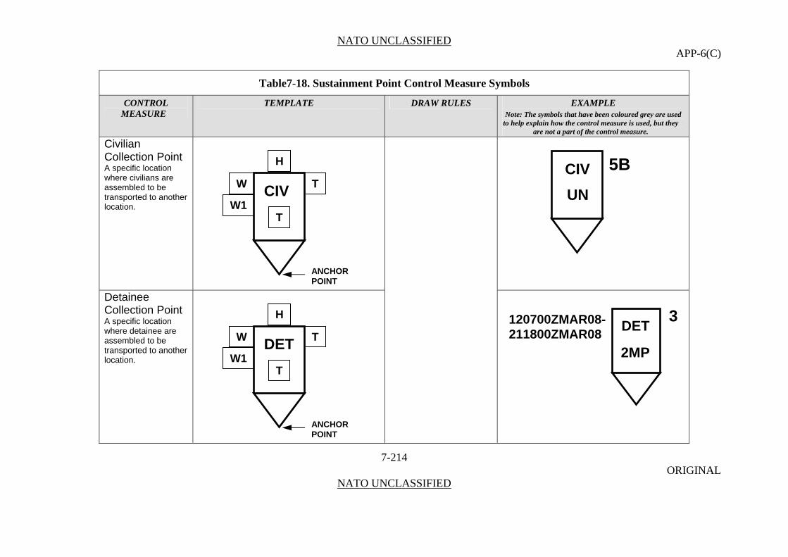
NATO UNCLASSIFIED APP-6(C)
Table7-18. Sustainment Point Control Measure Symbols
CONTROL TEMPLATE DRAW RULES EXAMPLE MEASURE Note: The symbols that have been coloured grey are used
to help explain how the control measure is used, but they are not a part of the control measure.
Civilian Collection Point
7-214 ORIGINAL
NATO UNCLASSIFIED
A specific location where civilians are assembled to be transported to another location.
Detainee Collection Point A specific location where detainee are assembled to be transported to another location.
CIV
H
T
TW
W1
ANCHORPOINT
DET
H
T
TW
W1
ANCHORPOINT
5BCIV
UN
3120700ZMAR08- DET 211800ZMAR08
2MP
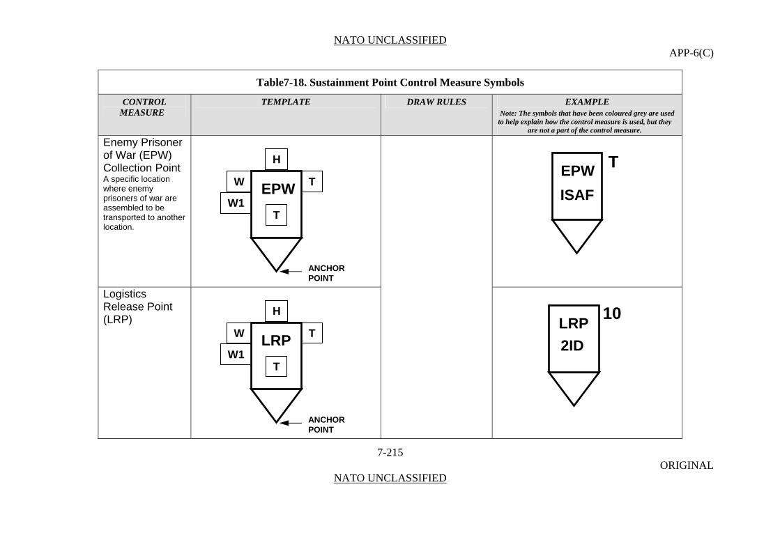
NATO UNCLASSIFIED APP-6(C)
Table7-18. Sustainment Point Control Measure Symbols
CONTROL TEMPLATE DRAW RULES EXAMPLE MEASURE Note: The symbols that have been coloured grey are used
to help explain how the control measure is used, but they are not a part of the control measure.
Enemy Prisoner of War (EPW) Collection Point
7-215 ORIGINAL
NATO UNCLASSIFIED
A specific location where enemy prisoners of war are assembled to be transported to another location.
Logistics Release Point (LRP)
EPW
H
T
TW
W1
ANCHORPOINT
LRP
H
T
TW
W1
ANCHORPOINT
TEPW
ISAF
10LRP
2ID

NATO UNCLASSIFIED APP-6(C)
Table7-18. Sustainment Point Control Measure Symbols
CONTROL TEMPLATE DRAW RULES EXAMPLE MEASURE Note: The symbols that have been coloured grey are used
to help explain how the control measure is used, but they are not a part of the control measure.
Maintenance Collection Point (MCP)
7-216 ORIGINAL
NATO UNCLASSIFIED
A point established to collect equipment awaiting repair, controlled exchange, cannibalisation, or evacuation. It may be operated by the user or by the direct support maintenance units.
MCP
RC(E)
NMCP
RC(E)
N
Rearm, Refuel, and Resupply Point (R3P) A designated point through which a unit passes where it receives fuel, ammunition, and other necessary supplies to continue operations.
R3P
1
CR3P
1
C
H
MCP W T
W1T
ANCHORPOINT
H
W TR3P
W1T
ANCHORPOINT
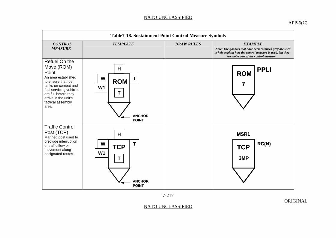
NATO UNCLASSIFIED APP-6(C)
Table7-18. Sustainment Point Control Measure Symbols
CONTROL TEMPLATE DRAW RULES EXAMPLE MEASURE Note: The symbols that have been coloured grey are used
to help explain how the control measure is used, but they are not a part of the control measure.
Refuel On the Move (ROM) Point
7-217 ORIGINAL
NATO UNCLASSIFIED
An area established to ensure that fuel tanks on combat and fuel servicing vehicles are full before they arrive in the unit’s tactical assembly area.
ROM
7
PPLIROM
7
PPLI
Traffic Control Post (TCP) Manned post used to preclude interruption of traffic flow or movement along designated routes.
TCP
MSR1
3MP
RC(N)TCP
MSR1
3MP
RC(N)
H
ROM W T
W1T
ANCHORPOINT
H
W TTCP
W1T
ANCHORPOINT

NATO UNCLASSIFIED APP-6(C)
Table7-18. Sustainment Point Control Measure Symbols
CONTROL TEMPLATE DRAW RULES EXAMPLE MEASURE Note: The symbols that have been coloured grey are used
to help explain how the control measure is used, but they are not a part of the control measure.
Trailer Transfer Point (TTP)
7-218 ORIGINAL
NATO UNCLASSIFIED
A location where trailers are transferred from one carrier to another while en route.
TTP
MNSE
7ATTP
MNSE
7A
H
W TTTP
W1T
ANCHORPOINT
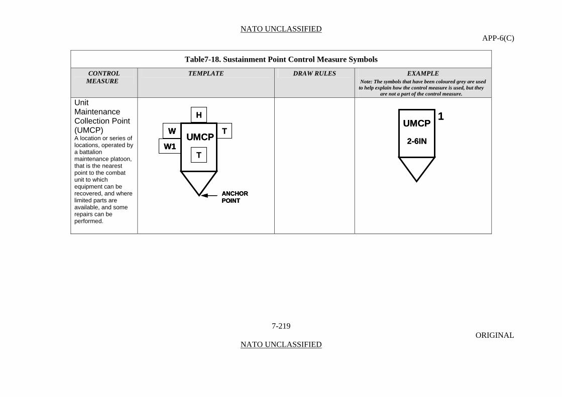
NATO UNCLASSIFIED APP-6(C)
Table7-18. Sustainment Point Control Measure Symbols
CONTROL TEMPLATE DRAW RULES EXAMPLE MEASURE Note: The symbols that have been coloured grey are used
to help explain how the control measure is used, but they are not a part of the control measure.
Unit Maintenance Collection Point (UMCP)
UMCP
H
T
TW
W1
ANCHORPOINT
UMCP
H
T
TW
W1
W
W1
ANCHORPOINTANCHORPOINT
UMCP
2-6IN
1UMCP
2-6IN
1
A location or series of locations, operated by a battalion maintenance platoon, that is the nearest point to the combat unit to which equipment can be recovered, and where limited parts are available, and some repairs can be performed.
7-219 ORIGINAL
NATO UNCLASSIFIED

NATO UNCLASSIFIED APP-6(C)
Supply Points
0724. A supply point is any point where supplies are issued in detail. Supply points follow the format as shown above with a modification to the symbol. As with the symbol for supply units, there is an additional line placed toward the bottom of the box. In building points, the name/type of the point is abbreviated and positioned inside the top part of the point symbol in field “A”. For some supply symbols this may be a graphic icon. STANAG 2961 provides comparison charts for NATO and NATO nation classes of supply.
Table 7-19. Supply Point Control Measure Symbols.
CONTROL TEMPLATE DRAW RULES EXAMPLE MEASURE Note: The symbols that have been coloured grey are used
to help explain how the control measure is used, but they are not a part of the control measure.
General Supply Point
Anchor Points. This graphic requires one anchor point. The point defines the tip of the inverted cone.
7-220 ORIGINAL
NATO UNCLASSIFIED
Size/Shape. Static. Orientation. The graphic will typically be oriented upright, as shown in the examples to the right,
H
W T
T
A
W1
ANCHORPOINT

NATO UNCLASSIFIED APP-6(C)
Table 7-19. Supply Point Control Measure Symbols.
CONTROL TEMPLATE DRAW RULES EXAMPLE MEASURE Note: The symbols that have been coloured grey are used
to help explain how the control measure is used, but they are not a part of the control measure.
Class I
7-221 ORIGINAL
NATO UNCLASSIFIED
Those items which are consumed by personnel or animals at the approximately uniform rate, irrespective of local changes in combat or terrain conditions. (STANAG 2961)
I 2
3SUST
I 2
3SUST
I
H
W T
W1A
ANCHORPOINT
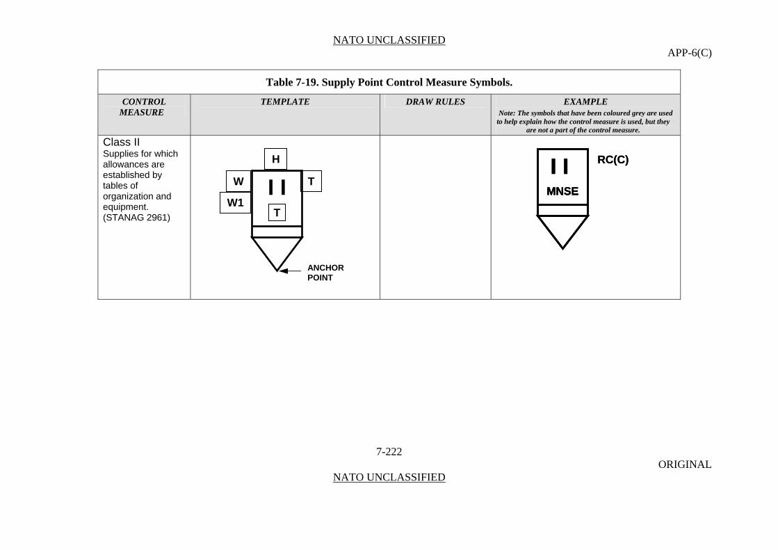
NATO UNCLASSIFIED APP-6(C)
Table 7-19. Supply Point Control Measure Symbols.
CONTROL TEMPLATE DRAW RULES EXAMPLE MEASURE Note: The symbols that have been coloured grey are used
to help explain how the control measure is used, but they are not a part of the control measure.
Class II
RC(C)
MNSE
I I RC(C)
MNSE
I I MNSE
I I Supplies for which allowances are established by tables of organization and equipment. (STANAG 2961)
7-222 ORIGINAL
NATO UNCLASSIFIED
H
TW
W1
ANCHORPOINT
T
I I

NATO UNCLASSIFIED APP-6(C)
Table 7-19. Supply Point Control Measure Symbols.
CONTROL TEMPLATE DRAW RULES EXAMPLE MEASURE Note: The symbols that have been coloured grey are used
to help explain how the control measure is used, but they are not a part of the control measure.
Class III
7-223 ORIGINAL
NATO UNCLASSIFIED
Fuels and lubricants for all purposes, except for operating aircraft or for use in weapons such as flame throwers. (STANAG 2961)
I I I 5S
RC(E)
I I I 5S
RC(E)
I I I
H
W T
W1T
ANCHORPOINT
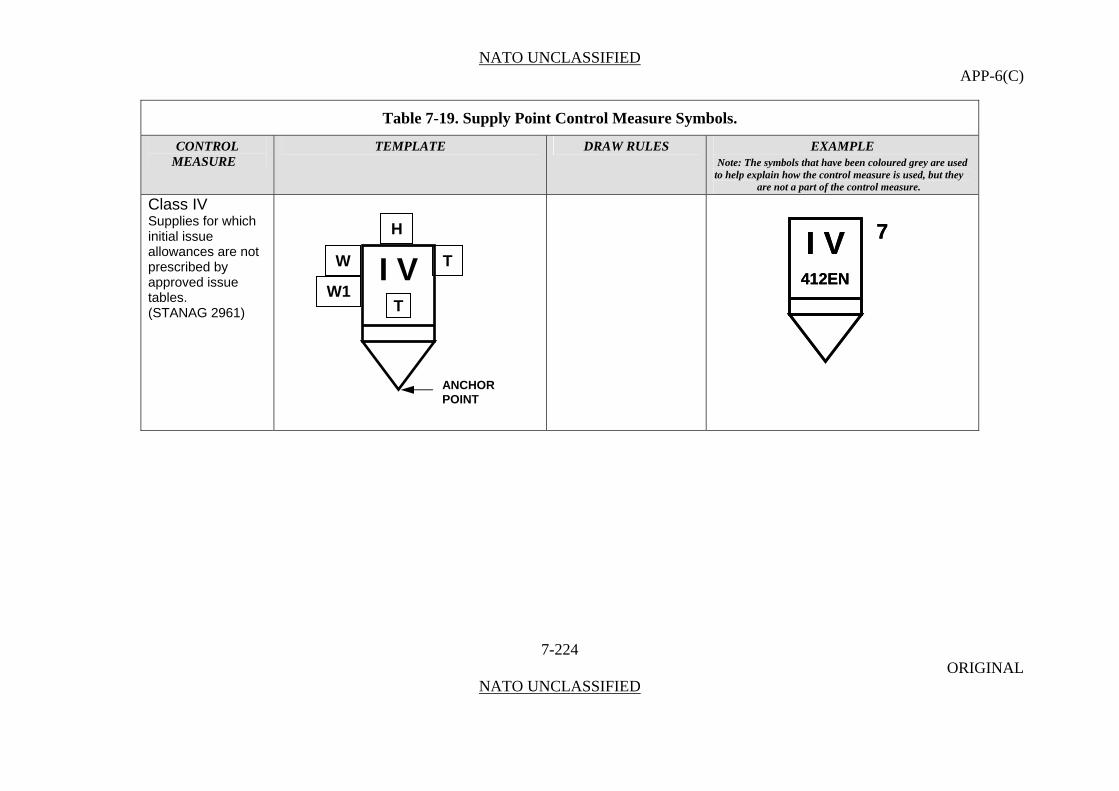
NATO UNCLASSIFIED APP-6(C)
Table 7-19. Supply Point Control Measure Symbols.
CONTROL TEMPLATE DRAW RULES EXAMPLE MEASURE Note: The symbols that have been coloured grey are used
to help explain how the control measure is used, but they are not a part of the control measure.
Class IV
7-224 ORIGINAL
NATO UNCLASSIFIED
Supplies for which initial issue allowances are not prescribed by approved issue tables. (STANAG 2961)
I V 7
412EN
I V 7
412EN
I V
H
W T
W1T
ANCHORPOINT
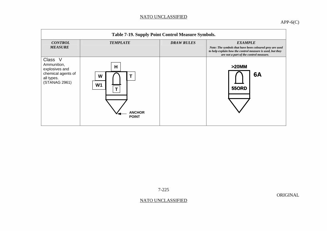
NATO UNCLASSIFIED APP-6(C)
Table 7-19. Supply Point Control Measure Symbols.
CONTROL TEMPLATE DRAW RULES EXAMPLE MEASURE Note: The symbols that have been coloured grey are used
to help explain how the control measure is used, but they are not a part of the control measure.
Class V
Ammunition, explosives and chemical agents of
>20MM
6A
55ORD
>20MM
6A
55ORD55ORD
7-225 ORIGINAL
NATO UNCLASSIFIED
all types. (STANAG 2961)
H
TW
W1T
ANCHORPOINT
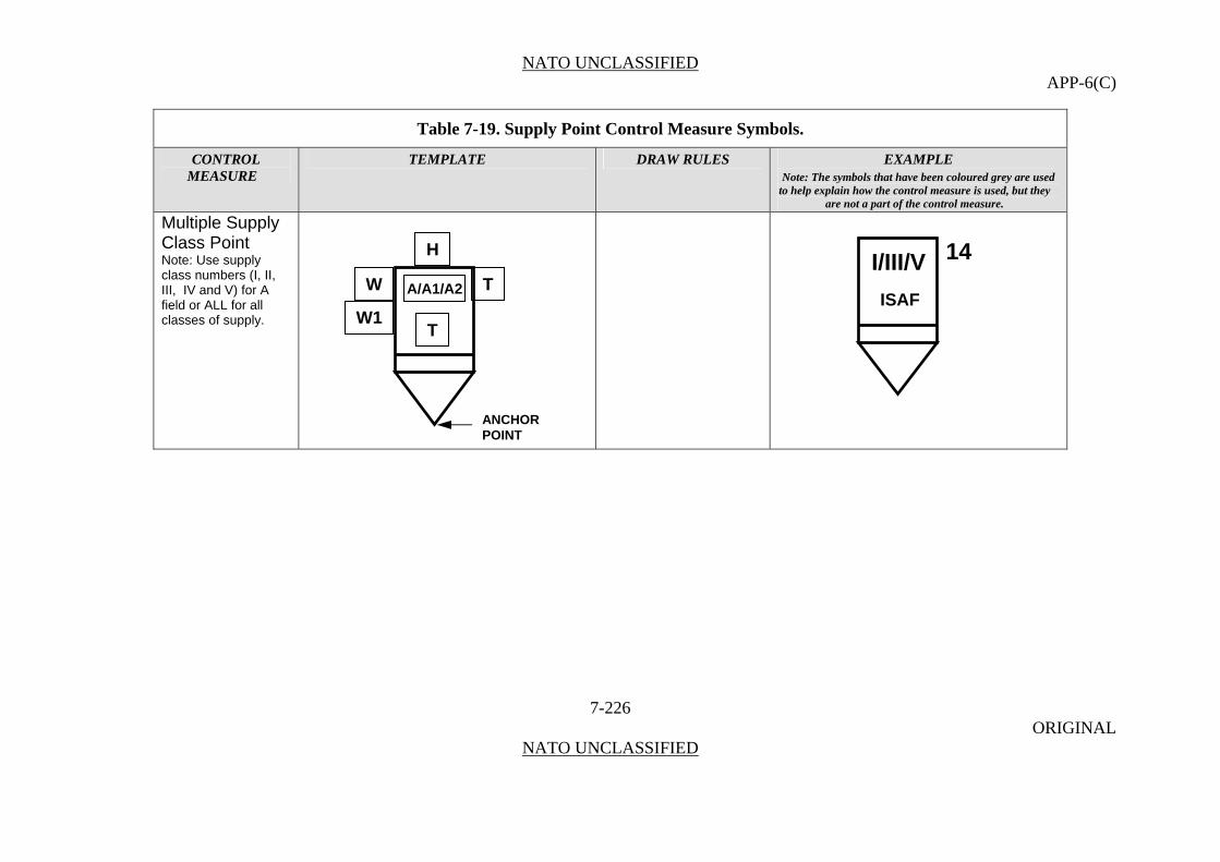
NATO UNCLASSIFIED APP-6(C)
Table 7-19. Supply Point Control Measure Symbols.
CONTROL TEMPLATE DRAW RULES EXAMPLE MEASURE Note: The symbols that have been coloured grey are used
to help explain how the control measure is used, but they are not a part of the control measure.
Multiple Supply Class Point
7-226 ORIGINAL
NATO UNCLASSIFIED
Note: Use supply class numbers (I, II, III, IV and V) for A field or ALL for all classes of supply.
H
T
TW
W1
ANCHORPOINT
A/A1/A2
14I/III/V
ISAF
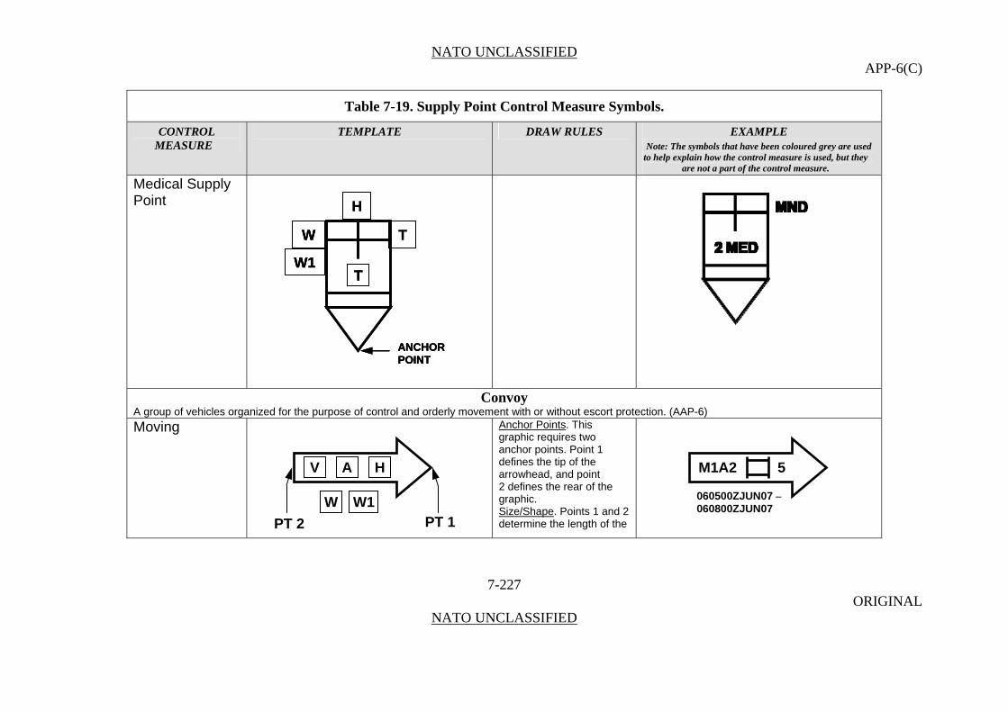
NATO UNCLASSIFIED APP-6(C)
Table 7-19. Supply Point Control Measure Symbols.
CONTROL TEMPLATE DRAW RULES EXAMPLE MEASURE Note: The symbols that have been coloured grey are used
to help explain how the control measure is used, but they are not a part of the control measure.
Medical Supply Point
H
TW
W1
ANCHORPOINT
T
H
TW
W1
W
W1
ANCHORPOINTANCHORPOINT
TT
Convoy A group of vehicles organized for the purpose of control and orderly movement with or without escort protection. (AAP-6) Moving Anchor Points. This
graphic requires two anchor points. Point 1 defines the tip of the arrowhead, and point
7-227 ORIGINAL
NATO UNCLASSIFIED
2 defines the rear of the graphic. Size/Shape. Points 1 and 2 determine the length of the
AV H
W W1PT 1 PT 2
M1A2 5
060500ZJUN07 –060800ZJUN07
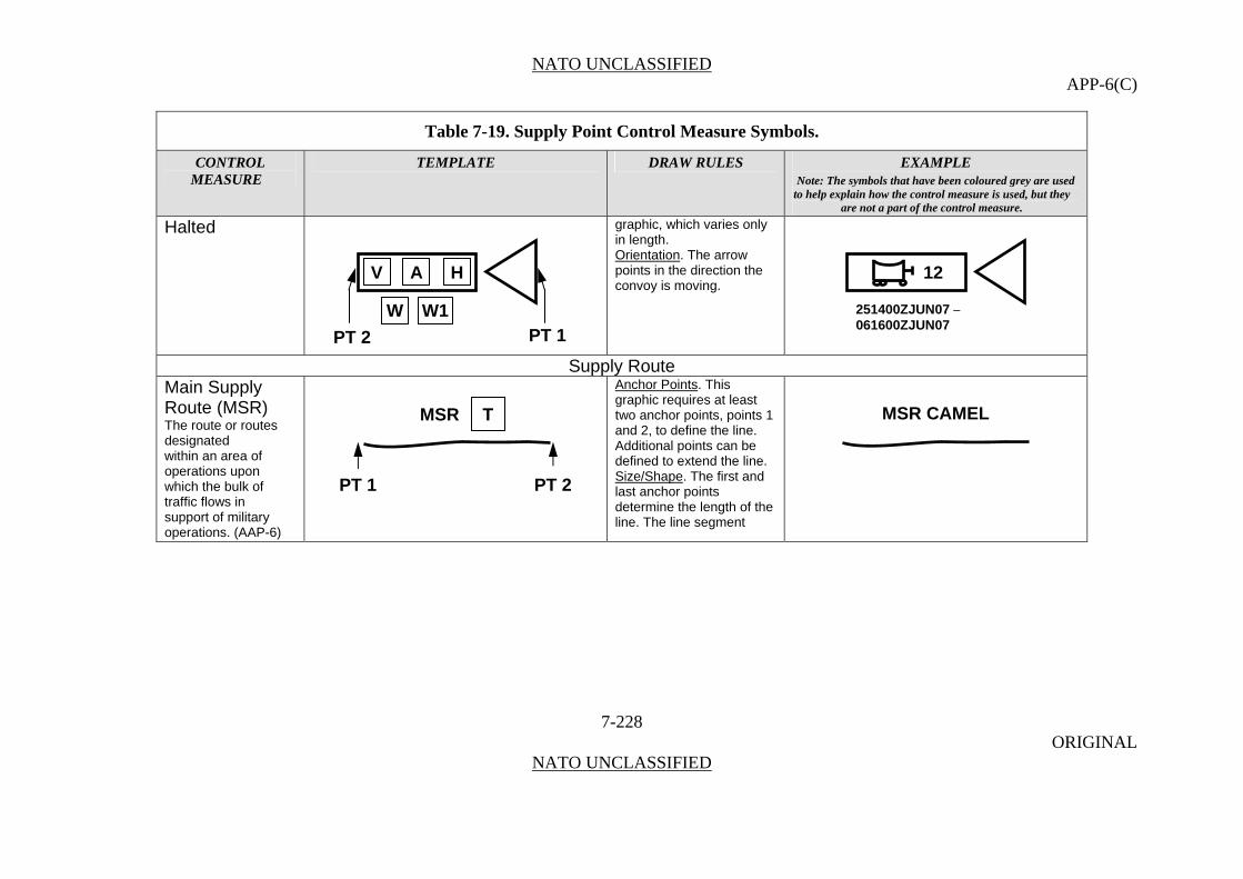
NATO UNCLASSIFIED APP-6(C)
Table 7-19. Supply Point Control Measure Symbols.
CONTROL TEMPLATE DRAW RULES EXAMPLE MEASURE Note: The symbols that have been coloured grey are used
to help explain how the control measure is used, but they are not a part of the control measure.
Halted graphic, which varies only in length. Orientation
7-228 ORIGINAL
NATO UNCLASSIFIED
. The arrow points in the direction the convoy is moving.
Supply Route Main Supply Route (MSR) The route or routes designated within an area of operations upon which the bulk of traffic flows in support of military operations. (AAP-6)
Anchor Points. This graphic requires at least two anchor points, points 1 and 2, to define the line. Additional points can be defined to extend the line. Size/Shape. The first and last anchor points determine the length of the line. The line segment
AV H
W W1PT 1 PT 2
12
251400ZJUN07 –061600ZJUN07
MSR CAMEL MSR T
PT 1 PT 2
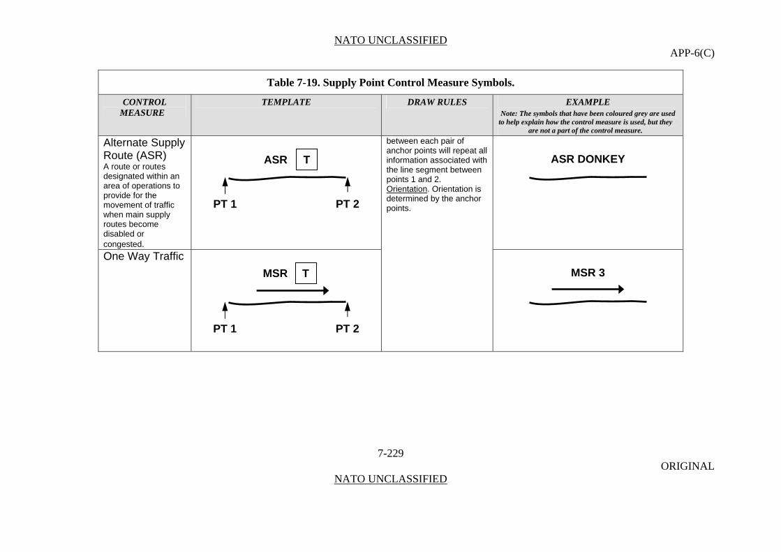
NATO UNCLASSIFIED APP-6(C)
Table 7-19. Supply Point Control Measure Symbols.
CONTROL TEMPLATE DRAW RULES EXAMPLE MEASURE Note: The symbols that have been coloured grey are used
to help explain how the control measure is used, but they are not a part of the control measure.
Alternate Supply Route (ASR)
7-229 ORIGINAL
NATO UNCLASSIFIED
A route or routes designated within an area of operations to provide for the movement of traffic when main supply routes become disabled or congested.
between each pair of anchor points will repeat all information associated with the line segment between points 1 and 2.
ASR DONKEY ASR T
One Way Traffic
Orientation. Orientation is determined by the anchor points.
PT 1 PT 2
MSR T
PT 2
MSR 3
PT 1
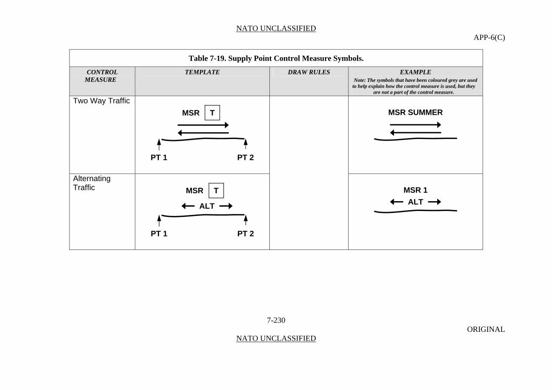
NATO UNCLASSIFIED APP-6(C)
Table 7-19. Supply Point Control Measure Symbols.
CONTROL TEMPLATE DRAW RULES EXAMPLE MEASURE Note: The symbols that have been coloured grey are used
to help explain how the control measure is used, but they are not a part of the control measure.
Two Way Traffic
7-230 ORIGINAL
NATO UNCLASSIFIED
MSR SUMMER MSR T
Alternating Traffic
PT 1 PT 2
MSR T MSR 1
ALTALT
PT 1 PT 2
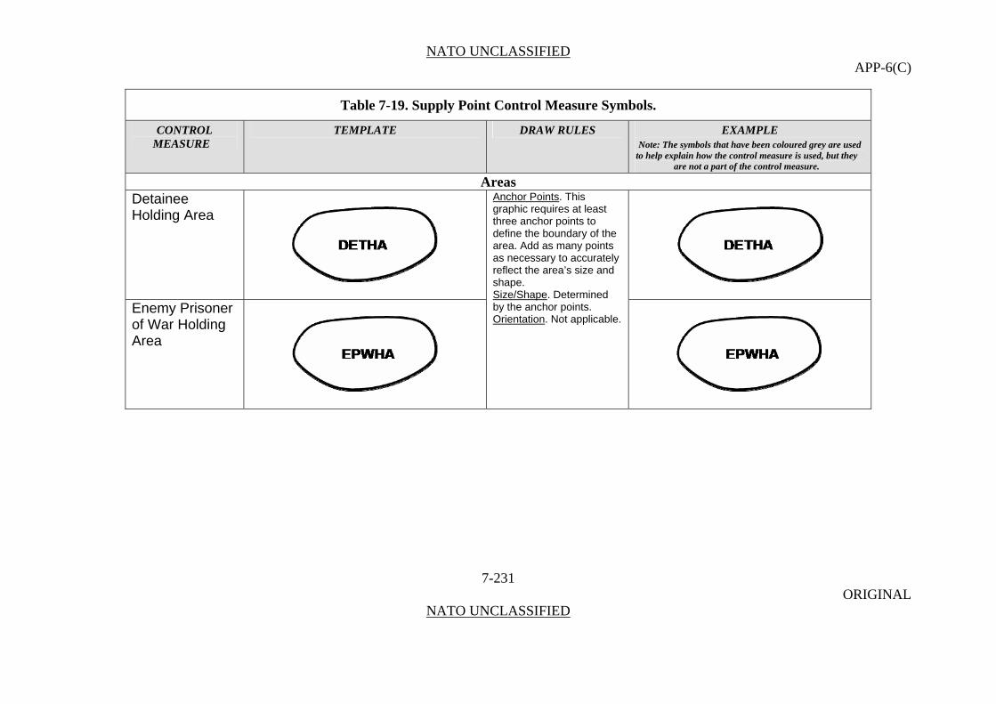
NATO UNCLASSIFIED APP-6(C)
Table 7-19. Supply Point Control Measure Symbols.
CONTROL TEMPLATE DRAW RULES EXAMPLE MEASURE Note: The symbols that have been coloured grey are used
to help explain how the control measure is used, but they are not a part of the control measure.
Areas Detainee Holding Area
7-231 ORIGINAL
NATO UNCLASSIFIED
Anchor Points. This graphic requires at least three anchor points to define the boundary of the area. Add as many points as necessary to accurately reflect the area’s size and shape. Size/Shape
Enemy Prisoner of War Holding Area
. Determined by the anchor points. Orientation. Not applicable.

NATO UNCLASSIFIED APP-6(C)
Table 7-19. Supply Point Control Measure Symbols.
CONTROL TEMPLATE DRAW RULES EXAMPLE MEASURE Note: The symbols that have been coloured grey are used
to help explain how the control measure is used, but they are not a part of the control measure.
Forward Arming and Refueling Point (FARP)
7-232 ORIGINAL
NATO UNCLASSIFIED
A temporary facility — organized, equipped, and deployed by an aviation commander, and normally located in the main battle area closer to the area where operations are being conducted than the aviation unit’s combat service area — to provide fuel and ammunition necessary for the employment of aviation maneuver units in combat. The forward arming and refueling point permits combat aircraft to rapidly refuel and rearm simultaneously.
FARP FARP

NATO UNCLASSIFIED APP-6(C)
Table 7-19. Supply Point Control Measure Symbols.
CONTROL TEMPLATE DRAW RULES EXAMPLE MEASURE Note: The symbols that have been coloured grey are used
to help explain how the control measure is used, but they are not a part of the control measure.
Refugee Holding Area
RHARHA RHARHA
Support Area Regimental Support Area
7-233 ORIGINAL
NATO UNCLASSIFIED
Anchor Points. This graphic requires at least three anchor points to define the boundary of the area. Add as many points as necessary to accurately reflect the area’s size and shape.
Brigade Support Area (BSA) A designated area in which combat service support elements from division support command and corps support command provide logistic support to a brigade.
Size/Shape. Determined by the anchor points. Orientation. Not applicable.
RSA RSA
BSA BSA

NATO UNCLASSIFIED APP-6(C)
Table 7-19. Supply Point Control Measure Symbols.
CONTROL TEMPLATE DRAW RULES EXAMPLE MEASURE Note: The symbols that have been coloured grey are used
to help explain how the control measure is used, but they are not a part of the control measure.
Division Support Area
7-234 ORIGINAL
NATO UNCLASSIFIED
An area normally located in the division rear and often positioned near air-landing facilities along the main supply route.
DSA DSA
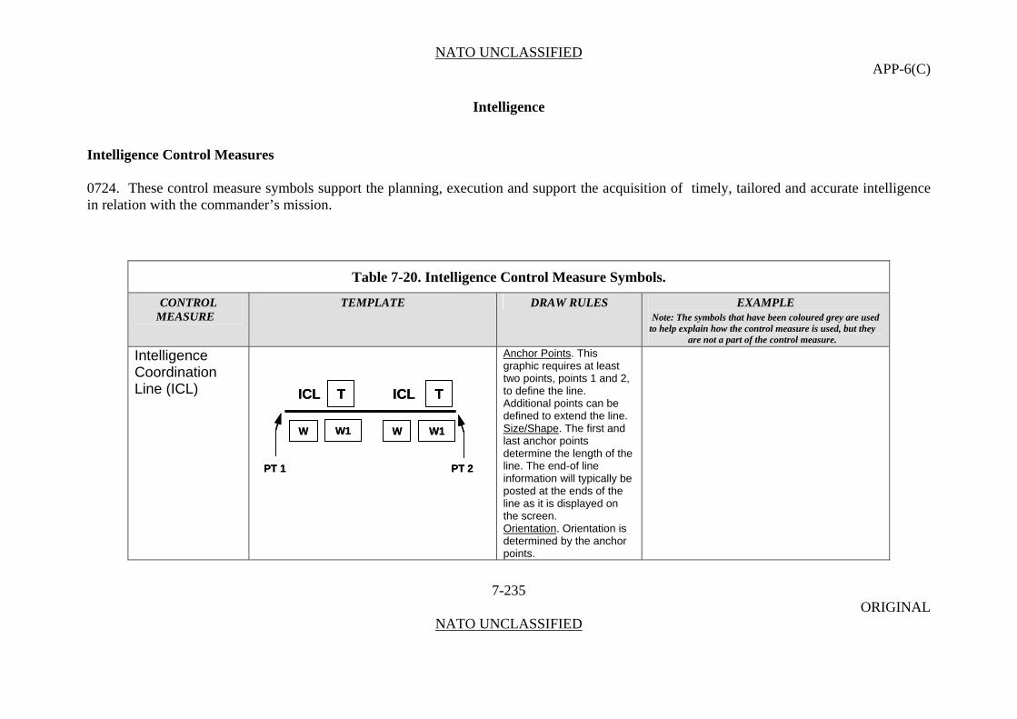
NATO UNCLASSIFIED APP-6(C)
Intelligence
Intelligence Control Measures 0724. These control measure symbols support the planning, execution and support the acquisition of timely, tailored and accurate intelligence in relation with the commander’s mission.
Table 7-20. Intelligence Control Measure Symbols.
CONTROL TEMPLATE DRAW RULES EXAMPLE MEASURE Note: The symbols that have been coloured grey are used
to help explain how the control measure is used, but they are not a part of the control measure.
Intelligence Coordination Line (ICL)
Anchor Points. This graphic requires at least two points, points 1 and 2, to define the line. Additional points can be defined to extend the line.
ICL TICL T
W W1 W W1
PT 2PT 1
ICL TICL T
W W1 W W1
PT 2PT 1
Size/Shape. The first and last anchor points determine the length of the line. The end-of line information will typically be posted at the ends of the line as it is displayed on the screen. Orientation. Orientation is determined by the anchor points.
7-235 ORIGINAL
NATO UNCLASSIFIED
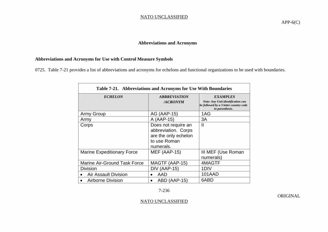
NATO UNCLASSIFIED APP-6(C)
7-236 ORIGINAL
NATO UNCLASSIFIED
Abbreviations and Acronyms Abbreviations and Acronyms for Use with Control Measure Symbols 0725. Table 7-21 provides a list of abbreviations and acronyms for echelons and functional organizations to be used with boundaries.
Table 7-21. Abbreviations and Acronyms for Use With Boundaries
ECHELON ABBREVIATION /ACRONYM
EXAMPLES Note: Any Unit identification can
be followed by a 3 letter country code in parenthesis.
Army Group AG (AAP-15) 1AG Army A (AAP-15) 3A Corps Does not require an
abbreviation. Corps are the only echelon to use Roman numerals.
II
Marine Expeditionary Force MEF (AAP-15) III MEF (Use Roman numerals)
Marine Air-Ground Task Force MAGTF (AAP-15) 4MAGTF Division DIV (AAP-15) 1DIV Air Assault Division AAD 101AAD Airborne Division ABD (AAP-15) 6ABD
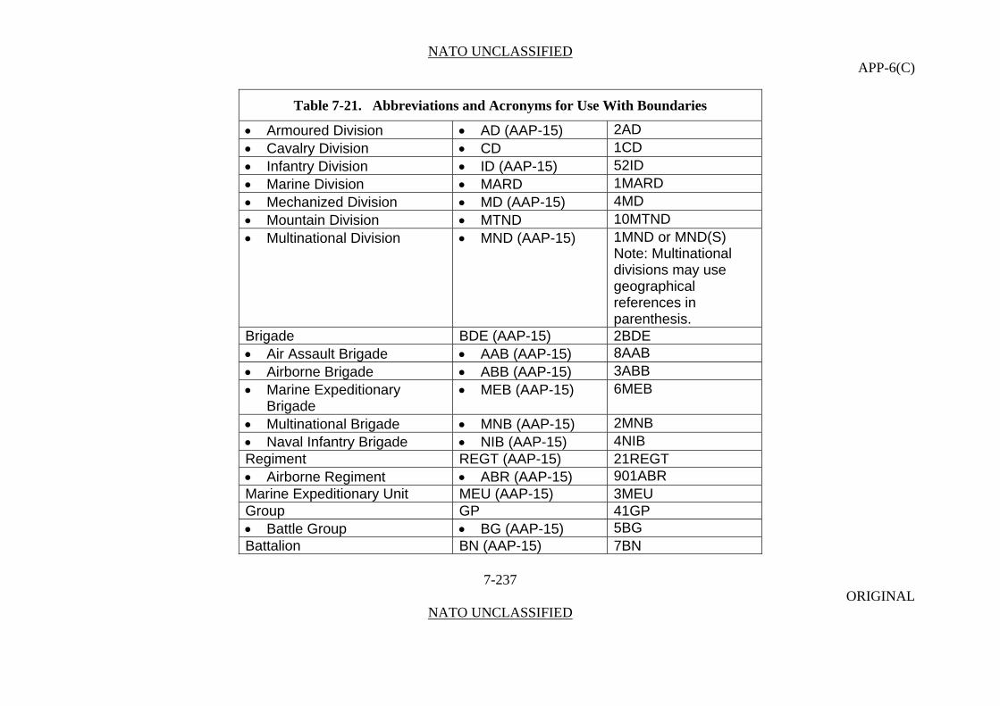
NATO UNCLASSIFIED APP-6(C)
7-237 ORIGINAL
NATO UNCLASSIFIED
Table 7-21. Abbreviations and Acronyms for Use With Boundaries
Armoured Division AD (AAP-15) 2AD Cavalry Division CD 1CD Infantry Division ID (AAP-15) 52ID Marine Division MARD 1MARD Mechanized Division MD (AAP-15) 4MD Mountain Division MTND 10MTND Multinational Division MND (AAP-15) 1MND or MND(S)
Note: Multinational divisions may use geographical references in parenthesis.
Brigade BDE (AAP-15) 2BDE Air Assault Brigade AAB (AAP-15) 8AAB Airborne Brigade ABB (AAP-15) 3ABB Marine Expeditionary
Brigade MEB (AAP-15) 6MEB
Multinational Brigade MNB (AAP-15) 2MNB Naval Infantry Brigade NIB (AAP-15) 4NIB Regiment REGT (AAP-15) 21REGT Airborne Regiment ABR (AAP-15) 901ABR Marine Expeditionary Unit MEU (AAP-15) 3MEU Group GP 41GP Battle Group BG (AAP-15) 5BG Battalion BN (AAP-15) 7BN
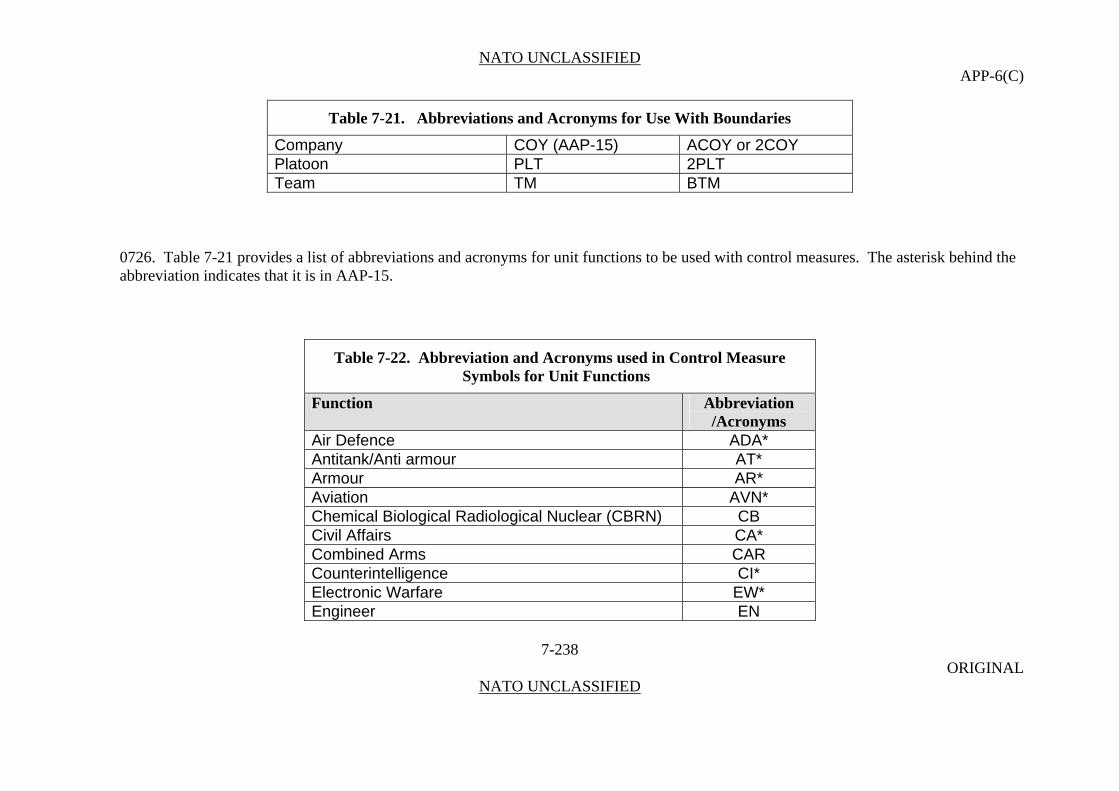
NATO UNCLASSIFIED APP-6(C)
7-238 ORIGINAL
NATO UNCLASSIFIED
Table 7-21. Abbreviations and Acronyms for Use With Boundaries
Company COY (AAP-15) ACOY or 2COY Platoon PLT 2PLT Team TM BTM
0726. Table 7-21 provides a list of abbreviations and acronyms for unit functions to be used with control measures. The asterisk behind the abbreviation indicates that it is in AAP-15.
Table 7-22. Abbreviation and Acronyms used in Control Measure Symbols for Unit Functions
Function Abbreviation /Acronyms
Air Defence ADA* Antitank/Anti armour AT* Armour AR* Aviation AVN* Chemical Biological Radiological Nuclear (CBRN) CB Civil Affairs CA* Combined Arms CAR Counterintelligence CI* Electronic Warfare EW* Engineer EN

NATO UNCLASSIFIED APP-6(C)
7-239 ORIGINAL
NATO UNCLASSIFIED
Table 7-22. Abbreviation and Acronyms used in Control Measure Symbols for Unit Functions
Function Abbreviation /Acronyms
Explosive Ordnance Disposal EOD* Field Artillery FA* Infantry IN Logistics LOG* Maintenance MNT Medical MED* Military Intelligence MI* Military Police MP* Naval NAV Ordnance ORD Quartermaster QM Reconnaissance REC Signal SIG Special Forces/ SF Special Operations Force SOF Surveillance SUR Sustainment SUST Transportation TPT

NATO UNCLASSIFIED APP-6(C)
7-240 ORIGINAL
NATO UNCLASSIFIED
(INTENTIONALLY BLANK)
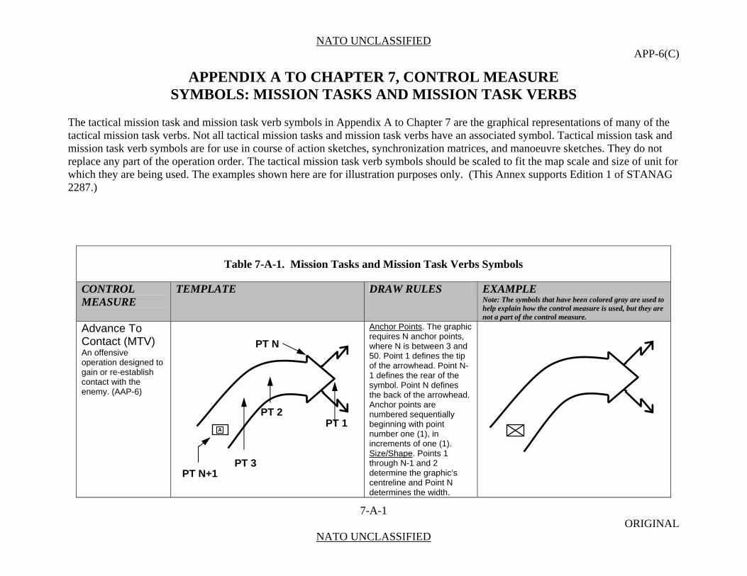
NATO UNCLASSIFIED APP-6(C)
7-A-1 ORIGINAL
NATO UNCLASSIFIED
APPENDIX A TO CHAPTER 7, CONTROL MEASURE SYMBOLS: MISSION TASKS AND MISSION TASK VERBS
The tactical mission task and mission task verb symbols in Appendix A to Chapter 7 are the graphical representations of many of the tactical mission task verbs. Not all tactical mission tasks and mission task verbs have an associated symbol. Tactical mission task and mission task verb symbols are for use in course of action sketches, synchronization matrices, and manoeuvre sketches. They do not replace any part of the operation order. The tactical mission task verb symbols should be scaled to fit the map scale and size of unit for which they are being used. The examples shown here are for illustration purposes only. (This Annex supports Edition 1 of STANAG 2287.)
Table 7-A-1. Mission Tasks and Mission Task Verbs Symbols
CONTROL MEASURE
TEMPLATE DRAW RULES EXAMPLE Note: The symbols that have been colored gray are used to help explain how the control measure is used, but they are not a part of the control measure.
Advance To Contact (MTV) An offensive operation designed to gain or re-establish contact with the enemy. (AAP-6)
Anchor Points. The graphic requires N anchor points, where N is between 3 and 50. Point 1 defines the tip of the arrowhead. Point N-1 defines the rear of the symbol. Point N defines the back of the arrowhead. Anchor points are numbered sequentially beginning with point number one (1), in increments of one (1). Size/Shape. Points 1 through N-1 and 2 determine the graphic’s centreline and Point N determines the width.
PT 1 A
PT 2
PT N+1 PT 3
PT N
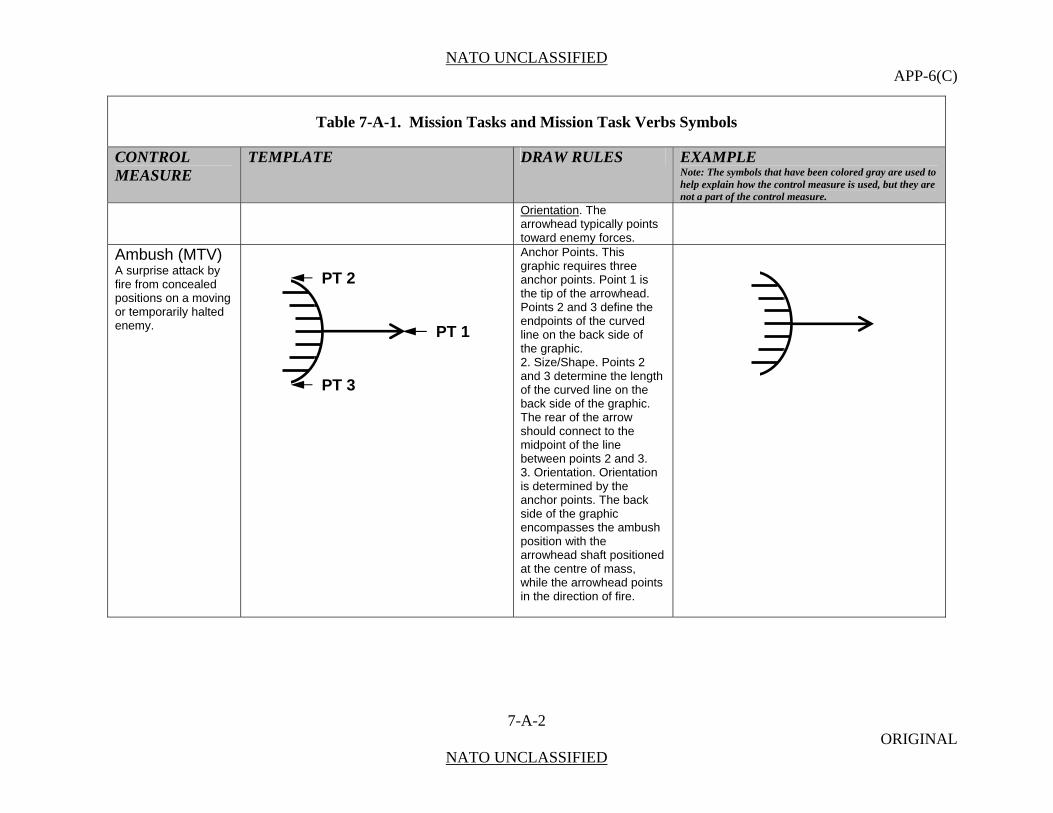
NATO UNCLASSIFIED APP-6(C)
7-A-2 ORIGINAL
NATO UNCLASSIFIED
Table 7-A-1. Mission Tasks and Mission Task Verbs Symbols
CONTROL MEASURE
TEMPLATE DRAW RULES EXAMPLE Note: The symbols that have been colored gray are used to help explain how the control measure is used, but they are not a part of the control measure.
Orientation. The arrowhead typically points toward enemy forces.
Ambush (MTV) A surprise attack by fire from concealed positions on a moving or temporarily halted enemy.
Anchor Points. This graphic requires three anchor points. Point 1 is the tip of the arrowhead. Points 2 and 3 define the endpoints of the curved line on the back side of the graphic. 2. Size/Shape. Points 2 and 3 determine the length of the curved line on the back side of the graphic. The rear of the arrow should connect to the midpoint of the line between points 2 and 3. 3. Orientation. Orientation is determined by the anchor points. The back side of the graphic encompasses the ambush position with the arrowhead shaft positioned at the centre of mass, while the arrowhead points in the direction of fire.
PT 2
PT 1
PT 3
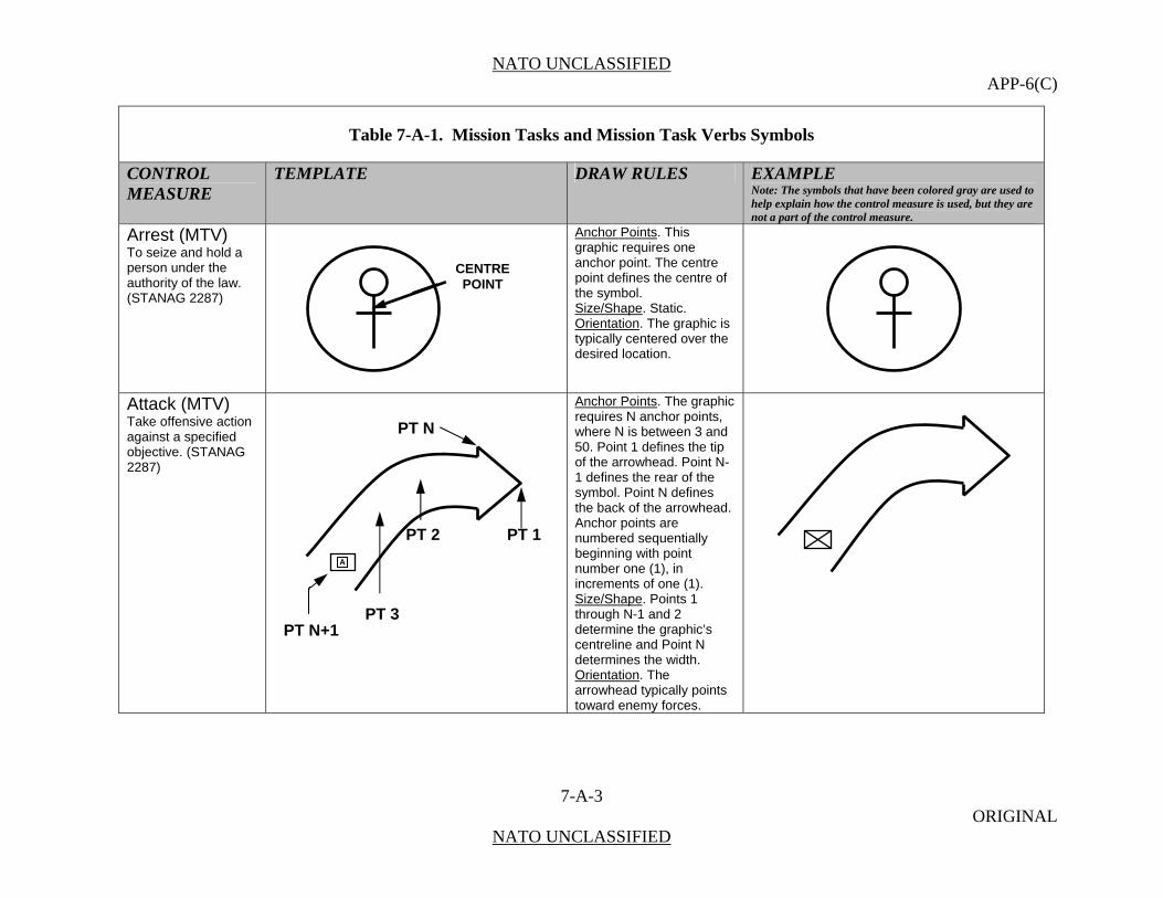
NATO UNCLASSIFIED APP-6(C)
7-A-3 ORIGINAL
NATO UNCLASSIFIED
Table 7-A-1. Mission Tasks and Mission Task Verbs Symbols
CONTROL MEASURE
TEMPLATE DRAW RULES EXAMPLE Note: The symbols that have been colored gray are used to help explain how the control measure is used, but they are not a part of the control measure.
Arrest (MTV) To seize and hold a person under the authority of the law. (STANAG 2287)
Anchor Points. This graphic requires one anchor point. The centre point defines the centre of the symbol. Size/Shape. Static. Orientation. The graphic is typically centered over the desired location.
Attack (MTV) Take offensive action against a specified objective. (STANAG 2287)
Anchor Points. The graphic requires N anchor points, where N is between 3 and 50. Point 1 defines the tip of the arrowhead. Point N-1 defines the rear of the symbol. Point N defines the back of the arrowhead. Anchor points are numbered sequentially beginning with point number one (1), in increments of one (1). Size/Shape. Points 1 through N-1 and 2 determine the graphic’s centreline and Point N determines the width. Orientation. The arrowhead typically points toward enemy forces.
CENTREPOINT
PT 1 A
PT 2
PT N+1 PT 3
PT N
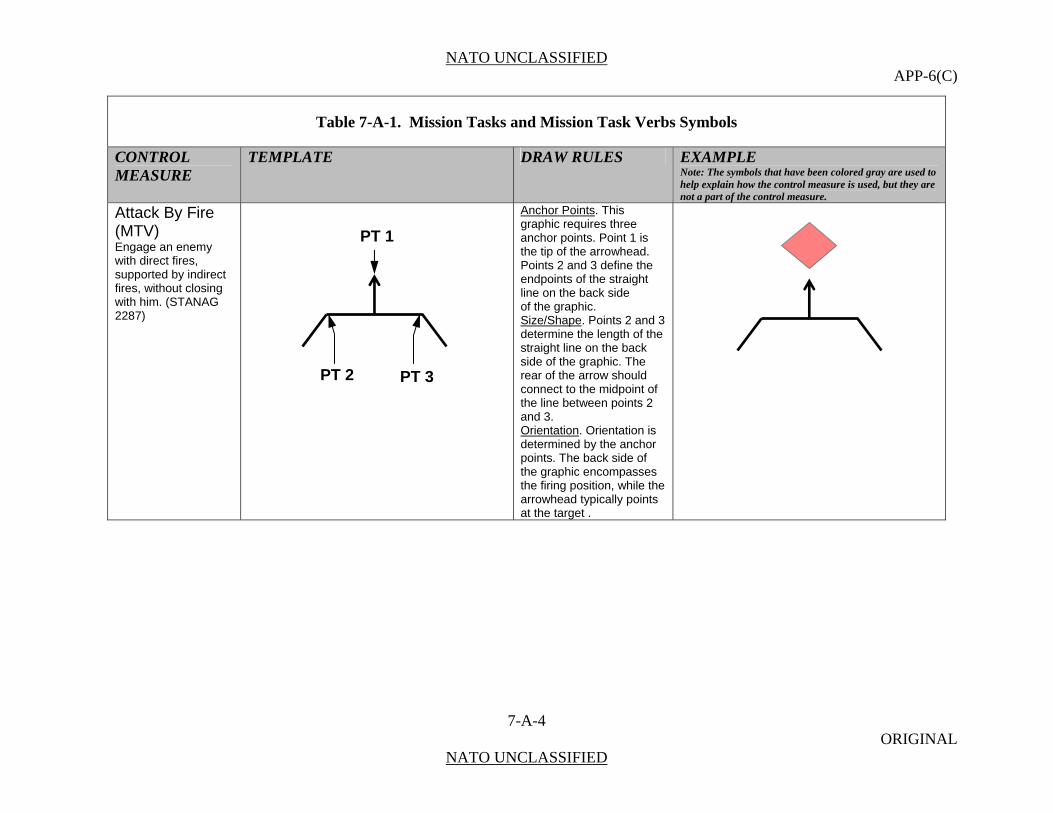
NATO UNCLASSIFIED APP-6(C)
7-A-4 ORIGINAL
NATO UNCLASSIFIED
Table 7-A-1. Mission Tasks and Mission Task Verbs Symbols
CONTROL MEASURE
TEMPLATE DRAW RULES EXAMPLE Note: The symbols that have been colored gray are used to help explain how the control measure is used, but they are not a part of the control measure.
Attack By Fire (MTV) Engage an enemy with direct fires, supported by indirect fires, without closing with him. (STANAG 2287)
Anchor Points. This graphic requires three anchor points. Point 1 is the tip of the arrowhead. Points 2 and 3 define the endpoints of the straight line on the back side of the graphic. Size/Shape. Points 2 and 3 determine the length of the straight line on the back side of the graphic. The rear of the arrow should connect to the midpoint of the line between points 2 and 3. Orientation. Orientation is determined by the anchor points. The back side of the graphic encompasses the firing position, while the arrowhead typically points at the target .
PT 1
PT 2 PT 3

NATO UNCLASSIFIED APP-6(C)
7-A-5 ORIGINAL
NATO UNCLASSIFIED
Table 7-A-1. Mission Tasks and Mission Task Verbs Symbols
CONTROL MEASURE
TEMPLATE DRAW RULES EXAMPLE Note: The symbols that have been colored gray are used to help explain how the control measure is used, but they are not a part of the control measure.
Block (MT/MTV) Deny enemy access to a given area, or to prevent his advance in a particular direction. (STANAG 2287)
Anchor Points. This graphic requires three anchor points. Points 1 and 2 define the endpoints of the graphic’s vertical line. Point 3 defines the the endpoint of the graphic’s horizontal line. Size/Shape. Points 1 and 2 determine the length of the vertical line. Points 2 and 3 determine the length of the horizontal line, which will project perpendicularly from the midpoint of the vertical line. Orientation. The head of the “T” faces enemy forces.
BPT 3
PT 1
PT 2
B

NATO UNCLASSIFIED APP-6(C)
7-A-6 ORIGINAL
NATO UNCLASSIFIED
Table 7-A-1. Mission Tasks and Mission Task Verbs Symbols
CONTROL MEASURE
TEMPLATE DRAW RULES EXAMPLE Note: The symbols that have been colored gray are used to help explain how the control measure is used, but they are not a part of the control measure.
Breach (MT/MTV) Break through or secure passage through an enemy defence, obstacle, or fortification. (STANAG 2287)
Anchor Points. This graphic requires three anchor points. Points 1 and 2 define the endpoints of the graphic’s opening and point 3 defines the rear of the graphic. Size/Shape. Points 1 and 2 determine the graphic’s height and point 3 determines its length. The vertical line at the rear of the graphic will be the same height as the opening. Orientation. The opening defines the span of the breach and faces enemy forces.
PT 2
PT 1
B PT 3
B

NATO UNCLASSIFIED APP-6(C)
7-A-7 ORIGINAL
NATO UNCLASSIFIED
Table 7-A-1. Mission Tasks and Mission Task Verbs Symbols
CONTROL MEASURE
TEMPLATE DRAW RULES EXAMPLE Note: The symbols that have been colored gray are used to help explain how the control measure is used, but they are not a part of the control measure.
Bypass (MT/MTV) Manoeuvre around an obstacle, position, or enemy force to maintain the momentum of advance. (STANAG 2287)
Anchor Points. This graphic requires three anchor points. Points 1 and 2 define the endpoints of the graphic’s opening and point 3 defines the rear of the graphic. Size/Shape. Points 1 and 2 determine the graphic’s height and point 3 determines its length. The vertical line at the rear of the graphic will be the same height as the opening. Orientation. The opening defines the span of the bypass and faces enemy forces.
B
B
PT 2
PT 1
PT 3

NATO UNCLASSIFIED APP-6(C)
7-A-8 ORIGINAL
NATO UNCLASSIFIED
Table 7-A-1. Mission Tasks and Mission Task Verbs Symbols
CONTROL MEASURE
TEMPLATE DRAW RULES EXAMPLE Note: The symbols that have been colored gray are used to help explain how the control measure is used, but they are not a part of the control measure.
Canalize (MT/MTV) Restrict enemy movement to a narrow zone. (STANAG 2287)
Anchor Points. This graphic requires three anchor points. Points 1 and 2 define the endpoints of the graphic’s opening and point 3 defines the rear of the graphic. Size/Shape. Points 1 and 2 determine the graphic’s height and point 3 determines its length. The vertical line at the rear of the graphic will be the same height as the opening. Orientation. The opening defines the span of the canalization and faces enemy forces.
CC
PT 2
PT 1
PT 3
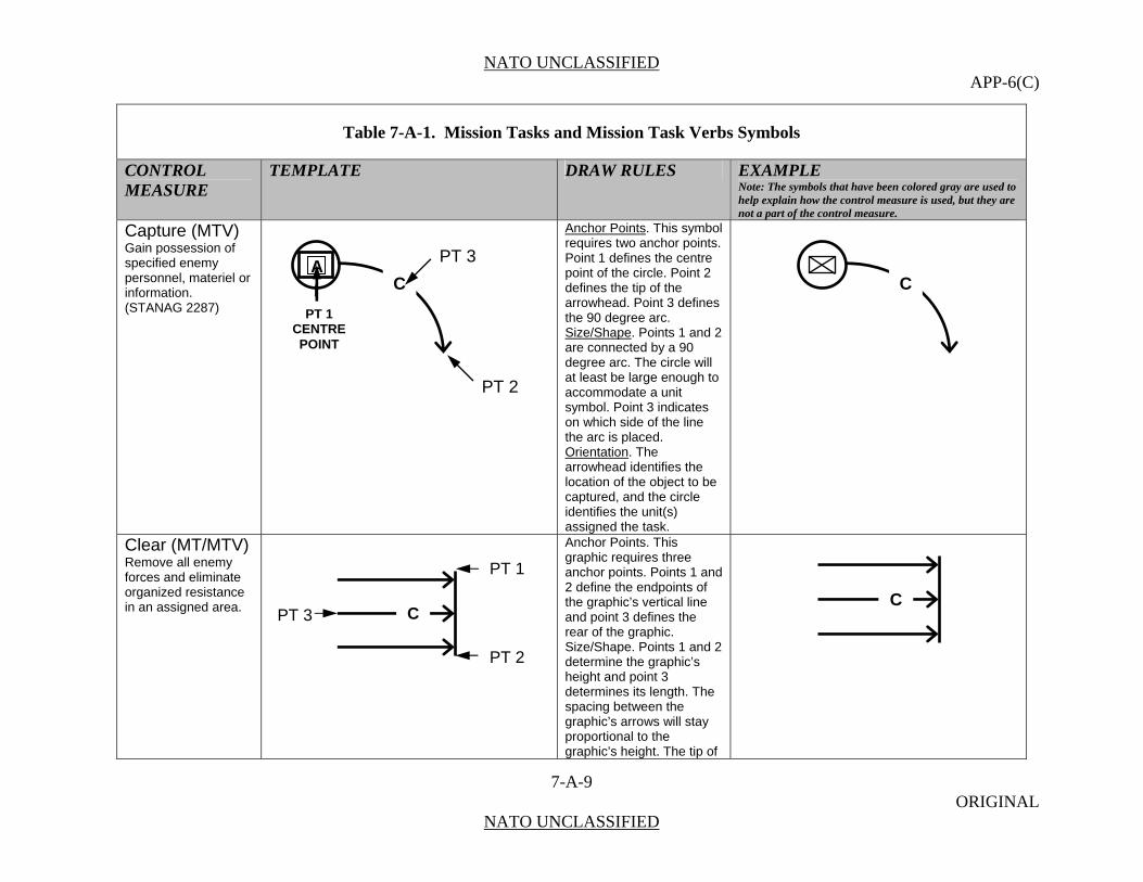
NATO UNCLASSIFIED APP-6(C)
7-A-9 ORIGINAL
NATO UNCLASSIFIED
Table 7-A-1. Mission Tasks and Mission Task Verbs Symbols
CONTROL MEASURE
TEMPLATE DRAW RULES EXAMPLE Note: The symbols that have been colored gray are used to help explain how the control measure is used, but they are not a part of the control measure.
Capture (MTV) Gain possession of specified enemy personnel, materiel or information. (STANAG 2287)
Anchor Points. This symbol requires two anchor points. Point 1 defines the centre point of the circle. Point 2 defines the tip of the arrowhead. Point 3 defines the 90 degree arc. Size/Shape. Points 1 and 2 are connected by a 90 degree arc. The circle will at least be large enough to accommodate a unit symbol. Point 3 indicates on which side of the line the arc is placed. Orientation. The arrowhead identifies the location of the object to be captured, and the circle identifies the unit(s) assigned the task.
Clear (MT/MTV) Remove all enemy forces and eliminate organized resistance in an assigned area.
Anchor Points. This graphic requires three anchor points. Points 1 and 2 define the endpoints of the graphic’s vertical line and point 3 defines the rear of the graphic. Size/Shape. Points 1 and 2 determine the graphic’s height and point 3 determines its length. The spacing between the graphic’s arrows will stay proportional to the graphic’s height. The tip of
C
CPT 3
PT 1
PT 2
C
A
PT 2
C
PT 1 CENTRE POINT
PT 3
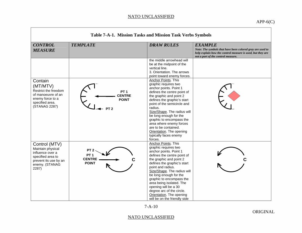
NATO UNCLASSIFIED APP-6(C)
7-A-10 ORIGINAL
NATO UNCLASSIFIED
Table 7-A-1. Mission Tasks and Mission Task Verbs Symbols
CONTROL MEASURE
TEMPLATE DRAW RULES EXAMPLE Note: The symbols that have been colored gray are used to help explain how the control measure is used, but they are not a part of the control measure.
the middle arrowhead will be at the midpoint of the vertical line. 3. Orientation. The arrows point toward enemy forces.
Contain (MT/MTV) Restrict the freedom of manoeuvre of an enemy force to a specified area. (STANAG 2287)
Anchor Points. This graphic requires two anchor points. Point 1 defines the centre point of the graphic and point 2 defines the graphic’s start point of the semicircle and radius. Size/Shape. The radius will be long enough for the graphic to encompass the area where enemy forces are to be contained. Orientation. The opening typically faces enemy forces.
Control (MTV) Maintain physical influence over a specified area to prevent its use by an enemy. (STANAG 2287)
Anchor Points. This graphic requires two anchor points. Point 1 defines the centre point of the graphic and point 2 defines the graphic’s start point and radius. Size/Shape. The radius will be long enough for the graphic to encompass the area being isolated. The opening will be a 30 degree arc of the circle. Orientation. The opening will be on the friendly side
CPT 1
CENTRE POINT
C
PT 2
PT 2
PT 1CENTRE POINT
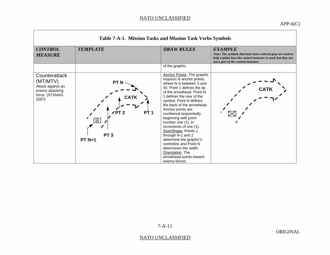
NATO UNCLASSIFIED APP-6(C)
7-A-11 ORIGINAL
NATO UNCLASSIFIED
Table 7-A-1. Mission Tasks and Mission Task Verbs Symbols
CONTROL MEASURE
TEMPLATE DRAW RULES EXAMPLE Note: The symbols that have been colored gray are used to help explain how the control measure is used, but they are not a part of the control measure.
of the graphic.
Counterattack (MT/MTV) Attack against an enemy attacking force. (STANAG 2287)
Anchor Points. The graphic requires N anchor points, where N is between 3 and 50. Point 1 defines the tip of the arrowhead. Point N-1 defines the rear of the symbol. Point N defines the back of the arrowhead. Anchor points are numbered sequentially beginning with point number one (1), in increments of one (1). Size/Shape. Points 1 through N-1 and 2 determine the graphic’s centreline and Point N determines the width. Orientation. The arrowhead points toward enemy forces.
PT 1 A
PT 2
PT N+1 PT 3
PT N
CATK
CATK

NATO UNCLASSIFIED APP-6(C)
7-A-12 ORIGINAL
NATO UNCLASSIFIED
Table 7-A-1. Mission Tasks and Mission Task Verbs Symbols
CONTROL MEASURE
TEMPLATE DRAW RULES EXAMPLE Note: The symbols that have been colored gray are used to help explain how the control measure is used, but they are not a part of the control measure.
Counterattack By Fire (MT) Attack against an enemy attacking force using fires. NOTE: This is a method of counterattack.
Anchor Points. The graphic requires N anchor points, where N is between 3 and 50. Point 1 defines the tip of the arrowhead of the fire portion of the symbol. Point N-1 defines the rear of the symbol. Point N defines the back of the arrowhead. Anchor points are numbered sequentially beginning with point number one (1), in increments of one (1). Size/Shape. Points 1 through N-1 and 2 determine the graphic’s centreline and Point N determines the width. Orientation. The arrowhead points toward enemy forces.
CATK
PT 1 PT 2
PT N+1 PT 3
PT N
CATK
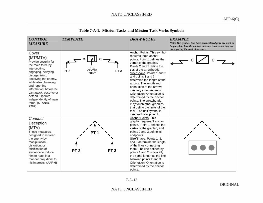
NATO UNCLASSIFIED APP-6(C)
7-A-13 ORIGINAL
NATO UNCLASSIFIED
Table 7-A-1. Mission Tasks and Mission Task Verbs Symbols
CONTROL MEASURE
TEMPLATE DRAW RULES EXAMPLE Note: The symbols that have been colored gray are used to help explain how the control measure is used, but they are not a part of the control measure.
Cover (MT/MTV) Provide security for the main force by intercepting, engaging, delaying, disorganizing, deceiving the enemy, while also observing and reporting information, before he can attack, observe or defend. Operate independently of main force. (STANAG 2287)
Anchor Points. This symbol requires three anchor points. Point 1 defines the vertex of the graphic. Points 2 and 3 define the tips of the arrowheads. Size/Shape. Points 1 and 2 and points 1 and 3 determine the length of the arrows. The length and orientation of the arrows can vary independently. Orientation. Orientation is determined by the anchor points. The arrowheads may touch other graphics that define the limits of the task. The unit symbol is centreed over point 1.
Conduct Deception (MTV) Those measures designed to mislead the enemy by manipulation, distortion, or falsification of evidence to induce him to react in a manner prejudicial to his interests. (AAP-6)
Anchor Points. This graphic requires 3 anchor points. Point 1 defines the vertex of the graphic, and points 2 and 3 define its endpoints. Size/Shape. Points 1, 2, and 3 determine the length of the lines connecting them. The line defined by points 1 and 2 is typically the same length as the line between points 2 and 3. Orientation. Orientation is determined by the anchor points.
C CA
PT 1 CENTRE POINT
PT 2 PT 3
C C
PT 2
PT 1
PT 3
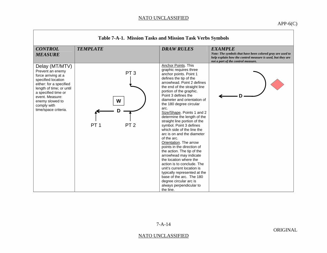
NATO UNCLASSIFIED APP-6(C)
7-A-14 ORIGINAL
NATO UNCLASSIFIED
Table 7-A-1. Mission Tasks and Mission Task Verbs Symbols
CONTROL MEASURE
TEMPLATE DRAW RULES EXAMPLE Note: The symbols that have been colored gray are used to help explain how the control measure is used, but they are not a part of the control measure.
Delay (MT/MTV) Prevent an enemy force arriving at a specified location either: for a specified length of time; or until a specified time or event. Measure: enemy slowed to comply with time/space criteria.
Anchor Points. This graphic requires three anchor points. Point 1 defines the tip of the arrowhead. Point 2 defines the end of the straight line portion of the graphic. Point 3 defines the diameter and orientation of the 180 degree circular arc. Size/Shape. Points 1 and 2 determine the length of the straight line portion of the symbol. Point 3 defines which side of the line the arc is on and the diameter of the arc. Orientation. The arrow points in the direction of the action. The tip of the arrowhead may indicate the location where the action is to conclude. The unit’s current location is typically represented at the base of the arc. The 180 degree circular arc is always perpendicular to the line.
PT 1
D
W
PT 3
PT 2
D
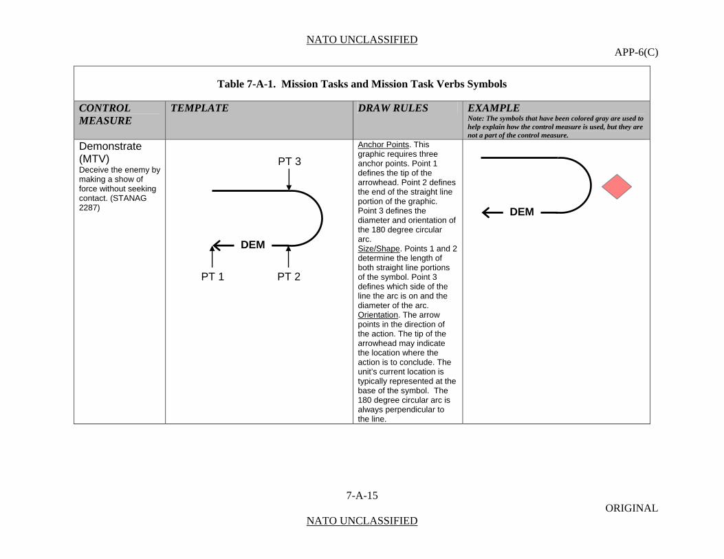
NATO UNCLASSIFIED APP-6(C)
7-A-15 ORIGINAL
NATO UNCLASSIFIED
Table 7-A-1. Mission Tasks and Mission Task Verbs Symbols
CONTROL MEASURE
TEMPLATE DRAW RULES EXAMPLE Note: The symbols that have been colored gray are used to help explain how the control measure is used, but they are not a part of the control measure.
Demonstrate (MTV) Deceive the enemy by making a show of force without seeking contact. (STANAG 2287)
Anchor Points. This graphic requires three anchor points. Point 1 defines the tip of the arrowhead. Point 2 defines the end of the straight line portion of the graphic. Point 3 defines the diameter and orientation of the 180 degree circular arc. Size/Shape. Points 1 and 2 determine the length of both straight line portions of the symbol. Point 3 defines which side of the line the arc is on and the diameter of the arc. Orientation. The arrow points in the direction of the action. The tip of the arrowhead may indicate the location where the action is to conclude. The unit’s current location is typically represented at the base of the symbol. The 180 degree circular arc is always perpendicular to the line.
PT 1
DEM
PT 3
PT 2
DEM
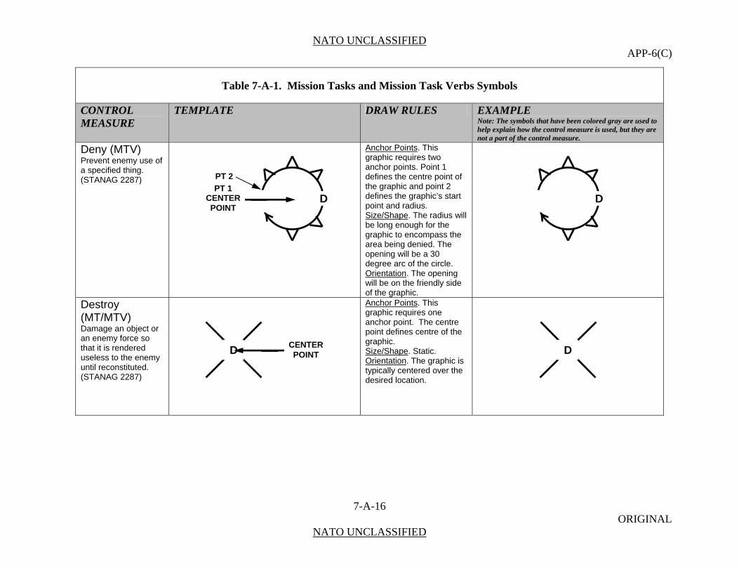
NATO UNCLASSIFIED APP-6(C)
7-A-16 ORIGINAL
NATO UNCLASSIFIED
Table 7-A-1. Mission Tasks and Mission Task Verbs Symbols
CONTROL MEASURE
TEMPLATE DRAW RULES EXAMPLE Note: The symbols that have been colored gray are used to help explain how the control measure is used, but they are not a part of the control measure.
Deny (MTV) Prevent enemy use of a specified thing. (STANAG 2287)
Anchor Points. This graphic requires two anchor points. Point 1 defines the centre point of the graphic and point 2 defines the graphic’s start point and radius. Size/Shape. The radius will be long enough for the graphic to encompass the area being denied. The opening will be a 30 degree arc of the circle. Orientation. The opening will be on the friendly side of the graphic.
Destroy (MT/MTV) Damage an object or an enemy force so that it is rendered useless to the enemy until reconstituted. (STANAG 2287)
Anchor Points. This graphic requires one anchor point. The centre point defines centre of the graphic. Size/Shape. Static. Orientation. The graphic is typically centered over the desired location.
DPT 1
CENTER POINT
PT 2
D
DDCENTER POINT
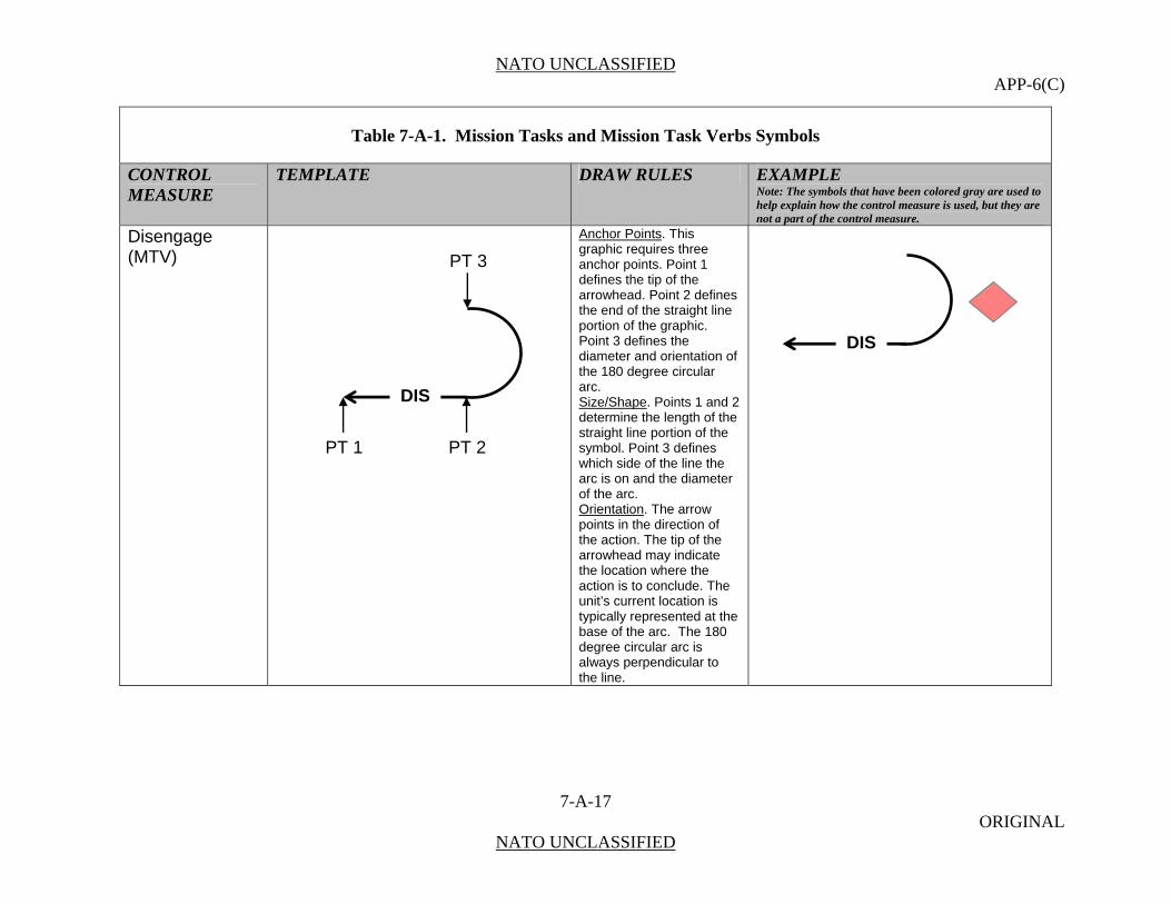
NATO UNCLASSIFIED APP-6(C)
7-A-17 ORIGINAL
NATO UNCLASSIFIED
Table 7-A-1. Mission Tasks and Mission Task Verbs Symbols
CONTROL MEASURE
TEMPLATE DRAW RULES EXAMPLE Note: The symbols that have been colored gray are used to help explain how the control measure is used, but they are not a part of the control measure.
Disengage (MTV)
Anchor Points. This graphic requires three anchor points. Point 1 defines the tip of the arrowhead. Point 2 defines the end of the straight line portion of the graphic. Point 3 defines the diameter and orientation of the 180 degree circular arc. Size/Shape. Points 1 and 2 determine the length of the straight line portion of the symbol. Point 3 defines which side of the line the arc is on and the diameter of the arc. Orientation. The arrow points in the direction of the action. The tip of the arrowhead may indicate the location where the action is to conclude. The unit’s current location is typically represented at the base of the arc. The 180 degree circular arc is always perpendicular to the line.
PT 1
PT 3
PT 2
DIS
DIS

NATO UNCLASSIFIED APP-6(C)
7-A-18 ORIGINAL
NATO UNCLASSIFIED
Table 7-A-1. Mission Tasks and Mission Task Verbs Symbols
CONTROL MEASURE
TEMPLATE DRAW RULES EXAMPLE Note: The symbols that have been colored gray are used to help explain how the control measure is used, but they are not a part of the control measure.
Disrupt (MT/MTV) Break apart an enemy's formation and tempo, interrupt the enemy timetable, cause premature and/or piecemeal commitment of forces.
Anchor Points. This graphic requires three anchor points. Points 1 and 2 define the end points of the graphic’s vertical line. Point 3 defines the tip of the longest arrow. Size/Shape. Points 1 and 2 determine the height of the graphic and point 3 determines its length. The spacing between the graphic’s arrows will stay proportional to the graphic’s vertical line. The length of the short arrows will remain in proportion to the length of the longest arrow. The arrows are perpendicular to the baseline (vertical line) and parallel to each other. Orientation. The arrows typically point toward enemy forces.
PT 3
PT 2
PT 1
D D
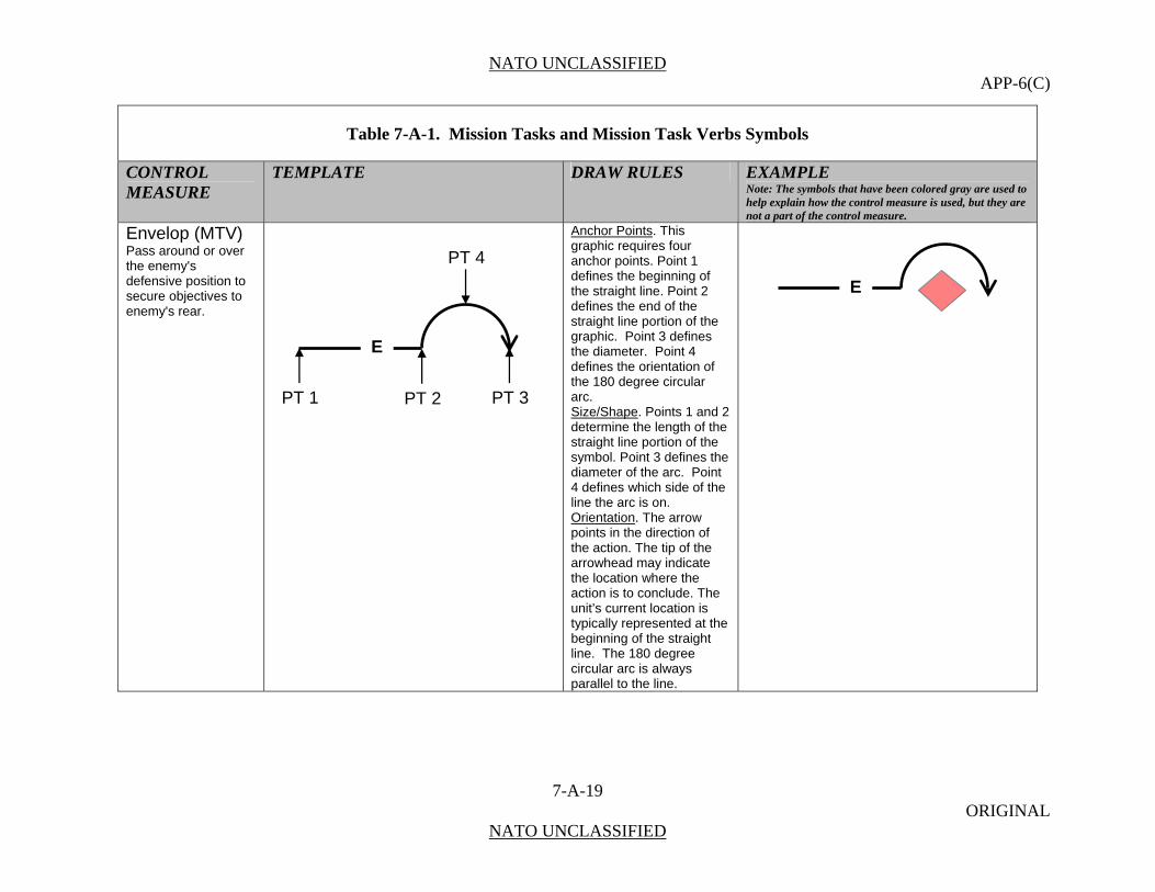
NATO UNCLASSIFIED APP-6(C)
7-A-19 ORIGINAL
NATO UNCLASSIFIED
Table 7-A-1. Mission Tasks and Mission Task Verbs Symbols
CONTROL MEASURE
TEMPLATE DRAW RULES EXAMPLE Note: The symbols that have been colored gray are used to help explain how the control measure is used, but they are not a part of the control measure.
Envelop (MTV) Pass around or over the enemy's defensive position to secure objectives to enemy's rear.
Anchor Points. This graphic requires four anchor points. Point 1 defines the beginning of the straight line. Point 2 defines the end of the straight line portion of the graphic. Point 3 defines the diameter. Point 4 defines the orientation of the 180 degree circular arc. Size/Shape. Points 1 and 2 determine the length of the straight line portion of the symbol. Point 3 defines the diameter of the arc. Point 4 defines which side of the line the arc is on. Orientation. The arrow points in the direction of the action. The tip of the arrowhead may indicate the location where the action is to conclude. The unit’s current location is typically represented at the beginning of the straight line. The 180 degree circular arc is always parallel to the line.
E
PT 1
E
PT 2 PT 3
PT 4

NATO UNCLASSIFIED APP-6(C)
7-A-20 ORIGINAL
NATO UNCLASSIFIED
Table 7-A-1. Mission Tasks and Mission Task Verbs Symbols
CONTROL MEASURE
TEMPLATE DRAW RULES EXAMPLE Note: The symbols that have been colored gray are used to help explain how the control measure is used, but they are not a part of the control measure.
Escort (MTV) Accompany and protect. (STANAG 2287) Note: Symbol is normally used in conjunction with convoy symbol.
Anchor Points. This graphic requires three anchor points. Point 1 defines the centre of the graphic. Point 2 and Point 3 defines the length of the escort. Size/Shape. Points 2 and 3 determine the length of the symbol. Orientation. The escort symbol appears above the convoy or escorted unit symbol.
Exfiltrate (MTV) Withdraw through or around enemy positions without detection. (STANAG 2287)
Anchor Points. This graphic requires three anchor points. Point 1 defines the end of the straight line portion of the graphic. Point 2 defines the centre of the two 90 degree circular arcs. Point 3 defines the tip of the arrowhead. Size/Shape. Points 1 and 3 determine the length of the symbol. Orientation. The arrow points in the direction of friendly forces. The tip of the arrowhead may indicate the location where the action is to conclude.
E EA
PT 1CENTRE POINT
PT 2 PT 3
E E
060500ZJUN07 –060800ZJUN07
12
PT 2
PT 3
EX
PT 1
EX
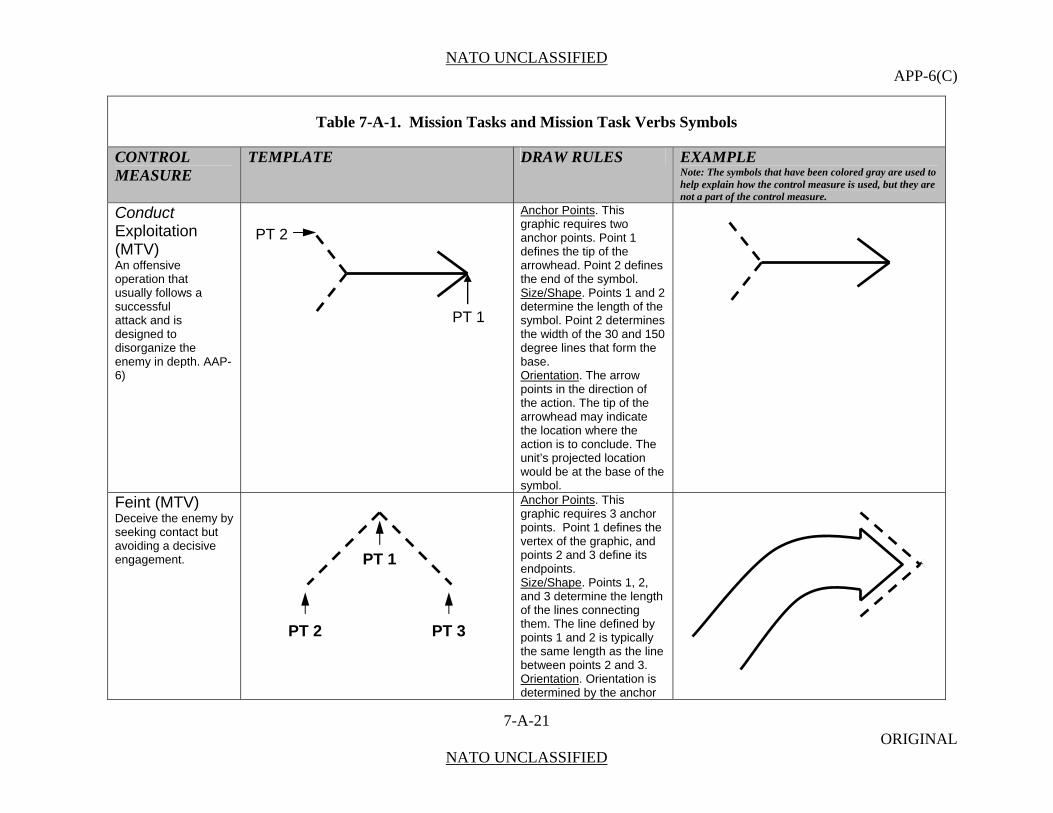
NATO UNCLASSIFIED APP-6(C)
7-A-21 ORIGINAL
NATO UNCLASSIFIED
Table 7-A-1. Mission Tasks and Mission Task Verbs Symbols
CONTROL MEASURE
TEMPLATE DRAW RULES EXAMPLE Note: The symbols that have been colored gray are used to help explain how the control measure is used, but they are not a part of the control measure.
Conduct Exploitation (MTV) An offensive operation that usually follows a successful attack and is designed to disorganize the enemy in depth. AAP-6)
Anchor Points. This graphic requires two anchor points. Point 1 defines the tip of the arrowhead. Point 2 defines the end of the symbol. Size/Shape. Points 1 and 2 determine the length of the symbol. Point 2 determines the width of the 30 and 150 degree lines that form the base. Orientation. The arrow points in the direction of the action. The tip of the arrowhead may indicate the location where the action is to conclude. The unit’s projected location would be at the base of the symbol.
Feint (MTV) Deceive the enemy by seeking contact but avoiding a decisive engagement.
Anchor Points. This graphic requires 3 anchor points. Point 1 defines the vertex of the graphic, and points 2 and 3 define its endpoints. Size/Shape. Points 1, 2, and 3 determine the length of the lines connecting them. The line defined by points 1 and 2 is typically the same length as the line between points 2 and 3. Orientation. Orientation is determined by the anchor
PT 1
PT 2
PT 2
PT 1
PT 3

NATO UNCLASSIFIED APP-6(C)
7-A-22 ORIGINAL
NATO UNCLASSIFIED
Table 7-A-1. Mission Tasks and Mission Task Verbs Symbols
CONTROL MEASURE
TEMPLATE DRAW RULES EXAMPLE Note: The symbols that have been colored gray are used to help explain how the control measure is used, but they are not a part of the control measure.
points. Fix (MT/MTV) Prevent an enemy from moving any part of his forces from a specified location for a specified period of time.
Anchor Points: This graphic requires 2 anchor points. Point 1 defines the tip of the arrowhead, and point 2 defines the rear of the graphic.2 Size/Shape: Points 1 and 2 determine the length of the graphic, which varies only in length. Orientation: The arrow points toward the enemy forces.
Follow and Assume (MT/MTV) Follow a force conducting an offensive operation, and be prepared to continue the mission if the lead force is fixed, or otherwise unable to continue.
Follow and Support (MT/MTV) Follow and support a lead force conducting an offensive operation.
Anchor Points. This graphic requires at least two points, points 1 and 2, to define the line. Additional points can be defined to extend and shape the line. Size/Shape. The first and last anchor points determine the length of the line. The graphic at the end of the line will contain the symbol of the unit that follows and assumes or follows and supports Orientation. Orientation is determined by the anchor points.
PT 1
A
PT 2
PT PT 1
A
PT 2 PT 1
F F
X
I I I
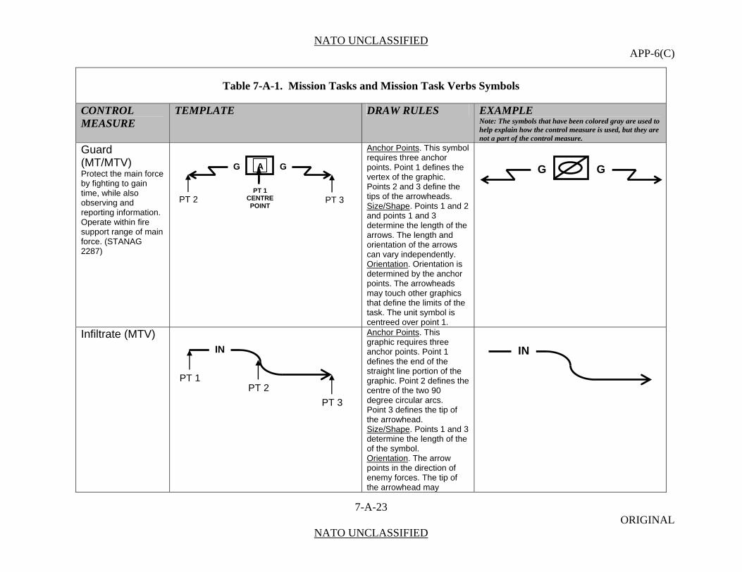
NATO UNCLASSIFIED APP-6(C)
7-A-23 ORIGINAL
NATO UNCLASSIFIED
Table 7-A-1. Mission Tasks and Mission Task Verbs Symbols
CONTROL MEASURE
TEMPLATE DRAW RULES EXAMPLE Note: The symbols that have been colored gray are used to help explain how the control measure is used, but they are not a part of the control measure.
Guard (MT/MTV) Protect the main force by fighting to gain time, while also observing and reporting information. Operate within fire support range of main force. (STANAG 2287)
Anchor Points. This symbol requires three anchor points. Point 1 defines the vertex of the graphic. Points 2 and 3 define the tips of the arrowheads. Size/Shape. Points 1 and 2 and points 1 and 3 determine the length of the arrows. The length and orientation of the arrows can vary independently. Orientation. Orientation is determined by the anchor points. The arrowheads may touch other graphics that define the limits of the task. The unit symbol is centreed over point 1.
Infiltrate (MTV)
Anchor Points. This graphic requires three anchor points. Point 1 defines the end of the straight line portion of the graphic. Point 2 defines the centre of the two 90 degree circular arcs. Point 3 defines the tip of the arrowhead. Size/Shape. Points 1 and 3 determine the length of the of the symbol. Orientation. The arrow points in the direction of enemy forces. The tip of the arrowhead may
G GA
PT 1 CENTRE POINT
PT 2 PT 3
G G
IN
PT 2
PT 3
PT 1
IN

NATO UNCLASSIFIED APP-6(C)
7-A-24 ORIGINAL
NATO UNCLASSIFIED
Table 7-A-1. Mission Tasks and Mission Task Verbs Symbols
CONTROL MEASURE
TEMPLATE DRAW RULES EXAMPLE Note: The symbols that have been colored gray are used to help explain how the control measure is used, but they are not a part of the control measure.
indicate the location where the action is to conclude.
Interdict (MT/MTV) Keep an enemy force out of range so that it cannot be used effectively against a friendly force. (STANAG 2287)
Anchor Points. This graphic requires one anchor point. The centre point defines centre of the graphic. Size/Shape. Static. Orientation. The graphic is typically centered over the desired location.
Isolate (MT/MTV) Seal off an enemy force from its sources of support, to deny it freedom of movement, and prevent it from having contact with other enemy forces. (STANAG 2287)
Anchor Points. This graphic requires two anchor points. Point 1 defines the centre point of the graphic and point 2 defines the graphic’s start point and radius. Size/Shape. The radius will be long enough for the graphic to encompass the area being isolated. The opening will be a 30 degree arc of the circle. Orientation. The opening will be on the friendly side of the graphic.
CENTER POINT
IPT 1
CENTER POINT
PT 2
I
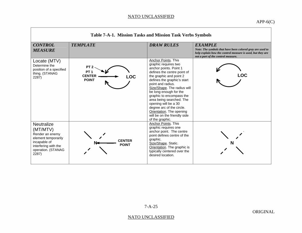
NATO UNCLASSIFIED APP-6(C)
7-A-25 ORIGINAL
NATO UNCLASSIFIED
Table 7-A-1. Mission Tasks and Mission Task Verbs Symbols
CONTROL MEASURE
TEMPLATE DRAW RULES EXAMPLE Note: The symbols that have been colored gray are used to help explain how the control measure is used, but they are not a part of the control measure.
Locate (MTV) Determine the position of a specified thing. (STANAG 2287)
Anchor Points. This graphic requires two anchor points. Point 1 defines the centre point of the graphic and point 2 defines the graphic’s start point and radius. Size/Shape. The radius will be long enough for the graphic to encompass the area being searched. The opening will be a 30 degree arc of the circle. Orientation. The opening will be on the friendly side of the graphic.
Neutralize (MT/MTV) Render an enemy element temporarily incapable of interfering with the operation. (STANAG 2287)
Anchor Points. This graphic requires one anchor point. The centre point defines centre of the graphic. Size/Shape. Static. Orientation. The graphic is typically centered over the desired location.
N
LOCPT 1
CENTER POINT
PT 2
LOC
NCENTER POINT

NATO UNCLASSIFIED APP-6(C)
7-A-26 ORIGINAL
NATO UNCLASSIFIED
Table 7-A-1. Mission Tasks and Mission Task Verbs Symbols
CONTROL MEASURE
TEMPLATE DRAW RULES EXAMPLE Note: The symbols that have been colored gray are used to help explain how the control measure is used, but they are not a part of the control measure.
Occupy (MT/MTV) Position a unit in a specified area without enemy opposition. (STANAG 2287)
Anchor Points. This graphic requires two anchor points. Point 1 defines the centre point of the graphic and point 2 defines the graphic’s start point and radius. Size/Shape. The radius will be long enough for the graphic to encompass the area being isolated. The opening will be a 30 degree arc of the circle. Orientation. The opening will be on the friendly side of the graphic.
Penetrate (MT/MTV) Break through enemy defence and disrupt the defensive system. (STANAG 2287)
Anchor Points. This graphic requires three anchor points. Points 1 and 2 define the endpoints of the graphic’s vertical line. Point 3 defines the rear of the graphic. Size/Shape. Points 1 and 2 determine the height of the graphic and point 3 determines its length. The arrow will project perpendicularly from the midpoint of the vertical line. Orientation. The arrow points toward enemy forces.
PT 1 CENTER POINT
PT 2
OO
PT 3
PT 1
PT 2

NATO UNCLASSIFIED APP-6(C)
7-A-27 ORIGINAL
NATO UNCLASSIFIED
Table 7-A-1. Mission Tasks and Mission Task Verbs Symbols
CONTROL MEASURE
TEMPLATE DRAW RULES EXAMPLE Note: The symbols that have been colored gray are used to help explain how the control measure is used, but they are not a part of the control measure.
Pursue (MTV) Catch or cut off a hostile force attempting to escape, with the aim of destroying it. (STANAG 2287) Note: Pursuit - An offensive operation designed to catch or cut off a hostile force attempting to escape, with the aim of destroying it. (AAP-6)
Anchor Points. This graphic requires three anchor points. Point 1 defines the beginning of the straight line. Point 2 defines the end of the straight line portion of the graphic. Point 3 defines the diameter and orientation of the 180 degree circular arc and the tip of the arrowhead. Size/Shape. Points 1 and 2 determine the length of the straight line portion of the symbol. Point 3 defines which side of the line the arc is on and the diameter of the arc. Orientation. The arrow points in the direction of the action. The unit’s current location is typically represented at the base of the line. The 180 degree circular arc is always perpendicular to the line.
P
PT 2PT 1
PT 3
P
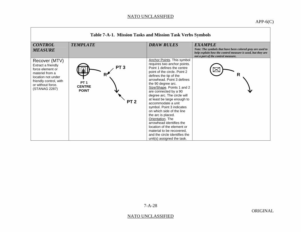
NATO UNCLASSIFIED APP-6(C)
7-A-28 ORIGINAL
NATO UNCLASSIFIED
Table 7-A-1. Mission Tasks and Mission Task Verbs Symbols
CONTROL MEASURE
TEMPLATE DRAW RULES EXAMPLE Note: The symbols that have been colored gray are used to help explain how the control measure is used, but they are not a part of the control measure.
Recover (MTV) Extract a friendly force element or materiel from a location not under friendly control, with or without force. (STANAG 2287)
Anchor Points. This symbol requires two anchor points. Point 1 defines the centre point of the circle. Point 2 defines the tip of the arrowhead. Point 3 defines the 90 degree arc. Size/Shape. Points 1 and 2 are connected by a 90 degree arc. The circle will at least be large enough to accommodate a unit symbol. Point 3 indicates on which side of the line the arc is placed. Orientation. The arrowhead identifies the location of the element or material to be recovered, and the circle identifies the unit(s) assigned the task.
R
PT 2
R
PT 1 CENTRE POINT
PT 3A

NATO UNCLASSIFIED APP-6(C)
7-A-29 ORIGINAL
NATO UNCLASSIFIED
Table 7-A-1. Mission Tasks and Mission Task Verbs Symbols
CONTROL MEASURE
TEMPLATE DRAW RULES EXAMPLE Note: The symbols that have been colored gray are used to help explain how the control measure is used, but they are not a part of the control measure.
Relief In Place (MT/MTV) An operation in which, by direction of higher authority, all or part of a unit is replaced in an area by the incoming unit. The responsibilities of the replaced elements for the mission and the assigned zone of operations are transferred to the incoming unit. The incoming unit continues the operation as ordered.
Anchor Points. This graphic requires four anchor points. Point 1 defines the tip of the first arrowhead. Point 2 defines the end of the straight line portion of the first arrow. Point 3 defines the tip of the second arrowhead. Point 4 defines the end of the second arrow. Size/Shape. Points 1 and 2, and points 3 and 4 determine the length of each arrow. Points 2 and 3 shall be connected by a smooth, curved line. Orientation. Determined by the anchor points. The unit being relieved is typically located at the base of the curve, and the unit performing the relief is typically located at the end of the symbol. The arrowhead typically points to the location the relieved unit should move to.
PT 1
PT 3
PT 2
RIP
PT 4 RIP
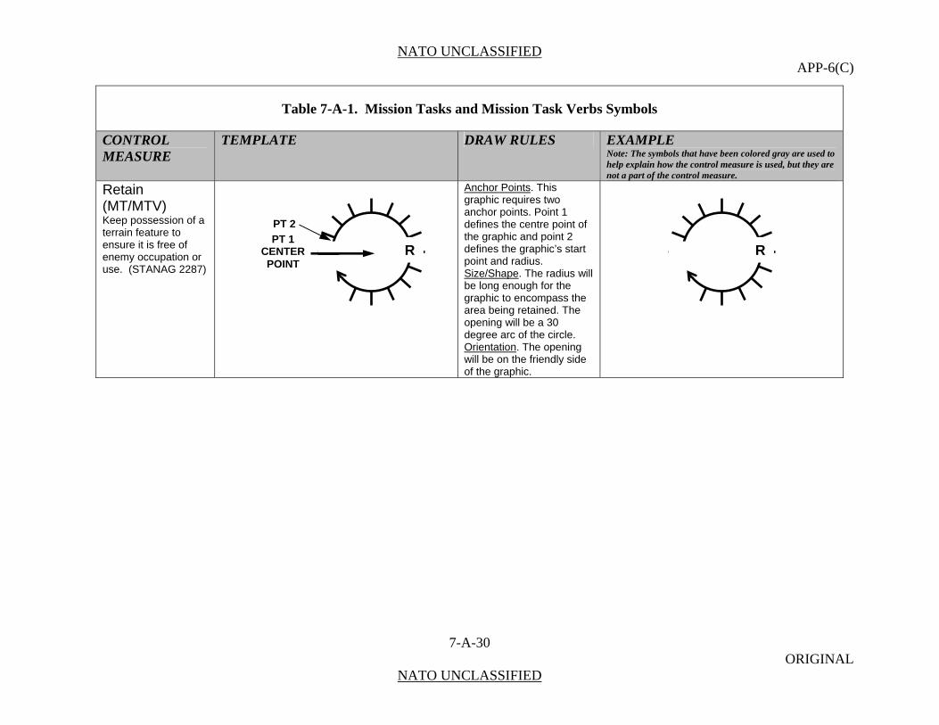
NATO UNCLASSIFIED APP-6(C)
7-A-30 ORIGINAL
NATO UNCLASSIFIED
Table 7-A-1. Mission Tasks and Mission Task Verbs Symbols
CONTROL MEASURE
TEMPLATE DRAW RULES EXAMPLE Note: The symbols that have been colored gray are used to help explain how the control measure is used, but they are not a part of the control measure.
Retain (MT/MTV) Keep possession of a terrain feature to ensure it is free of enemy occupation or use. (STANAG 2287)
Anchor Points. This graphic requires two anchor points. Point 1 defines the centre point of the graphic and point 2 defines the graphic’s start point and radius. Size/Shape. The radius will be long enough for the graphic to encompass the area being retained. The opening will be a 30 degree arc of the circle. Orientation. The opening will be on the friendly side of the graphic.
RPT 1
CENTER POINT
PT 2
R

NATO UNCLASSIFIED APP-6(C)
7-A-31 ORIGINAL
NATO UNCLASSIFIED
Table 7-A-1. Mission Tasks and Mission Task Verbs Symbols
CONTROL MEASURE
TEMPLATE DRAW RULES EXAMPLE Note: The symbols that have been colored gray are used to help explain how the control measure is used, but they are not a part of the control measure.
Retire (MTV) Move a force, out of contact, away from the enemy. (STANAG 2287) Retirement (MT) An operation in which a force out of contact moves away from the enemy. (AAP-6)
Anchor Points. This graphic requires three anchor points. Point 1 defines the tip of the arrowhead. Point 2 defines the end of the straight line portion of the graphic. Point 3 defines the diameter and orientation of the 180 degree circular arc. Size/Shape. Points 1 and 2 determine the length of the straight line portion of the symbol. Point 3 defines which side of the line the arc is on and the diameter of the arc. Orientation. The arrow points in the direction of the action. The tip of the arrowhead may indicate the location where the action is to conclude. The unit’s current location is typically represented at the base of the arc. The 180 degree circular arc is always perpendicular to the line.
PT 1
R
PT 3
PT 2
R
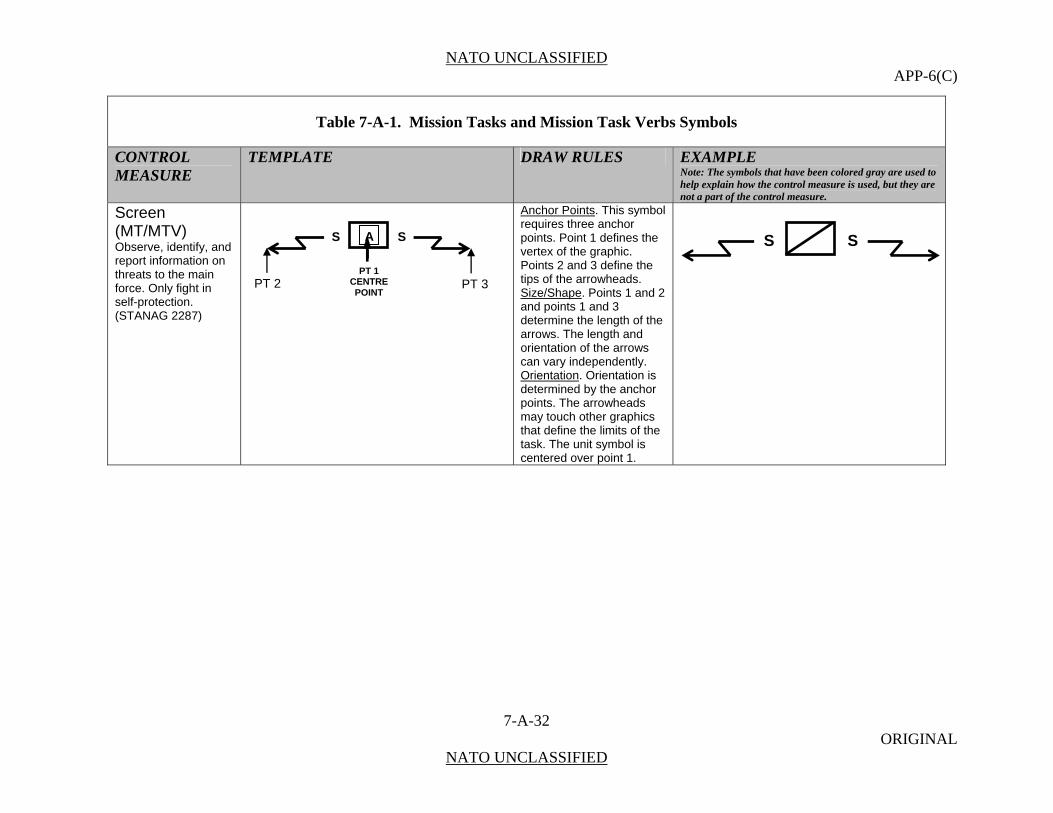
NATO UNCLASSIFIED APP-6(C)
7-A-32 ORIGINAL
NATO UNCLASSIFIED
Table 7-A-1. Mission Tasks and Mission Task Verbs Symbols
CONTROL MEASURE
TEMPLATE DRAW RULES EXAMPLE Note: The symbols that have been colored gray are used to help explain how the control measure is used, but they are not a part of the control measure.
Screen (MT/MTV) Observe, identify, and report information on threats to the main force. Only fight in self-protection. (STANAG 2287)
Anchor Points. This symbol requires three anchor points. Point 1 defines the vertex of the graphic. Points 2 and 3 define the tips of the arrowheads. Size/Shape. Points 1 and 2 and points 1 and 3 determine the length of the arrows. The length and orientation of the arrows can vary independently. Orientation. Orientation is determined by the anchor points. The arrowheads may touch other graphics that define the limits of the task. The unit symbol is centered over point 1.
S SA
PT 1 CENTRE POINT
PT 2 PT 3
S S

NATO UNCLASSIFIED APP-6(C)
7-A-33 ORIGINAL
NATO UNCLASSIFIED
Table 7-A-1. Mission Tasks and Mission Task Verbs Symbols
CONTROL MEASURE
TEMPLATE DRAW RULES EXAMPLE Note: The symbols that have been colored gray are used to help explain how the control measure is used, but they are not a part of the control measure.
Secure (MTV) Gain possession of a position or terrain feature, with or without force, and to make such disposition as will prevent its destruction or loss to enemy action. (STANAG 2287)
Secure (MT) In an operational context, to gain possession of a position or terrain feature, with or without force, and to make such disposition as will prevent, as far as possible, its destruction or loss by enemy action. (AAP-6)
Anchor Points. This graphic requires two anchor points. Point 1 defines the centre point of the graphic and point 2 defines the graphic’s start point and radius. Size/Shape. The radius will be long enough for the graphic to encompass the area being secured. The opening will be a 30 degree arc of the circle. Orientation. The opening will be on the friendly side of the graphic.
SPT 1
CENTER POINT
PT 2
S

NATO UNCLASSIFIED APP-6(C)
7-A-34 ORIGINAL
NATO UNCLASSIFIED
Table 7-A-1. Mission Tasks and Mission Task Verbs Symbols
CONTROL MEASURE
TEMPLATE DRAW RULES EXAMPLE Note: The symbols that have been colored gray are used to help explain how the control measure is used, but they are not a part of the control measure.
Seize (MT/MTV) Clear a designated area and obtain control of it. (STANAG 2287)
Anchor Points. This symbol requires two anchor points. Point 1 defines the centre point of the circle. Point 2 defines the tip of the arrowhead. Point 3 defines the 90 degree arc. Size/Shape. Points 1 and 2 are connected by a 90 degree arc. The circle will at least be large enough to accommodate a unit symbol. Point 3 indicates on which side of the line the arc is placed. Orientation. The arrowhead identifies the location to be seized, and the circle identifies the unit(s) assigned the task.
SA
PT 2
S
PT 1 CENTRE POINT
PT 3
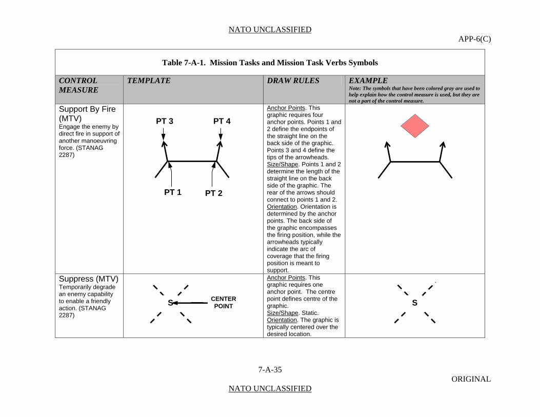
NATO UNCLASSIFIED APP-6(C)
7-A-35 ORIGINAL
NATO UNCLASSIFIED
Table 7-A-1. Mission Tasks and Mission Task Verbs Symbols
CONTROL MEASURE
TEMPLATE DRAW RULES EXAMPLE Note: The symbols that have been colored gray are used to help explain how the control measure is used, but they are not a part of the control measure.
Support By Fire (MTV) Engage the enemy by direct fire in support of another manoeuvring force. (STANAG 2287)
Anchor Points. This graphic requires four anchor points. Points 1 and 2 define the endpoints of the straight line on the back side of the graphic. Points 3 and 4 define the tips of the arrowheads. Size/Shape. Points 1 and 2 determine the length of the straight line on the back side of the graphic. The rear of the arrows should connect to points 1 and 2. Orientation. Orientation is determined by the anchor points. The back side of the graphic encompasses the firing position, while the arrowheads typically indicate the arc of coverage that the firing position is meant to support.
Suppress (MTV) Temporarily degrade an enemy capability to enable a friendly action. (STANAG 2287)
Anchor Points. This graphic requires one anchor point. The centre point defines centre of the graphic. Size/Shape. Static. Orientation. The graphic is typically centered over the desired location.
PT 3
PT 1 PT 2
PT 4
SSCENTER POINT

NATO UNCLASSIFIED APP-6(C)
7-A-36 ORIGINAL
NATO UNCLASSIFIED
Table 7-A-1. Mission Tasks and Mission Task Verbs Symbols
CONTROL MEASURE
TEMPLATE DRAW RULES EXAMPLE Note: The symbols that have been colored gray are used to help explain how the control measure is used, but they are not a part of the control measure.
Turn (MTV) Force an enemy from one direction of advance to another. (STANAG 2287)
Anchor Points: This symbol requires two anchor points. Point 1 defines the rear of the graphic. Point 2 defines the tip of the arrowhead. Point 3 defines the 90 degree arc. Size/Shape: Points 1 and 2 are connected by a 90 degree arc. Point 3 indicates on which side of the line the arc is placed. Orientation: The rear of the graphic identifies the enemy’s location and the arrow points in the direction the obstacle should force the enemy to turn.
Withdraw (MT/MTV) Disengage from the enemy and move in a direction away from the enemy. (STANAG 2287)
Anchor Points. This graphic requires three anchor points. Point 1defines the tip of the arrowhead. Point 2 defines the end of the straight line portion of the graphic. Point 3 defines the diameter and orientation of the 180 degree circular arc. Size/Shape. Points 1 and 2 determine the length of the straight line portion of the symbol. Point 3 defines
W
PT 2
PT 1 PT 3
TT
PT 1
W
PT 3
PT 2
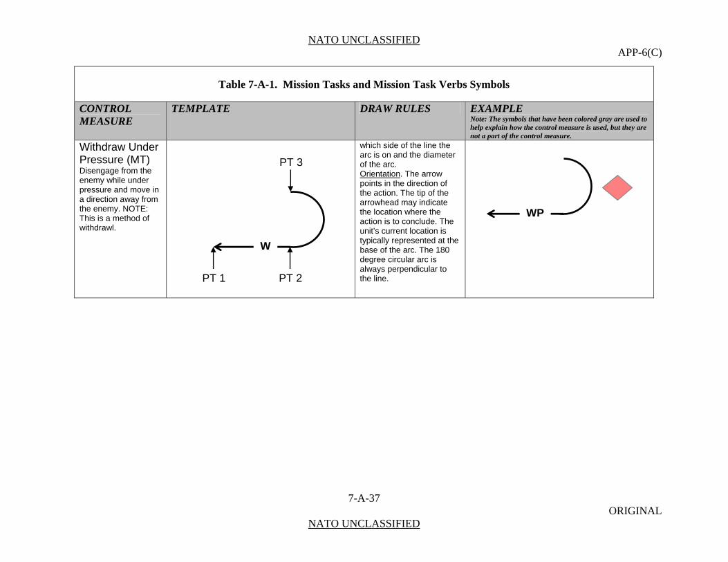
NATO UNCLASSIFIED APP-6(C)
7-A-37 ORIGINAL
NATO UNCLASSIFIED
Table 7-A-1. Mission Tasks and Mission Task Verbs Symbols
CONTROL MEASURE
TEMPLATE DRAW RULES EXAMPLE Note: The symbols that have been colored gray are used to help explain how the control measure is used, but they are not a part of the control measure.
Withdraw Under Pressure (MT) Disengage from the enemy while under pressure and move in a direction away from the enemy. NOTE: This is a method of withdrawl.
which side of the line the arc is on and the diameter of the arc. Orientation. The arrow points in the direction of the action. The tip of the arrowhead may indicate the location where the action is to conclude. The unit’s current location is typically represented at the base of the arc. The 180 degree circular arc is always perpendicular to the line.
WP
PT 1
W
PT 3
PT 2

NATO UNCLASSIFIED APP-6(C)
7-A-38 ORIGINAL
NATO UNCLASSIFIED
(INTENTIONALLY BLANK)
NATO UNCLASSIFIED APP-6(C)
8-1 ORIGINAL
NATO UNCLASSIFIED
CHAPTER 8
METEOROLOGICAL SYMBOLS
SECTION I - INTRODUCTION
Scope
0801. This chapter contains a structured set of symbols and graphics for the display of meteorological information.
Purpose
0802. For military operations, it is important to consider meteorological impacts as part of the environmental conditions. All meteorological parameters are strictly related to both time and space, and they could represent observations or forecasts. Therefore, it is recommended to display these sets in a separate layer.
0803. A meteorological symbol that displays an observation is always referred to a three-dimensional geographic point or to the vicinity of that point.
0804. A meteorological symbol that represents a weather prediction is often referred to a wider area which has to be delimited in a well-defined manner.
Content
0805. The set of meteorological symbols and graphics is based on approved symbols and icons from the World Meteorological Organization (WMO).

NATO UNCLASSIFIED APP-6(C)
8-2 ORIGINAL
NATO UNCLASSIFIED
SECTION II – WEATHER SYMBOLOGY
Table 8-1. Weather Graphics.
DESCRIPTION
WEATHER GRAPHIC
Pressure Systems
Low Pressure Centre
1. An area of low atmospheric pressure which has a closed circulation that is cyclonic, i.e., as viewed from above, the circulation is counter-clockwise in the Northern Hemisphere, clockwise in the Southern Hemisphere, or undefined at the Equator. Because cyclonic circulation and relatively low atmospheric pressure usually coexist, in common practice, the terms “cyclone” and “low” are used interchangeably. Also, because cyclones often are accompanied by inclement (sometimes destructive) weather, they are frequently referred to simply as storms. 2. Frequently misused to denote a tornado. 3. In the Indian Ocean, a tropical cyclone of hurricane or typhoon force.
L
High Pressure Centre
An area of high atmospheric pressure which has a closed circulation that is anti-cyclonic, i.e., as viewed from above, the circulation is clockwise in the Northern Hemisphere, counter-clockwise in the southern Hemisphere, or undefined at the Equator.
H
Frontal Systems
Cold Front
A zone separating two air masses, of which the cooler, denser mass is advancing and replacing the warmer.
Upper Cold Front
Occurs when discontinuity at the forward edge of an advancing cold air mass is displacing warmer air in its path and the two air masses intersect above ground level.
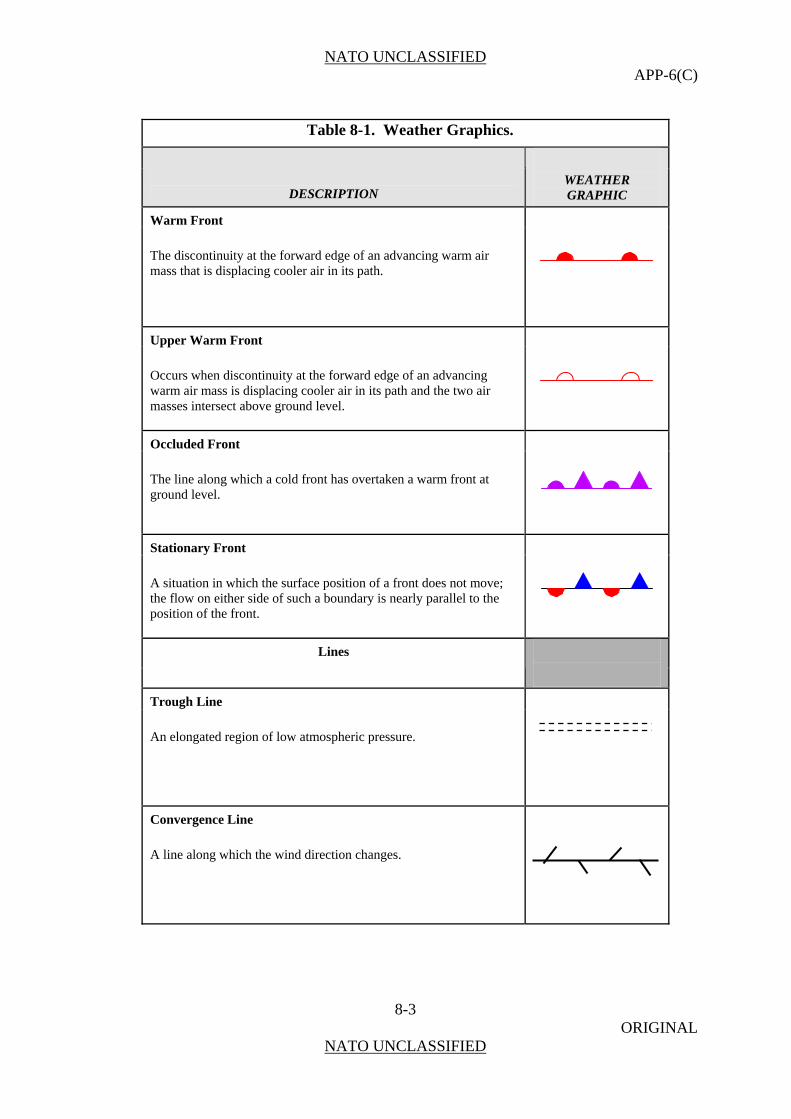
NATO UNCLASSIFIED APP-6(C)
8-3 ORIGINAL
NATO UNCLASSIFIED
Table 8-1. Weather Graphics.
DESCRIPTION
WEATHER GRAPHIC
Warm Front
The discontinuity at the forward edge of an advancing warm air mass that is displacing cooler air in its path.
Upper Warm Front
Occurs when discontinuity at the forward edge of an advancing warm air mass is displacing cooler air in its path and the two air masses intersect above ground level.
Occluded Front
The line along which a cold front has overtaken a warm front at ground level.
Stationary Front
A situation in which the surface position of a front does not move; the flow on either side of such a boundary is nearly parallel to the position of the front.
Lines
Trough Line
An elongated region of low atmospheric pressure.
Convergence Line
A line along which the wind direction changes.
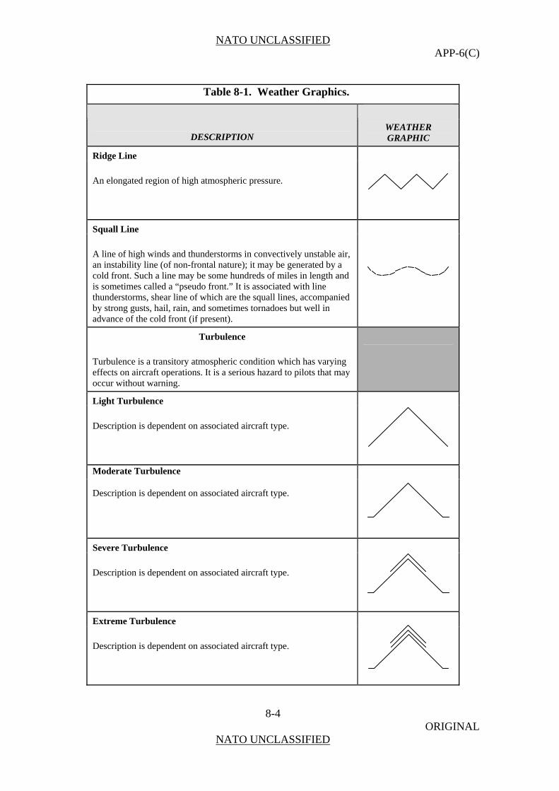
NATO UNCLASSIFIED APP-6(C)
8-4 ORIGINAL
NATO UNCLASSIFIED
Table 8-1. Weather Graphics.
DESCRIPTION
WEATHER GRAPHIC
Ridge Line
An elongated region of high atmospheric pressure.
Squall Line
A line of high winds and thunderstorms in convectively unstable air, an instability line (of non-frontal nature); it may be generated by a cold front. Such a line may be some hundreds of miles in length and is sometimes called a “pseudo front.” It is associated with line thunderstorms, shear line of which are the squall lines, accompanied by strong gusts, hail, rain, and sometimes tornadoes but well in advance of the cold front (if present).
Turbulence
Turbulence is a transitory atmospheric condition which has varying effects on aircraft operations. It is a serious hazard to pilots that may occur without warning.
Light Turbulence
Description is dependent on associated aircraft type.
Moderate Turbulence
Description is dependent on associated aircraft type.
Severe Turbulence
Description is dependent on associated aircraft type.
Extreme Turbulence
Description is dependent on associated aircraft type.

NATO UNCLASSIFIED APP-6(C)
8-5 ORIGINAL
NATO UNCLASSIFIED
Table 8-1. Weather Graphics.
DESCRIPTION
WEATHER GRAPHIC
Clear Icing
Glossy, clear, or translucent ice formed by the relatively slow freezing of large super cooled droplets. The droplets spread out over the airframe surface before completely freezing.
Light Clear Icing
Description is dependent on associated aircraft type.
Moderate Clear Icing
Description is dependent on associated aircraft type.
Severe Clear Icing
Description is dependent on associated aircraft type.
Rime Icing Rough, milky opaque ice formed by the instantaneous freezing of small super cooled droplets which trap air within the ice as they strike the aircraft.
Light Rime Icing
Description is dependent on associated aircraft type.
Moderate Rime Icing
Description is dependent on associated aircraft type.

NATO UNCLASSIFIED APP-6(C)
8-6 ORIGINAL
NATO UNCLASSIFIED
Table 8-1. Weather Graphics.
DESCRIPTION
WEATHER GRAPHIC
Severe Rime Icing
Description is dependent on associated aircraft type.
Mixed Icing A hard rough conglomerate of ice which can cause very rough accumulation and severe loss of lift.
Light Mixed Icing
Description is dependent on associated aircraft type.
Moderate Mixed Icing
Description is dependent on associated aircraft type.
Severe Mixed Icing
Description is dependent on associated aircraft type.
Wind Barb
Used, in different variations, to represent wind speeds.
Jet Stream
A narrow belt of strong winds, with speeds of 50 to 200 knots, in the upper troposphere. In the northern Hemisphere these winds usually have a westerly component.

NATO UNCLASSIFIED APP-6(C)
8-7 ORIGINAL
NATO UNCLASSIFIED
Table 8-1. Weather Graphics.
DESCRIPTION
WEATHER GRAPHIC
Flight Rules
Instrument Ceiling
Evaluation of ceiling height by cloud measuring equipment.
Visual Ceiling
The height above the earth's surface of the lowest (thin or opaque) layer reported as broken (5-7 oktas) or overcast (8 oktas), or the vertical visibility into an indefinite ceiling.
Coverage Symbols
Clear Sky (SKC)
The absence of layers of clouds or other obscuring phenomena.
SKC
Scattered Sky (SCT)
A summation sky cover of one-eighth through four-eighths.
Broken Sky (BKN)
A summation sky cover of five-eighths through seven-eighths.
Overcast (OVC)
A summation sky cover of eight-eighths
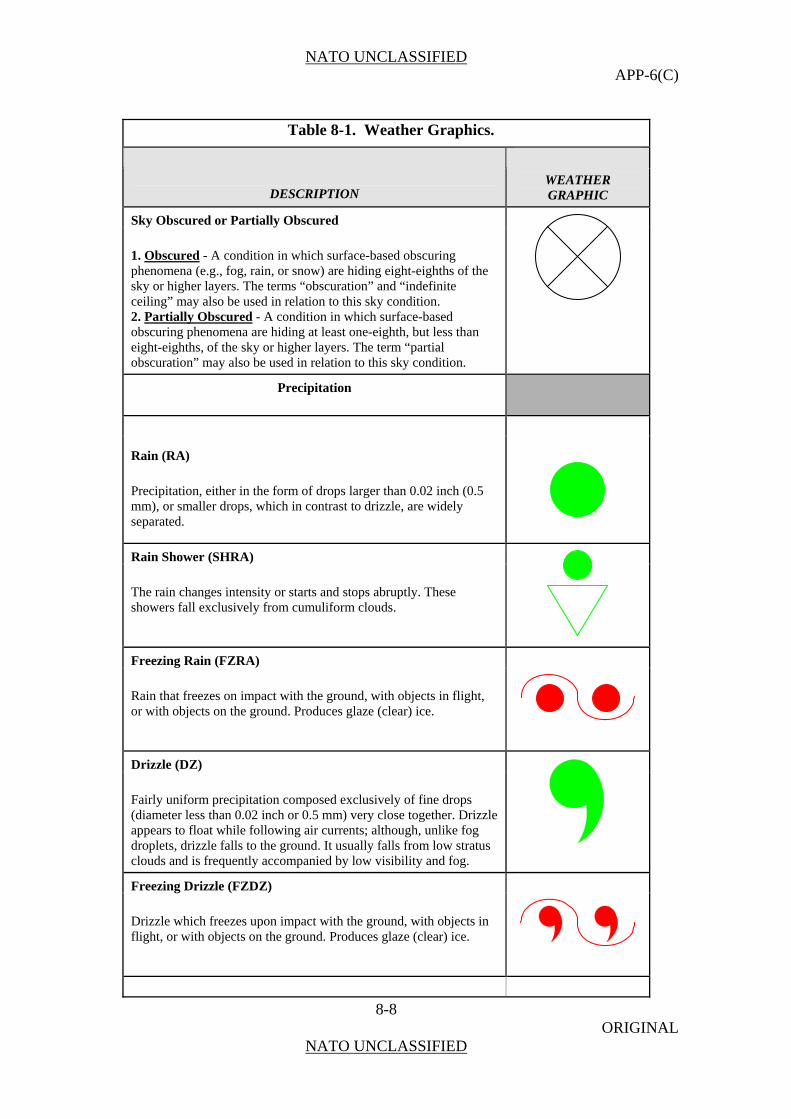
NATO UNCLASSIFIED APP-6(C)
8-8 ORIGINAL
NATO UNCLASSIFIED
Table 8-1. Weather Graphics.
DESCRIPTION
WEATHER GRAPHIC
Sky Obscured or Partially Obscured
1. Obscured - A condition in which surface-based obscuring phenomena (e.g., fog, rain, or snow) are hiding eight-eighths of the sky or higher layers. The terms “obscuration” and “indefinite ceiling” may also be used in relation to this sky condition. 2. Partially Obscured - A condition in which surface-based obscuring phenomena are hiding at least one-eighth, but less than eight-eighths, of the sky or higher layers. The term “partial obscuration” may also be used in relation to this sky condition.
Precipitation
Rain (RA)
Precipitation, either in the form of drops larger than 0.02 inch (0.5 mm), or smaller drops, which in contrast to drizzle, are widely separated.
Rain Shower (SHRA)
The rain changes intensity or starts and stops abruptly. These showers fall exclusively from cumuliform clouds.
Freezing Rain (FZRA)
Rain that freezes on impact with the ground, with objects in flight, or with objects on the ground. Produces glaze (clear) ice.
Drizzle (DZ)
Fairly uniform precipitation composed exclusively of fine drops (diameter less than 0.02 inch or 0.5 mm) very close together. Drizzle appears to float while following air currents; although, unlike fog droplets, drizzle falls to the ground. It usually falls from low stratus clouds and is frequently accompanied by low visibility and fog.
Freezing Drizzle (FZDZ)
Drizzle which freezes upon impact with the ground, with objects in flight, or with objects on the ground. Produces glaze (clear) ice.

NATO UNCLASSIFIED APP-6(C)
8-9 ORIGINAL
NATO UNCLASSIFIED
Table 8-1. Weather Graphics.
DESCRIPTION
WEATHER GRAPHIC
Snow (SN)
Precipitation of snow crystals, mostly branched in the form of six-pointed stars, many times clustered to form snowflakes.
Snow Showers (SHSN)
Snow changes intensity or starts and stops abruptly. These showers fall exclusively from cumuliform clouds.
Snow Grains (SG)
Precipitation of very small, white, opaque particles of ice; the solid equivalent of drizzle. The grains are fairly flat or elongated. Diameters are generally less than .04 inch (1mm). When the grains hit hard ground, they do not bounce or shatter. They usually fall in very small quantities from stratus clouds (or occasionally from fog).
Hail (SHGS)
Precipitation in the form of small balls or other pieces of ice falling separately or frozen together in irregular lumps. Hailstones consist of alternate opaque and clear layers of ice in most cases. Hail is normally associated with thunderstorms and surface temperatures above freezing.
Ice Pellets (PL)
Precipitation of transparent or translucent pellets of ice, which are round or irregular, rarely conical, and have a diameter of 0.2 inch (5 mm) or less. The pellets usually rebound when striking hard ground and make a sound on impact. They are two main types. Hard grains of ice consisting of frozen raindrops or melted and refrozen snowflakes and pellets of snow encased in a thin layer of ice formed from the freezing, either of droplets intercepted by the pellets or of water resulting from the partial melting of the pellets.
Ice Crystals (IC)
A fall of unbranched (snow crystals are branched) ice crystals in the form of needles, columns, or plates. They are termed “ice prisms” in Synoptic observations. Ice crystals are often so tiny they seem to be suspended in the air. They may fall from a cloud or from clear air. The crystals are visible mainly when they glitter in the sunshine or other bright light (diamond dust), thus producing a luminous pillar or other optical phenomena. This hydrometeor (rarely more than the lightest precipitation), which is frequent in polar regions, occurs only at very low temperatures in stable air masses.

NATO UNCLASSIFIED APP-6(C)
8-10 ORIGINAL
NATO UNCLASSIFIED
Table 8-1. Weather Graphics.
DESCRIPTION
WEATHER GRAPHIC
Storms
Thunderstorm (TS)
A local storm produced by a cumulonimbus cloud accompanied by strong, gusty winds; vertical currents at higher levels; and heavy precipitation with lightning and/or thunder. It is usually a few miles in both horizontal and vertical dimensions, extending from the ground up to 20,000, 40,000, or even 60,000 feet in the most vigorous examples.
Thunderstorm (TS) and Rain (RA)
A local storm produced by a cumulonimbus cloud accompanied by lightning and/or thunder and precipitation, either in the form of drops larger than 0.02 inch (0.5 mm) or smaller drops, which in contrast to drizzle, are widely separated.
Funnel Cloud (FC) / Tornado / Waterspout
1. Funnel Cloud (FC) - A violent, rotating column of air which does not touch the ground, usually appended to a cumulonimbus cloud. Also called a tuba.
2. Tornado - (+FC) - A violent, rotating column of air touching the ground; funnel cloud touching the ground. A tornado nearly always starts as a funnel cloud (FC) and is accompanied by a loud, roaring noise.
3. Waterspout (+FC) - A violent, rotating column of air that forms over a body of water, such as a bay, gulf, or lake and touches the water surface; a tornado or funnel cloud that touches a body of water.
Lightning (LTG)
A luminous manifestation accompanying a sudden electrical discharge which takes place from or inside a cloud or, less often, from high structures on the ground or from mountains.
Storm Systems
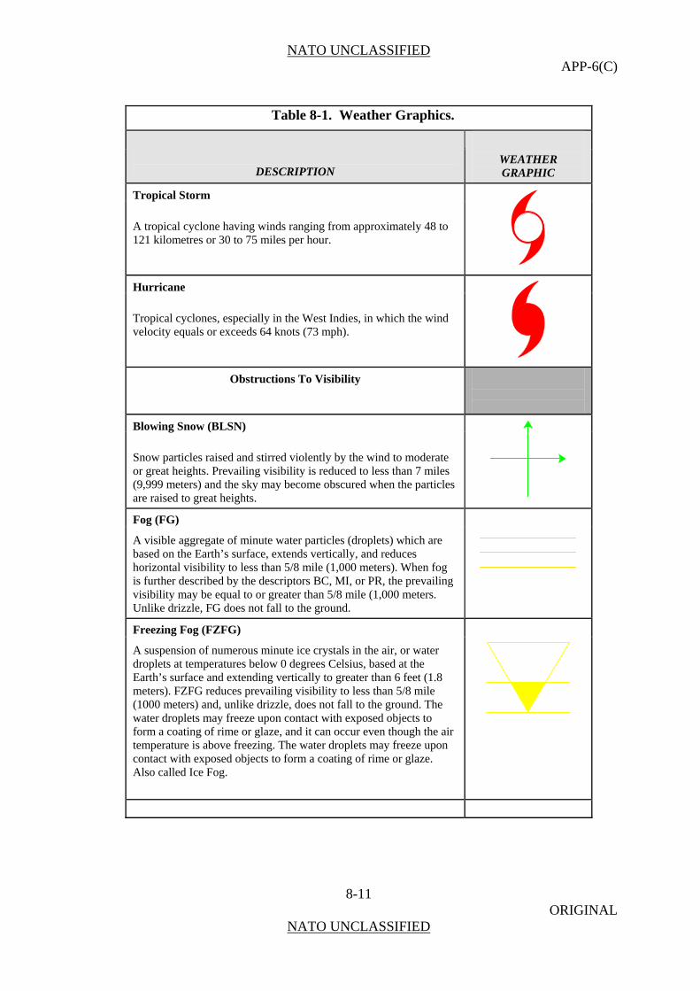
NATO UNCLASSIFIED APP-6(C)
8-11 ORIGINAL
NATO UNCLASSIFIED
Table 8-1. Weather Graphics.
DESCRIPTION
WEATHER GRAPHIC
Tropical Storm
A tropical cyclone having winds ranging from approximately 48 to 121 kilometres or 30 to 75 miles per hour.
Hurricane
Tropical cyclones, especially in the West Indies, in which the wind velocity equals or exceeds 64 knots (73 mph).
Obstructions To Visibility
Blowing Snow (BLSN)
Snow particles raised and stirred violently by the wind to moderate or great heights. Prevailing visibility is reduced to less than 7 miles (9,999 meters) and the sky may become obscured when the particles are raised to great heights.
Fog (FG)
A visible aggregate of minute water particles (droplets) which are based on the Earth’s surface, extends vertically, and reduces horizontal visibility to less than 5/8 mile (1,000 meters). When fog is further described by the descriptors BC, MI, or PR, the prevailing visibility may be equal to or greater than 5/8 mile (1,000 meters. Unlike drizzle, FG does not fall to the ground.
Freezing Fog (FZFG)
A suspension of numerous minute ice crystals in the air, or water droplets at temperatures below 0 degrees Celsius, based at the Earth’s surface and extending vertically to greater than 6 feet (1.8 meters). FZFG reduces prevailing visibility to less than 5/8 mile (1000 meters) and, unlike drizzle, does not fall to the ground. The water droplets may freeze upon contact with exposed objects to form a coating of rime or glaze, and it can occur even though the air temperature is above freezing. The water droplets may freeze upon contact with exposed objects to form a coating of rime or glaze. Also called Ice Fog.

NATO UNCLASSIFIED APP-6(C)
8-12 ORIGINAL
NATO UNCLASSIFIED
Table 8-1. Weather Graphics.
DESCRIPTION
WEATHER GRAPHIC
Dust or Sand Storm
1. Duststorm (DS). An unusual, frequently severe weather condition characterized by strong winds and dust-filled air over an extensive area. Report a duststorm if the prevailing visibility is reduced to less than 5/8 miles (1,000 meters) but not less than 5/16 miles (500 meters). Report a heavy (severe) duststorm (+DS) if the visibility is reduced to less than 5/16 miles (500 meters).
2. Sandstorm (SS). Particles of sand ranging in diameter from 0.008 inches to 1 millimetres carried aloft by a strong wind. The sand particles are mostly confined to the lowest ten feet and rarely rise more than fifty feet above the ground. A sandstorm is reported if the prevailing visibility is reduced to less than 5/8 miles (1,000 meters) but not less than 5/16 miles (500 meters). Report a heavy (severe) sandstorm (+SS) if the visibility is reduced to less than 5/16 miles (500 meters).
Dust Devil
Well-developed dust/sand whirls (PO). An ensemble of particles of dust or sand, sometimes accompanied by small litter, raised from the ground in the form of a whirling column of varying height with a small diameter and an approximately vertical axis. Reported regardless of the visibility.
Smoke (FU)
A suspension in the air of small particles produced by combustion. A transition to haze may occur when smoke particles have travelled great distances (25 to 100 miles or 40 to 160 kilometres or more) and when the larger particles have settled out and the remaining particles have become widely scattered through the atmosphere. When viewed through smoke, the disk of the sun at sunrise and sunset appears very red. The disk may have an orange tinge when the sun is above the horizon. Evenly distributed smoke from distant sources generally has a light greyish or bluish appearance.
Haze (HZ)
A suspension in the air of extremely small, dry particles invisible to the naked eye and sufficiently numerous to give the air an opalescent appearance. This phenomenon resembles a uniform veil over the landscape and subdues all colours. Dark objects viewed through this veil tend to have a bluish tinge while bright objects, such as the sun or distant lights, tend to have a dirty yellow or reddish hue. When haze is present and the sun is well above the horizon, its light may have a peculiar silvery tinge. Haze particles may be composed of a variety of substances; e.g., dust, salt, residue from distant fires or volcanoes, pollen, etc., which generally are well diffused through the atmosphere.
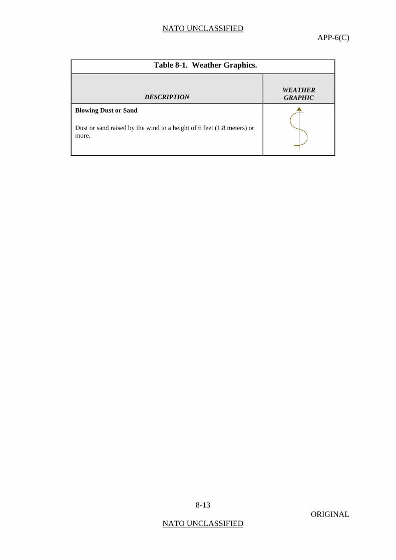
NATO UNCLASSIFIED APP-6(C)
8-13 ORIGINAL
NATO UNCLASSIFIED
Table 8-1. Weather Graphics.
DESCRIPTION
WEATHER GRAPHIC
Blowing Dust or Sand
Dust or sand raised by the wind to a height of 6 feet (1.8 meters) or more.

NATO UNCLASSIFIED APP-6(C)
8-14 ORIGINAL
NATO UNCLASSIFIED
(INTENTIONALLY BLANK)
NATO UNCLASSIFIED APP-6(C)
A-1 ORIGINAL
NATO UNCLASSIFIED
ANNEX A
SYMBOL IDENTIFICATION CODES
Purpose A001. When published this annex will outline the procedures for determining symbol identification codes (SIDC) for symbols in APP-6(C). It will be published at a later date. Countries that use SIDCs should continue to use the codes in APP-6(B) until this annex is published.
Symbol Identification Codes
A002. A symbol identification code is an alphanumeric code based on a database structure that provides the minimum elements required to construct the basic icon and/or a complete symbol.

NATO UNCLASSIFIED APP-6(C)
A-2 ORIGINAL
NATO UNCLASSIFIED
(INTENTIONALLY BLANK)
NATO UNCLASSIFIED APP-6(C)
B - 1 ORIGINAL
NATO UNCLASSIFIED
ANNEX B
COMPARATIVE FORMATION/UNIT DESIGNATIONS
General
B001. The data given in this Annex has been provided by each nation. The designations assigned by the various nations to their formations/units are shown against the agreed size symbols listed in Table II in Chapter 2 of this document. If a nation has no formation unit of the size indicated by the symbol, no designation will be entered. Nations not yet included in this Annex are invited to provide their unit designations. With a view to making this Annex easier to understand, each military symbol is accompanied by a group number, which is explained at the end of the Annex.
Explanatory Notes
B002. These group numbers should not be used outside the context of this STANAG. They are not intended as definitions in themselves.
a. Group 1. The smallest basic unit, part of a group 2 and/or a group 3 unit. Requires administrative and logistical support.
b. Group 2. A unit larger than a group 1 unit but smaller than a group 3 unit. Requires administrative and logistical support.
c. Group 3. A unit designed to perform a tactical or support mission, composed of two or more group 1 and/or group 2 units and normally forming part of a group 4 unit. It is commanded by an OF-1/OF-2 or OR-7/OR-8 (see STANAG 2116) and may or may not require administrative support.
d. Group 4. A unit designed to be capable of administering itself if operating independently and may be self-accounting. It is composed of two or more group 3 units and is commanded by an OF-2 or 3 (see STANAG 2116). It is normally part of a group 5 unit. It can be a composite group 4 unit of mixed arms.
e. Group 5. A unit designed to be self-administering and self-accounting and capable of operating independently. It is composed of two or more group 4 units and is commanded by an OF-3 or 4 (see STANAG 2116). It can be grouped with group 1, 2, 3 or 4 units of different arms to form a composite group 5 unit of mixed arms.
f. Group 6. A unit of two or more group 5 units or group 4 units usually of the same arm under a designated commander. Usually commanded by an OF-4, 5 or 6 (see STANAG 2116).
g. Group 7. A formation of two more combat arm group 5 units or group 6 units with group 1, 2, 3, 4 or 5 units from supporting arms and services normally commanded by an OF-5 or 6 (see STANAG 2116); it is smaller than a group 8 formation.
NATO UNCLASSIFIED APP-6(C)
B - 2 ORIGINAL
NATO UNCLASSIFIED
h. Group 8. A major tactical and administrative formation which combines in itself the necessary arms and services required for sustained combat, larger than a group 7 formation and smaller than a group 9 formation. It is normally commanded by an OF-7 (see STANAG 2116).
i. Group 9. A formation larger than a group 8 formation and smaller than a group 10 formation which usually consists of two or more group 8 formations together with supporting arms and services. It is normally commanded by OF-8 (see STANAG 2116).
j. Group 10. The largest tactical and administrative formation of armed forces made up of a number of group 9 and group 8 formations.
k. Group 11. Several group 10 or group 9 formations under a designated joint force commander.

NATO UNCLASSIFIED APP-6(C)
B - 3 ORIGINAL
NATO UNCLASSIFIED
GROUP SYMBOL NATIONAL DESIGNATION REMARK COUNTRY 1
• ALB
2
• •
3
• • •
4
I
5
I I
6
I I I
7
8
9
10
11

NATO UNCLASSIFIED APP-6(C)
B - 4 ORIGINAL
NATO UNCLASSIFIED
GROUP SYMBOL NATIONAL DESIGNATION REMARK COUNTRY FRANCAISE NEERLANDAISE BEL
1 •
Equipe Ploeg (1)
2 • •
Section Sectie (1)
3 • • •
Peloton Peloton (1)
4
I
Compagnie Escadron Batterie
Compagnie Eskadron Batterij
(1) armor artillery
5
I I Bataillon Escadrille
Bataljon Escadrille
(1) army aviation
6
I I I Groupement Regiment
Groepering Regiment
Applies only to home forces
7
Brigade Brigade (1)
8
Division Divisie (1)
9
Corps d’armée Legerkorps (1)
10
Armée Leger (2)
11
Group d’armée
Legergroep (2)
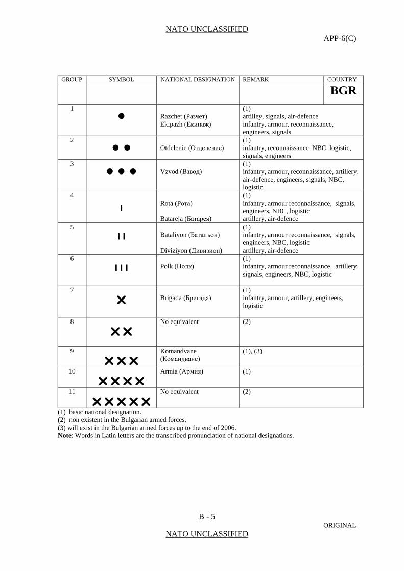
NATO UNCLASSIFIED APP-6(C)
B - 5 ORIGINAL
NATO UNCLASSIFIED
GROUP SYMBOL NATIONAL DESIGNATION REMARK COUNTRY BGR
1 •
Razchet (Paзҹeт) Ekipazh (Eҝипаҗ)
(1) artilley, signals, air-defence infantry, armour, reconnaissance, engineers, signals
2 • •
Otdelenie (Отделение)
(1) infantry, reconnaissance, NBC, logistic, signals, engineers
3 • • •
Vzvod (Взвод)
(1) infantry, armour, reconnaissance, artillery, air-defence, engineers, signals, NBC, logistic,
4
I
Rota (Рота) Batareja (Батарея)
(1) infantry, armour reconnaissance, signals, engineers, NBC, logistic artillery, air-defence
5
I I Bataliyon (Баталъон) Diviziyon (Дивизион)
(1) infantry, armour reconnaissance, signals, engineers, NBC, logistic artillery, air-defence
6
I I I Polk (Полк)
(1) infantry, armour reconnaissance, artillery, signals, engineers, NBC, logistic
7
Brigada (Бригада)
(1) infantry, armour, artillery, engineers, logistic
8
No equivalent (2)
9
Komandvane (Командване)
(1), (3)
10
Armia (Армия) (1)
11
No equivalent (2)
(1) basic national designation. (2) non existent in the Bulgarian armed forces. (3) will exist in the Bulgarian armed forces up to the end of 2006. Note: Words in Latin letters are the transcribed pronunciation of national designations.
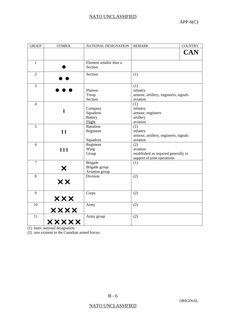
NATO UNCLASSIFIED APP-6(C)
B - 6 ORIGINAL
NATO UNCLASSIFIED
GROUP SYMBOL NATIONAL DESIGNATION REMARK COUNTRY CAN
1 •
Element smaller than a Section
2 • •
Section
(1)
3 • • •
Platoon Troop Section
(1) infantry armour, artillery, engineers, signals aviation
4
I
Company Squadron Battery Flight
(1) infantry armour, engineers artillery aviation
5
I I Battalion Regiment Squadron
(1) infantry armour, artillery, engineers, signals aviation
6
I I I Regiment Wing Group
(2) aviation established as required generally in support of joint operations
7
Brigade Brigade group Aviation group
(1)
8
Division (2)
9
Corps (2)
10
Army (2)
11
Army group (2)
(1) basic national designation. (2) non existent in the Canadian armed forces.
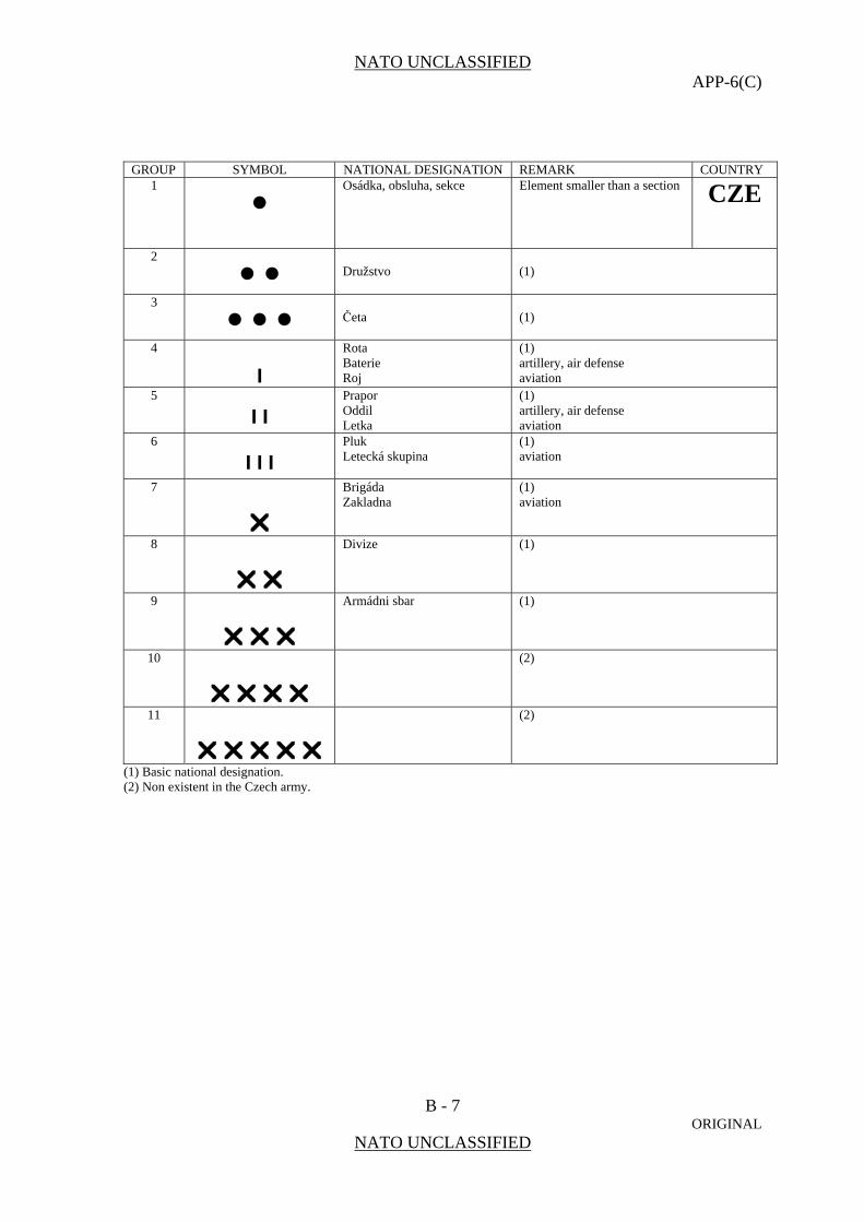
NATO UNCLASSIFIED APP-6(C)
B - 7 ORIGINAL
NATO UNCLASSIFIED
GROUP SYMBOL NATIONAL DESIGNATION REMARK COUNTRY 1
• Osádka, obsluha, sekce Element smaller than a section
CZE
2
• • Družstvo
(1)
3
• • • Četa
(1)
4
I
Rota Baterie Roj
(1) artillery, air defense aviation
5
I I Prapor Oddil Letka
(1) artillery, air defense aviation
6
I I I Pluk Letecká skupina
(1) aviation
7
Brigáda Zakladna
(1) aviation
8
Divize (1)
9
Armádni sbar (1)
10
(2)
11
(2)
(1) Basic national designation. (2) Non existent in the Czech army.
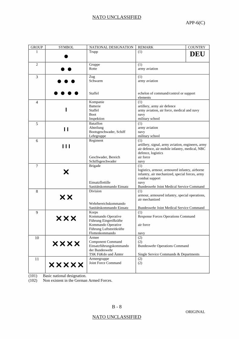
NATO UNCLASSIFIED APP-6(C)
B - 8 ORIGINAL
NATO UNCLASSIFIED
GROUP SYMBOL NATIONAL DESIGNATION REMARK COUNTRY 1
•
Trupp (1) DEU
2
• •
Gruppe Rotte
(1) army aviation
3 • • • • • • •
Zug Schwarm Staffel
(1) army aviation echelon of command/control or support elements
4
I
Kompanie Batterie Staffel Boot Inspektion
(1) artillery, army air defence army aviation, air force, medical and navy navy military school
5
I I Bataillon Abteilung Bootsgeschwader, Schiff Lehrgruppe
(1) army aviation navy military school
6
I I I Regiment Geschwader, Bereich Schiffsgeschwader
(1) artillery, signal, army aviation, engineers, army air defence, air mobile infantry, medical, NBC defence, logistics air force navy
7
Brigade Einsatzflottille Sanitätskommando Einsatz
(1) logistics, armour, armoured infantry, airborne infantry, air mechanized, special forces, army combat support navy Bundeswehr Joint Medical Service Command
8
Division Wehrbereichskommando Sanitätskommando Einsatz
(1) armour, armoured infantry, special operations, air mechanized Bundeswehr Joint Medical Service Command
9
Korps Kommando Operative Führung Eingreifkräfte Kommando Operative Führung Luftstreitkräfte Flottenkommando
(1) Response Forces Operations Command air force navy
10
Armee Component Command Einsatzführungskommando der Bundeswehr TSK FüKdo und Ämter
(2) (2) Bundeswehr Operations Command Single Service Commands & Departments
11
Armeegruppe Joint Force Command
(2) (2)
(101) Basic national designation. (102) Non existent in the German Armed Forces.
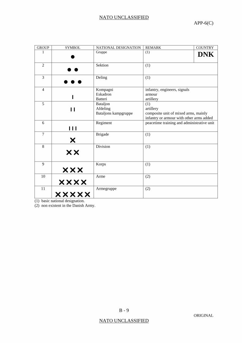
NATO UNCLASSIFIED APP-6(C)
B - 9 ORIGINAL
NATO UNCLASSIFIED
GROUP SYMBOL NATIONAL DESIGNATION REMARK COUNTRY 1
•
Gruppe (1) DNK
2 • •
Sektion
(1)
3 • • •
Deling (1)
4
I
Kompagni Eskadron Batteri
infantry, engineers, signals armour artillery
5
I I Bataljon Afdeling Bataljons kampgruppe
(1) artillery composite unit of mixed arms, mainly infantry or armour with other arms added
6
I I I Regiment
peacetime training and administrative unit
7
Brigade
(1)
8
Division (1)
9
Korps (1)
10
Arme (2)
11
Armegruppe (2)
(1) basic national designation. (2) non existent in the Danish Army.

NATO UNCLASSIFIED APP-6(C)
B - 10 ORIGINAL
NATO UNCLASSIFIED
GROUP SYMBOL NATIONAL DESIGNATION REMARK COUNTRY 1
• Escuadra/Equipo Patrulla
(1) army air ESP
2
• • Peloton
3
• • • Seccion
4
I
Compania Bateria Escuadron Subgrupo Tactico
(1) artillery armour composite unit of mixed arms
5
I I Battallon Grupo Grupo Tactico
(1) artillery, cavalry, services composite unit of mixed arms
6
I I I Regimiento Agrupacion Tactica
(1) composite unit of mixed arms
7
Brigada
(1)
8
Division (1)
9
Cuerpo de Ejercito (1)
10
Ejercito (2)
11
Grupo de Ejercito (2)
(1) basic national designation. (2) non existent in the Spanish army.

NATO UNCLASSIFIED APP-6(C)
B - 11 ORIGINAL
NATO UNCLASSIFIED
GROUP SYMBOL NATIONAL DESIGNATION REMARK COUNTRY EST
1 •
2 • •
3 • • •
4
I
5
I I
6
I I I
7
8
9
10
11
.
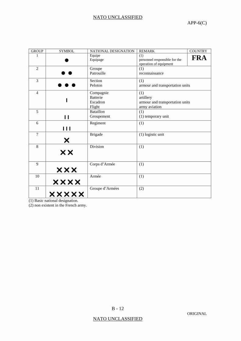
NATO UNCLASSIFIED APP-6(C)
B - 12 ORIGINAL
NATO UNCLASSIFIED
GROUP SYMBOL NATIONAL DESIGNATION REMARK COUNTRY 1
•
Equipe Equipage
(1) personnel responsible for the operation of equipment
FRA
2 • •
Groupe Patrouille
(1) reconnaissance
3 • • •
Section Peloton
(1) armour and transportation units
4
I
Compagnie Batterie Escadron Flight
(1) artillery armour and transportation units army aviation
5
I I Bataillon Groupement
(1) (1) temporary unit
6
I I I Regiment
(1)
7
Brigade
(1) logistic unit
8
Division (1)
9
Corps d’Armée (1)
10
Armée (1)
11
Groupe d’Armées (2)
(1) Basic national designation. (2) non existent in the French army.

NATO UNCLASSIFIED APP-6(C)
B - 13 ORIGINAL
NATO UNCLASSIFIED
GROUP SYMBOL NATIONAL DESIGNATION REMARK COUNTRY 1
• Section (1)
GBR
2
• • (2)
3
• • • Platoon Troop Flight
(1) marines, armour, artillery, engineers, signals, special air service, transport, army air, RAF Regiment
4
I
Company Squadron Battery Combat group. Squadron group, Coy/Sqn group
(1) armour, engineers, signals, special air service, army air , transport, RAF Regiment
5
I I Battalion Regiment Field Ambulance Armoured or Field workshop Wing Battle group Commando
(1) armour, artillery, engineers, signals, special air service, army air medical repair and recovery RAF Regiment composite unit of mixed arms “marines”
6
I I I (2)
7
Field force/Brigade
(1)
8
Division (1)
9
Corps (1)
10
(2)
11
Army Group (1)
(1) basic national designation. (2) non existent in the British army.
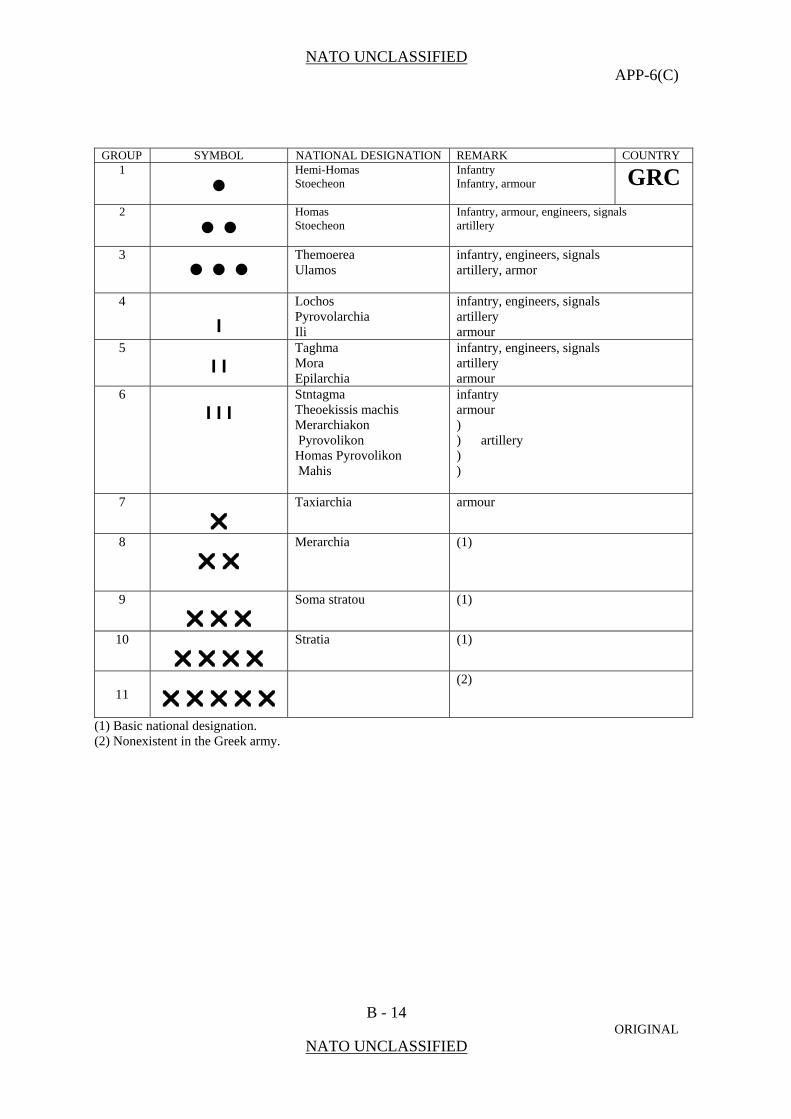
NATO UNCLASSIFIED APP-6(C)
B - 14 ORIGINAL
NATO UNCLASSIFIED
GROUP SYMBOL NATIONAL DESIGNATION REMARK COUNTRY 1
•
Hemi-Homas Stoecheon
Infantry Infantry, armour GRC
2
• •
Homas Stoecheon
Infantry, armour, engineers, signals artillery
3 • • •
Themoerea Ulamos
infantry, engineers, signals artillery, armor
4
I
Lochos Pyrovolarchia Ili
infantry, engineers, signals artillery armour
5
I I Taghma Mora Epilarchia
infantry, engineers, signals artillery armour
6
I I I Stntagma Theoekissis machis Merarchiakon Pyrovolikon Homas Pyrovolikon Mahis
infantry armour ) ) artillery ) )
7
Taxiarchia
armour
8
Merarchia (1)
9
Soma stratou (1)
10
Stratia (1)
11
(2)
(1) Basic national designation. (2) Nonexistent in the Greek army.

NATO UNCLASSIFIED APP-6(C)
B - 15 ORIGINAL
NATO UNCLASSIFIED
GROUP SYMBOL NATIONAL DESIGNATION REMARK COUNTRY 1
• HRV
2
• •
3
• • •
4
I
5
I I
6
I I I
7
8
9
10
11
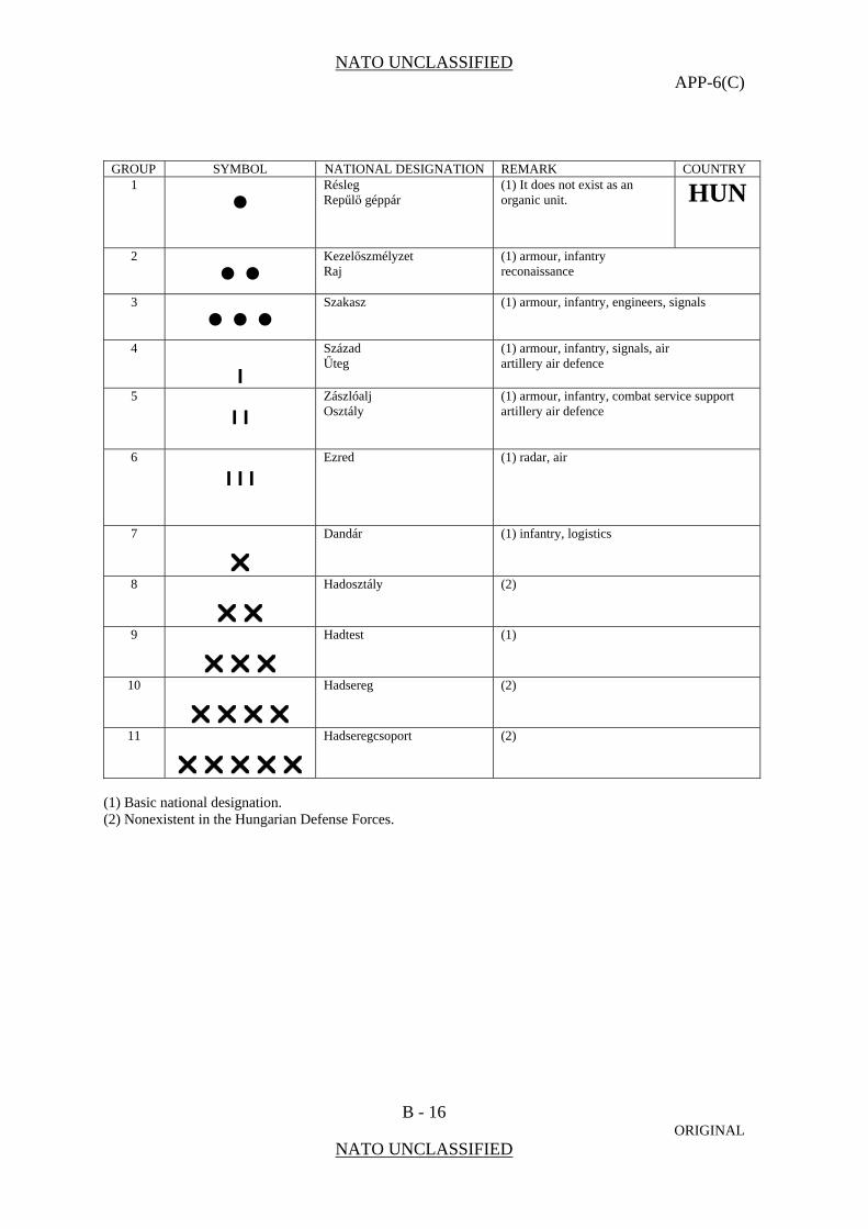
NATO UNCLASSIFIED APP-6(C)
B - 16 ORIGINAL
NATO UNCLASSIFIED
GROUP SYMBOL NATIONAL DESIGNATION REMARK COUNTRY 1
• Résleg Repűlő géppár
(1) It does not exist as an organic unit.
HUN
2
• • Kezelőszmélyzet Raj
(1) armour, infantry reconaissance
3
• • • Szakasz
(1) armour, infantry, engineers, signals
4
I
Század Űteg
(1) armour, infantry, signals, air artillery air defence
5
I I Zászlóalj Osztály
(1) armour, infantry, combat service support artillery air defence
6
I I I Ezred
(1) radar, air
7
Dandár
(1) infantry, logistics
8
Hadosztály (2)
9
Hadtest (1)
10
Hadsereg (2)
11
Hadseregcsoport (2)
(1) Basic national designation. (2) Nonexistent in the Hungarian Defense Forces.

NATO UNCLASSIFIED APP-6(C)
B - 17 ORIGINAL
NATO UNCLASSIFIED
GROUP SYMBOL NATIONAL DESIGNATION REMARK COUNTRY 1 •
ISL
2 • •
3 • • •
4
I
5
I I
6
I I I
7
8
9
10
11

NATO UNCLASSIFIED APP-6(C)
B - 18 ORIGINAL
NATO UNCLASSIFIED
GROUP SYMBOL NATIONAL DESIGNATION REMARK COUNTRY 1
•
Squadra Squadra pezzo Equipaggio
(1) artillery tank and cavalry
ITA
2
• •
Pattuglia This formation is not an organic unit. A comparable unit is organized on a case by case basis in accordance with the task. The unit strength may range from group 1 to 3.
3 • • •
Plotone Sezione
(1) artillery, transport
4
I
Compagnia Squadrone Batteria Autoreparto Complesso minore
(1) cavalry, army aviation artillery transport combined arms company group
5
I I Battaglione Gruppo Gruppo squaroni Autogruppo Reparto
(1) infantry, signal, engineers, logistic, transport artillery cavalry, army aviation transport combined arms battle group (battalion level), headquarters units, medical
6
I I I Reggimento
(1) In the Italian Army the regiment is battalion sized. Grouping of combat support units Combined arms battle group
7
Brigata
(1)
8
Divisione Comando Operativo Intermedio Comando dei Supporti delle Forze Operative Terrestri
(1) divisional headquarters are called “Intermediate Operational Command” CS and CCS headquarters of the Operational Land Forces Command
9
Corpo d’Armata Comando Operativo Intermedio Comando Forze Operative Terrestri
(1) The “Intermediate Operational Command”may be elevated to corps level. Operational Land Forces Command
10
Armata Applicable only time
(1) Basic national designation.

NATO UNCLASSIFIED APP-6(C)
B - 19 ORIGINAL
NATO UNCLASSIFIED
GROUP SYMBOL NATIONAL DESIGNATION REMARK COUNTRY LTU
1 •
Grandis Grupė
(1) Artillery
2 • •
Skyrius (1)
3 • • •
Būrys Ekipa, komanda, grupė
(1) Special forces
4
I
Kuopa Baterija Grandis
(1) Artillery, Air defence Air forces
5
I I Batalionas Eskadrilė
(1) Air forces
6
I I I Pulkas Rinktinė
Land forces training unit only National volunteer forces unit only
7
Brigada (1)
8
Karinis regionas Territorial (regional) organization
9
Ginkluotosios pajėgos Unified command organization for all
armed forces services and units
10
(2)
11
(2)
. (1) Basic national designation. (2) Nonexistent in the Lithuanian Armed Forces.
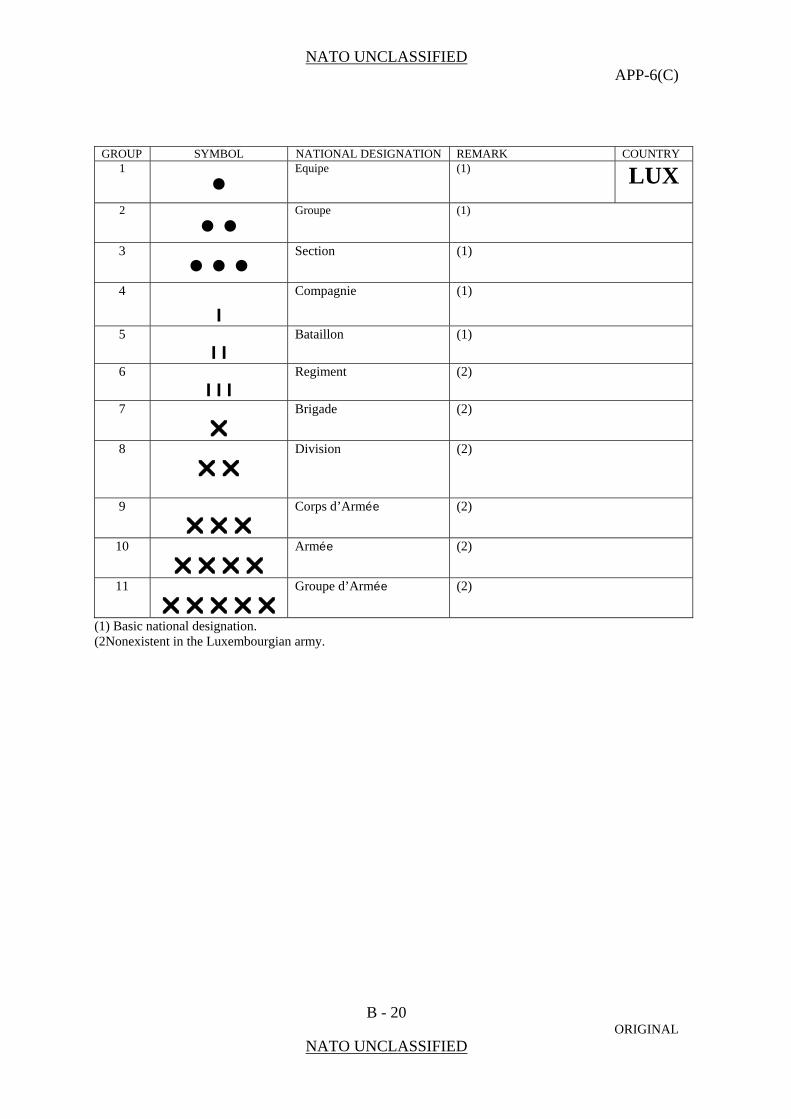
NATO UNCLASSIFIED APP-6(C)
B - 20 ORIGINAL
NATO UNCLASSIFIED
GROUP SYMBOL NATIONAL DESIGNATION REMARK COUNTRY 1
•
Equipe (1) LUX
2
• •
Groupe (1)
3 • • •
Section (1)
4
I
Compagnie (1)
5
I I Bataillon (1)
6
I I I Regiment
(2)
7
Brigade
(2)
8
Division (2)
9
Corps d’Armée (2)
10
Armée (2)
11
Groupe d’Armée (2)
(1) Basic national designation. (2Nonexistent in the Luxembourgian army.

NATO UNCLASSIFIED APP-6(C)
B - 21 ORIGINAL
NATO UNCLASSIFIED
GROUP SYMBOL NATIONAL DESIGNATION REMARK COUNTRY LVA
1 •
2 • •
3 • • •
4
I
5
I I
6
I I I
7
8
9
10
11
.
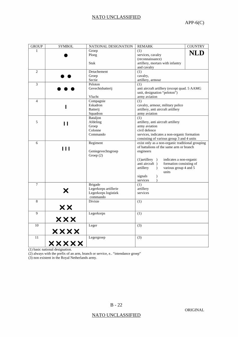
NATO UNCLASSIFIED APP-6(C)
B - 22 ORIGINAL
NATO UNCLASSIFIED
GROUP SYMBOL NATIONAL DESIGNATION REMARK COUNTRY 1
• Groep Ploeg Stuk
(1) services, cavalry (reconnaissance) artillery, mortars with infantry and cavalry
NLD
2
• • Detachement Groep Sectie
(1) cavalry, artillery, armour
3
• • • Peloton Gevechtsbatterij Vlucht
(1) anti aircraft artillery (except quad. 5 AAMG unit, designation “peloton”) army aviation
4
I Compagnie Eskadron Batterij Squadron
(1) cavalry, armour, military police artillery, anti aircraft artillery army aviation
5
I I Bataljon Afdeling Groep Colonne Commando
(1) artillery, anti aircraft artillery army aviation civil defence services, indicates a non-organic formation consisting of various group 3 and 4 units
6
I I I Regiment Geniegevechtsgroep Groep (2)
exist only as a non-organic traditional grouping of battalions of the same arm or branch engineers (1)artillery ) indicates a non-organic anti aircraft ) formation consisting of artillery ) various group 4 and 5 units signals ) services )
7
Brigade Legerkorps artillerie Legerkorps logistiek commando
(1) artillery services
8
Divisie (1)
9
Legerkorps (1)
10
Leger (3)
11
Legergroep (3)
(1) basic national designation. (2) always with the prefix of an arm, branch or service, e.. “intendance groep” (3) non existent in the Royal Netherlands army.
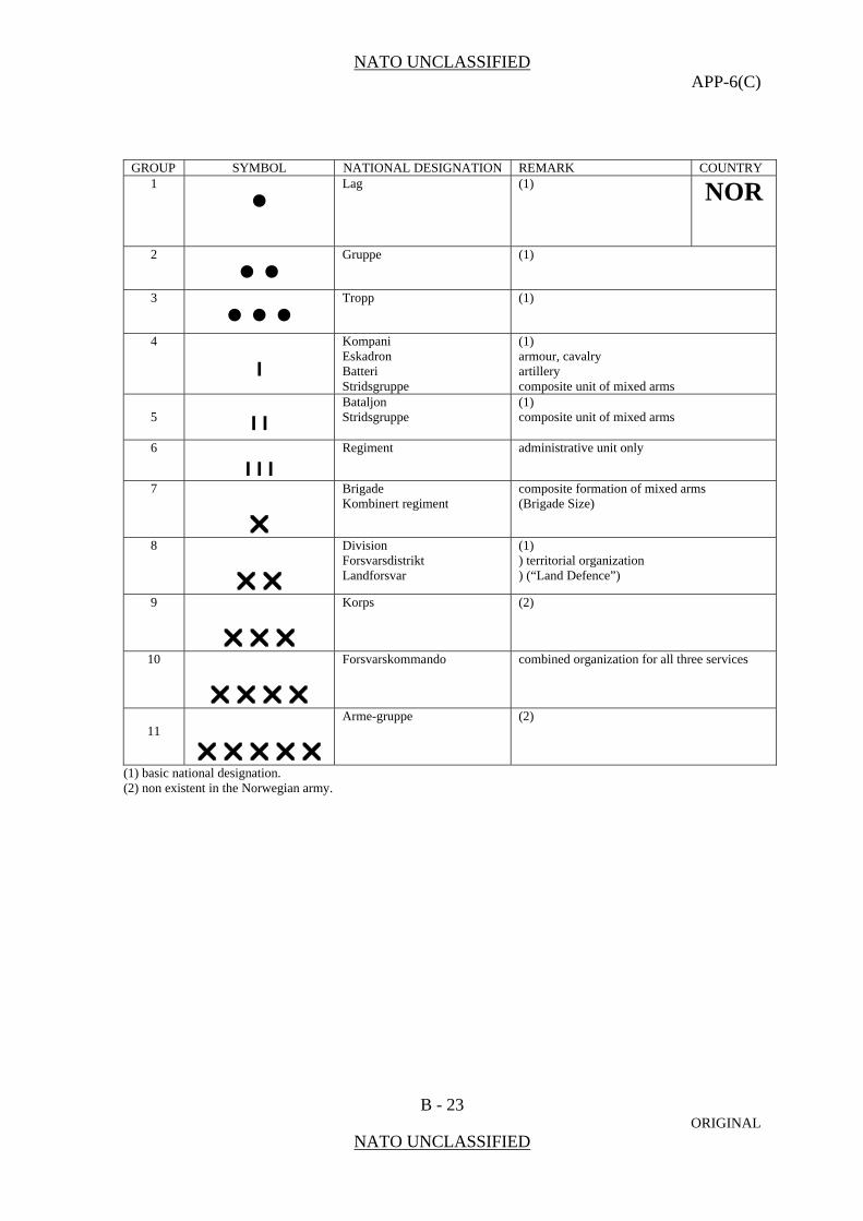
NATO UNCLASSIFIED APP-6(C)
B - 23 ORIGINAL
NATO UNCLASSIFIED
GROUP SYMBOL NATIONAL DESIGNATION REMARK COUNTRY 1
• Lag (1)
NOR
2
• • Gruppe (1)
3
• • • Tropp (1)
4
I
Kompani Eskadron Batteri Stridsgruppe
(1) armour, cavalry artillery composite unit of mixed arms
5
I I Bataljon Stridsgruppe
(1) composite unit of mixed arms
6
I I I Regiment
administrative unit only
7
Brigade Kombinert regiment
composite formation of mixed arms (Brigade Size)
8
Division Forsvarsdistrikt Landforsvar
(1) ) territorial organization ) (“Land Defence”)
9
Korps (2)
10
Forsvarskommando combined organization for all three services
11
Arme-gruppe (2)
(1) basic national designation. (2) non existent in the Norwegian army.
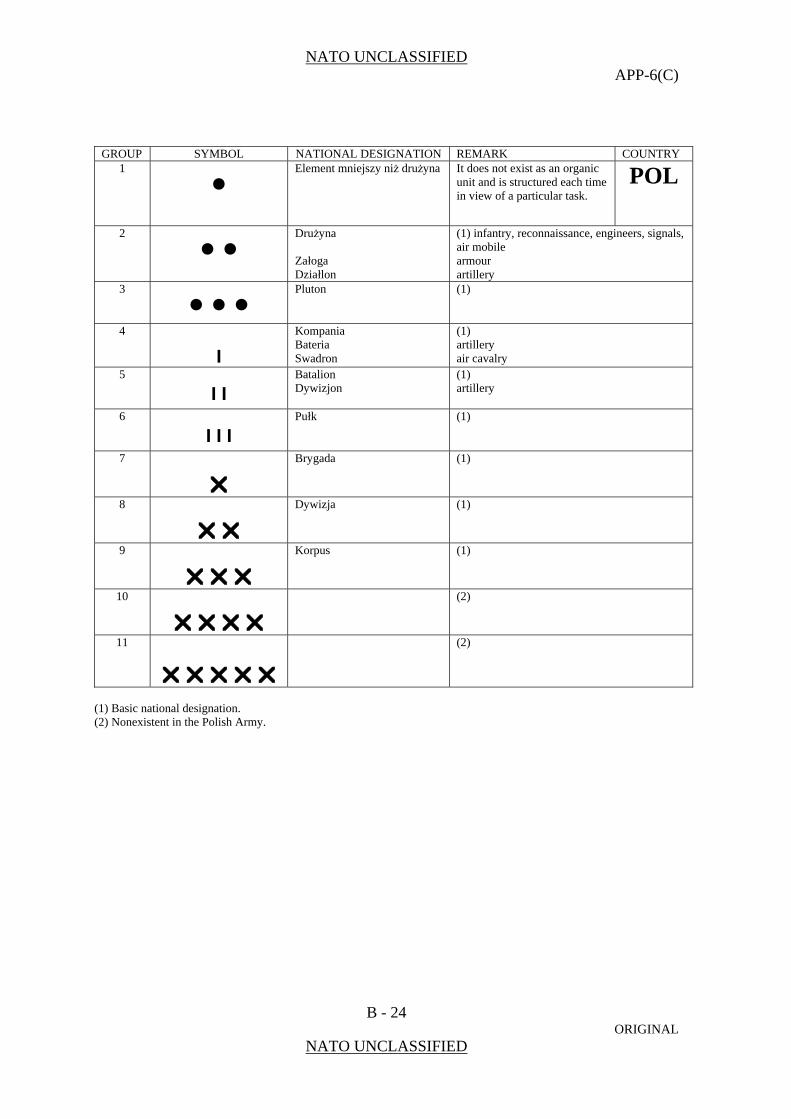
NATO UNCLASSIFIED APP-6(C)
B - 24 ORIGINAL
NATO UNCLASSIFIED
GROUP SYMBOL NATIONAL DESIGNATION REMARK COUNTRY 1
• Element mniejszy niż drużyna It does not exist as an organic
unit and is structured each time in view of a particular task.
POL
2
• • Drużyna Załoga Działlon
(1) infantry, reconnaissance, engineers, signals, air mobile armour artillery
3
• • • Pluton
(1)
4
I
Kompania Bateria Swadron
(1) artillery air cavalry
5
I I Batalion Dywizjon
(1) artillery
6
I I I Pułk
(1)
7
Brygada
(1)
8
Dywizja (1)
9
Korpus (1)
10
(2)
11
(2)
(1) Basic national designation. (2) Nonexistent in the Polish Army.

NATO UNCLASSIFIED APP-6(C)
B - 25 ORIGINAL
NATO UNCLASSIFIED
GROUP SYMBOL NATIONAL DESIGNATION REMARK COUNTRY 1
• Esquadra (1)
PRT
2
• • Seccao (1)
3
• • • Pelotao (1)
4
I
Companhia Bateria Esquadrao
(1) artillery cavalry and armour
5
I I Batalhao Grupo
(1) cavalry, armour, artillery
6
I I I Regimento
(1)
7
Brigada Agrupamento
(1) special duties organization
8
Divisao (1)
9
Corps de exército (1)
10
Exército de campanha (2)
11
Grupo de exercitos (2)
(1) basic national designation. (2) non existent in the Portuguese army.
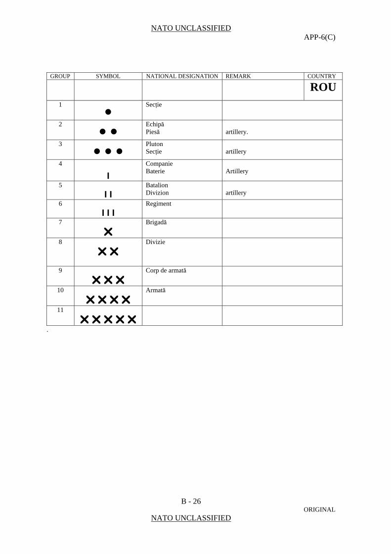
NATO UNCLASSIFIED APP-6(C)
B - 26 ORIGINAL
NATO UNCLASSIFIED
GROUP SYMBOL NATIONAL DESIGNATION REMARK COUNTRY ROU
1 •
Secţie
2 • •
Echipă Piesă
artillery.
3 • • •
Pluton Secţie
artillery
4
I
Companie Baterie
Artillery
5
I I Batalion Divizion
artillery
6
I I I Regiment
7
Brigadă
8
Divizie
9
Corp de armată
10
Armată
11
.
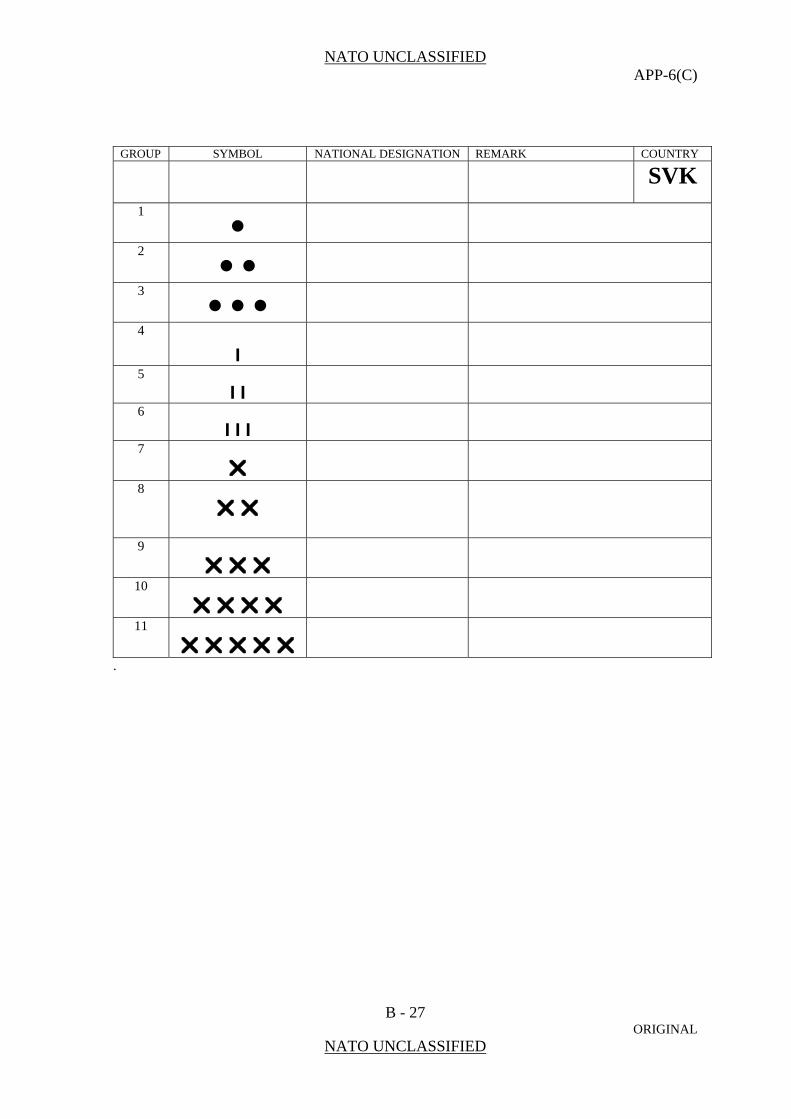
NATO UNCLASSIFIED APP-6(C)
B - 27 ORIGINAL
NATO UNCLASSIFIED
GROUP SYMBOL NATIONAL DESIGNATION REMARK COUNTRY SVK
1 •
2 • •
3 • • •
4
I
5
I I
6
I I I
7
8
9
10
11
.

NATO UNCLASSIFIED APP-6(C)
B - 28 ORIGINAL
NATO UNCLASSIFIED
GROUP SYMBOL NATIONAL DESIGNATION REMARK COUNTRY SVN
1 •
2 • •
3 • • •
4
I
5
I I
6
I I I
7
8
9
10
11
.

NATO UNCLASSIFIED APP-6(C)
B - 29 ORIGINAL
NATO UNCLASSIFIED
GROUP SYMBOL NATIONAL DESIGNATION REMARK COUNTRY 1
• Manga (1)
TUR
2
• • Kisim (1)
3
• • • Takim (1)
4
I
Bölük Batarya
(1) artillery
5
I I Tabur (1)
6
I I I Alay (muharebe grubu)
7
Tugay
(1)
8
Tümen (1)
9
Kolordu (1)
10
Ordu (1)
11
Ordular grubu
(1) basic national designation. (2) non existent in the Turkish army.

NATO UNCLASSIFIED APP-6(C)
B - 30 ORIGINAL
NATO UNCLASSIFIED
GROUP SYMBOL NATIONAL DESIGNATION REMARK COUNTRY 1
• Squad (1)
USA
2
• • Section (1)
3
• • • Platoon Detachment
(1) Special Forces, Military Police
4
I
Company Battery Troop
(1) artillery armored cavalry, air cavalry
5
I I Battalion Squadron
armored cavalry, air cavalry
6
I I I Regiment Group
(1) armored cavalry artillery, engineer, aviation, Special Forces, combat service support
7
Brigade
(1)
8
Division (1)
9
Corps (1)
10
Numbered army may be established to control two or more corps
11
Army group (1)
(1) basic national designation.

NATO UNCLASSIFIED APP-6(C)
R - 1 ORIGINAL
NATO UNCLASSIFIED
REFERENCE PUBLICATIONS
AAP-6 NATO Glossary of Terms and Definitions AAP-15 NATO Glossary of Abbreviations Used in NATO Documents and
Publications AAP-19 NATO Combat Engineer Glossary AJP-01 Allied Joint Doctrine AJP-2 Allied Joint Intelligence, Counter-Intelligence and Security Doctrine AJP-2.1 Doctrine for Intelligence Procedures AJP-3 Allied Doctrine for Joint Operations AJP-3.1 Allied Joint Maritime Operations AJP-3.2 Allied Joint Doctrine for Land Operations AJP-3.3 Joint Air and Space Operations Doctrine AJP-3.3.5 Doctrine for Joint Airspace Control AJP-3.4.1 Peace Support Operations AJP-4 Allied Joint Logistic Doctrine AJP-9 NATO Civil-Military Co-operation (CIMIC) Doctrine STANAG 1059 Letter Codes for Geographical Entities STANAG 1166 Standard Ship Designator System STANAG 1241 NATO Standard Identity Description Structure for Tactical Use STANAG 2511 Intelligence Reports STANAG 2220 Information/Intelligence Exchange on Irregular Forces STANAG 2287 Task Verbs for Use in Planning and the Dissemination of Orders STANAG 2460 Functional (Category) Codes for the Classification of Places and
Installation and Facilities STANAG 2961 Classes of Supply of NATO Land Forces

NATO UNCLASSIFIED APP-6(C)
R - 2 ORIGINAL
NATO UNCLASSIFIED
(INTENTIONALLY BLANK)
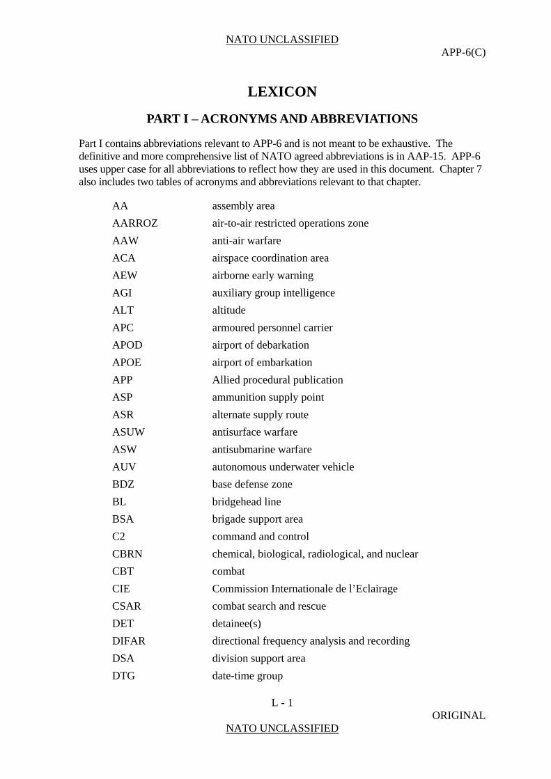
NATO UNCLASSIFIED APP-6(C)
L - 1 ORIGINAL
NATO UNCLASSIFIED
LEXICON
PART I – ACRONYMS AND ABBREVIATIONS
Part I contains abbreviations relevant to APP-6 and is not meant to be exhaustive. The definitive and more comprehensive list of NATO agreed abbreviations is in AAP-15. APP-6 uses upper case for all abbreviations to reflect how they are used in this document. Chapter 7 also includes two tables of acronyms and abbreviations relevant to that chapter.
AA assembly area
AARROZ air-to-air restricted operations zone
AAW anti-air warfare
ACA airspace coordination area
AEW airborne early warning
AGI auxiliary group intelligence
ALT altitude
APC armoured personnel carrier
APOD airport of debarkation
APOE airport of embarkation
APP Allied procedural publication
ASP ammunition supply point
ASR alternate supply route
ASUW antisurface warfare
ASW antisubmarine warfare
AUV autonomous underwater vehicle
BDZ base defense zone
BL bridgehead line
BSA brigade support area
C2 command and control
CBRN chemical, biological, radiological, and nuclear
CBT combat
CIE Commission Internationale de l’Eclairage
CSAR combat search and rescue
DET detainee(s)
DIFAR directional frequency analysis and recording
DSA division support area
DTG date-time group
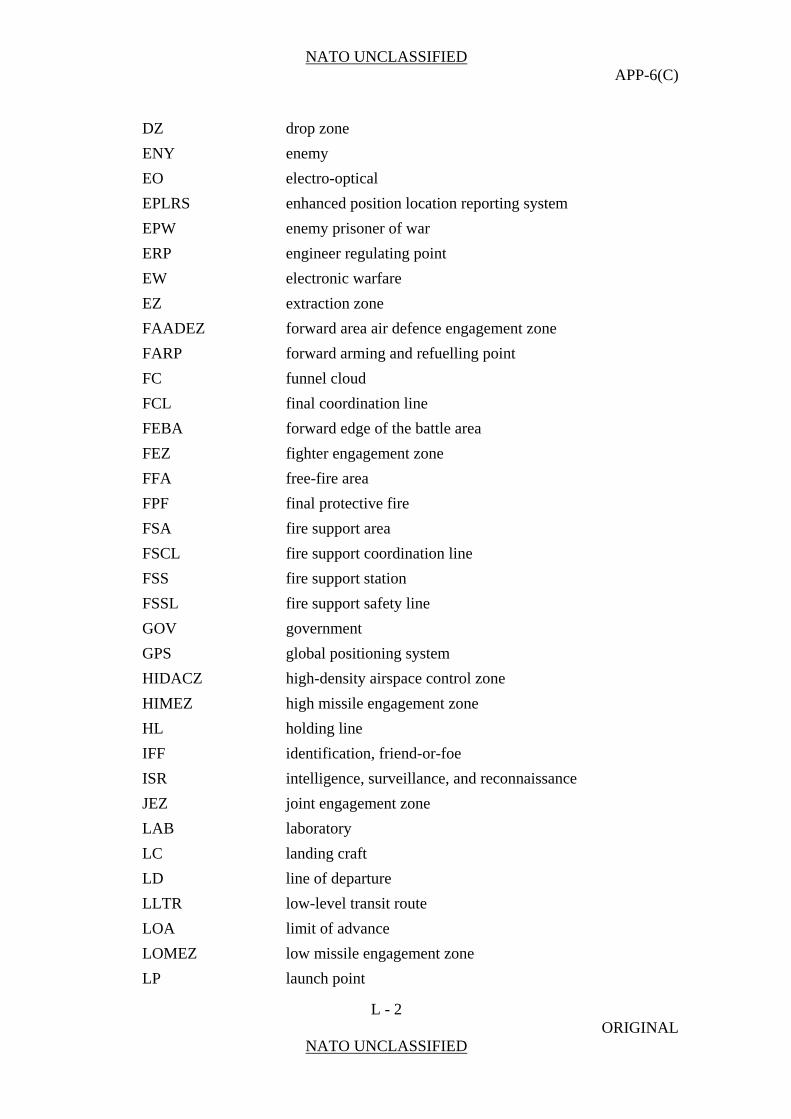
NATO UNCLASSIFIED APP-6(C)
L - 2 ORIGINAL
NATO UNCLASSIFIED
DZ drop zone
ENY enemy
EO electro-optical
EPLRS enhanced position location reporting system
EPW enemy prisoner of war
ERP engineer regulating point
EW electronic warfare
EZ extraction zone
FAADEZ forward area air defence engagement zone
FARP forward arming and refuelling point
FC funnel cloud
FCL final coordination line
FEBA forward edge of the battle area
FEZ fighter engagement zone
FFA free-fire area
FPF final protective fire
FSA fire support area
FSCL fire support coordination line
FSS fire support station
FSSL fire support safety line
GOV government
GPS global positioning system
HIDACZ high-density airspace control zone
HIMEZ high missile engagement zone
HL holding line
IFF identification, friend-or-foe
ISR intelligence, surveillance, and reconnaissance
JEZ joint engagement zone
LAB laboratory
LC landing craft
LD line of departure
LLTR low-level transit route
LOA limit of advance
LOMEZ low missile engagement zone
LP launch point
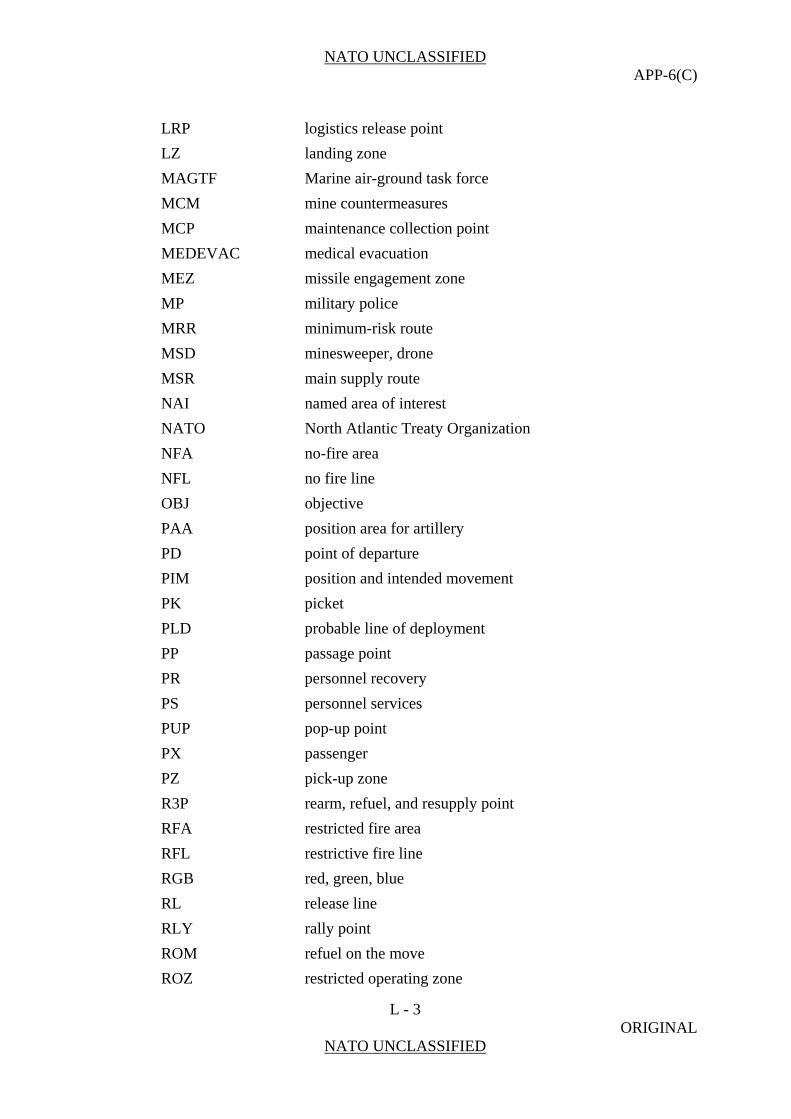
NATO UNCLASSIFIED APP-6(C)
L - 3 ORIGINAL
NATO UNCLASSIFIED
LRP logistics release point
LZ landing zone
MAGTF Marine air-ground task force
MCM mine countermeasures
MCP maintenance collection point
MEDEVAC medical evacuation
MEZ missile engagement zone
MP military police
MRR minimum-risk route
MSD minesweeper, drone
MSR main supply route
NAI named area of interest
NATO North Atlantic Treaty Organization
NFA no-fire area
NFL no fire line
OBJ objective
PAA position area for artillery
PD point of departure
PIM position and intended movement
PK picket
PLD probable line of deployment
PP passage point
PR personnel recovery
PS personnel services
PUP pop-up point
PX passenger
PZ pick-up zone
R3P rearm, refuel, and resupply point
RFA restricted fire area
RFL restrictive fire line
RGB red, green, blue
RL release line
RLY rally point
ROM refuel on the move
ROZ restricted operating zone

NATO UNCLASSIFIED APP-6(C)
L - 4 ORIGINAL
NATO UNCLASSIFIED
RS rescue surface station
RSA regimental support area
RS rescue station
RV re-entry vehicle
SAAFR standard use Army aircraft flight route
SAM surface-to-air missile
SAR search and rescue
SEAD suppression of enemy air defences
SHORADEZ short range air defence engagement zone
SIF selective identification feature
SIGINT signals intelligence
SOF special operations force
SPOD seaport of debarkation
SPOE seaport of embarkation
STANAG NATO standardization agreement
SUB submarine
TAI target area of interest
TCP traffic control post
TF task force
TGT target
TRP target reference point
TS thunderstorm
TTP trailer transfer point
TV television
UAV unmanned aerial vehicle
UL ultra light
UMCP unit maintenance collection point
UUV unmanned underwater vehicle
UXO unexploded explosive ordnance
VSTOL vertical or short take-off and landing
WEZ weapon engagement zone
WFZ weapons free zone
WMO World Meteorological Organization
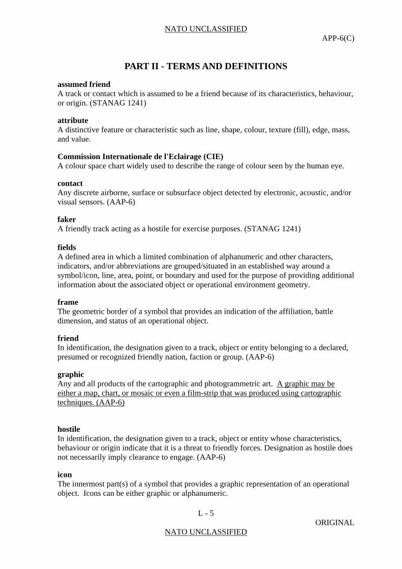
NATO UNCLASSIFIED APP-6(C)
L - 5 ORIGINAL
NATO UNCLASSIFIED
PART II - TERMS AND DEFINITIONS
assumed friend A track or contact which is assumed to be a friend because of its characteristics, behaviour, or origin. (STANAG 1241)
attribute A distinctive feature or characteristic such as line, shape, colour, texture (fill), edge, mass, and value.
Commission Internationale de l'Eclairage (CIE) A colour space chart widely used to describe the range of colour seen by the human eye.
contact Any discrete airborne, surface or subsurface object detected by electronic, acoustic, and/or visual sensors. (AAP-6)
faker A friendly track acting as a hostile for exercise purposes. (STANAG 1241) fields A defined area in which a limited combination of alphanumeric and other characters, indicators, and/or abbreviations are grouped/situated in an established way around a symbol/icon, line, area, point, or boundary and used for the purpose of providing additional information about the associated object or operational environment geometry.
frame The geometric border of a symbol that provides an indication of the affiliation, battle dimension, and status of an operational object.
friend In identification, the designation given to a track, object or entity belonging to a declared, presumed or recognized friendly nation, faction or group. (AAP-6)
graphic Any and all products of the cartographic and photogrammetric art. A graphic may be either a map, chart, or mosaic or even a film-strip that was produced using cartographic techniques. (AAP-6)
hostile In identification, the designation given to a track, object or entity whose characteristics, behaviour or origin indicate that it is a threat to friendly forces. Designation as hostile does not necessarily imply clearance to engage. (AAP-6)
icon The innermost part(s) of a symbol that provides a graphic representation of an operational object. Icons can be either graphic or alphanumeric.
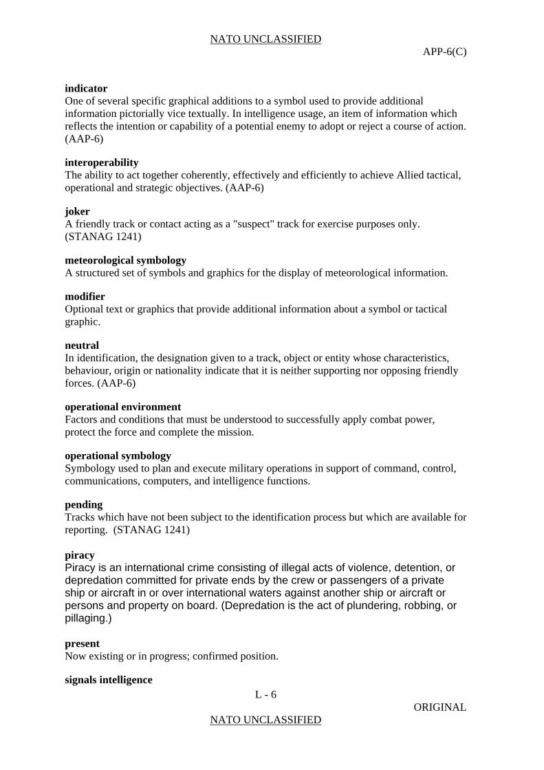
NATO UNCLASSIFIED APP-6(C)
L - 6 ORIGINAL
NATO UNCLASSIFIED
indicator One of several specific graphical additions to a symbol used to provide additional information pictorially vice textually. In intelligence usage, an item of information which reflects the intention or capability of a potential enemy to adopt or reject a course of action. (AAP-6)
interoperability The ability to act together coherently, effectively and efficiently to achieve Allied tactical, operational and strategic objectives. (AAP-6)
joker A friendly track or contact acting as a "suspect" track for exercise purposes only. (STANAG 1241)
meteorological symbology A structured set of symbols and graphics for the display of meteorological information.
modifier Optional text or graphics that provide additional information about a symbol or tactical graphic.
neutral In identification, the designation given to a track, object or entity whose characteristics, behaviour, origin or nationality indicate that it is neither supporting nor opposing friendly forces. (AAP-6)
operational environment Factors and conditions that must be understood to successfully apply combat power, protect the force and complete the mission.
operational symbology Symbology used to plan and execute military operations in support of command, control, communications, computers, and intelligence functions.
pending Tracks which have not been subject to the identification process but which are available for reporting. (STANAG 1241) piracy Piracy is an international crime consisting of illegal acts of violence, detention, or depredation committed for private ends by the crew or passengers of a private ship or aircraft in or over international waters against another ship or aircraft or persons and property on board. (Depredation is the act of plundering, robbing, or pillaging.) present Now existing or in progress; confirmed position.
signals intelligence

NATO UNCLASSIFIED APP-6(C)
L - 7 ORIGINAL
NATO UNCLASSIFIED
The generic term used to describe communications intelligence and electronic intelligence when there is no requirement to differentiate between these two types of intelligence, or to represent fusion of the two. (AAP-6) Also called SIGINT.
status A determination or declaration as to whether a track's or object's location or battlefield environment is existing/present or is planned/anticipated at the time that the symbol was generated or the time associated/presented with the symbol itself.
suspect A track or contact which is potentially hostile because of its characteristics, behaviour, origin, or nationality. (STANAG 1241)
symbol An object that presents information.
symbol identification code An alphanumeric code based on a database structure that provides the minimum elements required to construct the basic icon and/or a complete symbol.
text Words, alphanumeric information, and other American Standard Code for Information Interchange characters used to define or further designate the meaning of a symbol.
track A series of related contacts displayed on a data display console, other display devices, or a plotting board. The actual path of an aircraft above, or a ship on, the surface of the earth.
unknown 1. A code meaning information not available. 2. An unidentified target. An aircraft or ship that has not been determined to be
hostile, friendly, or neutral, using identification friend or foe and other techniques but that must be tracked by air defense or naval engagement systems. An identity applied to an evaluated track or contact which has not been identified. (STANAG 1241) In identification, the designation given to an evaluated track, object or entity that has not been identified. (AAP-6)

NATO UNCLASSIFIED APP-6(C)
L - 8 ORIGINAL
NATO UNCLASSIFIED
(INTENTIONALLY BLANK)


