APPENDICES Appendix 1 ANS-Recording Appendix 2 Simulco Oy, Reconstruction of Motion Track of m/s FINNFELLOW before Grounding on April 2, 2000 Appendix 3 The Cabling of FINNFELLOW the Compass System Appendix 4 Fault Codes of the Compass Appendix 5 Interpretation of FMEA analysis on Standard 20 compass Appendix 6 Autopilot and integrated navigation Appendix 7 Comments from Raytheon Marine GmbH Appendix 8 Comments from SAM Electronics
Transcript
APPENDICES
Appendix 1 ANS-Recording
Appendix 2 Simulco Oy, Reconstruction of Motion Track of m/s FINNFELLOW beforeGrounding on April 2, 2000
Appendix 3 The Cabling of FINNFELLOW the Compass System
Appendix 4 Fault Codes of the Compass
Appendix 5 Interpretation of FMEA analysis on Standard 20 compass
Appendix 6 Autopilot and integrated navigation
Appendix 7 Comments from Raytheon Marine GmbH
Appendix 8 Comments from SAM Electronics
APPENDIX 1
APPENDIX 2
6LPXOFR�2\
REPORT R2604001
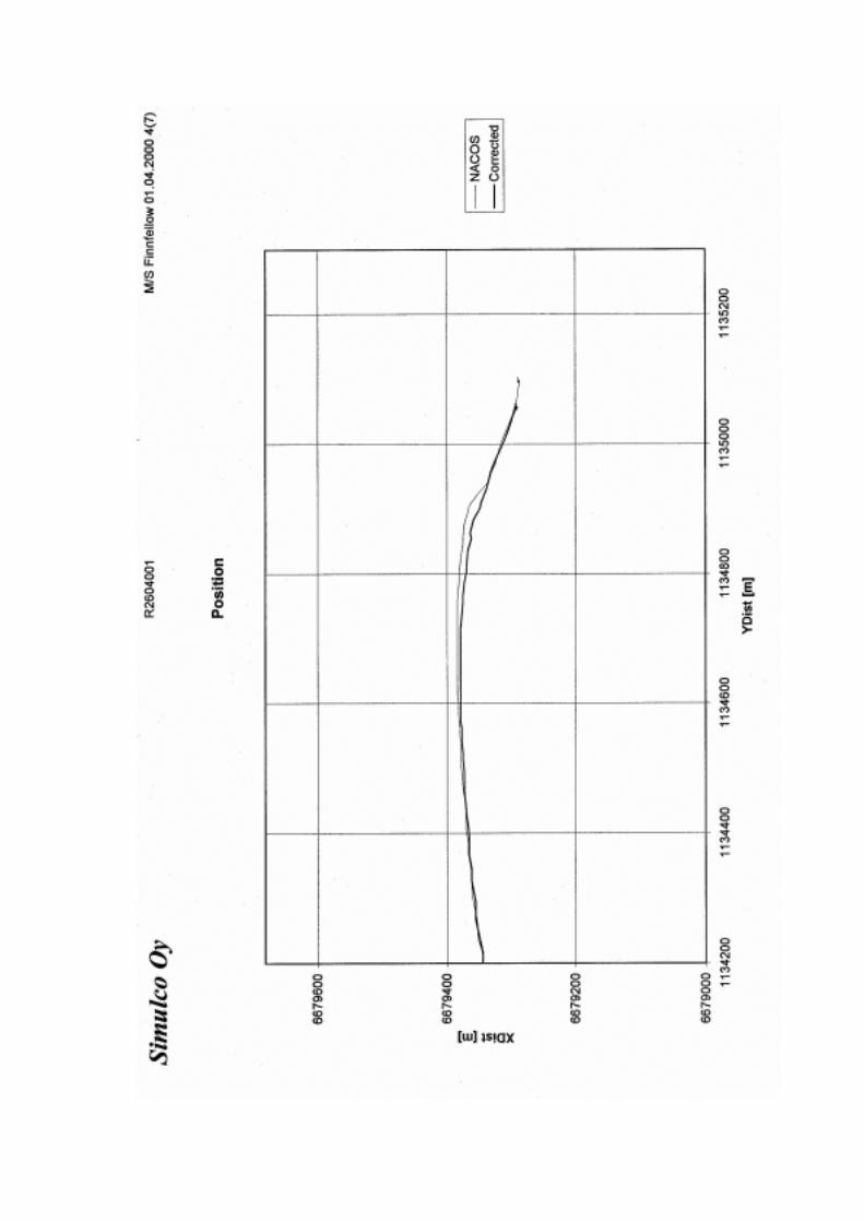
RECONSTRUCTION OF MOTION TRACK OF M/S FINNFELLOWBEFORE GROUNDING ON APRIL 2, 2000
Simulco Oy has been commissioned by the Accident Investigation Board to studyand reconstruct the probable track of M/S FINNFELLOW during the two minutesbefore she grounded on April 2, 2000.
Simulco’s simulation software for steering of a ship was used for the study. Thehydro- and aerodynamic properties of a vessel the type of the FINNFELLOW havebeen modelled in the software.
The calculations are based on the data registered by the ANS Blackbox applicationon board the ship. The registered information includes ships position, heading andspeed and course over ground. The following information received from the shippingcompany of the FINNFELLOW has been used as starting values for the study:
- The ANS Blackbox registration application was configured to collectinformation from the Ship’s Interface of the NACOS navigation system by AtlasElektronik at the time of the incident.
- The position of the vessel was measured by a DGPS receiver. Its antenna islocated 5 meters aft of midship and half a meter port of the keel line. TheDGPS-receivers position data was calculated to correspond to the location ofthe reference point in the navigation system before sending the informationthrough the Ship’s Interface. The navigation system uses the headinginformation given by the gyro-compass for this calculation. The reference pointis located on the keel line of the vessel 41.5 meters fore of midship. No otherconversions are assumed in the position calculations by the DGPS. Therefore,the position information received and registered by the ANS Blackboxapplication corresponds to the geographical location of the reference pointexcept in a situation where the heading information given by the gyro-compasswas false.
- The heading measured by the gyro-compass was recorded as such.- Course over ground was calculated in the navigation system with the help of
the course information from the receiver and the heading from the gyro-compass.As in the above, course over ground corresponds to the geographical locationof the reference point except in a situation where the heading informationgiven by the gyro-compass was false.
- Speed over ground was calculated in the navigation system directly from thelongitudinal and lateral speed components measured by the log-sensor. Themeasured values were not changed, since the sensor is located at thereference point.
The track of the midship was calculated on the basis of the information recorded bythe ANS Blackbox application (page 4) and with the help of the track, the course andspeed over ground of the midship (pages 5 and 6).
The heading during the compass malfunction was estimated with simulations. Thefollowing starting values were used in the calculations: depth of water was set at aneven 50 meters, wind heading at 350 degrees and wind speed at 9 m/s (Wind speedmeasured by the Finnish Meteorological Institute at Kumlinge weather station at00:00 on April 2, 2000). The throttle settings for the main engines were kept constant
during the simulations. Bank effects of the islands were not considered since theywere irrelevant to the case at hand.
The estimated probable heading of the vessel during the compass malfunction ispresented on page 5. The estimation is based on multiple simulations.
The corrected track is presented on page 7 together with the original recording by theANS Blackbox application. In addition, a SimBox-compatible recording database wascreated of the calculated data making it possible to revaluate the accident situation inthe ship handling simulator.
Espoo, April 26, 2000
SIMULCO OYJaakko Lehtosalo
APPENDIX 3
APPENDIX 4
Appendix 5 Interpretation of FMEA analysis on Standard 20 compass
FMEA1 (Failure Mode and Effect Analysis) is an analysis aimed at studying the operation ofequipment in a fault situation. It can also be used for testing software and searching forpossible sources of human errors. The FMEA analysis is not compulsory.
Raytheon has performed the FMEA analysis on the Standard 20 gyro compass in 19982. Thisappendix presents a summary of the analysis. The observations of the investigatorsconcerning the point in question are given in italics.
With regard to the gyro compass, the results of the FMEA comprised in the first group fivecolumns. Here is an example of columns 1-5:
No. Item/Identification Function Failure Mode and Courses Type1 - 1 Gyro Compass Equipment
STANDARD 20Gyro Compass Compass internal operating
voltages faultyI
I = Internal problem of subsystem or sensor, E = Electrical
Columns 2 and 3 remain the same for the compass. The Failure mode column presents thefaults each on its own line. The Type column indicates the fault type with one letter. In eightcases concerning the compass, the fault type is ’Internal Problem’ (I) and in two cases anelectrical fault ’Electrical’ (E).
The second group defined the effects of the fault situations above in three columns. Anexample of this is given below. When the compass does not give heading information, theFMEA handles the situation as follows in columns 6 - 8:
Failure effects
Local effects Next Higher Effects End EffectsRespective gyro compasssupplies no heading values.Heading information on coursebus invalid.
Invalid heading is distributed bycourse bus.
• Local effects columns have the same text in nine fault situations where the compassdoes not give heading information. In one situation, it is stated that the headinginformation is wrong.
• Next Higher Effects columns have the same text of the invalid heading information notbeing distributed to the auxiliaries.
• End Effects columns have been left blank. The effects of the fault on the entirenavigation system or on the safety of the ship are left unaddressed.
TMC = Transmitting Magnetic CompassR = restart system, S = repair by spare, C = repair connection.
• Failure detection method column describes the alarm message appearing on thecontrol unit. False heading information usually causes a total of ten different alarms, theHEATING alarm being one of them. The alarm message bears no indication of theaction recommendation. They represent maintenance situations.
• Compensating Provisions column carries the same text on each line. The user doesnot get the information that the system should be switched over to the other compass.
• Repair Method column recommended in all instances rebooting the system andreplacing the spare part. In one case, an additional recommendation of checking theconnection was also given. These are instructions for maintenance. The problem hasnot been considered from the point of view of the use of the compass, namely thenavigation situation.
• Remarks column was blank on each line. The conclusion of the user not being able toact correctly based on confusing and cryptic alarm messages could have been drawnhere, but the FMEA was limited to the operation of the gyro and not the effects of it.
With regard to the Control Unit of the compass system , the FMEA presented four faultsituations where false heading information is sent to the auxiliaries. One of the alarms ’NOCONNECTION’, ’NO TELEGRAMS’ and ’CU EXT.PCB.ERR’ appears on the control panel. Inthese cases the compass must be switched over to emergency mode3. The alarm’DISTRIBUT.ERR’ requires reading the heading from the magnetic compass.
Summary. It is not clear from the FMEA analyses, whether there is a sound for the alarms.The analysis gives the impression that the alarms are merely information and that the usermay interpret their meaning himself. Fourteen serious alarms of the compass system remainwithout action recommendation or sound alarm.
FMEA, as its name suggests, is an analysis, but the conclusions based on the analysis aremissing. The conclusion that in each of the fourteen fault situations the alarm message’SWITCH GYRO’ and an audio alarm should be given can be drawn from the FMEA analysis.The current alarm messages do not support the decision making of the users. The analysisdoes not protect the overall outcome of the navigation and the vessel from accidents.
3 The investigators could not find instructions for emergency use in the manual.
Appendix 6 Autopilot and integrated navigation
The development of large ro-ro passenger ferries and cargo ferries has led to the developmentof the integrated navigation systems and autopilots used in piloting. The use of an integratednavigation system arises from the needs for precise navigation and steering of vessels of thepresent size on narrow passages in the archipelago. At the same time, the steering practice inpiloting has changed. The autopilot has substituted the helmsman. This transition has takentwenty years.
The technical recommendations on autopilots were issued in 1975 and 19964 but they do nottake a stand on the use of the autopilot on the fairway or in piloting. Since the users of theequipment have not received support for their decisions from the regulations, the opinionsabout using the autopilot for steering on the fairways have split into for and against. Integratednavigation has changed the practices in piloting so that the use of autopilot in piloting isgenerally regarded acceptable.
The formation of a new practice has been slowed down by both juridical and technicallyoutdated views of the use of electronic navigation equipment as navigational aids. Thedefinition as “aid of navigation” includes the notion that the lawmaker does not take anyresponsibility of these.
The purpose of integrated navigation is to create a technical system which is not an aid but asystem that can be relied on. The manufacturer of the integrated navigation equipment shouldprovide clear requirements for the use of the equipment5.
In maritime navigation, positioning and steering have traditionally been different tasks. Theywere separated earlier both technically and hierarchically. The division of work was alsosocial. The integrated navigation system has changed navigation towards its original purposeby combining steering and positioning on the same screen. The system integrates positioning,steering and monitoring. Integrated navigation is not possible without planning of the passage,so it also promotes the realisation of the requirements of passage planning. Integratednavigation gives the greatest benefit for piloting.
The most central element in the integrated navigation system is the autopilot where combininginformation is transformed into executing the passage plan. The autopilot usually containsseveral steering modes. Manual steering is one of these, but its use means that either thepilot, the mate or the master is steering, because the effect of the steering commands relatedto the positioning must be derived from the radar screen. The helmsman cannot be employedfor the steering since this would disintegrate the positioning and steering. The navigatormakes the decisions, gives the steering commands to the autopilot or steers himself.Switching from the autopilot over to manual control must be easy. The officers of theFINNFELLOW acted according to the principles of integrated navigation.
4 Recommendation on Performance Standards for Automatic pilots. A342(IX) 1975 and
Recommendation on Performance Standards for Heading Control systems. MSC.64(67) 1996.5 For example, the manuals of STN ATLAS ELEKTRONIK contain the requirements of the equipment manufacturer on
the first page ’General Safety Precautions when using NACOS’, which give the operator clear requirements for the use.
MS “FINNFELLOW“ GROUNDING IN ALAND ON APRIL 2,2000
Dear Sirs,
Thank you very much for the report received and the opportunity provided to us to comment.
The following comments have been evaluated based on the final draft/investigation report B2/2000 M of the Finnish Accident Investigation Board (your original text in italics). We kindlypropose to consider our remarks in order to finalize the report.
Page 37:The system could not interpret the significance of the various numeric values for theofficers on watch.
For the actual situation (15 seconds after the jamming of the heading) this sentence couldbe misleading because a CMG of 85.5° could have been realistic due to other influences(Drift Angle to STB, wind from North). Therefore we propose to delete the a.m. sentencein this connection.
Page 44:The autopilot slowed down the vessel’s speed ...
We propose to substitute this sentence by: The vessel’s speed slowed down due toturning.
Page 44:The recorded position was therefore outside the assumed true contour of the ship.
We propose to add this, because it is an assumption concerning the real position of thevessel as a result of the simulation.
Page 2 of 2
Page 46:The rotation of the radar video anticlockwise was the only indication of the malfunction.
Not only the radar video indicates a malfunction, also the unexpected starboard rudder (acounter-rudder to port should be expected after a starboard turn) and the ongoing changeof the CMG to starboard at a constant heading indicated a problem.Furthermore the ship was turning to starboard although a rate of turn = 0 was indicated.
Page 57:... the heading information to the autopilot was entirely false.
We propose to replace entirely by “increasingly”.
Additional comments:
• The screen shots of the displays taken during the simulation were done with not activatedTrackpilot – this should be mentioned in the report. Therefore no deviation bars for courseand track are visible, which could have indicated a constant course error and the increasingtrack deviation during the jamming period.
• We are not sure how the simulation did influence the realistic display of the XTD (off trackdistance) to the pre-planned track, which should have been increasing considerably to “rightof the track” based on the correct position information.
In case of any further questions please do not hesitate to contact us.