32 Sediment Management Strategy 2007 The 1988 Norfolk and Suffolk Broads Act sets out the general functions of the Broads Authority in Section 2(i): It shall be the general duty of the Authority to manage the Broads for the purpose of a) Conserving and enhancing the natural beauty, wildlife and cultural heritage of the Broads; b) Promoting opportunities for the understanding and enjoyment of the special qualities of the Broads by the public; and c) Protecting the interest of navigation. In discharging its statutory duty to maintain a safe navigation, and a fundamental part of this provision is the securing of reasonable depth. Section 10 of the Act states that The Authority shall a) maintain the navigation area for the purposes of navigation to such standard as appears to it to be reasonably required; b) take such steps to improve and develop it as it thinks fit Under Section 2, Schedule 5 (1) The Authority may – a) deepen, dredge, scour or excavate any part of the navigation area; and b) sell, or otherwise dispose of as it thinks fit, any material removed from any part of the navigation area in exercise of its powers under this paragraph. Additionally, under the Port Marine Safety Code the Authority has a duty as a harbour authority to develop a Safety Management System which identifies all hazards related to marine activity and is required to carry out a risk assessment and put in place measures to reduce these risks as far as is reasonably practicable. The risk of grounding due to shallow water has been included in this assessment. These duties and powers have been exercised to date through the implementation of an annual dredging programme but a Best Value Review of Navigation identified the lack of a strategic approach, which if adopted could bring added value through working with partners towards shared objectives. Appendix 1 Extract from Broads Act
Transcript
32 Sediment Management Strategy 2007
The 1988 Norfolk and Suffolk Broads Act sets out the general functions of theBroads Authority in Section 2(i):
It shall be the general duty of the Authority to manage the Broads for thepurpose of
a) Conserving and enhancing the natural beauty, wildlife and cultural heritageof the Broads;
b) Promoting opportunities for the understanding and enjoyment of thespecial qualities of the Broads by the public; and
c) Protecting the interest of navigation.
In discharging its statutory duty to maintain a safe navigation, and afundamental part of this provision is the securing of reasonable depth. Section10 of the Act states that
The Authority shall
a) maintain the navigation area for the purposes of navigation to suchstandard as appears to it to be reasonably required;
b) take such steps to improve and develop it as it thinks fit
Under Section 2, Schedule 5 (1) The Authority may –
a) deepen, dredge, scour or excavate any part of the navigation area; and
b) sell, or otherwise dispose of as it thinks fit, any material removed from anypart of the navigation area in exercise of its powers under this paragraph.
Additionally, under the Port Marine Safety Code the Authority has a duty as aharbour authority to develop a Safety Management System which identifies allhazards related to marine activity and is required to carry out a riskassessment and put in place measures to reduce these risks as far as isreasonably practicable. The risk of grounding due to shallow water has beenincluded in this assessment.
These duties and powers have been exercised to date through theimplementation of an annual dredging programme but a Best Value Review ofNavigation identified the lack of a strategic approach, which if adopted couldbring added value through working with partners towards shared objectives.
Appendix 1 Extract from Broads Act
Sediment Management Strategy 2007 33
1. The principal purposes of the Steering Group are:
• to facilitate the development of a Sediment Management Strategy for the Broads;
• to prioritise and steer the research and practical management elements of the Sediment Management Strategy;
• to monitor and evaluate the development of the Sediment Management Strategy;
• to coordinate and channel all relevant information and expertise from the catchment, national and organisational levels through the Steering Group; and
• to informally discuss and debate sediment management issues in the Broads catchment.
2. The Partnership represents key partners (mostly public bodies) but issufficiently small to be manageable and productive. The agreed Membershipis listed below:
3. The Steering Group was responsible for overseeing the strategy which shouldbe relevant to the whole Broads catchment and its functioning. This involvesusing scientific rigour as well as practical achievability, and then subjectingmanagement scenarios to strategic planning and economic assessment. The approach is designed to improve understanding about strategic optionsand their inherent uncertainties, thereby enabling informed choices to bemade. The strategy should take into account navigation requirements,relevant directives, plans, policies and legislation.
4. The Steering Group will meet up to four times a year. Should sub-workinggroups, to deal with specific strategic issues, need to meet they will haveclear terms of reference and meet as necessary.
5. Key recommendations from the steering group and overall progress of thestrategy will be reported to the Broads Authority.
Strategy Steering GroupAppendix 2
Terms ofreference
34 Sediment Management Strategy 2007
This study has involved a review of available data relating to sediment sources inthe Broads Authority management area. Where possible, sources have beenevaluated in a semi-quantitative manner. It has been possible to make estimatesof sediment input for headwater catchments, internal catchments, riverbankerosion, sewage treatment works and industrial sources, and for sedimentoutputs from dredging activity within the Broads area. The major gaps are inquantifying organic inputs from plants and phytoplankton, tidal inputs/outputs,the related dredging carried out by Great Yarmouth Port Authority, and the role offlooding in removing sediment from the river system.
For those sources where it has been possible to make a semi-quantitativeassessment, headwater catchments and riverbank erosion are dominant.However, the implications for the future are different for these two as headwaterland use and management begins to focus on environmental protection(suggesting a potential reduction in sediment supply) whilst bank erosion is likelyto increase over the short to mid-term as setback and pile removal is used aspart of the BESL flood alleviation programme. Whilst BESL will be responsible forany additional dredging as a result of this programme it is useful to havequantification of the current system for comparison with future possibleconditions, so that their dredging responsibilities can be assessed.
A number of actions have been recommended to allow gaps in data to be filled,thus allowing a complete sediment budget for the region to be made. Much ofthis data could be collected via short-term field exercises, possibly via studentprojects. However, it will be much more valuable if the sediment budget could bemade spatially explicit, so that sources can be directly related to sedimentationand dredging requirements. This will need organisation of current data andcollection of additional data to infill gaps. In support of this it is recommendedthat the Broads Authority develop a database of sediment related information anda sediment GIS to put information into a spatial context.
Whilst this report has focussed on identification and a preliminary quantification ofsediment sources to the Broads management area, it must be remembered thatsediment fits into a much wider decision making process. Catchment widemanagement proposals need to consider many aspects other than sediment, eg conservation, navigation, public enjoyment, costs, interactions with otherauthorities. The Broads Authority operates within a defined set of objectives – the duties to provide public enjoyment, navigation and conservation. Clearly anyactions need to work within the law and within budgets. The Broads Authorityhas restricted control over some processes and therefore its actions in thesecases will be limited to influence and persuasion. This is likely to be morepowerful if backed up by at least semi-quantitative evidence. Furthermore it isunclear how the implementation of emerging European directives and nationalpolicy will affect the prioritisation of Broads objectives and management optionsin the future.
All recommended actions and sediment sources are evaluated within amanagement context in the report, in order that any programmes initiated as aresult of this study support management decisions rather than purely scientificinterest. It is of course to be recommended that where science funding isavailable this is also sought to enhance actions taken by the Broads Authority.
Appendix 3 Executive summary of desk based study
Desk based study of the sediment inputs tothe Broads catchment,with the identification of key inputs andrecommendations forfurther targetedresearch andmanagement tominimise inputs,Cranfield University,Silsoe
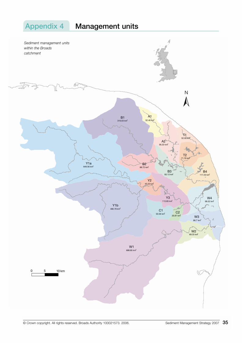
Sediment management unitswithin the Broadscatchment
Appendix 4
36 Sediment Management Strategy 2007
Hydrographic survey dataAppendix 5
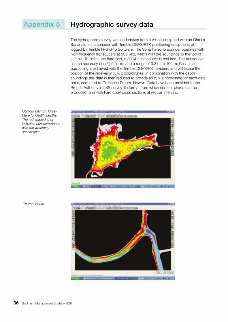
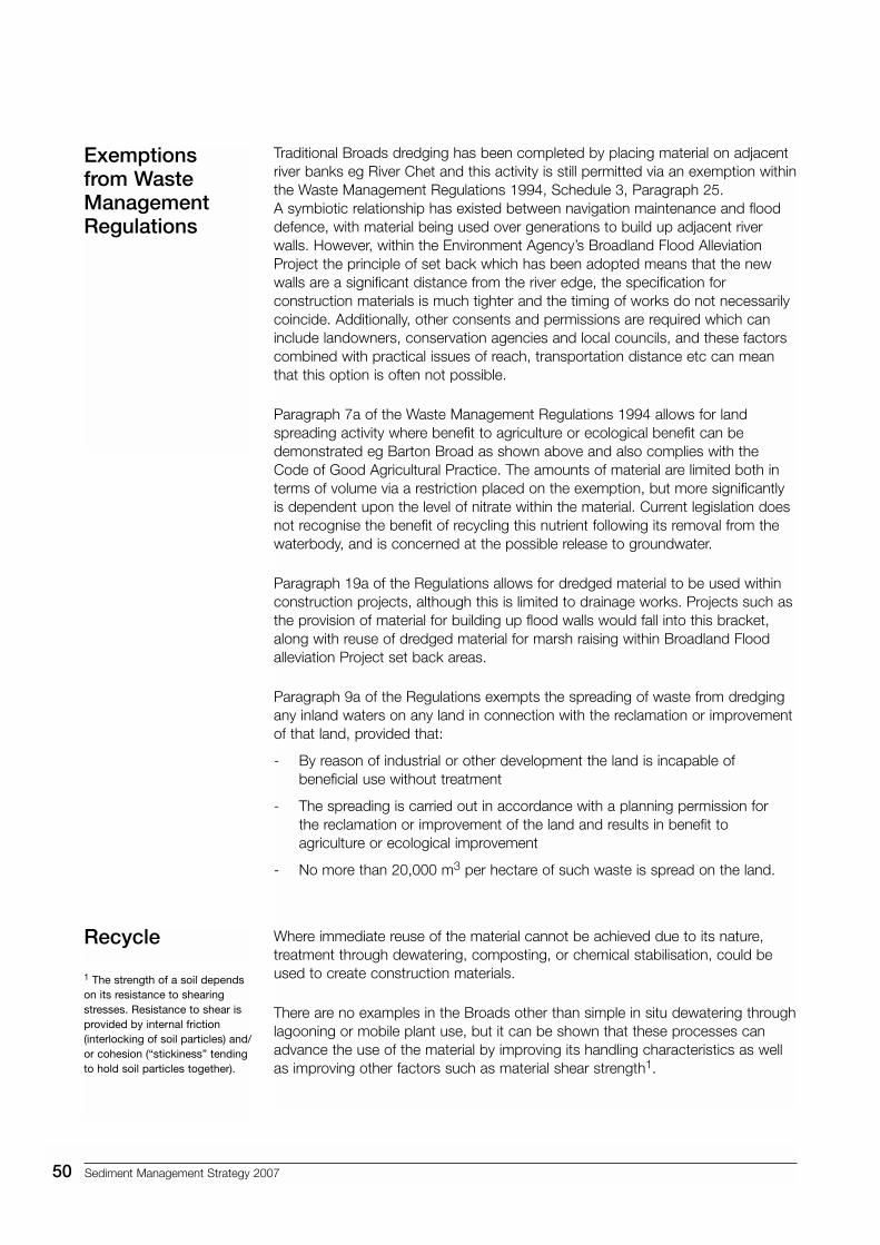
The hydrographic survey was undertaken from a vessel equipped with an OhmexSonarLite echo sounder with Trimble DGPS/RTK positioning equipment, alllogged by Trimble HydroPro Software. The Sonarlite echo sounder operates withhigh frequency transducers at 235 Khz, which will take soundings to the top ofsoft silt. To define the hard bed, a 30 Khz transducer is required. The transducerhas an accuracy of (+/-) 0.01 m, and a range of 0.3 m to 100 m. Real timepositioning is achieved with the Trimble DGPS/RKT system, and will locate theposition of the receiver in x, y, z coordinates. In combination with the depthsoundings this data is then reduced to provide an x, y, z coordinate for each datapoint, corrected to Ordnance Datum, Newlyn. Data have been provided to theBroads Authority in LSS survey file format from which contour charts can beproduced, and with hard copy cross sections at regular intervals.
Contour plan of HorseyMere to identify depths. The red shaded areaindicates non-compliancewith the waterwayspecification.
Thurne Mouth
Sediment Management Strategy 2007 37
The development of the ideal navigable envelope cross section profile wasachieved after considering the following points:
• Depth established by waterway specifications.
• The width of the channel at the agreed depth has been established at 2/3 theoverall width. This profile allows dredged volume to be minimised as well asrecognising the need for a sufficient width for all types of boating activity.
• The 1:3 side slopes allow a stable profile for the further encouragement oflittoral vegetation, and are appropriate for the nature of bed material, where a steeper slope is likely to result in slumping.
The adopted profile recognises the design of recent flood defence works, throughthe Broadland Flood Alleviation Project, and establishes a benchmark. It is anticipated that through the removal of hard defences, the rivers will likelybecome mobile, and this approach will allow meanders to develop. Interventionwill then only be required where the envelope is compromised and theEnvironment Agency or its contractors will carry out any required channelreinstatement.
Various site-specific profiles shown overleaf have also been developed for eachmanagement unit following analysis of the hydrographic survey data. However, it should be noted that for narrower piled river sections the adopted envelopereflects these existing conditions, to protect the navigable width from futuredevelopments. Likewise, specifications will be amended alongside BroadsAuthority moorings to ensure adequate depth alongside the quayheading.
Navigable envelope cross sectionsAppendix 6
38 Sediment Management Strategy 2007
Burgh St Peter to St Olaves – Area W3
St Olaves to Breydon Water – Area W4
1 m Margin
1 m Margin1 m Margin
1 m Margin
Minimum 66% channel width
-1.8 m depth @ Mean low water
-2.0 m depth @ Mean low water
Minimum 66% channel width
Slope of 1:3
Slope of 1:3
Bargate Dykes – Area Y2Rockland Dykes – Area Y3
Ideal 3 m Margin(varies)
Ideal 3 m Margin(varies)
Depth below average water varies according to waterway specifications
Minimum 66% channel widthSlope of 1:3
Slope of 1:3Minimum 60% channel width
1 m Margin1 m Margin
Horstead to Wroxham – Area B2
-2.0 m depth @ Mean low water
-1.5 m depth @ Mean low water
Average width 39 m
Average width 37 m
Average minimum 26 m
Average minimum 25 m
Average width Y2 15 m – Y3 14 m
Average minimum 17 m
Average minimum Y2 10 m – Y3 9 m
User waterway specifications (not to scale)
Sediment Management Strategy 2007 39
Wroxham to Acle – Area B3
2 m Margin
-1.8 m depth @ Mean low water
2 m Margin
-2.0 m depth @ Mean low water
Minimum 60% channel widthSlope of 1:3
Downstream of Acle – Area B4
1 m Margin1 m Margin
-2.0 m depth @ Mean low water
Minimum 60% channel widthSlope of 1:2
Slope of 1:2 Minimum 60% channel width
Downstream of Barton Broad to Ant Mouth – Area A2
No MarginNo Margin
Brograve Mill to Thurne Mouth – Area T2
3 m Margin3 m Margin
-1.5 m depth @ Mean low water
Minimum 60% channel widthSlope of 1:3
Average width 40 m
Average minimum 26 m
Average width 36 m
Average minimum 24 m
Average width 21 m
Average minimum 14 m
Average width 26 m
Average minimum 17 m
User waterway specifications (not to scale)
40 Sediment Management Strategy 2007
Minimum 66% channel width
-2.0 m depth @ Mean low water
New Mills to Brundall – Area Y2
Brundall to Cantley – Area Y3
Loddon to River Yare – Area C2
Geldeston Boat Dyke – Area W2
Slope of 1:3
Slope of 1:2
Slope of 1:2
Slope of 1:3
Minimum 66% channel width
Minimum 66% channel width
Minimum 66% channel width
Geldeston to Burgh St Peter – Area W2
3 m Margin 3 m Margin
No MarginNo Margin
-1.5 m depth @ Mean low water
-2.0 m depth @ Mean low water
1 m Margin1 m Margin
Oulton Dyke to Oulton Broad – Area W3
3 m Margin3 m Margin
-1.8 m depth @ Mean low water
Average width Y2 54 m – Y3 56 m
Average minimum Y2 35 m – Y3 37 m
Average width C2 14 m – W2 14 m
Average minimum 9 m
Average width 34 m
Average minimum 22 m
Average width 37 m
Average minimum 24 m
User waterway specifications (not to scale)
Sediment Management Strategy 2007 41
1 m
Mar
gin
1 m
Mar
gin
Ree
dha
m t
o B
reyd
on W
ater
and
Bre
ydon
Mai
n C
hann
el –
Are
a W
4
-4.0
m d
epth
@ M
ean
low
wat
er
Min
imum
33%
cha
nnel
wid
thA
vera
ge 1
7 m
@ 4
m
33
m @
2m
Slo
pe o
f 1:3
Min
imum
33%
cha
nnel
wid
th A
vera
ge 1
8 m
Min
imum
66%
cha
nnel
wid
th A
vera
ge 3
7 m
Slo
pe o
f 1:3
-4.0
m d
epth
@ M
ean
low
wat
er-2
.0 m
dep
th @
MLW
Slo
pe o
f 1:3
3 m
Mar
gin
3 m
Mar
gin
3 m
She
lf3
m S
helf
Can
tley
to R
eed
ham
– A
rea
Y3
Had
dis
coe
Cut
– A
rea
W4
Pro
fix M
attin
g
-1.0
m A
OD
17.0
m M
inim
um
Mea
n lo
w w
ater
-0.
1 m
Abo
ve O
rdna
nce
Dat
um (A
OD
)
-2.
10 m
AO
D -
1.64
m A
OD
0.8
m A
OD
Gab
ion
Cha
nnel
mar
ker
post
Cha
nnel
mar
ker
post
14.5
m M
inim
um
Slo
pe o
f 1:3
-2.0
m d
epth
@ M
ean
low
wat
er
Use
r w
ater
way
sp
ecifi
catio
ns (n
ot t
o sc
ale)
42 Sediment Management Strategy 2007
Drivers Pressures
PressuresParticle input/transport sedimentation resuspension bank erosion flood plain/bank depositionFloodingNutrient/contaminant inputs/transport
Socio-economicNavigabilityLand use classBoating numbers
EnvironmentalEcosystem function loss of habitat loss of funcrtion biotype shiftHydrological change in flow shallowing loss in depthLack of Good Environmental Potential
Socio-economicDredging/ disposal costsWater treatment costsNon-complianceLoss of navigabilityAesthetic loss
Within the desk based study headwaters were considered as a separatemanagement unit. In themselves, each upriver area is subject to diffuse pollutionfrom agricultural sources, bank erosion and other inputs. However, at theboundary with the Broads area they enter the system as a point source and socould be tackled in alternative ways.
The Environment Agency with DEFRA and Natural England, is currentlycompleting a Pilot Study in the Wensum Valley, working with farmers andagronomists to improve land management methods to reduce diffuse pollutionwithin the sub catchment, and this should eventually result in a reduced inputthrough the New Mills sluice at the head of navigation on the River Wensum aswell as improving the water quality within the upriver SSSI. Higher Level Schemespromoted by Natural England also encourage better soil management to farmerswithin the Broads and wider catchment areas, although the take up cannot betargeted or guaranteed.
Alternatively, silt traps could be established upriver of the sluice, which, if regularlycleaned out could also reduce the amount of sediment coming through thesluice.
Management control techniques
Headwaters
New Mills sluice
Bank erosion
Martham bank restoration
Source controltechniques
Bro
ads
Aut
horit
yM
ike
Pag
e
44 Sediment Management Strategy 2007
There are a number of techniques to tackle bank erosion, both locally andstrategically.
1. Erosion protection works
a. These are set out in detail within the Waterway Bank Protection ReferenceManual (Environment Agency 1999), along with a methodology for selectingthe appropriate technique for any given situation.
b. Flood defence works currently undertaken by Broadland EnvironmentalServices Ltd on behalf of the Environment Agency involve removing harddefences to promote a more natural and sustainable riverbank edge. Worksto agree the monitoring methodology and trigger levels for remedial worksare currently in progress, and the risk of accelerated erosion in the short termhas been recognised within a Memorandum of Understanding with theBroads Authority.
2. Vegetation management
Scrub clearance andpromotion of reed growthare effective in providingnatural banks, which havethe ability to absorb anddissipate wave energythus reducing erosiveforces.
3. Boat control measures
a. Numbers – the Broads Authority currently has no power to limit the numbersof boats registered within the area. Using the Boat Census data it is possibleto recognise that whilst numbers remain stable there is a change in thecomposition of the fleet which is reflected by the declining trend of boatmovements since the 1980’s, primarily due to the declining hire boat industry.
b. Speed – Speed Limit byelaws were introduced in 1992 and the Authorityemploys Navigation Rangers to patrol the rivers to provide advice andassistance, as well as enforce all navigation byelaws. Speed Limit compliance
monitoring recentlycarried out showed a high incidence of vesselsexceeding the speed limitalthough the majority wasexceeding by less than 1 mph. Further measurescould includerequirements for speedindicators to be providedon board vessels toimprove boaters’ ability to
Scrub clearance
Navigation ranger usingradar gun
Bro
ads
Aut
horit
yB
road
s A
utho
rity
Sediment Management Strategy 2007 45
control the vessel, a greater level of patrolling, more speed limit signs, andwell publicised enforcement action/prosecutions. Work is ongoing lookinginto the effectiveness of each of these techniques, to improve futuremanagement.
c. Wash – boat wash could also be reduced through hull design and theAuthority is working with the Anglia Boatbuilders Association through grantaid and technical support on the development of an Ecoboat, to be used inpromotion of sustainable boating.
4. Wave action
It is not possible to reduce tide or weather generated waves/erosive forces,but by promoting reed growth as stated above this energy could bedissipated.
There are a number of point sources identified within the Broads area, eg InternalDrainage Boards outfalls, Sewage Treatment Works (STWs) outfalls, highwaydrain outfalls. These could be tackled physically through silt traps. Imposingconditions regarding level of suspended solids within discharge consents givenby the Environment Agency can only be applied to STWs.
The amount of siltation within the Broads attributable to organic material iscurrently unquantified but could include:
1. Algal deposit – water quality improvements within the system will hopefullyeventually lead to a reduction of algae within the water column.
2. Leaf matter – Tree and scrub clearance on riverbanks and ronds will reducethis input, although some areas of vegetation will be preserved as identified inthe Tree and Scrub Guidance document, to maintain a mosaic of habitats.Overhanging trees that create a hazard to navigation will be managed.
3. Aquatic plants – Material produced through the die back of aquatic plantsmay be a local issue, but it is believed that where these exist there is acorresponding decrease in algae which have a very rapid turnover thus thecomparative volume is lower.
Point sources
Organic material
Boat travelling with minimalwash
Pet
er H
owe
46 Sediment Management Strategy 2007
In situtreatments
Again, this element of source is unquantified but is believed to be a limited issue,confined to lower reaches only. There are no control measures or techniques thatcould reduce marine inputs other than physical barriers but that would be adisproportionate response to a minor input.
Whilst there continues to be a high level of material already within the systemresuspension can provide a recycling of sediment within the system. This couldmean sediment moving from areas where it does not pose or create difficultiesinto more sensitive areas, possibly only moving under storm or flooding eventswhere the energy within the channel is greater than usual. Control measurescould include:
• Bed stabilisation by vegetation growth, where plant roots could assist to bindsediments. This can only be achieved where water quality is good, and thelevel of disturbance is likely to be low, eg within biomanipulation barriers orclosed water bodies.
• Deepening to increase under keel clearance by dredging or in-channeltechniques would reduce the likelihood of bed disturbance by prop wash inshallow reaches. However, if navigation passage is not impeded by waterdepth it could be considered that dispersion of the disturbed sediment byvessels may be more sustainable than dredging intervention.
In-channel techniques exist which can be applied at sediment receptor sites(areas of accumulation) to relocate sediment within the water environment. These include:
(i) Water injection dredging – low-pressure water is introduced to the surfacesediments in order to create a density plume, which will flow under forces of gravity, tidal flow and differential pressure into low areas. The area ofdispersion will depend upon particle size but has been widely used by ports and harbours where the disturbed sediments could not besubsequently identified.
(ii) Ploughing – this is a more controlled technique where material is movedphysically by dragging the plough from shallow to deeper areas, either fordeposit or natural dispersion by tidal or scouring action.
(iii) Agitation dredging – bed material is disturbed by blades/chains to putsediment into suspension throughout the water column and again dispersionis achieved by tidal flows.
These techniques have the additional benefit that they do not require disposal of material arising from the works, and so can be a cost effective means ofdelivering increased water depth.
Marine input
Resuspension
Sediment Management Strategy 2007 47
Dredgingtechniques
The traditional dredging technique used within the Broads for the last 40 years,grab dredging uses a clam shell bucket suspended from a crane jib and is usuallyoperated by wires to dig material from the bed of the waterbody eg River Yare,shown above.
Due to the difficulty of bank side access the dredger is usually water borne, andtowed into position by a tug. This method is relatively controlled, works within aconfined area and removes sediment from the water environment. The jib isusually sufficient length to place material ashore if allowed, but otherwise is usedin combination with barges to transport the spoil to an agreed disposal site.Disturbance of the sediments can create an increase in suspended solids withinthe water column locally, although this is relatively low. A more significant sourceof sediment to the water column can arise from spillages from the bucket, eitherfrom over filling, poor seals or premature opening. The clam shell bucket can alsoresult in an uneven bed profile, with ‘bites’ being seen when examined by divers.
In order to try and reduce therisk of spillage of dredgingspoil, works have beenundertaken to trial hydraulicbackacters which are used byother inland waterways andconsidered by the CIRIAdocument ‘Inland Dredging -guidance on good practice’report 169, to produce lowlevels of suspended sediment.
Our experience demonstrated that the level of operator skill is a prime factor inthe control of spillage, for example an open bucket slewing at an inappropriatespeed could cause spillage. Additionally, a smoother channel profile could beachieved, eg Catfield Dyke approach channel. Unless using a long reachexcavator, there is a reduced ability to place material directly to the bank side, so the plant must be supported by barges.
Grab
Grab dredging at Five Milebends River Yare
Hydraulicexcavator
R N
Flo
wer
s
Bro
ads
Aut
horit
y
48 Sediment Management Strategy 2007
Cutter suction dredging can be used within the Broads, and uses an auger todisturb the sediments, which is then sucked into a pump and can be transportedsignificant distances. This technique is most controllable, does not producesuspended solids at the point of use and provides a very smooth bed profile.
However, to transport the sediments high volumes of water are also taken upthrough the pump, with a low percentage of solids (usually 10%). The resultantmaterial requires dewatering and probably requires construction of lagoons tomanage the process. The excess water can be returned to the waterbody, butsuspended solids need to be settled out first to ensure no local pollution at thedischarge point. The material may take significant time to dry sufficiently to berehandled and the area reinstated.
In order to increase the opportunities for beneficial reuse of dredged material trialshave been undertaken using a concrete pump, which can transport materialswithout the need for adding water. This means that materials produced throughtraditional dredging techniques can be transported to an appropriate site andoffloaded from the barge and placed over a greater area using a pipe. Thisdecreases the disturbance otherwise incurred using dumpers or other heavyearth moving equipment, which may also be restricted due to the marshy groundconditions eg St Benet’s.
Suction dredging
Combined digand pump
Suction dredger - as usedat Barton Broad
Sediment lagoons -constructed to receivepumped silt and clean thereturn water
Dredgings from ThurneMouth offloaded from barge and pumped over St Benet’s site
Land
& W
ater
Ser
vice
sM
ike
Pag
e
Sediment Management Strategy 2007 49
As discussed in the Sediment Management Strategy, before reviewing thefollowing methods for disposal, subject to the sediment quality, any dredgingproject should first consider mechanisms to reduce or minimise material arisingfrom the dredging by considering the specification for works.
Where at all possible projects should aim for beneficial reuse of the dredgedmaterial. When designing the project initially sediment quality from the sedimentcharacterisation survey database should be reviewed and a site specific samplingsurvey should be completed if required to help refine possible options, which willbe limited by contamination levels, particle size, organic content etc.
Possible options include:
• Habitat creation eg Bure Loop salt marsh creation, where dredged materialwas used behind a rock toe to build up a sub tidal mud flat outside thenavigation area to develop a salt marsh community.
• Land spreading for agricultural benefit eg Barton Broad lagoons.
• Flood defence works, eg marsh raising in set back areas to create newreeded ronds such as Seven Mile House. Dredgings can also be used toprovide backfill to erosion protection measures such as alder pole piling,gabions, or within geobags. Additionally, direct crest raising has been carriedout where treatment using mobile plant has been trialled to blend dredgingswith other materials eg Land & Water trial at Cantley sugar beet factory,where the resulting material was used within the Langley marshes flood wall.
• Land raising, where low-lying land requires works to improve the amenity ofthe site. In the case of St Benet’s Abbey shown above and below, the workswere required to help stabilise the adjacent historic remains of a ScheduledAncient Monument.
The best management projects are those which can deliver multiple benefits eg Bure Loop, St Benet’s Abbey, working with partners to ensure added value isachieved in all stages of the project and promoting all of the Broads Authority’sstatutory duties.
Disposal ofdredgings
Beneficial reuse
Land raising at St Benet’sAbbey
Land
& W
ater
Ser
vice
s
50 Sediment Management Strategy 2007
Traditional Broads dredging has been completed by placing material on adjacentriver banks eg River Chet and this activity is still permitted via an exemption withinthe Waste Management Regulations 1994, Schedule 3, Paragraph 25. A symbiotic relationship has existed between navigation maintenance and flooddefence, with material being used over generations to build up adjacent riverwalls. However, within the Environment Agency’s Broadland Flood AlleviationProject the principle of set back which has been adopted means that the newwalls are a significant distance from the river edge, the specification forconstruction materials is much tighter and the timing of works do not necessarilycoincide. Additionally, other consents and permissions are required which caninclude landowners, conservation agencies and local councils, and these factorscombined with practical issues of reach, transportation distance etc can meanthat this option is often not possible.
Paragraph 7a of the Waste Management Regulations 1994 allows for landspreading activity where benefit to agriculture or ecological benefit can bedemonstrated eg Barton Broad as shown above and also complies with theCode of Good Agricultural Practice. The amounts of material are limited both interms of volume via a restriction placed on the exemption, but more significantlyis dependent upon the level of nitrate within the material. Current legislation doesnot recognise the benefit of recycling this nutrient following its removal from thewaterbody, and is concerned at the possible release to groundwater.
Paragraph 19a of the Regulations allows for dredged material to be used withinconstruction projects, although this is limited to drainage works. Projects such asthe provision of material for building up flood walls would fall into this bracket,along with reuse of dredged material for marsh raising within Broadland Floodalleviation Project set back areas.
Paragraph 9a of the Regulations exempts the spreading of waste from dredgingany inland waters on any land in connection with the reclamation or improvementof that land, provided that:
- By reason of industrial or other development the land is incapable ofbeneficial use without treatment
- The spreading is carried out in accordance with a planning permission for the reclamation or improvement of the land and results in benefit toagriculture or ecological improvement
- No more than 20,000 m3 per hectare of such waste is spread on the land.
Where immediate reuse of the material cannot be achieved due to its nature,treatment through dewatering, composting, or chemical stabilisation, could beused to create construction materials.
There are no examples in the Broads other than simple in situ dewatering throughlagooning or mobile plant use, but it can be shown that these processes canadvance the use of the material by improving its handling characteristics as wellas improving other factors such as material shear strength1.
Exemptions from WasteManagementRegulations
Recycle
1 The strength of a soil dependson its resistance to shearingstresses. Resistance to shear isprovided by internal friction(interlocking of soil particles) and/or cohesion (“stickiness” tendingto hold soil particles together).
Sediment Management Strategy 2007 51
Experiences reported from Belgium have identified that whilst there has been abig push for reuse and recycling of dredged material there are significantdifficulties including low customer confidence, variable supply, limited market etc,therefore they have achieved a very limited success.
The Broads Authority has a single licensed site, at Postwick Tip. This site hadbeen in use for many years, to receive dredgings form the urban areas ofNorwich and suburbs but subsequent to the Waste Management Regulations thelicence was suspended pending a Regulation 15 risk assessment needed todetermine risk to groundwater. The site was reopened in 2001 and is licensed toreceive lightly mercury/copper contaminated materials which can be found withinan 18 km stretch of the Rivers Wensum and Yare. Due to the limited capacity ofthe site disposal of uncontaminated waste is discouraged, to preserve theavailability to deal with material which would otherwise have to go to commerciallandfill.
There has previously been a network of historic sites around the Broads, usuallyadjacent to open waterbodies, which have been used to receive dredgedmaterial. Due to changes in waste legislation and site designations, all of thesesites are now closed, and will require some level of restoration.
A strategic network of new sites will likely be required to be developed, which willhave to have waste management licences, although it has been agreed thatthese sites will fall outside the scope of the Landfill Directive and as such will notrequire a Pollution Prevention Control permit.