125
Appendix 2 Instruction Manual
Appendix 2
Instruction Manual

1 JICA STUDY TEAM SENCICO PÁG.
INSTRUCTOR MANUAL
COURSE
AWARENESS – RAISING CONCERNING SAFER HOUSING
AGAINST EARTHQUAKE
INSTRUCTOR MANUAL
4-1-A2-1

2 JICA STUDY TEAM SENCICO PÁG.
INSTRUCTOR MANUAL
This manual has been prepared by JICA STUDY TEAM and SENCICO with the technical and financial cooperation of the Government of Japan
TEAM JOB JICA STUDY TEAM
Ichiro Kobayashi Kyoichi Sugiyama Takatsugu Shimada Gustavo Quijada Miguel Alemán
SENCICO – ICA
Ing. Juan Cajachagua Castillo Gerente Zonal de Sencico
Econ. Juan López Arias. Especialista Educativo
Ing. Carlos Condorchoa C. Promotor Educativo
Inst. Marco A. Condorchoa Capacitador
4-1-A2-2

3 TEMA: CONVENIO SENCICO - JICA AGOSTO DE 2,008 PÁG.
INSTRUCTOR MANUAL
1. FUNCTIONS DEFINITION
4-1-A2-3
4 TEMA: CONVENIO SENCICO - JICA AGOSTO DE 2,008 PÁG.
INSTRUCTOR MANUAL
4-1-A2-4

5
INST
RU
CTO
R M
AN
UA
L
TEM
A: C
ON
VEN
IO S
ENC
ICO
- JI
CA
A
GO
STO
DE
2,00
8
P
ÁG
.
Task
s Ed
ucat
ive
Supe
rvis
or
Con
stru
ctio
n Su
perv
isor
In
stru
ctor
A
ssis
tent
Teac
hing
met
hodo
logy
●
Tr
aini
ng q
ualit
y ●
Th
eoric
and
pra
ctic
al e
valu
atio
n
●
Ev
alua
tion
to th
e In
stru
ctor
●
Ve
rify
the
prov
isio
n of
teac
hing
mat
eria
l: to
ols
+ in
stru
men
ts +
equ
ipm
ent +
co
nstru
ctio
n m
ater
ials
(TIE
C)
●
●
Verif
y ed
ucat
ive
mat
eria
l (te
xtbo
oks)
●
Pe
dago
gic
docu
men
ts (e
valu
atio
n re
gist
er, m
emor
ies,
atte
ndan
ce c
ontro
l)
●
Pe
dago
gic
docu
men
ts (r
epor
ts)
●
Prep
are
cour
se s
ylla
bus
● ●
●
Prep
are
cour
se c
hron
ogra
m
● ●
●
Ver
ify th
e fu
lfilm
ent o
f cou
rse
sylla
bus
in le
ctur
es
●
Ver
ify th
e fu
lfilm
ent o
f the
cor
rect
exe
cutio
n of
con
stru
ctiv
e pr
oces
s an
d m
inim
um
requ
irem
ents
app
licat
ion.
● ●
4-1-A2-5

6
INST
RU
CTO
R M
AN
UA
L
TEM
A: C
ON
VEN
IO S
ENC
ICO
- JI
CA
A
GO
STO
DE
2,00
8
P
ÁG
.
Task
s Ed
ucat
ive
Supe
rvis
or
Con
stru
ctio
n Su
perv
isor
In
stru
ctor
A
ssis
tent
Appr
ove
qual
ity a
nd q
uant
ity o
f con
stru
ctio
n m
ater
ials
for t
he tr
aini
ng c
ours
e ●
● ●
Ve
rify
secu
rity
in c
onst
ruct
ion
site
● ●
C
heck
and
ver
ifica
tion
of w
areh
ouse
cor
rect
inst
alla
tion
●
Rep
ort t
o JI
CA
Stud
y Te
am o
n pr
ogre
ss a
nd fu
lfillm
ent o
f cou
rse
obje
ctiv
es
●
Prep
are
final
repo
rt ●
● ●
Ve
rify
allo
wan
ce p
aym
ent a
nd tr
aine
es c
ontro
l ●
●
G
uide
and
del
egat
e co
nstru
ctio
n m
ater
ials
buy
ing
for t
he tr
aini
ng c
ours
e ●
Te
ach
cour
se th
eory
mak
ing
inci
denc
e on
min
imum
requ
irem
ents
●
Teac
h co
urse
pra
ctic
es
● ●
Def
ine
secu
rity
requ
irem
ents
in s
ite c
onst
ruct
ion
(per
sona
l sec
urity
impl
emen
ts)
● ●
● ●
Rep
ort t
o co
urse
Sup
ervi
sor o
n pr
ogre
ss a
nd fu
lfillm
ent o
f cou
rse
obje
ctiv
es
●
Con
trol o
f par
ticip
ants
atte
ndan
ce
● ●
Tech
nica
l ass
ista
nce
for c
ours
e tra
inee
s in
the
deve
lopm
ent o
f the
pra
ctic
al p
art o
f th
e co
urse
.
●
4-1-A2-6

8
INSTRUCTOR MANUAL
TEMA: CONVENIO SENCICO - JICA AGOSTO DE 2,008 PÁG.
2. TEACHING METHODOLOGY
4-1-A2-7

9
INSTRUCTOR MANUAL
TEMA: CONVENIO SENCICO - JICA AGOSTO DE 2,008 PÁG.
CONCEPT.- Technology is etymologically defined as the set of knowledge, mechanisms and procedures of a determined activity, that coincides with a profession and or a skill. So, production technology is a set of procedures, techniques and instruments with which it could be in fact materialized in the reality a good (artifact or product) or a process that has been conceived.
TECHNOLOGY
In short, technology is understood as science application in its several fields, technology is linked to the man practical dimension.
It appears like: mechanical technology, agricultural technology, construction technology, etc.
From the above mentioned, it is deduced that Educational Technology is:
Educative Technology has been asserted several meanings, like:
1. As teaching helpings: Machines and audiovisuals media (hardware point of view) Instrumentation.
2. As learning helpings: learning programs prepared as application products of the programmed instruction (psychological viewpoint).
3. As a systematic view: Process Technology or Teaching-Learning System Analysis Educational Technology as "Systematic View" refers to a new philosophy that considers the only significative way to perceive the organization is when it is studied as a system. The systematic view or systems analysis is to perceive it as a whole compounded with different elements or components that interact among them to reach or make real a group of objectives; every system element plays a roll, contributing to achieve the objectives and when some component of this field is going to be studied, it will be done in relation to the system it belongs. Every system has a purpose, that in our case is oriented to get the Occupational Profile that describes a set of characteristics or qualities that identify it as its “social product” and that determines the knowledge it should have, the functions it is able to do and the attitudes it should have during the performance of a task.
11.. EEDDUUCCAATTIIVVEE TTEECCHHNNOOLLOOGGYY
SET OF PROCEDURES, TECHNIQUES AND INSTRUMENTS USED FOR MAKING REAL AN EDUCATIONAL CONCEPTION.
PURPOSE OR CONCEIVED IDEA
• Procedures • Technics and Instruments
• Materialization, product • Conceived product
4-1-A2-8

10
INSTRUCTOR MANUAL
TEMA: CONVENIO SENCICO - JICA AGOSTO DE 2,008 PÁG.
The Educative System is part of another system, which is the Society, and between both mutual interrelationships occurs. S O C I E T Y Elements Products Regulations Service, etc. Educative Technology fundamental objective is to optimize the educational actions to achieve efficiently the system objectives. This won’t be achieved if only the system mechanized physical element is emphasized, that is teaching helpings or only the learning programs or helpings. Every technology should prescribe, through a rules System, optimized action ways that permit achieve the total objectives of the system.
COMPONENTS Components of the Educative Technology, understood within the “System Viewpoint”, necessarily begin in the educative conception itself, that in the Professional Formation is linked to the Occupational Profile and it is from this Occupational Profile that the syllabus is design as an instrument in the materialization process of the educative conception, that is, between the syllabus and educative conception there is a relationship of means and purpose. Educative Technology has several levels that in logic order, according to their internal connections, are: • The educative conception of Occupational Profile • The syllabus with the curricular plan, didactic units, and learning sessions • The educative strategy that involves methods, techniques and educational procedures • Auxiliary instruments or didactic materials • Evaluation of trainee and of the process. Curriculum.- It is the first Educative Technology component or level that implies the first penetration in the world of reality from the educative conception world. It is the first component of the Basic or Generic Curricular Plan that has to be organized in curricular blocks or didactic units in second or third instances or levels, reaching in this way to the learning session or Lesson Plan in which the Teacher or Instructor selects, orders and grades the learning experiences, that are going to be useful for participants and students to obtain the operational or educational specific objectives.
S Y S T E M
SYSTEM
PROCESS PURPOSE
• Students • Teachers • Instructors • Resources • Syllabus • Methods • Infrastructure • Mobiliary • Materials • Programming. • Etc.
• Teaching-Learning Process (Components Funtions)
• Actions and Interactions
• Social Product
• Qualified Professional, Technician
EVALUATION
COMPONENTS
ACHIEVEMENTS
PURPOSES
GOALS
OBJECTIVES
OC
CU
PA
TIO
NA
L P
RO
FIL
E
NE
CE
SS
ITIE
S
4-1-A2-9

11
INSTRUCTOR MANUAL
TEMA: CONVENIO SENCICO - JICA AGOSTO DE 2,008 PÁG.
The learning Strategy or Educative Methodology.- In this Educative Technology it is determined How all the curriculum will reach to the student to become in them live experiences that form the characteristics or qualities of the educative conception or of the occupational profile, in what the student should know, do and be (attitudes) toward the required performance of a job position. Teaching methodology is related to the didactic that the teacher should employ to make the learning effective. Methods, techniques and procedures for knowledge and abilities transfer in the educative process are adequate through the strategy determination that in its application make easier the achievement of the educational objectives. Auxiliary instruments.- They are educative process means and materials that coadjuvate to the teacher effort in the process effectively, complementing the action itself and improving the acquisition and retention by the use of senses and in the facts objectification in order that the learning vivencies be the nearest to reality. That is, they are material resources used by teacher to stimulate the learning of experiences considered in the curriculum contents. Evaluation.- With evaluation we can check: a. First, if the students have really passed through the experiences that were considered desirable and
that have been brought nearer to curricular goals, that is to say that allow to verify the learning, through the assessment of the dominion degree of the curriculum objectives.
b. Second, it is verified if the learning system or strategy is efficient; If the auxiliary instruments correspond to its aims; if the curricular blocks (didactic units up to lesson plan) allow effectively perform the curriculum; and if the curriculum really guides to the educative conception ideals; that is the evaluation permits verify the efficacy of the components that intervenes in the teaching – learning process, as well as of the techniques or instruments of the evaluation itself that are indispensable to feedback and readjust the system.
It is a strategy that is going to allow the participant to have the necessary knowledge to practice a determined occupation.
22.. TTRRAAIINNIINNGG SSYYSSTTEEMM
Training
Affected
Minimum Requirements Constructive
Process
Safer housing
4-1-A2-10
12
INSTRUCTOR MANUAL
TEMA: CONVENIO SENCICO - JICA AGOSTO DE 2,008 PÁG.
“It is more worthy to do the adequate thing than to do things adequately” (Peter Drucker)
One of the main functions of trainer is planning and programming of the educative action. For developing the course programming it should be know, analyze and decide: At technique level: • Formative action adequation to social surrounding, specifically to the productive system demand. • Qualification or professional competence level required by the occupation: specialization,
polyvalence, future tendencies. • Formative program purpose • Competencies itself: technical and didactics • The start level of human resources that are going to participate in the formative action. • Teaching – learning methods • The system with which is going to control the program adequation to the market labor demand At execution level or teaching practice: • Learning objectives • Students entrance profile • Selection, structuralization and systemation of learning contents and activities • Available and necessary methodology and pedagogic resources • Program duration; formative spaces; • How to evaluate the teaching - learning process, the reach of learning objectives and the course
results.
a. How are formation needs corresponded? In professional formation we train people for productive world, that is why the job world is who give us orientations and professional profile or the qualification a person should have to produce and be useful to one self and to society. Progam contents, that finally will train for professional exercise, are based in knowledge, analysis, and valuation of technique and related competencies that require the job; so, the following questions have to be carefully studied: What to teach? Job contents To what level? Worker characteristics For what? Learning objective In what context? Labor surround – technologic-social cultural; cooperation with
economic development b. Programming principles
Trainer is in a determined position in the general context of plans and formation programs: on one side it should attend to policies, goals and global strategies of training of the country, institution or company where trainer develops his activity. On the other side, trainer should participate in the participate in the elaboration, redesign and definition of the program that is going to apply with a type of population and a concrete purpose. This is our case so we have to analyze it.
c. Values that inform about program elaboration When we elaborate our formation program, we will answer a question series.
d. Formation needs analysis In order to structure logically and sequentially the learning contents that the job or occupation demands, we should initially answer two questions when we study formation needs:
33..00 CCUURRRRIICCUULLAARR PPRROOGGRRAAMM
33..11 GGEENNEERRAALLIITTIIEESS
4-1-A2-11

13
INSTRUCTOR MANUAL
TEMA: CONVENIO SENCICO - JICA AGOSTO DE 2,008 PÁG.
What formation is needed? = What is learnt? Who needs formation? = Who learns? For that we should consider: Productive sector • Technologic evolution. Technologic transfer • Qualification required by the sector (competencies) • Sector future tendencies at short and médium term. • Labor market: job and formation offer and demand. • Occupation future tendencies: New occupations and labor market movility Job positions • Responsibilities, functions and tasks • Instruments, technology • Interrelation of job position inside the same occupation or productive area. Job analysis Job analysis permit us to answer questions like: What does the worker do? How he /she does; Why or what for?; what exigencies needs the job?, what means and technology do they use? In consequence, the following questions should be answered to understand job purpose: What is it done? Why?; Is it necessary? Where is it done? Why here?; What inconvenient has?; Why not in another place?; When is it done? Why in this moment?; Could it be done in other moment? Who does do? Why this person?
One of the main problems that we face when knowledge and abilities have to be transmitted is the communication lack between students and teachers. Many times, teachers have “in mind” broad purposes for the learning of their students when they develop activities in the lecture room. However, students are frequently in disadvantage because they don’t know what is expected they can be able to do or know after the teaching unit is over. And, without knowing what is expected they can be able to do, students practice the “riddle game”. Only those who “foretell” with precision what is expected they can be able to do after the instruction is over, get good results. It is important that the student knows what the teacher expects from him, because in that way the teacher can orient their efforts with a maximum yield. At the same time, it is important that teacher identifies the learning results he /she pretends that his/her students reach in terms of instructional objectives.
INSTRUCTIONAL OBJECTIVES are useful for students because they establish a clear direction by communicating to them exactly what the students should be able to do after a determined instructional sequence.
On the other hand, the
Job profile
Student / worker profile
33..22 IINNSSTTRRUUCCTTIIOONNAALL OOBBJJEECCTTIIVVEESS
4-1-A2-12

14
INSTRUCTOR MANUAL
TEMA: CONVENIO SENCICO - JICA AGOSTO DE 2,008 PÁG.
INSTRUCTIONAL OBJECTIVES are useful for teacher because they give him a secure direction for planning, implementing and evaluation of an instruction.
The study on instructional objectives should begin with an answer to the following question: What is an OBJECTIVE? It is a description of what the student is expected to be able to do (perform, understand), after an instructional sequence. According to Robert Mager, a clear, precise and explicit instructional objective should include three components: BEHAVIOR - CONDITION - CRITERION OR PATTERN
OBJECTIVE Each element will be examined individually: BEHAVIOR.- An instructional objective should specify with exactness what the student should be able to do. Behavior describes the action that it is expected from the student after an instructional sequence. It should be:
Directly observable (visible) Directly measurable (tangible)
When the expected behavior is observable it is also called open behavior Examples of open behaviors: . Write Draw . Prepare . Mark . Name . Build . List . Point out When the behavior that we expect from the student isn’t observable, because is mental, cognositive, or intern, it is called cover behavior In this case, Robert Mager suggest that in the objective it should be included an INDICATOR BEHAVIOR, transforming it in a observable behavior. Examples: COVER BEHAVIOR INDICATOR BEHAVIOR • To Addition (Writing) • To Identify (marking, pointing out, cicunscribing) • To Recogne (marking, pointing out, separating) • To Distinguish (pointing out, separating) • To Name (writing, listing) • To Enunciate (writing, talking) • To Create (writing) • To Formulate (writing) • To Resolve (writing) Behavior is always presented by a verb in infinitive. In this way, when behavior is cover, we need a behavior indicator. The verb will be presented also in infinitive tense, while the behavior indicator will be presented between parenthesis and in gerund. Example: • The student will be able to identify (pointing out) the beating tools. Pointing out is a behavior indicator that makes the behavior to be open, specifiying how the student should perform it, and that it could be observed.
Behavior
Criterion or Pattern
Condition
4-1-A2-13

15
INSTRUCTOR MANUAL
TEMA: CONVENIO SENCICO - JICA AGOSTO DE 2,008 PÁG.
In this way, the definition of an objective with cover behavior will be like: • The student will be able to recognize (writing) the characteristics that refer to a bench vise. CONDITION.- With the purpose of being clear and especific, an instructional object should include the conditions under which the behavior should occur. It should explain the conditions that will be imposed when the student is demonstrating skilful in the objective. Example: Given a geometric figures series, the student will be able to identify (pointing out) a rectangle. GIVEN A GEOMETRIC FIGURE SERIES These are the conditions under which the behavior should occur. These conditions specify information and references types that the student can or can not consult or use with the purpose of “to identify” (pointing out) a rectangle. For a better understanding, let’s see some examples: • Showed a characteristic list. • Without the help of technical terms dictionary. • With the use of a measurement instrument. • Given a table with figures. • Without the use of tools. • When a calculator is presented. The CONDITION can especify: What will the student be allowed or denied to use (instruments or means that the student can or can not use in order to fulfill with the objectives demands) So, the enunciate of an OBJECTIVE with condition and behavior will be like: • Given a list of characteristics, the student will be able to recognize (writing) those that refer to bench
vise. • In a written test, without consult, the student will be able to enunciate (writing) the parts name of a
plumb.
CRITERION OR PATTERN.- To be clear and specific, an instructional objective should also include the criterion or minimum PATTERN of satisfactory pattern that allow evaluate and determine if the objective was reached. Example: Presented five different color objects (yellow, red, green, blue, White) the student will be able to mention the colors of each one of the five objects. The minimum pattern of satisfactory behavior is to reach the five objectives. In this objective, any error is not accepted. The criterion can be observe don three different aspects:
Behavior velocity: It is the time limit in which the behavior should occur. Example: In a period of 20 seconds In 15 minutes as maximum
Behavior exactness: It is the errors (success) allowed (or demanded) in relationwith a determined behavior:
Example: Nine correct answers Without error All the answers are correct
Behavior Quality: It is the acceptable precision degree in a determined behavior. Examples: Consider correct all the answers that are exact until the third figure. Acceptable precision in the balance use will be of the plus or minus one miligram. In this way, the enunciate of an objective with condition, behavior and criterion or pattern will be like: Presented a characteristic list, the student will be able to recognize (writing) those that refer to bench vise. Pattern: In five minutes as maximum. 1. DEFINITION:- ACTUATION PLAN is a document prepared before a learning session. It is elaborated
by the teacher. It refers to how to conduct or execute, within an assigned time, a learning session on
33..33 LLEESSSSOONN PPLLAANN
4-1-A2-14

16
INSTRUCTOR MANUAL
TEMA: CONVENIO SENCICO - JICA AGOSTO DE 2,008 PÁG.
basis to an analytical Program, to achieve in an effective, order and sequential way the development of a Modular Unit, subject, task, or operation, it is in consequence a written sheet or guide that prepares the instructor for the following of his teaching job in the foreseen time in a planned way.
Learning experience materialization is in the Actuation Plan Actuation Plan is formed of the following parts:
Didactic Unit or Task Number and learning session Number Teacher name and date Job: The matters of the analytical Program subject content that are going to be developed
during the learning session are annotated here. Objectives: The objectives that should be reached at the end of a learning session will be
annotated here: Here, the parts that have to be developed for making effective the teaching-learning process are considered. There are four essential parts:
1. Participant Preparation: The main purpose in this stage is to obtain that the participant wish to learn, this is, to wake up their learning interest or necessity. Here the location, references for remembering have to be annotated: I will writ on the blackboard the subjects to be taught, will make a relationship with something previously learnt, will make questions to know about how much do they know about what they are going to study, , and it will be indicated the name of the motivation theme, as well as how the visual aids are going to be presented to give a global idea of what it is going to deal.
2. Presentation by the teacher: It includes knowledge and manipulative abilities, according to the cases, that is to say if it is about a theoretic lesson or practice lesson or both at the same time. Annotations of this part are made in two areas.
On the left side: tasks instructions (matter to deal) are annotated in case of a theoretic study, and operation and its steps are annotated in case of a practical study.
On the right side: things that is necessary to remember, say or do and that have relation with the matter written on the left side are annotated in case of theoretic case, while in the case of a practical case, key points and precautions corresponding to the step annotated on left side.
3. Application by the Participants: In case of theoretic case, the application exercises and reinforcement questions are annotated. In case of practical study, the individual conformation or group conformation of the application and the points to observe and reinforcement questions.
4. Evaluation: Questions or the evaluation instrument that will be used to verify participants achievements of the proposed objectives according to the conditions, behavior and criterion.
The elaboration of the Actuation Plan should follow the order detailed on the scheme that follows the example that appears in the methodological guidance for modular training.
4-1-A2-15

17
INSTRUCTOR MANUAL
TEMA: CONVENIO SENCICO - JICA AGOSTO DE 2,008 PÁG.
3. CURRICULAR PROGRAM
4-1-A2-16
19
INST
RU
CTO
R M
AN
UA
L
TEM
A: C
ON
VEN
IO S
ENC
ICO
- JI
CA
A
GO
STO
DE
2,00
8
P
ÁG
.
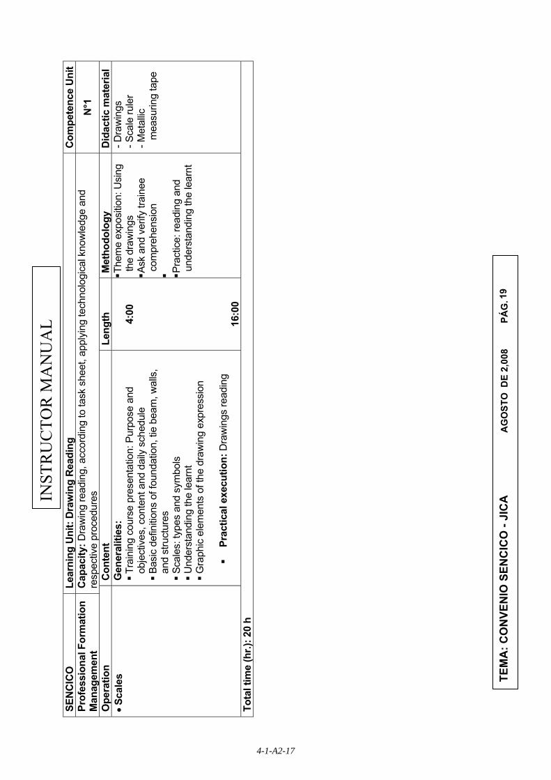
SEN
CIC
O
Lear
ning
Uni
t: D
raw
ing
Rea
ding
C
ompe
tenc
e U
nit
Prof
essi
onal
For
mat
ion
Man
agem
ent
Cap
acity
: Dra
win
g re
adin
g, a
ccor
ding
to ta
sk s
heet
, app
lyin
g te
chno
logi
cal k
now
ledg
e an
d re
spec
tive
proc
edur
es
N°1
Ope
ratio
n C
onte
nt
Leng
th
Met
hodo
logy
D
idac
tic m
ater
ial
• Sca
les
Gen
eral
ities
: T
rain
ing
cour
se p
rese
ntat
ion:
Pur
pose
and
ob
ject
ives
, con
tent
and
dai
ly s
ched
ule
Bas
ic d
efin
ition
s of
foun
datio
n, ti
e be
am, w
alls
, an
d st
ruct
ures
S
cale
s: ty
pes
and
sym
bols
U
nder
stan
ding
the
lear
nt
Gra
phic
ele
men
ts o
f the
dra
win
g ex
pres
sion
Pr
actic
al e
xecu
tion:
Dra
win
gs re
adin
g
4:
00
16
:00
Them
e ex
posi
tion:
Usi
ng
the
draw
ings
A
sk a
nd v
erify
trai
nee
com
preh
ensi
on
Pra
ctic
e: re
adin
g an
d un
ders
tand
ing
the
lear
nt
- Dra
win
gs
- Sca
le ru
ler
- Met
allic
m
easu
ring
tape
Tota
l tim
e (h
r.): 2
0 h
4-1-A2-17
20
INST
RU
CTO
R M
AN
UA
L
TEM
A: C
ON
VEN
IO S
ENC
ICO
- JI
CA
A
GO
STO
DE
2,00
8
P
ÁG
.
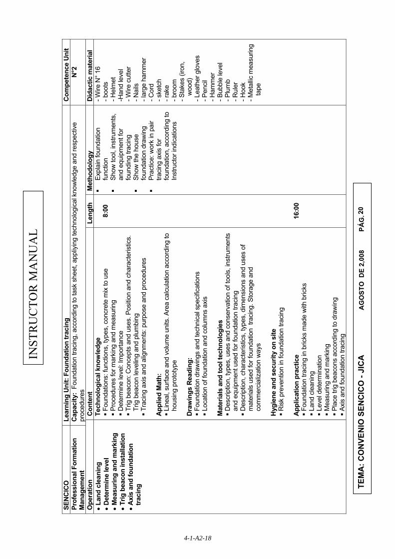
SEN
CIC
O
Lear
ning
Uni
t: Fo
unda
tion
trac
ing
Com
pete
nce
Uni
t Pr
ofes
sion
al F
orm
atio
n M
anag
emen
t C
apac
ity:
Foun
datio
n tra
cing
, acc
ordi
ng to
task
she
et, a
ppliy
ing
tech
nolo
gica
l kno
wle
dge
and
resp
ectiv
e pr
oced
ures
N
°2
Ope
ratio
n C
onte
nt
Leng
th
Met
hodo
logy
D
idac
tic m
ater
ial
• La
nd c
lean
ing
•
Det
erm
ine
leve
l •
Mea
surin
g an
d m
arki
ng
• Tr
ig b
eaco
n in
stal
latio
n •
Axi
s an
d fo
unda
tion
traci
ng
Tech
nolo
gica
l kno
wle
dge
Fou
ndat
ions
: fun
ctio
ns, t
ypes
, con
cret
e m
ix to
use
P
roce
dure
s fo
r mar
king
and
mea
surin
g D
eter
min
e le
vel:
Impo
rtanc
e T
rig b
eaco
n: C
once
pts
and
uses
. Pos
ition
and
cha
ract
eris
tics.
Tr
ig b
eaco
n le
velin
g an
d pl
umbi
ng
Tra
cing
axi
s an
d al
ignm
ents
: pur
pose
and
pro
cedu
res
App
lied
Mat
h:
Lin
eal,
surfa
ce a
nd v
olum
e un
its. A
rea
calc
ulat
ion
acco
rdin
g to
ho
usin
g pr
otot
ype
Dra
win
gs R
eadi
ng:
Fou
ndat
ion
draw
ings
and
tech
nica
l spe
cific
atio
ns
Loc
atio
n of
foun
datio
n an
d co
lum
ns a
xis
Mat
eria
ls a
nd to
ol te
chno
logi
es
Des
crip
tion,
type
s, u
ses
and
cons
erva
tion
of to
ols,
inst
rum
ents
an
d eq
uipm
ent u
sed
for f
ound
atio
n tra
cing
D
escr
iptio
n, c
hara
cter
istic
s, ty
pes,
dim
ensi
ons
and
uses
of
mat
eria
ls u
sed
for f
ound
atio
n tr
acin
g. S
tora
ge a
nd
com
mer
cial
izat
ion
way
s H
ygie
ne a
nd s
ecur
ity o
n si
te
Ris
k pr
even
tion
in fo
unda
tion
traci
ng
App
licat
ion
prac
tice
Fou
ndat
ion
traci
ng in
bric
ks m
ade
with
bric
ks
Lan
d cl
eani
ng
Lev
el d
eter
min
atio
n M
easu
ring
and
mar
king
P
lace
trig
bea
cons
acc
ordi
ng to
dra
win
g A
xis
and
foun
datio
n tra
cing
8:
00
16
:00
Ex
plai
n fo
unda
tion
func
tion
Sh
ow to
ol, i
nstru
men
ts,
and
equi
pmen
t for
fo
undi
ng tr
acin
g
Show
the
hous
e fo
unda
tion
draw
ing
Pr
actic
e: w
ork
in p
air
traci
ng a
xis
for
foun
datio
n, a
ccor
ding
to
Inst
ruct
or in
dica
tions
- Wire
N° 1
6 - b
oots
- H
elm
et
-Han
d le
vel
- Wire
cut
ter
- Nai
ls
- lar
ge h
amm
er
- Cor
d - s
ketc
h - r
ake
- bro
om
- Sta
kes
(iron
, w
ood)
- L
eath
er g
love
s - P
enci
l - H
amm
er
- Bub
ble
leve
l - P
lum
b - R
uler
- H
ook
- Met
allic
mea
surin
g ta
pe
4-1-A2-18

21
INST
RU
CTO
R M
AN
UA
L
TEM
A: C
ON
VEN
IO S
ENC
ICO
- JI
CA
A
GO
STO
DE
2,00
8
P
ÁG
.
Tota
l tim
e (h
r.): 1
8 h
SEN
CIC
O
Lear
ning
Uni
t: D
itch
Exca
vatio
n C
ompe
tenc
e U
nit
Prof
essi
onal
For
mat
ion
Man
agem
ent
Cap
acity
: D
itch
exca
vatio
n, a
ccor
ding
to ta
sk s
heet
, app
lyin
g te
chno
logi
cal k
now
ledg
e an
d re
spec
tive
proc
edur
es
N°3
Ope
ratio
n C
onte
nt
Leng
thM
etho
dolo
gy
Did
actic
mat
eria
l • D
itch
mak
ing
• Ditc
h fin
ishi
ng
Tech
nolo
gica
l kno
wle
dge
Ditc
h: m
inim
um le
ngth
and
wid
th fo
r a s
eism
ic-re
sist
ant
hous
e D
itch
mak
ing
purp
ose
Ditc
h fin
ishi
ng: I
mpo
rtanc
e M
inim
um re
quire
men
ts (2
.0, 2
.1)
Dra
win
gs R
eadi
ng:
Ditc
h de
pth
draw
ings
and
tech
nica
l spe
cific
atio
ns
(Min
imum
requ
irem
ents
) M
ater
ials
and
tool
tech
nolo
gies
D
escr
iptio
n, ty
pes,
use
s an
d co
nser
vatio
n of
tool
s,
inst
rum
ents
and
equ
ipm
ent u
sed
for d
itch
exca
vatio
n D
escr
iptio
n, c
hara
cter
istic
s, ty
pes,
dim
ensi
ons
and
uses
of
mat
eria
ls u
sed
for d
itch
exca
vatio
n. S
tora
ge a
nd
com
mer
cial
izat
ion
way
s H
ygie
ne a
nd s
ecur
ity o
n si
te
Ris
k pr
even
tion
in d
itch
exca
vatio
n an
d fin
ishi
ng
App
licat
ion
prac
tice
Ditc
h m
akin
g
Ditc
h fin
ishi
ng
2:00
8:
00
Exp
lana
tion
and
dem
onst
ratio
n A
pply
writ
ten
test
R
eadi
ng a
nd c
omm
ents
of
SEN
CIC
O a
nd
mak
ers
leaf
let
Pra
ctic
e: w
ork
indi
vidu
ally
. Com
men
t ab
out t
echn
ical
sp
ecifi
catio
ns o
n a
give
n dr
awin
g A
pply
eva
luat
ion
- Sho
vel
- Ste
el b
ar
- boo
ts
- Hel
met
- H
and
leve
l - P
ick
- Cor
d - s
ketc
h - b
uggy
- M
etal
lic
mea
surin
g ta
pe
Tota
l tim
e (h
r.): 1
0 h
4-1-A2-19

22
INST
RU
CTO
R M
AN
UA
L
TEM
A: C
ON
VEN
IO S
ENC
ICO
- JI
CA
A
GO
STO
DE
2,00
8
P
ÁG
.
SEN
CIC
O
Lear
ning
Uni
t: Fr
amew
ork
mak
ing
for c
olum
ns
Com
pete
nce
Uni
t Pr
ofes
sion
al F
orm
atio
n M
anag
emen
t C
apac
ity:
Fram
ewor
k m
akin
g fo
r col
umns
, acc
ordi
ng to
task
she
et, a
pply
ing
tech
nolo
gica
l kno
wle
dge
and
resp
ectiv
e pr
oced
ures
N
°4
Ope
ratio
n C
onte
nt
Leng
thM
etho
dolo
gy
Did
actic
mat
eria
l • M
ark
and
mea
surin
g • W
ire c
uttin
g • S
teel
bar
cut
ting
• Ste
el b
ar b
endi
ng
• Mar
k an
d di
strib
utio
n of
ho
ops
• Plu
mb
linin
g • F
ix fr
amew
ork
Tech
nolo
gica
l kno
wle
dge
Col
umn:
func
tion
Pre
pare
ste
el b
ars:
pur
pose
and
pro
cedu
res.
Ele
men
ts.
Stee
l dis
tribu
tion
in c
onfin
ed m
ason
ry.
Hoo
ps, a
ncho
rs, a
nd s
pace
rs. F
unct
ion
and
dist
ribut
ion
Fra
me
wor
k: d
efin
ition
, cha
ract
eris
tics
and
spec
ifica
tions
M
inim
um re
quire
men
ts (2
.0, 2
.2, 3
.0, 3
.1, 3
.3)
App
lied
Mat
hem
atic
s:
Inte
rnat
iona
l Sys
tem
of U
nits
. Lon
gitu
de u
nits
D
raw
ing
read
ing
Col
umn
draw
ings
and
tech
nica
l spe
cific
atio
ns
Mat
eria
ls a
nd to
ol te
chno
logi
es
Des
crip
tion,
type
s, u
ses
and
cons
erva
tion
of to
ols,
in
stru
men
ts a
nd e
quip
men
t use
d to
mak
e co
lum
n fra
mew
ork
Des
crip
tion,
cha
ract
eris
tics,
type
s, d
imen
sion
s an
d us
es
of m
ater
ials
use
d to
mak
e co
lum
n fra
mew
ork
Hyg
iene
and
sec
urity
on
site
R
isk
prev
entio
n in
col
umn
fram
ewor
k m
akin
g an
d fix
ing
App
licat
ion
prac
tice
Wire
, ste
el c
ut
Ste
el b
endi
ng
Mar
k an
d di
strib
utio
n of
hoo
ps
Plu
mb
linin
g P
repa
re fr
amew
ork
F
ram
ewor
k fix
ing
7:00
15
:00
Col
umn
func
tion
expl
ain
Hoo
ps c
riter
ia a
nd
impo
rtanc
e of
di
strib
utio
n S
how
ske
tch
and
draw
ings
O
rgan
ize
grou
ps to
m
ake
colu
mn
fram
ewor
ks
- wire
n° 1
6 - S
teel
pre
para
tion
tabl
e - c
hise
ls
- saw
for m
etal
s - M
etal
cut
ter
- Sm
all c
oncr
ete
bloc
ks
- Saf
ety
eyeg
lass
- G
love
s - H
amm
er
- Met
allic
m
easu
ring
tape
- H
ook
- Iro
n pi
pe
- Met
allic
m
easu
ring
tape
Tota
l tim
e (h
r.): 2
2 h
4-1-A2-20

23
INST
RU
CTO
R M
AN
UA
L
TEM
A: C
ON
VEN
IO S
ENC
ICO
- JI
CA
A
GO
STO
DE
2,00
8
P
ÁG
.
SEN
CIC
O
Lear
ning
Uni
t: Fo
unda
tion
Bui
ldin
g C
ompe
tenc
e U
nit
Prof
essi
onal
For
mat
ion
Man
agem
ent
Cap
acity
: Fo
unda
tion
Build
ing,
acc
ordi
ng to
task
she
et, a
pply
ing
tech
nolo
gica
l kno
wle
dge
and
resp
ectiv
e pr
oced
ures
N
°5
Ope
ratio
n C
onte
nt
Leng
thM
etho
dolo
gy
Did
actic
mat
eria
l • C
oncr
ete
Prep
arat
ion
• Con
cret
e po
urin
g Te
chno
logi
cal k
now
ledg
e P
urpo
se o
f con
cret
e m
ix p
repa
ratio
n P
urpo
se o
f con
cret
e m
ix p
ourin
g C
oncr
ete:
con
cept
, pro
porti
on a
nd m
ixin
g C
oncr
ete
trans
port
and
pour
ing
in th
e co
nstru
ctio
n si
te
Min
imum
requ
irem
ents
(1.0
, 1.3
(a) 2
.0, 2
.2(a
) A
pplie
d M
athe
mat
ics:
B
asic
ope
ratio
ns w
ith ro
und
num
bers
and
dec
imal
s D
raw
ing
read
ing
Tec
hnic
al s
peci
ficat
ions
inte
rpre
tatio
n To
ols,
Inst
rum
ents
, Equ
ipm
ent a
nd C
onst
ruct
ion
mat
eria
ls (T
IEC
) Tec
hnol
ogy
Com
pone
nts:
cem
ent,
aggr
egat
es, w
ater
D
escr
iptio
n, ty
pes,
use
s an
d ke
epin
g of
Too
ls,
inst
rum
ents
, equ
ipm
ents
and
mat
eria
ls
Hyg
iene
and
sec
urity
on
site
P
reca
utio
ns fo
r con
cret
e pr
epar
atio
n
Des
crip
tion
of th
e op
erat
ion:
o
Prep
are
conc
rete
o
Con
cret
e po
urin
g A
pplic
atio
n pr
actic
e P
repa
re c
oncr
ete
Con
cret
e po
urin
g
2:00
8:
00
Sho
w th
e co
ncre
te
Indi
cate
the
trans
port
form
to th
e co
nstru
ctio
n si
te
Ver
ify th
e se
curit
y ru
les
fulfi
llmen
t in
tran
spor
t an
d in
stal
l of c
oncr
ete
on c
onst
ruct
ion
site
, an
d in
the
use
of
conc
rete
pou
ring
m
achi
nes
Rea
ding
and
com
men
ts
of S
ENC
ICO
and
m
aker
s le
afle
ts
Indi
vidu
al p
ract
ice,
pr
epar
ing
and
mix
ing
the
conc
rete
acc
ordi
ng
to a
n in
dica
ted
pr
opor
tion
App
ly a
writ
ten
test
- Cem
ent
- San
d - W
ater
- C
rush
ed s
tone
- H
orm
igon
- S
hove
l - P
ick
- Bug
gy
- Mix
er
Tota
l tim
e (h
r.): 1
0 h
4-1-A2-21

24
INST
RU
CTO
R M
AN
UA
L
TEM
A: C
ON
VEN
IO S
ENC
ICO
- JI
CA
A
GO
STO
DE
2,00
8
P
ÁG
.
SEN
CIC
O
Lear
ning
Uni
t: Fr
amew
ork
mak
ing
for R
C ti
e be
am
Com
pete
nce
Uni
t Pr
ofes
sion
al F
orm
atio
n M
anag
emen
t C
apac
ity:
Fram
ewor
k m
akin
g fo
r RC
tie
beam
s, a
ccor
ding
to ta
sk s
heet
, app
lyin
g te
chno
logi
cal k
now
ledg
e an
d re
spec
tive
proc
edur
es
N°6
Ope
ratio
n C
onte
nt
Leng
thM
etho
dolo
gy
Did
actic
mat
eria
l • M
easu
re a
nd m
ark
• Wire
cut
ting
• Ste
el c
uttin
g • S
teel
ben
ding
• M
ark
and
dist
ribut
ion
of
Stirr
ups
• Plu
mb
linin
g • F
ram
ewor
k fix
ing
Tech
nolo
gica
l kno
wle
dge
Pur
pose
of s
teel
alig
nmen
t P
urpo
se o
f ste
el ty
ing
C
over
F
unct
ion
of th
e an
chor
s M
inim
um re
quire
men
ts (2
.0, 2
.2(b
) TI
EC T
echn
olog
y
Des
crip
tion,
type
s, u
ses
and
cons
erva
tion
of h
ook,
leat
her
glov
es, s
afet
y ey
egla
ss
Dra
win
g re
adin
g C
olum
n dr
awin
gs a
nd te
chni
cal s
peci
ficat
ions
H
ygie
ne a
nd s
ecur
ity o
n co
nstru
ctio
n si
te
Sec
urity
rule
s in
the
wor
k w
ith s
teel
P
reca
utio
ns w
hen
stee
l is
bein
g tie
A
pplic
atio
n pr
actic
e S
teel
alig
nmen
t S
teel
tyin
g
6:00
14
:00
Col
umn
func
tion
expl
anat
ion
Stir
rups
dis
tribu
tion
crite
ria a
nd im
porta
nce
Org
aniz
e gr
oups
for
stee
l alig
nmen
t and
ty
ing
- wire
n° 1
6 - S
teel
pre
para
tion
tabl
e - c
hise
ls
- Tre
stle
s - M
etal
cut
ter
- Sm
all c
oncr
ete
bloc
ks
- Saf
ety
eyeg
lass
- G
love
s - H
amm
er
- Met
allic
m
easu
ring
tape
- T
orto
l -
Iron
Pipe
Tota
l tim
e (h
r.): 2
0 h
4-1-A2-22

25
INST
RU
CTO
R M
AN
UA
L
TEM
A: C
ON
VEN
IO S
ENC
ICO
- JI
CA
A
GO
STO
DE
2,00
8
P
ÁG
.
SEN
CIC
O
Lear
ning
Uni
t: Pr
epar
e bo
ard
and
tie b
eam
form
wor
k C
ompe
tenc
e U
nit
Prof
essi
onal
For
mat
ion
Man
agem
ent
Cap
acity
: Pr
epar
e bo
ard
and
tie b
eam
form
wor
k, a
ccor
ding
to ta
sk s
heet
, app
lyin
g te
chno
logi
cal k
now
ledg
e an
d re
spec
tive
proc
edur
es
N°7
Ope
ratio
n C
onte
nt
Leng
thM
etho
dolo
gy
Did
actic
mat
eria
l • S
aw b
y ha
nd
• Nai
ling
and
perfo
ratin
g • D
orm
ant f
ixin
g • F
ixin
g po
intd
rill
• Ins
tall
boar
d • P
lum
b lin
ing
Tech
nolo
gica
l kno
wle
dge
Pur
pose
of s
aw b
y ha
nd
Pur
pose
of n
ailin
g an
d pe
rfora
ting
Pur
pose
of f
ixin
g a
dorm
ant
Pur
pose
of f
ixin
g po
intd
rill
Pur
pose
of i
nsta
lling
boar
d D
efin
ition
and
type
s of
tie
beam
s F
orm
wor
ks, d
efin
ition
, typ
es, u
ses
Woo
d, w
ood
to u
se
Min
imum
requ
irem
ents
(2.0
, 2.2
(b)
App
lied
mat
hem
atic
s M
etho
d fo
r woo
d cu
bica
tion
TIEC
Tec
hnol
ogy
D
escr
iptio
n, ty
pes,
use
s an
d co
nser
vatio
n of
ham
mer
, pr
ess,
woo
d sa
w, c
arpe
nter
hoo
k, s
take
s H
ygie
ne a
nd s
ecur
ity o
n co
nstru
ctio
n si
te
Sec
urity
rule
s in
the
wor
k w
ith s
teel
P
reca
utio
ns w
hen
stee
l is
bein
g tie
A
pplic
atio
n pr
actic
e S
teel
alig
nmen
t S
teel
tyin
g
6:00
14
:00
Col
umn
func
tion
expl
anat
ion
Stir
rups
dis
tribu
tion
crite
ria a
nd im
porta
nce
Org
aniz
e gr
oups
for
stee
l alig
nmen
t and
ty
ing
- Ham
mer
- M
etal
lic
mea
surin
g ta
pe
- car
pent
er p
enci
l - N
ails
- P
lum
b lin
ing
- Cor
d - W
ire n
°16
- Set
squ
are
- woo
d - w
ood
drille
r - H
ook
- Sta
kes
- Hel
met
s - B
oots
- S
afet
y ey
egla
ss
- Glo
ves
Tota
l tim
e (h
r.): 2
0 h
4-1-A2-23

26
INST
RU
CTO
R M
AN
UA
L
TEM
A: C
ON
VEN
IO S
ENC
ICO
- JI
CA
A
GO
STO
DE
2,00
8
P
ÁG
.
SEN
CIC
O
Lear
ning
Uni
t: Ti
e be
am b
uild
ing
Com
pete
nce
Uni
t Pr
ofes
sion
al F
orm
atio
n M
anag
emen
t C
apac
ity:
Bui
ldin
g of
tie
beam
, acc
ordi
ng to
task
she
et, a
pply
ing
tech
nolo
gica
l kno
wle
dge
and
resp
ectiv
e pr
oced
ures
N
°8
Ope
ratio
n C
onte
nt
Leng
thM
etho
dolo
gy
Did
actic
mat
eria
l • M
easu
ring
and
mar
k • T
ie b
eam
trac
ing
• Pre
pare
form
wor
k el
emen
ts
• For
mw
ork
asse
mbl
ing
and
fixin
g • C
oncr
ete
prep
arat
ion
• Con
cret
e po
urin
g an
d ho
mog
enat
ing
• Tak
en o
ut th
e Fo
rmw
ork
and
curin
g
Tech
nolo
gica
l kno
wle
dge
Tie
bea
m: C
once
pt, f
unct
ion
and
type
s. T
raci
ng te
chni
ques
F
orm
wor
ks: C
once
pt fu
nctio
ns a
nd ty
pes.
Ele
men
ts
Cut
, pla
ne te
chni
ques
for w
ood
Nai
ling,
hoo
king
, lev
elin
g, p
lum
b lin
ing
and
secu
ring
of w
ood
form
wro
ks
Con
cret
e pr
opor
tions
for t
ie b
eam
s C
oncr
ete
pour
ing
and
hom
ogen
izin
g in
tie
beam
s. P
roce
dure
T
akin
g th
e fo
rmw
ork
out a
nd ti
e be
am c
urin
g: p
roce
dure
and
tim
es
For
mw
orks
ele
men
ts s
tora
ge
Min
imum
requ
irem
ents
(1.0
, 1.2
(a,b
,c,d
)) A
pplie
d m
athe
mat
ics
Lon
gitu
de, a
rea
and
volu
me
units
D
raw
ing
read
ing
For
mw
orks
dra
win
gs ,
stru
ctur
es d
etai
ls a
nd te
chni
cal
spec
ifica
tions
TI
EC T
echn
olog
y W
ood
for f
orm
wor
k: d
escr
iptio
n, ty
pes,
sel
ectio
ns a
nd u
ses.
U
sual
uni
ts a
nd c
omm
erci
aliz
atio
n m
ode.
Sto
rage
. Woo
d dr
ying
D
escr
iptio
n, ty
pes,
use
s. a
nd c
onse
rvat
ion
of to
ols,
in
stru
men
ts a
nd e
quip
men
t for
tie
beam
. H
ygie
ne a
nd s
ecur
ity o
n co
nstru
ctio
n si
te
Ris
k pr
even
tion
in p
repa
ratio
n, p
ourin
g an
d ho
mog
eniz
ing
of
tie b
eam
s A
pplic
atio
n pr
actic
e T
ie b
eam
bui
ldin
g:
o Ti
e be
am tr
acin
g ac
cord
ing
to te
chni
cal s
peci
ficat
ions
o
Prep
are
elem
ents
for f
orm
wor
ks
o As
sem
ble
and
fix ti
e be
am fo
rmw
ork
o C
oncr
ete
prep
arat
ion
and
pour
ing
in ti
e be
am
o Ta
king
out
the
form
wor
k an
d tie
bea
m c
urin
g
2:00
8:
00
Tie
bea
mfu
nctio
n ex
plan
atio
n F
orm
wor
ks a
nd it
s el
emen
ts fu
nctio
n ex
plan
atio
n S
how
woo
ds fo
r fo
rmw
orks
- wire
n° 1
6 - W
ater
- A
ggre
gate
s - C
emen
t - P
lane
- N
ails
- C
oncr
ete
can
- Woo
d fo
r fo
rmw
ork
- ham
mer
- O
chre
- S
aw
- Hoo
k - M
etal
lic m
easu
re
tape
4-1-A2-24

27
INST
RU
CTO
R M
AN
UA
L
TEM
A: C
ON
VEN
IO S
ENC
ICO
- JI
CA
A
GO
STO
DE
2,00
8
P
ÁG
.
Tota
l tim
e (h
r.): 1
0 h
SEN
CIC
O
Lear
ning
Uni
t: Ti
e be
am b
uild
ing
Com
pete
nce
Uni
t Pr
ofes
sion
al F
orm
atio
n M
anag
emen
t C
apac
ity:
Bui
ldin
g of
tie
beam
, acc
ordi
ng to
task
she
et, a
pply
ing
tech
nolo
gica
l kno
wle
dge
and
resp
ectiv
e pr
oced
ures
N
°8
Ope
ratio
n C
onte
nt
Leng
thM
etho
dolo
gy
Did
actic
mat
eria
l • M
easu
ring
and
mar
k • T
ie b
eam
trac
ing
• Pre
pare
form
wor
k el
emen
ts
• For
mw
ork
asse
mbl
ing
and
fixin
g • C
oncr
ete
prep
arat
ion
• Con
cret
e po
urin
g an
d ho
mog
enat
ing
• Tak
en o
ut th
e Fo
rmw
ork
and
curin
g
Tech
nolo
gica
l kno
wle
dge
Tie
bea
m: C
once
pt, f
unct
ion
and
type
s. T
raci
ng te
chni
ques
F
orm
wor
ks: C
once
pt fu
nctio
ns a
nd ty
pes.
Ele
men
ts
Cut
, pla
ne te
chni
ques
for w
ood
Nai
ling,
hoo
king
, lev
elin
g, p
lum
b lin
ing
and
secu
ring
of w
ood
form
wro
ks
Con
cret
e pr
opor
tions
for t
ie b
eam
s C
oncr
ete
pour
ing
and
hom
ogen
izin
g in
tie
beam
s. P
roce
dure
T
akin
g th
e fo
rmw
ork
out a
nd ti
e be
am c
urin
g: p
roce
dure
and
tim
es
For
mw
orks
ele
men
ts s
tora
ge
Min
imum
requ
irem
ents
(1.0
, 1.2
(a,b
,c,d
)) A
pplie
d m
athe
mat
ics
Lon
gitu
de, a
rea
and
volu
me
units
D
raw
ing
read
ing
For
mw
orks
dra
win
gs ,
stru
ctur
es d
etai
ls a
nd te
chni
cal
spec
ifica
tions
TI
EC T
echn
olog
y W
ood
for f
orm
wor
k: d
escr
iptio
n, ty
pes,
sel
ectio
ns a
nd u
ses.
U
sual
uni
ts a
nd c
omm
erci
aliz
atio
n m
ode.
Sto
rage
. Woo
d dr
ying
D
escr
iptio
n, ty
pes,
use
s. a
nd c
onse
rvat
ion
of to
ols,
in
stru
men
ts a
nd e
quip
men
t for
tie
beam
. H
ygie
ne a
nd s
ecur
ity o
n co
nstru
ctio
n si
te
Ris
k pr
even
tion
in p
repa
ratio
n, p
ourin
g an
d ho
mog
eniz
ing
of
tie b
eam
s A
pplic
atio
n pr
actic
e T
ie b
eam
bui
ldin
g:
o Ti
e be
am tr
acin
g ac
cord
ing
to te
chni
cal s
peci
ficat
ions
o
Prep
are
elem
ents
for f
orm
wor
ks
o As
sem
ble
and
fix ti
e be
am fo
rmw
ork
o C
oncr
ete
prep
arat
ion
and
pour
ing
in ti
e be
am
o Ta
king
out
the
form
wor
k an
d tie
bea
m c
urin
g
2:00
8:
00
Tie
bea
mfu
nctio
n ex
plan
atio
n F
orm
wor
ks a
nd it
s el
emen
ts fu
nctio
n ex
plan
atio
n S
how
woo
ds fo
r fo
rmw
orks
- wire
n° 1
6 - W
ater
- A
ggre
gate
s - C
emen
t - P
lane
- N
ails
- C
oncr
ete
can
- Woo
d fo
r fo
rmw
ork
- ham
mer
- O
chre
- S
aw
- Hoo
k - M
etal
lic m
easu
re
tape
4-1-A2-25

28
INST
RU
CTO
R M
AN
UA
L
TEM
A: C
ON
VEN
IO S
ENC
ICO
- JI
CA
A
GO
STO
DE
2,00
8
P
ÁG
.
Tota
l tim
e (h
r.): 1
0 h
SEN
CIC
O
Lear
ning
Uni
t: M
akin
g w
all t
empl
ate
Com
pete
nce
Uni
t Pr
ofes
sion
al F
orm
atio
n M
anag
emen
t C
apac
ity:
Mak
ing
wal
l tem
plat
e, a
ccor
ding
to ta
sk s
heet
, app
lyin
g te
chno
logi
cal
know
ledg
e an
d re
spec
tive
proc
edur
es
N°9
Ope
ratio
n C
onte
nt
Leng
thM
etho
dolo
gy
Did
actic
mat
eria
l • M
easu
ring
and
mar
k • B
rick
dist
ribut
ion
• Bric
k cu
tting
• A
lignm
ent
• Pre
pare
ver
tical
bric
k la
yer d
istr
ibut
ion
rule
r
Tech
nolo
gica
l kno
wle
dge
Wal
ls: C
once
pt
Tem
plat
e te
chni
que:
Con
cept
and
pur
pose
B
rick
cutti
ng: p
urpo
se, p
roce
dure
s D
istri
butio
n: b
rick
tie, b
rick
unio
n L
ayer
s Es
cant
illon:
des
crip
tion,
type
s an
d us
es
Min
imum
requ
irem
ents
(1.0
, 1.5
(a) –
3.0
, 3.4
) A
pplie
d m
athe
mat
ics
Mat
eria
ls C
alcu
latio
n D
raw
ing
read
ing
Hou
sing
arc
hite
ctur
al d
raw
ings
, det
ails
TI
EC T
echn
olog
y B
rick:
Des
crip
tion,
type
s an
d us
es. M
ore
frequ
ent d
imen
sion
s D
escr
iptio
n, ty
pes,
use
s. a
nd c
onse
rvat
ion
of to
ols,
in
stru
men
ts a
nd e
quip
men
t for
mak
ing
wal
l tem
plat
e.
Hyg
iene
and
sec
urity
on
cons
truct
ion
site
P
reca
utio
ns in
use
of t
ools
and
inst
rum
ents
for m
akin
g w
all
tem
plat
e A
pplic
atio
n pr
actic
e D
istri
butin
g an
d al
ignm
ent o
f bric
ks
Bric
k cu
tting
acc
ordi
ng re
quire
men
t P
repa
re v
ertic
al b
rick
laye
r dis
tribu
tion
rule
r
7:00
20
:00
Exp
lain
ing
wal
l tem
plat
e te
chni
ques
and
bric
k tie
E
xpla
inin
g br
ick
cutti
ng
tech
niqu
es
Exp
lain
ing
verti
cal b
rick
laye
r dis
tribu
tion
rule
r pr
epar
atio
n pr
oced
ure
Sho
w to
ols,
inst
rum
ents
an
d eq
uipm
ents
for
mak
ing
wal
l tem
plat
e D
escr
ibe
crite
ria fo
r pip
es
inst
alla
tion
- Bric
k - H
elm
et
- Chi
sels
- C
ord
- Squ
are
set
- saf
ety
eyeg
lass
- C
arpe
nter
pen
- L
umbe
r - P
lum
b lin
ing
- Woo
d sp
acer
- M
etal
lic m
easu
re
tape
Tota
l tim
e (h
r.): 2
7:00
h
4-1-A2-26

29
INST
RU
CTO
R M
AN
UA
L
TEM
A: C
ON
VEN
IO S
ENC
ICO
- JI
CA
A
GO
STO
DE
2,00
8
P
ÁG
.
SEN
CIC
O
Lear
ning
Uni
t: W
all b
uild
ing
Com
pete
nce
Uni
t Pr
ofes
sion
al F
orm
atio
n M
anag
emen
t C
apac
ity:
Wal
l bui
ldin
g, a
ccor
ding
to ta
sk s
heet
, app
lyin
g te
chno
logi
cal k
now
ledg
e an
d re
spec
tive
proc
edur
es
N°1
0
Ope
ratio
n C
onte
nt
Leng
thM
etho
dolo
gy
Did
actic
mat
eria
l • L
evel
det
erm
inat
ion
• Mea
surin
g an
d m
ark
• Bric
k di
strib
utio
n • B
rick
cutti
ng
• Ins
tall
elec
tric
in
stal
latio
ns p
ipes
• B
rick
alig
nmen
t • M
orta
r pre
para
tion
• Bric
k in
stal
latio
n
Tech
nolo
gica
l kno
wle
dge
Cle
anin
g re
gist
er: P
urpo
se a
nd p
repa
ratio
n w
ays
Mor
tar:
Def
initi
on, c
hara
cter
istic
s, m
orta
r pre
para
tion
proc
edur
e B
rick
inst
alla
tion
proc
edur
e P
ipes
and
ele
ctric
box
inst
alla
tion
Min
imum
requ
irem
ents
(1.0
, 1.2
(a),
1.5(
b), 1
.3(a
) – 2
.0, 2
.2(b
)) A
pplie
d m
athe
mat
ics
Are
a an
d vo
lum
e C
alcu
latio
n P
ropo
rtion
s fo
r mor
tar p
repa
ratio
n D
raw
ing
read
ing
Hou
sing
arc
hite
ct a
nd s
truct
ure
draw
ings
W
all s
ymbo
lizat
ion
TIEC
Tec
hnol
ogy
Mor
tar c
ompo
nent
s: c
once
pts,
type
s an
d ap
plic
atio
ns o
f ce
men
t, ag
greg
ates
and
wat
er
Des
crip
tion,
type
s, u
ses.
and
con
serv
atio
n of
tool
s,
inst
rum
ents
and
equ
ipm
ent f
or w
all b
uild
ing.
H
ygie
ne a
nd s
ecur
ity o
n co
nstru
ctio
n si
te
Pre
caut
ions
in u
se o
f too
ls a
nd in
stru
men
ts fo
r wal
l bui
ldin
g A
pplic
atio
n pr
actic
e W
all b
uild
ing
o Pr
epar
e cl
eani
ng re
gist
er, a
ccor
ding
to in
dica
tions
o
Prep
are
mor
tar
o In
stal
l bric
ks
o In
stal
l rei
nfor
cem
ent s
teel
in v
anes
o
Inst
all p
ipes
in b
rick
perfo
ratio
n o
Inst
all e
lect
ric in
stal
latio
n bo
xes
7:00
20
:00
Exp
lain
the
purp
ose
of
clea
ning
regi
ster
pr
epar
atio
n E
xpla
in re
info
rcem
ent
func
tions
and
loca
tion
crite
ria
Exp
lain
impo
rtanc
e of
wal
l re
info
rcem
ent
Sho
w d
raw
ings
that
in
dica
te lo
catio
n of
re
info
rcem
ent a
nd
inst
alla
tions
- Wat
er
- Bric
k - S
and
- Hel
met
- B
uggy
- C
hise
ls
- Cor
d - S
quar
e se
t - s
afet
y ey
egla
ss
- Car
pent
er p
en
- cem
ent
- Plu
mb
linin
g - W
ood
spac
er
- Met
allic
mea
sure
ta
pe
- Bric
k la
yer
verti
cal r
uler
- S
hove
l
Tota
l tim
e (h
r.): 2
7:00
h
4-1-A2-27

30
INST
RU
CTO
R M
AN
UA
L
TEM
A: C
ON
VEN
IO S
ENC
ICO
- JI
CA
A
GO
STO
DE
2,00
8
P
ÁG
.
SEN
CIC
O
Lear
ning
Uni
t: M
akin
g fo
rmw
ork
and
pour
ing
conc
rete
in c
olum
ns
Com
pete
nce
Uni
t Pr
ofes
sion
al F
orm
atio
n M
anag
emen
t C
apac
ity:
Mak
ing
form
wor
k an
d po
urin
g co
ncre
te in
col
umns
, acc
ordi
ng to
task
she
et,
appl
ying
tech
nolo
gica
l kno
wle
dge
and
resp
ectiv
e pr
oced
ures
N
°11
Ope
ratio
n C
onte
nt
Leng
thM
etho
dolo
gy
Did
actic
mat
eria
l • L
evel
det
erm
inat
ion
• Mea
surin
g an
d m
ark
• Saw
by
hand
• N
ailin
g an
d pe
rfora
ting
• Dor
man
t fix
ing
• Fix
ing
poin
tdril
l • I
nsta
ll bo
ard
• Plu
mb
linin
g • C
oncr
ete
prep
arat
ion
• Con
cret
e po
urin
g an
d ho
mog
eniz
ing
• Tak
ing
out t
he
Form
wor
k an
d cu
ring
Tech
nolo
gica
l kno
wle
dge
Col
umn:
Con
cept
F
orm
wor
ks: C
once
pt fu
nctio
ns a
nd ty
pes.
Ele
men
ts
Min
imum
requ
irem
ents
(1.0
, 1.1
(a,b
,c,d
)) -
2.0,
2.3
) D
raw
ing
read
ing
Hou
sing
arc
hite
ct a
nd s
truct
ure
draw
ings
C
olum
n sy
mbo
lizat
ion
TIEC
Tec
hnol
ogy
Con
cret
e co
mpo
nent
s: c
once
pts,
type
s an
d ap
plic
atio
ns o
f ce
men
t, ag
greg
ates
and
wat
er
Des
crip
tion,
type
s, u
ses.
and
con
serv
atio
n of
tool
s,
inst
rum
ents
and
equ
ipm
ent f
or c
olum
n fo
rmw
ork
and
conc
rete
po
urin
g H
ygie
ne a
nd s
ecur
ity o
n co
nstru
ctio
n si
te
Pre
caut
ions
in u
se o
f too
ls a
nd in
stru
men
ts fo
r col
umn
form
wor
k an
d co
ncre
te p
ourin
g A
pplic
atio
n pr
actic
e C
olum
n fo
rmw
ork
and
conc
rete
pou
ring
o
Prep
are
and
asse
mbl
e el
emen
ts fo
r col
umn
form
wor
ks
o C
oncr
ete
prep
arat
ion
and
pour
ing
in c
olum
ns
o Ta
king
out
the
form
wor
k an
d co
lum
n cu
ring
4:00
16
:00
Sho
w c
olum
n fo
rmw
ork
grap
hs
Indi
cate
the
colu
mn
form
wor
k el
emen
ts
Poi
nt o
ut th
e im
porta
nce
of p
lum
b lin
ing
and
tole
ranc
es
Exp
lain
the
colu
mn
pour
ing
proc
edur
e
- Wat
er
- San
d - H
elm
et
- Bug
gy
- Nai
ls
- Cor
d - S
quar
e se
t - s
afet
y ey
egla
ss
- Car
pent
er p
en
- Cem
ent
- Cru
shed
sto
ne
- Plu
mb
linin
g - M
etal
lic m
easu
re
tape
- S
hove
l - h
amm
er
- Han
d le
vel
Tota
l tim
e (h
r.): 2
0:00
h
4-1-A2-28

31
INST
RU
CTO
R M
AN
UA
L
TEM
A: C
ON
VEN
IO S
ENC
ICO
- JI
CA
A
GO
STO
DE
2,00
8
P
ÁG
.
SEN
CIC
O
Lear
ning
Uni
t: M
akin
g Fr
amew
ork
and
pour
ing
ring
beam
C
ompe
tenc
e U
nit
Prof
essi
onal
For
mat
ion
Man
agem
ent
Cap
acity
: M
akin
g Fr
amew
ork
and
pour
ing
ring
beam
, acc
ordi
ng to
task
she
et, a
pply
ing
tech
nolo
gica
l kno
wle
dge
and
resp
ectiv
e pr
oced
ures
N
°13
Ope
ratio
n C
onte
nt
Leng
thM
etho
dolo
gy
Did
actic
mat
eria
l • D
eter
min
e le
vel
• Mea
sure
and
mar
k • W
ire c
uttin
g • S
teel
cut
ting
• Ste
el b
endi
ng
• Pre
pare
fram
ewor
k • P
repa
re c
oncr
ete
• Pou
r and
hom
ogen
ize
the
conc
rete
• O
verla
p st
eel b
ars
• Tak
e ou
t the
form
wor
k an
d cu
ring
Tech
nolo
gica
l kno
wle
dge
Rin
g be
am: F
unct
ion,
spe
cific
atio
n an
d lo
catio
n C
onst
ruct
ion
proc
ess:
ste
el a
nd fo
rmw
ork
for r
ing
beam
M
inim
um re
quire
men
ts (2
.0, 2
.2(d
) – 3
.0)
App
lied
mat
hem
atic
s
Bas
ic o
pera
tions
with
roun
d an
d de
cim
al n
umbe
rs. A
rea
and
volu
me
calc
ulat
ion.
P
ropo
rtion
s G
eom
etric
figu
res.
Par
alle
l and
per
pend
icul
ar li
nes
Dra
win
g re
adin
g S
truct
ure
draw
ings
, rin
g be
am id
entif
icat
ion
TIEC
Tec
hnol
ogy
Des
crip
tion,
type
s, u
ses.
and
con
serv
atio
n of
tool
s,
inst
rum
ents
and
equ
ipm
ent f
or ri
ng b
eam
bui
ldin
g H
ygie
ne a
nd s
ecur
ity o
n co
nstru
ctio
n si
te
Sec
urity
rule
s in
the
ring
beam
fram
ewok
and
pou
ring
App
licat
ion
prac
tice
Pre
pare
fram
ewor
k, fo
rmw
ork
and
pour
con
cret
e in
a ri
ng
beam
o
Prep
are
ring
beam
fram
ewor
k o
Prep
are
and
pour
con
cret
e o
Take
out
the
form
wor
k an
d rin
g be
am c
urin
g
6:00
12
:00
Exp
lain
ring
bea
m
func
tion
and
loca
tion
crite
ria
Exp
lain
and
de
mon
stra
te p
roce
dure
to
pre
pare
ste
el a
nd to
m
ake
the
fram
ewor
k E
xpla
in c
oncr
ete
pour
ing
proc
edur
e in
rin
g be
am
- hel
met
- N
ails
- S
afet
y ey
egla
ss
- Sho
vel
- Car
pent
er p
en
- Plu
mb
linin
g - L
umbe
r - w
ood
spac
er
Tota
l tim
e (h
r.): 1
8 h
4-1-A2-29

32
INST
RU
CTO
R M
AN
UA
L
TEM
A: C
ON
VEN
IO S
ENC
ICO
- JI
CA
A
GO
STO
DE
2,00
8
P
ÁG
.
SEN
CIC
O
Lear
ning
Uni
t: Li
ght c
oncr
ete
slab
form
wor
k m
akin
g C
ompe
tenc
e U
nit
Prof
essi
onal
For
mat
ion
Man
agem
ent
Cap
acity
: Li
ght c
oncr
ete
slab
form
wor
k m
akin
g, a
ccor
ding
to ta
sk s
heet
, app
lyin
g te
chno
logi
cal k
now
ledg
e an
d re
spec
tive
proc
edur
es
N°1
4
Ope
ratio
n C
onte
nt
Leng
thM
etho
dolo
gy
Did
actic
mat
eria
l • D
eter
min
e le
vel
• Mea
sure
and
mar
k • H
and
saw
ing
• Nai
ling
• Lum
ber o
verla
ppin
g • P
lum
b lin
ing
• Tak
e ou
t the
form
wor
k
Rin
g be
am fi
F
ix s
mal
l bea
m b
otto
m
Fix
ligh
t con
cret
e sl
ab
form
wor
k ve
rtic
al
supp
ort
Fix
Rin
g be
am e
xter
nal
late
ral b
orde
r
Tech
nolo
gica
l kno
wle
dge
Pur
pose
of r
ing
beam
P
urpo
se o
f sm
all b
eam
bot
tom
fixi
ng
Pur
pose
of l
ight
con
cret
e sl
ab v
ertic
al s
uppo
rt fix
ing
Fix
ring
bea
m e
xter
nal l
ater
al b
orde
r C
onsi
dera
tions
to d
eter
min
e el
emen
t dim
ensi
ons
and
dist
ribut
ion
of th
e lig
ht c
oncr
ete
slab
form
wor
k L
ight
con
cret
e sl
ab fo
rmw
ork:
Def
initi
on, t
ypes
, and
el
emen
ts th
at fo
rm it
M
inim
um re
quire
men
ts (1
.0(c
), 1.
4(a)
) D
raw
ing
read
ing
Stru
ctur
e dr
awin
gs, l
ight
con
cret
e sl
ab id
entif
icat
ion
TIEC
Tec
hnol
ogy
Des
crip
tion,
type
s, u
ses.
and
con
serv
atio
n of
chi
sel
Hyg
iene
and
sec
urity
on
cons
truct
ion
site
S
ecur
ity ru
les
in th
e lig
ht c
oncr
ete
slab
form
wor
k an
d ta
keou
t of f
ram
ewor
k App
licat
ion
prac
tice
Fix
ring
bea
ms
Fix
sm
all b
eam
bot
tom
F
ix c
oncr
ete
slab
ver
tical
sup
port
Fix
sla
b ex
tern
al la
tera
l bor
der
Pre
pare
fram
ewor
k, fo
rmw
ork
and
pour
con
cret
e in
a ri
ng
beam
o
Prep
are
ring
beam
fram
ewor
k o
Prep
are
and
pour
con
cret
e o
Take
out
the
form
wor
k an
d rin
g be
am c
urin
g
4:00
18
:00
Exp
lain
the
elem
ents
th
at fo
rm th
e lig
ht
conc
rete
sla
b fo
rmw
ork
Org
aniz
e gr
oups
for
light
con
cret
e sl
ab
form
wor
k m
akin
g
- Mea
surin
g ta
pe
- plu
mb
linin
g - c
arpe
nter
pen
- s
aw
- ham
mer
- h
and
leve
l - C
arpe
nter
hoo
k - S
quar
e se
t - h
elm
et
- Tab
le fo
r ste
el
wor
k - L
umbe
r - N
ails
- S
afet
y ey
egla
ss
- Car
pent
er p
en
- Boo
ts
- Lea
ther
glo
ves
4-1-A2-30

33
INST
RU
CTO
R M
AN
UA
L
TEM
A: C
ON
VEN
IO S
ENC
ICO
- JI
CA
A
GO
STO
DE
2,00
8
P
ÁG
.
Tota
l tim
e (h
r.): 2
2 h
SEN
CIC
O
Lear
ning
Uni
t:Lig
ht c
oncr
ete
slab
fram
ewor
k m
akin
g C
ompe
tenc
e U
nit
Prof
essi
onal
For
mat
ion
Man
agem
ent
Cap
acity
: Li
ght c
oncr
ete
slab
fram
ewor
k m
akin
g, a
ccor
ding
to ta
sk s
heet
, app
lyin
g te
chno
logi
cal k
now
ledg
e an
d re
spec
tive
proc
edur
es
N°1
5
Ope
ratio
n C
onte
nt
Leng
thM
etho
dolo
gy
Did
actic
mat
eria
l • M
easu
re a
nd m
arki
ng
• Wire
cut
ting
• Ste
el c
uttin
g • S
teel
ben
ding
• S
teel
ove
rlap
• Mar
k st
eel d
istr
ibut
ion
• Ste
el ty
ing
I
nsta
lling
ste
el in
sm
all b
eam
s B
rick
alig
nmen
t I
nsta
lling
iron
ste
el
Tech
nolo
gica
l kno
wle
dge
Pur
pose
of i
nsta
lling
stee
l on
smal
l bea
ms
Lig
ht c
oncr
ete
slab
: def
initi
on, t
ypes
and
ele
men
ts.
Pur
pose
of b
rick
alig
men
t P
urpo
se o
f ins
tallin
g st
eel t
empe
ratu
re
Ste
el te
mpe
ratu
re: D
efin
ition
and
pur
pose
S
mal
l bea
ms:
def
initi
on a
nd p
urpo
se
Pos
itive
and
neg
ativ
e st
eel
Min
imum
requ
irem
ents
(2.0
, 2.1
(d))
Dra
win
g re
adin
g In
terp
reta
tion
of ro
of s
truct
ure
draw
ings
TI
EC T
echn
olog
y D
escr
iptio
n, ty
pes,
use
s a
nd c
onse
rvat
ion
of ro
of b
ricks
H
ygie
ne a
nd s
ecur
ity o
n co
nstru
ctio
n si
te
Sec
urity
rule
s in
the
light
con
cret
e sl
ab b
uild
ing
App
licat
ion
prac
tice
Inst
all i
ron
in s
mal
l bea
ms
Bric
k al
ignm
ent
Inst
al te
mpe
ratu
re s
teel
4:00
14
:00
Exp
lain
the
elem
ents
th
at fo
rm a
ligh
t co
ncre
te s
lab
Org
aniz
e gr
oups
for
light
con
cret
e sl
ab
build
ing
- Mea
surin
g ta
pe
- Hac
k sa
w
- Ste
el
- Cha
lk o
r cra
yon
- Tin
sni
p - T
rap
- Wire
16
- Ste
el p
ipe
- Tab
le fo
r ste
el
wor
k - D
raw
ings
- h
amm
er
- hel
met
- S
afet
y ey
egla
ss
- Car
pent
er p
en
- Boo
ts, h
elm
ets
- Lea
ther
glo
ves
- Roo
f bric
ks
Tota
l tim
e (h
r.): 1
8 h
4-1-A2-31

34
INST
RU
CTO
R M
AN
UA
L
TEM
A: C
ON
VEN
IO S
ENC
ICO
- JI
CA
A
GO
STO
DE
2,00
8
P
ÁG
.
SEN
CIC
O
Lear
ning
Uni
t: Li
ght c
oncr
ete
slab
bui
ldin
g C
ompe
tenc
e U
nit
Prof
essi
onal
For
mat
ion
Man
agem
ent
Cap
acity
: Li
ght c
oncr
ete
slab
bui
ldin
g, a
ccor
ding
to ta
sk s
heet
, app
lyin
g te
chno
logi
cal
know
ledg
e an
d re
spec
tive
proc
edur
es
N°1
6
Ope
ratio
n C
onte
nt
Leng
thM
etho
dolo
gy
Did
actic
mat
eria
l • P
repa
re c
oncr
ete
• Pou
r con
cret
e • T
ake
out t
he fo
rmw
ork
and
cure
• H
omog
eniz
e co
ncre
te
Tech
nolo
gica
l kno
wle
dge
Lig
ht c
oncr
ete
slab
: def
initi
on, e
lem
ents
R
oof s
truct
ure
Pur
pose
of c
oncr
ete
hom
ogen
izat
ion
Min
imum
requ
irem
ents
(1.0
,1.1
(a, b
, c, d
)) A
pplie
d m
athe
mat
ics
Pro
porti
ons
Dra
win
g re
adin
g R
oof s
truct
ure
draw
ing
TIEC
Tec
hnol
ogy
Des
crip
tion,
type
s, u
ses
and
con
serv
atio
n of
tool
s fo
r bui
ldin
g lig
h t c
oncr
ete
slab
H
ygie
ne a
nd s
ecur
ity o
n co
nstru
ctio
n si
te
Sec
urity
rule
s in
the
light
con
cret
e sl
ab b
uild
ing
App
licat
ion
prac
tice
Bui
ld li
ght c
oncr
ete
slab
: C
oncr
ete
hom
ogen
izat
ion
2:00
10
:00
Org
aniz
e gr
oups
for
light
con
cret
e sl
ab
build
ing
- Cem
ent
- Cru
shed
sto
ne
- Wat
er
- Lum
ber
- Sca
ffold
ing
- ham
mer
- H
and
leve
l -M
easu
ring
tape
- L
umbe
r - W
ood
spac
er
Tota
l tim
e (h
r.): 1
2 h
4-1-A2-32

35
INSTRUCTOR MANUAL
TEMA: CONVENIO SENCICO - JICA AGOSTO DE 2,008 PÁG.
4.0 Minimum
Requirements (Annex 1)
4-1-A2-33

36
INSTRUCTOR MANUAL
TEMA: CONVENIO SENCICO - JICA AGOSTO DE 2,008 PÁG.
Minimum Requirements for Safer Housing
JICA Study Team
1. Quality of Materials 2. Structural Section of Main Members 3. Connection of Structural Members
1. Quality of Materials
1.1 Concrete a) Mixture design for reinforced tie beam is one (1) portion of Portland cement, two (2)
portions of clean coarse sand, four (4) portions of crushed stone (the size is less than 1/2”) and one (1) portion of clean and drinkable water. Mixture design for non reinforced tie beam is one (1) portion of Portland cement, eight (8) portions of hormigon, two and half (2.5) portions of medium stones (the size is maximum 4”) and one and quarter (1.25) portions of clean and drinkable water. Mixture design for confined columns, ring beams and light slab is one (1) portion of Portland cement, two (2) portions of clean coarse sand, three (3) portions of clean crushed stone (the size is less than 1/2”) and one (1) portion of clean and drinkable water. In case of salty soil for foundation, vinyl sheet is used to prevent salt damage of concrete.
b) Materials are well mixed where the aggregate is not visible and poured to form work immediately.
c) Form work is hard and no bleeding. d) Any gaps and void is avoided by using a stick to compact concrete when it is pouring.
1.2 Mortar a) Mixture design is one (1) portion of Portland cement and four (4) portions of clean
coarse sand. 1.3 Foundation
a) Mixture design for foundation is one (1) portion of Portland cement, ten (10) portions of hormigon, three (3) portions of large stones (the size is maximum 10”) and one and half (1.5) portions of clean and drinkable water. Hormigon is composed of gravel and coarse sand directly obtained from quarry place
1.4 Wood a) Wood is hard, dry, dense fiber, well cured, no crack and straight.
1.5 Brick a) Brick is baked and orange color without white pale shadow. Brick is also dust free,
without cracks or bending. 1.6 Water
a) Water is clean and drinkable. 2. Structural Section of Main Members
4-1-A2-34

37
INSTRUCTOR MANUAL
TEMA: CONVENIO SENCICO - JICA AGOSTO DE 2,008 PÁG.
Wall of confined masonry house is enclosed firmly with reinforced concrete tie beam, reinforced concrete column and reinforced concrete ring beam on a stable foundation with enough strength. Every vertical part of wall corner is firmly connected, forming confined elements. 2.1 Foundation
Foundation width and height is 60 cm or more. Foundation depth is no less than 80 cm. 2.2 Sections of reinforced concrete member
a) Tie beam width is 13 cm or 24 cm according to the width of the wall. The minimum height is 50 cm. Tie beam is reinforced with four (4) steel bars of 3/8” diameter, with stirrups of 1/4” diameter at 20 cm intervals. If the soil is mainly composed of slime and/or sand, the tie beam is needed to be reinforced.
b) Maximum wall area framed with tie beam, column and ring beam is 12.0 m2. The maximum height of the wall is 2.4 m.
c) Column has a minimum section of 13 cm wide and 15 cm high, and four (4) steel bars of 3/8”diameter are placed with hoops of 1/4” diameter. Five (5) hoops are placed from the connection point with tie beam. First hoop is placed at 5 cm from the connection point. The other four (4) hoops above the first hoop are placed at 10 cm interval. Another five (5) hoops are placed from the point with ring beam as the same case from the connection of tie beam. At the rest space of column hoops are placed at 25 cm interval. Additionally, two (2) stirrups are placed in joint of column and ring beam at 10 cm interval. Two (2) stirrups are also placed in joint of column and tie beam at 10 cm interval.
d) Minimum dimension of ring beam is 13 cm wide and 20 cm high, and four (4) steel bars of 3/8”diameter are placed with stirrups of 1/4” diameter. Five (5) stirrups are placed from the connection point with column. First stirrup is placed at 5 cm from the connection point. The other four (4) stirrups beside the first stirrup are placed at 10 cm interval. Another five (5) stirrups are placed from the connection point with the other column as the same case from the connection of the other above mentioned column. At the rest space of ring beam space stirrups are placed at 25 cm interval.
e) Minimum covering depth of concrete is 2 cm for walls with finish and 3 cm for walls without finish. In case of foundation, covering depth is 7.5 cm.
f) Minimum length of structural wall is 1.2 m. 2.3 Maximum span
Maximum span of columns is 5.0 m in case of 24 cm wide wall. It is 3.5 m in case of 13 cm wide wall.
3. Connection of Structural Members
3.1 Anchor of column to tie beam and ring beam Four (4) steel bars of column anchore to the foundation. The steel bars bend 90° at 7.5 cm from the bottom of foundation. The bended steel bars are prolonged 25 cm. In order to connect steel bars of column and tie beam, additional four (4) steel bars connect with each column bar that anchores to the foundation. The additional bars bend 90° at 4 cm from the bottom of tie beam. The bended steel bars are prolonged 25 cm measured from the
4-1-A2-35

38
INSTRUCTOR MANUAL
TEMA: CONVENIO SENCICO - JICA AGOSTO DE 2,008 PÁG.
column surface. In case of good soil, concrete without reinforcement is used and the four (4) steel bars of column anchore to the foundation. In the same way, four (4) steel bars of column anchore to reinforced ring beam. The steel bars bend 90° at 2 cm from the top of ring beam. The bended steel bars are prolonged 25 cm measured from the column surface.
3.2 Connection of wall and column There are two connection methods. One is that joint between wall and columns is geared and the length of the salient part of brick does not exceed 5 cm. The other is that two (2) steel bars of 1/4” diameter anchor at every four (4) layers of wall bricks at least 40 cm inside masonry and 12.5 cm inside column with vertical turning of 90° at 10 cm.
3.3 Overlapping of reinforcements Steel bars of reinforced concrete overlap at least at 40 cm.
3.4 Wall joint mortar thickness Thickness of joint mortar for wall is from 1.0 to 1.5 cm.
4-1-A2-36

39
INSTRUCTOR MANUAL
TEMA: CONVENIO SENCICO - JICA AGOSTO DE 2,008 PÁG.
5. Drawings (Annex 2)
4-1-A2-37

40
INST
RU
CTO
R M
AN
UA
L
TEM
A: C
ON
VEN
IO S
ENC
ICO
- JI
CA
A
GO
STO
DE
2,00
8
P
ÁG
.
4-1-A2-38

41
INST
RU
CTO
R M
AN
UA
L
TEM
A: C
ON
VEN
IO S
ENC
ICO
- JI
CA
A
GO
STO
DE
2,00
8
P
ÁG
.
4-1-A2-39

42
INST
RU
CTO
R M
AN
UA
L
TEM
A: C
ON
VEN
IO S
ENC
ICO
- JI
CA
A
GO
STO
DE
2,00
8
P
ÁG
.
4-1-A2-40

44
INST
RU
CTO
R M
AN
UA
L
TEM
A: C
ON
VEN
IO S
ENC
ICO
- JI
CA
A
GO
STO
DE
2,00
8
P
ÁG
.
4-1-A2-41
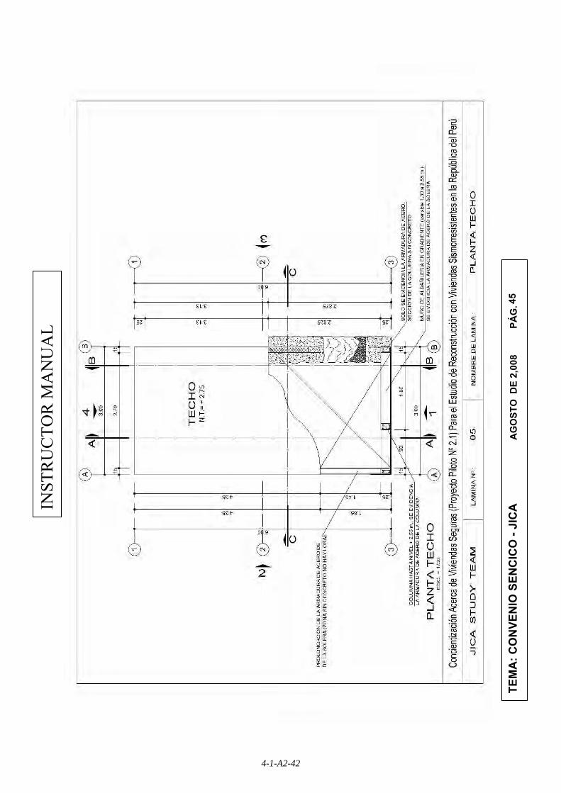
45
INST
RU
CTO
R M
AN
UA
L
TEM
A: C
ON
VEN
IO S
ENC
ICO
- JI
CA
A
GO
STO
DE
2,00
8
P
ÁG
.
4-1-A2-42

46
INST
RU
CTO
R M
AN
UA
L
TEM
A: C
ON
VEN
IO S
ENC
ICO
- JI
CA
A
GO
STO
DE
2,00
8
P
ÁG
.
4-1-A2-43

48
INST
RU
CTO
R M
AN
UA
L
TEM
A: C
ON
VEN
IO S
ENC
ICO
- JI
CA
A
GO
STO
DE
2,00
8
P
ÁG
.
4-1-A2-44

49
INST
RU
CTO
R M
AN
UA
L
TEM
A: C
ON
VEN
IO S
ENC
ICO
- JI
CA
A
GO
STO
DE
2,00
8
P
ÁG
.
4-1-A2-45

50
INST
RU
CTO
R M
AN
UA
L
TEM
A: C
ON
VEN
IO S
ENC
ICO
- JI
CA
A
GO
STO
DE
2,00
8
P
ÁG
.
4-1-A2-46

52
INST
RU
CTO
R M
AN
UA
L
TEM
A: C
ON
VEN
IO S
ENC
ICO
- JI
CA
A
GO
STO
DE
2,00
8
P
ÁG
.
4-1-A2-47

53
INST
RU
CTO
R M
AN
UA
L
TEM
A: C
ON
VEN
IO S
ENC
ICO
- JI
CA
A
GO
STO
DE
2,00
8
P
ÁG
.
4-1-A2-48

54
INST
RU
CTO
R M
AN
UA
L
TEM
A: C
ON
VEN
IO S
ENC
ICO
- JI
CA
A
GO
STO
DE
2,00
8
P
ÁG
.
4-1-A2-49
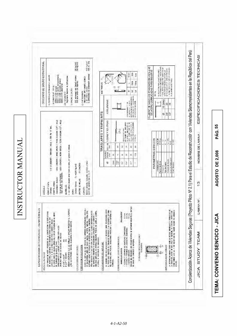
55
INST
RU
CTO
R M
AN
UA
L
TEM
A: C
ON
VEN
IO S
ENC
ICO
- JI
CA
A
GO
STO
DE
2,00
8
P
ÁG
.
4-1-A2-50

Appendix 3
Participant Textbook
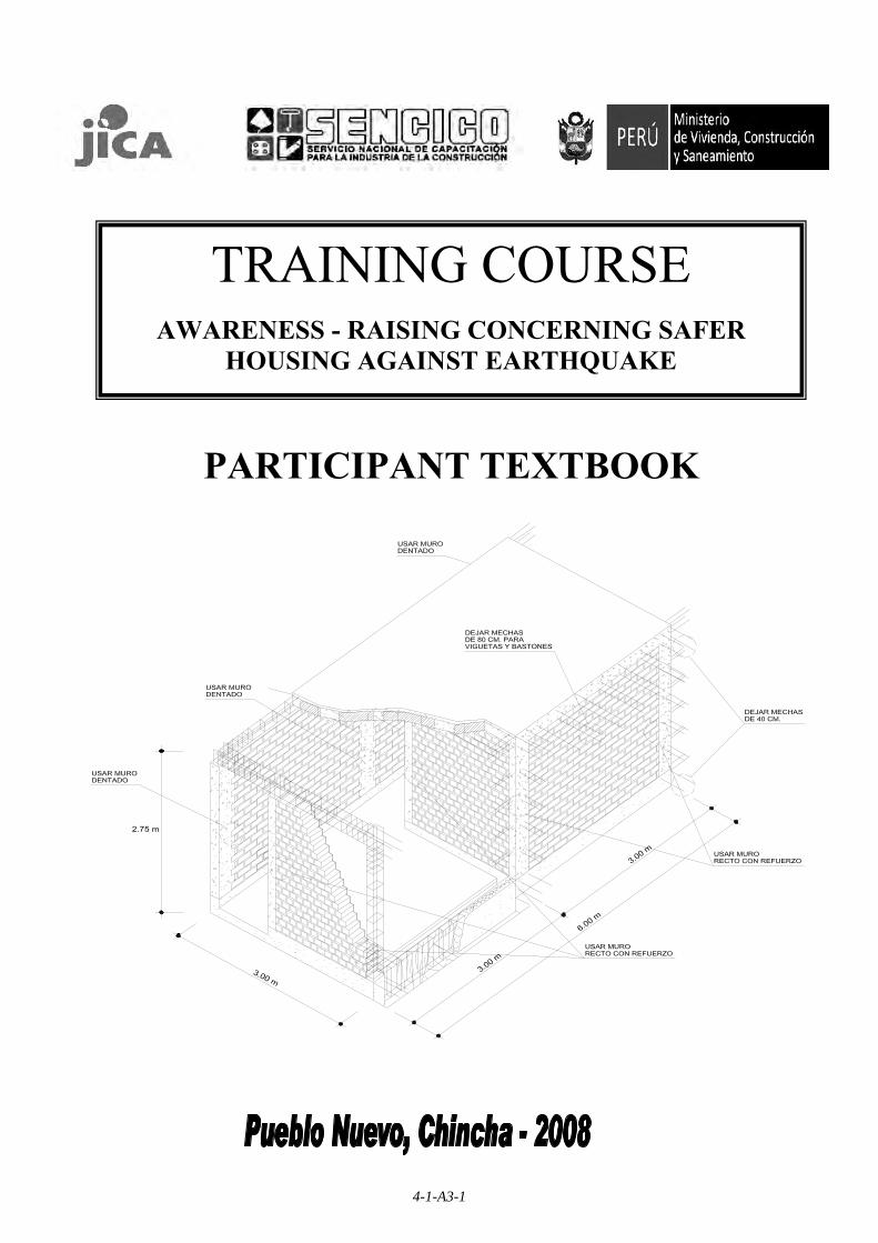
TRAINING COURSE
AWARENESS - RAISING CONCERNING SAFER HOUSING AGAINST EARTHQUAKE
PARTICIPANT TEXTBOOK
4-1-A3-1

JICA STUDY TEAM 2 SENCICO ICA
PARTICIPANT TEXTBOOK
WORK TEAM
JICA STUDY TEAM
Ichiro Kobayashi Team Leader
Kyoichi Sugiyama Seismic Resistant Structure Specialist
Takatsugu Shimada Construction Manager
Eng. Gustavo Quijada Seismic Resistant Structure Specialist
Miguel Alemán Translator
SENCICO ICA Ing. Juan Cajachagua
Castillo Gerente Zonal de Sencico
Econ. Juan López Arias.
Especialista Educativo
Ing. Carlos Condorchoa C. Promotor Educativo
Inst. Marco Condorchoa
Camacho
This Participant Textbook has been prepared by JICA and SENCICO with the technical and financial cooperation of the Government of Japan.
4-1-A3-2

JICA STUDY TEAM 3 SENCICO ICA
PARTICIPANT TEXTBOOK
OBJECTIVE The objective of this participant textbook is to teach ordinary people the most important necessary knowledge (minimum requirements) to build a seismic resistant safer house.
Minimum Requirements
• Quality of materials
• Structural section of main members
• Conection of structural elements
Cement Sand Crushed Water stone ½”
4-1-A3-3

JICA STUDY TEAM 4 SENCICO ICA
PARTICIPANT TEXTBOOK
INDEX
1. CHRONOGRAM …………………………………………………………………5
2. CONSTRUCTIVE PROCESS…………………………………………………..8
Chapter 1 Knowing your land and reading the drawings ……………….9
Chapter 2 Cleaning, Leveling and tracing on your land …..…………….10
Chapter 3 Excavating the Foundation ……………………….…….……...13
Chapter 4 Making framework for confined columns..……………………14
Chapter 5 Building the foundation………………………………………….17
Chapter 6 Making framework for reinforced tie beam..………………….19
Chapter 7 Making formwork for reinforced tie beam…..….………….…20
Chapter 8 Building the tie beam…………………………………………...21
Chapter 9 Installing the first brick row…………………………………….23
Chapter 10 Building the walls.………………………………………………24
Chapter 11 Making and filling the confined columns …………………….27
Chapter 12 Making the ring beams formworks.…………………………..30
Chapter 13 Making the ring beams frameworks..………………………...31
Chapter 14 Making the light slab formworks.……………………………..33
Chapter 15 Making light slab frameworks…………………………………35
Chapter 16 Building the light slab...………….…………………………….37
3. MINIMUM REQUIREMENTS (ANNEX 1).…….……………………………40
4. DRAWINGS (ANNEX 2) ……………………………………………………..44
5. BIBLIOGRAPHY.………………………………………………………………62
4-1-A3-4

JICA STUDY TEAM 5 SENCICO ICA
PARTICIPANT TEXTBOOK
1. CHRONOGRAM
4-1-A3-5
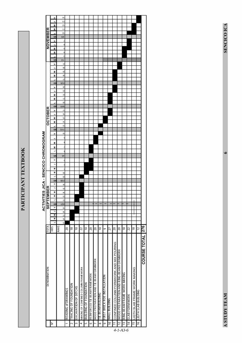
A S
TU
DY
TE
AM
6
SEN
CIC
O IC
A
PAR
TIC
IPA
NT
TE
XT
BO
OK
Nº
HRS
LM
MJ
V
S/D
LM
MJ
V
S/D
LM
MJ
V
S/D
LM
MJ
V
S/D
LM
MJ
V
S/D
LM
MJ
V
S/D
LM
MJ
V
S/D
LM
MJ
V
S/D
LM
MJ
V
AAAS
15
16
17
18
19
20/21
22
23
24
25
26
27/28
29
30
1
2
3
4/5
6
7
8
9
10
11/12
13
14
15
16
17
18/19
20
21
22
23
24
25/26
27
28
29
30
31
1/2
3
4
5
6
7
8/9
10
11
12
13
14
1RE
ADIN
G o
f DRA
WIN
GS
202
TRAC
ING
OF
FOUN
DATI
ON
183
EXCA
VATI
ON
OF
DITC
HS
104
MAK
ING
OF
CONF
INED
CO
LUM
N FR
AMEW
ORK
225
BUIL
DING
OF
FOUN
DATI
ON
106
REIN
FORC
ED T
IE B
EAM
FRA
MEW
ORK
207
WO
OD
PREP
ARAT
ION
AND
TIE
BEAM
FO
RMW
ORK
208
TIE
BEAM
BUI
LDIN
G10
9FI
RST
BRIC
K RO
E IN
STAL
LATI
ON
910
WAL
L BU
ILDI
NG27
11C
ON
FIN
ED
CO
LUN
M F
OR
MW
OR
K A
ND
MIX
PO
UR
ING
2012
WO
OD
PREP
ARAT
ION
AND
RING
BEA
M F
ORM
WO
RK20
13RI
NG B
EAM
FRA
ME
WO
RK M
AKIN
G18
14SL
AB F
ORM
WO
RK22
15LI
GT
H S
LAB
FR
AM
E W
OR
K M
AK
ING
1816
LIG
TH S
LAB
BUIL
DING
12 276
NO
VE
MB
ER
AC
TIV
ITIE
S J
ICA
- S
EN
CIC
O C
HR
ON
OG
RA
M
COUR
SE T
OTA
L
DENO
MIN
ATIO
NTO
TA LS
EP
TE
MB
ER
OC
TO
BE
R
4-1-A3-6

ICA STUDY TEAM 7 SENCICO ICA
PARTICIPANT TEXTBOOK
OBJECTIVE
• Quality of materials
• Structural section of main members
• Conection of structural elements
The objective of the participant textbook is to teach ordinary people the necessary knowledge (minimum requirements) to build a safer house
cemento arena piedra agua chancada 1/2”
MINIMUM REQUIREMENTS
4-1-A3-7

ICA STUDY TEAM 8 SENCICO ICA
PARTICIPANT TEXTBOOK
2.CONSTRUCTIVE PROCESS
4-1-A3-8
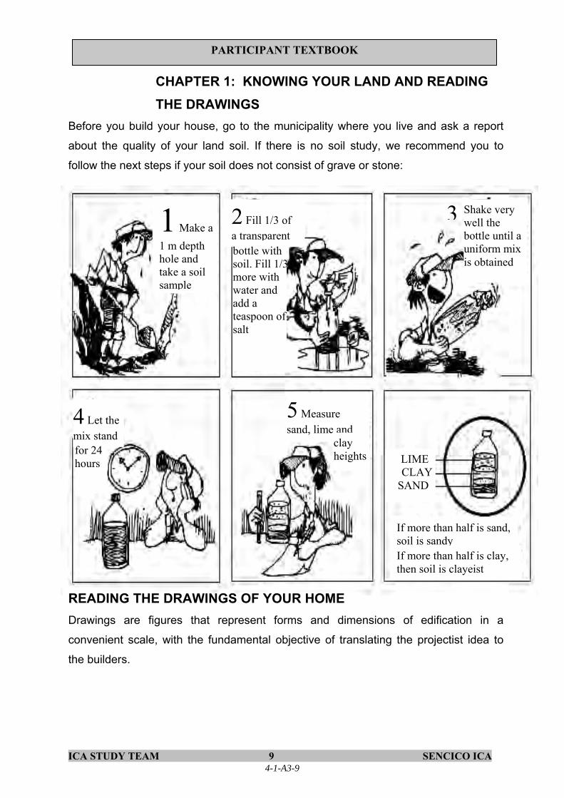
ICA STUDY TEAM 9 SENCICO ICA
PARTICIPANT TEXTBOOK
CHAPTER 1: KNOWING YOUR LAND AND READING THE DRAWINGS
Before you build your house, go to the municipality where you live and ask a report
about the quality of your land soil. If there is no soil study, we recommend you to
follow the next steps if your soil does not consist of grave or stone: READING THE DRAWINGS OF YOUR HOME Drawings are figures that represent forms and dimensions of edification in a
convenient scale, with the fundamental objective of translating the projectist idea to
the builders.
1 Make a 1 m depth hole and take a soil sample
2 Fill 1/3 of a transparent bottle with soil. Fill 1/3more with water and add a teaspoon of salt
Shake very well the bottle until a uniform mix is obtained
4 Let the mix stand for 24 hours
5 Measure sand, lime and
clay heights LIME
CLAY SAND
If more than half is clay, then soil is clayeist
If more than half is sand, soil is sandy
3
4-1-A3-9

ICA STUDY TEAM 10 SENCICO ICA
PARTICIPANT TEXTBOOK
CHAPTER 2: CLEANING, LEVELLING AND TRACING OF LAND 2.1 CLEANING THE LAND
It involves the elimination of garbage
or free elements, light and heavy
present on the land surface destined
for building, as well as the extraction
of roots and small trees.
2.2 DETERMINING OF LEVEL
All the land should be at the same level and to get this follow the next steps:
Fill the hose with clean water and verify the absence of bubles.
Check the exactness and functioning joining both hose ends and verifying that water is at the same height.
Place stakes in the borders of the land and verify that they are vertical using a plumb.
With the help of a stake identify a reference point i.e. the pavement and mark on the stake a height of 1 m above the reference level.
With the help of the hose, bring the mark of the first stake to the other stakes.
Organic soil is bad for
construction
Use 1.5 m heigh stakes
Use a ½” diameter transparent hose, maximum 10 m long
4-1-A3-10

ICA STUDY TEAM 11 SENCICO ICA
PARTICIPANT TEXTBOOK
2.3 CUTTING AND REFILLING
a) After marking all the stakes, measure in every stake the height between the mark and the natural soil.
Refilling
when the measure is longer than 1 m
Cutting When the measure is less than 1 m
b) Refill and/or cut the land until the height between the mark and the soil is 1 m
Cutting level
Cord Level point
Level point
Refilling
Natural land
4-1-A3-11

ICA STUDY TEAM 12 SENCICO ICA
PARTICIPANT TEXTBOOK
2. 4 TRACING
Tracing is useful to indicate in the land where the foundation of your house is
going to be built. Prepare several balizes with wood sticks.
According to the BALIZE measures indicated in the drawing, place the balizas on the land, so that they correspond to the foundation sides.
Determine the center of each foundation and install cords between balizas to define the foundation width.
Graphic method to find a 90° angle
Use the cords as guides and mark in the soil the foundation width with chalk or lime.
4-1-A3-12

ICA STUDY TEAM 13 SENCICO ICA
PARTICIPANT TEXTBOOK
CHAPTER 3: EXCAVATING THE FOUNDATION MINIMUM REQUIREMENTS
2.0 Structural Section of Main Members 2.1. Foundation
Foundation width and height are 60 cm or more. Foundation depth is no less than 80 cm.
Leyend
80 cm 50 cm F.B.L : Foundation bottom level F.B.L N.L.L : Natural Land Level
F.S.L : Floor Slab Level
60 cm
If the soil at the ditch
bottom is difficult to level,
it is possible to input a
poor concrete mix (1:12)
for the bottom of the ditch
in order to have it leveled
N.L.L F.S.L = +0.10
Ditch excavation Excavate foundation ditch using chalk marks as guides
Ditch sides should be as vertical as possible
Bottom should be levelled, clean and without soil powder
Ditches should beclean and organic compounds free
4-1-A3-13

ICA STUDY TEAM 14 SENCICO ICA
PARTICIPANT TEXTBOOK
CHAPTER 4: MAKING CONFINED COLUMN MINIMUM REQUIREMENTS 2.0 Structural Section of Main Members 2.2 Sections of RC concrete member
c) Column has a minimum section of 13 cm wide and 15 cm high, and four (4) steel bars of 3/8”diameter are placed with hoops of 1/4” diameter. Five (5) hoops are placed from the connection point with tie beam. First hoop is placed at 5 cm from the connection point. The other four (4) hoops above the first hoop are placed at 10 cm interval. Another five (5) hoops are placed from the point with ring beam as the same case from the connection of tie beam. At the rest space of column hoops are placed at 25 cm interval. Additionally, two (2) stirrups are placed in joint of column and ring beam at 10 cm interval. Two (2) stirrups are also placed in joint of column and tie beam at 10 cm interval.
3.0 Conection of Structural Members 3.1 Anchor of column to reinforced tie beam and ring beam
Four (4) steel bars of column anchor to the foundation. The steel bars bend 90° at 75 mm from the bottom of foundation. The bended steel bars are prolonged 25 cm. In order to connect steel bars of column and tie beam, additional four (4) steel bars connect with each column bar that anchors to the foundation. The additional bars bend 90° at 40 mm from the bottom of tie beam. The bended steel bars are prolonged 25 cm measured from the column surface. In case of good soil, concrete without reinforcement is used and the four (4) steel bars of column anchor to the foundation. In the same way, four (4) steel bars of column anchor to reinforced ring beam. The steel bars bend 90° at 20 mm from the top of ring beam. The bended steel bars are prolonged 25 cm measured from the column surface.
3.3 Overlapping of reinforcements. Steel bars of reinforced concrete overlap at least at 40 cm.
4.1 PREPARING THE FRAMEWORK OF THE CONFINED COLUMN
To prepare a column, observe the indicated minimum requirements.
4 Ø 3/8” Hoops ¼”
Columns have 4 steel bars of at least 3/8”. Column hoops are of ¼” and are installed with the following spacement 1 @ 5 cm + 4 @ 10 cm + the others @ 25 cm, in each end
THE FRAMEWORK
Try to install the bended part of the hoop in alternated position and never on the same column corner
4-1-A3-14

ICA STUDY TEAM 15 SENCICO ICA
PARTICIPANT TEXTBOOK
4.2 PREPARING THE HOOPS
Hoops are made with steel bars of ¼”
Hoops distribution
Legend T.B.U.L: Tie beam upper level
T.B.L.L: Tie beam lower level
F.S.L: Floor slab level
F.L. L:Foundation lower level
How to install hoops in column frameworks
Bending of hoops
Correct Incorrect
It is very important that ganchos are finally presented toward the inner side of the columnso that it works well during the earthquake
T.B.U.L
T.B.L.L
F.S.L
F.L.L=
Steel bending usually applied in foundation
Col
umn
pour
ing
heig
ht
Slab
HOOPS
4-1-A3-15
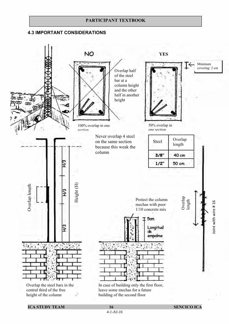
ICA STUDY TEAM 16 SENCICO ICA
PARTICIPANT TEXTBOOK
4.3 IMPORTANT CONSIDERATIONS
Minimum covering: 2 cm
Overlap half of the steel bar at a column height and the other half in another height
YES
100% overlap in one section
50% overlap in one section
Never overlap 4 steel on the same section because this weak the column
Steel Overlap length
Hei
ght (
H)
Ove
rlap
leng
th
Protect the column mechas with poor 1/10 concrete mix
Overlap the steel bars in the central third of the free height of the column
In case of building only the first floor, leave some mechas for a future building of the second floor
Join
t with
wir
e #
16
Ove
rlap
leng
th
4-1-A3-16

ICA STUDY TEAM 17 SENCICO ICA
PARTICIPANT TEXTBOOK
CHAPTER 5: BUILDING FOUNDATION MINIMUM REQUIREMENTS
1.0 Quality of materials
1.3. Foundation a) Mixture design for foundation is one (1) portion of Portland cement, ten
(10) portions of hormigon, one and half (1.5) portions of water and three (3) portions of large stones (the size is maximum 10”). Hormigon is composed of gravel and coarse sand directly obtained from quarry place.
1.6. Water a) Water is clean and drinkable
2.0 Structural Section of Main Members 2.2 Sections of reinforced concrete member
a) Minimum covering depth of concrete is 20 mm for walls with finish and 30 mm for walls without finish. In case of foundation, covering depth is 75 mm.
For foundation we use Cyclops concrete, which has the following dossification:
1 10 3 1.5 CEMENT HORMIGON LARGE STONE WATER
Ditch wetting First, ditch is wetted before
addition of foundation concrete.
4-1-A3-17

ICA STUDY TEAM 18 SENCICO ICA
PARTICIPANT TEXTBOOK
5.1 POURING MIX IN THE FOUNDATION With the help of one-wheel chart or
buggies pour concrete in the
foundation. While you are doing this
addition, throw large stones on the
ditch. Don’t put large stones near
columns frameworks, and leave
about 30 cm of every side of the
column without large stones.
Be careful that every stone is completely
covered with concrete.
Draw lines on the surface so that tie beam could adhere better
N.L.L
Finally, foundation will finish like this
60 cm
Natural Land
Foundation
4-1-A3-18

ICA STUDY TEAM 19 SENCICO ICA
PARTICIPANT TEXTBOOK
CHAPTER 6: MAKING FRAMEWORK FOR REINFORCED TIE BEAM MINIMUM REQUIREMENTS 2. Structural Section of Main Members
2.2. Sections of reinforced concrete member a) Tie beam width is 13 cm or 24 cm according to the width of the wall. The
minimum height is 50 cm. Tie beam is reinforced with four (4) steel bars of 3/8” diameter, with stirrups of 1/4” diameter at 20 cm intervals. If the soil is mainly composed of slime and/or sand, the tie beam is needed to be reinforced.
6.1 STEEL REINFORCEMENT IN TIE BEAM When the soil of your land is sandy or limy, it is better to put reinforcement steel in tie beam.
Armadura Mínima 4 Ø 3/8” 6.2 TIE BEAM WITHOUT REINFORCEMENT
Stirrups of If your land has rocky or gravely soil, it does not need ¼” every 20 cm reinforcement in the tie beam. 13 cm
13 cm. Reinforced Tie beam without
tie beam reinforcement
50.cm 50 cm.
60
º
60 cm.
80 cm
80 cm.
Minimum framework 4 steel bar (3/8”)
4-1-A3-19

ICA STUDY TEAM 20 SENCICO ICA
PARTICIPANT TEXTBOOK
CHAPTER 7: MAKING FORMWORK FOR REINFORCED TIE BEAM MINIMUM REQUIREMENTS 1.0. Quality of materials
1.4. Wood a) Wood is hard, dry, dense fiber, well cured, no crack and straight. 7.1 PREPARING FORMWORK IN THE TIE BEAM 1. Tie beam is traced according to the
dimensions of the brick wall. Use a marker to mark the line on the foundation.
2.- Wood (yard lumber) are aligned and
secured with vertical steel stakes all the line.
3.- Dormants are installed
and secured on both sides with steel stakes every 50 cm. Vertical wood stake joints with dormant through a diagonal wood stake. By means of a plumb, required verticality is obtained using a cord in both ends of formwork.
WOOD STAKE DORMANT STEEL STAKE YARD LUMBER
4-1-A3-20

ICA STUDY TEAM 21 SENCICO ICA
PARTICIPANT TEXTBOOK
CHAPTER 8: BUILDING THE TIE BEAM
MINIMUM REQUIREMENTS:
1.0 Quality of materials 1.6. Concrete
a) Mixture design for reinforced tie beam is one (1) portion of Portland cement, two (2) portions of clean coarse sand, four (4) portions of crushed stone (the size is less than 1/2”) and one (1) portion of clean and drinkable water.
b) Materials are well mixed where the aggregate is not visible and poured to form work immediately.
c) Form work is hard and no bleeding. d) Any gaps and void is avoided by using a stick to compact concrete when it
is pouring. 8.1 REINFORCED TIE BEAM. Mixture design is: 1 2 4 1
CEMENT COARSE SAND CRUSHED STONE WATER NOTE You can mix by hand the concrete for tie beams. Clean a plane zone for mixing, preferably on a concrete floor. Mix dry materials and then add water.
.
When the tie beam mix pouring is over, mark lines with a nail in order that the first raw of bricks can fix well.
Reinforced tie beam
N.L.L
Construction joint
If you need to stop found-ation or tie beam pouring, lefa diagonal joint with outstanding stones
4-1-A3-21

ICA STUDY TEAM 22 SENCICO ICA
PARTICIPANT TEXTBOOK
8.1 TIE BEAM WITHOUT REINFORCEMENT Mixture design is: 1 8 2.5 1.25
Cement Hormigon Medium Stone Water Tie beam without reinforcement
When the tie beam mix pouring is over, mark lines with a nail in order that the first raw of bricks can fix well.
4-1-A3-22

ICA STUDY TEAM 23 SENCICO ICA
PARTICIPANT TEXTBOOK
CHAPTER 9: INSTALLING THE FIRST BRICK ROWS OF THE WALL
MINIMUM REQUIREMENTS:
1.0 Quality of materials
1.5. Brick. a) Brick is burned and orange color without white pale shadow. Brick is also
dust free, without cracks or bending. 3.0 Connection of structural elements 3.4 Wall joint mortar thickness Thickness of joint mortar for wall is from 1.0 to 1.5 cm.
9.1 INSTALLING THE FIRST BRICK ROWS Before the beginning of brick installation, show
them in dry (without mortar) the first two brick
rows; vertical joints uniformity is checked and
solutions of intersections and joints between the
wall and confined columns.
FIRST ROW SECOND ROW
REMEMBER:
Prepare a Escantillon (vertical
brick layer distribution ruler) to fix
the height of the vertical joint
between 1 y 1.5 cm.
Brick height
Joint thick
Vertical Joints Wood spacer
Row height
4-1-A3-23

ICA STUDY TEAM 24 SENCICO ICA
PARTICIPANT TEXTBOOK
CHAPTER 10: BUILDING THE WALL MINIMUM REQUIREMENTS:
1.0 Quality of materials. 1.2 Mortar
a) Mixture design is one (1) portion of Portland cement and four (4) portions of clean coarse sand.
1.5 Brick a) Brick is baked and orange color without white pale shadow. Brick is also dust
free, without cracks or bending. 1.6. Water a) Water is clean and potable.
2.0 Structural Section of Main Members Wall of confined masonry house is enclosed firmly with reinforced concrete tie beam, reinforced concrete column and reinforced concrete ring beam on a stable foundation with enough strength. Every vertical part of wall corner is firmly connected, forming confined elements.
2.2 Sections of reinforced concrete member b) Maximum wall area framed with tie beam, column and ring beam is 12.0 m2.
The maximum height of the wall is 2.4 m. 10.1 Mix design for building a wall is:
1 4
CEMENT FINE SAND Wet the upper part of the tie beam with a poor cement mix
Brick Preparation One day before the building of wall, clean the bricks, wet them with water for 20 minutes and then let them repose
4-1-A3-24

ICA STUDY TEAM 25 SENCICO ICA
PARTICIPANT TEXTBOOK
10.2 INSTALLING BRICKS Install bricks in the final position they
are going to be placed, joint to others
with mortar, forming rows and
keeping the joints alterned and
uniform.
10.3 PLUMBING Verify, in every row, the verticality of the wall with the plumb. REMEMBER: The vertical and horizontal joint is from 1.0 to 1.5 cm, do not do wider or higher points because the wall is weakened.
4-1-A3-25

ICA STUDY TEAM 26 SENCICO ICA
PARTICIPANT TEXTBOOK
MINIMUM REQUIREMENTS: 3.0. Structural elements conection
3.2. Wall – Column Conection. There are two connection methods. One is that joint between wall and
columns is geared and the length of the salient part of brick does not exceed 5 cm. The other is that two (2) steel bars of 1/4” diameter anchor at every four (4) layers of wall bricks at least 40 cm inside masonry and 12.5 cm inside column with vertical turning of 90° at 10 cm.
2 Ø 1/4" CADA 4 HILADAS
Wall
Reinforced tie beam
Foundation
WALL-COLUMN DENTED CONNECTION DETAIL
Every 4 rows
WALL-COLUMN RASING CONNECTION DETAIL
4-1-A3-26
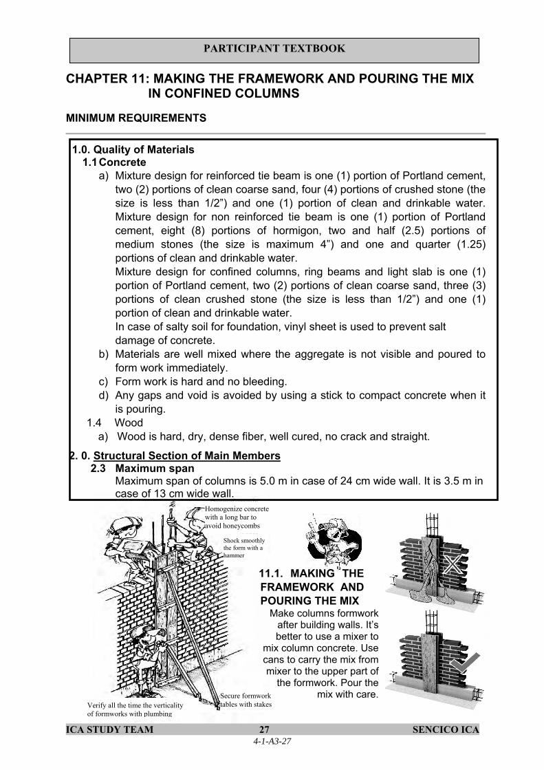
ICA STUDY TEAM 27 SENCICO ICA
PARTICIPANT TEXTBOOK
CHAPTER 11: MAKING THE FRAMEWORK AND POURING THE MIX IN CONFINED COLUMNS
MINIMUM REQUIREMENTS
1.0. Quality of Materials 1.1 Concrete
a) Mixture design for reinforced tie beam is one (1) portion of Portland cement, two (2) portions of clean coarse sand, four (4) portions of crushed stone (the size is less than 1/2”) and one (1) portion of clean and drinkable water. Mixture design for non reinforced tie beam is one (1) portion of Portland cement, eight (8) portions of hormigon, two and half (2.5) portions of medium stones (the size is maximum 4”) and one and quarter (1.25) portions of clean and drinkable water. Mixture design for confined columns, ring beams and light slab is one (1) portion of Portland cement, two (2) portions of clean coarse sand, three (3) portions of clean crushed stone (the size is less than 1/2”) and one (1) portion of clean and drinkable water. In case of salty soil for foundation, vinyl sheet is used to prevent salt damage of concrete.
b) Materials are well mixed where the aggregate is not visible and poured to form work immediately.
c) Form work is hard and no bleeding. d) Any gaps and void is avoided by using a stick to compact concrete when it
is pouring. 1.4 Wood
a) Wood is hard, dry, dense fiber, well cured, no crack and straight.
2. 0. Structural Section of Main Members 2.3 Maximum span
Maximum span of columns is 5.0 m in case of 24 cm wide wall. It is 3.5 m in case of 13 cm wide wall.
11.1. MAKING THE FRAMEWORK AND POURING THE MIX
Make columns formwork after building walls. It’s better to use a mixer to
mix column concrete. Use cans to carry the mix from mixer to the upper part of
the formwork. Pour the mix with care.
Homogenize concrete with a long bar to avoid honeycombs
Shock smoothly the form with a hammer
Secure formwork tables with stakes Verify all the time the verticality
of formworks with plumbing
4-1-A3-27

ICA STUDY TEAM 28 SENCICO ICA
PARTICIPANT TEXTBOOK
Mix design for confined column is:
1 2 3 1
CEMENT SAND CRUSHED STONE WATER
11.2 CONCRETE MIX MIX ADD WATER TOO MUCH LIQUID GOOD
4-1-A3-28

ICA STUDY TEAM 29 SENCICO ICA
PARTICIPANT TEXTBOOK
11.3 TAKING OUT THE FORMWORK
After pouring the concrete in the confinement columns, let the formwork in its place for 24 hours, then take out them and use them again for other columns.
Each element is cured at least for 7days
Curing Cure the concrete after taking out the columns formwork. Curing consist of adding water to concrete elements three times every day for better concrete hardening
4-1-A3-29
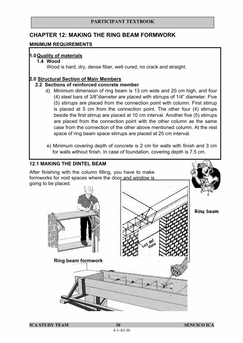
ICA STUDY TEAM 30 SENCICO ICA
PARTICIPANT TEXTBOOK
CHAPTER 12: MAKING THE RING BEAM FORMWORK MINIMUM REQUIREMENTS
1.0 Quality of materials
1.4 Wood Wood is hard, dry, dense fiber, well cured, no crack and straight.
2.0 Structural Section of Main Members
2.2 Sections of reinforced concrete member d) Minimum dimension of ring beam is 13 cm wide and 20 cm high, and four
(4) steel bars of 3/8”diameter are placed with stirrups of 1/4” diameter. Five (5) stirrups are placed from the connection point with column. First stirrup is placed at 5 cm from the connection point. The other four (4) stirrups beside the first stirrup are placed at 10 cm interval. Another five (5) stirrups are placed from the connection point with the other column as the same case from the connection of the other above mentioned column. At the rest space of ring beam space stirrups are placed at 25 cm interval.
e) Minimum covering depth of concrete is 2 cm for walls with finish and 3 cm for walls without finish. In case of foundation, covering depth is 7.5 cm.
12.1 MAKING THE DINTEL BEAM After finishing with the column filling, you have to make formworks for void spaces where the door and window is going to be placed.
Ring beam formwork
Ring beam
4-1-A3-30

ICA STUDY TEAM 31 SENCICO ICA
PARTICIPANT TEXTBOOK
CHAPTER 13: MAKING THE FRAMEWORK FOR RING BEAM MINIMUM REQUIREMENTS 2.0 Structural Section of Main Members
2.2 Sections of reinforced concrete member d) Minimum dimension of ring beam is 13 cm wide and 20 cm high, and four
(4) steel bars of 3/8”diameter are placed with stirrups of 1/4” diameter. Five (5) stirrups are placed from the connection point with column. First stirrup is placed at 5 cm from the connection point. The other four (4) stirrups beside the first stirrup are placed at 10 cm interval. Another five (5) stirrups are placed from the connection point with the other column as the same case from the connection of the other above mentioned column. At the rest space of ring beam space stirrups are placed at 25 cm interval.
3.0 Connection of Structural Members 3.1 Anchor of column to tie beam and ring beam
a) Four (4) steel bars of column anchor to the foundation. The steel bars bend 90° at 7.5 cm from the bottom of foundation. The bended steel bars are prolonged 25 cm. In order to connect steel bars of column and tie beam, additional four (4) steel bars connect with each column bar that anchors to the foundation. The additional bars bend 90° at 4 cm from the bottom of tie beam. The bended steel bars are prolonged 25 cm measured from the column surface. In case of good soil, concrete without reinforcement is used and the four (4) steel bars of column anchor to the foundation. In the same way, four (4) steel bars of column anchor to reinforced ring beam. The steel bars bend 90° at 2 cm from the top of ring beam. The bended steel bars are prolonged 25 cm measured from the column surface.
13.1 RING BEAMS Ring beams are important because they help to confine walls. Ring beams are placed over the walls.
Never stop concrete pouring in ring beams!
Minimum reinforcement The mínimum reinforcement for all types of beams is: four 3/8” steel bar for main framework; ¼” stirrups are placed in each end one at 5 cm, 4 at 10 cm and the rest at 25 cm.
Light slab thickness
Wall width
4-1-A3-31

ICA STUDY TEAM 32 SENCICO ICA
PARTICIPANT TEXTBOOK
13.2 JOINING THE TIE BEAM AND RING BEAM WITH THE COLUMN Place with care the frameworks in the joints of beams and columns. When filling these parts with concrete avoid gaps by using a steel bar.
Tie the steels with wire #16 in the joints of tie/ring beams and columns
In case the tie/ring beam doesn’t continue, bend the steel in a horizontal way
The length of the bending of the reinforcement steel tie/ring beams should be 25 cm
Ring/Tie beams spaciators For keeping the ring/tie beams steels in horizontal position, put below them mortar cubes of 2 cm side.
Distance between mortar cubes approximately1.5 m
MORTAR CUBE
Use mortar with
Wire# 16 for steelholding
Longitudinalframework
4-1-A3-32

ICA STUDY TEAM 33 SENCICO ICA
PARTICIPANT TEXTBOOK
CHAPTER 14: MAKING THE LIGHT SLAB FORMWORK MINIMUM REQUIREMENTS
1. Quality of Materials c) Form work is hard and no bleeding. 1.4 Wood a) Wood is hard, dry, dense fiber, well cured, no crack and straight.
14.1 FIXING THE BOTTOM OF SMALL BEAM
Mark the axis of small beams
Bottom of small beam
14.2 SECURING THE RIGHT FEET Beams Determine the place where right feet are going to be.
Yard lumber for securing right feet
Right foot
4-1-A3-33

ICA STUDY TEAM 34 SENCICO ICA
PARTICIPANT TEXTBOOK
14.2 INSTALLING THE BRICKS ON THE ROOF a. Locate the axis of small beams b. Place bricks with holes so that they
are in parallel to the woods Build the formwork for the slab with lumber yard of at least 1inch thickness, for the bottoms of small beams. Said woods are supported on lumber of 2” thick x 3” width that are supported by vertical sticks of 2” x 3” thick x 3” width.
bottom
Lumber beam
Vertical sticks of 2” x 3”
Brick or table
NO YES
Slab
Never put the light slab formwork over soil without compacting
It’s advisable to build slab before installing the light slab formwork. If there isn’t a slab, soil should be very well compacted and leveled.
4-1-A3-34

ICA STUDY TEAM 35 SENCICO ICA
PARTICIPANT TEXTBOOK
CHAPTER 15: MAKING THE FRAMEWORK FOR LIGTH SLAB MINIMUM REQUIREMENTS 2.0. Structural Section of Main Members
2.2 Sections of reinforced concrete member d).Minimum dimension of ring beam is 13 cm wide and 20 cm high, and four (4)
steel bars of 3/8”diameter are placed with stirrups of 1/4” diameter. Five (5) stirrups are placed from the connection point with column. First stirrup is placed at 5 cm from the connection point. The other four (4) stirrups beside the first stirrup are placed at 10 cm interval. Another five (5) stirrups are placed from the connection point with the other column as the same case from the connection of the other above mentioned column. At the rest space of ring beam space stirrups are placed at 25 cm interval.
Ligth slab componentsLigth slabs are formed by small beams separated at 40 cm from axis to axis. Between beam and beam light bricks 30 cm wide 15 cm high are placed. A 5 cm thick concrete is poured on the upper part.
Use 20 cm thick light slab for up to 4.5m long roofing. Small ring beams directions follow the shortest space to roof
Upper light slab
Roof brick
Temperature steel
Upper steelLower steel
4-1-A3-35

ICA STUDY TEAM 36 SENCICO ICA
PARTICIPANT TEXTBOOK
Components dimensions
Roof bricks should be perfectly aligned and the slight slab should also be very well leveled.
Roof brick Upper steel Temperature steel Upper slab
Small beam
Small beams don’t need hoops
Temperature steel To avoid that upper slight slab cracks due to temperatura effect, ¼” steel bars are placed perpendicularly to the small beams every 25 cm.
Temperature steel is placed i the center of the upper light slab
Prepare 2 cm side cubes and use them to support the small beam steel
2 cm side cubes
Minimum covering = 2 cm Lower steel
NO! Steel temperature should not be in contact with the roof brick.
Overlaps of small beams reinforce If you need to overlap the lower steel (positive) ofthe smalll beam, do the overlaps in the third partof the bar end.
Steel Overlapping length
3/8” 40 cm 1/2" 50 cm
Never overlap the lower steel in the center of small beam
Overlap the lower steel in the end third
Overlap length
YES
Length/3 Length/3 Length/3
Length
4-1-A3-36

ICA STUDY TEAM 37 SENCICO ICA
PARTICIPANT TEXTBOOK
CHAPTER 16: BUILDING LIGHT SLAB MINIMUM REQUIREMENTS 1.0 Quality of Materials
1.1 Concrete a) Mixture design for confined columns, ring beams and light slab is one (1)
portion of Portland cement, two (2) portions of clean coarse sand, three (3) portions of clean crushed stone (the size is less than 1/2”) and one (1) portion of clean and drinkable water. In case of salty soil for foundation, vinyl sheet is used to prevent salt damage of concrete.
b) Materials are well mixed where the aggregate is not visible and poured to form work immediately.
c) Form work is hard and no bleeding. d) Any gaps and void is avoided by using a stick to compact concrete when it
is pouring. 16.1Previous work before pouring concrete in the slab
Install a wood table for walking on the roof formwork. Don’t walk on the bricks
To begin with light slab pouring, wet bricks and ring beam formwork.
Verify again the formworks horizontality and verify that right foot has not change in position or not being destabilized
4-1-A3-37

ICA STUDY TEAM 38 SENCICO ICA
PARTICIPANT TEXTBOOK
16.2 POURING CONCRETE IN SLABS AND RING BEAMS Mixture design for slab mix is:
1 2 3 1
CEMENT SAND CRUSHED STONE ½” WATER Fill the ligth slab and the ring beams at the same time because it is important that they work jointly. Fill the slab by sections. Begin filling the ring beam, then fill the small beams and finally the upper slab. It is better to hire a mixer machine for concrete mixing. This will help you reduce the slab filling time and will help some saving in materials.
It’s better to use a vibrator for light slab and ring beam concrete pouring. If not possible, homogenize carefully the concrete mix
Woodlumber
Use cans to carry concrete over from mixer to ring beam or light slab
Pour concrete mix with care. Avoid stepping on electricity or water pipes
During ring beam pouring knock the lateral side of the formwork to avoid concrete honey crumbs
4-1-A3-38

ICA STUDY TEAM 39 SENCICO ICA
PARTICIPANT TEXTBOOK
Light slab curing Light slab should be cured constantly. Curing must begin as soon as possible,do not wait from one day to other to begin it. Form closed spaces with sand cordons and fill them with water. Light slab should be cured for at least seven days.
Don’t do any work over the light slab for at least two days after concrete pouring.
Don’t wait more than one day to begin the curing
4-1-A3-39

ICA STUDY TEAM 40 SENCICO ICA
PARTICIPANT TEXTBOOK
3. MINIMUM REQUIREMENTS
(Annex 1)
4-1-A3-40

ICA STUDY TEAM 41 SENCICO ICA
PARTICIPANT TEXTBOOK
Minimum Requirements for Safer Housing
JICA Study Team 1. Quality of Materials 2. Structural Section of Main Members 3. Connection of Structural Members
1. Quality of Materials
1.1 Concrete a) Mixture design for reinforced tie beam is one (1) portion of Portland cement, two (2)
portions of clean coarse sand, four (4) portions of crushed stone (the size is less than 1/2”) and one (1) portion of clean and drinkable water. Mixture design for non reinforced tie beam is one (1) portion of Portland cement, eight (8) portions of hormigon, two and half (2.5) portions of medium stones (the size is maximum 4”) and one and quarter (1.25) portions of clean and drinkable water. Mixture design for confined columns, ring beams and light slab is one (1) portion of Portland cement, two (2) portions of clean coarse sand, three (3) portions of clean crushed stone (the size is less than 1/2”) and one (1) portion of clean and drinkable water. In case of salty soil for foundation, vinyl sheet is used to prevent salt damage of concrete.
b) Materials are well mixed where the aggregate is not visible and poured to form work immediately.
c) Form work is hard and no bleeding. d) Any gaps and void is avoided by using a stick to compact concrete when it is pouring.
1.2 Mortar a) Mixture design is one (1) portion of Portland cement and four (4) portions of clean
coarse sand. 1.3 Foundation
a) Mixture design for foundation is one (1) portion of Portland cement, ten (10) portions of hormigon, three (3) portions of large stones (the size is maximum 10”) and one and half (1.5) portions of clean and drinkable water. Hormigon is composed of gravel and coarse sand directly obtained from quarry place
1.4 Wood a) Wood is hard, dry, dense fiber, well cured, no crack and straight.
1.5 Brick a) Brick is baked and orange color without white pale shadow. Brick is also dust free,
without cracks or bending. 1.6 Water
a) Water is clean and drinkable. 2. Structural Section of Main Members
Wall of confined masonry house is enclosed firmly with reinforced concrete tie beam, reinforced concrete column and reinforced concrete ring beam on a stable foundation with
4-1-A3-41

ICA STUDY TEAM 42 SENCICO ICA
PARTICIPANT TEXTBOOK
enough strength. Every vertical part of wall corner is firmly connected, forming confined elements. 2.1 Foundation
Foundation width and height is 60 cm or more. Foundation depth is no less than 80 cm. 2.2 Sections of reinforced concrete member
a) Tie beam width is 13 cm or 24 cm according to the width of the wall. The minimum height is 50 cm. Tie beam is reinforced with four (4) steel bars of 3/8” diameter, with stirrups of 1/4” diameter at 20 cm intervals. If the soil is mainly composed of slime and/or sand, the tie beam is needed to be reinforced.
b) Maximum wall area framed with tie beam, column and ring beam is 12.0 m2. The maximum height of the wall is 2.4 m.
c) Column has a minimum section of 13 cm wide and 15 cm high, and four (4) steel bars of 3/8”diameter are placed with hoops of 1/4” diameter. Five (5) hoops are placed from the connection point with tie beam. First hoop is placed at 5 cm from the connection point. The other four (4) hoops above the first hoop are placed at 10 cm interval. Another five (5) hoops are placed from the point with ring beam as the same case from the connection of tie beam. At the rest space of column hoops are placed at 25 cm interval. Additionally, two (2) stirrups are placed in joint of column and ring beam at 10 cm interval. Two (2) stirrups are also placed in joint of column and tie beam at 10 cm interval.
d) Minimum dimension of ring beam is 13 cm wide and 20 cm high, and four (4) steel bars of 3/8”diameter are placed with stirrups of 1/4” diameter. Five (5) stirrups are placed from the connection point with column. First stirrup is placed at 5 cm from the connection point. The other four (4) stirrups beside the first stirrup are placed at 10 cm interval. Another five (5) stirrups are placed from the connection point with the other column as the same case from the connection of the other above mentioned column. At the rest space of ring beam space stirrups are placed at 25 cm interval.
e) Minimum covering depth of concrete is 2 cm for walls with finish and 3 cm for walls without finish. In case of foundation, covering depth is 7.5 cm.
f) Minimum length of structural wall is 1.2 m. 2.3 Maximum span
Maximum span of columns is 5.0 m in case of 24 cm wide wall. It is 3.5 m in case of 13 cm wide wall.
3. Connection of Structural Members
3.1 Anchor of column to tie beam and ring beam Four (4) steel bars of column anchore to the foundation. The steel bars bend 90° at 7.5 cm from the bottom of foundation. The bended steel bars are prolonged 25 cm. In order to connect steel bars of column and tie beam, additional four (4) steel bars connect with each column bar that anchores to the foundation. The additional bars bend 90° at 4 cm from the bottom of tie beam. The bended steel bars are prolonged 25 cm measured from the column surface. In case of good soil, concrete without reinforcement is used and the four (4) steel bars of column anchore to the foundation.
4-1-A3-42

ICA STUDY TEAM 43 SENCICO ICA
PARTICIPANT TEXTBOOK
In the same way, four (4) steel bars of column anchore to reinforced ring beam. The steel bars bend 90° at 2 cm from the top of ring beam. The bended steel bars are prolonged 25 cm measured from the column surface.
3.2 Connection of wall and column There are two connection methods. One is that joint between wall and columns is geared and the length of the salient part of brick does not exceed 5 cm. The other is that two (2) steel bars of 1/4” diameter anchor at every four (4) layers of wall bricks at least 40 cm inside masonry and 12.5 cm inside column with vertical turning of 90° at 10 cm.
3.3 Overlapping of reinforcements Steel bars of reinforced concrete overlap at least at 40 cm.
3.4 Wall joint mortar thickness Thickness of joint mortar for wall is from 1.0 to 1.5 cm.
4-1-A3-43

JIC
A S
TU
DY
TE
AM
48
SE
NC
ICO
ICA
PAR
TIC
IPA
NT
TE
XT
BO
OK
4.
Dra
win
gs
4-1-A3-44

JIC
A S
TU
DY
TE
AM
49
SE
NC
ICO
ICA
PAR
TIC
IPA
NT
TE
XT
BO
OK
AW
AR
EN
ESS
- R
AIS
ING
CO
NC
ER
NIN
G S
AFE
R H
OU
SIN
G
FOR
TH
E R
EC
ON
STR
UC
TIO
N S
TU
DY
WIT
H S
EIS
MIC
R
ESI
STA
NT
HO
USI
NG
IN T
HE
RE
PUB
LIC
OF
PER
U
HO
USI
NG
DR
AW
ING
S W
ITH
EX
POSE
D S
TRU
CTU
RE
AU
GU
ST 2
7th20
08
PILO
T PR
OJE
CT
N° 2
.1
(IC
A-P
ERU
)
4-1-A3-45

JIC
A S
TU
DY
TE
AM
50
SE
NC
ICO
ICA
PAR
TIC
IPA
NT
TE
XT
BO
OK
4-1-A3-46

JIC
A S
TU
DY
TE
AM
51
SE
NC
ICO
ICA
PAR
TIC
IPA
NT
TE
XT
BO
OK
4-1-A3-47

JIC
A S
TU
DY
TE
AM
52
SE
NC
ICO
ICA
PAR
TIC
IPA
NT
TE
XT
BO
OK
4-1-A3-48
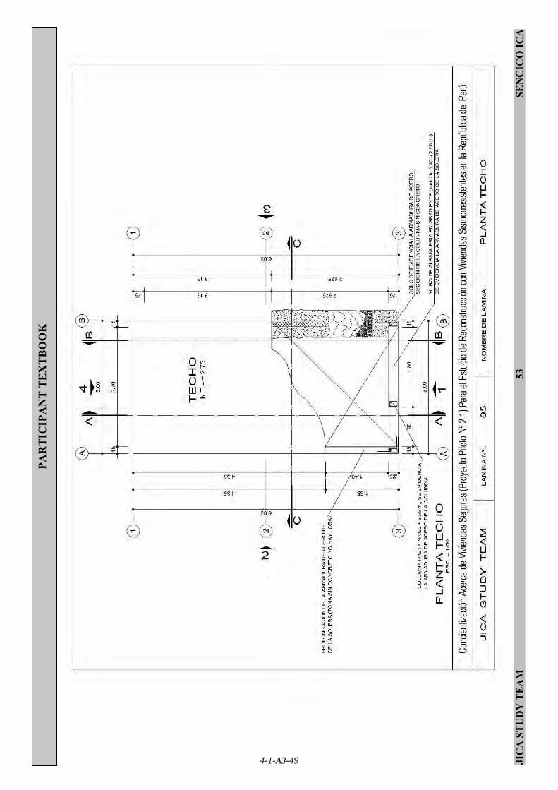
JIC
A S
TU
DY
TE
AM
53
SE
NC
ICO
ICA
PAR
TIC
IPA
NT
TE
XT
BO
OK
4-1-A3-49

JIC
A S
TU
DY
TE
AM
54
SE
NC
ICO
ICA
PAR
TIC
IPA
NT
TE
XT
BO
OK
4-1-A3-50

JIC
A S
TU
DY
TE
AM
55
SE
NC
ICO
ICA
PAR
TIC
IPA
NT
TE
XT
BO
OK
4-1-A3-51
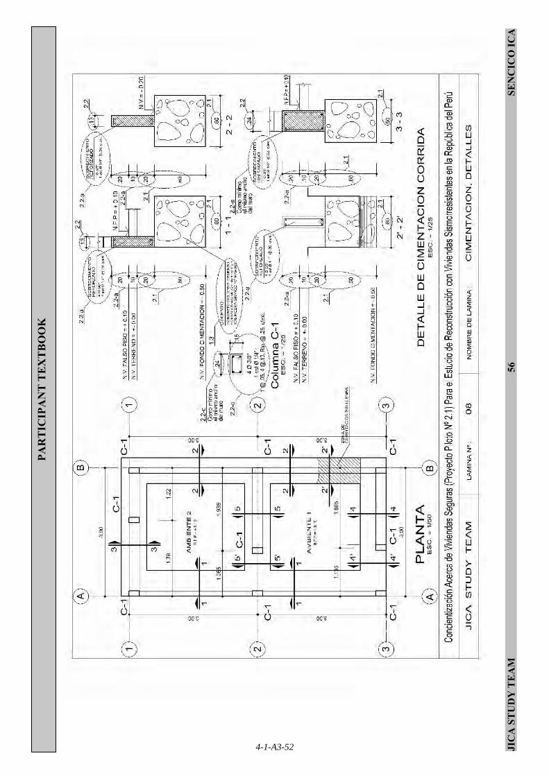
JIC
A S
TU
DY
TE
AM
56
SE
NC
ICO
ICA
PAR
TIC
IPA
NT
TE
XT
BO
OK
4-1-A3-52

JIC
A S
TU
DY
TE
AM
57
SE
NC
ICO
ICA
PAR
TIC
IPA
NT
TE
XT
BO
OK
4-1-A3-53

JIC
A S
TU
DY
TE
AM
58
SE
NC
ICO
ICA
PAR
TIC
IPA
NT
TE
XT
BO
OK
4-1-A3-54

JIC
A S
TU
DY
TE
AM
59
SE
NC
ICO
ICA
PAR
TIC
IPA
NT
TE
XT
BO
OK
4-1-A3-55

JIC
A S
TU
DY
TE
AM
60
SE
NC
ICO
ICA
PAR
TIC
IPA
NT
TE
XT
BO
OK
4-1-A3-56
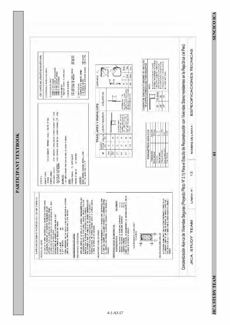
JIC
A S
TU
DY
TE
AM
61
SE
NC
ICO
ICA
PAR
TIC
IPA
NT
TE
XT
BO
OK
4-1-A3-57

JICA STUDY TEAM 62 SENCICO ICA
PARTICIPANT TEXTBOOK
REFERENCES:
Manual “Construcción y Mantenimiento de Viviendas de Albañilería” Universidad Católica del Perú 2006
Manuales didácticos “Encofrado y fierreria y albañilería”
SENCICO 2000
4-1-A3-58

Appendix 4
List of Trainees

Car
pio G
arcia
Car
men
38
FM
Jr. Ica
824
Puebl
o N
uevo
, C
hin
cha-
Ica
Car
riza
les
Roja
sH
ein
e22
MS
Av.
San
ta R
osa
403
Puebl
o N
uevo
, C
hin
cha-
Ica
Ccochac
hi C
anchar
iD
anie
l30
MM
Jr. L
os
Mar
tire
s 8
41, San
Isi
dro
Puebl
o N
uevo
, C
hin
cha-
Ica
Chav
ez
Sam
bran
oM
airy
28
FM
Jr. L
os
Mar
tire
s 8
41, San
Isi
dro
Puebl
o N
uevo
, C
hin
cha-
Ica
Cord
ova
Nuñez
Jony
34
MS
Cal
le J
ose
Ola
ya 3
22 S
anta
Rosa
Puebl
o N
uevo, C
hin
cha-
Ica
Cru
ces
Hija
rFlo
rF
SJr. S
an M
artí
n 1
07
Puebl
o N
uevo
, C
hin
cha-
Ica
Delg
ado d
e B
arriento
sM
aría
42
FM
Jr. J
org
e C
hav
ez
599-A
San
isi
dro
Puebl
o N
uevo
, C
hin
cha-
Ica
Fern
ànde
z Lujà
nLili
a35
FM
Urb
. León d
e V
ivero
Mz.
I, Lote
11
Puebl
o N
uevo
, C
hin
cha-
Ica
Gar
cia
Dia
zLuis
54
MS
UP
IS L
as A
méricas
Unid
as M
z 6 L
ote
7P
uebl
o N
uevo
, C
hin
cha-
Ica
Gar
cia
Zeta
Wilm
er
30
MM
AA
.HH
. El Sal
vado
r M
z C
Lote
4P
uebl
o N
uevo
, C
hin
cha-
Ica
Mat
ta Y
iachi
Pab
lo43
MM
Puebl
o N
uevo
, C
hin
cha-
Ica
Par
iona
Sal
vatierr
aEuse
bia
45
FA
A.H
H. V
illa
Sol M
ateo P
um
acah
ua
Mz
G lote
18
Puebl
o N
uevo
, C
hin
cha-
Ica
Quis
pe C
uba
Glo
ria
45
FM
Oliv
ia R
azeto
Mz
A L
ote
10
Puebl
o N
uevo
, C
hin
cha-
Ica
Quis
pe S
ote
loEuse
bio
49
MM
AA
.HH
. M
iguel G
rau M
z. P
Lote
3P
uebl
o N
uevo
, C
hin
cha-
Ica
Roja
s Flo
rez
Jorg
e24
MM
Av.
Mar
iscal
Benav
ides
872
Puebl
o N
uevo
, C
hin
cha-
Ica
San
chez
Tre
lles
Mig
uel
24
MS
Puebl
o N
uevo
, C
hin
cha-
Ica
Torr
es
San
tiag
oYan
ina
31
FS
Cal
le M
icae
la B
astida
s 560 S
anta
Rosa
Puebl
o N
uevo
, C
hin
cha-
Ica
Vill
avic
encio
Riv
era
Nik
ola
i24
MJr. T
upa
c A
mar
u 1
072 S
an Isi
dro
Puebl
o N
uevo
, C
hin
cha-
Ica
Yere
n P
arre
ño
Alic
ia39
FS
Av.
13 d
e o
ctu
bre 5
92
Puebl
o N
uevo
, C
hin
cha-
Ica
Yupa
Bau
tist
aLucía
26
FM
Fe y
Ale
gría
Mz
A L
ote
21
Puebl
o N
uevo
, C
hin
cha-
Ica
App
endi
x 4 L
ist
of
Tra
inees
Note
1)
Sex:
F;F
em
ale, M
;Mal
eN
ote
2) M
arital
sta
tus:
M; M
arried,
S;S
ingl
e
Dis
tric
t, Pr
ovin
ce-D
epar
tmen
tM
arita
lSt
atus
Fam
ily n
ame
Firs
tN
ame
Age
Sex
Add
ress
4-1-A4-1

Appendix 5
Daily Training Report

Appendix 5
Daily Training Report
Observations No. Date Main Topics
Less
on
Num
ber
Activities
N°
of
Par
ticip
ants
01 Knowing the land and reading the drawings Cartel installation :100% Land clearing: 100% Land border tracing: 100% (Percentage shows the progress of work)
1 Sept. 15
Start of training for cut model house building
Opening ceremony is going to be held tomorrow (Tuesday, September 16)
12
2 Sept. 16
Land tracing and soil quality test for foundation
01 Knowing the land and reading the drawings
- Excavation up to 1 m depth: 100% - Soil quality test:100% - Land tracing (Stakes and security
border installation): 60 %.
12
01 Knowing the land and reading the drawings - Soil quality test. Results obtained after
24 hours: 100% 02 Clearing, leveling and tracing the land
- Leveling: 100% - Land tracing (install trig beacons,
graphic method to find a 90° angle, and foundation tracing: 100%
3 Sept. 17
Land tracing
Cement is used for installing trig beacons properly, but some materials were not yet delivered at this time. The Instructor was asked to provide sufficient construction materials by JICA Study Team.
16
Sept. 18
Foundation tracing
02 Clearing, leveling and tracing the land -Theoretical lessons related to tracing of
land:100%
4
03 Excavating the ditch -Practice on foundation tracing (install trig beacons, graphic method to obtain
19
4-1-A5-1

90° angle and foundation tracing): 100%
Instructor said that participants are still lacking security shoes.
5 Sept. 19
Foundation excavation
03 Excavating the ditch -Theoretical lessons related to minimum
requirement:100% -Excavation of ditch of 80 cm. depth and
60 cm. width: 100%
19
04 Making the frameworks for columns. -Written test about activities 1, ,2 and 3:
100%
-Theoretical lesson about habilitation and installation of hoops for columns (Minimum Requirements): 100%
-Practice on hoops habilitation for
columns:100%
6 Sept. 22
Making the hoops and stirrups for beams and columns
Instructor asked about the possibility of pouring a 10 cm thick poor concrete before the foundation for soil leveling. JICA Study Team agreed with this in as much as training progress is not affected.
19
04 Making the frameworks for columns.
-Theoretical lesson about habilitation and installation of hoops for columns (Minimum Requirements): 100%
-Practice on hoops habilitation for
columns: 100%
7 Sept. 23
Making the hoops and stirrups for beams and columns
Engr. CAJACHAGUA (SENCICO ICA Manager) informed JICA Study Team that SENCICO will prepare a temporary space for theoretical lessons next to the “cut model house” (include seats and a roof).
19
04 Making the frameworks for columns.
-Theoretical lesson about preparation and installation of hoops for columns (Minimum Requirements): 100%
-Hoops preparation for columns: 50%
8 Sept. 24
Hoops for columns
Course Instructor was asked to hand over the digital file CVs of the Supervisor (educative and construction), Instructor and Assistant Instructor, JICA Study Team also asked about the Instructor Manual.
19
4-1-A5-2

04 Making the frameworks for columns. -Theoretical lesson about making and installing hoops and rebars for columns (Minimum Requirements). 100%
-Making hoops for columns. 100%
-Structuring rebars for columns. 50 %
9 Sept. 25
Making the hoops and rebars for columns
Today, SENCICO ICA prepared a place for theoretical lessons of the “cut model” (including 13 desks).
19
04 Making the frameworks for columns. -Theoretical lesson about reinforcement
steel bar processing and installing for columns (Minimum Requirements): 100%.
-Column steel bar processing: 100%.
10 Sept. 26
Making the hoops and steel bar habilitation for columns
SENCICO (Instructor) will deliver safety shoes next week. SENCICO ICA brought seven more desks.
20
04 Making the frameworks for columns. -Written test referred to activity 4: 100%
05 Building the foundation
-Theoretical lesson referred to foundation building (Minimum Requirements): 100%
-Making blocks for foundation: 100%
11 Sept. 29
Installation of concrete blocks on the foundation where columns are going to be placed. ADRA began Project 2.2
Due to the start of Project 2.2, SENCICO was told to improve and/or limit the spaces destined for construction materials storage. ADRA (Project 2.2) made the presentation on Saturday, Sept. 27 at Óvalo de la Juventud, from 8:00 p.m. to 10:00 p.m., and on Sunday, Sept. 28 at the side of the “CUT MODEL HOUSE” site from 5:00 p.m. to 7:15 p.m.
19
12 Sept. 30
Column framework installation
05 Building the foundation
-Theoretical lesson on foundation building (Minimum requirements): 100%
-Installing the column framework: 100%
20
13 Oct. 1 Concrete pouring in foundation
05 Building the foundation
-Theoretical lesson on foundation building (Minimum requirements): 100%
20
4-1-A5-3

-Pouring concrete mix in foundation: 100%
SENCICO delivered “INSTRUCTOR MANUAL”.
06 Making the frameworks for reinforced tie beam.
-Theoretical lesson about foundation building (Minimum requirements): 100%
-Tie beam steel preparation: 40%
14 Oct. 2 Making the tie beam steel framework
Press release on the pilot projects by JICA STUDY TEAM, shown after this table, was released to the following networks: EDUARDO ANCHANTE (CANAL 10), CRISTINA VILLAVERDE (CANAL 21), ROSARIO ANDIA (CANAL 2), FABIOLA SANCHEZ (CANAL 25) Y ERICK MORALES (CORREO).
20
Oct. 3 Habilitation of the steel framework of the RC tie beam
06 Making the frameworks for RC tie beam.
-Theoretical lesson about foundation building (Minimum requirements):100%
-RC tie beam steel preparation: 60%
-Reinforcement steel preparation and
installation in the RC tie beam-column connection zone: 70%
15
SENCICO gave security gear (shoes and trousers) to course participants.
20
16 Oct. 6 Habilitation of the steel framework of the RC tie beam
06 Making frameworks for RC tie beam.
-Theoretical lesson about foundation building (Minimum requirements):100%
-RC tie beam steel preparation: 75%
-Reinforcement steel preparation and
installation in the RC tie beam-column connection zone: 80%.
20
17 Oct. 7 SENCICO y ADRA did not have any activities due to a regional strike in Ica.
-
18 Oct. 8 SENCICO did not schedule any activities due to national holiday.
-
4-1-A5-4

19 Oct. 9 Habilitation of the steel framework of the RC tie beam
06 Making the frameworks for RC tie beam.
-Theoretical lesson about foundation building (Minimum requirements):100%
-RC tie beam steel preparation: 100%
-Reinforcement steel preparation and
installation in the RC tie beam-column connection zone: 100%.
18
20 Oct. 10
Tracing on the foundation for RC tie beam formwork
07 Making the formwork for RC tie beam
-Theoretical lesson related to RC tie beam formwork (Minimum requirements): 100%
-Tracing over the foundation: 100%
19
07 Prepare lumber yard and tie beam formwork
-Theoretical lesson about RC tie beam formwork (Minimum Requirements): 100%
-RC tie beam formwork: 50%
21 Oct. 13
RC tie beam formwork
Participants said that SENCICO has not yet given them their established allowance. SENCICO explained to the participants that although JICA has deposited the required money, Economy Ministry has yet to approve SENCICO budget for the allowance payment.
20
22 Oct. 14
RC tie beam formwork
07 Making the formwork for RC tie beam
-Theoretical lesson about RC tie beam formwork (Minimum Requirements): 100%
-RC tie beam formwork: 100%
19
23 Oct. 15
RC tie beam concrete pouring
08 Tie beam building
-Theoretical lesson about RC tie beam (Minimum Requirements): 100%
-Concrete preparation and pouring (1
part cement – 2 parts sand – 4 ½” parts crushed stone - 1 part water) in tie beam: 100%
19
4-1-A5-5

08 Tie beam building
-Taking out RC tie beam formwork
09 Laying the first row of bricks
-Theoretical lesson about laying first row of bricks (minimum requirements): 100%
-Laying first row of bricks to build a wall: 50%.
24 Oct. 16
Taking out RC tie beam formwork
A questionnaire and a partial test about knowledge comprehension given to participants to answer (total duration: 30 min.) by JICA Study Team.
20
Oct. 17
Building the walls
09 Laying the first row of bricks
-Laying first row of bricks: 100%
25
10 Building the wall
-Theoretical lesson about wall building (Minimum Requirements): 100%
- Wall building practice: 50%.
19
26 Oct. 20
Building the walls
10 Building the walls
-Theoretical lesson about construction of wall (Minimum Requirements):100%
-Wall building practice: 80%
18
27 Oct. 21
Building the walls
10 Building the walls
-Wall Building practice:100%
18
28 Oct. 22
Building the walls
10 Building the walls -Theoretical lesson about wall building:
100% -Building of walls: 10%
18
29 Oct. 23
Building the walls
10 Building the walls
-Theoretical lesson about wall construction (Minimum Requirements): 100%
-Building of walls: 30%
19
4-1-A5-6

30 Oct. 24
Building the walls
10 Building the wall
-Theoretical lesson on wall building (Minimum Requirements): 100%
-Building of walls: 60%
19
31 Oct. 25
10 Building the wall
-Theoretical lesson on wall building (Minimum Requirements): 100%
-Building of walls: 75%
19
10 Building the wall -Theoretical lesson on wall building (Minimum Requirements).100% -Building of walls: 90%
32 Oct. 28
Building the walls
11 column formwork and pouring concrete mix
-Theoretical lesson on column formwork (Minimum Requirements): 100%
- Column formwork: 15%
19
33 Oct. 29
Building the walls
10 Building the wall
-Theoretical lesson on wall building (Minimum Requirements).100%
-Building of walls: 95%
19
10 Building the wall -Building of walls: 100%
34 Oct. 30
Building the walls
11 Column formwork and concrete pouring
-Theoretical lesson on column formwork (Minimum Requirements).100%
- Column formwork: 20%
19
35 Oct. 31
Column formwork
11 Column formwork and concrete pouring
-Theoretical lesson on column formwork (Minimum Requirements): 100%
-Land clearing: 100% - Column formwork. 80%
19
4-1-A5-7

36 Nov. 3 Column formwork and mix pouring
11 Column formwork and concrete pouring
-Theoretical lesson on column formwork and pouring concrete mix (Minimum Requirements): 100% - Column formwork: 100% -Mix pouring. 100%
19
37 Nov. 4 Column formwork and mix pouring
11 Column formwork and concrete pouring
-Remove column formwork: 100% -Moist curing columns: 30%
19
38 Nov. 5 Concrete pouring in floor
11 Column formwork and pouring concrete mix
-Moist curing columns: 60% -Concrete pouring in floor (10 cm): 100%
19
11 Column formwork and concrete pouring -Moist curing columns: 80%
12 Wood preparation and ring beam formwork -None
39 Nov. 6 Ring beam framework installation
13 Ring beam framework making
-Theoretical lesson on ring beam framework making (Minimum requirements): 100%
-Stirrups habilitation for ring beam: 30%
19
11 Column formwork and concrete pouring -Moist curing columns: 100%
40 Nov. 7 Slab formwork installation
12 Wood preparation and ring beam formwork
-Theoretical lesson on wood preparation and ring beam formwork (Minimum requirements): 100% -Habilitating the ring beam formwork:
18
4-1-A5-8

40%
13 Ring beam framework making
-Theoretical lesson on ring beam framework making (Minimum requirements): 100%
-Installing the ring beam framework: 30%
14 Slab formwork
-Theoretical lesson on slab formwork
(Minimum requirements). 100% -Slab formwork: 40%
12 Wood preparation and ring beam
formwork
-Theoretical lesson on wood preparation and ring beam formwork (Minimum requirements): 100%
-Habilitating the ring beam formwork:
50%
13 Ring beam framework making
-Theoretical lesson on ring beam framework making (Minimum requirements): 100%
-Installing the ring beam framework: 60%
41 Nov. 10
Ring beam framework installation
14 Slab formwork
-Theoretical lesson on slab formwork (Minimum requirements). 100%
-Slab formwork: 60%
19
12 Wood preparation and ring beam formwork -Habilitating the ring beam formwork:
100%
42 Nov. 11
Ring beam framework installation and slab formwork installation
13 Ring beam framework making -Installing the ring beam framework:
100%
20
4-1-A5-9
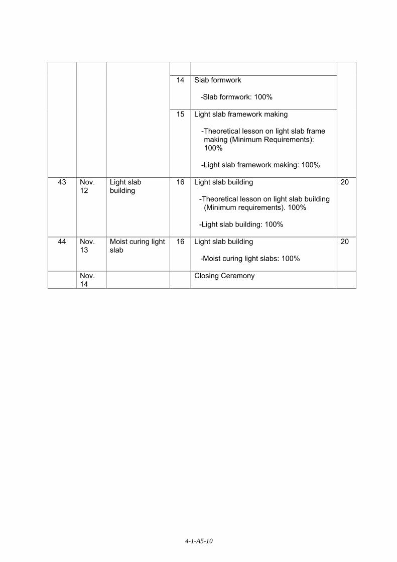
14 Slab formwork -Slab formwork: 100%
15 Light slab framework making
-Theoretical lesson on light slab frame making (Minimum Requirements): 100%
-Light slab framework making: 100%
43 Nov.
12 Light slab building
16 Light slab building
-Theoretical lesson on light slab building (Minimum requirements). 100%
-Light slab building: 100%
20
44
Nov. 13
Moist curing light slab
16 Light slab building -Moist curing light slabs: 100%
20
Nov. 14
Closing Ceremony
4-1-A5-10

25 September 2008
Press Release on JICA Housing Reconstruction Pilot Projects
Under the Peru-Japan cooperation, JICA Study Team of Housing Reconstruction of Japan International Cooperation Agency (JICA), in cooperation with MVCS of the Government of Peru, has started implementing three Housing Reconstruction Pilot Projects in three municipalities of Ica region, namely La Tinguina, Pueblo Nuevo and Independencia. These Pilot Projects are designed to evaluate, in terms of effectiveness and possibility of implementation, the Full Phase of the housing reconstruction projects. These projects aim to assist the people to facilitate the reconstruction of the houses they lost as a result of the strong earthquake of August 15, 2007.
Pilot Project No.1 Project to accelerate dissemination of a Safer House against Earthquake
Activities: (1) Prototype drawings of seismic-resistant house
(2) Manual of construction method of seismic-resistant house
(3) Manual of building permits of safer houses
Pilot Project No.2 Project to accelerate Dissemination of Construction Technologies and Knowledge of a Safer House against Earthquake Activities: (1) Introduction of minimum requirements of safer house.
(2) Illustration of construction process
(3) A VCR for seismic behavior in shaking table
(4) Brief drama to promote safe house
(5) One day training for affected people
(6) Information dissemination on reinforced adobe model house
(7) Model house construction at site
Pilot Project No.3 Project to facilitate access to Housing Reconstruction Subsidy (BONO 6000 and Techo Propio) Activities: (1) Dissemination of financial mechanisms of the government funded program
(2) One-stop Kiosk for housing reconstruction
4-1-A5-11

Timing and Venues of Projects: PP1: Second week of Oct 2008 (La Tinguina, Pueblo Nuevo, Independencia)
PP2: Sept. 27 to Nov. 9 (Centro de Capacitacion, Chincha)
PP3: From Sept. 19 to Oct. 6, Pueblo Nuevo
For further information, pls. contact:
Denise Kiyomoto 01 997 721 001 (in Lima)
Gustavo Quijada 01 996 606 205 (in Ica Region)
4-1-A5-12


