EPA 816-R-04-003 Appendix A Hydraulic Fracturing White Paper Appendix A Department of Energy - Hydraulic Fracturing White Paper 1.0 Introduction The first hydraulic fracturing treatment was pumped in 1947 on a gas well operated by Pan American Petroleum Corporation in the Hugoton field. 1 The Kelpper Well No. 1, located in Grant County, Kansas was a low productivity well, even though it had been acidized. The well was chosen for the first hydraulic fracture stimulation treatment so that hydraulic fracturing could be compared directly to acidizing. Since that first treatment in 1947, hydraulic fracturing has become a standard treatment for stimulating the productivity of oil and gas wells. Hydraulic fracturing is the process of pumping a fluid into a wellbore at an injection rate that is too high for the formation to accept in a radial flow pattern. As the resistance to flow in the formation increases, the pressure in the wellbore increases to a value that exceeds the breakdown pressure of the formation that is open to the wellbore. Once the formation “breaks-down”, a crack or fracture is formed, and the injected fluid begins moving down the fracture. In most formations, a single, vertical fracture is created that propagates in two directions from the wellbore. These fracture “wings” are 180 o apart, and are normally assumed to be identical in shape and size at any point in time. In naturally fractured or cleated formations, such as gas shales or coal seams, it is possible that multiple fractures can be created and propagated during a hydraulic fracture treatment. Fluid that does not contain any propping agent, often called “pad”, is injected to create a fracture that grows up, out and down, and creates a fracture that is wide enough to accept a propping agent. The purpose of the propping agent is to “prop open” the fracture once the pumping operation ceases, the pressure in the fracture decreases, and the fracture closes. In deep reservoirs, we use man-made ceramic beads to prop open the fracture. In shallow reservoirs, sand is normally used as the propping agent. The sand used as a propping agent in shallow reservoirs, such as coal seams, is mined from certain quarries in the United States. The silica sand is a natural product and will not lead to any environmental concerns that would affect the United States Drinking Water (USDW). The purposes of this paper are (1) to discuss the processes an engineer uses to design and pump a hydraulic fracture treatment, and (2) to provide an overview of the theories, design methods and materials used in a hydraulic fracture treatment. Currently, a discussion is taking place on the effects of hydraulic fracturing in coal seams on the USDW. Gas production from coal seams is increasing in importance in the United States. In 2000, over 6% of the natural gas production in the US was produced from coal seams, and that percentage will increase in the future. Because of the ever-increasing importance of natural gas production from coal seams, coal seam examples have been included in this technical paper. Objectives of Hydraulic Fracturing In general, hydraulic fracture treatments are used to increase the productivity index of a producing well, or the injectivity index of an injection well. The productivity index defines the volumes of oil or gas that can be produced at a given pressure differential between the reservoir and the well bore. The injectivity index refers to how much fluid can be injected into an injection well at a given pressure differential. There are many different applications for hydraulic fracturing, such as: Evaluation of Impacts to Underground Sources June 2004 of Drinking Water by Hydraulic Fracturing of Coalbed Methane Reservoirs App. A-1
Transcript
EPA 816-R-04-003 Appendix A Hydraulic Fracturing White Paper
Appendix A Department of Energy - Hydraulic Fracturing White Paper
1.0 Introduction
The first hydraulic fracturing treatment was pumped in 1947 on a gas well operated by Pan American Petroleum Corporation in the Hugoton field.1 The Kelpper Well No. 1, located in Grant County, Kansas was a low productivity well, even though it had been acidized. The well was chosen for the first hydraulic fracture stimulation treatment so that hydraulic fracturing could be compared directly to acidizing. Since that first treatment in 1947, hydraulic fracturing has become a standard treatment for stimulating the productivity of oil and gas wells.
Hydraulic fracturing is the process of pumping a fluid into a wellbore at an injection rate that is too high for the formation to accept in a radial flow pattern. As the resistance to flow in the formation increases, the pressure in the wellbore increases to a value that exceeds the breakdown pressure of the formation that is open to the wellbore. Once the formation “breaks-down”, a crack or fracture is formed, and the injected fluid begins moving down the fracture. In most formations, a single, vertical fracture is created that propagates in two directions from the wellbore. These fracture “wings” are 180o apart, and are normally assumed to be identical in shape and size at any point in time. In naturally fractured or cleated formations, such as gas shales or coal seams, it is possible that multiple fractures can be created and propagated during a hydraulic fracture treatment.
Fluid that does not contain any propping agent, often called “pad”, is injected to create a fracture that grows up, out and down, and creates a fracture that is wide enough to accept a propping agent. The purpose of the propping agent is to “prop open” the fracture once the pumping
operation ceases, the pressure in the fracture decreases, and the fracture closes. In deep reservoirs, we use man-made ceramic beads to prop open the fracture. In shallow reservoirs, sand is normally used as the propping agent. The sand used as a propping agent in shallow reservoirs, such as coal seams, is mined from certain quarries in the United States. The silica sand is a natural product and will not lead to any environmental concerns that would affect the United States Drinking Water (USDW).
The purposes of this paper are (1) to discuss the processes an engineer uses to design and pump a hydraulic fracture treatment, and (2) to provide an overview of the theories, design methods and materials used in a hydraulic fracture treatment. Currently, a discussion is taking place on the effects of hydraulic fracturing in coal seams on the USDW. Gas production from coal seams is increasing in importance in the United States. In 2000, over 6% of the natural gas production in the US was produced from coal seams, and that percentage will increase in the future. Because of the ever-increasing importance of natural gas production from coal seams, coal seam examples have been included in this technical paper.
Objectives of Hydraulic Fracturing
In general, hydraulic fracture treatments are used to increase the productivity index of a producing well, or the injectivity index of an injection well. The productivity index defines the volumes of oil or gas that can be produced at a given pressure differential between the reservoir and the well bore. The injectivity index refers to how much fluid can be injected into an injection well at a given pressure differential.
There are many different applications for hydraulic fracturing, such as:
Evaluation of Impacts to Underground Sources June 2004 of Drinking Water by Hydraulic Fracturing of Coalbed Methane Reservoirs App. A-1
EPA 816-R-04-003 Appendix A Hydraulic Fracturing White Paper
• Increase the flow rate of oil and/or gas from low permeability reservoirs,
• Increase the flow rate of oil and/or gas from wells that have been damaged,
• Connect the natural fractures and/or cleats in a formation to the wellbore,
• Decrease the pressure drop around the well to minimize sand production,
• Decrease the pressure drop around the well to minimize problems with asphaltine and/or paraffin deposition,
• Increase the area of drainage or the amount of formation in contact with the wellbore, and
• Connect the full vertical extent of a reservoir to a slanted or horizontal well.
Obviously, there could be other uses of hydraulic fracturing, but the majority of the treatments are pumped for these seven reasons.
A low permeability reservoir is one that has a high resistance to fluid flow. In many formations, chemical and/or physical processes alter a reservoir rock over geologic time. Sometimes, these diagenetic processes restrict the openings in the rock and reduce the ability of fluids to flow through the rock. Low permeability rocks are normally excellent candidates for stimulation by hydraulic fracturing.
Regardless of the permeability, a reservoir rock can be damaged when a well is drilled through the reservoir and when casing is set and cemented in place. Damage occurs because drilling and/or completion fluids leak into the reservoir and plug up the pores and pore throats. When the pores are plugged, the permeability is reduced, and the fluid flow in this damaged portion of the reservoir may be substantially reduced. Damage can be severe in naturally fractured reservoirs, like coal seams. To stimulate damaged reservoirs, a short, conductive hydraulic fracture is often the desired solution. As such, hydraulic fracturing works very well in many damaged, coal seam reservoirs.
In many cases, especially for low permeability formations, damaged reservoirs and horizontal wells in a layered reservoir, the well would be “uneconomic” unless a successful hydraulic fracture treatment is designed and pumped. Thus, the engineer in charge of the economic success of such a well, must (1) design the optimal fracture treatment, and then (2) go to the field to be certain the optimal treatment is pumped successfully.
Candidate Selection
The success or failure of a hydraulic fracture treatment often depends on the quality of the candidate well selected for the treatment. Choosing an excellent candidate for stimulation often ensures success, while choosing a poor candidate will normally result in economic failure. To select the best candidate for stimulation, the design engineer must consider many variables. The most critical parameters for hydraulic fracturing are formation permeability, the in-situ stress distribution, reservoir fluid viscosity, skin factor, reservoir pressure, reservoir depth and the condition of the wellbore. The skin factor refers to whether the reservoir is already stimulated or, perhaps is damaged. If the skin factor is positive, the reservoir is damaged and could possibly be an excellent candidate for stimulation.
The best candidate wells for hydraulic fracturing treatments will have a substantial volume of oil and gas in place, and will have a need to increase the productivity index. Such reservoirs will have (1) a thick pay zone, (2) medium to high pressure, (3) in-situ stress barriers to minimize vertical height growth, and (4) either be a low permeability zone or a zone that has been damaged (high skin factor). For coalbed methane reservoirs, the ideal candidate, in addition to the 4 factors listed above, will be a thick coal seam containing both (1) a large volume of sorbed gas and (2) abundant coal cleats to provide permeability.
Evaluation of Impacts to Underground Sources June 2004 of Drinking Water by Hydraulic Fracturing of Coalbed Methane Reservoirs App. A-2
EPA 816-R-04-003 Appendix A Hydraulic Fracturing White Paper
Reservoirs that are not good candidates for hydraulic fracturing are those with little oil or gas in place due to thin reservoirs, low reservoir pressure, or small aerial extent. Reservoirs with extremely low permeability may not produce enough hydrocarbons to pay all the drilling and completion costs even if successfully stimulated; thus, such reservoirs would not be good candidates for stimulation. In coal seam reservoirs, the number, thickness and location of the coal seams must be considered when deciding if the coals can be completed and stimulated economically. If the coal seams are too thin or too scattered up and down the hole, the coals may not be ideal candidates for stimulation by hydraulic fracturing.
Developing Data Sets
For most petroleum engineering problems, developing a complete and accurate data set is often the most time consuming part of solving the problem. For hydraulic fracture treatment design, the data required to run both the fracture design model and the reservoir simulation model can be divided into two groups. One group lists the data that can be “controlled” by the engineer. The second group reflects data that must be measured or estimated, but cannot be controlled.
The primary data that can be controlled by the engineer are the well completion details, treatment volume, pad volume, injection rate, fracture fluid viscosity, fracture fluid density, fluid loss additives, propping agent type, and propping agent volume. The data that must be measured or estimated by the design engineer are formation depth, formation permeability, in-situ stresses in the pay zone, in-situ stresses in the surrounding layers, formation modulus, reservoir pressure, formation porosity, formation compressibility, and the thickness of the reservoir. There are actually three (3) thickness that are important to the design engineer: the gross thickness of the reservoir; the net thickness of the oil or gas producing interval; and the
permeable thickness that will accept fluid loss during the hydraulic fracture treatment.
The most critical data for the design of a fracture treatment are, roughly in order of importance, (1) the in-situ stress profile, (2) formation permeability, (3) fluid loss characteristics, (4) total fluid volume pumped, (5) propping agent type and amount, (6) pad volume, (7) fracture fluid viscosity, (8) injection rate, and (9) formation modulus. Since most engineers have more work to do than time to do the work, the design engineer should focus most of his/her time on the most important parameters. In hydraulic fracture treatment design, by far, the two most important parameters are the in-situ stress profile and the permeability profile of the zone to be stimulated and the layers of rock above and below the target zone.
In new fields or reservoirs, most operating companies are normally willing to spend money to run logs, cut cores and run well tests to determine important factors such as the in-situ stress and the permeability of the major reservoir layers. By using such data, along with fracture treatment records and production records, accurate data sets for a given reservoir in a given field can normally be compiled. These data sets can be used on subsequent wells to optimize the fracture treatment designs. It is normally not practical to cut cores and run well tests on every well. Thus, the data obtained from cores and well tests must be correlated to log parameters so the logs on subsequent wells can be used to compile accurate data sets.
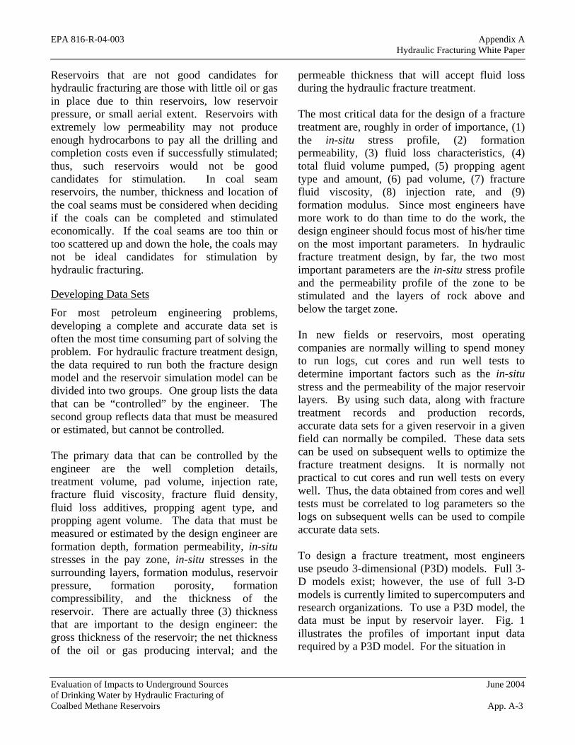
To design a fracture treatment, most engineers use pseudo 3-dimensional (P3D) models. Full 3D models exist; however, the use of full 3-D models is currently limited to supercomputers and research organizations. To use a P3D model, the data must be input by reservoir layer. Fig. 1 illustrates the profiles of important input data required by a P3D model. For the situation in
Evaluation of Impacts to Underground Sources June 2004 of Drinking Water by Hydraulic Fracturing of Coalbed Methane Reservoirs App. A-3
SandSand
5050'
EPA 816-R-04-003 Appendix A Hydraulic Fracturing White Paper
Fig. 1, the fracture treatment would be initiated in Table 1 – Sources of Data the sandstone reservoir. The fracture would typically grow up and down until a barrier is reached to prevent vertical fracture growth. In many cases, thick marine shale will be a barrier to vertical fracture growth. In some cases, coal seams will prevent fractures from growing vertically. Many coal seams are highly cleated, and when the fracture fluid enters the coal seam, it remains contained within the coal seam. In thick, highly cleated coal seams, the growth of the hydraulic fracture will normally be limited to the coal seam.
The data used to design a fracture treatment can be obtained from a number of sources, such as drilling records, completion records, well files, open hole geophysical logs, cores and core analyses, well tests, production data, geologic records, and other public records, such as publications. In addition, service companies provide data on their fluids, additives and propping agents. Table 1 illustrates typical data needed to design a fracture treatment and possible sources for the data.
Fracture Treatment Optimization
The goal of every design engineer should be to design the optimum fracture treatment for each and every well. In 1978, Holditch et al.2 wrote a paper concerning the optimization of both the
Data Units Sources Formation Permeability md Cores, Well Tests,
Correlations, Production Data
Formation Porosity % Cores, Logs Reservoir Pressure psi Well Tests, Well Files,
Regional Data Formation Modulus psi Cores, Logs,
Correlations Formation Compressibility
psi Cores, Logs, Correlations
Poisson’s Ratio Cores, Logs, Correlations
Formation Depth ft Logs, Drilling Records In-situ Stress psi Well Tests, Logs,
Correlations Formation Temperature °F Logs, Well Tests,
Correlations Fracture Toughness psi - in Cores, Correlations
Water Saturation % Logs, Cores Net Pay Thickness Ft Logs, Cores Gross Pay Thickness Ft Logs, Cores, Drilling
Records Formation Lithology Cores, Drilling
Records, Logs, Geologic Records
Wellbore Completion Well Files, Completion Prognosis
Fracture Fluids Service Company Information
Fracture Proppants Service Company Information
propped fracture length and the drainage area (well spacing) for low permeability gas reservoirs. Fig. 2 illustrates the methodology used to optimize the size of a fracture treatment 3,4. Fig. 2 clearly shows the following:
• As the propped length of a fracture increases, the cumulative production will increase, and the revenue from hydrocarbon sales will increase,
• As the fracture length increases, the incremental benefit ($ of revenue per foot of additional propped fracture length) decreases,
• As the treatment volume increases, the propped fracture length increases,
• As the fracture length increases, the incremental cost of each foot of fracture ($ of cost per foot of additional propped fracture length) increases, and
Evaluation of Impacts to Underground Sources June 2004 of Drinking Water by Hydraulic Fracturing of Coalbed Methane Reservoirs App. A-4
EPA 816-R-04-003 Appendix A Hydraulic Fracturing White Paper
• When the incremental cost of the treatment is compared to the incremental benefit of increasing the treatment volume, an optimum propped fracture length can be found for every situation.
Additional economic calculations can be made to determine the optimum fracture treatment design. However, in all cases, the design engineer must consider the effect of the fracture upon flow rates and recovery, the cost of the treatment, and the investment guidelines of the operator of the well.
Field Considerations
After the optimum fracture treatment has been designed, it must be pumped into the well successfully. A successful field operations requires planning, coordination and cooperation of all parties. Treatment supervision and the use of quality control measures will improve the successful application of hydraulic fracturing. Safety is always the primary concern in the field. Safety begins with a thorough understanding by all parties on their duties in the field. A safety meeting is always held to review the treatment procedure, establish a chain of command, be sure
Lf = 1,500
Lf = 500
Lf = 1,000ReservoirReservoirSimulatorSimulator
Cum. Prod.
Time
HydrafracHydrafracSimulatorSimulator
everyone knows his/her job responsibilities for the day, and to establish a plan for emergencies. The safety meeting should also be used to discuss the well completion details and the maximum allowing injection rate and pressures, as well as the maximum pressures to be held as backup to an annulus. All casing, tubing, wellheads, valves, and weak links, such as liner tops, should be thoroughly tested prior to rigging up the fracturing equipment. Mechanical failures during a treatment can be costly and dangerous. All mechanical problems should be repaired prior to pumping the fracture treatment.
Prior to pumping the treatment, the engineer-in-charge should conduct a detailed inventory of all the equipment and materials on location. The inventory should be compared to the design and the prognosis. After the treatment has concluded, the engineer should conduct another inventory of all the materials left on location. In most cases, the difference in the two inventories can be used to verify what was mixed and pumped into the wellbore and the hydrocarbon bearing formation.
$ Revenue
Fracture Length
$ Revenue Less
$ Cost
Fracture Length
$Treatment CostVolume
Fracture Length Fracture Length
Fig. 2 – Fracture treatment optimization process.
Evaluation of Impacts to Underground Sources June 2004 of Drinking Water by Hydraulic Fracturing of Coalbed Methane Reservoirs App. A-5
EPA 816-R-04-003 Appendix A Hydraulic Fracturing White Paper
In addition to an inventory, samples of the base fracturing fluid (usually water) should be taken and analyzed. Typically, a water analysis is done on the base fluid to determine the minerals present and the type of bacteria in the water. The data from the water analysis can be used to select the additives required to mix the viscous fracture fluid required to create a wide fracture and to transport the propping agent into the fracture. Table 2 shows the typical compositions for mix waters used in different fracturing situations. In addition to testing the water, samples of the additives used during a treatment and the fracture fluid after all additives have been added should be taken during the job and saved for future analyses, if required.
Table 2 – Fracturing Fluids and Conditions for Their Use
Base FluidBase Fluid Fluid TypeFluid TypeMainMainMain
CompositionCompositionComposition Used ForUsed For
Gelled ter, Short Fractures,Short Fractures,Low TemperaturesLow Temperatures
CrosslinkedCrosslinkedCrosslinked Crosslinker +Crosslinker +Crosslinker + Long Fractures,Long Fractures,FFFllluidsuidsuids GUAR, HPG,GUAR, HPG,GUAR, HPG, High TemperaturesHigh Temperatures
CMHPG, CMHECCMHPG, CMHECCMHPG, CMHEC
Water BasedWater BasedWater BasedFoamFoamFoam
Water andWater andWater andFoamer + N2 or CO2Foamer + N2 or CO2Foamer + N2 or CO2
Low Pressure FormatLow Pressure Formatiionsons
Foam BasedFoam Based AcAciid Based Foamd Based Foam AcAcAciiid and Foamerd and Foamerd and Foamer Low Pressures, WaterLow Pressures, Water+ N2+ N2+ N2 Sensitive FormatSensitive Formatiionsons
Water SensWater Sensiittiive Formations,ve Formations,Long FracturesLong Fractures
Water ExternalWater ExternalWater ExternalEmuEmuEmulllsionssionssions
Water + Oil +Water + Oil +Water + Oil +EmulsEmulsEmulsiiifffiiiererer Good For Fluid Loss ControGood For Fluid Loss Controll
Formation temperature is one of the main factors concerning the type of additives required to mix the optimum fracturing fluid. In deep, hot reservoirs (>250oF), more additives are required than in shallow, low temperature reservoirs. Since most coal seams are very shallow, fewer additives are normally required to mix the optimum fracture fluid.
2.0 Fracture Mechanics
Fracture mechanics has been part of mining engineering and mechanical engineering for hundreds of years. No one is more interested in underground rock fractures than a miner working in an underground mine. In petroleum engineering, we have only used fracture mechanics theories in our work for about 50 years. Much of what we use in hydraulic fracturing theory and design has been developed by other engineering disciplines many years ago. However, certain aspects, such as poroelastic theory, are unique to porous, permeable underground formations. The most important parameters are in-situ stress, Poisson’s ration, and Young’s modulus.
In-situ Stresses
Underground formations are confined and under stress. Fig. 3 illustrates the local stress state at depth for an element of formation. The stresses can be divided into 3 principal stresses. In Fig. 3, σ1 is the vertical stress, σ2 is the maximum horizontal stress, while σ3 is the minimum horizontal stress, where σ1>σ2>σ3. This is a typical configuration for coalbed methane reservoirs. However, depending on geologic conditions, the vertical stress could also be the intermediate (σ2) or minimum stress (σ3). These stresses are normally compressive and vary in magnitude throughout the reservoir, particularly in the vertical direction (from layer to layer). The magnitude and direction of the principal stresses are important because they control the pressure required to create and propagate a fracture, the shape and vertical extent of the fracture, the direction of the fracture, and the stresses trying to crush and/or embed the propping agent during production.
A hydraulic fracture will propagate perpendicular to the minimum principal stress (σ3). If the minimum horizontal stress is σ3, the fracture will
Evaluation of Impacts to Underground Sources June 2004 of Drinking Water by Hydraulic Fracturing of Coalbed Methane Reservoirs App. A-6
EPA 816-R-04-003 Appendix A Hydraulic Fracturing White Paper
be vertical and, we can compute the minimum horizontal stress profile with depth using Eq. 1.
σ1
3σ
σ1σ1
3σ3σ
σ1σ1
3σ3σ
σ1σ1
3σ3σσσσσσσσ2222222
σ1 >σ1 >σ1σ1 >σ1 >σ1σ1 >σ1σ1 >σ1σ1 >> σσσσσσσσσσσ3 >3 >33>3 >33>33>33>>σσσσσσσσσσσσσ2222222222222Fig. 3 – Local in-situ stress at depth.
νσmin ≅
1 ν− (σob σα− ) σα+ p σ+ ext Eq. 1p
Where:
σmin = the minimum horizontal stress (in-situ stress)
ν = Poissons’ ratio σob = overburden stress α = Biot’s constant σp = reservoir fluid pressure or pore
pressure σext = tectonic stress
Poisson’s ratio can be estimated from acoustic log data or from correlations based upon lithology. For coal seams, the value of Poisson’s ratio will range from 0.2 – 0.4. The overburden stress can be computed using density log data. Normally, the value for overburden pressure is about 1.1 psi per foot of depth. The reservoir pressure must be measured or estimated. Biot’s constant must be less than or equal to 1.0 and typically ranges from 0.5 to 1.0. The first two (2) terms on the right hand side of Eq.1 represent the horizontal stress resulting from the vertical stress and the poroelastic behavior of the formation. The tectonic stress term is important in many areas
where plate tectonics or other forces increase the horizontal stresses.
Poroelastic theory can be used to determine the minimum horizontal stress in tectonically relaxed areas.8,9 Poroelastic theory combines the equations of linear elastic stress-strain theory for solids with a term that includes the effects of fluid pressure in the pore space of the reservoir rocks. The fluid pressure acts equally in all directions as a stress on the formation material. The “effective stress” on the rock grains is computed using linear elastic stress-strain theory. Combining the two sources of stress results in the total stress on the formation, which is the stress that must be exceeded to initiate fracturing.
In many areas, however, the effects of tectonic activity must be included in the analyses of the total stresses. To measure the tectonic stresses, injection tests are conducted to measure the minimum horizontal stress. The measured stress is then compared to the stress calculated by the poroelastic equation to determine the value of the tectonic contribution.
Basic Rock Mechanics
In addition to the in-situ or minimum horizontal stress, other rock mechanical properties are important when designing a hydraulic fracture. Poisson’s ratio is defined as “the ratio of lateral expansion to longitudinal contraction for a rock under a uniaxial stress condition”.10 The value of Poisson’s ratio is used in Eq. 1 to convert the effective vertical stress component into an effective horizontal stress component. The effective stress is defined as the total stress minus the pore pressure.
The theory used to compute fracture dimensions is based upon linear elasticity. To apply this theory, the modulus of the formation is an important parameter. Young’s modulus is defined as “the ratio of stress to strain for uniaxial stress”.10 The modulus of a material is a measure
Evaluation of Impacts to Underground Sources June 2004 of Drinking Water by Hydraulic Fracturing of Coalbed Methane Reservoirs App. A-7
EPA 816-R-04-003 Appendix A Hydraulic Fracturing White Paper
of the stiffness of the material. If the modulus is large, the material is stiff. In hydraulic fracturing, a stiff rock will result in more narrow fractures. If the modulus is low, the fractures will be wider. The modulus of a rock will be a function of the lithology, porosity, fluid type, and other variables. Table 3 illustrates typical ranges for modulus as a function of lithology.
Table 3. Typical Ranges of Young’s Modulus for Various Lithologies
Lithology Young’s Modulus
Soft Sandstone 2-5 x 10⁶ psi
Hard Sandstone 6-10 x 106 psi
Limestone 8-12 x 106 psi
Coal 0.1-1 x 10⁶ psi
Shale 1-10 x 106 psi
Because coal is highly cleated, the modulus of the coal seam in-situ may be very low. In very low modulus, highly cleated coal seams, it is likely that most fractures will be wide and short, that is, not penetrating far into the formation from the well bore.
Fracture Orientation
A hydraulic fracture will propagate perpendicular to the least principle stress (Fig. 3). In some shallow formations the least principal stress is the overburden stress; thus, the hydraulic fracture will be horizontal. Nielsen and Hansen published a paper where horizontal fractures in coal seam reservoirs were documented 11. In reservoirs deeper than 1000 ft or so, the least principal stress will likely be horizontal; thus, the hydraulic fracture will be vertical. The azimuth orientation of the vertical fracture will depend upon the azimuth of the minimum and maximum horizontal stresses. Lacy and Smith provided a detailed discussion of fracture azimuth in SPE Monograph 12.12
Injection Tests
The only reliable technique for measuring in-situ stress is by pumping into a reservoir, creating a fracture, and measuring the pressure at which the fracture closes 13. The well tests used to measure the minimum principal stress are as follows: in-situ stress tests; step-rate/flow back tests; mini-fracture tests; and step-down tests. For most fracture treatments, mini-fracture tests and step-down tests are pumped ahead of the main fracture treatment. As such, accurate data are normally available to calibrate and interpret the pressures measured during a fracture treatment. In-situ stress tests and step-rate/flow back tests are not run on every well. However, it is common to run such tests in new fields or new reservoirs to help develop the correlations required to optimize fracture treatments for subsequent wells.
An in-situ stress test (or micro-frac) can be either an injection-falloff test or an injection-flow back test. The in-situ stress test is conducted using small volumes of fluid (a few barrels), injected at low injection rates (gals/min), normally using straddle packers to minimize well bore storage effects, into a small number of perforations (1-2 ft). The objective is to pump a thin fluid (water or nitrogen) at a rate barely sufficient to create a small fracture. Once the fracture is open, then the pumps are shut down, and the pressure is recorded and analyzed to determine when the fracture closes. Thus, fracture closure pressure is synonymous with in-situ stress and with minimum horizontal stress. When the pressure in the fracture is greater than the fracture closure pressure, the fracture is open. When the pressure in the fracture decreases below the fracture closure pressure, the fracture is closed. Fig. 4 illustrates a typical wellbore configuration for conducting an in-situ stress test. Fig. 5 shows typical data that are measured. Multiple tests are conducted to ensure repeatability. The data from any one of the injection-falloff tests can be analyzed to determine when the fracture closes.
Evaluation of Impacts to Underground Sources June 2004 of Drinking Water by Hydraulic Fracturing of Coalbed Methane Reservoirs App. A-8
EPA 816-R-04-003 Appendix AHydraulic Fracturing White Paper
Evaluation of Impacts to Underground Sources June 2004of Drinking Water by Hydraulic Fracturing ofCoalbed Methane Reservoirs App. A-9
Fig. 6 illustrates how one such test can beanalyzed to determine in-situ stress.
Falloff
SRO gaugeSeating nipple
Packer Perforated joint
Bridge plugPerforated sub
InjectionElectric wireline
Tubing
PerforationsMRO gauge
MRO gauge
30 ft 30 ft
Fluid
Falloff
SRO gaugeSeating nipple
Packer Perforated joint
Bridge plugPerforated sub
InjectionElectric wireline
Tubing
PerforationsMRO gauge
MRO gauge
30 ft30 ft 30 ft
Fluid
Fig. 4 – Cased hole test configuration.
Pres
sure
Inje
ctio
n ra
te
Time
Stage 1 Stage 2
Breakdown
Shut down
Rate Pressure
ISIP
ClosurePres
sure
Inje
ctio
n ra
te
Time
Stage 1 Stage 2
Breakdown
Shut down
Rate Pressure
ISIP
Closure
Fig. 5 – Typical stress test pump-in/shut-in.
0 1 2 3 4 5 60
1,000
2,000
3,000
4,000
5,000
SQUARE-ROOT-OF-SHUT-IN-TIME, sqrt(min)
SUR
FAC
E PR
ESSU
RE,
psi
0.80 psi/ft
PressureDerivative
0.60 psi/ft
Fig. 6 – Closure pressure analysis.
Mini-fracture tests are run to reconfirm the valueof in-situ stress in the pay zone and to estimatethe fluid loss properties of the fracture fluid. Amini-fracture test is run using fluid similar to thefracture fluid that will be used in the maintreatment. Several hundred barrels of fracturingfluid are normally pumped at fracturing rates. Incoal seams, because the fracture height willusually be small, the mini-fracture test will oftenbe eliminated or pumped with only a smallvolume of fracturing fluid. The purpose of theinjection is to create a fracture that will be ofsimilar height to the one created in the mainfracture treatment. After the mini-fracture hasbeen created, the pumps are shut down and thepressure decline is monitored. The pressuredecline can be used to estimate the fractureclosure pressure and the total fluid leak-offcoefficient. Data from mini-fracture treatmentscan be used to alter the design of the mainfracture treatment if the data determined duringthe mini-fracture test is substantially different thatthe data used to design the main fracturetreatment.
For an injection-falloff test to be conductedsuccessfully, it is necessary to have a cleanconnection between the wellbore and the createdfracture. The purpose of in-situ stress tests andmini-fracture tests are to determine the pressurein the fracture when the fracture is open, and thepressure when the fracture is closed. If there isexcess pressure drop near the wellbore, due topoor connectivity between the wellbore and thefracture, the interpretation of in-situ stress testdata can be difficult. In coal seam reservoirs, dueto the highly cleated nature of the coal, multiplefractures that follow tortuous paths are oftencreated during injection tests.14 When thesetortuous paths are created, the pressure drop inthe “near-wellbore” region can be very high,which complicates the analyses of the pressurefalloff data. As such, in-situ stress test data and
EPA 816-R-04-003 Appendix A Hydraulic Fracturing White Paper
data from mini-fracture tests in coal seams are very difficult to measure and interpret.
The design engineer needs data from well tests to design the optimum fracture treatment. It is common for an operator to spend a lot of money and time running injection tests to determine values of in-situ stress, formation permeability, and leak-off coefficient. Fracture treatment theory is well grounded in science and engineering and, in most cases, data are collected from logs, cores and well tests to assure that
if fracture height and length are similar 20. Either of these two models can be used successfully to design hydraulic fractures. The key is to use models to make decisions. The design engineer must always compare actual results with the predictions from model calculations. By “calibrating” the 2D model with field results, the 2D models can be used to make design changes and improve the success of stimulation treatments.
L
W w
h = H The first fracture treatments were pumped just to see if a fracture could be created and if sand could be pumped into the fracture. In 1955, Howard and Fast15 published the first
designs are as accurate as possible.
3. Fracture Propagation Models
mathematical model that an engineer could use to design a fracture treatment. The Howard and Fast model assumed the fracture width was constant everywhere, allowing the engineer to compute fracture area based upon fracture fluid leakoff Fig. 7 – PKN geometry. characteristics of the formation and the fracturing fluid.
Area of Largest 2D Fracture Propagation Models Flow Resistance
L
h
Approximately Elliptical Shape of Fracture
Vx
Ww Rw
x = F- LL
The Howard and Fast model was a two-dimensional (2D) model. In the following years, other 2D models were published.16-19 When using a 2D model, the engineer fixes one of the dimensions (normally the fracture height), then calculates the width and length of the fracture. With experience and accurate data sets, 2D models can be used with confidence because the design engineer can accurately estimate the created fracture height beforehand.
Figs. 7 and 8 illustrate two of the most common 2D models used in fracture treatment design. The Fig. 8 – KGD geometry. PKN geometry (Fig. 7) is normally used when the fracture length is much greater than the fracture height, while the KGD geometry (Fig. 8) is used
Evaluation of Impacts to Underground Sources June 2004 of Drinking Water by Hydraulic Fracturing of Coalbed Methane Reservoirs App. A-10
hi
4
UpperHeight
LowerHeight
EPA 816-R-04-003 Appendix A Hydraulic Fracturing White Paper
If the correct value of fracture height is used in a 2D model, the model will give reasonable estimates of created fracture length and width, provided, of course, that other parameters, such as in-situ stress, Young’s modulus, formation permeability and total leakoff coefficient are also entered correctly. Engineers had to use 2D models for years due to the lack of computing power. Today, with high-powered computers available to most engineers, Pseudo 3Dimensional (P3D) models are used by most fracture design engineers. P3D models are better than 2D models for most situations because the P3D model computes the fracture height, width and length distribution using the data for the pay zone and all the rock layers above and below the perforated interval.
3D Fracture Propagation Models
Clifton21 provides a detailed explanation of how 3-Dimensional fracture propagation theory is used to derive equations for programming 3D models, as well as P3D models. Figs. 9 and 10 illustrate typical results from a P3D model. P3D models give more realistic estimates of fracture geometry and dimensions, which can lead to better designs and better wells. P3D models are used to compute the shape of the hydraulic fracture as well as the dimensions.
To create the fracture, a fluid is pumped into the wellbore at high rate to increase the pressure in the wellbore at the perforations to a value greater than the breakdown pressure of the formation. The breakdown pressure is generally believed to be the sum of the in-situ stress and the tensile strength of the rock. Once the formation is broken down, and the fracture is created, then the fracture can be propagated at a pressure called the fracture propagation pressure. The fracture propagation pressure is equal to the sum of the in-situ stress, plus the net pressure drop, plus the near wellbore pressure drop. The net pressure drop is equal to the pressure drop down the fracture due to viscous fluid flow in the fracture. The near wellbore pressure drop can be a combination of the pressure drop of the viscous fluid flowing through the perforations and/or the pressure drop due to tortuosity between the wellbore and the propagating fracture. Thus, the fracturing fluid properties are very important in the creation and propagation of the fracture.
Properties of a Fracturing Fluid
The ideal fracturing fluid should be compatible with the formation rock, compatible with the formation fluid, generate enough pressure drop down the fracture to create a wide fracture, be
Evaluation of Impacts to Underground Sources June 2004 of Drinking Water by Hydraulic Fracturing of Coalbed Methane Reservoirs App. A-11
EPA 816-R-04-003 Appendix A Hydraulic Fracturing White Paper
able to transport the propping agent in the fracture, break back to a low viscosity fluid for clean up after the treatment, and be cost effective. The family of fracture fluids available consist of water base fluids, oil base fluids, acid base fluids and foam fluids. Table 2 lists the types of fracturing fluids that are available and the general use of each type of fluid. For most reservoirs, water base fluids with appropriate additives will be the best fluid. In some cases, foam generated using N2 or CO2 can be used to successfully stimulate shallow, low-pressure zones. When water is used as the base fluid, the water should be tested for quality. Table 4 presents generally accepted levels of water quality for use in hydraulic fracturing.
Table 4 - Acceptable Levels for Mix Water
pH 6-8
Iron < 10 ppm
Oxidizing Agents None
Reducing Agents None
Carbonate* < 300 ppm
Bicarbonate* < 300 ppm
Bacteria None
Cleanliness Reasonable
*Higher Carbonate/Bicarbonate Content Will Require Further Pilot Testing on Gel Break, and Crosslinking
The viscosity of the fracture fluid is important. The fluid should be viscous enough (normally 50–1000 cp) to create a wide fracture (normally 0.2–1.0 in) and transport the propping agent into the fracture (normally 10s to 100s of feet). The density of the fluid is also important. Water based fluids have densities near 8.4 ppg. Oil base fluids, although never used to fracture treat coal seam reservoirs, will have densities that are 7080% of the water based fluids. Foam fluids can have densities that are 50% or less those of water based fluids. The density affects the surface
injection pressure and the ability of the fluid to flow back after the treatment. In low pressure reservoirs, low density fluids, like foam, can be used to assist in the fluid clean up.
A fundamental equation used in all fracture models is that the fracture volume is equal to the total volume of fluid injected minus the volume of fluid that leaks off into the reservoir. The fluid efficiency is the percentage of fluid that is still in the fracture at any point in time, when compared to the total volume injected at the same point in time. The concept of fluid loss was used by Howard and Fast to determine fracture area 15. If too much fluid leaks off, the fluid has a low efficiency (say 10-20%) and the created fracture volume will be only a fraction of the total volume injected. However, if the fluid efficiency is too high (say 80-90%), the fracture will not close rapidly after the treatment. Ideally, a fluid efficiency between 40-60% will provide an optimum balance between creating the fracture and having the fracture close down after the treatment.
In most low permeability reservoirs, fracture fluid loss and efficiency is controlled by the formation permeability. In high permeability formations, a fluid-loss additive must be added to the fracture fluid to reduce leak-off and improve fluid efficiency. In highly cleated coal seams, the leak-off can be extremely high, with efficiencies down in the 10-20% range. To fracture treat these highly cleated coal seams, the treatment must often be pumped at high injection rates using fluid loss additives. In general, the objective of most fracture treatments in coal seams is to create a short, wide fracture to connect the coal cleat system to the well bore vs. creating long hydraulic fractures that penetrate deeply into the coal seam. Therefore, water with very few additives, pumped at medium to high injection rates is commonly used to stimulate coal seam reservoirs.
Evaluation of Impacts to Underground Sources June 2004 of Drinking Water by Hydraulic Fracturing of Coalbed Methane Reservoirs App. A-12
EPA 816-R-04-003 Appendix A Hydraulic Fracturing White Paper
Fracture Fluid Additives
Typical additives for a fracture fluid have been described in detail by Ely 22. Typical additives for a water based fluid are briefly described below.
• Polymers – used to viscosify the fluid • Crosslinkers – used to change the viscous
fluid to a pseudo-plastic fluid • Biocides – used to kill bacteria in the mix
water • Buffers – used to control the pH of the
fracture fluid • Surfactants – used to lower the surface
tension • Fluid loss additives – used to minimize fluid
leak-off into the formation • Stabilizers – used to keep the fluid viscous at
high temperature • Breakers – used to break the polymers and
crosslink sites at low temperature
Additional information on additives is presented in Table 5.
Table 5 – Summary of Chemical Additives
Type of Additive
Function Performed
Typical Products
Biocide Kills bacteria Gluteridehyde carbonate
Breaker Reduces fluid viscosity
Acid, oxidizer, enzyme breaker
Buffer Controls the pH Sodium bicarb., fumaric acid
Clay stabilizer Prevents clay swelling
KCl, NH CL, KCl substitutes Ball sealers, rock
Diverting agent Diverts flow of fluid salt, flake boric-acid
Fluid loss Improves fluid Diesel, particulates, additive efficiently fine sand
Friction reducer Reduces the friction Anionic copolymer
Iron Controller Keeps iron in solution Acetic & citric acid
Surfactant Lowers surface tension
Fluorocarbon, Nonionic
Gel stabilizer Reduces thermal degradation
MEOH, sodium thiosulphate
The owner of the oil or gas well normally does not own the equipment or the additives required to pump a fracture treatment. The operator will hire a service company to pump the fracture treatment. Each service company has their own research department for developing fracture fluids and additives. Each service company obtains their additives from various suppliers. As such, there is no set of rules one can use to select the proper additives for a fracture fluid, without first consulting with the service company that will mix and pump the fluid into the well. Many times, pilot tests of the fracture fluids must be conducted to be certain all the additives will work properly at the temperature in the reservoir and for the duration of the treatment.
All operating and service companies are concerned with protecting the environment and the USDW. As such, research is being conducted in developing “green additives” to use in hydraulic fracturing, especially in shallow formations like coal seam reservoirs. It costs a lot of money to handle additives and dispose of fracturing fluids that are either left over after the treatment or produced back from the well bore. The development of new, green additives will be a new technology that will benefit all parties.
5. Propping Agents and Fracture Conductivity
Propping agents are required to “prop-open” the fracture once the pumps are shut down and the fracture begins to close. The ideal propping agent will be strong, resistant to crushing, resistant to corrosion, have a low density, and readily available at low cost.23 The products that best meet these desired traits are silica sand, resin-coated sand, and ceramic proppants.
Types of Propping Agents
Silica sand is obtained from sand mining operations. There are several sources in the
Evaluation of Impacts to Underground Sources June 2004 of Drinking Water by Hydraulic Fracturing of Coalbed Methane Reservoirs App. A-13
PwfPwfPwf
EPA 816-R-04-003 Appendix A Hydraulic Fracturing White Paper
United States and a few outside the US. The sand must be tested to be sure it has the necessary compressive strength to be used in any specific situation. Generally, sand is used to prop open fractures in shallow formations. For coal seam reservoirs, sand is usually the best choice for a propping agent and virtually every fracture treatment in a coal seam reservoir uses sand. Sand is much less expensive per pound than the resin-coated sand or the ceramic proppants.
Resin-coated (epoxy) sand is stronger than sand and is used where more compressive strength is required to minimize proppant crushing. Some resins can be used to form a consolidated sand pack in the fracture, which will help to eliminate proppant flow back into the wellbore. Resin coated sand is more expensive than sand.
Ceramic proppants consist of sintered bauxite, intermediate strength proppant (ISP), and light weight proppant (LWP). The strength of the proppant is proportional to its density. Also, the higher strength proppants, like sintered bauxite, cost more than ISP and LWP. Ceramic proppants are used to stimulate deep (>8,000 ft) wells where large values of in-situ stresses will apply large forces on the propping agent.
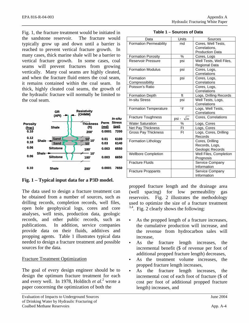
Factors Affecting Fracture Conductivity
The fracture conductivity is the product of propped fracture width and the permeability of the propping agent, as illustrated in Fig. 11. The permeability of all the propping agents, sand, resin-coated sand, and the ceramic proppants, will be 200+ darcies when no stress has been applied to the propping agent. However, the conductivity of the fracture will be reduced during the life of the well because of increasing stress on the fracture, stress corrosion affecting the proppant strength, proppant crushing, proppant embedment into the formation, and damage due to gel residue or fluid loss additives.
The effective stress on the propping agent is the difference between the in-situ stress and the flowing pressure in the fracture, as illustrated in Fig. 12. As the well is produced, the effective stress on the propping agent will normally increase because the value of the flowing bottom hole pressure will be decreasing. However, as can be seen by examining Eq. 1, the in-situ stress will decrease with time as the reservoir pressure declines. This phenomenon of decreasing in-situ stress as the reservoir pressure declines was proven conclusively by Salz.8 In shallow coal seam reservoirs, the effective stress on the propping agent is always low and does not normally affect the fracture conductivity.
•••• The stress on proppant (PThe stress on proppant (PThe stress on proppant (PThe stress on proppant (Pefefefefffff)))) incrincrincrincreaseseaseseaseseases as the flowing bottomhole pressureas the flowing bottomhole pressureas the flowing bottomhole pressureas the flowing bottomhole pressuredecreasesdecreasesdecreasesdecreases
Fig. 13 illustrates the differences is fracture conductivity vs. increasing effective stress on the propping agent for a variety of commonly used
Evaluation of Impacts to Underground Sources June 2004 of Drinking Water by Hydraulic Fracturing of Coalbed Methane Reservoirs App. A-14
EPA 816-R-04-003 Appendix AHydraulic Fracturing White Paper
Evaluation of Impacts to Underground Sources June 2004of Drinking Water by Hydraulic Fracturing ofCoalbed Methane Reservoirs App. A-15
propping agents. The data in Fig. 13 clearly showthat for shallow wells, where the effective stressis less than 4000 psi, sand can be used to createhigh conductivity fractures. As the effectivestress increases to larger and larger values, thenthe higher strength, more expensive proppingagents must be used to create a high conductivityfracture.
2,000 4,000 6,000 8,000 10,000
100
1,000
10,000
Frac
ture
Con
duct
ivity
, md
-ft
Effective Stress, psi
LWP
ISP 1
ISP+
Bauxite
RCS
Jordan Sand
RCS(300 F)
2,000 4,000 6,000 8,000 10,000
100
1,000
10,000
Frac
ture
Con
duct
ivity
, md
-ft
Effective Stress, psi
LWP
ISP 1
ISP+
Bauxite
RCS
Jordan Sand
RCS(300 F)
Fig. 13 – Effect of stress on conductivity.
6. Fracture Treatment Design
Data Requirements
In Section 1 of this paper, the data required bythe engineer to design a hydraulic fracturetreatment was discussed. The data were dividedinto two groups: (1) data that must be measuredor estimated and (2) data that can be controlled bythe design engineer. The primary data that can becontrolled by the engineer are the wellcompletion details, treatment volume, padvolume, injection rate, fracture fluid viscosity,fracture fluid density, fluid loss additives,propping agent type, and propping agent volume.
As stated earlier, the most important data are (1)the in-situ stress profile, (2) formationpermeability, (3) fluid loss characteristics, (4)
total fluid volume pumped, (5) propping agenttype and amount, (6) pad volume, (7) fracturefluid viscosity, (8) injection rate, and (9)formation modulus. The two most importantparameters are the in-situ stress profile and thepermeability profile of the zone to be stimulatedand the layers of rock above and below the targetzone.
There is a structured methodology followed bythe engineer to design, optimize, execute,evaluate and re-optimize the fracture treatmentsin any reservoir. The first step is always theconstruction of a complete and accurate data set.Table 1 lists the sources for the data required torun fracture propagation and reservoir models.Notice that the design engineer must be capableof analyzing logs, cores, production data, welltest data, and digging through well files to obtainall the information needed to design and evaluatea well that is hydraulically fracture treated.
Design Procedures
To design the optimum treatment, the engineermust determine the effect of fracture length andfracture conductivity upon the productivity andthe ultimate recovery from the well. As in allengineering problems, sensitivity runs need to bemade to evaluate uncertainties, such as formationpermeability and drainage area. In coal seamreservoirs, uncertainties can also exist in variablessuch as the gas content and the desorption rate.The production data obtained from the reservoirmodel should be used in an economics model todetermine the optimum fracture length andconductivity. Then a fracture treatment must bedesigned using a P3D fracture propagation modelto achieve the desired length and conductivity atminimum cost. The most important concept is todesign a fracture using all data and appropriatemodels that will result in the optimum economicbenefit to the operator of the well.
A P3D hydraulic fracture propagation modelshould be run to determine what needs to be
EPA 816-R-04-003 Appendix A Hydraulic Fracturing White Paper
mixed and pumped into the well to achieve the optimum values of propped fracture length and Gas WellGas Well
fracture conductivity. The base data set should be used to make a base case run. Then, the
LessLessLess 225ºF225ºF225ºF MoreMoreMore
engineer determines which variables are the most uncertain. Many times, the values of in-situ stress, modulus, permeability, fluid loss coefficient, for example, are not known with certainty and have to be estimated. The design engineer acknowledges these uncertainties and makes sensitivity runs with the P3D model to determine the effect of these uncertainties on the design process. As databases are developed, the number and magnitude of the uncertainties will diminish. In effect, the design engineer should fracture treat the well many times on his or her computer screen. Making these sensitivity runs will (1) lead to a better design and (2) educate the design engineer on how certain variables affect the ultimate values of both the created and the propped fracture dimensions. Such designs will be comprehensive, will consider uncertainties, and will be developed using professional processes.
Fracturing Fluid Selection
A critical decision by the design engineer is the selection of the fracture fluid for the treatment. Economides et al. 24 developed a flow chart that can be used to select the category of fracture fluid on the basis of factors such as reservoir temperature, reservoir pressure, the expected value of fracture half-length, and a determination if the reservoir is water sensitive. Their fluid selection flow chart for a gas well is presented in Fig. 14.
Most productive coal seam reservoirs are less than 5000 ft deep. The permeability in highly cleated coal seams decreases with increasing depth and overburden stress. At depths greater than about 5000 ft, in most cases, the coal seam does not have enough permeability to be economically developed.
No Yes
Less More150ºF
B or T X-Linked Guar/HPG
Low Pressure or Water Sensitive
Foamed Fluids
70-75 Quality or Low pH X-Linked
+ 25% CO
2
NoNo YesYes
LessLess MoreMore150ºF150ºF
B or TX-LinkedGuar/HPG
B or TX-LinkedGuar/HPG
Low Pressureor Water Sensitive
Low Pressureor Water Sensitive
FoamedFluids
70-75 Qualityor Low pHX-Linked
+25% CO
FoamedFluids
70-75 Qualityor Low pHX-Linked
+25% CO
2
No Yes
Linear Fluids
k w > 1000 md-ft + x > 300 ftNoNo YesYes
Linear FluidsLinear Fluids
k w > 1000 md-ft + x > 300 ftk w > 1000 md-ft + x > 300 ft
Because most productive coal seams are shallow, low temperature reservoirs, then the choice of fracturing fluid (according to Fig. 14) will be (1) N2 foam for low pressure reservoirs, (2) linear water based fluids if all you need is a short, low conductivity fracture, or (3) cross-linked gel if you need a wide or long fracture. Holditch et al.14 discussed the criteria for selecting a fracturing fluid in the Gas Research Institute’s Coal Seam Stimulation Manual.
For thick highly cleated coals, a crosslinked fluid should be used to create wide fractures and place as much proppant as possible in the fractures close to the wellbore. The purpose of the treatment is to link up the cleats to the wellbore using the hydraulic fracture and the proppant. The fluid should use the minimum amount of gel possible and breaker should be used to minimize damage to the fracture, and to assist in cleanup.
If the fracture is intended to connect up several thin coal seams that are vertically scattered up and down the wellbore, then coil tubing can be used to selectively stimulate each coal seam. Fig. 15 illustrates how coil tubing can be used to stimulated multiple intervals, one at a time.
Evaluation of Impacts to Underground Sources June 2004 of Drinking Water by Hydraulic Fracturing of Coalbed Methane Reservoirs App. A-16
EPA 816-R-04-003 Appendix A Hydraulic Fracturing White Paper
g g g • Single or multiple fracturing stimulation using coiled
tubing as a conduit for both the isolation and the treatment.
Bottom Hole Assembly
Fig. 15 – Fracturing using coil tubing.
In low-pressure coal seams, N2 foam can be used as the fracture fluid. Foamed fracture fluids will create wide fractures, can transport the propping agent, and are easier to clean up than fluids that do not contain N2.
Propping Agent Selection
Economides et al. 24 also produced a flow chart for selecting propping agents. Their chart is included as Fig. 16. Because most productive coal seams are shallow, sand is always used as the propping agent. In certain cases, where proppant flow back becomes a problem, then resin-coated sand is sometimes used. Special care must be used to design such treatments, because at low temperature, it may be difficult to get the resin to set and to create the consolidated sand pack needed to prevent proppant flow back.
Less
Sand
RCS
Less
More
Less More
More
ISP
250ºF
12,000 psi
6,000 psi
HSB
LessLess
SandSand
RCSRCS
LessLess
MoreMore
LessLess MoreMore
MoreMore
ISPISP
250ºF250ºF
12,000 psi12,000 psi
6,000 psi6,000 psi
HSBHSB
Fig. 16 - Proppant selection based on closure pressure.
To determine the optimum fracture conductivity, the design engineer should use the dimensionless conductivity (Cr) concept published by Cinco-Ley 25.
C LKP f
ri Eq. 2wk f
where w is the fracture width (ft), kf is the proppant permeability (md), k is the formation permeability (md), and Lf is the fracture half-length. To minimize the pressure drop down the fracture, the value of Cr should be approximately equal to ten (10).
For example, in a coal seam, if the formation permeability is 25 md, and the optimum fracture half-length is 50 ft, then the optimum fracture conductivity would be 3,927 md-ft. The engineer needs to design the treatment to create a fracture wide enough, and pump proppants at concentrations high enough to achieve the high conductivity required to optimize the treatment.
Some engineers tend to compromise fracture length and conductivity in an often-unsuccessful attempt to prevent damage to the formation around the fracture. Holditch26 showed that substantial damage to the formation around the fracture can be tolerated as long as the optimum fracture length and conductivity are achieved. Ideally, the design engineer can create the optimum fracture length and conductivity while minimizing damage to the formation. If the opposite occurs, that is, the formation is not damaged, but the fracture is not long enough or conductive enough, then the well performance will be disappointing.
The operator of the well should always evaluate the risks such as mechanical risks, product price risks and geologic risks. Uncertainties in the input data can be evaluated by making sensitivity runs using both the reservoir models and the
Evaluation of Impacts to Underground Sources June 2004 of Drinking Water by Hydraulic Fracturing of Coalbed Methane Reservoirs App. A-17
EPA 816-R-04-003 Appendix A Hydraulic Fracturing White Paper
NPV
/ IN
VN
PV /
INV
fracture propagation models. One of the main risks in hydraulic fracturing is that the entire treatment will be pumped and/or paid for (i.e. the money is spent), but for whatever reason, the well does not produce at the desired flow rates nor recovers the expected cumulative recovery. Many times, mechanical problems with the well or the surface equipment cause the treatment to fail. Other times, the reservoir does not respond as expected.
To evaluate the risk of mechanical or reservoir problems, the design engineer can use 100% of the costs on only a fraction of the revenue in the economic analyses. For example, say one (1) in every five (5) fracture treatments in a certain formation is not successful. Then one can use 80% of the expected revenue and 100% of the expected costs to determine the optimum fracture length. An illustration of how such an analyses can alter the desired fracture length is presented in Fig. 17.
Finally, after the optimum, risk adjusted fracture treatment has been designed, it is extremely important to be certain the optimum design is pumped correctly into the well. For this to occur, the design engineer and the service company
should work together to provide quality control before, during and after the treatment is pumped. The best engineers tend to spend sufficient time in the office to design the treatment correctly, then go to the field to help supervise the field operations (or provide on-site advice to the supervisor).
7. Post-Fracture Well Behavior
The original fracture treatments in the 1950’s were designed to increase well productivity. These treatments were normally pumped to remove damage in moderate to high permeability wells. McGuire and Sikora27 and Prats28
published equations that were used for many years to design fracture treatments that resulted in desired folds of increase in the productivity index of a well. The productivity index of an oil well is
oJ = q
(p − pwf ) Eq. 3
e
and for a gas well is
µ z J = (p
qg
− p 2 ) Eq. 42 e wf
J is the productivity index in terms of barrels per psi per day or mcf per psi squared per day. The viscosity and compressibility are included in the equation for productivity index of a gas well, because they are pressure dependent.
Assuming J is the productivity index for a fractured well at steady state flow, and Jo is the productivity index of the same well under radial flow conditions, Prats28 found that
Evaluation of Impacts to Underground Sources June 2004 of Drinking Water by Hydraulic Fracturing of Coalbed Methane Reservoirs App. A-18
EPA 816-R-04-003 Appendix A Hydraulic Fracturing White Paper
ln
re Group 1 – Direct far field techniques
Direct far field methods are comprised of J rw Eq. 5
= tiltmeter fracture mapping and microseismic J reo
fracture mapping techniques. These techniques require delicate instrumentation that has to be
ln 5.0 Lf
emplaced in boreholes surrounding and near the well to be fracture treated. When a hydraulic fracture is created, the expansion of the fracture will cause the earth around the fracture to deform. Tiltmeters can be used to measure the deformation and to compute the approximate direction and size of the created fracture. Surface tiltmeters are placed in shallow holes surrounding the well to be fracture treated and are best for determining fracture orientation and approximate size. Downhole tiltmeters are placed in vertical wells at depths near the location of the zone to be fracture treated. As with surface tiltmeters, downhole tiltmeter data can be analyzed to determine the orientation and dimensions of the created fracture, but are most useful for determining fracture height. Tiltmeters have been used on an experimental basis to map hydraulic fractures in coal seams.11
Microseismic fracture mapping relies on using a downhole receiver array of accelerometers or geophones to locate microseisms or microearthquakes that are triggered by shear slippage in natural fractures surrounding the hydraulic fracture. The principle of microseismic fracture mapping29 is illustrated in Fig. 18. In essence, noise is created in a zone surrounding the hydraulic fracture. Using sensitive arrays of instruments, the noise can be monitored, recorded, analyzed and mapped.
for a well containing an infinite conductivity fracture whose fracture half-length is Lf. Prats found that a well with a fracture half-length of 100 ft will produce as if the well had been drilled with a 100 ft diameter drill bit. In other words, the hydraulic fracture, if conductive enough, acts to extend the wellbore and stimulate flow rate from the well. If the dimensionless fracture conductivity, Cr (Eq. 2), is equal to 10 or greater, the hydraulic fracture will essentially act as if it is an infinately conductive fracture.
In coal seam reservoirs, the gas diffuses through the coal into the cleat system. If the cleat system is poorly developed and the permeability of the coal is low (<<1md), then the coal reservoir will probably not be economic to produce because it is almost impossible to create long, conductive fractures in thin coal seams. Thus, most commercial coal seam reservoirs are highly cleated, moderate permeability (5md<k<100md) reservoirs. As such, short, conductive fractures are required and large volumes of fluids are not needed to stimulate highly cleated coal seam reservoirs. The object of a hydraulic fracture in a highly cleated coal seam is to connect the cleat system with the well bore using the hydraulic fracture fluids and proppants.
8.0 Fracture Diagnostics
Fracture diagnostics involves analyzing the data before, during and after a hydraulic fracture treatment to determine the shape and dimensions of both the created and propped fracture. Fracture diagnostic techniques have been divided into several groups.29
Evaluation of Impacts to Underground Sources June 2004 of Drinking Water by Hydraulic Fracturing of Coalbed Methane Reservoirs App. A-19
EPA 816-R-04-003 Appendix AHydraulic Fracturing White Paper
Evaluation of Impacts to Underground Sources June 2004of Drinking Water by Hydraulic Fracturing ofCoalbed Methane Reservoirs App. A-20
LeakoffRegion
TipRegion
ElasticWavesEmmited
Receiver Detects GroundMotion From Microseism
IncreasedPore Pressure
NaturalFracture
AddedShear
LeakoffRegion
TipRegion
ElasticWavesEmmited
Receiver Detects GroundMotion From Microseism
IncreasedPore Pressure
NaturalFracture
AddedShear
Fig. 18 – Principle of microseismic fracturemapping.
Tiltmeters have been used extensively in the oiland gas industry for more than 10 years, althoughit has only been recent that the technology hasbeen available to look at fractures at depthsgreater than 4,000ft. Current surface tiltmetertechnology can see below 10,000ft.Microseismic monitoring has traditionally beentoo expensive to be used on anything but researchwells, but its cost has dropped dramatically in thepast few years, so although still expensive (on theorder of $50,000 to $100,000), it is being usedmore commonly throughout the industry. Aswith all monitoring and data collectiontechniques, however, the economics of marginalwells makes it difficult to justify any extraexpense. If the technology is used at thebeginning of the development of a field, however,the data and knowledge gained are often used onsubsequent wells, effectively spreading out thecosts.
Group 2 – Direct near-wellbore techniques
Direct near-wellbore techniques are run in thewell that is being fracture treated to locate orimage the portion of fracture that is very near(inches) the wellbore. Direct near-wellboretechniques consist of tracer logs, temperaturelogging, production logging, borehole imagelogging, downhole video logging, and caliper
logging. If a hydraulic fracture intersects thewellbore, these direct near-wellbore techniquescan be of some benefit in locating the hydraulicfracture.
However, these near-wellbore techniques are notunique and can not supply information on the sizeor shape of the fracture once the fracture is 2-3wellbore diameters in distance from the wellbore.In coal seams, where multiple fractures are likelyto exist, the reliability of these direct near-wellbore techniques are even more speculative.As such, very few of these direct near-wellboretechniques are used on a routine basis to look fora hydraulic fracture.
Group 3 – Indirect fracture techniques
The indirect fracture techniques consist ofhydraulic fracture modeling of net pressures,pressure transient test analyses, and productiondata analyses. Because the fracture treatmentdata and the post-fracture production data arenormally available on every well, the indirectfracture diagnostic techniques are the mostwidely used methods to determine the shape anddimensions of both the created and the proppedhydraulic fracture.
The fracture treatment data can be analyzed witha P3D fracture propagation model to determinethe shape and dimensions of the created fracture.The P3D model is used to history match thefracturing data, such as injection rates andinjection pressures. Input data, such as the in-situstress and permeability in key layers of rock canbe varied (within reason) to achieve a historymatch of the field data.
Post-fracture production and pressure data can beanalyzed using a 3D reservoir simulator toestimate the shape and dimensions of the proppedfracture. Values of formation permeability,fracture length and fracture conductivity can bevaried in the reservoir model to achieve a historymatch of the field data.
EPA 816-R-04-003 Appendix A Hydraulic Fracturing White Paper
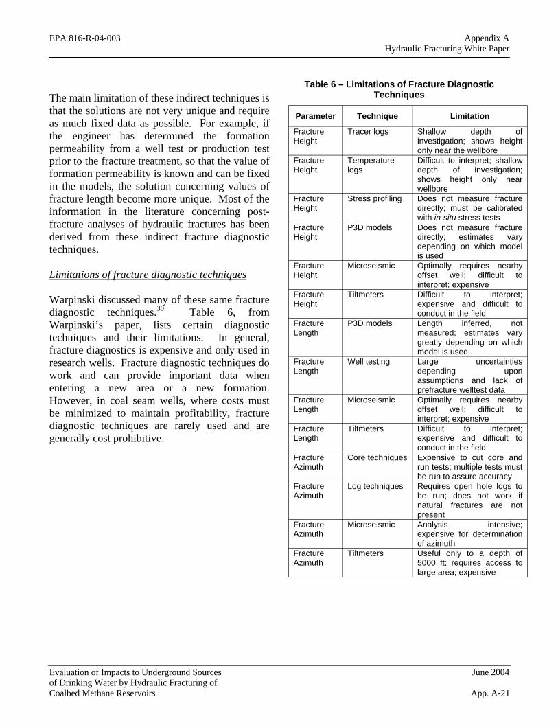
Table 6 – Limitations of Fracture Diagnostic Techniques The main limitation of these indirect techniques is
that the solutions are not very unique and require as much fixed data as possible. For example, if the engineer has determined the formation permeability from a well test or production test prior to the fracture treatment, so that the value of formation permeability is known and can be fixed in the models, the solution concerning values of fracture length become more unique. Most of the information in the literature concerning post-fracture analyses of hydraulic fractures has been derived from these indirect fracture diagnostic techniques.
Limitations of fracture diagnostic techniques
Warpinski discussed many of these same fracture diagnostic techniques.30 Table 6, from Warpinski’s paper, lists certain diagnostic techniques and their limitations. In general, fracture diagnostics is expensive and only used in research wells. Fracture diagnostic techniques do work and can provide important data when entering a new area or a new formation. However, in coal seam wells, where costs must be minimized to maintain profitability, fracture diagnostic techniques are rarely used and are generally cost prohibitive.
Parameter Technique Limitation
Fracture Tracer logs Shallow depth of Height investigation; shows height
only near the wellbore Fracture Temperature Difficult to interpret; shallow Height logs depth of investigation;
shows height only near wellbore
Fracture Stress profiling Does not measure fracture Height directly; must be calibrated
with in-situ stress tests Fracture Height
P3D models Does not measure fracture directly; estimates vary depending on which model is used
Fracture Microseismic Optimally requires nearby Height offset well; difficult to
interpret; expensive Fracture Tiltmeters Difficult to interpret; Height expensive and difficult to
conduct in the field Fracture Length
P3D models Length inferred, not measured; estimates vary greatly depending on which model is used
Fracture Well testing Large uncertainties Length depending upon
assumptions and lack of prefracture welltest data
Fracture Microseismic Optimally requires nearby Length offset well; difficult to
interpret; expensive Fracture Tiltmeters Difficult to interpret; Length expensive and difficult to
conduct in the field Fracture Core techniques Expensive to cut core and Azimuth run tests; multiple tests must
be run to assure accuracy Fracture Azimuth
Log techniques Requires open hole logs to be run; does not work if natural fractures are not present
Fracture Microseismic Analysis intensive; Azimuth expensive for determination
of azimuth Fracture Tiltmeters Useful only to a depth of Azimuth 5000 ft; requires access to
large area; expensive
Evaluation of Impacts to Underground Sources June 2004 of Drinking Water by Hydraulic Fracturing of Coalbed Methane Reservoirs App. A-21
EPA 816-R-04-003 Appendix A Hydraulic Fracturing White Paper
1. Gidley et al.: Recent Advances in Hydraulic Fracturing, SPE Monograph 12, Richardson, Texas, (1989), 1
2. Holditch, S.A. et al.: “The Optimization of Well Spacing and Fracture Length in Low Permeability Gas Reservoirs”, paper SPE 7496 presented at the 1978 SPE Annual Technical Conference and Exhibition, Houston, Oct. 1-4.
3. Veatch, R.W., Jr.: “Overview of Current Hydraulic Fracture Design and Treatment Technology – Part I”, JPT (April 1983) 677-87.
4. Britt, L.K.: “Optimized Oilwell Fracturing of Moderate-Permeability Reservoirs”, paper SPE 14371 presented at the 1985 SPE Annual Technical Conference and Exhibition, Las Vegas, Sept. 22-25.
5. Gidley et al.: Recent Advances in Hydraulic Fracturing, SPE Monograph 12, Richardson, Texas, (1989), 57
6. Hubbart, M.K. and Willis,D.G.: “Mechanics of Hydraulic Fracturing”, Trans., AIME (1957) 210, 153.
7. Whitehead, W. S., Hunt, E. R., and Holditch, S. A.: "The Effects of Lithology and Reservoir Pressure on the In-Situ Stresses in the Waskom (Travis Peak) Field," SPE 16403 presented at the 1987 Low Permeability Reservoir Symposium in Denver, CO, May 18-19.
8. Salz, L.B.: “Relationship Between Fracture Propagation Pressure and Pore Pressure”, paper SPE 6870 presented at the 1977 SPE Annual Technical Conference and Exhibition, Denver, Oct. 7-12.
9. Veatch, R. W. Jr. and Moschchovidis, Z. A.: “An Overview of Recent Advances in Hydraulic Fracturing Technology”, paper SPE 14085 presented at the 1986 International Meeting on Petroleum Engineering, Beijing, March 17-20,
10. Gidley et al.: Recent Advances in Hydraulic Fracturing, SPE Monograph 12, Richardson, Texas, (1989), 62-63
11. Nielsen, P. E. and Hanson, M. E.: “Analysis and Implications of Three Fracture Treatments in Coals at the USX Rock Creek Site Near Birmingham, Alabama”, paper presented at the 1987 Coalbed Methane Symposium, Tuscaloosa, AL (Nov. 16-19, 1987).
12. Gidley et al.: Recent Advances in Hydraulic Fracturing, SPE Monograph 12, Richardson, Texas, (1989), 341
13. Gidley et al.: Recent Advances in Hydraulic Fracturing, SPE Monograph 12, Richardson, Texas, (1989), 58
14. Holditch, S. A., Ely, J. W., and Carter, R. H.: "Development of a Coal Seam Fracture Design Manual," paper 8976 presented at the 1989
Evaluation of Impacts to Underground Sources June 2004 of Drinking Water by Hydraulic Fracturing of Coalbed Methane Reservoirs App. A-22
EPA 816-R-04-003 Appendix A Hydraulic Fracturing White Paper
Coalbed Methane Symposium in Tuscaloosa, AL, April 17-20.
15. Howard, G. C. and Fast, C. R.: “Optimum Fluid Characteristics for Fracture Extension”, Drilling and Production Practice, New York, API, (1957) 24, 261-270 (Appendix by E.D. Carter).
16. Perkins, T.K. and Kern, L.R.: “Widths of Hydraulic Fractures,” JPT, (September 1961) 13, No. 9, 937-949.
17. Geertsma, J. and de Klerk, F.: “A Rapid Method of Predicting Width and Extent of Hydraulically Induced Fractures”, JPT, (December 1969) 21, 1571-1581.
18. Nordgren, R.P.: “Propagation of a Vertical Hydraulic Fracture”, SPE Journal, (August 1972) 12, No. 8, 306-314.
19. Daneshy, A. A.: “On the Design of Vertical Hydraulic Fractures”, JPT (January 1973) 83-93; Trans., AIME, 255.
20. Geertsma, J. and Haafkens, R.: “A Comparison of the Theories to Predict Width and Extent of Vertical, Hydraulically Induced Fractures”, Trans., AIME (March 1979) 101, 8.
21. Gidley et al.: Recent Advances in Hydraulic Fracturing, SPE Monograph 12, Richardson, Texas, (1989), 95
22. Gidley et al.: Recent Advances in Hydraulic Fracturing, SPE Monograph 12, Richardson, Texas, (1989), 131
23. Holditch, S. A.: “Criteria of Propping Agent Selection”, prepared for the Norton Company (1979a).
24. Economides, M.J. and Nolte, K.G.: Reservoir Stimulation, Third Edition, John Wiley & Sons, LTD, West Sussex, England, 2000.
25. Cinco-Ley, H., Samaniego-V., F. and Dominquez, N.: “Transient Pressure Behavior for a Well with a Finite-Conductivity Vertical Fracture”, SPE Journal (August 1978) 18, 253-264.
26. Holditch, S. A.: "Factors Affecting Water Blocking and Gas Flow From Hydraulically Fractured Gas Wells," Journal of Petroleum Technology, (Dec. 1979) pp. 1515-1524.
27. McGuire, W.J. and Sikora, V.T.: “The Effect of Vertical Fractures on Well Productivity”, JPT (October 1960) 12, 72-74; Trans. AIME (1960) 219, 401-403.
29. Cipolla, C. L. and Wright, C. A.: “State-of-the-Art in Hydraulic Fracture Diagnostics”, SPE paper 64434 presented at the SPE Asia Pacific Oil and Gas Conference held in Brisbane, Australia (Oct. 16-18, 2000).
30. Warpinski, Norman R.: “Hydraulic Fracture Diagnostics”, Journal of Petroleum Technology, (Oct. 1996) pp. 907-910.
Evaluation of Impacts to Underground Sources June 2004 of Drinking Water by Hydraulic Fracturing of Coalbed Methane Reservoirs App. A-23