38
APPENDIX A7.1-1 SHIELDING ASSESSMENT FOR THE MODULAR VAULT DRY STORE

APPENDIX A7.1-1
SHIELDING ASSESSMENT FOR THE MODULAR VAULT DRY STORE

FSV ISFSI SAR Revision 2
ii
Intentionally Blank
FSV ISFSI SAR Revision 2
iii
Appendix A7.1-1
SHIELDING ASSESSMENT FOR THE MODULAR VAULT DRY STORE
TABLE OF CONTENTS
A7.1.1 Introduction
A7.1.2 Radiation Source Data
A7.1.3 Radiation Shielding Design Features
A7.1.4 Calculational Methods and Parameters
A7.1.5 Detailed Description of Calculations
A7.1.6 Radiological Release Assessment
A7.1.7 Shielding Design for Handling the Californium Neutron Sources
A7.1.8 References
Tables
Figures

FSV ISFSI SAR Revision 2
iv
LIST OF TABLES
A7.1-1 Gamma Energy Spectra for a Standard Fuel Element.
A7.1-2 Neutron Energy Spectra for a Standard Fuel Element.
A7.1-3 Polynomial Coefficients for Calculating Gamma Flux to Dose Rate Conversion
Factors.
A7.1-4 Gamma Flux to Dose Rate Conversion Factors.
A7.1-5 Polynomial Coefficients for Calculating Neutron Flux to Dose Rate Conversion
Factors.
A7.1-6 Neutron Flux to Dose Rate Conversion Factors.
A7.1-7 Material Composition Data (Percentage by Weight) for Shielding Analyses.
A7.1-8 Dose Rates Adjacent to Transfer Cask Containing Neutron Sources on the Trailer.
A7.1-9 Dose Rates Above the Transfer Cask Containing Neutron Sources at the CLUP.
A7.1-10 Dose Rates Adjacent to the CHM Containing Neutron Sources.

FSV ISFSI SAR Revision 2
v
LIST OF FIGURES
A7.1-1 Fort St. Vrain Fuel Block Model.
A7.1-2 Fort St. Vrain Spent Fuel Transfer Cask Model.
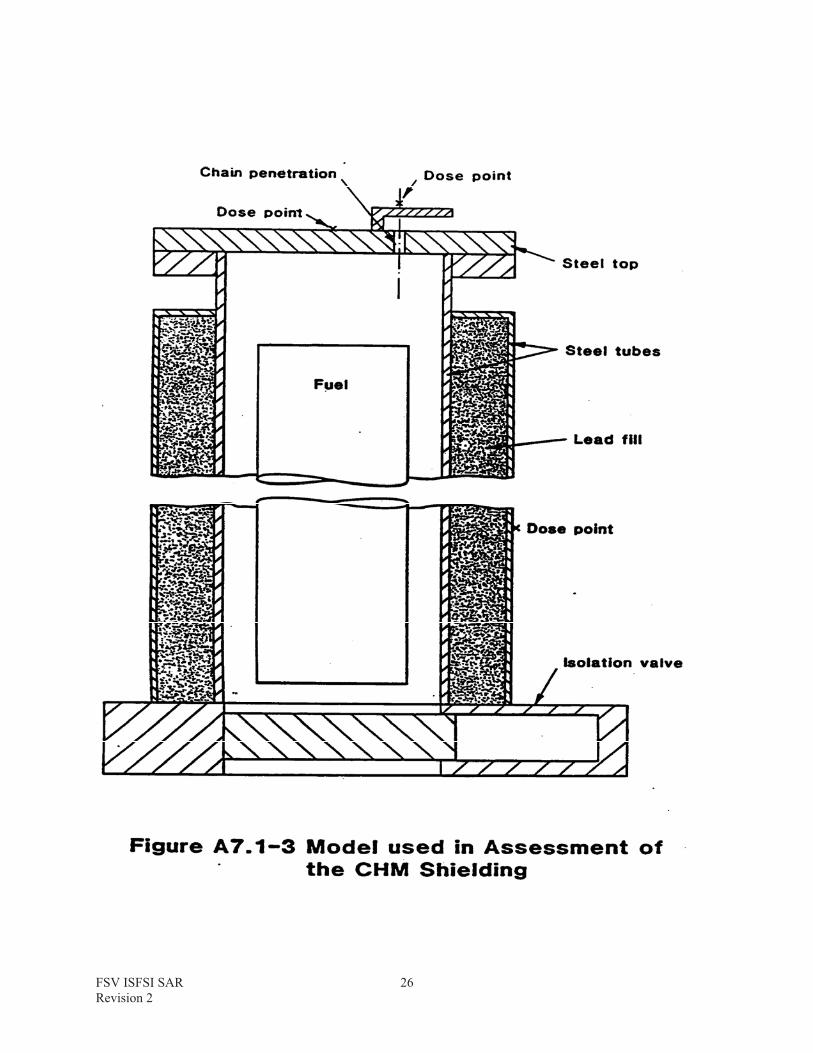
A7.1-3 Model Used in Assessment of the CHM Shielding.
A7.1-4 Model Used to Assess Shielding of Cooling Air Inlet Duct.
A7.1-5 Model Used to Assess Shielding of Cooling Air Outlet Duct
A7.1-6 Transfer Cask Containing Neutron Sources on Trailer.
A7.1-7 Transfer Cask Containing Neutron Sources at CLUP.
A7.1-8 Neutron Sources in the CHM.

FSV ISFSI SAR Revision 2
vi
INTENTIONALLY BLANK

FSV ISFSI SAR Revision 2
1
A7.1.1 INTRODUCTION
This Appendix provides details of the shielding assessment undertaken on the Modular Vault Dry Store (MVDS) for the Fort St. Vrain Independent Spent Fuel Storage Installation (ISFSI).The design caters for the Fort St. Vrain HTGR standard fuel elements, the control elements, the reflector elements and the neutron source containing fuel elements.
A detailed description of the facility layout and the operational procedures may be found in Sections 1, 4 and 5 of this Safety Analysis Report.
The first section of this Appendix describes the radiation source data used in the shielding assessment. This is followed by a brief discussion of the main radiation shielding design feature incorporated in the Fort St. Vrain MVDS. A detailed description of analytical methods then follows, as an introduction to the section which provides details of specific calculation models.
An assessment of the radiological consequences resulting from the bounding accident case of an airborne release from an FSC in the vault is dealt with in Section A7.1.6.
The shielding is designed to protect the operators during the loading, maintenance, storage, transfer and unloading of the 247 FSC’s which contain fuel and control elements. One FSC may contain the six neutron sources and for this one time operation a series of special shielding measures will be taken to ensure that doses comply with ALARA.
A7.1.2 RADIATION SOURCE DATA
A7.1.2.1 Gamma and Neutron Source Terms
The gamma and neutron source terms for an average rated fuel element for a range of decay times is presented in Section 7.2. The gamma and neutron source term spectra for the average rated fuel element are given in Tables A7.1-1 and A7.1-2, respectively.
A7.1.2.2 Source Geometry
The model used to present the Fort St. Vrain fuel element is illustrated in Figure A7.1-1. The hexagonal fuel element is modeled as a cylinder with the same cross section area. The fuel and graphite are represented as a single homogeneous material, and the composition and density are presented on Table A7.1-1. The fuel source term is uniformly distributed throughout the inner active region, shown on Figure A7.1-1.
A7.1.2.3 Flux to Dose Rate Conversion Factors
Gamma and neutron flux to dose rate conversion factors have been taken from Reference A7.1-1, and are described below.
A7.1.2.3.1 Gamma Flux to Dose Rate Conversion Factors
The general form of the analytic function is

FSV ISFSI SAR Revision 2
2
1n Dfg(E) = A + Bx + Cx2 + Dx3
where Dfg(E) = gamma flux to dose rate conversion factor (rem hr-1)/(photon cm-2s-1)E = gamma energy (MeV) x = 1n E
The coefficients of the polynomial expression are given in Table A7.1-3. Resultant gamma flux to dose rate conversion factors appropriate to the fuel block gamma source spectrum used in the shielding assessment are given in Table A7.1-4.
A7.1.2.3.2 Neutron Flux to Dose Rate Conversion Factors
As in gamma radiation, the general form of the analytic function is:
1n Dfn(E) = A + Bx + Cx2 + Dx3
where Dfn(E) = neutron flux to dose rate conversion factor (rem hr-1)/(neutron cm-2s-1)E = neutron energy (MeV) x = 1n E
The coefficients of the polynomial expression are given in Table A7.1-5. Resultant neutron flux dose rate conversion factors appropriate to the neutron source spectrum used in the shielding assessment are given in Table A7.1-6.
A7.1.3 RADIATION SHIELDING DESIGN FEATURES
For the purposes of this radiation shielding design analysis, the Fort St. Vrain MVDS has been considered to be comprised of the following major components.
a) The Shielded Transfer Cask (TC) b) The Cask Load/Unload Port (CLUP) c) The Container Handling Machine (CHM) d) The Auxiliary Handling Machinery e) The Vault Module (VM) bulk shield, consisting of:
i) the main concrete shield walls ii) the cooling air inlet and outlet ducts iii) the concrete and steel Charge Face Structure (CFS) iv) the vault shield plugs in the CFS
The general arrangements of these components are shown in Figures 1.1-1 and 1.1-2 of this Safety Analysis Report. The significant shielding design features are described below.

FSV ISFSI SAR Revision 2
3
A7.1.3.1 The Shielded Transfer Cask
The Fort St. Vrain MVDS has been designed to interface with the standard HTGR transfer cask (Reference A7.1-10), illustrated for shielding purposes in Figure A7.1-2.
To facilitate MVDS operations the lid of the Fuel Storage Container (FSC), has been modified to incorporate a removable depleted uranium shield plug. This inner shield plug has been designed to ensure that the dose rates adjacent to the TC when handling 600 day decay spent fuel are no greater than the dose rates that prevail adjacent to the original TC lid, when the cask contains fuel at 100 days decay. This approach is in keeping with the ALARA concept.
A7.1.3.2 The Cask Load/Unload Port (CLUP)
The CLUP is described in detail in Section 4.4.2.2 of this Safety Analysis Report. It essentially consists of a penetration in the floor between the Transfer Cask Reception Bay and the Charge Hall in which the TC is retained during loading/unloading of the Fuel Storage container. The CLUP is designed so that the shielding envelope around the FSC is maintained during TC lid and uranium plug insertion/removal operations and during the transfer of the FSC between the TC and the CHM.
The main features included to maintain the shielding envelope are; an inner shield ring located in the cask lid, an outer shield ring enclosing the top of the cask and an isolation valve to shield the charge hall against direct radiation from the top of an FSC.
A7.1.3.3 The Container Handling Machine (CHM)
The CHM is described in detail in Section 4.4.2.5 of this Safety Analysis Report. It essentially consists of three components; the FSC Raise/Lower mechanism assembly, the CHM structure and the CHM isolation valve. The main shielding features are shown in Figure A7.1-3.
The raise/lower mechanism incorporates two pairs of chain wheels, for a dual link chain, mounted on the 5" thick steel shield plate at the top of the CHM. Each of these, and the chain penetration through the top plate, are individually enclosed by a ½ thick steel box to give adequate shielding.
The main CHM structure consists of concentric inner and outer steel tubes of 1" and 0.25" wall thicknesses respectively with the annular interstitial gap being filled with 5.5" of lead. This radial shield region gives adequate shielding from the fuel during transportation between the CLUP and the vault. The inner steel tube extends 15" above the main shielding of the CHM structure, to the CHM top plate.
The CHM Isolation Valve is a steel structure designed on the principle of a gate-valve and comprises a main body of 76" diameter by 15.5" thick with a central penetration of 22.5" diameter, thus giving a radial steel shielding thickness of 26". Within this body the gate is 11" thick and when closed overlaps the valve penetration by a minimum of 1". This CHM valve is

FSV ISFSI SAR Revision 2
4
mounted on the bottom of the CHM structure, and completes the shielding envelope when transporting fuel at the vault.
A7.1.3.4 The Auxiliary Handling Machinery
The auxiliary Handling Machinery consist of two discrete handling machines; the Uranium Shield Plug Handling Device and the Shield Plug Handling Devic.
The Uranium Shielding Plug Handling Device (USPHD), is designed to maintain an adequate shielding envelope around the transfer cask while the Uranium Shield is manipulated on the cask at the CLUP. The USPHD comprises a frame of 1" steel consisting of a base and a 12.9" high annular cylindrical body. Around the body there is a bulk shielding envelope of lead which is 5.5" above the top of the frame. The shielding envelope is a square profile with sides measuring 31.25".
The Shield Plug Handling Device (SPHD) is designed to maintain adequate shielding above a fuel storage penetration while manipulating the Shield Plug. As with the above device the frame is 1" thick steel but the bulk shielding used is concrete which has a square profile with its sides measuring 36" and is concurrent with the top of the frame, at a height of 40.7".
A7.1.3.5 The Charge Face Isolation Valve
The Charge Face Isolation Valve is of a similar design to the CHM Isolation Valve, described in Section A7.1.3.3 above. This valve is designed to act as an interface between the Charge Face Structure and the Handling Machinery, and to minimize operator dose rates during loading/unloading of the fuel into a vault channel. The base plate of this valve has a pattern of circular recesses which are designed to interlace with the pattern of the shield plug caps protruding above the Charge Face upper surface. This design eliminates any direct streaming paths between the Valve and the Charge Face.
A7.1.3.6 Vault Module Bulk Shield
The Fort St. Vrain fuel blocks were supplied to the MVDS in sealed FSC’s, which were then loaded into the vault module. Shielding for the fuel in these containers was provided by the main concrete shield walls, the concrete filled Charge Face Structure, the shield plugs and the Air Inlet and Outlet ducts, with their collimator slabs.
A7.1.3.6.1 Concrete Shield Walls
The concrete shield walls around the outside of the vault structure are all 3'6" thick, with the Air Inlet and Outlet ducts discussed in detail in Section A7.1.3.6.2 below. The thickness of the Internal Walls between each vault module are designed only to meet structural requirements.
The Outer (north) End Wall has an additional shielding feature, that of the Storage Well facility which consists of a solid concrete wall running the height of the FSC array and extending out

FSV ISFSI SAR Revision 2
5
from the main shield wall. This additional feature has three storage well positions which are 3'6" from the outside face of the shield wall and of 2'4" diameter.
The Inner (south) End Wall also has additional shielding features, that of the TCRB structure which has a concrete wall thickness of 2'0".
A7.1.3.6.2 Air Inlet and Outlet Ducts
The Air Inlet and Outlet Ducts are designed to enable a buoyancy driven cooling air flow to pass over the FSC array in the vault module, but not to the detriment of the shielding requirements.
The Inlet duct is of labyrinth design so as to eliminate direct unshielded radiation and minimize the effect of scattered radiation. In addition to this concrete collimator slabs are included to further reduce the direct and the scattered radiation dose outside the Inlet duct. The collimator slabs are 6" thick by 3'0" wide and spaced typically on a 12" pitch.
A similar approach is adopted for the Outlet duct, although in this instance a “dog-leg” bend is incorporated, rather than the labyrinth provided in the Inlet duct. The Outlet duct collimators are also 6" thick by 3'0" wide and are spaced typically on a 18" pitch.
A7.1.3.6.3 The Charge Face Structure
The Charge Face Structure is described in detail in Section 4.2.3.2, of this Safety Analysis Report. It consists of a 2" thick steel top plate fixed to a 2" thick steel bottom plate by an array of, steel liner tubes, into which the FSC’s are located. The resultant interstitial cavity is 38" deep and filled with concrete. The side walls of the CFS which run parallel to the vault side walls are supported in a step in the vault concrete structure, and are mortared into place. The end wall of the CFS adjacent to the Inlet and Outlet duct’s are clear of the concrete vault structure and are stepped to eliminate direct shine paths for radiation.
A7.1.3.6.4 The Vault Shield Plug
The Vault Shield Plugs maintain the integrity of the Charge Face Structure shielding. They consist of a stepped cylindrical blocks of Cast Iron with the lower section bored out to reduce weight. This design gives a bulk shield thickness of 14" of Cast Iron. The step in the Vault Shield Plug is used to support the plug in the Charge Face Structure and also to reduce radiation streaming. This step gives a shielding thickness of 3" above the streaming path between the Charge Face Structure steel liner tube and the Vault Shield Plug.
A7.1.4 CALCULATIONAL METHODS AND PARAMETERS
A7.1.4.1 Calculation Methods
In addition to widely accepted hand calculational techniques (see, for example, References A7.1-2, 3, 4 and 5), the MVDS shielding analysis has involved the use of the computer codes described below.
FSV ISFSI SAR Revision 2
6
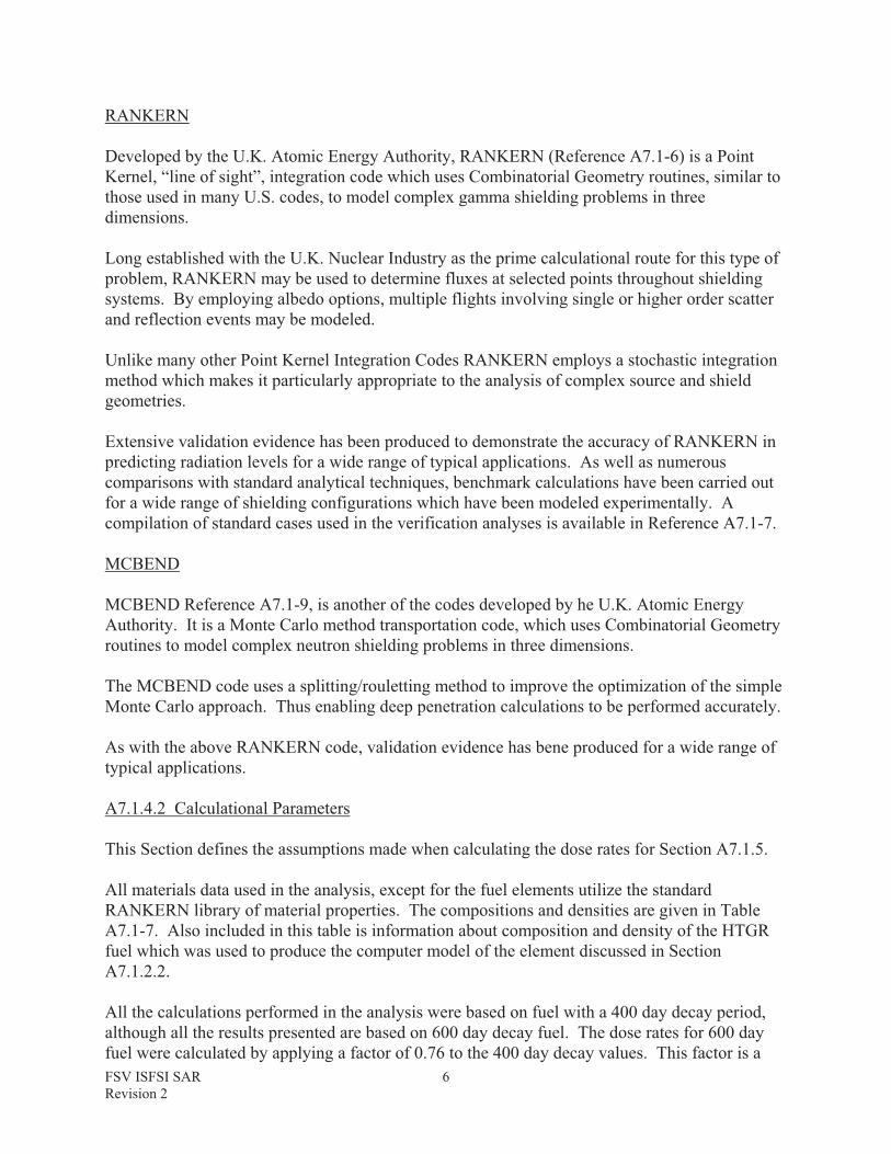
RANKERN
Developed by the U.K. Atomic Energy Authority, RANKERN (Reference A7.1-6) is a Point Kernel, “line of sight”, integration code which uses Combinatorial Geometry routines, similar to those used in many U.S. codes, to model complex gamma shielding problems in three dimensions.
Long established with the U.K. Nuclear Industry as the prime calculational route for this type of problem, RANKERN may be used to determine fluxes at selected points throughout shielding systems. By employing albedo options, multiple flights involving single or higher order scatter and reflection events may be modeled.
Unlike many other Point Kernel Integration Codes RANKERN employs a stochastic integration method which makes it particularly appropriate to the analysis of complex source and shield geometries.
Extensive validation evidence has been produced to demonstrate the accuracy of RANKERN in predicting radiation levels for a wide range of typical applications. As well as numerous comparisons with standard analytical techniques, benchmark calculations have been carried out for a wide range of shielding configurations which have been modeled experimentally. A compilation of standard cases used in the verification analyses is available in Reference A7.1-7.
MCBEND
MCBEND Reference A7.1-9, is another of the codes developed by he U.K. Atomic Energy Authority. It is a Monte Carlo method transportation code, which uses Combinatorial Geometry routines to model complex neutron shielding problems in three dimensions.
The MCBEND code uses a splitting/rouletting method to improve the optimization of the simple Monte Carlo approach. Thus enabling deep penetration calculations to be performed accurately.
As with the above RANKERN code, validation evidence has bene produced for a wide range of typical applications.
A7.1.4.2 Calculational Parameters
This Section defines the assumptions made when calculating the dose rates for Section A7.1.5.
All materials data used in the analysis, except for the fuel elements utilize the standard RANKERN library of material properties. The compositions and densities are given in Table A7.1-7. Also included in this table is information about composition and density of the HTGR fuel which was used to produce the computer model of the element discussed in Section A7.1.2.2.
All the calculations performed in the analysis were based on fuel with a 400 day decay period, although all the results presented are based on 600 day decay fuel. The dose rates for 600 day fuel were calculated by applying a factor of 0.76 to the 400 day decay values. This factor is a

FSV ISFSI SAR Revision 2
7
conservative estimate of the differential decay and thus actual doses to operators will be less than this.
A7.1.5 DETAILED DESCRIPTION OF CALCULATIONS
This section describes in detail, the shielding calculations carried out for the major components of the Fort St. Vrain MVDS shielding system, as identified in Section A7.1.3 of this Safety Analysis Report.
A7.1.5.1 The Shielded Transfer Cask
The Transfer Cask used to transfer the fuel to and from the MVDS is the Fort St. Vrain Transfer Cask.
The assessment of the radiation levels associated with the Shielded Transfer Cask was performed using RANKERN, and was divided into three discrete models, as illustrated in Figure A7.1-2.
The modeling of the base of the Cask was carried out using a single fuel element with 11.6" of steel situated on one end face. The gamma dose rate calculated on the outer surface of the steel was 42 mrem/hour.
The modeling of the side of the Cask was carried out using two fuel elements surrounded by concentric cylinders of 1.25" of steel, then 3.5" of depleted Uranium, then 1.0" of steel. The gamma dose rate calculated on the outer surface was 36 mrem/hour.
The modeling of the top of the Cask was carried out using a single fuel element shielded by a 10.75" thick steel slab, containing within it a 4.25" slab of depleted Uranium. The gamma dose rate on the outer surface of the cask top was calculated to be 0.4 mrem/hour in the center rising to a local peak of 5.7 mrem/hour near the edge.
A7.1.5.2 The Container Handling Machine
The assessment of radiation levels associated with the Container Handling Machine presents the dose rates through the side and the top of the CHM.
The assessment of the radiation level through the side shield was performed using the RANKERN code and the model used is illustrated in Figure A7.1-3. In the assessment the FSC itself was neglected, as it only has a nominal shielding thickness, and only two fuel blocks were modeled as dose rate contributions from any further blocks above or below these two were shown to be negligible. The shield model consisted of three concentric annular regions around the fuel of 1.0" of steel, 5.5" of lead and 0.25" of steel. This analysis gives gamma dose rates of 65 mrem/hour on contact with the side of the CHM and 25 mrem/hour at a typical operator position (nominally 6'0" from centerline of CHM).
In the assessment at the top of the CHM a model of the FSC grapple was included to give more representative geometry, this resulted in the modeling of all plates and bars greater than 0.5" steel thickness. The model is illustrated in Figure A7.1-3. The gamma dose rate through the top

FSV ISFSI SAR Revision 2
8
of the CHM was found to be 21 mrem/hour through the bulk shield plate and 92 mrem/hour at the closest accessible region above the chain penetrations.
An assessment of the neutron radiation contribution from a standard fuel element to the dose rate was carried out using the MCBEND code. The assessment through the side of the CHM, gave a neutron dose rate of 0.5 mrem/hour, which is negligible compared to the gamma dose rate.
A7.1.5.3 Auxiliary Handling Machinery
The application of the Auxiliary Handling Machinery at the MVDS is different for each item, and thus calculational models for this equipment are described separately.
A7.1.5.3.1 Uranium Shield Plug Handling Device
The Uranium Shield Plug Handling Device is used at the CLUP in conjunction with the Port Isolation Valve (which is identical to the Charge Face Isolation Valve). The model used for the Uranium Shield manipulation assessment includes the top of the Cask with the closure removed and the empty FSC Lid, below this level are the fuel elements. Above the cask top the model of the isolation valve includes a 15.5" thick steel plate with a 22.5" diameter penetration and a 23" square by 11" thick penetration centrally located around the circular penetration.
The model of the Handling Device above this penetration includes a 1" thick steel base plate with a 1" thick steel cylindrical body to a height of 12.9" above the base plate. This is surrounded by a concentric square lead body of a 31.25" side and 18.4" above the base plate.Within the steel body, located near the bottom, is the Uranium shield of 18.5" diameter and 5.1" thick. The gamma dose rate was calculated at various locations around the lead shielding and the peak dose was found to be 7 mrem/hour at the bottom corner of the lead shield.
A7.1.5.3.2 Shield Plug Handling Device
The Shield Plug Handling Device is used in conjunction with the Charge Face Isolation Valve to remove and replace the channel Shield Plug. The model of this situation incorporates a fuel element with an empty FSC lid above it. Around and above the top of the fuel, is a model of single CFS channel incorporating two 2" steel plates with 38" of concrete between, surrounding a 1" steel liner tube. On top of the channel is the Isolation Valve model and then the Shield Plug Handling Device model as described previously in Section A7.1.5.3.1, except that the bulk shielding consists of a 36" square of concrete to a height of 41", and includes a shield plug within as described in Section A7.1.3.6.4. The gamma dose rate was calculated at various positions around the bulk shielding and the peak was found to be 7 mrem/hour.
A7.1.5.4 Vault Module Concrete Walls
The direct penetration radiation shielding assessment of the Vault Module concrete Walls was undertaken in the following four cases:-
FSV ISFSI SAR Revision 2
9
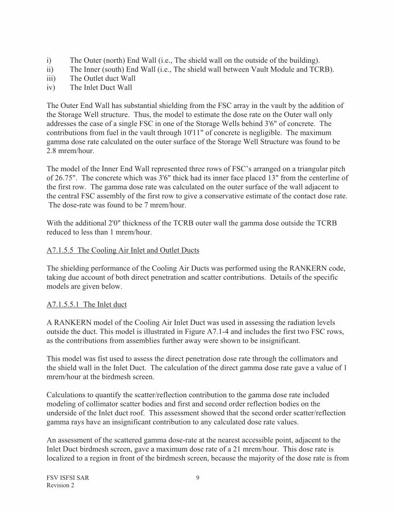
i) The Outer (north) End Wall (i.e., The shield wall on the outside of the building). ii) The Inner (south) End Wall (i.e., The shield wall between Vault Module and TCRB). iii) The Outlet duct Wall iv) The Inlet Duct Wall
The Outer End Wall has substantial shielding from the FSC array in the vault by the addition of the Storage Well structure. Thus, the model to estimate the dose rate on the Outer wall only addresses the case of a single FSC in one of the Storage Wells behind 3'6" of concrete. The contributions from fuel in the vault through 10'11" of concrete is negligible. The maximum gamma dose rate calculated on the outer surface of the Storage Well Structure was found to be 2.8 mrem/hour.
The model of the Inner End Wall represented three rows of FSC’s arranged on a triangular pitch of 26.75". The concrete which was 3'6" thick had its inner face placed 13" from the centerline of the first row. The gamma dose rate was calculated on the outer surface of the wall adjacent to the central FSC assembly of the first row to give a conservative estimate of the contact dose rate. The dose-rate was found to be 7 mrem/hour.
With the additional 2'0" thickness of the TCRB outer wall the gamma dose outside the TCRB reduced to less than 1 mrem/hour.
A7.1.5.5 The Cooling Air Inlet and Outlet Ducts
The shielding performance of the Cooling Air Ducts was performed using the RANKERN code, taking due account of both direct penetration and scatter contributions. Details of the specific models are given below.
A7.1.5.5.1 The Inlet duct
A RANKERN model of the Cooling Air Inlet Duct was used in assessing the radiation levels outside the duct. This model is illustrated in Figure A7.1-4 and includes the first two FSC rows, as the contributions from assemblies further away were shown to be insignificant.
This model was fist used to assess the direct penetration dose rate through the collimators and the shield wall in the Inlet Duct. The calculation of the direct gamma dose rate gave a value of 1 mrem/hour at the birdmesh screen.
Calculations to quantify the scatter/reflection contribution to the gamma dose rate included modeling of collimator scatter bodies and first and second order reflection bodies on the underside of the Inlet duct roof. This assessment showed that the second order scatter/reflection gamma rays have an insignificant contribution to any calculated dose rate values.
An assessment of the scattered gamma dose-rate at the nearest accessible point, adjacent to the Inlet Duct birdmesh screen, gave a maximum dose rate of a 21 mrem/hour. This dose rate is localized to a region in front of the birdmesh screen, because the majority of the dose rate is from

FSV ISFSI SAR Revision 2
10
scattered radiation. Access to this region is limited by an exclusion fence around the Inlet Duct and the dose rate outside the fence is 1.3 mrem/h.
A7.1.5.5.2 The Outlet Duct
The RANKERN model of the Cooling Air Outlet Duct is illustrated in Figure A7.1-5. It includes the FSC assembly array, the collimators and the bulk shield wall.
This model assesses the direct penetration gamma dose rate on the outer surface of the bulk shield wall of 2 mrem/hour. Dose rates were also calculated on the outside surface of the Outlet duct above the 19 feet level and the peak dose directly through the structure was found to be 5 mrem/hour.
An assessment was made of the gamma dose rate passing up the full height of the Outlet duct to the canopy. This was carried out by the introduction of reflection bodies around the “dog-leg” bend. The peak dose-rate at the top of the Outlet duct (+80'6" level) is less than 1 mrem/hour. Therefore, any dose rate contribution to ground level figures from the Outlet Duct is negligible.
A7.1.5.5 The Charge Face Structure
The combination of the concrete filled Charge Face Structure and the Shield Plugs serves two purposes from the radiological point of view:
i) The provision of bulk shielding from the FSC array. ii) Attenuation of radiation from the FSC array streaming up through the clearance gaps
between the shield plugs and the penetrations in the CFS.
The assessment of the direct penetration dose rate through the bulk shielding of the Charge Face Structure and Shield Plugs assembly was assessed as follows. First, a RANKERN model of a single channel was produced which represented the fuel, the FSC Lid, a Shield Plug and a Section of the Charge Face Structure, which consists of 2" thick steel top and bottom plates, with 38" of concrete between, around a steel liner tube. The gamma dose rate on contact with the top surface of the shield plug is 0.2 mrem/hour.
An assessment for the whole Charge Face Structure was then carried out which involved repeating the above model on a 26.75" pitch triangular array. The dose rate on contact with the CFS midway between three adjacent channels is also 0.2 mrem/hour.
An assessment of the radiation streaming dose along the gap between the Shield plug and the steel liner tube was carried out. By using the RANKERN models described above, the dose rate on the underside of the Charge Face Structure was calculated. From this value and the dimensions of the annular gap the streaming dose rate penetrating through the 3" cap of the Shield Plug was calculated. This gives a gamma dose rate of 30 mrem/hour which is localized in an annular region typically 0.06" wide.
A7.1.6 RADIOLOGICAL RELEASE ASSESSMENT
FSV ISFSI SAR Revision 2
11
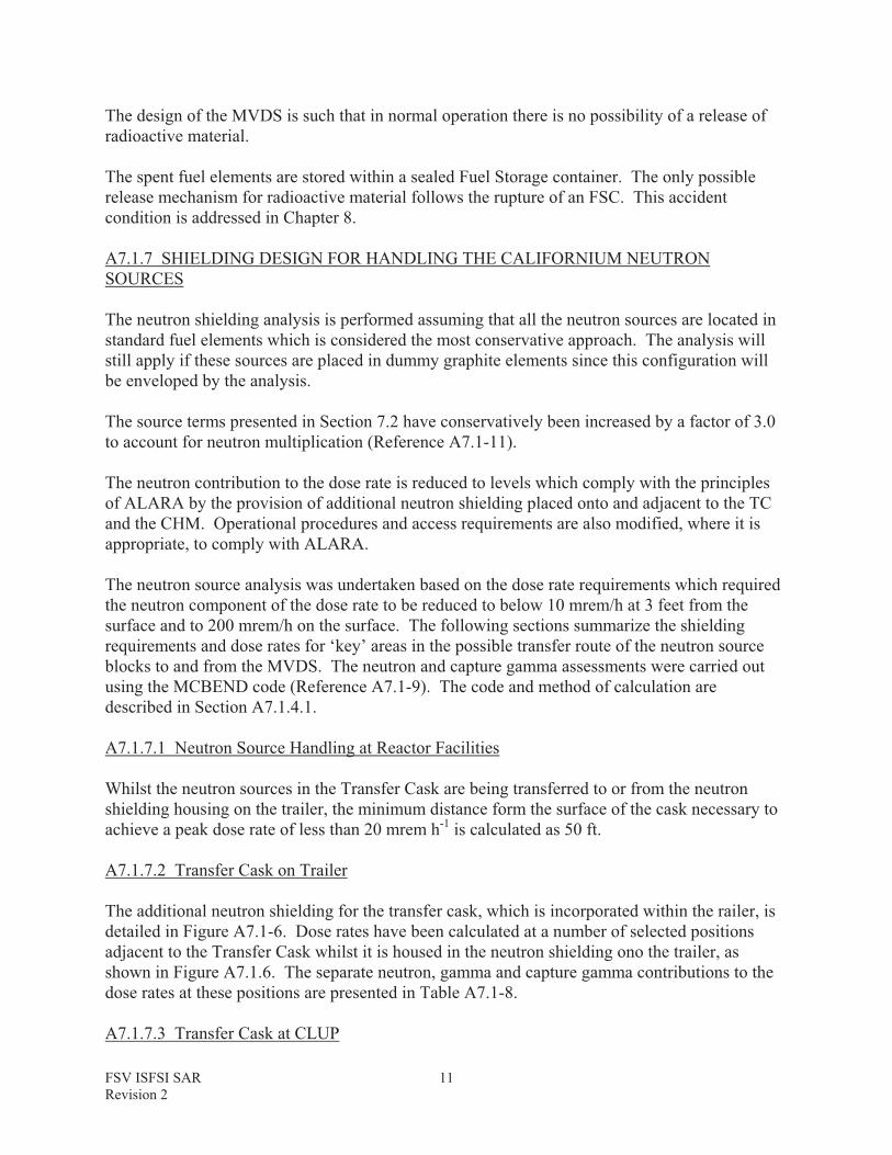
The design of the MVDS is such that in normal operation there is no possibility of a release of radioactive material.
The spent fuel elements are stored within a sealed Fuel Storage container. The only possible release mechanism for radioactive material follows the rupture of an FSC. This accident condition is addressed in Chapter 8.
A7.1.7 SHIELDING DESIGN FOR HANDLING THE CALIFORNIUM NEUTRON SOURCES
The neutron shielding analysis is performed assuming that all the neutron sources are located in standard fuel elements which is considered the most conservative approach. The analysis will still apply if these sources are placed in dummy graphite elements since this configuration will be enveloped by the analysis.
The source terms presented in Section 7.2 have conservatively been increased by a factor of 3.0 to account for neutron multiplication (Reference A7.1-11).
The neutron contribution to the dose rate is reduced to levels which comply with the principles of ALARA by the provision of additional neutron shielding placed onto and adjacent to the TC and the CHM. Operational procedures and access requirements are also modified, where it is appropriate, to comply with ALARA.
The neutron source analysis was undertaken based on the dose rate requirements which required the neutron component of the dose rate to be reduced to below 10 mrem/h at 3 feet from the surface and to 200 mrem/h on the surface. The following sections summarize the shielding requirements and dose rates for ‘key’ areas in the possible transfer route of the neutron source blocks to and from the MVDS. The neutron and capture gamma assessments were carried out using the MCBEND code (Reference A7.1-9). The code and method of calculation are described in Section A7.1.4.1.
A7.1.7.1 Neutron Source Handling at Reactor Facilities
Whilst the neutron sources in the Transfer Cask are being transferred to or from the neutron shielding housing on the trailer, the minimum distance form the surface of the cask necessary to achieve a peak dose rate of less than 20 mrem h-1 is calculated as 50 ft.
A7.1.7.2 Transfer Cask on Trailer
The additional neutron shielding for the transfer cask, which is incorporated within the railer, is detailed in Figure A7.1-6. Dose rates have been calculated at a number of selected positions adjacent to the Transfer Cask whilst it is housed in the neutron shielding ono the trailer, as shown in Figure A7.1.6. The separate neutron, gamma and capture gamma contributions to the dose rates at these positions are presented in Table A7.1-8.
A7.1.7.3 Transfer Cask at CLUP

FSV ISFSI SAR Revision 2
12
There are no neutron shielding requirements above the transfer cask whilst at the CLUP. This situation may be achieved by the placement of the larger neutron sources at the bottom of the FSC. Dose rates have been calculated at the top of the Transfer Cask whilst it is positioned at the CLUP for various shielding configurations, as shown in Figure A7.1.7. The neutron, gamma and capture gamma contributions to the dose rates at these positions are presented in Table A7.1-9.
A7.1.7.4 Transfer to and from CHM
There are no neutron shielding requirements for the isolation valve. Transient dose rates have been calculated adjacent to the isolation valves whilst the neutron sources are in transit between the CLUP and the CHM and between the CHM and the vault. The maximum transient neutron dose rate calculated on the surface of the isolation valve is 88 mrem/h-1. The gamma and capture gamma contributions to dose rates at this point are found to be eligible. The minimum distance from the edge of the valve required to achieve a peak transient dose rate of 10 mrem h-1 is calculated as 7 ft.
A7.1.7.5 CHM
The neutron shielding requirements for the CHM are detailed in Figure A7.1.8. Dose rates have been calculated at a number of selected positions adjacent to the CHM whilst it contains the six neutron sources. The neutron, gamma and capture gamma contributions to the dose rates at these positions are presented in Table A7.1-10.

FSV ISFSI SAR Revision 2
13
A7.1.8 REFERENCES
A7.1-1. ANSI/ANS-6.1.1-1977; “Neutron and Gamma-ray Flux-to-Dose-Rate Factors”. A7.1-2. “Engineering Compendium on Radiation Shielding”; Ed. E. P. Blizard; Springer
Verlag 1975. A7.1-3. “Reactor Shielding Design Manual”; T. Rockwell; McGraw Hill, 1956. A7.1-4. “Fundamental Aspects of Reactor Shielding”; H. Goldstein; Pergamon Press,
1959.A7.1-5. “Gamma Ray Transmission Through Finite Slabs”; G. H. Peebles; Rand
Corporation R-240; December 1952.
A7.1-6. “RANKERN A Point Kernel Integration Code for Complicated Geometry Problems; User Guide to Version 12", Issue 2, September 1987. ANSWERS (RANK)2; UKAEE Winfrith, UK.
A7.1-7. “RANKERN - Verification of Version 12"; Issue 1, 1989; ANSWERS (RANKERN)2; UKAEE Winfrith, UK.
A7.1-8. Health Physics Vol. 38 (April) 1980, pp 543-621; “Dose Rate Conversion Factors for External Exposure to Photon and Electron Radiation from Radionuclides Occurring in Routine Releases from Nuclear Fuel Cycle Facilities”.
A7.1-9. “MCBEND - A Monte Carlo Program for Shielding Calculations; User Guide to Version 6", issue 4, March 1990. Answers (MCBEND) 2: UKAEA Winfrith, UK.
A7.1-10. “Design Report for the Model FSV-1A Package”, GADR55, Volume II.
A7.1-11. “FSV ISFSI Predicted Spent Fuel Fission Product Inventories” General Atomics Report No. GA910061.

FSV ISFSI SAR Revision 2
14
TABLE A7.1-1 GAMMA ENERGY SPECTRA FOR A STANDARD FUEL ELEMENT
Gamma Spectra (Photons/s) Gamma Energy
Boundaries(MeV)Mean 400 Day 600 Day 900 Day
4.0 - 3.5 3.75 3.03E05 2.11E05 1.24E05
3.5 - 3.0 3.25 6.62E08 4.54E08 2.58E08
3.0 - 2.6 2.80 1.50E10 1.45E10 1.45E10
2.6 - 2.2 2.40 4.45E10 2.90E10 1.53E10
2.2 - 1.8 2.00 2.34E12 1.44E12 6.95E11
1.8 - 1.34 1.57 4.02E12 3.08E12 2.14E12
1.34 - 0.92 1.13 9.06E12 7.47E12 5.90E12
0.92 - 0.38 0.65 3.47E14 2.68E14 2.11E14
0.38 - 0.22 0.30 2.57E13 1.72E13 1.03E13
0.22 - 0.12 0.17 8.92E08 8.93E08 9.82E08
Total 3.88E14 2.97E14 2.30E14
The source strength derivation is given in Section 7.2.1.
FSV ISFSI SAR Revision 2
15
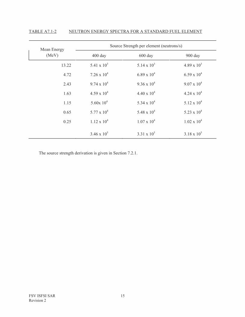
TABLE A7.1-2 NEUTRON ENERGY SPECTRA FOR A STANDARD FUEL ELEMENT
Source Strength per element (neutrons/s) Mean Energy
(MeV) 400 day 600 day 900 day
13.22 5.41 x 10³ 5.14 x 10³ 4.89 x 10³
4.72 7.26 x 10⁴ 6.89 x 10⁴ 6.59 x 10⁴
2.43 9.74 x 10⁴ 9.36 x 10⁴ 9.07 x 10⁴
1.63 4.59 x 10⁴ 4.40 x 10⁴ 4.24 x 10⁴
1.15 5.60x 10⁴ 5.34 x 10⁴ 5.12 x 10⁴
0.65 5.77 x 10⁴ 5.48 x 10⁴ 5.23 x 10⁴
0.25 1.12 x 10⁴ 1.07 x 10⁴ 1.02 x 10⁴
3.46 x 10⁵ 3.31 x 10⁵ 3.18 x 10⁵
The source strength derivation is given in Section 7.2.1.

FSV ISFSI SAR Revision 2
16
TABLE A7.1-3 POLYNOMIAL COEFFICIENTS FOR CALCULATING GAMMA FLUX TO DOSE RATE CONVERSION FACTORS
Photon Energy (MeV)
A B C D
0.01 to 0.03 -2.0477x101 -1.7454 0 -2.4897x10⁻¹
0.03 to 0.5 -1.3626x101 -5.7117x10⁻¹ -1.0954 0
0.5 to 5.0 -1.3133x101 7.2008x10⁻¹ -3.3603x10² 0
5.0 to 15.0 -1.2791x11 2.8309x10⁻¹ 1.0873x10⁻¹ 0
The data are taken from Reference A7.1-1.
FSV ISFSI SAR Revision 2
17
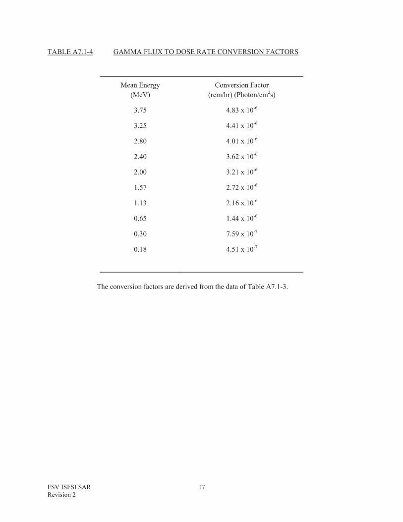
TABLE A7.1-4 GAMMA FLUX TO DOSE RATE CONVERSION FACTORS
Mean Energy (MeV)
Conversion Factor (rem/hr) (Photon/cm2s)
3.75 4.83 x 10⁻⁶
3.25 4.41 x 10⁻⁶
2.80 4.01 x 10⁻⁶
2.40 3.62 x 10⁻⁶
2.00 3.21 x 10⁻⁶
1.57 2.72 x 10⁻⁶
1.13 2.16 x 10⁻⁶
0.65 1.44 x 10⁻⁶
0.30 7.59 x 10⁻⁷
0.18 4.51 x 10⁻⁷
The conversion factors are derived from the data of Table A7.1-3.
FSV ISFSI SAR Revision 2
18
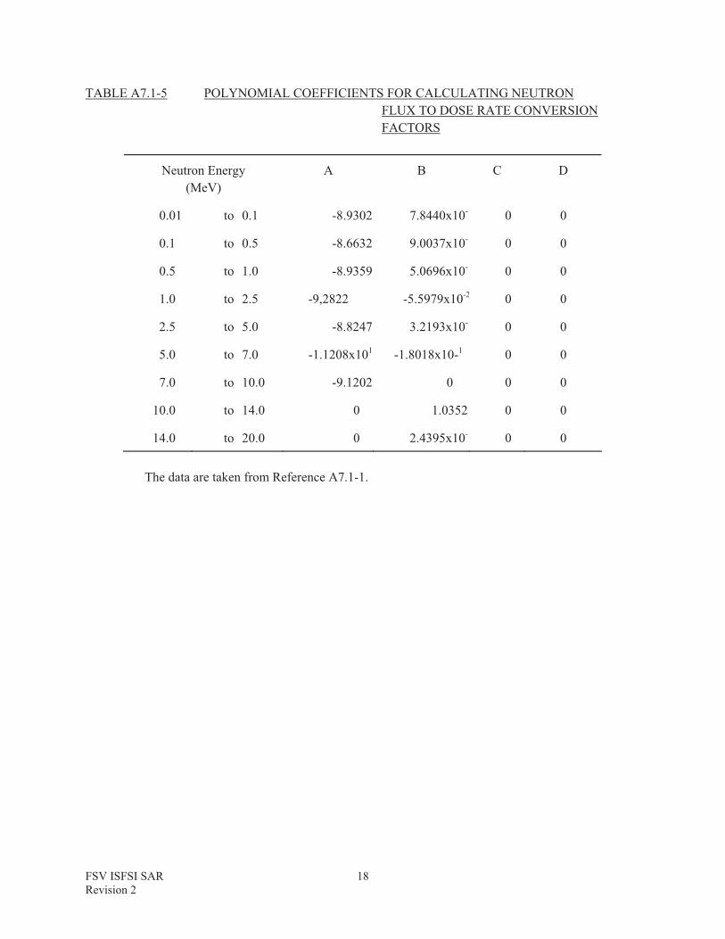
TABLE A7.1-5 POLYNOMIAL COEFFICIENTS FOR CALCULATING NEUTRON FLUX TO DOSE RATE CONVERSION FACTORS
Neutron Energy (MeV)
A B C D
0.01 to 0.1 -8.9302 7.8440x10⁻¹ 0 0
0.1 to 0.5 -8.6632 9.0037x10⁻¹ 0 0
0.5 to 1.0 -8.9359 5.0696x10⁻¹ 0 0
1.0 to 2.5 -9,2822 -5.5979x10⁻² 0 0
2.5 to 5.0 -8.8247 3.2193x10⁻¹ 0 0
5.0 to 7.0 -1.1208x101 -1.8018x10⁻¹ 0 0
7.0 to 10.0 -9.1202 0 0 0
10.0 to 14.0 0 1.0352 0 0
14.0 to 20.0 0 2.4395x10⁻¹ 0 0
The data are taken from Reference A7.1-1.

FSV ISFSI SAR Revision 2
19
TABLE A7.1-6 NEUTRON FLUX TO DOSE RATE CONVERSION FACTORS
Mean Energy (MeV)
Conversion Factor (rem/hr) (Neutron/cm2s)
13.22 1.96 x 10⁻⁴
4.72 1.53 x 10⁻⁴
2.43 1.25 x 10⁻⁴
1.63 1.28 x 10⁻⁴
1.15 1.31 x 10⁻⁴
0.65 1.06 x 10⁻⁴
0.25 4.96 x 10⁻⁵
The conversion factors are derived from the data of Table A7.1-5.

FSV ISFSI SAR Revision 2
20
TABLE A7.1-7 MATERIAL COMPOSITION DATA (PERCENTAGE BY WEIGHT) FOR SHIELDING ANALYSES
MATERIAL
Element Concrete DepletedUranium
Lead Steel FuelBlock
Polythene
H 0.40 12.1
C 6.00 90.40 64.2
O 49.80 23.2
A1 1.40 2.10
Si 15.50
S 0.20
Ca 25.70
Mn 1.50
Fe 1.00 98.50
Pb 96.00
Sb 4.00 7.00
Th 0.50
U 100.00
B 0.5
Density (g/cm3)
2.24 18.90 11.04 7.86 1.53 0.93

FSV ISFSI SAR Revision 2
21
TABLE A7.1-8 Dose Rates Adjacent to Transfer Cask Containing Neutron Sources on the Trailer
SURFACE (mrem/hour)
36" FROM SURFACE (mrem/hour)
DOSE POINT (See Figure
A7.1-6)NEUTRON GAMMA
CAPTUREGAMMA
TOTAL NEUTRON GAMMACAPTUREGAMMA
TOTAL
1 47 19 11 77 7 7 2 16
2 56 19 11 86 8 7 2 17
3 57 23 2 82 7 8 � 15
4 27 23 2 52 3 8 � 11
5 77 28 1 106 7 9 � 16
6 21 28 1 50 2 9 � 11
7 119 36 1 156 10 10 � 20
8 134 36 1 171 10 10 � 20
9 60 � 21 81 17 � 5 22

FSV ISFSI SAR Revision 2
22
TABLE A7.1-9Dose Rates Above the Transfer Cask Containing Neutron Sources at the CLUP
SURFACE (mrem/hour)
36" FROM SURFACE (mrem/hour)
DOSE POINT (See Figure
A7.1-7)NEUTRON GAMMA
CAPTUREGAMMA
TOTAL NEUTRON GAMMACAPTUREGAMMA
TOTAL
1 9 6 � 15 1 1 � 2
2 60 20 � 80 8 7 � 15

FSV ISFSI SAR Revision 2
23
TABLE A7.1-10 Dose Rates Adjacent to the CHM Containing Neutron Sources
SURFACE (mrem/hour)
36" FROM SURFACE (mrem/hour)
DOSE POINT (See Figure
A7.1-6)NEUTRON GAMMA
CAPTUREGAMMA
TOTAL NEUTRON GAMMACAPTUREGAMMA
TOTAL
1 41 38 1 80 7 16 � 23
2* 33 45 � 78 19 2 � 21
* This is not a normally accessible position.

FSV ISFSI SAR Revision 2
24

FSV ISFSI SAR Revision 2
25
FSV ISFSI SAR Revision 2
26

FSV ISFSI SAR Revision 2
27

FSV ISFSI SAR Revision 2
28

FSV ISFSI SAR Revision 2
29

FSV ISFSI SAR Revision 2
30

FSV ISFSI SAR Revision 2
31

FSV ISFSI SAR Revision 2
32
Intentionally Blank


