13
Digger Derrick Operator Safety Training A A Appendix Appendix
Digger Derrick Operator Safety Training
AAAppendixAppendix

Ap
pen
dix
A

Resources
OSHA Regulations
The following OSHA regulations form the basis of
much of the content in this safety training.
• 1910.67 – Vehicle-Mounted Elevating and Rotating
Work Platforms
• 1910.180 – Crawler Locomotive and Truck Cranes
• 1910.268 – Telecommunications
• 1910.269 – Electric Power Generation, Transmission,
and Distribution
• 1926.453 – Aerial Lifts
• 1926.550 – Cranes and Derricks
• 1926.601 – Motor Vehicles
• 1926.952 – Mechanical Equipment
Additional OSHA information is available at
www.osha.gov
ANSI A10.31 (1995)
Digger Derricks are manufactured and tested to ANSI
A10.31 standards. This standard also describes the
responsibilities of:
• Manufactures
• Distributors and installers
• Owners and users
• Lessors
• Operators
Some of the responsibilities described include opera-
tor training, operator’s manuals, and product safety haz-
ard labels.
ASME B30.5 – Mobile and Locomotive Cranes (1994)
ASME B30.6 – Derricks (1995)
These manuals contain the hand signals used by dig-
ger derrick operators. The “Extend Boom” and “Retract
Boom” signals are found in ASME B30.5 and the
remaining signals are in ASME.B30.6.
Operator Training
Operator safety training is mandatory for every individ-
ual who operates a digger derrick.
• Written training.
• Operator training on the specific digger derrick used
in the workplace, and the specific procedures and
hazards encountered in the workplace.
• Performance Evaluation in writing for each trainee.
Prewritten Performance Evaluation Sheets for each
trainee may be provided by the employer.
It is very important that trainees understand they must
complete all three steps before they operate a digger
derrick.
Safety Statements
Safety statements are one of the primary ways to call
our attention to the potential hazards associated with
digger derrick operation.
• SAFETY ALERT symbols appear with most safety
statements. It means attention, become alert, your
safety is involved!
• DANGER Symbol indicates an imminently haz-
ardous situation which, if not avoided, will result in
death or serious injury. Danger is used in the most
extreme situations.
• WARNING symbol indicates a potentially hazardous
situation which, if not avoided, could result in serious
injury or death.
• CAUTION indicates a situation that might result in a
personal injury or property damage.
Digger Derrick Operator Safety Training
DANGER
WARNING
CAUTION

• NOTICE: Symbols, if failed to follow, could cause
damage to the equipment or cause it to operate
improperly.
Product Safety Labels
Operators must read, understand, and follow the infor-
mation listed on all product safety labels and documen-
tation. The “Product Safety Label” section of the opera-
tor’s manual contains the location and line drawing of
each label. Most Product Safety Labels are generic but
they could differ slightly on different machines.
Hand Signals
When you need to communicate to an operator of a
digger derrick, use hand or radio signals to issue com-
mands. Make sure the ground worker and machine
operator stay in plain sight of each other. Hand signals
are illustrated on the following pages.
EXTEND BOOM
(Both fists in front of body with thumbs
pointing outward)
DOG EVERYTHING
(Clasp hands in front of body)
NOTICENOTICE
TRAVEL
RETRACT BOOM
(Both fists in front of body with thumbs pointing
toward each other)
EXTEND BOOM
(One Hand)
RETRACT BOOM
(One Hand )

HOIST
(With forearm vertical, forefinger pointing up, move
hand in small horizontal circle)
LOWER
(With arm extended downward, forefinger pointing
down, move hand in small horizontal circles)
USE MAIN HOIST
USE WHIP LINE
RAISE BOOM
(Arm extended, fingers closed, thumb pointing
upward)
LOWER BOOM
(Arm extended, fingers closed, thumb pointing
downward)
MOVE SLOWLY
(Use one hand to give any motion signal and place
the other hand motionless in front of hand giving
the motion signal. Hoist slowly shown as an
example.)
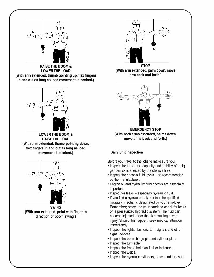
RAISE THE BOOM &
LOWER THE LOAD
(With arm extended, thumb pointing up, flex fingers
in and out as long as load movement is desired.)
LOWER THE BOOM &
RAISE THE LOAD
(With arm extended, thumb pointing down,
flex fingers in and out as long as load
movement is desired.)
SWING
(With arm extended, point with finger in
direction of boom swing.)
STOP
(With arm extended, palm down, move
arm back and forth.)
EMERGENCY STOP
(With both arms extended, palms down,
move arms back and forth.)
Daily Unit Inspection
Before you travel to the jobsite make sure you:
• Inspect the tires – the capacity and stability of a dig-
ger derrick is affected by the chassis tires.
• Inspect the chassis fluid levels – as recommended
by the manufacturer.
• Engine oil and hydraulic fluid checks are especially
important.
• Inspect for leaks – especially hydraulic fluid.
• If you find a hydraulic leak, contact the qualified
hydraulic mechanic designated by your employer.
Remember; never use your hands to check for leaks
on a pressurized hydraulic system. The fluid can
become injected under the skin causing severe
injury. Should this happen, seek medical attention
immediately.
• Inspect the lights, flashers, turn signals and other
signal devices.
• Inspect the boom hinge pin and cylinder pins.
• Inspect the turntable.
• Inspect the frame bolts and other fasteners.
• Inspect the welds.
• Inspect the hydraulic cylinders, hoses and tubes to

ensure that they are in place and show no evidence
of damage, cracks or corrosion.
• Inspect the synthetic load line and material handling
attachments for wear or damage. All material han-
dling hooks should have functional throat latching
mechanisms.
• Inspect the fiberglass boom and liners for contami-
nation, damage and scratches.
Before You Travel
When you load a truck for travel, check that:
• All items are secured.
• Bin doors are properly latched.
• Outriggers are raised and boom is stowed and
secure.
• Never exceed the Gross Vehicle Weight Rating
(GVWR).
• GVW = Truck Weight + Digger Derrick and Body
Weight + Tools and Cargo Weight.
• Check the clearance height of the vehicle relative to
the overhead obstructions such as power lines and
bridges. Preplanning your route of travel can help to
avoid these types of obstructions.
Before You Tow a Trailer
When you tow a trailer, be sure that:
• The towing vehicle pintle hook and trailer are com-
patible.
• The trailer tow bar eye conforms to S.A.E. J847 and
all local and state road requirements.
• You inspect the trailer and pintle hook for wear and
damage.
• You don’t exceed the manufacture’s rating or towing
capacity of the vehicle, pintle hook or trailer.
• You use safety chains of proper capacity in accor-
dance with locale, state and federal road require-
ments.
• All latching mechanisms are properly engaged.
• All Trailer lights and signaling devices are in place
and operational. Some loads may require additional
signaling devices depending on local, state or feder-
al requirements.
Backing
• If you must back up, ensure that your backup alarm
is operational and use a rearview mirror.
OR
• Use an observer to signal when it is safe to move.
View the observer by using a mirror or other
rearview device. Back slowly and always keep the
observer in your view.
• If you cannot see the observer, stop backing until
they return to a position where you can see them.
Parking
• If you must park on a roadway, park on the right
hand side of the road facing in the direction of traffic
flow.
• Whenever possible, leave at least fifteen (15) feet
between the edge of your vehicle and the traveled
road surface. If you must park closer, appropriate
warning devices must be used. Depending on your
employer’s recommendations, and local, state or fed-
eral requirements, this may include warning lights,
reflectors, warning signs, traffic cones, flags or a flag
person.
• Before you leave the vehicle, remember to set the
parking brake and chock the wheels.
Job Briefing
When you arrive at the job site, OSHA requires that
the employee in charge of the work, hold a job briefing
before the start of each job. The briefing must cover:
• Job Hazards.
When you conduct a job briefing, walk around the job
site and identify the location and voltage of overhead
power lines. Note that only qualified employees may
approach within ten feet of any energized line.
• Work procedures.
• Special Precautions.
When working on or near energized conductors or
equipment, be sure to use appropriate cover up proce-
dures and insulating materials and tools rated for the
line voltage. Discuss any additional potential hazards
associated with the tasks at hand.
• Energy Source Control.
• Personal protective equipment.
Your job briefing should include discussions about
personal protective equipment required by ANSI, OSHA,
and your employer which may include clothing as well

as head, eye and fall protection, insulated gloves and
sleeves, and leather gloves.
Qualified Employees
A qualified employee is one who has been designated
by their employer as trained and familiar with the safety
related work practices, procedures and other safety
requirements of OSHA which pertain to their respective
job requirement.
This includes competency in the skills and techniques
necessary to distinguish exposed live parts from other
electric equipment as well as the ability to determine the
nominal voltage of exposed live parts.
A qualified employee must also be trained and com-
petent in the skills needed to determine the minimum
approach distances specified by OSHA as well as the
special precautionary techniques, insulated tools, equip-
ment and lockout/tag out procedures necessary for
working near exposed energized parts.
Operating On Slopes
Digger Derricks manufactured and tested to ANSI
A10.31 are limited to their rated capacity with the unit
set up on a maximum of a five degree slope. Unless
appropriate measures to level the unit is taken, you
should never operate a digger derrick on a slope of over
five degrees. This is especially true of operations that
include rotation of the boom over the side of the chassis.
If the job site includes an area where the slope
exceeds five degrees, or excessive ground penetration is
observed, appropriate cribbing and blocking of outrig-
gers may be required.
Pre-Operational Inspection
A pre-operational inspection (also called pre-flight
inspection) must be performed before you use the
machine.
Remember; never exceed the unit’s rated capacity.
Overloading the derrick boom can result in structur-
al damage, instability or both.
• Check the hydraulic reservoir oil level.
• Check for hydraulic leaks.
• Check pins.
• Check fasteners.
• Check welds.
• Check hydraulic cylinders, hoses and tubes.
• Check visual and audible warning devices.
• Inspect fiberglass boom structures, platforms and
liners for dirt and damage.
• Apply the parking brake, place the wheel chocks,
start the engine and engage the power take off.
• Barricade or ground the unit if required by employer.
• Properly set all outriggers before the derrick boom is
moved from the boom rest.
* During deployment, Outriggers being extended
should be kept in full view to be sure path is
clear of other individuals.
* Outrigger pads are required on all unpaved or
soft surfaces, or in accordance with your
employer’s work practices.
* They should be set on the downhill side first and
should extend at least three to four inches after
contacting the ground. In addition, the chassis
tires should unload noticeably, but may remain
in contact with the ground.
• Perform a pre-operational check from the lower con-
trols:
* Be sure the area is free from overhead obstruc-
tions such as trees, poles and power lines.
* Operate the unit through the range of all func-
tions to ensure proper operation.
* When you operate the unit from the lower con-
trols, be sure that you and others are clear of
moving structures.
* On units equipped with platforms, test the over-
ride system at the lower control station. The
lower controls should override the function of
the upper controls.
* Return the boom to the boom rest.
* If the unit has a platform, orient the platform
near the ground for platform access.

• Perform a pre-operational check from the upper con-
trols (if equipped):
* OSHA regulations and ANSI standards require
that personal fall protection equipment be used
and attached to the unit’s fall protection anchor
points. Prior to entering the platform to test the
upper controls, be sure you are using approved
personal fall protection equipment that you have
inspected for damage.
* Make certain the upper control selector func-
tions (also called the emergency stop button)
stops system operation.
Personal Protective Equipment
Before you begin your job, check the condition of all
protective clothing and equipment as required by ANSI,
OSHA and your employer.
Sources of Insulation
• It is important to note that when working from an
insulated digger derrick, the boom is not the opera-
tor’s primary source of insulation.
• Personal protective equipment required by ANSI,
OSHA, and your employer is your primary source of
insulation. You must use proper protective equip-
ment, rated for operations within the OSHA defined
approach distances.
• When units are equipped with an insulated boom,
the upper boom should always be extended first for
dielectric protection.
Electrical Continuity of the Boom Tip
• When operating a digger derrick from a boom tip
platform, all metal components at the boom tip,
including the controls, bust be considered to be elec-
trically connected.
• If an energized conductor or object touches any part
of the boom tip, treat the entire boom tip as ener-
gized.
• If any ground conductor or object touches any part
of the boom tip, consider the entire boom tip as
grounded.
• The insulated portion of the boom can only isolate
the operator from grounding through the boom and
vehicle.
• The pole, cross arm and other hardware must be
considered by the operator as grounded.
• The unit can’t protect a person from current between
an energized conductor and any other conductor,
ground or grounded equipment on or in contact with
the pole including the neutral wire.
General Guidelines During Unit Operation
• When handling material, never attach the load to the
fall protection anchor.
• Never lay conductors on platforms to lift them into
position. And do not allow conductors or other
objects to drag across the boom as this may cause
gouges in the boom and compromise its strength,
durability, and insulating properties.
• On units equipped with side load protection, never
overload the side load protection system, as this can
cause instability and/or structural problems.
OSHA Guidelines
• Only trained persons may operate the digger derrick.
• Remember to calculate the minimum approach dis-
tances specified by OSHA for the nominal voltage of
exposed parts. Refer to OSHA Regulation 1910.269,
Tables R-6 through R-10.
• Workers should never belt off to an adjacent pole,
structure or equipment.
• Workers must always stand firmly on the floor of the
platform—never sitting or climbing on the edge of
the platform or using planks, ladders or other
devices for a work position.
• Workers should never wear climbers while working
from a digger derrick equipped with a platform.
• You may use hydraulic tools connected to boom-tip
outlets with nonconductive hoses as long as ener-
gized conductors are insulated with protective equip-
ment that is rated, maintained and tested for the
voltage involved. When the tools are not in use, but
are attached to the tool circuit outlets at the boom
tip, turn off the tool circuit.
Material Handling OSHA Guidelines
The following are OSHA requirements pertaining to
material handling:
• Operators must observe all manufacturer’s load rat-
ing and instructions.
• The rated load capacities and instructions related to
derrick operations must remain posted on the unit.
• Digger derricks and associated equipment must be
inspected by a competent person at the manufactur-
er’s set intervals. And a complete record of inspec-
tion and repairs must be maintained.
• You cannot make any modifications to a digger der-
rick which affects operation without manufacturer’s
written approval.
• The operator of a digger derrick may not leave their
position at the controls while a load is suspended.
• Synthetic ropes must be inspected in accordance
with OSHA requirements and the recommendations
of the rope manufacturer.
• When you set, move or remove poles, all necessary
precautions should be taken to avoid contact with
energized power conductors or equipment. When
poles are being placed or moved during heavy rains,
sleet or wet snow, additional safe work practices
may be required for certain workers and voltages.
• Maintain minimum approach distances form exposed
energized lines and equipment. Refer to OSHA
Regulation 1910.269 Table R-6 through R-10
• A designated person, other than the operator, may
be required to observe the approach distance to
exposed lines and equipment. The designated per-
son must give timely warnings before the minimum
approach distance required by OSHA is reached.
Avoid Contact With An Energized Power Conductor
You should take special precautions when you work
with energized power conductors or equipment:
• If the pole you are working on could come in contact
with an energized power conductor:
* Wear insulating gloves when you handle the
pole with your hand or tools.
* The truck should be considered energized and
special precautions are needed to avoid electro-
cution.
• When you are on a digger derrick vehicle, avoid all
contact with the ground, with persons standing on
the ground and with all grounded objects such as
people, tree limbs or metal sign posts.
• If you can, stay on the vehicle as long as the possi-
bility of contact with an energized power conductor
exists.
• When the digger derrick may come in contact with
energized lines, and it is necessary to leave the
vehicle:
* Step onto an insulating blanket and break all
contact with the vehicle before
hopping or shuffle stepping off the blanket onto
the ground.
* If an insulating blanket is not available, jump
cleanly from the vehicle and hop or shuffle step
away from the unit.
Avoid Contact With Energized Equipment
If you are working on equipment that could become
energized:
• The exposed lines must be covered with appropriate
insulating protective material.
OR
• Insulate the equipment for the voltage involved.
OR
• Position the equipment so that its uninsulated por-
tions cannot approach the energized lines or equip-
ment closer than the specified minimum approach
distance.
OR
• Protect each employee from hazards resulting from
equipment contact with the energized lines.
Protective measures must include:
* Using the best available ground to minimize the
time the lines remain energized.
* Bonding equipment together to minimize poten-
tial differences.
* Providing ground mats to extend to areas of
equipotential.
* Using insulating protective equipment or barri-
cades to guard against any remaining haz-
ardous potential differences.
Load Capacity OSHA Guidelines
The following are OSHA requirements pertaining to
load capacity:
• Stay within the maximum load rating and other
design limitations for the conditions under which the

work is being performed.
• Load capacities shown on the Load Capacities Chart
are for a digger derrick operating on a level surface.
• Before you lift a load, consult the Load Capacities
Chart, Jib Capacities Chart, or the Combined Use
Capacities Chart. You may also need to use the
Range Diagram to help determine which booms you
need to extend.
• The Load Capacities Chart is located near the lower
control station, the Jib Capacities Chart is located at
the platform, and the Combined Use Capacities
Chart is located near the boom tip.
* NOTE: These charts are examples, and may not
pertain specifically to all Digger Derricks.
Using The Load And Jib Capacities Charts
Notes: * The load and jib capacities charts are only
used if your digger derrick doesn’t have a
platform or the platform is unoccupied.
* These charts are only for freely suspended
loads.
To determine the load capacity of your digger derrick:
• Determine the load radius. Always measure the load
radius from the centerline of rotation of the digger
derrick to the center of the mass of the load.
* If you use a material handling Jib, make sure
you take into account the actual load radius at
the jib tip. Do not exceed the maximum load
radius shown in the Load Capacities Chart
when you lift a load with the jib.
• Determine the boom angle.
• If the actual load radius or boom angle is not shown
on the chart use the load capacity at the next longer
radius or lower boom angle.
• If a boom stage is not fully retracted, use the load
capacity for that boom when it is extended.
• Use the Load Capacities Chart to determine the
combination of booms to extend. You can also use
the Range Diagram to help determine which
boom(s) to extend.
• Use the Load Capacities Chart to determine the
load capacity at the load radius, boom angle, and
boom combination you have chosen. The load
capacity must be adjusted as follows.
• Never exceed the smallest of:
* The load capacity shown on the Load
Capacities Chart minus reductions for all
options mounted on the boom.
* The winch line rated working load multiplied by
the number of parts of line.
* When the load being lifted exceeds the rated
working load for a single part of line, multiple
parts of winch line must be used. Remember,
the weight of the load, divided by the number of
parts of line must not exceed the rated working
load of the winch line.
* The rated capacity shown on the Jib Capacities
Chart.
Combined Use Capacities Chart
• If the unit’s platform is occupied, refer to the
“Combined Use Capacities Chart” instead of the
load capacity chart.
• No load is permitted on the winch line when the per-
sonnel jib is in use.
Estimating The Weight Of A Load
• A load of unknown weight should never be lifted.
• If you aren’t sure of the weight of the load you are
attempting to lift, and you have estimated its weight,
perform a boom capacity test to lift the load a small
amount. This boom raise capacity test is described
in your Derrick Operator Manual. But remember the
boom capacity test does not test the unit’s stability.
The Load Capacities Chart must be used to deter-
mine the unit’s stability.
Hydraulic Overload Protection System
• Remember; that the Hydraulic Overload Protection
System (HOP) only protects the unit from structural
overload, not instability. As previously stated, the
Load Capacities Chart must be used to determine
the unit’s stability.
Safety Procedures For Material Handling
The following safety procedures should be observed
when you handle material.
• Never use the material handling load line to lift per-
sonnel, to lift loads over personnel or to lift loads
which are still attached or stuck to the ground.
• Never drag loads or side load the boom and never
try to override the side load protection system.
• Operate all controls smoothly and make sure
controls are returned to neutral after the desired
operation.
• Always use rigging and slings which are in good
condition and carry tags giving their rated capacity.
• Use tag lines only where appropriate.
• Never allow the load to come in contact with the
boom tip, except when placing poles using the boom
tip pole guide.
Unstowing And Using Your Auger
1. The first thing to remember is to always call your
local, and/or state digging safety, or underground
line locator, service prior to digging.
2. Before you unstow the auger, fully retract the boom.
3. Raise the boom to approximately 45 degrees.
4. Rotate the boom to a position where the potential
swing area of the auger is clear of personnel and
obstructions.
5. Carefully move the AUGER (DIGGER) control to
the DIG position with the engine at low RPM’s. This
will take up any slack in the wind up cable and
decrease the load on the auger stow latch.
6. Operate the AUGER RELEASE switch to retract the
auger stow latch.
7. Continue holding the switch in this position while
slowly actuating the DIGGER control to the CLEAN
position, carefully lowering the auger into a vertical
position.
8. When the auger has descended to its vertical posi-
tion, remove the wind up cable from the auger
flight.
9. If your unit is equipped with a two-speed digger,
select high or low speed before operating the dig-
ger. The auger must be at a complete stop before
shifting speeds.
10. Extend the boom approximately 1-1/2 feet (0.5m)
to meter the boom extension control so the auger
stays aligned. A straight hole cannot be dug if the
boom is fully extended or retracted. The boom
control is used to lower the boom as it digs.
11. Maintain enough force on the auger to keep it
moving downward at a moderate rate of speed.

Too much force may result in the auger corkscrew-
ing into the ground rather than digging and could
overload the boom and cause machine damage.
12. When you clean the auger, operate it in reverse by
putting the DIGGER control in the CLEAN posi-
tion. Use the DIGGER SHAKE switch to help
clean the digger.
Stowing The Auger
1. Attach the wind up sling.
2. Slowly raise the boom. Be sure the potential swing
area of the auger is clear of personnel and obstruc-
tions.
3. With the digger in low speed, operate the AUGER
RELEASE switch to retract the auger stow latch.
4. Continue holding the switch in this position and
move the DIGGER control to the DIG position. The
auger will begin to wind onto the sling and towards
the latch bracket.
5. Meter the DIGGER control slowly and carefully as
the auger nears the bracket. The digger has
enough power to break the cable or strap if the con-
trol is fully actuated as it is rewound.
6. Once the auger has been returned to the stow posi-
tion, disengage the AUGER RELEASE switch to
close the auger latch.
7. Meter the DIGGER control very slightly to the
CLEAN position just enough to release the stress
on the wind up cable.


![MK-A.qxd 09.12.3 0:04 PM Page 1 Rotary Clamp Cylinder New · Ι: Moment of inertia [kg·m2] m: Load mass [kg] If arms other than the options are used, be sure to calculate the moment](https://static.documents.pub/doc/80x56/5ebef5f93a822434f866233c/mk-aqxd-09123-004-pm-page-1-rotary-clamp-cylinder-new-moment-of-inertia.jpg)


