69
Appendix B Geotech Data B-1

Appendix B
Geotech Data
B-1

B -2
CONTENTS
B.1 . Geologic Data ................................................................................................................................. B-5
B-1.1 Summary of Results of the ICDF Site Visits to Examine the Sediments in the ICDF Pit ................................................................................................................... B-5
B-1.2 Results of Initial Visits to Examine the ICDF Excavation Sediments ............................. B-17
B.2 . Geotechnical Data ......................................................................................................................... B-29
B-2.1 Summary of the ICDF Pit Grade to Bedrock Interface Boreholes ................................... B-29
B-2.2
B-2.3
Drilling Core Logs ........................................................................................................... B-41
ASTM Standard D 2487, United Soil Classification System .......................................... B-58
B.3 . References ..................................................................................................................................... B-69
FIGURES
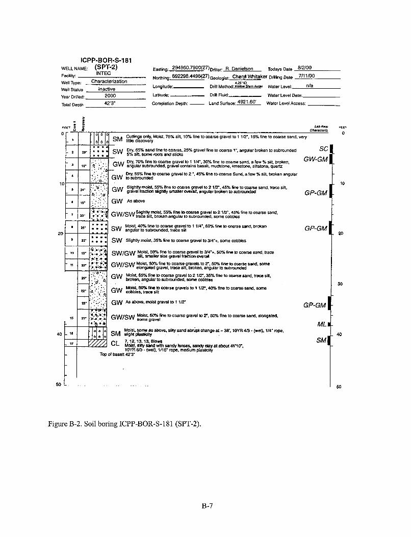
B.1 . Soil boring ICPP-BOR-$178 (GSB-1) ......................................................................................... B-6
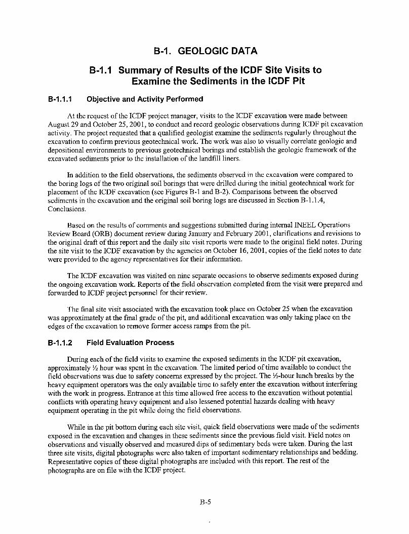
B.2 . Soil boring ICPP-BOR-S-181 (SPT-2) .......................................................................................... B-7
B.3 . Four photographs of the sediments observed in the ICDF excavation at depth of 8 to 30 ft bgs ................................................................................................................................... B-9
B.4 . Four photographs of the sediments observed in the ICDF excavation at depth of 33 to 36 ft bgs .......................................................................................................................... B-11
B.5 . Three photographs of the sediments observed in the ICDF excavation at depth of 36 to 38 ft bgs ................................................................................. : ........................................ B-13
B.6 . Boring locations ........................................................................................................................... B-16
B.7 .
B.8 .
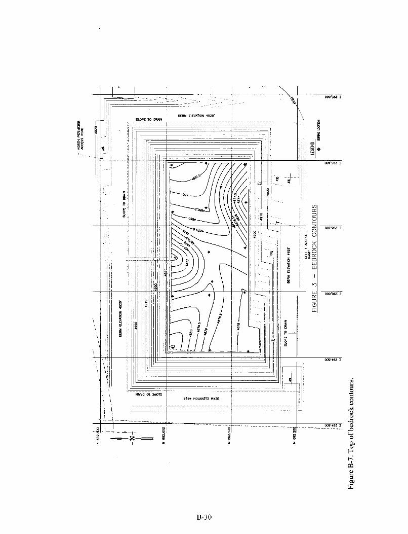
Top of bedrock contours .............................................................................................................. B-30
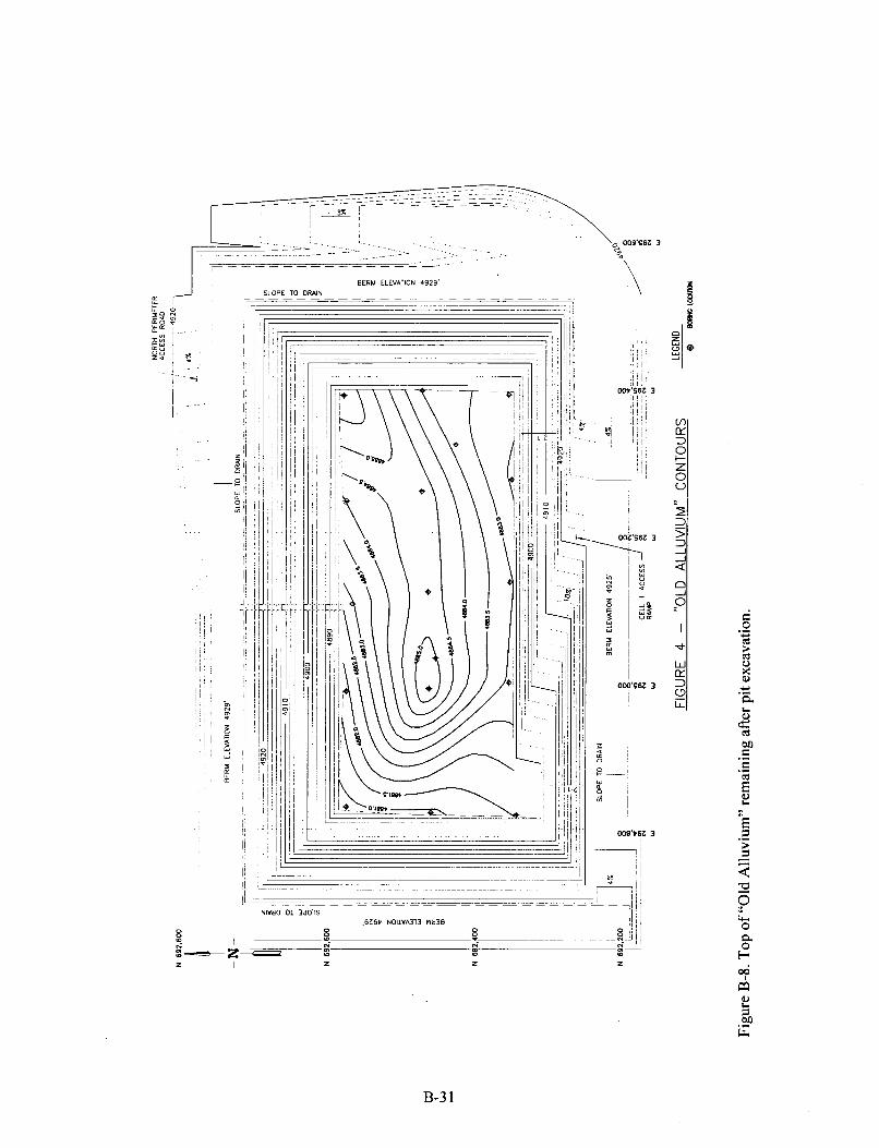
Top of “Old Alluvium” remaining after pit excavation ................................................................ B-31
B.9 . Thickness of fine-grained sediment ............................................................................................. B-32
TABLES
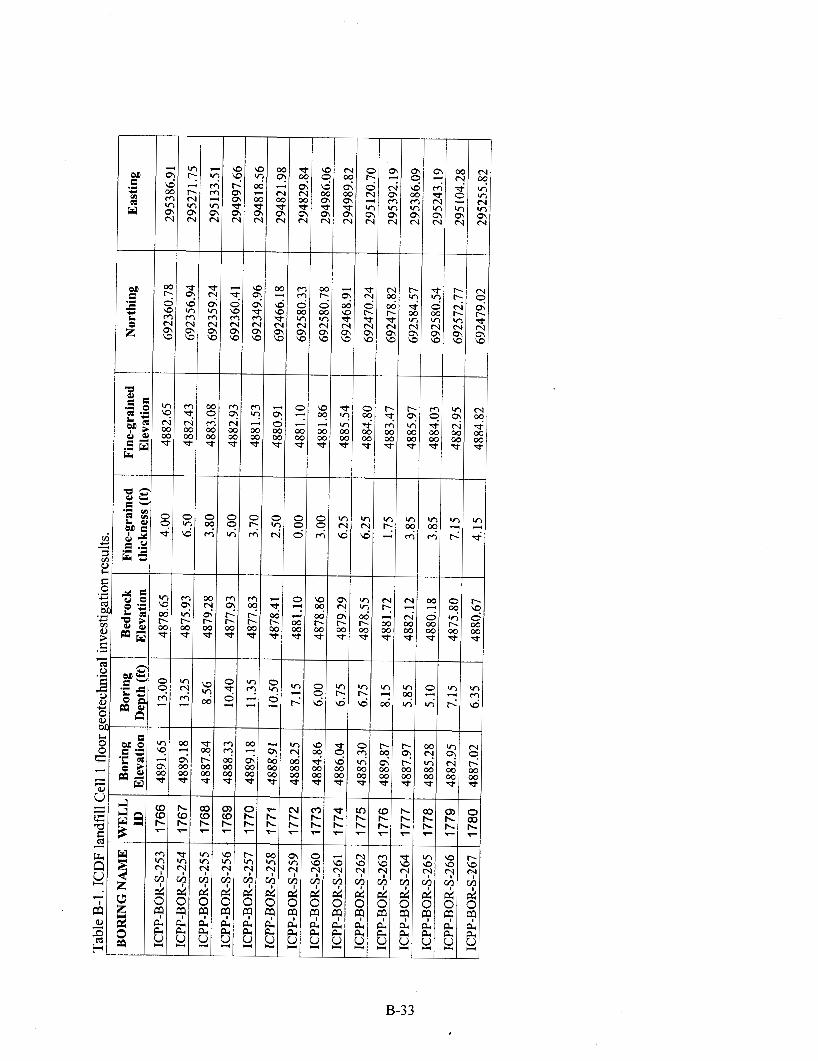
B.1 . ICDF landfill Cell 1 floor geotechnical investigation results ....................................................... B-33
B -3

B-4
B-I. GEOLOGIC DATA
B-1.1 Summary of Results of the ICDF Site Visits to Examine the Sediments in the ICDF Pit
B-I .I .I Objective and Activity Performed
At the request of the ICDF project manager, visits to the ICDF excavation were made between August 29 and October 25,2001, to conduct and record geologic observations during ICDF pit excavation activity. The project requested that a qualified geologist examine the sediments regularly throughout the excavation to confirm previous geotechnical work. The work was also to visually correlate geologic and depositional environments to previous geotechnical borings and establish the geologic framework of the excavated sediments prior to the installation of the landfill liners.
In addition to the field observations, the sediments observed in the excavation were compared to the boring logs of the two original soil borings that were drilled during the initial geotechnical work for placement of the ICDF excavation (see Figures B-1 and B-2). Comparisons between the observed sediments in the excavation and the original soil boring logs are discussed in Section B-1.1.4, Conclusions.
Based on the results of comments and suggestions submitted during internal INEEL Operations Review Board (ORB) document review during January and February 2001, clarifications and revisions to the original draft of this report and the daily site visit reports were made to the original field notes. During the site visit to the ICDF excavation by the agencies on October 16,200 1, copies of the field notes to date were provided to the agency representatives for their information.
The ICDF excavation was visited on nine separate occasions to observe sediments exposed during the ongoing excavation work. Reports of the field observation completed from the visit were prepared and forwarded to ICDF project personnel for their review.
The final site visit associated with the excavation took place on October 25 when the excavation was approximately at the final grade of the pit, and additional excavation was only talung place on the edges of the excavation to remove former access ramps from the pit.
B-I .I .2 Field Evaluation Process
During each of the field visits to examine the exposed sediments in the ICDF pit excavation, approximately % hour was spent in the excavation. The limited period of time available to conduct the field observations was due to safety concerns expressed by the project. The %-hour lunch breaks by the heavy equipment operators was the only available time to safely enter the excavation without interfering with the work in progress. Entrance at this time allowed free access to the excavation without potential conflicts with operating heavy equipment and also lessened potential hazards dealing with heavy equipment operating in the pit while doing the field observations.
While in the pit bottom during each site visit, quick field observations were made of the sediments exposed in the excavation and changes in these sediments since the previous field visit. Field notes on observations and visually observed and measured dips of sedimentary beds were taken. During the last three site visits, digital photographs were also taken of important sedimentary relationships and bedding. Representative copies of these digital photographs are included with this report. The rest of the photographs are on file with the ICDF project.
B-5

I CP P-BOR-S-178( GS B-1) WELL NAME: Easing: 295247.3516(27)Driller: R. Danielson Todays Date 8'14'00
rn1/o0 Facility:
Welt Status inactive
Year Drilled:
Total Depth
~~~~i~~ 692266 .9098(27 )~~~ l~~ i~ t . Cheryl Whitaker Drilling Date
Longitude: Drill Method: Holiwr Stem+ Water Level: n/a
INTEC
well T ~ ~ ~ : Characterization 4.25- IO
2000 Latitude: Drill Fluid: Water Level Date:
44'3. Complelion Depth: - Land S~rlate:492~.~8' Water Lwel Actess:
Dry. 60% line to coarse gravel to 3'. 30% fine Io medlum grained sand, 10% light brownisn gray silts lOYR 6/2 recovery 0.2
Moist, sand 85% grayish brown fine to medium grained sand, 2.5Y 5/2. 10% fine gravel, 5% silt tetter reuwery As above
t
i . .
SP-SM
t Moist. sandy gravel- brown lOYR 93 , 50% rounded lo subangular, line lo coarse (to l'J, 40% fine lo coarse sand. 10% sill. some weak& cemented gravel, recovery 2.2
t Moist, 6W&. coarse g r a d 103'. grayish brown lOYR 52. subrounded gravel,
t Moist. dark grayish brown 10YR4/2.60% coarse to fine (Io T) subrounded to subangular gravel, 30% fine to coarse sand, 10% silt.
Moist brown lOYR 4/3 50% fine to coarse (to 2') subrounded to subangular g r a d basatl pieces. 30% line lo coarse sand, 10% s i l ~
30 14 Maid. 75% line to coarse well graded gravel 10 1 lp, % fine to coarse sand,
lo subrounded sand as above.lOYR 3R -(wet) 5% sin
Moist, 75% fine to coarse subangular lo subrounded gravel 114' to 2'. 20% fine to coarse sand. lOYR 32 -(Wet), 5% silt 0 : ..: . - - . M ~ ~ S I 85% fine to medim some coarse ravel 15% coarse sand, trace silt l O Y d W -(wet). gravel more sorted GPSW
GM Moist. 90% medium to fine sand, some silt, 10% lime basalt gravel, 1/4' to 314'.
ML Mottled gray to cream dayey silt onb a trace day. none to slight piasticity
lOYR 5'2 - (wet)
Top 01 basalt 44'3'
50 t . ~-
i 2o
GP-GM
30
GP-GM
- 40 c CL - Cl
- 50
Figure B-1. Soil boring ICPP-BOR-S-178 (GSB-1).
B-6
ICPP-BOR-S-181 WELL NAME (spT-2) Easting: 2w960.7900(27)~iller: R. Danielson Todays Date 8/2/oo Facility: Northing. 692296.4496(27)~~d~~i~t . Cheryl Whitaker Drilling Date 7/11/00 INTEC
well T ~ ~ ~ : Characterization 4.25' IO Longitude: Drill Method: n0k-w Stem -1 Water Level: n/a
well status inactive
20 8
Year Drilled: 2000 Latitude: Drill Fluid: Water Level Date:
Total Depth 42'3" Completion Depth: - Land Surface:4921.60' Water Level Access:
.. ... Moist, 40% line to coarse gravel to 1 1/4., 60% fine to coarse sand, broken ..a. : : : sw angular to subrmnded. trace silt
. . . . sw Slightly moist. 35% fine to coarse gravel to 3/4'+. m e cobbles
.... 22'
- 5 FEET g 2 Lab Res
Charaslm'a
1 I * * 6 SM little discovery Cuttings only. Moist. 75% silt, 10% fine to coarse gravel to 1 112". 15% fine to coarse sand, very
CI
Dry, 65% sand fine to coarse, 25% gravel line to coarse 1'. angular broken to subrounded 5% silt. Some rook and sticks ... Dry, 70% fine to coarse gravel lo 1 l/C, 30% fine to coarse sand, a few % silt, broken, angular subrounded. gravel cvntains basalt. mudstone. limestone. slhstone. quam
-GW 16' .? :,.. . .. .*
Dry. 55% f i to coarse gravel to 2 ., 45% fine to coarse Sand, a lew % silt, broken angular to subrounded
Slightly moist. 55% fine to coarse gravel lo 2 1R'. 45% line to coarse sand, trace sib. gravel Iradion slightly smaller overall. angular broken to subrounded
'"1 1 ~,. l:-*c:q GW b ' ' 0
GW Asabove
Slightly moist 55% fine to coarse gravel to 2 1/2". 45% line to coarse sand, GW/SW trace silt, brken angular to subrounded. some cobbles
$:.:fa 1 ,o 1 19. 1. ,...',, 1 sw /Gw Moist. W A fine to coarse gravel to 3/4'+, 50% fine to coarse sand. trace silt. smaller size gravel fraction werall
0.'. .. Moist,'% fine to coarse gravels 10 P. 50% fine to coarse sand, m e elongated gravel, trace sit, broken, angular to subrounded
1 71 1 13. bi.gj GW/SW ..
15
Moist some as above, silty sand abrbpt change at - 38: lOYR 4tJ - (wet). 114' rope,
7, 12.13,13. Blows
lOYR 6/3 - (wet), 1/16' rope. medium plasticity
SM slighl'plastlaty
CL Moist, Siny sand wim sandy lenses, sandy day at about 41'1V.
Top of basalt 42'T
50 L -.
sc GW-GM
GP-GM
GP-GM
GP-GM
ML I
SMI
FEEl
0
10
20
30
40
50
Figure B-2. Soil boring ICPP-BOR-S-181 (SPT-2).
B-7
It should be noted that by the time the field observation were requested and begun the upper 3 to 6 ft of sediments had already been removed from the area of the excavation. Therefore, no discussion or observations of these sediments was possible and are not included in this report.
B-I .I .3
The field visits to the ICDF pit observed the excavation of the unconsolidated sediments from depths of approximately 6 ft below the ground surface (bgs) to the final grade of approximately 38 ft bgs. The results of the observations are summarized below by outlining the general composition of the unconsolidated sediments based on the depth of the sediments below the original ground surface.
Approximately 6 to 8 ft bas
Results of Field Visits
The upper 6 to 8 ft of sediments exposed in the excavation consisted of mixed fine to coarse gravels and fine to coarse-grained sand with little or no observed bedding or layering. Small sections of weakly cemented sand lenses approximately 1 ft thick with occasional voids (6 in. to 1 ft in diameter) were observed at erratic, discontinuous intervals within the gravels in the northwest quarter of the excavation.
Approximately 8 to 30 ft bgs:
Most of the western side of the excavation was sand and gravels similar to those observed in the upper 0- to 8-ft section discussed above with only occasional sandy interbeds.
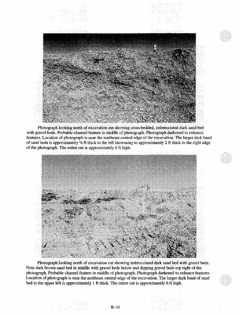
The central portion of the excavation and extending nearly to the eastern edge consisted of interbedded sands and gravels. The sands and gravels occur in alternating 2- to 3-ft layers or beds with crosscutting and imbricated relationships. The beds consist of fine to coarse-grained sands with silt, and fine to coarse gravels with sand layers. The beds are generally more steeply dipping on the eastern side with observed and visually measured dips of 8 to 15 degrees to the west. The beds gradually become flatter or with variable shallow dips in both the easterly and westerly directions extending towards the center of the excavation. Towards the western side, the beds often dip gently to the east at observed and visually measured dips of 3 to 5 degrees to the east. Examples of these beds are shown in the photographs in Figure B-3.
Approximately 30 to 33 ft bgs:
Throughout most of the excavation at this depth thin alternating layers of fine to coarse gravels and fine to coarse-grained sand with minor silts and clays were observed. The sand layers are often moist, especially towards the center of the excavation.
Approximately 33 to 36 ft bgs:
Throughout most of the excavation at this depth, thin, alternating layers of medium to coarse-grained sand with silt and minor (40%) gravel, and pebble-sized pieces of quartz and shale in the sands were observed. The sands are often moist, especially towards the center of the excavation. Examples of this section are shown in the photographs in Figure B-4.
Approximately 36 to 38 ft bgs:
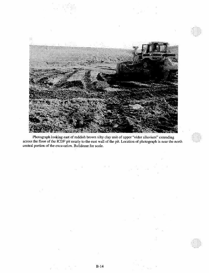
The lowermost unit exposed in the excavation is a reddish-brown silty clay with 4 0 % fine-grained sand. This unit was observed in the bottom of the excavation throughout the north-central portion of the excavation extending nearly to the northwest and northeast comers of the pit. This unit is locally known as the “older alluviumyy and the reddish-brown silt clay observed in the excavation probably represents the uppermost party of the “older alluvium”. Examples of this section are shown in the photographs in Figure B-5.
B-8

s of the sediments observed in the ICD 0% 8 eo 30 ft bgs,
ned to enhance features. Loeation e larger dark bands of sand beds are app
wi fei of of
ast central edge of the exc
13-10

ments observed in the ICDF excavat~on at depth of 33 to
upper part of the cut for sc ~ ~ r o x i ~ a t e l ~ 4 A high.
of ex n& sand Note middle of
cut is a ~ p r o x ~ ~ t e l y 3 to 4 ft
B-1 a

southwest corner across floor of ~ x c a v ~ ~ o n to cut s of the excavation from the fore
oor to the cut consists of the sand 1
B-12
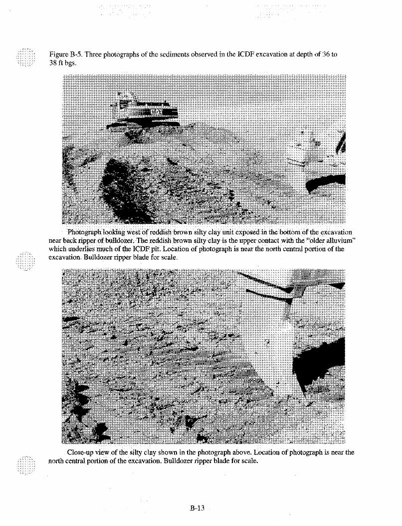
Figure B-5. T 38 ft bgs.
s of the sediments observed in the ICDF excavatio~ at depth of 36 to
- - e for scale,
north central portion of the e ~ c a v a ~ o ~ . ~ u ~ l d o ~ r
-13
Photograph across the floor of central portion of the e~cavation. Bulldozer for scale.
east of reddish brown silty clay unit of upper “older all F; pit nearly to the east wall of the pit. Location of p th
B-14

B-I .I .4 Conclusions
The depositional environments described in the field observations site visit reports are older or “paleo” environments that represent deposition that may be related to much older deposition episodes. These depositional episodes may be related to earlier glaciation-related events in the surrounding mountain ranges. For details of these older glacial periods of depositions, refer to Rathburn (1 991) and Barraclough et al. (1976). Barraclough et al. (1976) describes Pleistocene-aged (10,000 to 2 million years before present [mybp]) glacial deposition in the area of the INEEL fkom large quantities of coarse sands and gravels being released and deposited in a cataclysmic flood from the breakage of a glacial ice dam which had stored water and sediments behind the dam. It is reported this ice dam broke and a large quantity of water carrying coarse sand and gravel was washed out onto and was deposited on the plain below, part of which is now occupied by the INEEL. Such a cataclysmic event could provide the depositional source for the poorly sorted sands and gravels observed in portions of the ICDF excavation. Large quantities of coarse sand and gravels are often washed out from glacial environments and are deposited in the valleys below. This is a plausible explanation of the deposition of much of these sediments. The paleo-stream channels observed and described below could also occur in these environments during later stream erosion and depositional activities.
As stated in the introductory section of this report, part of the overall objective of the site visits during the ICDF excavation activity was to compare the sediments observed in the excavation to sediments logged in original geotechnical soil borings drilled in the area of the ICDF excavation. Two previous soil borings, ICPP-BOR-S-178 (GSB-1) and ICPP-BOR-S-181 (STP-2), were located in the area that was excavated for the ICDF pit (Figure B-6). The boring logs of these two soil borings are included with this report as Figures B-1 and B-2. The boring logs of these two soil borings were compared to the sediments observed in the ICDF excavation in approximately the same locations.
Overall, there is good general correlation between the logged sediments in the bore holes and the sediments observed in the excavation. The overall makeup of the sediments as poorly sorted fine to coarse gravels and fine to coarse sands correlates well between the boring logs and the field observations made of the excavation. The soil boring logs did note more moist sediments in the boreholes than was observed in the excavation. However, the ICDF excavation observations had the advantage of looking at the more lateral extent of the sediments from which the paleo-braided stream channel sediments were observed. This type of observation and correlation would be difficult to make in a single bore hole. In Borehole ICPP-BOR-S-181 (SPT-2), the depth of the uppermost contact with the “older alluvium” of approximately 35 ft bgs was closely matched with the occurrence of the “older alluvium” in the excavation. In Borehole ICPP-BOR-S-178 (GSB-I), the depth of the uppermost contact with the “older alluvium” was logged at 40 ft when the actual contact in the excavation was observed at approximately 36 ft bgs based on the control survey of the bottom of the excavation.
Based on the observations during the site visits during the excavation of the ICDF pit, the following conclusions are submitted.
1. The upper 8 ft of sediments exposed in the excavation show little to no evident bedding or layering of the coarse sands and gravels.
2. The middle 8 to 30 ft exposed in the excavation may represent a paleo-braided stream channel system that deposited sediments throughout area of the center of the excavation. Based on the dips of the sediments, one edge of the braided stream channel was located near the eastern edge of the excavation as shown by the steeper westerly dip near the eastern edge. The eastern edge of this paleo-braided stream channel is located approximately 50 to 80 ft west of the eastern edge of the
B-15

BERM ELEVATION 4929 I SLOPE TO DRAIN
0 7-
Y
s
9s a, !
i
I 000'562 3
s; s I I w w
OOB'f
7 !3
. . z I z z
B-16
bottom of the excavation. This steep dip grades gradually westerly to flatter dips or sediments with variable shallow dips in both the easterly and westerly directions that may represent the braided channels in the stream system. The western edge of this paleo-braided stream system is located approximately 90 to 110 ft east of the western edge of the bottom of the excavation.
3. The section from 30 to 36 ft may represent a moderate energy paleo-depositional system with less coarse gravels and more sand. This section does not show the paleo-braided stream nature of the section above.
4. The final section in the bottom of the excavation from 36 to 38 ft is much finer-grained sand, silt and clay that are locally named the “older alluvium”. The reddish-brown silty clay exposed in the bottom of the pit grades down to the fine silts and clays detected in the boreholes in the bottom of the pit.
B-I .I .5 Follow-up Soil Borings in the Bottom of the ICDF Pit
Following the completion of the excavation of the ICDF pit, the project manager requested that 15 shallow soil borings be drilled in the bottom of the pit. The objective of these borings was to identify and verify the depth of the sediments below the bottom of the pit to the basalt bedrock interface.
During the dnlling of these boreholes, Lexan sample tubes of the sediments being drilled were collected for the entire drilled depth of each soil boring. A registered geologist was on site during the drilling of each soil boring and all of the sediments collected in the Lexan tubes was logged by the geologist using the Unified Soil Classification System and a Munsell color chart.
The results of the soil boring and logging activity are reported in the separate dnlling summary section of this appendix.
B-1.2 Results of Initial Visits to Examine the ICDF Excavation Sediments
B-I .2.1 Visit on August 29,2001
Objective
The objective of this work is for a qualified geologist to regularly examine sediments exposed during excavation of the ICDF Cell #1 to confirm previous geotechnical work. The work was also to visually correlate ‘geologic and depositional environments to previous geotechnical borings and establish the geologic framework of the excavated sediments prior to the installation of the landfill liners.
Detail of Site Visit
The initial visit to the ICDF #1 Cell excavation took place on Wednesday, August 29,2001. Approximately 2 hours were spent at the ICDF site with approximately 1 hour of that time spent in the excavation loolung at the subsurface sediments currently exposed in the walls of the excavation.
B-17

Results
1.
2.
3.
4.
5 .
6.
7.
8.
9.
The following observations were made during this initial visit to the ICDF excavation:
The current excavation at the time of the visit ranged in depth from approximately 3 ft deep in the southwest comer to approximately 6 ft deep in the current northeast portion of the excavation. The deepest part being the area below worked on by the excavators during the site visit.
Along the north wall of the excavation, in the northwest comer observed during this visit, the upper most sediments consist of an approximately 2-ft-thick section of surface sediments made up of thinly bedded to graded silt, sand and fine gravel.
Below the surface sediments are approximately 3 to 4 ft of fine to coarse gravel (pebble to cobble size) mixed with fine to coarse-grained sand.
The gravel is composed is from 80% to 90% basalt fragments with the other lo+% being mostly quartz material.
There is little to no obvious bedding within most of the lower gravel unit.
In a small exposure in the north wall of the excavation, and also to the south of the north wall near the current excavation activity, a 1 -ft-thick bedded, moderately cemented, moderately sorted sand with fine gravel bed is visible approximately 3 to 4 ft below the surface. This cemented, bedded sand unit has an observed and visually measured dip to the south at 8 to 10 degrees.
Below the cemented sand with gravel bed, there appears to be a void in the gravel and sand. The void is less than 1 ft below the bed.
Below the areas where the cemented sand with gravel bed was observed, there is approximately 2 ft of poorly sorted mixed fine to coarse gravel and sand.
The general impression when walking throughout the current excavation was that the gravels were becoming finer (smaller in overall size of individual gravel) toward the southern portion of the current excavation.
Summary of Field Observation
Based on the results of this initial visit, other than the single isolated void or hole observed below the cemented sand with gravel bed, there were no areas of unusual or anomalous geologic and sedimentary features observed in the excavation.
Submitted August 3 1,200 1
B-I .2.2 Visit on September 13, 2001
0 bject ive
The objective of this work is for a qualified geologist to regularly examine sediments exposed during excavation of the ICDF Cell #1 to confirm previous geotechnical work. The work was also to
B-18
visually correlate geologic and depositional environments to previous geotechnical borings and establish the geologic framework of the excavated sediments prior to the installation of the landfill liners.
Detail of Site Visit
The second visit to the ICDF #1 Cell excavation took place on Thursday, September 13,2001. Approximately 2 hours were spent at the ICDF site with approximately 45 minutes of that time spent down in the excavation looking at the subsurface sediments currently exposed in the walls of the excavation. Since the level of equipment activity in the excavation has increased significantly since the previous visit, the only time spent in the excavation was during the lunch break by the crew.
Results
The following observations were made during this visit to the ICDF excavation:
1.
2.
3.
4.
5 .
6 .
The current excavation at the time of the visit ranged in depth from an estimated 8 to 9 ft deep in the southwest comer to estimated 12 ft deep in the current northeast portion of the excavation. Three excavators were working in various parts of the excavation at the time of the visit.
In the northwest comer of the excavation, 1 - to 2-ft thick isolated sections of a weakly to moderately cemented, moderately sorted sand with fine gravel bed are still visible. This cemented layer was originally observed during the site visit on August 29, 2001.
Moving from the northwest to the southwest comer of the excavation the gravel become finer (smaller) and the gravel is roughly bedded with a 2 to 3 degree southerly observed and visually measured dip.
Along the south wall of the excavation at a depth of approximately 5 to 6 ft bgs is a fairly continuous 2- to 3-ft thick interbedded, weakly cemented fine to coarse-grained sand with silt and fine gravel.
In the central (middle) portion of the excavation at an estimated depth of 10 to 12 ft bgs a nearly continuous sandykilty layer with less gravel (20 to 30%?) is exposed with rough bedding at 8 to 12 degrees observed and visually measured dip to the west.
Based on the observations made during this visit, the sandsilt bed exposed in the middle of the excavation dips to the west and then becomes flatter near the western edge of the excavation. There is also less gravel observed in the sandy/silty beds and the gravel that is present is well rounded and fine to coarse.
Summary of Field Observation
Based on the results of this second site visit, other than the cemented sand with gravel bed that was noted during the August 29, 200 1, visit and observed again during this visit in the northwest comer of the excavation, there were no areas of unusual or anomalous geologic and sedimentary features observed in the excavation.
Submitted September 18,2001
B-19
B-I .2.3 Visit on September 20,2001
Objective
The objective of this work is for a qualified geologist to regularly examine sediments exposed during excavation of the ICDF Cell #1 to confirm previous geotechnical work. The work was also to visually correlate geologic and depositional environments to previous geotechnical borings and establish the geologic framework of the excavated sediments prior to the installation of the landfill liners.
Detail of Site Visit
The third visit to the ICDF #1 Cell excavation took place on Thursday, September 20, 2001. Approximately 2 hours were spent at the ICDF site with approximately 30 minutes of that time spent down in the excavation looking at the subsurface sediments currently exposed in the walls of the excavation. Since the level of equipment activity in the excavation remains high, the only time spent in the excavation was during the lunch break by the excavation crew.
Results
The following observations were made during this visit to the ICDF excavation:
1.
2.
3.
4.
5.
The current excavation at the time of the visit ranged in depth from an estimated 12 ft deep in the north-central portion of the excavation to estimated 15 ft deep in the northwest and central portions of the excavation. Three excavators were working in various parts of the excavation at the time of the visit.
In the northwest comer of the excavation, several 1- to 2-ft thick isolated sections of weakly cemented, moderately sorted sand with fme gravel bed are still visible. The upper beds and pockets consist of coarse to medium-grained sand with 30% to 40% fine to coarse, well rounded to sub- angular gravel to 6-in. size with observed and visually measured dip of 2 degrees to the west. Beds below are 60% to 70% fine to coarse gravel with fine top medium-grained sand. The cemented layer was originally observed during the site visit on August 29,2001.
In the north-central portion of the excavation at 12 to 13 ft bgs, the excavation is also starting to get into a sandy, coarse gravel similar seen in the lower beds noted in #2 above and also gravel was observed in the central portion of the excavation during the September 13th visit. Some larger cobble-sized gravel observed here but not in location #2 above. There was an observed and visually measured dip to the upper gravels of 3 degrees to the west.
In the central portion of the excavation at an approximate depth of 15 fi bgs the excavation exposes a fine angular to sub-angular gravel with interbedded fme sand with silt layers. This unit would be located below the gravelly sand unit observed throughout much of the south and central part of the excavation during the September 1 3th visit to the excavation. Observed and visually measured dip in these gravel with sandsilt interbeds is approximately 3 degrees to the east in the western part to 6 to 8 degrees to the west in the eastern part but the beds appear to have variable dips with some cross bedding of gravels overlying sand units.
It appears that the beds exposed in the excavation are gravels and sands of a possible paleo-braided stream channel origin with variable amounts of gravel and sand content with variable size gravels with variable degrees of rounding.
B-20

6. During this visit it appeared that the gravelhand beds exposed in the middle of the excavation dip to the west and then become flatter to slightly eastward dipping near the western edge of the excavation. The beds appear to dip more steeply in the eastern portion of the excavation than in the western portion.
Summary of Field Observation
Based on the results of this visit, other than the cemented sand with gravel bed that was noted during the August 29,2001, visit and observed again during this visit in the northwest comer of the excavation, there were no areas of unusual or anomalous geologic and sedimentary features observed in the excavation.
Submitted September 27,2001
B-1.2.4 Visit on September 27,2001
Objective
The objective of this work is'for a qualified geologist to regularly examine sediments exposed during excavation of the ICDF Cell #1 to confirm previous geotechnical work. The work was also to visually correlate geologic and depositional environments to previous geotechnical borings and establish the geologic framework of the excavated sediments prior to the installation of the landfill liners.
Detail of Site Visit
The fourth visit to the ICDF #1 Cell excavation took place on Thursday, September 27,2001. Approximately 2 hours were spent at the ICDF site with approximately 30 minutes of that time spent down in the excavation looking at the subsurface sediments currently exposed in the walls of the excavation. Since the level of equipment activity in the excavation continues to be high, the only time spent in the excavation was during the lunch break by the excavation crew.
Results
The following observations were made during this visit to the ICDF excavation:
1.
2.
3.
The current excavation at the time of this visit ranged in depth from an estimated 15 ft deep in the north-central portion of the excavation to an estimated 18 ft deep in the northwest portions of the excavation. Three excavators were working in various parts of the excavation at the time of this visit.
The south wall of the excavation now exhibits sandy gravel beds with minor clay in the sand unit. This unit extends to the southwest comer of the excavation where it becomes a 3-ft-thick sandy lense with gravel with rough bedding at an observed and visually measured dip of 6 degrees to the north.
In the eastern portion of the south wall of the excavation, there is a sandy gravel exposed with more rounded gravel (to cobble size) with fine to coarse-grained sand. There is more gravel and less sand then observed during previous visits to this portion of the excavation. The current observed unit would be below the gravelly sand unit described in the September 13'h visit report.
B-21

4. In the east central portion of the excavation at an approximate depth of 15 to 16 ft bgs, the excavation exposes sandy gravel beds with an observed and visually measured dip to the west of 5 to 15 degrees.
5. In the west central portion of the excavation at a depth of approximately 18 ft bgs, alternating layers of fine gravel with fine to coarse sand were observed. The alternating layers are from 6 in. to 1 ft thick and have an observed and visually measured dip to the west of 3 degrees.
6. In a newly exposed area of the excavation in the northwest comer near the north wall, the exposure appears sandier with fine to coarse, well-rounded gravels. This unit appears different from the sandy gravel units above since there is more fine gravel and a higher degree of rounding to the gravel. This may be the first exposure of a different, lower, more finely grained section. This area will be examined further and this unit will be looked for in other parts of the excavation during the next visit to the excavation next week.
Summary of Field Observation
Based on the results of this visit there were no areas of unusual or anomalous geologic and sedimentary features observed in the excavation.
Submitted September 27,2001
B-I .2.5 Visit on October 5,2001
Objective
The objective of this work is for a qualified geologist to regularly examine sediments exposed during excavation of the ICDF Cell #1 to confirm previous geotechnical work. The work was also to visually correlate geologic and depositional environments to previous geotechnical borings and establish the geologic framework of the excavated sediments prior to the installation of the landfill liners.
Detail of Site Visit
The fifth visit to the ICDF #I Cell excavation took place on Thursday, October 4,2001. Approximately 2 hours were spent at the ICDF site with approximately 30 minutes of that time spent down in the excavation looking at the subsurface sediments currently exposed in the walls of the excavation. Since the level of equipment activity in the excavation continues to be high, the only time spent in the excavation was during the lunch break by the excavation crew.
Results
The following observations were made during this visit to the ICDF excavation:
1. According to discussions with the on-site staff, the current excavation at the time of this visit ranged in depth from an estimated 20 ft deep in the northeast portion of the excavation to an estimated 25 ft deep in the southem half of the excavation. Three excavators were workmg in various parts of the excavation at the time of this visit.
B-22
2.
3.
4.
5.
6.
7.
The crew is also currently using material removed from the excavation to build up the berms around the excavation. At the time of this visit, the berm is approximately 3 ft above the normal ground surface
The excavation is currently working on removing material in the south central portion of the excavation. The majority of the gravels and sands exposed for examination during this visit are exposed around this south central portion of the excavation.
The overall material exposed in this south central cut is coarse gravels with 1-ft-thick beds of medium to coarse sand alternating with thinner (6 in. thick) beds of fine gravel with sand to sand.
In the southwest corner of the south central cut is exposed are several 1-ft-thick beds of fine to coarse-grained sand in cross-cutting relationships with general overall observed and visually measured dip of 5 degrees to the east.
On the north side of the central cut is exposed a series of beds dipping at various angles across the face of the cut in an east to west direction for approximately 300 ft, the following sequence was observed:
a. At the eastern end of the cut are sandy gravel beds dipping westward at an observed and visually measured dips of 4 to 5 degrees and then increases to 6 degrees.
b. Further east, the observed and visually measured dip of the sandy gravel beds increases to approximately 10 degrees to the east and then gradually flattens.
c. In the middle portion of the cut are thin (6 in. thick) flat-laying beds of fine, well-rounded gravel with coarse-grained sand.
d. In the eastern end of the cut are 6 in.-to-1-ft thick beds of coarse gravels with medium to coarse-grained sand.
The above-described section appears to be a cross-section across a shallow paleo-channel or series of paleo-channels from previous older streadriver deposition that may be similar to a braided stream channel sequence.
Summary of Field Observation
Based on the results of this visit, other than noted in the descriptions above, there were no areas of unusual or anomalous geologic and sedimentary features observed in the excavation.
Submitted October 1 1,2001
B-I .2.6 Visit on October I O , 2001
Objective
The objective of this work is for a qualified geologist to regularly examine sediments exposed during excavation of the ICDF Cell #1 to confirm previous geotechnical work. The work was also to visually correlate geologic and depositional environments to previous geotechnical borings and establish the geologic framework of the excavated sediments prior to the installation of the landfill liners.
B-23
Detail of Site Visit
The sixth visit to the ICDF #1 Cell excavation took place on Wednesday, October 10,2001. Approximately 2 hours were spent at the ICDF site with approximately 30 minutes of that time spent down in the excavation looking at the subsurface sediments currently exposed in the walls of the excavation. Since the level of equipment activity in the excavation continues to be high, the only time spent in the excavation was during the lunch break by the excavation crew.
Resu Its
The following observations were made during this visit to the ICDF excavation:
1.
2.
3.
4.
5.
The current excavation at the time of this visit was estimated to range in depth below the normal ground surface from an estimated 25 ft deep in the northwest portion of the excavation to an estimated 28 ft deep in the southeastern and northeastern portions of the excavation where the active excavation was currently takmg place. Two excavators and one bulldozer plus associated trucks were working in various parts of the excavation at the time of this visit.
The crew continues to remove material from the excavation to build up the berms around the excavation. At the time of this visit, the berm on the north side is approximately 2 to 3 ft above the normal ground surface while the berm on the southwest side is approximately 4 ft above the normal ground surface.
The excavation is currently working on removing material in the northeast, east central, and southeast portions of the excavation. The majority of the gravels and sands exposed for examination during this visit are exposed in the cuts in this material.
The overall material exposed in the cuts are alternating sequences of coarse gravels with 1- to 3-ft-thick beds of medium to coarse sand alternating with thinner (6 in. thick) beds of fine gravel with sand to sand with gravel beds.
In the southeast excavation cuts are exposed a series of alternating beds that may represent a filled, cross cutting paleo-channel with interbedded sands and gravels. The sequence along the cut going from east to west over a distance of approximately 300 to 400 ft is as follows:
a. At the eastern end of the cut are coarse-grained unconsolidated sand beds that appear to be filling a paleo-channel. The sand bed is overlain and underlain by cross cutting interbedded units of fine to coarse gravel and fine to coarse-grained sand lenses. The eastern limb of this channel has an observed and visually measured dip to the west of 15 degrees.
b. Further to the east by approximately 100 ft are thin (6 in.) to thick (3 ft) beds of coarse to fine gravels with interbedded sand lenses 6 in. to 2 ft thick. Observed and visually measured dips vary across this 20-ft-long cut fi-om 10 degrees to the west on the eastern end to 16 degrees to the east on the western end.
c. Approximately 50 to 100 ft to the west, the observed and visually measured dip decreases to 4 degrees to the east.
d. At the western end of the cut are exposed thin (6 in. to 1 ft) beds of fine gravel mixed with alternating 1- to 2-ft-thick beds of beds of coarse gravel with sand. Beds are level to gently westward dipping at an observed and visually measured angle of 4 degrees.
B-24

6. At the very bottom of the current cuts at depths of approximately 28 ft below the normal ground surface, there appear to be an increased amount of sand with some clay being excavated. This will be checked during the next site visit next week.
Summary of Field Observation
Based on the results of this visit, other than the geologic observations noted in the discussions above, there were no areas of unusual or anomalous geologic and sedimentary features observed in the excavation .
Submitted October 1 1,200 I
B-I .2.7 Visit on October 18,2001
Objective
The objective of this work is for a qualified geologist to regularly examine sediments exposed during excavation of the ICDF Cell #I to confirm previous geotechnical work. The work was also to visually correlate geologic and depositional environments to previous geotechnical borings and establish the geologic framework of the excavated sediments prior to the installation of the landfill liners.
Detail of Site Visit
The seventh visit to the ICDF #1 Cell excavation tookplace on Thursday, October 18,2001. Approximately 2 hours were spent at the ICDF site with approximately 30 minutes of that time spent down in the excavation looking at the subsurface sediments currently exposed in the walls of the excavation. Since the level of equipment activity in the excavation continues to be high, the only time spent in the excavation was during the lunch break by the excavation crew. Digital photographs were taken during this site visit.
Results
The following observations were made during this visit to the ICDF excavation:
1.
2.
3.
4.
The current excavation at the time of this visit was estimated to range in depth below the normal ground surface fi-om an estimated 28-30 ft deep. Three excavators and one bulldozer plus associated trucks were working in various parts of the excavation at the time of this visit.
The crew continues to remove material from the excavation to build up the berms around the excavation. At the time of this visit, the berm on the northeast corner is approximately 5-6 ft above the normal ground surface while the berm on the northwest corner is approximately 4-5 ft above the normal ground surface.
The active excavation was currently taking place in the northeast corner, the north central and western sections of the excavation. The majority of the gravels and sands exposed for examination during this visit are exposed in the cuts in these areas.
In the north central part of the excavation cuts are exposed a series of thin (6-in.-thick) alternating beds of fine to coarse gravels with fine to coarse-grained sand with minor silts and clays. The beds have an observed and visually measured dip of 6 degrees to the north.
B-25
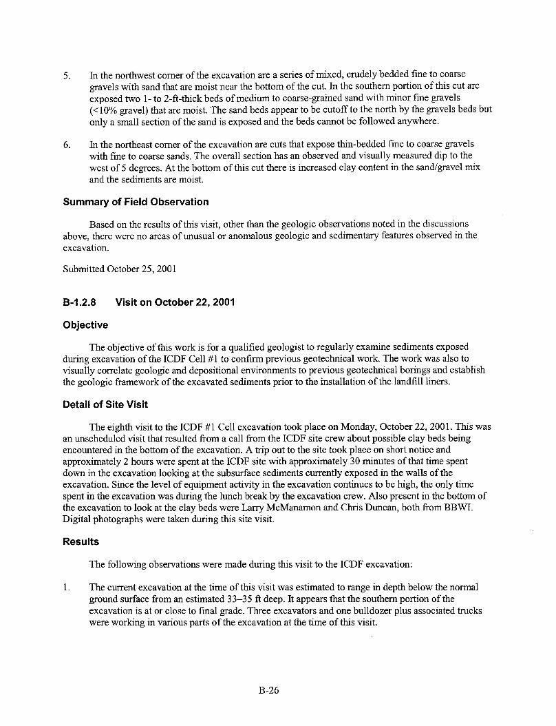
5. In the northwest corner of the excavation are a series of mixed, crudely bedded fine to coarse gravels with sand that are moist near the bottom of the cut. In the southern portion of this cut are exposed two 1 - to 2-ft-thick beds of medium to coarse-grained sand with minor fine gravels ( 4 0 % gravel) that are moist. The sand beds appear to be cutoff to the north by the gravels beds but only a small section of the sand is exposed and the beds cannot be followed anywhere.
6. In the northeast corner of the excavation are cuts that expose thin-bedded fine to coarse gravels with fine to coarse sands. The overall section has an observed and visually measured dip to the west of 5 degrees. At the bottom of this cut there is increased clay content in the sand/gravel mix and the sediments are moist.
Summary of Field Observation
Based on the results of this visit, other than the geologic observations noted in the discussions above, there were no areas of unusual or anomalous geologic and sedimentary features observed in the excavation.
Submitted October 25,200 1
B-I .2.8 Visit on October 22,2001
0 bjective
The objective of this work is for a qualified geologist to regularly examine sediments exposed during excavation of the ICDF Cell #1 to confirm previous geotechnical work. The work was also to visually correlate geologic and depositional environments to previous geotechnical borings and establish the geologic framework of the excavated sediments prior to the installation of the landfill liners.
Detail of Site Visit
The eighth visit to the ICDF #1 Cell excavation took place on Monday, October 22,2001. This was an unscheduled visit that resulted from a call from the ICDF site crew about possible clay beds being encountered in the bottom of the excavation. A trip out to the site took place on short notice and approximately 2 hours were spent at the ICDF site with approximately 30 minutes of that time spent down in the excavation looking at the subsurface sediments currently exposed in the walls of the excavation. Since the level of equipment activity in the excavation continues to be high, the only time spent in the excavation was during the lunch break by the excavation crew. Also present in the bottom of the excavation to look at the clay beds were Larry McManamon and Chris Duncan, both from BBWI. Digital photographs were taken during this site visit.
Resu I ts
The following observations were made during this visit to the ICDF excavation:
1. The current excavation at the time of this visit was estimated to range in depth below the normal ground surface from an estimated 33-35 ft deep. It appears that the southern portion of the excavation is at or close to final grade. Three excavators and one bulldozer plus associated trucks were working in various parts of the excavation at the time of this visit.
B-26

2.
3.
4.
5.
6.
The crew continues to remove material from the excavation to build up the berms around the excavation or the excavated material is being hauled to the soil storage pile south of the ICDF excavation.
The active excavation was currently takmg place in the northeast comer, the north central and western sections of the excavation. The majority of the gravels, sands, silt and clays exposed for examination during this visit are exposed in the cuts in these areas.
In the north central part of the excavation exposed in the bottom of the cut are exposures of reddish-brown silty clay. The silty clay has minor ( 4 0 % ) fine-grained sand and the material exposed is dry to moist.
In the northeast comer of the excavation addition exposures of the silty clay observed in #4 above were also observed. In this area, the silty clays appear to be overlain by a medium to coarse-grained sand that contains approximately 10-15% small pebble-sized pieces of quartz and shale. This sequence of silty clay and overlying sand beds were observed in three locations in this northeast comer.
In the northcentral portion of the excavation is a 2-ft-high cut that exposes medium to coarse- grained sands that are well-sorted with very little (<5%) fine gravel. This appears to be a very clean sand and is moist at the bottom of the cut.
Summary of Field Observation
The well sorted sand beds and the silty clay beds observed during this site visit may represent the uppermost part of what is called the “older alluvium”. This “older alluvium” is commonly located immediately above the bedrock basalts in the area of the ICDF.
Based on the results of this visit, other than noted in the discussions above. there were no areas of unusual or anomalous geologic and sedimentary features observed in the excavation.
Submitted October 25,2001
B-I .2.9 Visit on October 25,2001
Objective
The objective of this work is for a qualified geologist to regularly examine sediments exposed during excavation of the ICDF Cell #1 to confirm previous geotechnical work. The work was also to visually correlate geologic and depositional environments to previous geotechnical borings and establish the geologic framework of the excavated sediments prior to the installation of the landfill liners.
Detail of Site Visit
The ninth visit to the ICDF #1 Cell excavation took place on Thursday, October 25,2001. Approximately 2 hours was spent at the ICDF site with approximately 30 minutes of that time spent down in the excavation looking at the subsurface sediments currently exposed in the walls of the excavation. The level of equipment activity in the excavation continues to be high, the only time spent in the excavation was during the lunch break by the excavation crew. Digital photographs were taken during this site visit.
B-27
Results
The following observations were made during this visit to the ICDF excavation:
1 .
2.
3.
4.
5 .
6.
7.
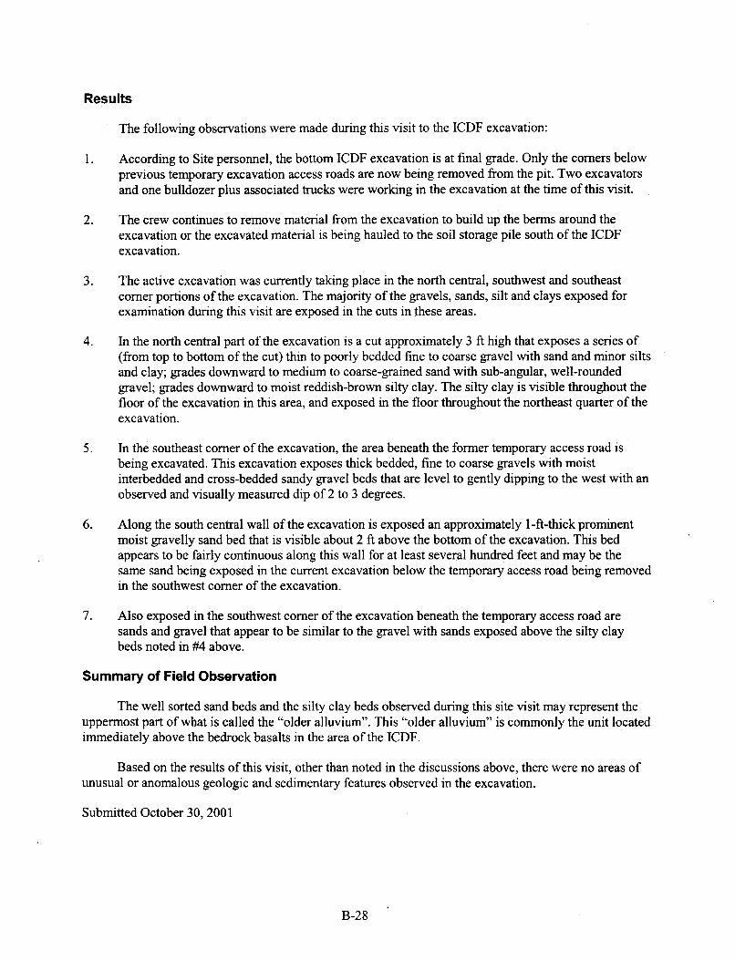
According to Site personnel, the bottom ICDF excavation is at final grade. Only the corners below previous temporary excavation access roads are now being removed from the pit. Two excavators and one bulldozer plus associated trucks were working in the excavation at the time of this visit.
The crew continues to remove material from the excavation to build up the berms around the excavation or the excavated material is being hauled to the soil storage pile south of the ICDF excavation.
The active excavation was currently talung place in the north central, southwest and southeast comer portions of the excavation. The majority of the gravels, sands, silt and clays exposed for examination during this visit are exposed in the cuts in these areas.
In the north central part of the excavation is a cut approximately 3 ft high that exposes a series of (from top to bottom of the cut) thin to poorly bedded fine to coarse gravel with sand and minor silts and clay; grades downward to medium to coarse-grained sand with sub-angular, well-rounded gravel; grades downward to moist reddish-brown silty clay. The silty clay is visible throughout the floor of the excavation in this area, and exposed in the floor throughout the northeast quarter of the excavation.
In the southeast comer of the excavation, the area beneath the former temporary access road is being excavated. This excavation exposes thick bedded, fine to coarse gravels with moist interbedded and cross-bedded sandy gravel beds that are level to gently dipping to the west with an observed and visually measured dip of 2 to 3 degrees.
Along the south central wall of the excavation is exposed an approximately l-fi-thick prominent moist gravelly sand bed that is visible about 2 ft above the bottom of the excavation. This bed appears to be fairly continuous along this wall for at least several hundred feet and may be the same sand being exposed in the current excavation below the temporary access road being removed in the southwest comer of the excavation.
Also exposed in the southwest comer of the excavation beneath the temporary access road are sands and gravel that appear to be similar to the gravel with sands exposed above the silty clay beds noted in ##4 above.
Summary of Field Observation
The well sorted sand beds and the silty clay beds observed during this site visit may represent the uppermost part of what is called the “older alluvium”. This “older alluvium” is commonly the unit located immediately above the bedrock basalts in the area of the ICDF.
Based on the results of this visit, other than noted in the discussions above, there were no areas of unusual or anomalous geologic and sedimentary features observed in the excavation.
Submitted October 30,2001
B-28

B-2. GEOTECHNICAL DATA
B-2.1 Summary of the ICDF Pit Grade to Bedrock Interface Boreholes By Gregory W. Studley, PG
INEEL Environmental Restoration November 26,2001
B-2.1 . I Introduction
This supplemental report summarizes the auger-boring activities started and completed between November 12 to 15,2001, at the INEEL CERCLA Disposal Facility (ICDF) project. For additional definition of the bedrock interface, sub-pit floor lithology, and correlation with previously applied geotechnical and geophysical investigations, 15 auger borings were completed to the bedrock interface. The borings were more or less evenly distributed across the pit floor (Figure B-6).
B-2.1.2 Work Performed
Fifteen auger-bore holes were completed the week ofNovember 12,2001, with 126.26 ft total footage drilled. Data were acquired with an Acker auger-rig equipped with 6.5 in. OD, 4.25 in. ID auger flights, utilizing 2.5-ft sample runs with sample integnty maintained by being collected in 2 . 5 4 LexanTM tubes. The sample tubes were capped, tapped, logged, and documented by an on-site registered geologist throughout the drilling program. The resulting sample tubes are stored in a cargo storage facility at INTEC until disposition is determined. Upon refusal at the bedrock interface, all boreholes were completed by back-filling with bentonite hole plug. The bentonite hole plug was hydrated as back-filling took place, producing a nonreactive impermeable natural product borehole seal.
Samples of the subsurface lithology were described and documented in logbook number ER-35-00 Environmental Restoration Sample & Core Description Logbook. Below is a summary of the recorded field logs advancing major divisions of the Unified Soil Classification System and MunsellB Color chart. Copies of the actual filed boring logs are attached. A copy of the Unified Soil Classification System designations utilized is also attached as part of Section B-2.3. Figures B-6, B-7, B-8, and B-9 and Table B-1 present boring locations, geotechnical results, bedrock contours, “old alluvium” contours, and thickness of “old alluvium” remaining in the pit after excavation..
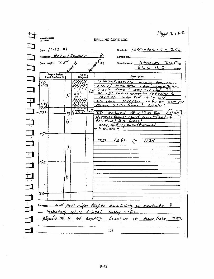
ICPP-BOR-S-253 (ID#l766) DRILLED: I 1-1 3-01
Southeast comer and first auger bore hole in series along south wall of the ICDF pit.
0-2.5 ft
2.5-5.0
5.0-7.5
7.5-10
10-12.5
12.5-13
13.0 ft
GM-predominantly silty gravels, gravel-sand mix, dry-slightly moist, probably disturbedconstruction material. Fining near bottom andor increase in fine sandsilt content
SM-silty sand, slightly moist, gravel near bottom
SM with gravel- sand and silt with gravel up to 20mm, slightly moist; moderate pale brown color- consistent throughout sample run (1 0 yr 5/4)
Poor recovery; fine sand, silt, clay mix with gravel of diverse sizes, moist to very moist
SWSC-very fine sand, silt, clay; moist- forms nice ribbon- very pale orange (10 yr 8/2); ashy appearance? Caliche?
SC-refusal at bedrock. interface -basalt chips, wet; clay, silt, sand mix with basalt gravel/rubble. Fines are very light color(l0 yr 8/2); T.D. 13.0 ft
Total Depth
B-29
002'562 3
OWS6Z 3
N ID
z
B-30
00936Z 3 % ', \
X Z 3 Y .- P,
M c
B-3 1

009'562 3
\ z
I
1 1
m N Ol
I a Y
a;; a
B-32
M e
w .I c,
;
M E
L 3 i?
W
W '?
I
-t
U 0
h K d U h
-
I I I I I I
T -T- I
B-33
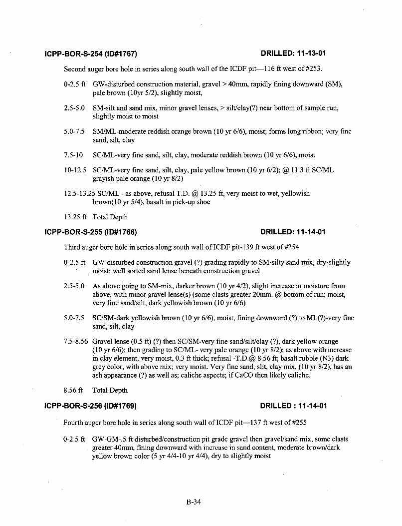
ICPP-BOR-S-254 (I D#l767) DRILLED: 11 -13-01
Second auger bore hole in series along south wall of the ICDF pit-1 16 ft west of #253.
0-2.5 ft GW-disturbed construction material, gravel > 40mm, rapidly fining downward (SM), pale brown (1Oyr 5/2), slightly moist,
2.5-5.0 SM-silt and sand mix, minor gravel lenses, > silt/clay(?) near bottom of sample run, slightly moist to moist
SM/ML-moderate reddish orange brown (10 yr 6/6), moist; forms long ribbon; very fine sand, silt, clay
5.0-7.5
7.5-10 SC/ML-very fine sand, silt, clay, moderate reddish brown (10 yr 6/6), moist
10-12.5 SC/ML-very fine sand, silt, clay, pale yellow brown (10 yr 6/2); @? 11.3 ft SC/ML grayish pale orange (1 0 yr 8/2)
12.5-13.25 SCML - as above, refusal T.D. @ 13.25 ft, very moist to wet, yellowish brown(l0 yr 5/4), basalt in pick-up shoe
13.25 ft Total Depth
ICPP-BOR-S-255 (ID#l768) DRILLED: 11-14-01
Third auger bore hole in series along south wall of ICDF pit-139 ft west of #254
0-2.5 ft GW-disturbed construction gravel (?) grading rapidly to SM-silty sand mix, dry-slightly . moist; well sorted sand lense beneath construction gravel
2.5-5.0 As above going to SM-mix, darker brown (10 yr 4/2), slight increase in moisture from above, with minor gravel lense(s) (some clasts greater 20mm. @? bottom of run; moist, very fine sandhilt, dark yellowish brown (10 yr 6/6)
5.0-7.5 SC/SM-dark yellowish brown (10 yr 6/6), moist, fining downward (?) to ML(?)-very fine sand, silt, clay
7.5-8.56 Gravel lense (0.5 ft) (?) then SC/SM-very fine sand/silt/clay (?), dark yellow orange (1 0 yr 6/6); then grading to SC/ML- very pale orange (10 yr 8/2); as above with increase in clay element, very moist, 0.3 ft thick; refusal -T.D.@ 8.56 ft; basalt rubble (N3) dark grey color, with above mix; very moist. Very fine sand, slit, clay mix, (10 yr 8/2), has an ash appearance (?) as well as; caliche aspects; if CaCO then likely caliche.
8.56 ft Total Depth
IC P P-BO R-S-256 (I D#l769) DRILLED : 11 -14-01
Fourth auger bore hole in series along south wall of ICDF pit-137 ft west of #255
0-2.5 ft GW-GM-.5 ft disturbedkonstruction pit grade gravel then gravelhand mix, some clasts greater 40mm, fining downward with increase in sand content, moderate browddark yellow brown color ( 5 yr 4/4-10 yr 4/4), dry to slightly moist
B-34
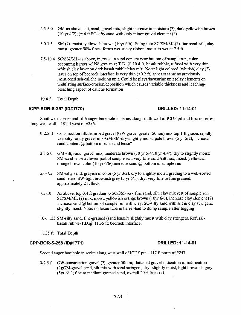
2.5-5.0 GM-as above, silt, sand, gravel mix, slight increase in moisture (?), dark yellowish brown (10 yr 4/2); @ 4 ft SC-silty sand with only minor gravel element (?)
5.0-7.5 SM (?)- moist, yellowish brown (1Oyr 6/6), fining into SC/SM/ML(?)-fine sand, silt, clay, moist, greater 50% fines; forms wet sticky ribbon, moist to wet at 7.5 ft
7.5-10.4 SC/SM/ML-as above, increase in sand content near bottom of sample run, color becoming lighter w/ N8 grey mix; T.D. @ 10.4 ft, basalt rubble, refusal with very thin whitish clay layer on dark basalt rubble/clay mix. Note: light colored (whitish) clay (?) layer on top of bedrock interface is very thin (c0.2 ft) appears same as previously mentioned asldcaliche loohng unit. Could be playa/lacustrine unit (clay element) on undulating surface-erosioddeposition which causes variable thickness and leaching- bleaching aspect of caliche formation
10.4 ft Total Depth
ICPP-BOR-S-257 (ID#l770) DRILLED: 11-14-01
Southwest comer and fifth auger bore hole in series along south wall of ICDF pit and first in series along west wall-1 8 1 ft west of #256.
0-2.5 ft Construction fill/disturbed gravel (GW gravel greater 50mm) mix top 1 ft grades rapidly to a silty sandy gravel mix-GM/SM-dry-slightly moist, pale brown ( 5 yr 5/2), increase sand content @ bottom of run, sand lense?
2.5-5.0 GM-silt, sand, gravel mix, moderate brown (10 yr 5/4/10 yr 4/44, dry to slightly moist; SM-sand lense at lower part of sample run, very fine sand /silt mix, moist, yellowish orange brown color (1 0 yr 6/6/);increase sand @ bottom of sample run
5.0-7.5 SM-silty sand, grayish in color (5 yr 3/2), dry to slightly moist, grading to a well-sorted sand lense, SW-light brownish grey ( 5 yr 6/1), dry, very fine to fine grained, approximately 2 ft thick
7.5-10 As above, top 0.4 ft grading to SC/SM-very fine sand, silt, clay mix rest of sample run SC/SM/ML (?) mix, moist, yellowish orange brown (lOyr 6/6), increase clay element (?) increase sand @ bottom of sample run with clay, SC-silty sand with silt & clay stringers, slightly moist. Note: no lexan tube in barrel-had to dump sample after logging
10-1 1.35 SM-silty sand, fine-grained (sand lense?) slightly moist with clay stringers. Refusal- basalt rubble-T.D.@ 11.35 ft; bedrock interface.
11.35 ft Total Depth
ICPP-BOR-S-258 (ID#l771) DRILLED: 11 -14-01
Second auger borehole in series along west wall of ICDF pit-1 17 ft north of #257
0-2.5 ft GW-construction gravel (?), greater 50mm; flattened gravel-indication of imbrication (?);GM-gravel sand, silt mix with sand stringers, dry- slightly moist, light brownish grey (5yr 6/1); fine to medium grained sand, overall 20% fines (?)
B-35

2.5-5.0 As above GM; 3.54.5 ft sand lense, SW- light brownish grey (5yr 6/1), well sorted fine- medium grained, dry-slightly moist, fining downward to very silty, very fine sand, SM-brown chroma (10 yr 5/4), slightly moist, with clay element (?) at bottom
5.0-7.5 As above but rapidly changes to sandgravel mix (GM) lense then to SM (?) sand with little to no fines SW(?) then back into gravel, sand, silt mix; fine grained stringers at bottom of run
7.5-10.4 As above to 8.4 ft; SC/SM/ML (?)-slightly moist, very fine sand-silt-with clay(?) element, moderate brown ( 5 yr 4/4); sample run predominately silty sand with clay/silt as stringers; B10.5 ft/ refusaVT.D. pick up shoe-sandy basalt gravel on basalt rubble, dry to slightly moist
10.5 fl Total Depth
ICPP-BOR-S-259 (ID# 1772) DRILLED: 11 -14-01
Northwest comer and third auger borehole in series along west wall of JCDF pit, first in series along north wall-1 15 ft north of #258
0-2.5 ft Construction graveVdisturbed alluvial material; GW-GM increasing sand content toward middle of sample run; sand lense at approximately 3 ft, well sorted, dry-slightly moist, moderate yellowish brown (1 0 yr 5/4), grading rapidly downward to GM then to SM mix; at bottom of sample run-silty sand
2.5-5.0 As above; at 3.5 ft, SC/SM-silty sand with clay (?), moist, grading into very fine to fine sand, SW-nicely sorted, at bottom of sample run, moderate yellow brown (10 yr 5/4)
5.0-7.15 As above, at 5 ft gravel lense, rapidly into SW-sand lense, well sorted, .8-1 ft thick, dry-slightly moist, pale yellowish brown (10 yr 6/2), fine-medium grained; grading into SM-very silty sand, only slightly moist, yellowish brown (10 yr 5/4); no clay layer (?). T.D./refusal @ 7.15 ft; pick up shoe, basalt rubble
7.15 ft Total Depth
ICPP-BOR-S-260 (ID#l773) DRILLED: 11-14-01
Second auger borehole in series along north wall of ICDF pit-157 ft east of #259
0-2.5 ft
2.5-5.0
5 .O-6.0
DisturbecUconstructiodGW-GW (?); at 1.3 ft SW/SM fining downward to SM-silty sand, slightly moist to moist, yellowish orange-brown (1 0 yr 6/6); possibly ML-clay stringer at bottom of run
GM-silty gravelhand mix; at 3.8 ft SM-silty, very fine sand, moist, yellowish brown (10 yr 514); increasing fines (> 50%) SMML (?) if clay content near bottom of run, definite silt increase
SM-silty sand lense with increasing (noticeable) clay, moist; 5.4 ft -5.8 ft ML-clay, moist (10 yr 8/2) (clay-caliche-ash (?)) layer mixed with basalt graveyrubble; at 6.0 ft refusal- T.D.-basalt rubble. Note: clay-ashy appearing-layer possible leachedhleached
B-36
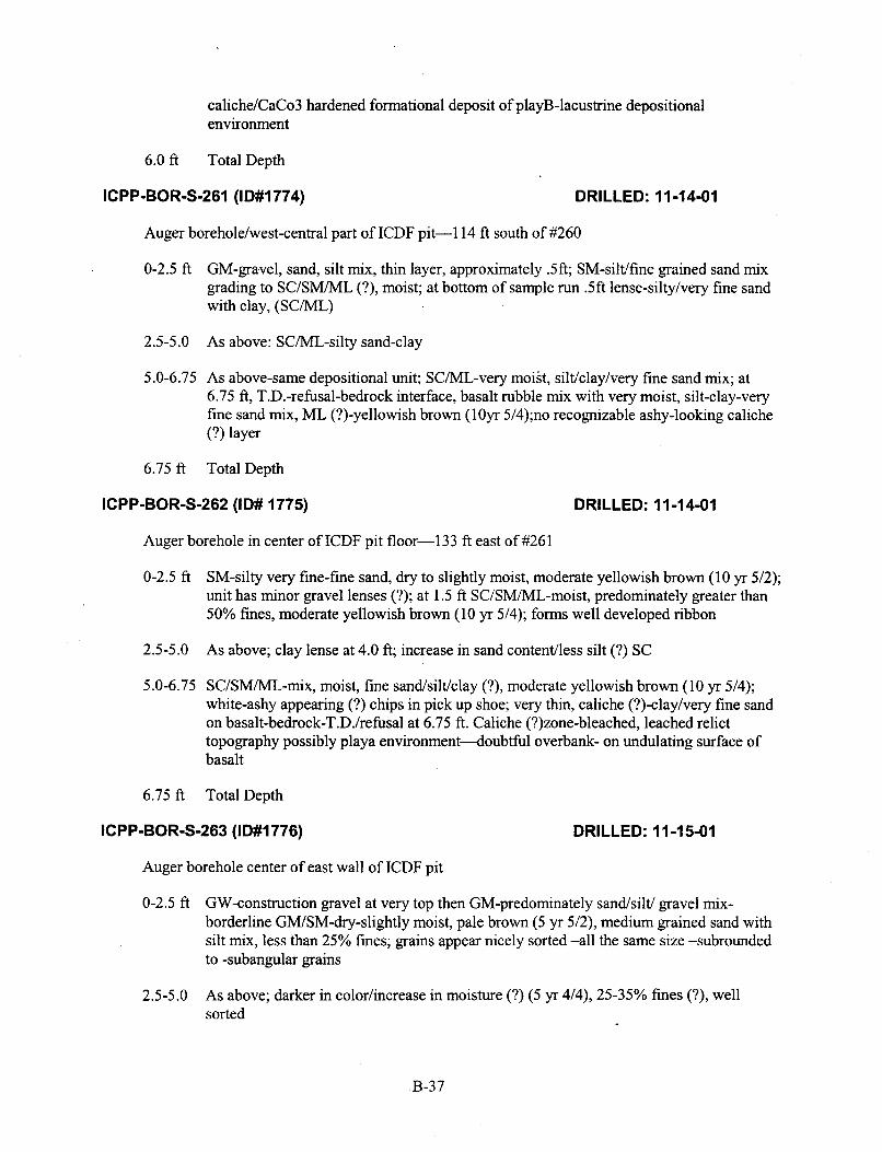
caliche/CaCo3 hardened formational deposit of playB-lacustrine depositional environment
6.0 ft Total Depth
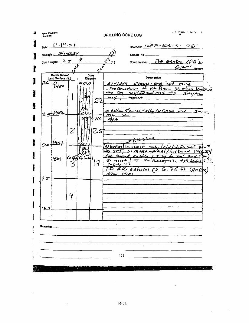
ICPP-BOR-S-261 (ID#l774) DRILLED: 11-14-01
Auger borehole/west-central part of ICDF pit-1 14 ft south of #260
0-2.5 ft GM-gravel, sand, silt mix, thin layer, approximately .5fi; SM-sil the grained sand mix grading to SC/SM/ML (?), moist; at bottom of sample run .5ft lense-silty/very fine sand with clay, (SCML)
2.5-5.0 As above: SC/ML-silty sand-clay
5 .O-6.75 As above-same depositional unit; SC/ML-very moist, silt/clay/very fine sand mix; at 6.75 ft, T.D.-refusal-bedrock interface, basalt rubble mix with very moist, silt-clay-very fine sand mix, ML (?)-yellowish brown (lOyr 5/4);no recognizable ashy-looking caliche (?) layer
6.75 ft Total Depth
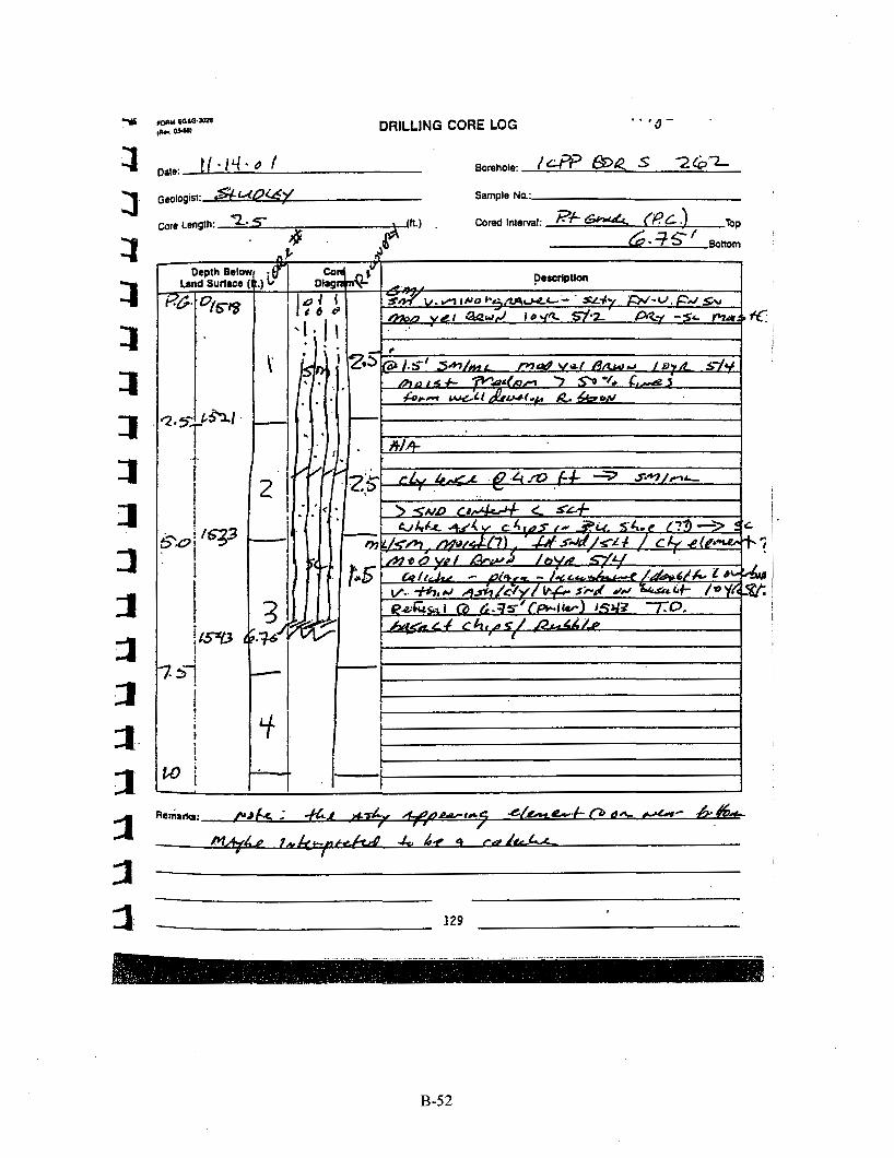
ICPP-BOR-S-262 (ID# 1775) DRILLED: 1 1-14-01
Auger borehole in center of ICDF pit floor-133 ft east of #261
0-2.5 ft SM-silty very fine-fine sand, dry to slightly moist, moderate yellowish brown (10 yr 5/2); unit has minor gravel lenses (?); at 1.5 ft SC/SM/ML-moist, predominately greater than 50% fines, moderate yellowish brown (10 yr 5/4); forms well developed ribbon
2.5-5.0 As above; clay lense at 4.0 ft; increase in sand content/less silt (?) SC
5.0-6.75 SC/SM/ML-mix, moist, fine sandsiltklay (?), moderate yellowish brown (10 yr 5/4); white-ashy appearing (?) chips in pick up shoe; very thin, caliche (?)-clayhery fine sand on basalt-bedrock-T.D./refusal at 6.75 ft. Caliche (?)zone-bleached, leached relict topography possibly playa environment4oubtful overbank- on undulating surface of basalt
6.75 ft Total Depth
ICPP-BOR-S-263 (ID#1776) DRILLED: 11 -1 5-01
Auger borehole center of east wall of ICDF pit
0-2.5 ft GW-construction gravel at very top then GM-predominately sandsiltl gravel mix- borderline GWSM-dry-slightly moist, pale brown (5 yr 5/2), medium grained sand with silt mix, less than 25% fines; grains appear nicely sorted -all the same size -subrounded to -subangular grains
2.5-5.0 As above; darker in color/increase in moisture (?) (5 yr 4/4), 25-35% fines (?), well sorted
B-37

5.0-7.5 As above, slightly moist to moist; at 6.lft SC/SM/ML (?)-very silty fine sand with clay element, slightly moist-moist, moderate yellowish brown (10 yr 5/4); sand is very fine to - fine grained, well sorted, greater than 50% fines-forms rough ribbon
7.5-8.15 As above; at 7.9 ft SC/ML-light color (10 yr 8/2), moist, very fine sandklay; sandklay unit rests on bedrock interface-basalt; at 8.15 ft-refusal-T.D
8.15 ft Total Depth
ICPP-BOR-S-264 (ID#l777) DRILLED: I 1 -15-01
Northeast corner and third auger borehole in series along north wall of ICDF pit-107 ft north of #263
0-2.5 ft GM-gravel, sand, silt, mix, slightly moist, moderate brown (10 yr 4/2); grading rapidly downward to SM-slightly moist, fine to -medium-grained sand, moderate yellowish brown (1 0 yr 5/4); section has gravel stringers
2.5-5.85 As above; at 4.3 ft SM- silty sand, slightly moist, yellowish orange-brown (10 yr 6/6), moderately well sorted with subrounded to subangular grains, 25% fines; forms short broken ribbon. Note: sample integrity for acquisition compromised-recovery 2.2 feet out of 2.5 foot run; however, refusalhedrock at 5.85 ft. logged only bottom .85ft of sample run. At approximately 5.4 ft SM/ML-whitish caliche-ashy appearing color (10 yr 8/2), very fine sandclay layer-caliche(?) formation environment (?) on bedrock interface- refusal-T.D. 5.85fi
5.85 ft Total Depth
ICPP-BOR-S-265 (ID#l778) DRILLED: 11 -1 5-01
Fourth auger borehole in series along north wall of ICDF pit-145 ft west of #264
0-2.5 ft GWSM-predominately very fine sand with gravel, 25% fines (?), dry, moderate yellowish brown (1 0 yr 5/4), nicely sorted, subrounded grains; at 1.5 ft SM-silty sand, slightly moist-moist, yellowish orange (10 yr 6/1), forms well developed-long ribbon (clay element)
2.5-5.1 Sandy gravel lense 2.5-3.0 ft; (possible slough from above?) at 3.0 ft SM-silty very fine sand, slightly moist-moist with siltlclay stringers, moderate yellowish brown (10 yr 5/4). At 4.1 ft SC/ML- yellowish grey color (5 yr 7/2 to 10 yr 8/2), slightly moist to moist, very fine grained sand/silt/clay-aswcaliche unit? Sample run is downward fining sequence. Refusal-T.D. at 5.1 ft-bedrock interfacehasalt
5.1 ft Total Depth
B-38

ICPP-BOR-S-266 (ID#l779) DRILLED: 1 1-1 5-01
Auger borehole at center of north wall/sump of ICDF pit-140 ft west of #265
0-2.5 ft SW/SM- dry, fine-grained, well sorted, subrounded to subangular, pale brown (5 yr 5/2). At 2.1 ft increase in silt content with possible clay element (SM/SC/ML?), slight moist, lighter color (1 0 yr 6/2), very fine sand-silt unit
2.5-5.0 ML (?)-grayish orange brown (10 yr 7/2), greater than 50% fines, very fine sand-silt, slightly moist to moist, clay element (?) appearing as fines, sample run has lighter color( 10 yr 6/2); streaks at bottom of sample run, forms rough ribbon
5 .O-7.15 As above; at 6.4 ft ML-clay, very light color (1 0 yr 8/2), ashy appearing-caliche(?)/clay unit, leachedhleached (?) relict topography (?), darker streaks last 0.4 ft, basaltMay mix (basalt element in fines); refusal-T.D. at 7.15 ft/no recovery in pick up shoe
7.15 ft Total Depth
ICPP-BOR-S-267 (ID#l780) DRILLED: 11-15-01
Final borehole in ICDF pit-103 ft south southeast of #265
0-2.5 ft GWSM mix, gradindfining downward to SM mix with gravel stringers, slightly moist- moist, pale brown (5 yr 5/2), fine to -medium-grained sand, less than 25% fines? Increase in silt content near bottom of sample run,
2.5-5.0 As above; at 2.9 ft SCML-very fine grained sandhilt with clay element (?), greater than 50% fines, slightly moist, forms nice ribbon but can feel grains, well sorted sand-silt size, moderate yellowish brown (1 0 yr 5/4)
5.0-6.35 GM-basalt gravel lense (?) SC/SM/ML-slightly moist, streaky color (grain size?), predominately SM with whitish layer right on top of bedrock. Refusal-T.D. at 6.35 ft. Note: no real identification on caliche-ashy loohng layer, could be absent? Definite grain size increase at bedrock interface; fine to medium grained sand in pick up shoe.
6.35 ft Total Depth
B-2.1.3 Summary
Cursory observation of the ICDF pit walls leads to an interpretation of an alluvial paleo-braided stream environment of deposition; however, external, as well as internal, criteria are subtle and would require a definitive investigation. Braiding commonly results where partially incompetent streams form longitudinal bars by depositing coarse elements of bed load which trap finer elements, which were exhibited in certain areas of the pit wall and as indicated by the poorly sorted-imbricated look. Also, transverse bars formed of better-sorted sediment are tabular and wedge-shaped. They may either be the only depositional form or may be deposited on downstream ends of longitudinal bars, thus, the better sorted “sand lenses” observed offset and/or juxtaposed to the poorly sorted appearing units traversing across the central north-south area of the ICDF pit walls.
The above observation is in contrast to the pit floor and predominantly represented in the lithology of the auger bore holes comprised of finer grained textures with appreciable amount of fines consisting of
B-39

fine grained sands, silts, and clay which indicate a different environment of deposition. Playa or inland lake environments of deposition exhibit similar lithology. This transition from alluvial systems to inland lake environments is readily observed in modem intramontane basins.
Inland playas are usually dried-up, vegetation-free, flat-floored areas composed of evenly stratified sheets of fine grained sand, silt, and clays; representing the bottom part of shallow, completely closed or undrained, desert lake basins in which water accumulates (as after a rain) and quickly evaporated, usually leaving deposits of soluble salts. It may be hard or soft, and smooth or rough. This environment is also prone to the development of caliche-which can be represented by gravel, rock, soil or alluvium cemented with soluble nitrate salts and calcium carbonate hardening.
The interpreted transition from braided stream to playa is represented in almost all of the auger bore holes-coarse, poorly sorted, gravel, sand, and silts to well sorted fined grained sand, silts and clays. This interpreted transition can be observed in the ICDF pit walls and pit floor-especially in the sump area.
The whitish very fine grained sandclay layer observed in several of the auger bore holes at the basalt-bedrock interface may be representative of a bleachedleached relict regolith with the subsequent formation of caliche.
B-40

B-2.2 Drilling Core Logs
DRILLING CORE LOG
107
B-41
1
I I
109
B-42

V e a l I& 9 DRILLING CORE LOG taw-- 6- - 4 4
111
B-43

* cu--- ,Rn Mu' DRILLING CORE LOG
Depth &low b n d Surface (t
!-- I
J- I 1
4
F- I I
l i i . t
113
B-44

r . r . * I DRILLING CORE LOG
I I I I I I I I I 1 I I I
V
I I
I
B-45

r7Gixz+ d Surface 1.) --
117
B-46

I --0- . DRILLING CORE LOG
- Depth Belc
Land Surfaca
i i i
ZSJ& I qp, . 5
I -c
2
-
3
- ct
2
B-47

VAF l0 . f I DRILLING CORE LOG
3 - 121
. . . ... ... ~
B-48

B
1 I I I 1 I I I I I I i I
DRILLING CORE LOG
7 b n d Suflacc
I
I
i I
knarks:
123
B-49

P
I D f I i I I I I I I I I I I I I
I
r e a p I ‘ I I
DRILLING CORE LOG
I I c
Remarks:
125
B-50
II I 1 11. I i I. I I I I I
,cQau Ea.==- -- DRILLING CORE LOG “’-7 - w ” ’
I I I I I i JJ I i
I l l I
127
B-5 1
I 11 .LhI
2 1
129
B-52

DRILLING CORE LOG
Borehole: / c P f l - AD&- s - 3 6 3 _.
. Geologist: ~f&dde+/ Sample No.: .-.*a
Core Length z s Cored Interval:
- k A 4 P
1 i -P t.
!
I
3 I
I 1
B-53

DRILLING CORE LOG
Y
Depth Below
ri I I
Li I I
B-54

DRILLING CORE LOG
Date: / / - K - Q /
Geologist: Skta&C/ Core Length: 2- s- 4 (k)
3 A Y ' aottom
0
131
B-55

DRILLING CORE LOG m u ECLGJon .; i n n oswi
t I
i I
B-56

.-
DRILLING CORE LOG fft$ 1 d . F
Date: I/- /3--0 1 Borehole:
Geologist 5-q - Sample No.: I
I "i
t
I I I r I t -
. !
B-57

6-2.3 ASTM Standard D 2487, United Soil Classification System
The following pages describe the ASTM Unified Soil Classification System.
Designation: D 2487 - 00 4sIb Standard Practice for Classification of Soils for Engineering Purposes (Unified Soil Classification System)'
1. Scope 1.1 This practice describes a system for classifying mineral
and organo-mineral soils for engineering purposes based on laboratory determination of panicle-size characteristics, liquid limit, and plasticity index and shall be used when precise classification is required.
N m I-list ofhis standard will rcsulr in a singlc classification group symbol and group name except when II rail contains 5 to IZoA1 fines or whcn thc plot 0 1 the liquid limit and plasticii> mdey wlucs falls into thc crosshatched area olthc plarixity clvnn. 111 thcrc I U U &bc.,. dual ,ytnhul is uscd. for example. GP-GM. CL-ML. When ihc Inborntory test results indicate that the soil hr close to ilnothcr soil clarrlticstion group. the borderline condition can bc indicated with IWO syrnbolr repatatcd by a slash. The first symbol should bc the one based on this standard. for example, CL'CH. GWSM. SUCL. Bordcrlinc symbols arc paniculnrly uscful whcn the liquid limit value ofclaycy soils is close to 50, These soils can haw cxpansivc chvancrisiics and the ux of a borderline symbol [CUCH, CWCL) will alen the user of the assigned classifications of expansive potential.
1.2 The group symbol ponion of this system is based on laboratory tests performed on the portion of a soil sample passing the 3411. (75-mm) sieve (see Specification E I I ) .
1.3 As a classification system, this standard is limited to naturally occurring soils.
NOTE 2-The group M ~ C F and symbols uscd in this ISI method may be used as a descriptive system applied to such materials as shale. claystone. shells. cnrrhed rock. etc. Sa Appendix X2.
1.4 This standard is for qualitative application only.
NOTE 3-When quantitative information is required for detailed de- signs of important SUUCN~CS. this test mthad must k supplcmcntcd by laboratory lesa or other quantitative data to determine psdmnance characteristics under expected field conditions.
1.5 This standard is the ASTM version of the Unified Soil Classification System. The basis for the classilicaiion scheme is the Airfield Classification System developed by A. Casa- grande in the early 1940'sJ I t became known as the Untlied
Soil Classification System when several US. Government Agencies adopted a modified version of the Airfield System in 19.52.
I .6 This standard does not purporf 10 address all OJ the saJety concerns. i/ any, msociared with ifs use. If IS fhe responsibility OJ the user of this standard to establish appm- priate safely and health practices and determine the applica- bili1.v o/ regulatory limitations prior 10 use
I .7 Thh pructice qflers a set o/ instruc~ions /or perfirming OIIC, 01. i i i ~we r p r c rhc operuiiom. This document cannoi replace rducatroii or experience and should not be used in conjunction wirh prfi/rssiiinal judgment. Not all aspects olthis practice may be upplicable in all circumstances. This ASTM standard is not intended to represent or replace the standard of care by which the adequac)' oJa given professional service musf be judged. nor should fhis documenf be applied without consideration o/ a project 's many unique aspects. The word "Standard" in the fitle oJthis document means only rhaf the documenf has been approved fhroush the ASTM consensus process.
2. Referenced Documents 2. I ASTM Standards. C 117 Test Method for Materials Finer Than 7 5 y m (No.
200) Sieve in Mineral Aggregates by Washing' C 136 Test Method for Sieve Analysis of Fine and Coarse
Aggregates' C 702 Practice for Reducing Field Samples ofAggregate to
Testing Size' D 420 Guide to Site Characterization for Engineering, Dc-
sign and Construction Purposes D421 Practice for Dry Preparation of Soil Samples for
Particle-Size Analysis and Determination of Soil Con- s t a n t ~ ~
D 422 Tesl Method for Parlicle-Size Analysis of Soils4 D h53 Terminology Relating to Soil, Rock, and Contained
D I I40 Test Method for Amount of Material in Soils Finer Fluids'
than the No. 200 (75-pm) Sieve4
(Moisture) Content of Soil and Rock4
' This standard -1 mdn Urjunrdietm of ASTM Commitac D-In OD Soil aml Rak and 81 L e drmt msporu,bilily o f Subcmmillse DI8 07 on ldmiihitmn and
Cumen1 cditian ap~mved Marsh 10. 2000 Publuhcd May 2 M o Oneilullr
2216 Method for Laboratory De'erminat1on Of Water Chrnhal,on of Salt,
- . published as D 2417 -.66 T. Last prcviovp cditim D 2487 - 98
ASCE. 1948. p. W I ' C p w ~ w k . A. "Cbrnhcmon md Idatiiirutm of Soh." r r a ~ m # o n r . 'Annun! Book o / A S M Stmiads. Vol u0.02.
Annud Book o/AST.U Stundunlr. VoluO.08.
COPYRIGHT 2000 American Society lnfmaiion Handling Sewkes. ZOO0
fw Testing and Material$
B-58

dm D 2487
D 2217 Practice for Wet Preparation of Soil Samples for Particle-Size Analysis and Determination of Soil Con- slants4
D 2488 Practice for Description and Identification of Soils (Visual-Manual Pr~cedure.)~
D 3740 Practice for Minimum Requirements for Agencies Engaged in the Testing and/or Inspection of Soil and Rock as Used in Engineering Design and Construction’
D 4083 Practice for Description of Frozen Soils (Visual- Manual Proced~re)~
D4318 Test Method for Liquid Limit, Plastic Limit, and Plasticity Index of Soils4
D 4427 Classification of Peat Samples by Laboratory Test- ing4
E 1 I Specification for Wire-Cloth Sieves for Testing Pur- poses6
3. Terminology 3.1 Definirions-Except as listed below, all definitions are
in accordance with Terminology D 653.
NoTt &For particles retained on a 3-in. (75-mm) U.S. standard sieve. the following definitions are suggested:
Cubbles-panicles of rock that will pass a 12-in. (300-min) square opening and be retained on a 3411. (754111) U.S. standard sieve. and
Boulders-particles of rock that will not pass a 1 2 4 % (300-mrn) square opening.
3.1.1 clay-soil passing a No. 200 (75-pm) U S . standard sieve that can be made to exhibit plasticity (putty-like proper- ties) within a range of water contents and that exhibits considerable strength when air dry. For classification. a clay is a fine-grained soil, or the fine-grained portion of a soil, with a plasticity index equal to or greater than 4, and the plot of plasticity index versus liquid limit falls on or above the “A” line.
3.1.2 gruveCparticles of rock that will pass a 3-111 (75- mm) sieve and be retained on a No. 4 (4.75-mm) U.S. standard sieve with the following subdivisions:
Coarse-passes 3-in. (75-mm) sieve and retained on .‘/-in.
Fine-passes 3A-in. (19-mm) sieve and retained on No. 4 (19-mm) sieve, and
(4.75-mm) sieve.
’ Anntrul Book oJASTM Siundaniv. Vol 04.09. ’Annuul Book ofASTM Sumdunis. Vol 14.02.
3. I .3 orgunic cluy-a clay with sufficient organic content to influence the soil properties. For classification, an organic clay is a soil that would be classified as a clay except that its liquid limit value aiier oven drying is less than 75 % o f its liquid limit value before oven drying.
3. I .4 urgonic silr-a silt with sufficient organic content to influence the soil properties. For classification, an organic silt is a soil that would be classified as a silt except that its liquid limit value after oven drying is less than 75 % o f its liquid limit value before oven drying.
3.1.5 prar-a soil composed of vegetable tissue in various wages of decomposition usually with an organic odor, a dark-brown to black color, a spongy consistency, and a texture ranging from fibrous to amorphous.
3.1.6 sand-particles of rock that will pass a No. 4 (4.75- mm) sieve and be retained on a No. 200 (75-pm) U S . standard sieve with the following subdivisions:
Coarse-passes No. 4 (4.75-mm) sieve and retained on No. IO (2.00-mm) sieve,
Medium-passes No. IO (2.00-mm) sieve and retained on No. 40 (425-pm) sieve, and
Fine-passes No. 40 (425-pm) sieve and retained on No. 200 (75-pm) sieve.
3.1.7 silr-soil passing a No. 200 (75-pm) U.S. standard sieve that is nonplastic or very slightly plastic and that exhibits little or no strength when air dry. For classification, a silt is a fine-grained soil, or the fine-grained portion of a soil, with a plasticity index less than 4 or if the plot of plasticity index versus liquid limit falls below the “A” line.
3.2 Definitions of’Terms Specific to This Standard: 3.2.1 coeJicient of curvature. Cc-the ratio (Dip)'/
(Di, X D,,), where D,, D,,, and D,, are the particle sizes corresponding to 60, 30, and 10 % finer on the cumulative particle-size distribution curve, respectively.
3.2 2 cwficieur o/uni/brmiy. Cu-the ratio D,JD,,,, where D,* and D,,, are the panicle diameters corresponding to 60 and I O YO finer on the cumulative particle-size distribution curve, respectively. 4. Summary
4.1 As illustrated in Table 1, this classification system identifies three major soil divisions: coarse-grained soils, fine-grained soils, and highly organic soils. These three divi- sions are further subdivided into a total of 15 basic soil groups.
TABLE 1 Soil Classification Chart
Sod Classficalion Group Name’ Group Symbol Criteria for Assigning Group Symbols and Group Names Uslng Laboratory Tests“
COARSE-GRAINED Gravels Clean Gravels Cu 2 4 and OW Well-graded gravel0 SOILS 1 c c c r 3 c Mwe than 50 % More than 50 % of Less man 5 % fines‘ C u c 4 a d w GP Poofly graded gravelD retained on No w a r w f r ahn ! > C C = ~ ~ 200 sieve relained on No. 4
sieve Gravels wilh Fines Fines classify as ML GM S i b gravelO,F.w
More than 12 % finesE Fines classih, as CL or .urule:l>GC Clayey gravelD,F.G
Sands Clean Sands c u 2 6 and sw Well-gradsd sandM
or MH
CH
1 c cc 5 3=
COPYRIGHT 2000 American Society for Testing and Materials Information Handling Services, 2000
B-59

TABLE I Continued Soil Classificahon
Gmup Symbol Group Name' Critena for Assigning Group Symbols and Gmup Names Usmg Laboratory TestsA Poorly graded rand" 50 % or m e of Less than 5 % fines' Cu c 6 and/or ' SP
coarse fraction passes No. 4 Sands with Fines Fines classify as ML SM Silty sandF.C.H
sieva or MH Clayey sandF.=." More than 12 X fines' Fines classity as CL or sc
CH
above 'A' line' FINE-GRAINED Sills and Clays inorganic PI > 7 and plots on cf CL Lean day".L.U SOILS 50 X or more passes Liquid limit less than PI c 4 or plots below ML .?.ill".'." the No. 50 -K tine' 200 seive organic LiQUid limit - oven OL Organic clay''.L.M.N
Liquid limit - not dried OL Organic siltn,L.Y.o dried> ~ 0 7 5
Silts and Clays inorganic ' PI plots on or above CH Fa1 'A' ltne
Liquid limit 50 or more PI plols below "A' line MH Elastic siltx/.Y organic Liauid lhmit -oven OH Organic clay".L.U.P
dried C O . 7 5 Liquid limit - not dried Organic silF,L.M."
HIGHLY ORGANIC Primarily organic matter. dark in color. and organic odor PT Peat . - SOILS
A Based on the material parsing the 3-in (75mm) sieve.
'Cu = D d I o
E Gravels wilh 5 to TZ % fines require dual symbols
field sample contained cobbles or boulders. or bolh. add "with cobbles or boulders. or both" to group name. CC = (Dxf /D,o x Dm
If soil contains a15 % sand, add 'with sand' to group name
GW-GM well-graaed gravel mth silt GW-GC well-graoed gravel with clay GP-GM p o w graded gravel with silt GP-GC poorly graded yavel with clay If fines classtty as CL-ML. use dual symbol GC-GM, of SC-SM If Dnes are organic, add Wilh organic fines' to group name
" I f so11 contains 215 % gravel, add W l h gravel' to youp name. 'Sands with 5 lo 12 X fines require dual symbols:
SW-SM wellgraded sand wilh silt SW-SC wellgraded sand with clay SP-SM p c a y graded sand with sill SP-SC pc4y graded sand with clay
'If Alterberg limits plot in hatched area, soil is a CL-ML. silly clay. " I f soil conlains 15 to 29 % plus No. 200. add 'with sand" or 'with gravel.' whichever IS predominant
" If soil contains a30 % plus No. 200. predominantly gravel, add 'gravelly" to group name If 5011 contains a30 X plus No. 2W. predominantly sand, add -sand to group name
PI 2 4 and plots on or above "A" line. PI c 4 cf plots below' A" line. PI plots on or a w e 'A" line.
O PI plots below "A- line
4.2 Based on the results of visual observations and pre- scribed laboratory tests, a soil is catalogued according to the basic soil groups, assigned a group symbol(s) and name, and thereby classified. The flow charts, Fig. 1 for fine-grained soils, and Fig. 3 for coarse-grained soils, can be used to assign the appropriate group symbol(s) and name.
5. Significance and Use 5. I This standard classifies soils from any geographic loca-
tion into categories representing the reiults 01' preisribeii laboratory tests to determine the particle-size characteristics, the liquid limit, and the plasticity index.
5.2 The assigning of a group name and symbol(s) along with the descriptive information required in Practice D 2488 can be used to describe a soil to aid in the evaluation of its significant properties for engineering use.
5.3 The various groupings of this classification system have been devised to correlate in a general way with the engineering behavior of soils. This standard provides a useful first step in
any field or laboratory investigation for geotechnical engineer- ing purposes.
5.4 This standard may also be used as an aid in training personnel in the use of Practice D 2488.
5.5 This standard may be used in combination with Practice D 4083 when working with frozen soils.
N t m 5-Kotwithstanding the statements on precision and bias con- tained in this standard The precision of this test method is dependent on thc cciinpctencc of the personncl performing it and the suitability of the squipillcin and I;iuiliiics used. Agencius that inert the criteria of Practice D 3740 are generally considered capable o f competent and objective testing. Users o f this test method are cautioned that compliance with Practice D 3740 d w s not in itself assure reliable testing. Reliable resting depends on several factors; Practice D3740 provides a means for evaluating some o f those factors.
6. Apparatus
6.1 In addition to the apparatus that may be required for obtaining and preparing the samples and conducting the prescribed laboratory tests, a plasticity chart, similar to Fig. 4,
3
COPYRIGHT 2000 American Society for Testing and Materials Information Handling Services, 2000
B-60

QROUP SYMBOL GROUP NAME
/ \
-OH -5.. tiin lb
FIG. 1 Flow Chart for Classifying Fine-Grained Soil (50 *A or More Passes No. 200 Sieve)
and a cumulative particle-size distribution curve, similar to Fig. 5 , are required.
Non &The " U line shown on Fig. 4 has been empirically deter- mined to be the approximate "upper limit" for nalurdl soils I 1 i s :I good check against erroneous data. and any tcst rcsulh tlial plot ilbovc or IO thc Icfl of it should be verified.
7. Sampling 7.1 Samples shall be obtained and identified in accordance
with a method or methods, recommended in Guide D 420 or by other accepted procedures.
7.2 For accurate identification, the minimum amount of test sample required for this test method will depend on which of the laboratory tests need to be performed. Where only the particle-size analysis of the sample is required, specimens having the following minimum dry weights are required:
Maximum Panicle Size. Sieve Opening Dry Weight
4.75 mrn (No. 4) 9.5 mm (ub in ) 19.0 mm (?A in.)
38.1 mm (l%in.) 75.0 mm (3 in.)
Minimum Specimen Size.
100 g (0.25 Ib) 200 g (0.5 Ib) 1.0 kg (2.2 Ib) 8.0 kg (18 Ib)
60.0 kg (132 Ib)
Whenever possible, the field samples should have weights two to four times larger than shown.
7.3 When the liquid and plastic limit tests must also be performed, additional material will be required sufficient to
provide I50 g to 200 g of soil finer than the No. 40 (425-pm) sieve.
7.4 If the field sample or test specimen is smaller than the minimum recommended amount. the report shall include an appropriaie rrmdrk
8. Classification of Peat 8.1 A sample composed primarily of vegetable tissue in
various stages of decomposition and has a fibrous to amor- phous texture, a dark-brown to black color, and an organic odor should be designated as a highly organic soil and shall be classified as peat, PT, and not subjected to the classification procedures described hereafter.
8.2 If desired, classification of type of peat can be per- formed in accordance with Classification D 4427.
9. Preparation for Classification 9. I Before a soil can be classified according to this standard,
generally the particle-size distribution of the minus 3-in. (75-mm) material and the plasticity characteristics of the minus No. 40 (425-pm) sieve material must be determined. See 9.8 for the specific required tests.
9.2 The preparation of the soil specimen(s) and the testing for particle-size distribution and liquid limit and plasticity index shall be in accordance with accepted standard proce- dures. Two procedures for preparation of the soil specimens for
4
COPYRIGHT 2000 American Society for Testing and Materials Information Handling Services, 2000
B-61

GROUP SYMBOL
testing for soil classification purposes are given 111 Appendixes X3 and X4. Appendix X3 describes the wet preparation method and is the preferred method for cohesive soils that have never dried out and for organic soils.
9.3 When reporting soil classifications determined by this standard, the preparation and test procedures used shall be reported or referenced.
9.4 Although the test procedure used in determining the particle-size distribution or other considerations may require a hydrometer analysis of the material, a hydrometer analysis is not necessary for soil classification.
9.5 The percentage (by dry weight) of any plus 3-in. (75-mm) material must be determined and reported as auxiliary information.
9.6 The maximum particle size shall be determined (mea- sured or estimated) and reported as auxiliary information.
9.7 When the cumulative .particle-size distribution is re- quired, a set of sieves shall be used which include the following sizes (with the largest size commensurate with the maximum particle size) with other sieve sizes as needed or required to define the particle-size distribution: 3-in (75-mm) Yd-in (19.0-mm) No 4 (4.75-mm) No. 10 (2.W-mm) No 40 (425-11m) NO. 200 (75-vm)
9.8 The tests required to be performed in preparation for classification are as follows:
9.8.1 For soils estimated to contain less than 5 YO fines, a plot of the cumulative particle-size distribution curve of the fraction coarser than the No. 200 (7591) sieve is required. A semi-log plot of percent passing versus partical-size or sieve sizehieve number is plotted as shown in Fig. 5 .
Y.8.2 For soils estimated to conlain 5 to 15 % fines, a cumulative particle-sire distribution curve, as described in 9.8.1, is required, and the liquid limit and plasticity index are required.
9.8.2. I If suficient material is not available to determine the liquid limit and plasticity index, the fines should be estimated to be either silty or clayey using the procedures described in Practice D 2488 and so noted in the report.
9.8.3 For soils estimated to contain 15 % or more fines, a determination of the percent fines, percent sand, and percent gravel is required, and the liquid limit and plasticity index are required. For soils estimated to contain 90 % fines or more, the percent fines, percent sand, and percent gravel may be esti- mated using the procedures described in Practice D 2488 and so noted in the report.
IO. Preliminary Classification Procedure 10.1 Class the soil as fine-grained if 50 YO or more by dry
weight of the test specimen passes the No. 200 (75-pn) sieve and follow Section 3. I .2.
10.2 Class the soil as coarse-grained if more than 50 YO by dry weight of the test specimen is retained on the No. 200 (75-pm) sieve and follow Section 12.
11. Procedure for Classification of Fine-Grained Soils (50 'Yn or more by dry weight passing the No. 200 (75- pm) sieve)
I I . I The soil is an inorganic clay if the position of the plasticity index versus liquid limit plot, Fig. 4, falls on or above the "A" line, the plasticity index is greater than 4, and the presence of organic matter does not influence the liquid limit as determined in 11.3.2.
Nmt 7-The plasticity index and liquid limit are determined on the
5
COPYRIGHT 2000 American Society for Testing and Malerials Information Handling Services, 2000
B-62
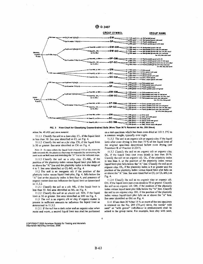
4@ D 2487
GROUP SYMBOL QROUP NAME
minus No. 40 (425 pm) sieve material.
is less than 50. See area identified as CL on Fig. 4.
is 50 or greater. See area identified as CH on Fig. 4. NoTt 8-In cues where thc liquid Iinlir csceeds I IO or the plesllclIy
index exceeds 60. the plasticity chart may be expandcd by maintaining the same scale on both axes and extending the ”A” line at the indicated slopc.
11.1.3 Classify the soil as a silty clay. CL-ML, if the position of the plasticity index versus liquid limit plot falls on or above the “A” line and the plasticity index is in the range of 4 to 7. See area identified as CL-ML on Fig. 4.
11.2 The soil is an inorganic silt if the position of the plasticity index versus liquid limit plot, Fig. 4. falls below the “A” line or the plasticity index is less than 4, and presence of organic matter does not influence the liquid limit as determined in 11.3.2.
11.2.1 Classify the soil as a silt, ML, if the liquid limit is less than 50. See area identified as ML on Fig. 4.
11.2.2 Classify the soil as an elastic silt, MH, if the liquid limit is 50 or greater. See area identified as MH on Fig. 4.
11.3 The soil is an organic silt or clay if organic matter is present in sufficient amounts to influence the liquid limit as determined in 11.3.2.
11.3.1 If the soil has a dark color and an organic odor when moist and warm, a second liquid limit test shall be performed
1 I . I . I Classify the soil as a lean clay, CL, if the liquid limit
11 . I .2 Classify the soil as a fur clay, CH, if the liquid limit
on a test specimen which has been oven dried at 110 t 5°C to a constant weight, typically over night.
11.3.2 The soil is an organic silt or organic clay if the liquid limit after oven drying is less than 75 YO of the liquid limit of the original specimen determined before oven drying (see Procedure B of Praclice D 2217).
I 1.3.3 Classify the soil as an orgunic sill or organic cluy, OL, if the liquid limit (not oven dried) is less than 50%. Classify the soil as an organic silt. OL, if the plasticity index is less than 4, or the position of the plasticity index versus liquid limit plot falls below the “A” line. Classify the soil as an organic clay, OL, if the plasticity index is 4 or greater and the position of the plasticity index versus liquid limit plot falls on or above the “A” line. See area identified as OL (or CL-ML) on Fig. 4.
11.3.4 Classify the soil as an organic clay or organic silt. OH. if the liquid limit (not oven dried) is 50 or greater. Classify the soil as an organic silr, OH, if the position of the plasticity index versus liquid limit plot falls below the “A” line. Classify the soil as an organic clay, OH, if the position of the plasticity index versus liquid-limit plot falls on or above the “A” line. See area identified as OH on Fig. 4.
11.4 If less than 30 YO but 15 % or more of the test specimen is retained on the No. 200 (75-pm) sieve, the words“ with sand” or “with gravel” (whichever is predominant) shall be added to the group name. For example, lean clay with sand,
6
COPYRIGHT 2000 American Society for Testing and Materials Information Handling Services. 2000
B-63

60
50 a X W
z >- k 30 0 k v)
-I
v
a 40 -
- a zc a
10 7 4
0
LIQUID L I M I T (LL) FIG. 4 Plasticity Chart
S I E V E A N A L Y S I S
I 1 S C R E E N - I N S I E V E NO.
3 2 17, I v. v, 4 IO 20 40 60 140 200 100
Q
v)
5 60
a I - $ 40 V E w a 20
0.075
0 I . , , 1 . , , 1 1 < , I , , , , I C , I
5c IO 5 1.0 0.5 0 10
PARTICLE S I Z E I N M I L L I M E T R E S
D,o 0.075
FIG. 5 Cumulative Particle-Sire Plot
CL; silt with gravel, ML. If the percent of sand is equal to the percent of gravel, use “with sand.”
11.5 If 30 % or more of the test specimen is retained on the No. 200 (75-pm) sieve, the words “sandy” or“ gravelly” shall
be added to the group name. Add the word “sandy” if 30 Yo or more of the test specimen is retained on the No. 200 (75-pm) sieve and the coarse-grained portion is predominantly sand. Add the word “gravelly” if 30 YO or more of the test specimen
COPYRIGHT 2000 American Society for Testing and Materials Information Handling Services. 2000
B-64

is retained on the No. 200 (75ym) sieve and the coarse-grained portion is predominantly gravel. For example, sandy lean clay. CL; gravelly fat clay, CH; sandy silt, ML. If the percent of sand is equal to the percent of gravel, use ”sandy.”
12. Procedure for Classification of Coarse-Grained Soils (more than 50 YO retained on the No. 200 (75-pm) sieve)
12.1 Class the soil as gravel if more than 50 % of the coarse fraction [plus No. 200 (75-pm) sieve] is retained on the No. 4 (4.75-mm) sieve.
12.2 Class the soil as sand if 50 YO or more of the coarse fraction [plus No. 200 (75-pm) sieve] passes the No. 4 (4.75-inm) sieve,
12.3 If 12 % or less of the test specimen passes the No. 200 (75-pm) sieve, plot the cumulative particle-size distribution, Fig. 5, and compute the coeficient of unilormity. Cu. and coefficient of curvature, Cc, as given i n Eqs I and 2.
Cu=D,qD,, ( 1 )
C C = ( D ~ , ) ~ ( D , , X D ~ ) (2)
where: DIU. D,,, and D, = the particle-size diameters correspond-
ing to 10, 30, and 60 %, respectively, passing on the cumula- tive particle-size distribution curve, Fig. 5.
NOTE 9 - 1 1 may be necessary to extrapolate thc curve to obtain the D,,, diameter.
12.3. I If less than 5 % of the test specimen passes the No. 200 (75-pm) sieve, classify the soil as a well-graded gravel. GW, or well-gradedsand, SW, if Cu is greater than or equal to 4.0 for gravel or greater than 6.0 for sand, and Cc is at least I .O but not more than 3.0.
12.3.2 If less than 5 YO of the test specimen passes the No. 200 (75-pm) sieve, classify the soil as poorly graded grovel, GP, or poorly graded sand, SP, if either the Cu or the Cc criteria for well-graded soils are not satisfied.
12.4 If more than I2 % of the test specimen passes the No. 200 (75-pm) sieve, the soil shall be considered a coarse- grained soil with fines. The fines are determined to be either clayey or silty based on the plasticity index versus liquid limit plot on Fig. 4. (See 9.8.2.1 if insufficient material available Tor testing) (see Note 7).
12.4.1 Classify the soil as a claye-v grove/, GC. or c/qe,r sand. SC, if the fines are clayey, that is. the position of the plasticity index versus liquid limit plot, Fig. 4, falls on or above the “A” line and the plasticity index is greater than 7.
12.4.2 Classify the soil as a silty gravel. GM, or silfy sand, SM, if the fines are silty, that is, the position of the plasticity index versus liquid limit plot, Fig. 4, falls below the “A” line or the plasticity index is less than 4.
12.4.3 If the fines plot as a silty clay, CL-ML, classify the soil as a d r y , clayey gravel, GC-GM, if i t is a gravel or a silly, clayey sand, SC-SM, if it is a sand.
12.5 If 5 to 12 YO of the test specimen passes the No. 200 (75-pm) sieve, give the soil a dual classification using two group symbols.
12.5. I The first group symbol shall correspond to that for a gravel or sand having less than 5 YO fines (GW, GP, SW, SP), and the second symbol shall correspond to a gravel or sand having more than I2 % fines (GC, GM, SC, SM).
12.5.2 The group name shall correspond to the first group symbol plus “with clay” or “with silt” to indicate the plasticity characteristics of the fines. For example, well-graded gravel with clay, GW-GC; poorly graded sand with silt, SP-SM (Sec 9.8.2. I if insufficient material available for testing).
Nmt IO-If the fines plot as J si/@ c1u.v. CL-ML. the second group symbol should be either GC or SC. For example, J poorly graded sand with 10 % fines, a liquid limit of 20, and a plasticity index of 6 would be classified as a poorly graded sand with silty clay. SP-SC.
12.6 I f the specimen is predominantly sand or gravel but contains I5 YU or more of the other coarse-grained constituent, the words ”with gravel” or “with sand” shall be added to the group name. For example, poorly graded gravel with sand, clayey sand with gravel.
12.7 If the field sample contained any cobbles or boulders or both, the words “with cobbles,” or “with cobbles and boulders” shall be added to the group name. For example, silty gravel with cobbles, G.M.
13. Report
13.1 The report should include the group name, group symbol, and the results of the laboratory tests. The particle-size distribution shall be given in terms of percent of gravel, sand, and fines. The plot of the cumulative particle-size distribution curve shall be reported if used in classifying the soil. Report appropriate descriptive information according to the proce- dures in Practice D 2488. A local or commercial name or geologic interpretation for the material may be added at the end of the descriptive information if identified as such. The test procedures used shall be referenced.
NOTE I I-Example: Cluyey Grovel with Sand und Co66lr.s (tic)- 46 % fine to coarse, hard, subrounded gravel; 30 % fine to coarse, hard, subrounded sand; 24 % clayey fines. LL = 38, PI = 19; weak reaction with HCI; original ficld sample had 4 % hard, subrounded cobbles; maxiiiiuiii dimension I50 mm.
In-Place Conditions-firm, homogeneous, dry, brown, Geologic Interpretation-alluvial fan.
NoTt 12-Other examples of soil descriptions are given in Appendix XI.
14. Precision and Bias
bias ofTest Methods D422, D 1140 and D4318. 14. I Criteria for acceptability depends on the precision and
15. Keywords
15. 1 Attcrberg limits; classification; clay; gradation; gravel; laboratory classification; organic soils; sand; silt; soil classifi- cation; soil tests
8
COPYRIGHT 2000 American Society for Testing and Materials Information Handling Services, Zoo0
B-65

(@I D 2487
APPENDIXES
(Nonmandatory Information)
X1. EXAiMPLES O f DESCHlPTlOIb LSlhC SOIL CLASSIFICATIOY
XI.l The following examples show how the information required in 13.1 can be reported. The appropriate descriptive information from Practice D 2488 is included for illustrative purposes. The additional descriptive terms that would accom- pany the soil classification should be based on the intended use of the classification and the individual circumstances.
X 1. I , 1 Well-Graded Gravel with Sand (GW)-73 % fine to coarse, hard, subangular gravel; 23 5’0 fine to coarse, hard, subangular sand; 4 % fines; Cc = 2.7, Cu = 12.4.
X I . I .2 Sily Sand with Gravel (SM)-6 I ?4 predominantly fine sand; 23 % silty fines, LL = 33, PI = 6; 16 YO fine, hard, subrounded gravel; no reaction with HCI; (field sample smaller than recommended). In-Place Condifions-Firm, stratified and contains lenses of silt 1 to 2 in. thick, moist, brown to gray; in-place density = 106 Ib/ft’ and in-place moisture = 9 %.
X1.1.3 Organic Clay (OL)-l00 YO fines. LL (not dried) = 32, LL (oven dried) = 21, PI (not dried) = IO; wet. dark brown, organic odor, weak reaction with HCI.
X1.1.4 Silty Sand with Organic Fines (SMj-74 % fine to coarse, hard, subangular reddish sand; 26 YO organic and silty dark-brown fines, LL (not dried) = 37, LL (oven dried) = 26, PI (not dried) = 6, wet, weak reaction with HCI.
XI. 1.5 Poorly Graded Gravel wirh Silt, Sand, Cobbles and Boulders (GP-GM)-78 % fine to coarse, hard, subrounded to subangular gravel; 16 % fine to coarse, hard, subrounded lo subangular sand; 6 % silty (estimated) fines; moist, brown; no reaction with HCI; original field sample had 7 % hard, sub- rounded cobbles and 2 % hard, subrounded boulders with a maximum dimension of 18 in.
X2. USING SOIL CLASSIFICATION AS A DESCRIPTIVE SYSTEM FOR SHALE, CLAYSTONE, SHELLS, SLAG, CRUSHED ROCK, ETC.
X2.1 The group names and symbols used in this standard may be used as a descriptive system applied to materials that exist in situ as shale, claystone, sandstone, siltsioiie, mudstone. etc.. but convert to soils after field or laboratory processing (crushing, slaking, etc.).
X2.2 Materials such as shells, crushed rock, slag, etc., should be identified as such. However, the procedures used in this standard for describing the particle size and plasticity characteristics may be used in the description of the material. If desired, a classification in accordance with this standard may be assigned to aid in describing the material.
X2.3 If a classification is used, the group symbol(s) and group names should be placed in quotation marks or noted with some type of distinguishing symbol. See examples.
X2.4 Examples of how soil classifications could be incorporated into a description system for materials that are not naturally occurring soils are as follows:
X2.4.1 Shale Chunks-Retrieved as 2- to 4-in. pieces of shale from power auger hole, dry, brown, no reaction with HCI.
After laboratory processing by slaking in water for 24 h, material classified as “Sandy Lean Clay (CL)”-61 YO clayey lines, LL = 37, PI = 16; 33 V I fine to medium sand; 6 % gravel-size pieces of shale.
X2.4.2 Crushed Sandstone-Product of commercial crush- ing operation; “Poorly Graded Sand with Silt (SP-SM)”-91 % fine to medium sand; 9 % silty (estimated) fines; dry, reddish- brown, strong reaction with HCI.
X2.4.3 Broken Shefls-62 % gravel-size broken shells; 31 % sand and sand-size shell pieces; 7 % fines; would be classified as “Poorly Graded Gravel with Sand (GP)”.
X2.4.4 Crushed Rock-Processed gravel and cobbles from Pit No. 7; “Poorly Graded Gravel (GP)”-89 % fine, hard, angular gravel-size particles; 11 % coarse, hard, angular sand- size particles, dry, tan; no reaction with HCI; Cc = 2.4, cu = O.Y.
X3. PREPARATION AlVD TESTING FOR CLASSIFICATION PURPOSES BY THE WET METHOD
X3.1 This appendix describes the steps in preparing a soil sample for testing for purposes of soil classification using a wet-preparation procedure.
X3.2 Samples prepared in accordance with this procedure should contain as much of their natural water content as possible and every effort should be made during obtaining,
preparing, and transpottating the samples to maintain the natural moisture.
X3.3 The procedures IO be followed in this standard assume that the field sample contains fines, sand, gravel, and plus 3-in. (75-mm) particles and the cumulative particle-size distribution plus the liquid limit and plasticity index values are required
9
COPYRIGHT 2000 American Sodety for Testing and Materials Information Handling Services, 2000
B-66
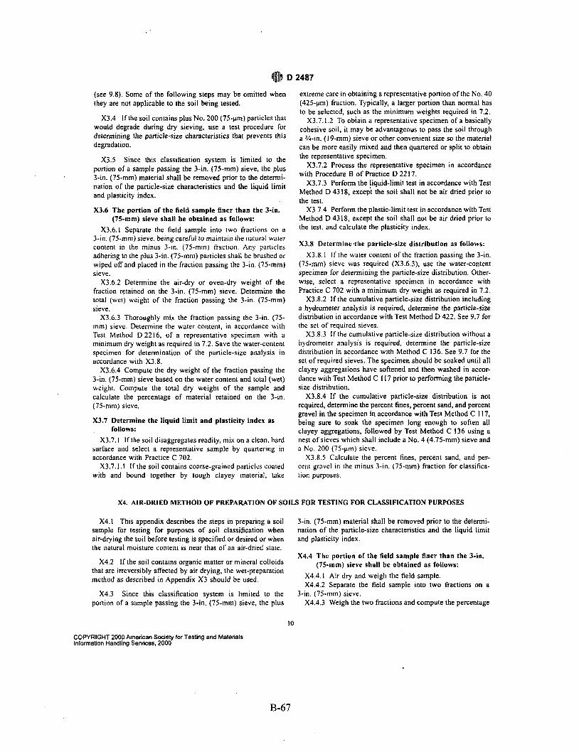
$m D 2487
(see 9.8). Some of the following steps may be omitted when they are not applicable to the soil being tested.
X3.4 If the soil contains plus No. 200 (75-pm) particles that would degrade during dry sieving, use a test procedure for determining the particle-size characteristics that prevents this degradation.
X3.5 Since this classification system is limited to the portion of a sample passing the 3-in. (75-mm) sieve, the plus 3-in. (75-mm) material shall be removed prior to the determi- nation of the particle-size characteristics and the liquid limit and plasticity index.
X3.6 The portion of the field sample finer than the 3-in. (75-mm) sieve shall be obtained as follows:
X3.6.1 Separate the field sample into two fractions on a 3-in. (75-mm) sieve. being careful to maintain the natural waier content in the minus 3-in. (75-mm) fraction. Any pariicles adhering to the plus 3-in. (75-mm) panicles shall be brushed or wiped off and placed in the fraction passing the 3-in. (75-mm) sieve.
X3.6.2 Determine the air-dry or oven-dry weight of the fraction retained on the 3-in. (75-mm) sieve. Determine the total (wet) weight of the fraction passing the 3-in. (75-mm) sieve.
X3.6.3 Thoroughly mix the fraction passing the 3-in. (75- mm) sieve. Determine the water content, in accordance with Test Method D2216, of a representative specimen with a minimum dry weight as required in 7.2. Save the water-content specimen for determination of the particle-size analysis in accordance with X3.8.
X3.6.4 Compute the dry weight of the fraction passing the 3-in. (75-mm) sieve based on the water content and total (wet) weight. Compute the total dry weight of the sample and calculate the percentage of material retained on the 3-in. (75-mm) sieve.
X3.7 Determine the liquid limit and plasticity index as follows:
X3.7.1 If the soil disaggregates readily, mix on a clean, hard surface and select a representativr sample by quanering i n accordance with Practice C 702.
X3.7.I.I I f the soil contains coarse-grained panicles coaled with and bound together by tough clayey material, lake
extreme care in obtaining a representative portion of the No. 40 (425-pm) fraction. Typically, a larger portion than normal has to be selected, such as the minimum weights required in 7.2.
X3.7. I .Z To obiain a representative specimen of a basically cohesive soil, it may be advantageous to pass the soil through a %-in. (19-mm) sieve or other convenient size so the material can be more easily mixed and then quartered or split to obtain the representative specimen.
X3.7.2 Process the representative specimen in accordance with Procedure B of Practice D 22 17.
X3.7.3 Perform the liquid-limit test in accordance with Test Method D 4318, except the soil shall not be air dried prior to the test.
X3.7.4 Perfonn the plastic-limit test in accordance with Test Method D 43 18, except the soil shall not be air dried prior to the test. and calculate the plasticity index.
X3.8 Determine .the particle-size distribution as follows: X3.8. I I f the water content of the fraction passing the 3-in.
(75-mm) sieve was required (X3.6.3), use the water-content specimen for determining the particle-size distribution. Other- wise, select a representative specimen in accordance with Practice C 702 with a minimum dry weight as required in 7.2.
X3.8.2 If the cumulative particle-size distribution including a hydrometer analysis is required, determine the panicle-size distribution in accordance with Test Method D 422. See 9.7 for the set of required sieves.
X3.8.3 I f the cumulative particle-size distribution without a hydrometer analysis is required, determine the particle-size distribution in accordance with Method C 136. See 9.7 for the set of required sieves. The specimen should be soaked until all clayey aggregations have softened and then washed in accor- dance with Test Method C 1 I7 prior to performing the panicle- size distribution.
X3.8.4 If the cumulative particle-size distribution is not required, determine the percent fines, percent sand, and percent gravel in the specimen in accordance with Test Method C 1 17, being sure to soak the specimen long enough to soften all clayey aggregations, followed by Test Method C 136 using a nest of sieves which shall include a No. 4 (4.75-mm) sieve and a No. 200 (75-pm) sieve.
X3.8.5 Calculate the percent fines, percent sand, and per- cent gravel i n the minus 3-in. (75-mm) fraction for classifica- tion purposes.
X4. AIR-DRIED METHOD OF PREPARATION OF SOILS FOR TESTING FOR CLASSIFICATION PURPOSES
X4.1 This appendix describes the steps in preparing a soil sample for testing for purposes of soil classification when air-drying the soil before testing is specified or desired or when the natural moisture content is near that of an air-dried state.
X4.2 If the soil contains organic matter or mineral colloids that are irreversibly affected by air drying, the wet-preparation method as described in Appendix X3 should be used.
Since this classification system is limited to the portion of a sample passing the 3-in. (75-rnm) sieve, the plus
X4.3
3-in. (75-mm) material shall be removed prior to the determi- nation of the particle-size characteristics and the liquid limit and plasticity index.
X4.4 The portion of the field sample finer than the 3-in. (75-rnm) sieve shall be obtained as follows:
X4.4. I Air dry and weigh the field sample. X4.4.2 Separate the field sample into two fractions on a
X4.4.3 Weigh the two fractions and compute the percentage 3-in. (75-mm) sieve.
10
COPYRIGHT 2000 American Society for Testing and Materials Information Handling Services, 2000
B-67
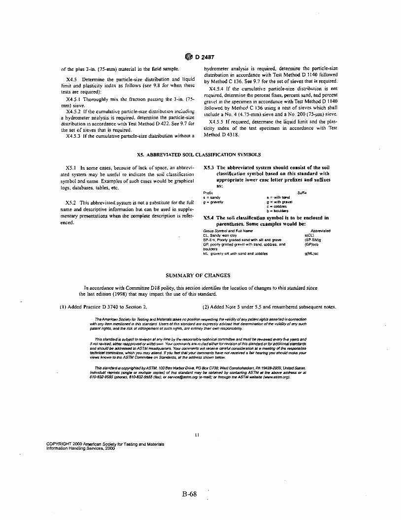
of the plus 3-in. (75-mm) material in the field sample.
Determine the particle-size distribution and liquid limit and plasticity index as follows (see 9.8 for when these tests are required):
mm) sieve. X4.5.2 If the cumulative particle-size distribution including
a hydrometer analysis is required, determine the particle-size distributioil in accordance with Test .Method D 422. See 9.7 for the set of sieves that is required.
X4.5.3 If the cumulative particle-size distribution without a
hydrometer analysis is required, determine the particle-size distribution in accordance with Test Method D 1140 followed by Method 136, See 9.7 for the set of sieves that is required,
X4.5.4 If the cumulative particle-size distribution i s not required. determine the percent fines, percent sand, and percent
followed by Method C 136 using a nest of sieves which shall include a No. 4 (4.75-mm) sieve and a No. 200 (75-pm) sieve.
x3.5.5 I f required, determine the liquid limit and the plas- ticity index of the test specimen in accordance with Test Method D 4318.
X4.5
x4.5.1 mix the fraction passing the 3-in. (75- gravel ill the specimen In accordance with Test Method D 1140
X5. ABBREVIATED SOIL CLASSIFICATION SYMBOLS
X5.1 In some cases, because of lack of space, an abbrevi- ated system may be useful to indicate the soil classification symbol and name. Examples of such cases would be graphical logs, databases, tables, etc.
X5.2 This abbreviated system is not a substitute for the full name and descriptive information but can be used in supple- mentary presentations when the complete description is refer- enced.
X5.3 The abbreviated system should consist of the soil classification symbol based on this standard with appropriate lower case letter prefixes and suffixes as:
Prefix suffix s = sandy g = gravelly
s = wilh sand g I with gravel c =cobbles b = boulders
X5.4 The soil classification symbol is to be enclosed in parentheses. Some examples would be:
Group Symbol and Full Name CL, Sandy lean clay S(CL1 SP-Sm, Pmrly graded sand with silt and gravel GP. poorly graded gravel with sand. cobbles. and boulders ML. gravelly SIN wllh sand and cobbles
Abbreviated
(SP-SM)g (GP)scb
9(WSC
SUMMARY OF CHANGES
In accordance with Committee D l 8 policy, this section identifies the location of changes to this standard since the last edition (1998) that may impact the use of this standard.
( I ) Added Practice D 3740 to Section 2. (2) Added Note 5 under 5.5 and renumbered subsequent notes.
The Amermn Swely lor Tesling and Materials lakes no pulion respecling !he validily of any paten1 nghb asserled in conneclron wth any ilem menlioned in !his standard Users of !his standard are expressly advised that delenninalion of the valdily of any such palenl nghts. and fhe nsk of infnngemenl 01 such rights, are enlirely !heir own responsiblily
This slandard is sutqecl to rewsron a1 any lime by !he responsible lechniwl wmminee and musl be reviewed every five years and !I no1 revised. eilher reapproved or wrlhdrawn Your m m e n l s are innled eifher for revision of !his standard or for additional standards and should be addressed lo ASTM Headquarters Your mmmenls will receive careful mnsideraliM a1 a meebng d the responsible lechnrcal nwnmntee. which you may attend I f you fael !ha1 your wmmenls have not received a fair hearing you should make your view known lo the ASTM Comminee on Standards, a1 !he address shown below
This standard is wpynghled by ASTM 1W Barr Harbor Omre, PO Box C700, West cooshah~en. PA 18428-2959. Unrted Slales Individual w n n l s (sngle or mullipre copies) of this standard may be obtained by mnlacling ASTM ai the above address or a1 610-832-9585 (phone). 610-832-9555 (fax). or semce@aslm org (emad), or fhmgh !he ASTM wabsile (www aslm org)
COPYRIGHT 2000 American Society for Testing and Materials Information Handling Services, 2000
B-68

8-3. REFERENCES
Rathbum, S.L., 1991, Quaternary Channels Changes and Paleojlooding Along the Big Lost River, Idaho National Engineering Laboratory, EGG-WM-9909, EG&G, Idaho, Inc., January 1991.
Barraclough, J.T. et al, 1976, “Hydrology of the Solid Waste Burial Grounds as Related to the Potential Migration of Radionuclides, Idaho National Engineering Laboratory,” USGS Open File Report 76-47 1, U.S. Geological Survey, 1976.
B-69


