84
Appendix B Truck Loading Facility - Siting and Configuration

Appendix B Truck Loading Facility - Siting and Configuration
1 COPYRIGHT 2013 BY CH2M HILL CANADA LIMITED • ALL RIGHTS RESERVED • COMPANY CONFIDENTIAL
T E C H N I C A L M E M O R A N D U M 2
Truck Loading Facility- Siting and Configuration
PREPARED FOR: City of Toronto
PREPARED BY: M. Kim Fries
Gisselly Anania
QA/QC REVIEW: Peter Burrowes
DATE: May 22, 2013
Contents Executive Summary ............................................................................................................................. 3
1. Introduction ............................................................................................................................ 14
1.1 Project Background .................................................................................................... 14
1.2 Project Objectives ....................................................................................................... 14
1.3 Project Deliverables .................................................................................................... 15
1.4 Scope of TM 2 – Truck Loading Facility Siting and Configuration ............................. 15
1.5 Reference Documents ................................................................................................ 16
1.6 Organization of Document .......................................................................................... 16
2. Review of Design Basis ........................................................................................................ 17
3. Review of Available Biosolids Storage Technologies ....................................................... 17
3.1 Dewatered Biosolids Storage Considerations ............................................................ 17
3.2 Dewatered Biosolids Storage Options ........................................................................ 19
3.3 Selection of Biosolids Storage Option ........................................................................ 25
4. Odour Control ........................................................................................................................ 26
4.1 Introduction ................................................................................................................. 26
4.2 Odour Control Technology Selection ......................................................................... 26
4.3 Odorous Air Generation Rates ................................................................................... 28
4.4 Odorous Air Treatment Design Basis ......................................................................... 30
5. Truck Loading Facility Siting Options ................................................................................. 30
5.1 Introduction ................................................................................................................. 30
5.2 Common Features ...................................................................................................... 30
TRUCK LOADING FACILITY- SITING AND CONFIGURATION
2 COPYRIGHT 2013 BY CH2M HILL CANADA LIMITED • ALL RIGHTS RESERVED • COMPANY CONFIDENTIAL
5.3 Truck Loading Facility Options – Basic Description .................................................... 33
5.4 Option 1 – Master Plan Option (New Truck Loading Facility East of Existing Biosolids
Treatment Facility) ...................................................................................................... 35
5.5 Option 2 – Modified Master Plan Option (New Dewatering and Truck Loading Facility
East of Existing Biosolids Management Building) ....................................................... 37
5.6 Option 3 - New Dewatering and Truck Loading Facility East of New Dechlorination
Building ....................................................................................................................... 39
5.7 Option 4 – New Truck Loading Facility in Area of Existing Heat Treatment Area ...... 41
6. Cost Comparison of Options ................................................................................................ 43
6.1 Capital Cost Estimates ................................................................................................ 43
6.2 Operation and Maintenance Cost Estimates .............................................................. 46
7. Non-Monetary Comparison of Options ................................................................................ 47
8. Recommended Option ........................................................................................................... 48
Appendix 1 – Option 1 Drawings
Appendix 2 – Option 1 Costs
Appendix 3 – Option 2 Drawings
Appendix 4 – Option 2 Costs
Appendix 5 – Option 3 Drawings
Appendix 6 – Option 3 Costs
Appendix 7 – Option 4 Drawings
Appendix 8 – Option 4 Costs
Appendix 9 – Summary of Life Cycle Costs

TRUCK LOADING FACILITY- SITING AND CONFIGURATION
3 COPYRIGHT 2013 BY CH2M HILL CANADA LIMITED • ALL RIGHTS RESERVED • COMPANY CONFIDENTIAL
Executive Summary
ES.1 Introduction Over the last 10 years, The City of Toronto has been working toward the development and
implementation of a Biosolids Management Strategy that meets their overall economic, environmental
and social objectives. In a continuation of this program, in 2012, The City retained CH2M HILL
Canada Limited (CH2M HILL) to prepare a conceptual design for a biosolids Truck Loading Facility
and accompanying odour control features at the Highland Creek Treatment Plant.
The project aims to achieve the following objectives:
1. Develop four conceptual layout options for the Truck Loading Facility, all of which incorporate
odour control systems. The four potential options advanced by the City early in the project for the
Truck Loading Facility include:
a. Utilize the existing Biosolids Management Facility to locate the Biosolids Truck Loading
Facility.
b. Expand the existing Biosolids Management Building to accommodate a new Biosolids Truck
Loading Facility.
c. Construct a new Biosolids Truck Loading Facility on site, and close to the existing Biosolids
Management Building.
d. Construct a new Truck Loading Facility located on the main plant, east of new Dechlorination
Building.
2. Assess the capacity requirements associated with the Biosolids Truck Loading Facility in terms of
biosolids handling capabilities as well as the needs of major ancillary systems.
3. Considering the differences in biosolids treatment requirements for beneficial use rather than
thermal reduction, assess the capacity of the existing four anaerobic digesters and associated
ancillaries (gas handling system, waste gas burners, etc) based on the updated mass balance
and the current waste activated sludge (WAS) thickening project. Identify expansion requirements
and develop alternatives, with conceptual layout plans for these alternatives.
4. Recommend a preferred conceptual design that best meets the City’s requirements for the Truck
Loading Facility and for the existing anaerobic digestion system.
This Technical Memorandum 2 will focus on the review and evaluation of a Biolsolids Truck Loading
Facility sites and potential configuration alternatives specific to those sites. For the number of
potential sites that could be considered for the location of the Truck Loading Facility, all have different
advantages and disadvantages including:
TRUCK LOADING FACILITY- SITING AND CONFIGURATION
4 COPYRIGHT 2013 BY CH2M HILL CANADA LIMITED • ALL RIGHTS RESERVED • COMPANY CONFIDENTIAL
Compatibility with the existing plant infrastructure
Operability and maintainability
Impact on the neighbouring areas due to visibility, traffic, noise, etc
Costs
The four siting options considered for a Truck Loading Facility were discussed at length between the
project team and the City. The options to be considered evolved as a result of these discussions, as
will be discussed in the document. The resulting short list of siting options all mandate differing
approaches to the configuration of the facility.
ES.2 Design Basis The new Biosolids Truck Loading Facility will be constructed to handle the projected maximum
biosolids generation rates for 2032, providing 5.5 days of storage for this material. This requirement
translates into a volumetric requirement of almost 1,200 m3.
ES.3 Review of Dewatered Biosolids Storage Technologies Biosolids storage must deal with a number of material handling issues that are specific to this type of
material, as follows:
Material Adhesion
Material Compressibility
Bridging
Material Degradation
Angle of Repose
Abrasive Characteristics
Hopper or Silo Size
Maintainability
Five generic technologies have been identified for biosolids storage, including:
Simple Centre Cone Circular Silos
Modified Centre Cone Circular Silos
Center Arms Silos
Sliding Frame Silos
V-Bottom Bins with Live Bottoms
The first option is not suitable for biosolids storage because it does not effectively deal with the
bridging issues. Of the other four technologies, all could provide suitable service for the Highland
Creek application; however, the V-bottom bins are more generally used for larger systems because
they allow for somewhat better space utilization and they do have the advantage that if one part of the
TRUCK LOADING FACILITY- SITING AND CONFIGURATION
5 COPYRIGHT 2013 BY CH2M HILL CANADA LIMITED • ALL RIGHTS RESERVED • COMPANY CONFIDENTIAL
system malfunctions, stored material can be still be removed by the remaining devices to enable
repair. For these reasons, V-bottom bins have been selected for this application.
Several options that will be considered incorporate intermediate storage, with dewatered cake
pumping used to transfer biosolids to the Truck Loading Facility. For this storage function, given its
small size and its compatibility with biosolids pumping, sliding frame silos have been selected.
In either case, it would be prudent to further test the market when making the final decision on
biosolids storage technologies.
ES.4 Odour Control Odorous air is generated when ambient air comes into contact with biosolids. This airstream needs to
be contained and treated to ensure it does not cause unacceptable impacts. Odorous air will include
the air drawn from the new process units in the Truck Loading Facility and the general exhaust air
from the truck loading area itself. In addition, any odour control system will need to manage the
odorous air streams that have historically been collected and discharged to the incinerator as
combustion air. The resulting thermal oxidation and subsequent dispersion effectively eliminates
odour from those sources; however, after the incinerator is retired the odorous air will need to be
treated in some other manner to control odours.
Various technologies are available for odour control The system selected for incorporation in this
work involves a single stage biofilter. Biofilters have been used previously by the City of Toronto and
because of their biological basis, they have definite advantages when compared to other more
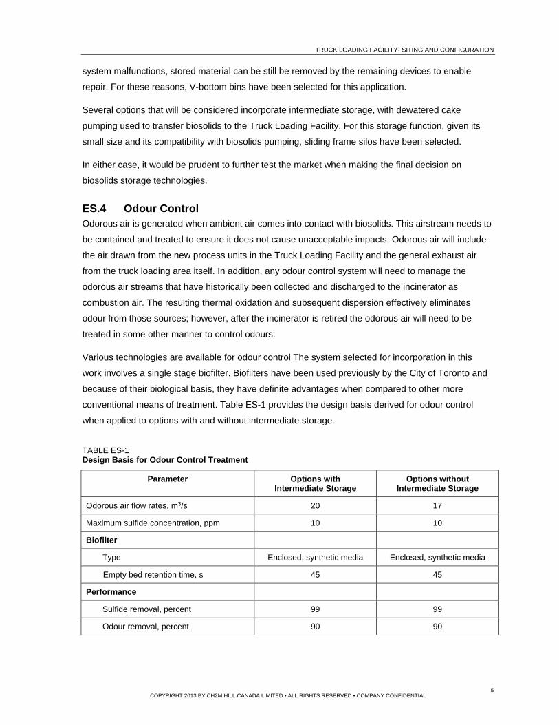
conventional means of treatment. Table ES-1 provides the design basis derived for odour control
when applied to options with and without intermediate storage.
TABLE ES-1 Design Basis for Odour Control Treatment
Parameter Options with Intermediate Storage
Options without Intermediate Storage
Odorous air flow rates, m3/s 20 17
Maximum sulfide concentration, ppm 10 10
Biofilter
Type Enclosed, synthetic media Enclosed, synthetic media
Empty bed retention time, s 45 45
Performance
Sulfide removal, percent 99 99
Odour removal, percent 90 90
TRUCK LOADING FACILITY- SITING AND CONFIGURATION
6 COPYRIGHT 2013 BY CH2M HILL CANADA LIMITED • ALL RIGHTS RESERVED • COMPANY CONFIDENTIAL
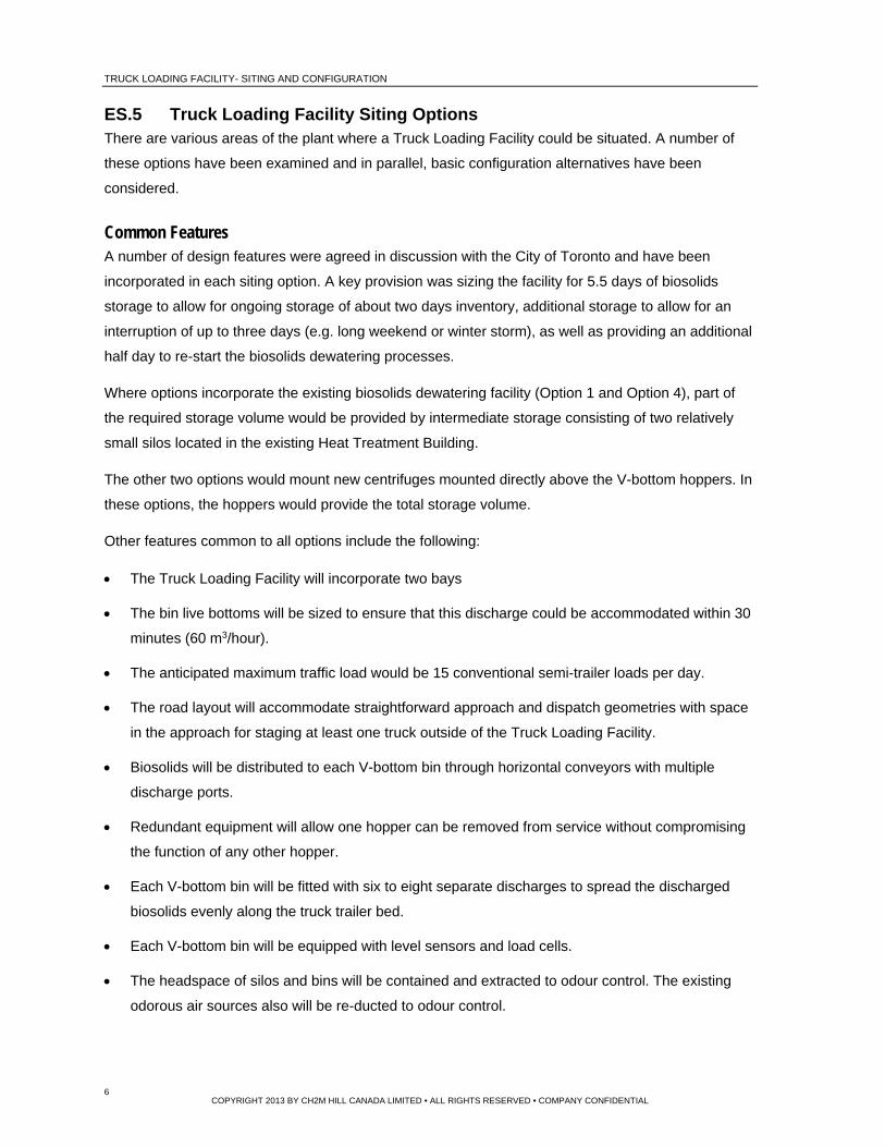
ES.5 Truck Loading Facility Siting Options There are various areas of the plant where a Truck Loading Facility could be situated. A number of
these options have been examined and in parallel, basic configuration alternatives have been
considered.
Common Features A number of design features were agreed in discussion with the City of Toronto and have been
incorporated in each siting option. A key provision was sizing the facility for 5.5 days of biosolids
storage to allow for ongoing storage of about two days inventory, additional storage to allow for an
interruption of up to three days (e.g. long weekend or winter storm), as well as providing an additional
half day to re-start the biosolids dewatering processes.
Where options incorporate the existing biosolids dewatering facility (Option 1 and Option 4), part of
the required storage volume would be provided by intermediate storage consisting of two relatively
small silos located in the existing Heat Treatment Building.
The other two options would mount new centrifuges mounted directly above the V-bottom hoppers. In
these options, the hoppers would provide the total storage volume.
Other features common to all options include the following:
The Truck Loading Facility will incorporate two bays
The bin live bottoms will be sized to ensure that this discharge could be accommodated within 30
minutes (60 m3/hour).
The anticipated maximum traffic load would be 15 conventional semi-trailer loads per day.
The road layout will accommodate straightforward approach and dispatch geometries with space
in the approach for staging at least one truck outside of the Truck Loading Facility.
Biosolids will be distributed to each V-bottom bin through horizontal conveyors with multiple
discharge ports.
Redundant equipment will allow one hopper can be removed from service without compromising
the function of any other hopper.
Each V-bottom bin will be fitted with six to eight separate discharges to spread the discharged
biosolids evenly along the truck trailer bed.
Each V-bottom bin will be equipped with level sensors and load cells.
The headspace of silos and bins will be contained and extracted to odour control. The existing
odorous air sources also will be re-ducted to odour control.

TRUCK LOADING FACILITY- SITING AND CONFIGURATION
7 COPYRIGHT 2013 BY CH2M HILL CANADA LIMITED • ALL RIGHTS RESERVED • COMPANY CONFIDENTIAL
Two weigh scales will be located below each V-bottom bin
The doors at both ends of the truck bays would be closed during loading to restrict the escape of
fugitive odorous air.
A washdown area will be incorporated in the arrangement to accommodate clean-up after truck
loading so that trucks do not exit the facility with visible evidence of splash or spillage.
Table ES-2 summarizes the key capacity requirements based on the projected 2032 biosolids
quantities and outlines the preliminary design basis for the Truck Loading Facility at the HCTP.
TABLE ES-2 Truck Loading Facility Design Basis Summary
Parameter Value
Biosolids Cake Conveyance
Biosolids cake transferring system capacity 6.0 m3/hr (average biosolids cake production rate) – 11.1 m3/hr (maximum centrifuge output capacity)
Biosolids Cake Storage
Storage capacity 5.5 days for max week biosolids cake production rate
Total storage volume (215 m3/d x 5.5 days)1 1,200 m3
Intermediate storage silo volume (150 m3 x 2 silos) 300 m3
Number of V-Bottom Bins at the Truck Loading Facility
4 (two bins per loading bay)
Dewatered biosolids cake storage capacity at V-Bottom Bins (225 m3/bin x 4 bins), with intermediate storage
900 m3
Dewatered biosolids cake storage capacity at V-Bottom Bins (300 m3/bin x 4 bins), without intermediate storage
1,200 m3
Biosolids Cake Discharging and Loading
Number of loading bays 2
Capacity of each truck 30 metric tonnes
Loading time 30 min per truck
Discharge capacity (30 metric tonnes/30 min) 60 wet tonnes/hr per loading bay
Wash-down area Integrated into the loading bays
Note: 1 The Biosolids Master Plan for HCTP (AECOM, 2011) recommended that the peak daily biosolids production
rate at the rated capacity for the HCTP was 200 m3 /d. This value is approximately 7% less than the value of 215 m3 /d recommended in this TM because different historical data were used between that study and this TM. However, the difference is considered minor.
TRUCK LOADING FACILITY- SITING AND CONFIGURATION
8 COPYRIGHT 2013 BY CH2M HILL CANADA LIMITED • ALL RIGHTS RESERVED • COMPANY CONFIDENTIAL
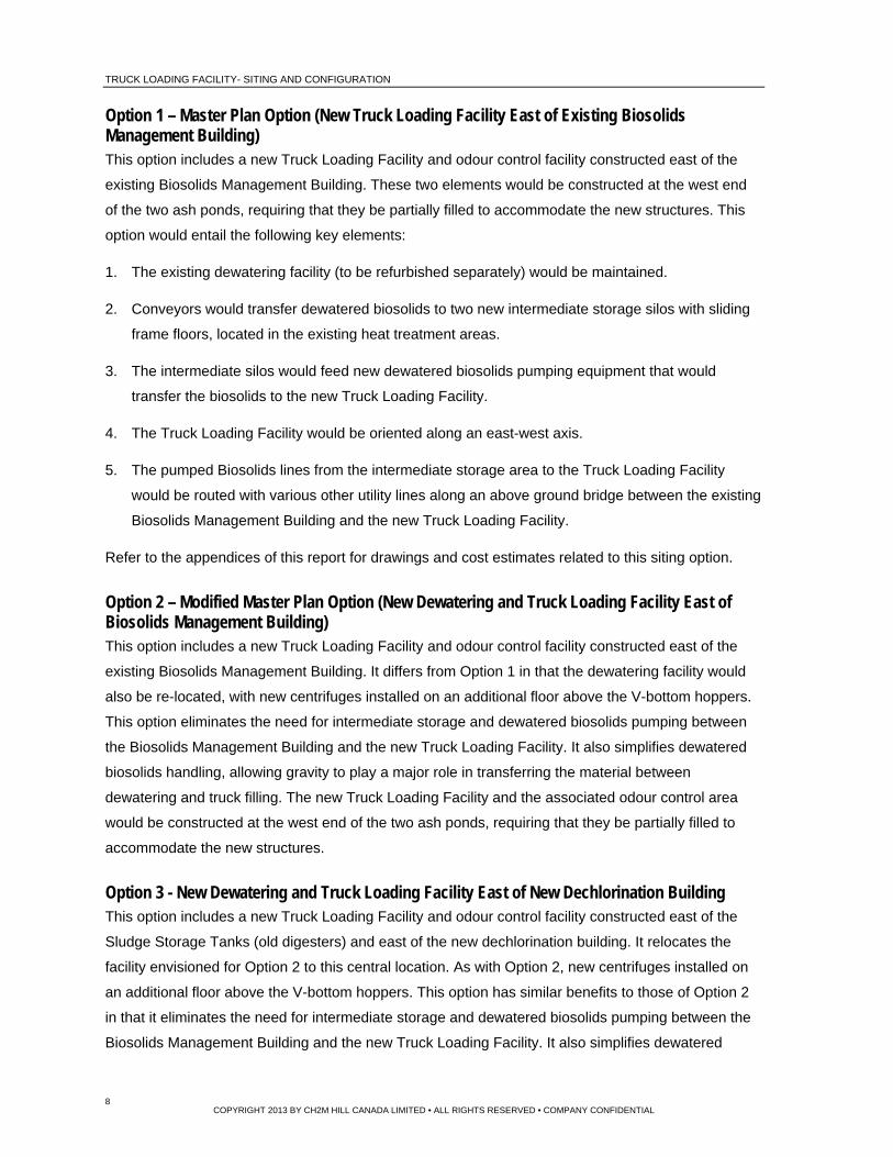
Option 1 – Master Plan Option (New Truck Loading Facility East of Existing Biosolids Management Building) This option includes a new Truck Loading Facility and odour control facility constructed east of the
existing Biosolids Management Building. These two elements would be constructed at the west end
of the two ash ponds, requiring that they be partially filled to accommodate the new structures. This
option would entail the following key elements:
1. The existing dewatering facility (to be refurbished separately) would be maintained.
2. Conveyors would transfer dewatered biosolids to two new intermediate storage silos with sliding
frame floors, located in the existing heat treatment areas.
3. The intermediate silos would feed new dewatered biosolids pumping equipment that would
transfer the biosolids to the new Truck Loading Facility.
4. The Truck Loading Facility would be oriented along an east-west axis.
5. The pumped Biosolids lines from the intermediate storage area to the Truck Loading Facility
would be routed with various other utility lines along an above ground bridge between the existing
Biosolids Management Building and the new Truck Loading Facility.
Refer to the appendices of this report for drawings and cost estimates related to this siting option.
Option 2 – Modified Master Plan Option (New Dewatering and Truck Loading Facility East of Biosolids Management Building) This option includes a new Truck Loading Facility and odour control facility constructed east of the
existing Biosolids Management Building. It differs from Option 1 in that the dewatering facility would
also be re-located, with new centrifuges installed on an additional floor above the V-bottom hoppers.
This option eliminates the need for intermediate storage and dewatered biosolids pumping between
the Biosolids Management Building and the new Truck Loading Facility. It also simplifies dewatered
biosolids handling, allowing gravity to play a major role in transferring the material between
dewatering and truck filling. The new Truck Loading Facility and the associated odour control area
would be constructed at the west end of the two ash ponds, requiring that they be partially filled to
accommodate the new structures.
Option 3 - New Dewatering and Truck Loading Facility East of New Dechlorination Building This option includes a new Truck Loading Facility and odour control facility constructed east of the
Sludge Storage Tanks (old digesters) and east of the new dechlorination building. It relocates the
facility envisioned for Option 2 to this central location. As with Option 2, new centrifuges installed on
an additional floor above the V-bottom hoppers. This option has similar benefits to those of Option 2
in that it eliminates the need for intermediate storage and dewatered biosolids pumping between the
Biosolids Management Building and the new Truck Loading Facility. It also simplifies dewatered

TRUCK LOADING FACILITY- SITING AND CONFIGURATION
9 COPYRIGHT 2013 BY CH2M HILL CANADA LIMITED • ALL RIGHTS RESERVED • COMPANY CONFIDENTIAL
biosolids handling, allowing gravity to play a major role in transferring the material between
dewatering and truck filling. The new Truck Loading Facility and the associated odour control area
would be constructed east of the existing Sludge Storage Tanks and the new dechlorination building,
adjacent to and parallel with the main plant access road.
Option 4 – New Truck Loading Facility in Area of Existing Heat Treatment Building. This option is very similar to Option 1 other than the new Truck Loading Facility would be built in the
area of the existing, retired heat treatment area. It includes a new Truck Loading Facility and odour
control facility constructed on the east side of the existing Biosolids Management Building. The
existing two ash ponds would be unaffected by the construction, other than there would be some
upgrading of the perimeter roadway to accommodate trucks circling the site.
ES.6 Cost Comparison of Options Class 4 capital cost estimates have been prepared for the four options considered for the Truck Loading
Facility. These estimates are based on vendor proposals for major equipment, unit prices for structural
portions of the work and similar elements constructed at other wastewater treatment plants, and
allowances for various components based on complexity and scope. The estimate at this point in project
development is considered to have Class 4 accuracy, or accurate to within -30 percent / +50 percent.
The detailed capital costs developed for each option are attached to this report in a series of Appendices
(Appendix 2, Appendix 4, Appendix 6, and Appendix 8). Table ES-3 summarizes these estimates.

TRUCK LOADING FACILITY- SITING AND CONFIGURATION
10 COPYRIGHT 2013 BY CH2M HILL CANADA LIMITED • ALL RIGHTS RESERVED • COMPANY CONFIDENTIAL
TABLE ES-3 Summary of Capital Cost Estimates1 (Excludes Digestion Upgrades to accommodate for Beneficial Use of Biosolids)
Description Option 12 Option 23 Option 34 Option 45
DIV 2- Building Sitework
Civil work, Demolition, Tie-ins $ 4,975,000 $ 3,175,000 $ 7,150,000 $ 9,375,000
DIV 3 and DIV 4- Concrete and Masonry
Building Structural work
$ 12,825,000 $ 17,487,000 $ 16,987,000 $ 16,825,000
DIV 11, DIV 14 and DIV 15B –Equipment, conveying systems and process mechanical
$ 17, 120,000 $ 15,940,000 $ 15,590,000 $ 16,620,000
DIV 15A- Building Mechanical
Heating, Ventilation and Air Conditioning (HVAC)
$ 2,850,000 $ 3,100,000 $ 3,100,000 $ 2,850,000
DIV 16 A-Electrical $ 4,581,000 $ 4,236,000 $ 4,236,000 $ 4,581,000
DIV 13-Instrumentation and Control
$ 3,818,000 $ 3,530,000 $ 3,530,000 $ 3,818,000
Subtotal Direct Cost6, 1 $ 46,169,000 $ 47,469,000 $ 50,593,000 $ 54,068,000
Indirect Cost (Contractor’s profit, bonds, insurance, etc)
$ 12,092,000 $ 12,433,000 $ 13,251,000 $ 14,161,000
Subtotal Direct + Indirect Cost $ 58,261,000 $ 59,901,000 $ 63,844,000 $ 68,230,000
Contingency (30%) $ 17,478,000 $ 17,970,000 $ 19,153,000 $ 20,469,000
Escalation1- 2016 dollars $ 7,377,000 $ 7,585,000 $ 8,084,000 $ 8,640,000
Total Construction Cost (Excluding Engineering and HST)
$ 83,116,000 $ 85,455,000 $ 91,081,000 $ 97,337,000
Engineering Cost (12 % of Total Construction Cost)
$ 9,974,000 $ 10,255,000 $ 10,923,000 $ 11,680,000
Total Estimated Capital Cost, Including Construction, Engineering and excluding HST
$ 93,090,000 $ 95,710,000 $ 102,011,000 $ 109,012,000
Note: 1 Estimates are shown in 2012 dollars (Direct Cost), with escalation to midpoint in construction indicated
separately (2016). It has been assumed that projects would be tendered in 2015 and constructed by 2017. Some totals may be appear incorrect; when compared to cost presented in Appendices 2,4,6, 8; due to rounding errors.
2 Option 1 – Master Plan Option (New Truck Loading Facility east of the existing Biosolids Management Building). 3 Option 2 – Modified Master Plan Option (New Truck Loading Facility and dewatering facility east of the existing
Biosolids Management Building). 4 Option 3 – New Truck Loading Facility and dewatering facility at a central location, east of the new
Dechlorination Building 5 Option 4 – New Truck Loading Facility within the existing Heat Treatment area. 6 Direct Cost includes DIVs-2, 3, 4, 11, 14, 15 A and B, 13, 16A. Details are presented in Appendices 2,4,6, 8

TRUCK LOADING FACILITY- SITING AND CONFIGURATION
11 COPYRIGHT 2013 BY CH2M HILL CANADA LIMITED • ALL RIGHTS RESERVED • COMPANY CONFIDENTIAL
Estimates of the majority of the operation and maintenance costs have been derived, focusing on the
areas where there would be some differentiation. Operation and maintenance cost estimates for the
four options, developed on this basis, are summarized in Table ES-4.
TABLE ES-4 Summary of Operation and Maintenance Cost Estimates1
Description Option 1 Option 2 Option 3 Option 4
Power Consumption $477,000 $402,000 $402,000 $477,000
Labour $1,147,000 $983,000 $983,000 $1,147,000
Maintenance – Mechanical Equipment, Electrical, SCADA and I&C
$597,000 $562,000 $562,000 $597,000
Polymer Consumption, Natural Gas
$578,000 $631,000 $474,000 $578,000
Total Estimated O&M Cost, Excluding HST
$ 2,800,000 $ 2,579,000 $ 2,421,000 $ 2,800,000
Note: 1 Some totals may be appear incorrect due to rounding errors.
The life cycle costs of the four options also have been derived based on capital expenditures being
expended between 2013 and 2017, with operation extending from 2017 to 2035. These life cycle
costs have not included HST costs, and are based on an escalation rate of 3 percent and a borrowing
rate of 6 percent. These life cycle costs are summarized in Table ES-5.
TABLE ES-5 Summary of Life Cycle Cost Estimates (Excluding Digestion Upgrades to Accommodate for Beneficial Use of Biosolids)
Description Option 12 Option 23 Option 34 Option 45
Capital Costs $ 93,090,000 $ 95,710,000 $ 102,011,000 $ 109,012,000
O&M Costs $ 2,800,000 $ 2,579,000 $ 2,421,000 $ 2,800,000
Life Cycle Costs $ 128,760,000 $ 128,180,000 $ 132,021,000 $ 144,066,000
Note: 1 Some totals may be appear incorrect due to rounding errors. 2 Option 1 – Master Plan Option (New Truck Loading Facility east of the existing Biosolids Management Building). 3 Option 2 – Modified Master Plan Option (New Truck Loading Facility and dewatering facility east of the existing
Biosolids Management Building). 4 Option 3 – New Truck Loading Facility and dewatering facility at a central location, east of the new dechlorination
Building
5 Option 4 – New Truck Loading Facility within the existing Heat Treatment area.
The estimated life cycle costs for Options 1 and Option 2 are considered roughly equivalent. At the
accuracy of the estimates used to develop these life cycle costs, the life cycle costs for Option 1 and

TRUCK LOADING FACILITY- SITING AND CONFIGURATION
12 COPYRIGHT 2013 BY CH2M HILL CANADA LIMITED • ALL RIGHTS RESERVED • COMPANY CONFIDENTIAL
Option 2 do not provide sufficient differentiation to select between them. The life cycle costs
associated with Option 3 and Option 4 is 4 to 10 percent higher than the other two options. This
differential is sufficient to conclude that Option 3 and Option 4 would exhibit higher costs than Option
1 and Option 2.
ES-7 Non-Monetary Comparison of Options Various non-monetary categories have been identified that differentiate between the various options.
The following paragraphs summarize those considerations.
Visual Impact Option 1 and Option 2 have more visual impact than the other two options. Option 3 involves a building as high as that in Option 2, but moves it to the interior of the site where it would be less evident from the surrounding properties. Option 4 utilizes the shell of the existing Heat Treatment Building to house the Truck Loading Facility, so there would be minimal change to the visual impact of the site.
Truck Traffic Truck traffic to and from the site will be the same for any option. Truck traffic through the site is less likely to cause any issues with operations for Option 1, Option 2, and Option 4. In Option 3, the truck traffic could interfere with normal plant operations because the trucks would be routed through the main plant site.
Truck Circulation Through the Site
In all cases, existing roads will need to be widened and the corners provided with larger radii to facilitate truck movement. Option 3 requires a greater amount of work.
Operations Impact during Construction
Option 3 structure constructions and process work would have the least impact on existing operations – most of the work could be completed off line. However, the site is within the existing main plant area so there would be some interference due to construction traffic. The other options require some work in the existing Biosolids Management Building.
Operations Access Option 3 offers the best operator access to the facility because it is located within the existing plant area and could be integrated into the plant tunnel system. Option 4 is also relatively accessible to operations staff.
Power Requirements Option 1, Option 2, and Option 4 could all be served from the existing feed to the Biosolids Management Building. Option 3 would require a new 5 kV feed from the plant substation.
Plant Security Option 3 has some security concerns because private trucks would enter and circulate through the main plant site.
Odour Potential Option 3 does have some minor advantage because the odour sources would be moved further from the plant boundary.
ES.8 Recommended Option Capital cost and operation and maintenance (O&M) cost estimates were prepared to allow
comparison of these four options. Option 1 and Option 2 were almost equal and enjoyed a capital

TRUCK LOADING FACILITY- SITING AND CONFIGURATION
13 COPYRIGHT 2013 BY CH2M HILL CANADA LIMITED • ALL RIGHTS RESERVED • COMPANY CONFIDENTIAL
cost advantage over Option 3 and Option 4, even when considering long term O&M costs. The
following table outlines the relative merits of the two options.
Option 1 – Master Plan Option Option 2 – Modified Master Plan Option
Building is lower (20 metres versus 26
metres tall)
Does not require relocation of dewatering
equipment
Construction would likely be completed in
slightly less time
Eliminates the need for intermediate handling
of dewatered biosolids – intermediate
storage and pumping
Consolidates dewatering in the same
operating area as the truck loading facility
Minimizes work needed in existing Heat
Treatment Area
Almost all of the infrastructure needed for
digested biosolids management is located in
one facility
Given the almost equal capital costs and the similar operational costs, there is no economic
difference between Option 1 or Option 2. Further, both options have advantages but there are no
compelling non-monetary reasons to select one of these two options. For these reasons, it is
recommended that both Options be advanced to the next stage of project development for further
assessment. Details of the cost estimates for the two options are included in Appendix 2 and 4,
attached to this Technical Memorandum.

TRUCK LOADING FACILITY- SITING AND CONFIGURATION
14 COPYRIGHT 2013 BY CH2M HILL CANADA LIMITED • ALL RIGHTS RESERVED • COMPANY CONFIDENTIAL
1. Introduction
1.1 Project Background
Over the last 10 years, The City of Toronto has been working toward the development and
implementation of a Biosolids Management Strategy that meets their overall economic, environmental
and social objectives. Key milestones during this period include the following:
Biosolids and Residuals Master Plan (BRMP), 2002. The City initiated this project to assess
options and determine a direction for the future management of biosolids and water residuals
generated by the City’s water and wastewater treatment plants to the year 2025. This report was
released for public comment in 2004.
BRMP Peer Review, 2005. The results of the BRMP were subjected to a peer review, specifically
to assess the decision making model and methodology.
BRMP Update, 2008. The BRMP was updated to incorporate the recommendations of the peer
review and to revise projected quantities and quality to reflect trends since the commencement of
the Biosolids and Residuals Master Plan. Water treatment residuals were dropped from this work;
hence, the project became known as the Biosolids Master Plan (BMP). The BMP was completed
in draft and issued for public review in 2009. The recommended alternative for the HCTP
remained thermal reduction.
Council Directive, 2010. The Council did not approve the recommended thermal reduction
alternative for HCTP, directing City staff to implement a beneficial use biosolids management
strategy for HCTP, with landfilling as a contingent option.
Staff Report, 2011. A report was forwarded to Council in 2011 outlining the findings of the BMP
for HCTP and outlining the implications of proceeding with either fluidized bed incineration
(thermal reduction technology) or a truck loading facility as needed for a beneficial use program.
Council voted to proceed with the biosolids Truck Loading Facility.
In 2012, The City retained CH2M HILL Canada Limited (CH2M HILL) to prepare a conceptual design
for a biosolids Truck Loading Facility and accompanying odour control features at the Highland Creek
Treatment Plant.
1.2 Project Objectives
The project aims to achieve the following objectives:
1. Develop four conceptual layout options for the Truck Loading Facility, all of which incorporate
odour control systems. The four potential options advanced by the City early in the project for the
Truck Loading Facility include:

TRUCK LOADING FACILITY- SITING AND CONFIGURATION
15 COPYRIGHT 2013 BY CH2M HILL CANADA LIMITED • ALL RIGHTS RESERVED • COMPANY CONFIDENTIAL
a. Utilize the existing Biosolids Management Building to locate the Truck Loading Facility.
b. Expand the existing Biosolids Management Building to accommodate a new Truck Loading
Facility.
c. Construct a new Truck Loading Facility on site, and close to the existing Biosolids
Management Building.
d. Construct a new Truck Loading Facility on site and dewatering facility at a central location,
east of the new Dechlorination Building.
2. Assess the capacity requirements associated with the Truck Loading Facility in terms of biosolids
handling capabilities as well as the needs of major ancillary systems.
3. Considering the differences in biosolids treatment requirements for beneficial use rather than
thermal reduction, assess the capacity of the existing four anaerobic digesters and associated
ancillaries (gas handling system, waste gas burners, etc) based on the updated mass balance
and the current waste activated sludge (WAS) thickening project. Identify expansion requirements
and develop alternatives, with conceptual layout plans for these alternatives.
4. Recommend a preferred conceptual design that best meets the City’s requirements for the Truck
Loading Facility and for the existing anaerobic digestion system.
1.3 Project Deliverables
The project work has been segregated into a series of logical steps that allows review of progress as
the project team arrives at specific milestones where major decisions are finalized. The deliverables
associated with these work elements are as follows:
Technical Memorandum (TM) 1: Assessment of Capacity Requirements
TM 2: Truck Loading Facility Siting and Configuration
TM 3: Digester and Waste Gas Burner Capacity Assessment
These Technical Memoranda will be compiled and attached to the final Truck Loading Facility
Conceptual Design Report. This Technical Memorandum 2 will also include the evaluation of options
for silos/hoppers, odour control requirements and alternatives, and logistical demands of the
recommended Truck Loading Facility.
1.4 Scope of TM 2 – Truck Loading Facility Siting and Configuration
As noted in Subsection 1.2, there are a number of potential sites that could be considered for the location
of the Biosolids Truck Loading Facility. All have different advantages and disadvantages including:
Compatibility with the existing plant infrastructure
TRUCK LOADING FACILITY- SITING AND CONFIGURATION
16 COPYRIGHT 2013 BY CH2M HILL CANADA LIMITED • ALL RIGHTS RESERVED • COMPANY CONFIDENTIAL
Operability and maintainability
Impact on the neighbouring areas due to visibility, traffic, noise, etc
Costs
The original three siting options considered for a Truck Loading Facility were discussed at length
between the project team and the City. The options to be considered evolved as a result of these
discussions. The resulting short list of siting options all mandate differing approaches to the
configuration of the facility.
This technical memorandum outlines the development of the siting options to be considered,
describes the basic configuration developed for each of these options, summarizes the cost estimates
derived for the selected siting options, and outlines the qualitative advantages and disadvantages of
each. As a result of this analysis, the preferred siting option will be identified.
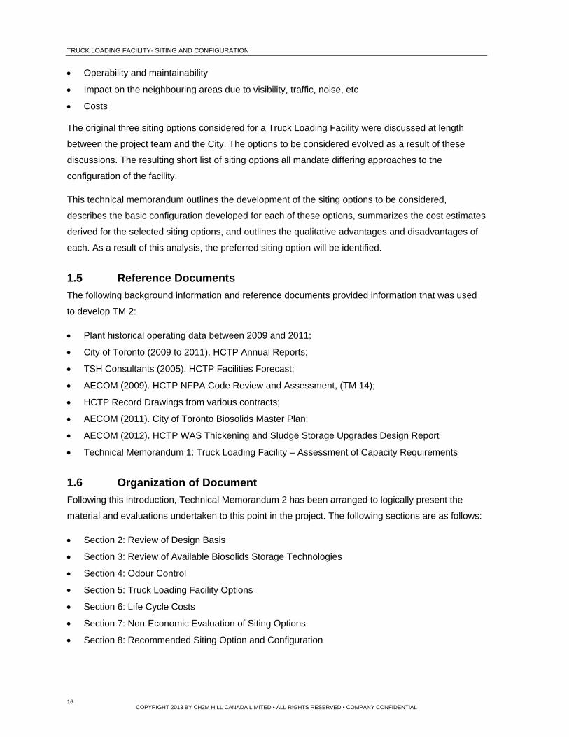
1.5 Reference Documents
The following background information and reference documents provided information that was used
to develop TM 2:
Plant historical operating data between 2009 and 2011;
City of Toronto (2009 to 2011). HCTP Annual Reports;
TSH Consultants (2005). HCTP Facilities Forecast;
AECOM (2009). HCTP NFPA Code Review and Assessment, (TM 14);
HCTP Record Drawings from various contracts;
AECOM (2011). City of Toronto Biosolids Master Plan;
AECOM (2012). HCTP WAS Thickening and Sludge Storage Upgrades Design Report
Technical Memorandum 1: Truck Loading Facility – Assessment of Capacity Requirements
1.6 Organization of Document
Following this introduction, Technical Memorandum 2 has been arranged to logically present the
material and evaluations undertaken to this point in the project. The following sections are as follows:
Section 2: Review of Design Basis
Section 3: Review of Available Biosolids Storage Technologies
Section 4: Odour Control
Section 5: Truck Loading Facility Options
Section 6: Life Cycle Costs
Section 7: Non-Economic Evaluation of Siting Options
Section 8: Recommended Siting Option and Configuration
TRUCK LOADING FACILITY- SITING AND CONFIGURATION
17 COPYRIGHT 2013 BY CH2M HILL CANADA LIMITED • ALL RIGHTS RESERVED • COMPANY CONFIDENTIAL
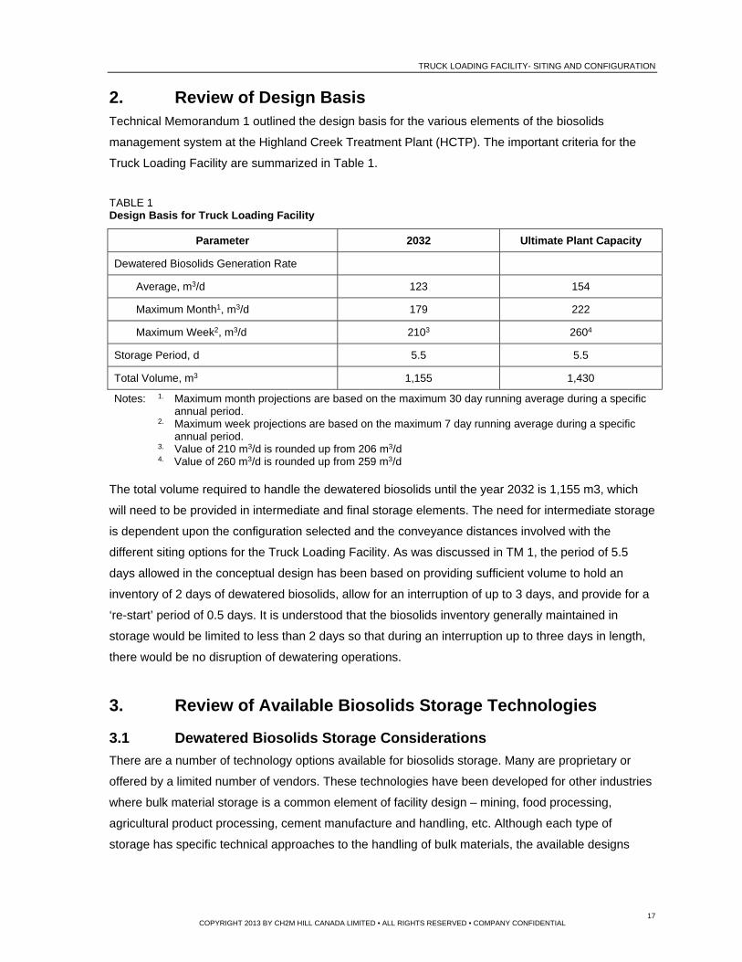
2. Review of Design Basis Technical Memorandum 1 outlined the design basis for the various elements of the biosolids
management system at the Highland Creek Treatment Plant (HCTP). The important criteria for the
Truck Loading Facility are summarized in Table 1.
TABLE 1 Design Basis for Truck Loading Facility
Parameter 2032 Ultimate Plant Capacity
Dewatered Biosolids Generation Rate
Average, m3/d 123 154
Maximum Month1, m3/d 179 222
Maximum Week2, m3/d 2103 2604
Storage Period, d 5.5 5.5
Total Volume, m3 1,155 1,430
Notes: 1. Maximum month projections are based on the maximum 30 day running average during a specific annual period.
2. Maximum week projections are based on the maximum 7 day running average during a specific annual period.
3. Value of 210 m3/d is rounded up from 206 m3/d 4. Value of 260 m3/d is rounded up from 259 m3/d
The total volume required to handle the dewatered biosolids until the year 2032 is 1,155 m3, which
will need to be provided in intermediate and final storage elements. The need for intermediate storage
is dependent upon the configuration selected and the conveyance distances involved with the
different siting options for the Truck Loading Facility. As was discussed in TM 1, the period of 5.5
days allowed in the conceptual design has been based on providing sufficient volume to hold an
inventory of 2 days of dewatered biosolids, allow for an interruption of up to 3 days, and provide for a
‘re-start’ period of 0.5 days. It is understood that the biosolids inventory generally maintained in
storage would be limited to less than 2 days so that during an interruption up to three days in length,
there would be no disruption of dewatering operations.
3. Review of Available Biosolids Storage Technologies
3.1 Dewatered Biosolids Storage Considerations
There are a number of technology options available for biosolids storage. Many are proprietary or
offered by a limited number of vendors. These technologies have been developed for other industries
where bulk material storage is a common element of facility design – mining, food processing,
agricultural product processing, cement manufacture and handling, etc. Although each type of
storage has specific technical approaches to the handling of bulk materials, the available designs

TRUCK LOADING FACILITY- SITING AND CONFIGURATION
18 COPYRIGHT 2013 BY CH2M HILL CANADA LIMITED • ALL RIGHTS RESERVED • COMPANY CONFIDENTIAL
have evolved to address specific product handling issues. The key handling issues specific to
dewatered biosolids storage include the following:
Material Adhesion: Dewatered biosolids adhere to the walls of storage containers. Vertical walls
or walls with negative slopes are best, but dictate more costly biosolids discharge mechanisms
that are able to ‘sweep’ the floor of the vessel.
Material Compressibility: Dewatered biosolids are generally discharged from centrifuges in
fairly granular form and tend to stack with relatively high porosity. However when the material is
placed under pressure, the particles deform to fill the voids and transform into a thick paste-like
mixture. During conveyance and storage, this transformation leads to issues. In pumped systems,
the paste experiences extremely high headlosses (90 to 135 kPa per metre). In systems that use
conveyors, the material compresses into corners and is difficult to dislodge. Dewatered biosolids
left in silos and hoppers will compress under its own weight and will ultimately become difficult to
remove.
Bridging: Dewatered biosolids can form a ‘bridge’ over a removal device, especially where
sloped walls converge on an opening and an arch of compressed material forms that is
sufficiently strong to support the material above. As with adhesion, the best solution to this issue
is to use vertical walls to the degree possible and to use conveyance devices that do not strictly
depend on gravity for feed to the device. Vibrators or similar elements that are often used for dry,
granular products to prevent bridging are of little use in the handling of biosolids because they
can actually enhance compaction and exacerbate bridging.
Material Degradation: Anaerobically digested biosolids remain biologically reactive even after
dewatering. Although the majority of biological degradation occurs in the anaerobic reactors, the
reactions will continue to generate the normal end products – carbon dioxide (CO2) and water
(H2O). Some methane (CH4), volatile sulphur compounds (H2S and mercaptans), and volatile
amino compounds (NH3, amino acids) can be emitted. These end products contribute to odours
and corrosion. Corrosion is of most concern in the selection of biosolids storage technologies.
Corners where product is able to collect without being removed during normal operation are most
susceptible. The anaerobic environment that occurs below these accumulations generates
sulfides that can contribute to ‘microbiologically influenced corrosion (MIC)’. These concerns lead
to the selection of storage technologies that inherently limit the potential for solids accumulations.
Angle of Repose: Due to the structure and adhesive characteristics of dewatered biosolids, they
tend to have a steep angle of repose (angle from the horizontal at which a material will remain
without erosion of the slope). This characteristic limits the ‘filling efficiency’ (proportion of
available volume that is generally occupied by material) of silos or hoppers, especially when
single discharge points are provided over large areas. To improve filling efficiency, multiple filling

TRUCK LOADING FACILITY- SITING AND CONFIGURATION
19 COPYRIGHT 2013 BY CH2M HILL CANADA LIMITED • ALL RIGHTS RESERVED • COMPANY CONFIDENTIAL
points, leveling conveyors or a combination of the two are generally incorporated in designs to
better utilize the available volume.
Abrasive Characteristics: Digested and dewatered biosolids contains a significant amount of
grit and other abrasive material. Storage and conveyance elements need to be selected with slow
moving parts and adequate sacrificial material to provide long service life.
Size: The maximum size for silos or hoppers is often dictated by transportation limitations and the
desire to minimize site assembly to reduce costs. The maximum dimension for components that
are hauled by truck is generally 3.3 metres by 3.3 metres by 12 m long. Within these dimensions,
silos/hoppers can be transported by truck to a site, albeit as a “Wide Load”. When the dimensions
of the structure exceed these limits, site assembly is necessary.
Maintainability: Regardless of a device’s rugged construction, a time will occur when mechanical
wear leads to its malfunction during operation. Repair may require the removal of any biosolids
inventory in storage. Designs that accommodate that removal with minimal other manual labour
and within a tight time frame are favoured.
3.2 Dewatered Biosolids Storage Options
There are a number of technologies potentially able to maintain functionality given the above
difficulties and constraints. The more common of these options are discussed in the following
paragraphs, starting with the option most commonly used for dry bulk material handling.
Simple Centre Cone Circular Silos: In this type of silo, solids are introduced to the top of the
silo and move downward under the influence of gravity. The bottom section is a cone or truncated
pyramid, converging to a single discharge point at the centre of the silo. The advantages and
disadvantages of this arrangement are as follows:
Advantages
Simplicity due to the limited number of moving parts
Mechanical maintenance within the silo is not necessary
Relatively low cost
Disadvantages
Relatively high cone angles must be used to reduce the potential for bridging.
It is difficult to control the discharge rate.
The filling efficiency is moderately limited without providing a leveling device or multiple feed points.
To provide the volume required at HCTP, either a very large number of silos would be needed, they would be extremely tall, or they would have to be of a diameter that would mandate significant field assembly. A 3.3 metre diameter silo that is 12 metre high would have an operating volume of about 70 m3, with an assumed filling efficiency of 85 percent.
TRUCK LOADING FACILITY- SITING AND CONFIGURATION
20 COPYRIGHT 2013 BY CH2M HILL CANADA LIMITED • ALL RIGHTS RESERVED • COMPANY CONFIDENTIAL
Space is not used effectively due to high cone angles and circular shape. A cone with a side slope angle of 60° has 33 percent of the volume of a cylindrical section of the same height and diameter.
Modified Centre Cone Circular Silos: This type of silo is similar to the simple circular option, but
fitted with some mechanical device in the bottom cone that prevents bridging. The device may
include a rotating full width auger/conveyor, a rotating sweep arm, or similar. The slope of the
bottom cone can be reduced as the device not only prevents bridging but acts to draw the stored
biosolids to a centre discharge point. Further, the rotational speed can be manipulated to obtain
some control over discharge rates. The advantages and disadvantages of these types of silos are
as follows:
Advantages
Relatively simple due to the low number of moving parts.
Discharge rates can be controlled and are relatively high (low filling times).
Reasonable cost.
Disadvantages
Moderately high cone angles must be used to reduce the potential for bridging.
Mechanical maintenance within the hopper may be necessary.
Large storage volumes arranged to suit parallel loading bays generally mandate a number of silos (eight or more would likely be required for the HCTP), with a commensurate increase in operating elements.
To provide the volume required at HCTP, either a very large number of silos would be needed, they would be extremely tall, or they would have to be of a diameter that would mandate significant field assembly. A 3.3 metre diameter silo that is 12 metre high would have an operating volume of about 70 m3, with an assumed filling efficiency of 85 percent.
The filling efficiency is moderately limited without providing a leveling device or multiple feed points.
Space is not used as effectively as possible due to cone angles and circular shape.
Center Arms Silos: This type of silo has a near flat floor and uses a center driven arm to sweep
the material, generally into a transverse screw conveyor. The advantages and disadvantages of
these types of silos are as follows:
Advantages
Relatively simple due to the low number of moving parts.
Discharge rates can be controlled and are relatively high (low filling times for haul vehicles).
Low cone angles lead to better utilization of space, although circular shape is less effective than rectangular shape.
Reasonable cost.

TRUCK LOADING FACILITY- SITING AND CONFIGURATION
21 COPYRIGHT 2013 BY CH2M HILL CANADA LIMITED • ALL RIGHTS RESERVED • COMPANY CONFIDENTIAL
Disadvantages
Mechanical maintenance within the hopper may be necessary. The drive centered under the middle of the silo is difficult to access for maintenance, and like the center-cone silos, a single silo discharge mechanism is provided, so it would be difficult to empty the silo if the discharge mechanism malfunctions.
Large storage volumes arranged to suit parallel loading bays generally mandate a number of silos (eight would be minimum likely for the HCTP), with a commensurate increase in operating elements.
To provide the volume required at HCTP, either a very large number of silos would be needed, they would be extremely tall, or they would have to be of a diameter that would mandate significant field assembly. A 3.3 metre diameter silo that is 12 metre high would have an operating volume of about 82.5 m3, with an assumed filling efficiency of 85 percent.
The filling efficiency is moderately limited without providing a leveling device or multiple feed points.
Sliding Frame Silos: This type of silos has a flat floor and includes a single elliptical sliding
frame driven by reciprocating hydraulic cylinders to sweep the bottom surface of the silo. The
advantages and disadvantages of these types of silos are as follows:
Advantages
Relatively simple due to the low number of moving parts. The sliding frame is relatively robust and should require minimal maintenance.
Bridging is very unlikely to occur given the vertical walls,
Discharge rates can be controlled and are relatively high (low filling times for haul vehicles).
Flat floors lead to better utilization of space, although circular shape is less effective than rectangular shape.
Reasonable cost.
Disadvantages
Mechanical maintenance within the hopper may be necessary, although the drive, external to the side of the silo, is readily accessible.
Large storage volumes arranged to suit parallel loading bays generally mandate a number of silos (eight or more would likely be required for the HCTP), with a commensurate increase in operating elements.
To provide the volume required at HCTP, either a very large number of silos would be needed, they would be extremely tall, or they would have to be of a diameter that would mandate significant field assembly. A 3.3 metre diameter silo that is 12 metre high would have an operating volume of about 87.5 m3, with an assumed filling efficiency of 85 percent.
The filling efficiency is moderately limited without providing a leveling device or multiple feed points.
V-Bottom Bins with Live Bottoms: This type of biosolids cake storage system utilizes
rectangular or square silos with live bottom arrangements (parallel screw conveyors with motors
and gear boxes) to allow the sloped portion of the bin to be minimized, the feed rates to be
controlled and to minimize the potential for bridging. The advantages and disadvantages of these
types of hoppers are as follows:

TRUCK LOADING FACILITY- SITING AND CONFIGURATION
22 COPYRIGHT 2013 BY CH2M HILL CANADA LIMITED • ALL RIGHTS RESERVED • COMPANY CONFIDENTIAL
Advantages
Live bottom conveyors are relatively simple and robust.
Bridging is unlikely to occur as long as the walls of the hopper section are steep (>60°),
Discharge rates can be controlled and are relatively high (low filling times for haul vehicles).
Flat floors lead to better utilization of space, although circular shape is less effective than rectangular shape. One V-Bottom Bin that is 3.3 metres wide, 3.3 metres tall, and 12 metres long would hold approximately 87.6 m3 at a filling efficiency of 85 percent. Adding a second straight walled element to the top of the unit would increase the volume by 111 m3 at a filling efficiency of 85 percent.
Reasonable cost.
Disadvantages
Mechanical maintenance within the hopper may be necessary, although the drive, external to the side of the silo, is readily accessible.
The filling efficiency is moderately limited without providing a leveling device or multiple feed points.
Schematic representations of the more commonly used silo types used for biosolids storage are
presented in Figure 1. Simple centre cone silos are not represented. These silos are too prone to
bridging to be effective for large biosolids applications. Typical appurtenances used up- and
downstream of the four remaining types of silos, as well as examples of each, are described in Table 2.

TRUCK LOADING FACILITY- SITING AND CONFIGURATION
23 COPYRIGHT 2013 BY CH2M HILL CANADA LIMITED • ALL RIGHTS RESERVED • COMPANY CONFIDENTIAL
Modified Center Cone Silo
Center Arm Silo
Sliding Frame Silo V‐Bottom Bins
FIGURE 1 Schematic Illustration of Four Biosolids Storage Technologies

TRUCK LOADING FACILITY- SITING AND CONFIGURATION
24 TM2 FINALV2.DOCX COPYRIGHT 2013 BY CH2M HILL CANADA LIMITED • ALL RIGHTS RESERVED • COMPANY CONFIDENTIAL
TABLE 2 Typical Features, Appurtenances and Plant References for Four Silo Types
Technology Features Typical Upstream and Downstream Appurtenances Plant Reference
Simple Center Cone Silos
These hoppers are generally of relatively small diameter, although large diameter versions are available. Biosolids are transferred by gravity throughout and to resist bridging, the wall slopes of the bottom cone are very high (greater than 60 degrees), sloping to a central discharge gate. Different bin agitators or vibrating discharge systems can be used to further prevent bridging.
Biosolids pumps or biosolids conveyors are used to convey cake to the top of circular silos. The discharge through a single gate located at the bottom.
75th Street WWTF, Boulder Colorado
Centrifuged biosolids is pumped using progressive cavity pumps to one of three rectangular silos. Distribution to each silo is controlled by a pinch valve on the feed lateral and started/shutdown according to the silo weight as measured by a series of load cells. Each silo discharges from a single point (proprietary system – Diamond Gate from RDP), with the gate controlled to discharge a preset mass.
Center Arms Silos The hopper floor is slightly sloped toward the center and a mechanism rotates just above floor level to move the biosolids to a central conveyor or pump feed point. The rotating arm can be fabricated with ‘scrapers’ or a rotating screw conveyor may be used, either option providing the impetus for the biosolids to be transported to the center discharge point. One option uses hydraulically driven arms that extend into the cake and then retract cyclically to disrupt any bridging that might occur.
Biosolids pumps or biosolids conveyors are used to convey cake to circular silos. Although circular, these silos can be quite large and so it is common that a number of feed points are provided on the roof to distribute the biosolids across the hopper area. Optionally, a bin leveler can be employed, where a rotating rake arm is used to distribute the biosolids across the silo area as the solids build to that level. These silos discharge through one or two floor openings or through a transverse screw conveyor. For applications where the discharge is near the centre (off centre is required since the rotating mechanism is in the centre of the silo).
Solids Dewatering Facility, Clark County Water Reclamation District, Las Vegas, Nevada
Eight centrifuges are mounted above four bins. The centrifuges discharge into a series of conveyors that distribute the dewatered biosolids among the active bins. Each bin is fitted with bin levelers and an inverted bin discharger cone. The cone has arms, which rotate through the stored material both disrupting bridging and transfering the cake to the discharge point.
Sliding Frame Silos Generally, these hoppers are circular (rectangular hoppers with this unloading system are called push floor silos). The hopper floor is flat and an eliptical frame slides from one side to another transferring biosolids cake to a depressed central screw conveyor that withdraws the material to truck loading or other conveyance devices (other conveyors or dewatered biosolids pumps). Because these silos are circular, leveling conveyors are generally not required or used but relatively good filling efficiency is still achieved. The vertical sidewall design optimizes the space (nothing lost for a conical bottom section) and bridging potential is minimized.
Biosolids pumps or biosolids conveyors are used to convey cake to these silos. These hoppers are usually smaller and do not use leveling devices. However, for larger units it is common to employ leveling conveyors or multiple discharge points into the silo to assure good filling efficiency. The discharge from the silo exits to one side through a bottom full width conveyor. This arrangement simplifies structural arrangements but is less compatible with truck loading configurations. This type of silo works very well for intermediate storage where dewatered biosolids are discharged from dewatering devices into the silo and then pumped from that silo to downstream bulk storage or other biosolids processing facilities.
Lakeside WWTP, Mississauga, Ontario
A number of sliding frame silos have been installed to receive the biosolids trucked from the Clarkson WWTP to the Lakeside plant and to provide buffer storage prior to incineration. The truck unloading silos discharge through a bottom conveyor to a biosolids cake pump that feeds material to the incinerator feed biosolids hoppers.
V-Bottom Bins Generally, these hoppers are long and relatively narrow. The height is governed by the volumetric storage requirements. Additional sections can be added to increase the height and volume of the hopper. Biosolids cake is distributed along the length either through a pressurized discharge box with multiple pipes to different zones or through screw conveyors with multiple discharge points. Leveling conveyors are placed in larger hoppers to further distribute the loaded biosolids along the length of the hopper. Leveling conveyors also tend to break up large agglomerations of biosolids that can cause issues. Typically, these hoppers are provided with live bottom systems (two to four parallel conveyors) that transfer biosolids to multiple discharge points and minimize bridging potential.
Biosolids pumps or biosolids conveyors are used to convey cake to hoppers. It is common to size the hopper to suit the dimensions of a truck box and allow for three or four discharge points into the truck trailer from different locations along the live bottom.
Annacis Island WWTP, Metro Vancouver, B.C.
At Annacis Island WWTP, four cake pumps transfer dewatered biosolids from the dewatering building to distribution box that feeds a nearby series of four v-bottom rectangular hoppers, each with a volume of about 170 m3.

25 TM2 FINALV2.DOCX
Each of the four silo/hopper types discussed in the above paragraphs could be used for biosolids storage at
the HCTP. There is no overwhelming reason for the selection of one type at this conceptual stage of design
development, and all have been used in biosolids storage applications. Generally, cost would be the deciding
factor given that the four options have devices to best utilize the available space.
3.3 Selection of Biosolids Storage Option
The size of the HCTP biosolids storage facility is relatively large. For this reason, it is likely that V-bottom
hoppers will be the selected option. This configuration was selected for the Ashbridges Bay Treatment Plant
(ABTP), so the City of Toronto has some familiarity with the advantages and disadvantages associated with
this means of biosolids storage. As noted above, V-bottom hoppers were also selected for another large plant
in Vancouver where their compatibility with truck loading operations and lower costs led to their selection.
V-bottom hoppers offer the following benefits:
V-Bottom Bins with live bottoms can be configured with a number of drop chutes so that truck loading is
relatively consistent through the length of the truck trailer.
Four v-bottom bins would be provided in two parallel trains. Four bins can be arranged to discharge into
the most common type of truck box arrangements, as well as to other truck – trailer configurations.
This system incorporates multiple bottom screw conveyors (live bottoms) so that the storage bins can still
be emptied if one screw conveyor malfunctions or for some other reason is removed from service.
Intermediate storage, which will be incorporated in some of the options to simplify handling between the
existing dewatering facility and the Truck Loading Facility, also could be provided with any of the four options
described in the previous paragraphs. However, it is envisioned that biosolids will be pumped from the
intermediate storage site (existing heat treatment building) to the new Truck Loading Facility. For this reason,
sliding frame silos have been selected for this preliminary design. These silos are very compatible with
downstream pumping applications and work very well in applications where the necessary volume is relatively
moderate (less than 100 m3).
At some point in further stages of project implementation, costs should be examined in more detail for the
various options available for the Truck Loading Facility, and if incorporated in the selected configuration,
intermediate storage. Although previous experience suggests that for a Truck Loading Facility of this size,
V-bottom hoppers would prove the most cost effective and for intermediate storage sliding frame silos are an
appropriate selection, the market should be tested in more depth to assure that the lowest cost biosolids
storage option is incorporated in the final installation.
26 TM2 FINALV2.DOCX
4. Odour Control
4.1 Introduction
Odorous gases will be emitted by the biosolids while in storage or otherwise exposed to ambient air. Hydrogen
sulfide (H2S), mercaptans, other reduced sulfur compounds, and volatile organics evolve from the solids to
contaminate head space air. This ‘foul air’ needs to be contained and treated to prevent impacts on the
surrounding area.
4.2 Odour Control Technology Selection
There are numerous techniques available to treat odorous air. These include adsorption, chemical scrubbing,
and biological processes. For large volumes of odorous air with low levels of odorous constituents (less than
20 ppm of H2S), biological processes are generally employed to reduce chemical treatment costs. Two types
of biological treatment are available – biofilters and bio-trickling filters. Biofilters have been used by Toronto in
the past for odour control. Bio-trickling filters are becoming more regularly used in the wastewater treatment
industry and are suitable for higher concentration air streams. They are often used upstream of biofilters to
remove the bulk of the contaminants, with biofilters providing final polishing. However, biofilters remain the
most common biological odour control technology.
The City of Toronto has selected biofilters for odour control applications at the Ashbridges Bay WWTP
(D building- biofilter with synthetic Biorem media) and Highland Creek WWTP. Toronto has accepted that this
process achieves relatively high removal efficiencies for odorous constituents, while proving relatively simple
to operate.
Biofiltration is a sustainable treatment technology that employs biological processes. Odorous air is
introduced at the bottom of a biofilter, comprised of natural or engineered synthetic media material.
The,odorous air flows upward through the filter bed. The media supports biological growth and the
environment is optimized by irrigating the filter at rates that maintain optimal moisture levels. Biofiltration does
not produce environmentally harmful by-products – no hazardous chemicals are used in the treatment process
(chemical scrubbers require caustic and hypochlorite). Further, they do not produce hazardous waste (such
as spent activated carbon that may require disposal as hazardous waste). Other advantages include low
maintenance, effective treatment of a broad range of odour causing compounds, and lower operational cost
relative to other odour control technologies. Given their track record in other similar situations; for this
preliminary design, CH2M HILL recommends the use of enclosed biofilters. Enclosing a biofilter allows better
environmental control in the treatment system. The exhaust air from biofilters has a distinctive biological odour,
which is minimally offensive; but noticeable. To reduce the impact of this emission on neighbouring areas, the
biofilter would be enclosed and the treated air collected from the headspace for discharge through a relatively
short stack. This approach has been successfully employed in a number of CH2M HILL’s recent projects
including the Calgary’s Pine Creek WWTP, the Duffin Creek WWTP, the Barrie WWTP, the Amhersburg

27 TM2 FINALV2.DOCX
WWTP, Hamilton’s Woodward Ave WWTP, Burlington’s Skyway WWTP and the Loudoun County, Virginia
plant (among other US applications).
In an enclosed biofilter, maintenance is done by entering the filter from a manhole above the media. The only
regular maintenance would be the checking of the media irrigation system, which would likely be done
annually. Access to the headspace is somewhat limited (1.5 to 2.0 metre headspace); however, given the
minimal frequency of access, this height is sufficient. Major maintenance would include media removal. To
facilitate this task, a large access hatch is generally provided on the side of the media enclosure, of sufficient
size to allow entry of a small mechanized loader (Bobcat or similar).
Figure 2 shows an example of an enclosed biofilter at another location and Figure 3 schematically represents
a four cell system similar to the system envisioned for the Highland Creek TP.
Figure 2 Biofilter System Example Photo

28 TM2 FINALV2.DOCX
Figure 3 Biofilter Schematic (without showing cover)
4.3 Odorous Air Generation Rates
Odorous air will be generated wherever biosolids come into contact with ambient air. The biosolids entering
the centrifuges and the centrate generated are significant sources of odorous air due to the turbulence that
occurs through the centrifugation process, which liberates odorous compounds from the liquid stream. In the
present dewatering facility, this foul air stream is used as combustion air in the existing incinerators. Dilution
with excess air and subsequent thermal oxidation almost entirely eliminates the odour potential due to this air
stream. With the retirement of incineration, these air streams will need to be captured and conveyed to foul air
treatment.
Air that comes into contact with the dewatered biosolids also becomes contaminated due to the evolution of
odorous constituents from the biosolids to the air. For dewatered biosolids, emission rates are greatest directly
following dewatering. Toronto has found that pumping further exacerbates odorous constituent emission rates.
These emission rates decline significantly after three to five days of storage For the Truck Loading Facility,
these characteristics mandate that dewatered biosolids discharged to storage be completely contained and the
air from the storage enclosures exhausted to treatment. The truck loading area itself also will need to be
contained so that the emissions that occur during loading do not leave the site without treatment, even though
it is not expected that these emissions will be as odorous as the headspace air of storage enclosures.
As is apparent from the above discussion, the various odorous airstreams will have differing levels of
contamination. The airstreams can be categorized according to the severity of the odour concentrations, as
follows:
BIOFILTER MEDIA
ODOROUS AIR FANS
ODOROUS AIR HEADER

29 TM2 FINALV2.DOCX
Severe Levels of Odorous Constituents
Odour units (dilutions to threshold) in excess of 20,000 D/T and/or sulfide or reduced sulfur compound concentrations in excess of 20 ppm.
High Levels of Odorous Constituents Odour units (dilutions to threshold) less than 20,000 D/T but in excess of 2,000 D/T and/or sulfide or reduced sulfur compound concentrations below 20 ppm but in excess of 2 ppm.
Moderate Levels of Odorous Constituents
Odour units (dilutions to threshold) less than 2,000 D/T but in excess of 500 D/T and/or sulfide or reduced sulfur compound concentrations below 2 ppm but in excess of 0.1 ppm.
Low Levels of Odorous Constituents Odour units (dilutions to threshold) less than 500 D/T but in excess of 50 D/T and/or sulfide or reduced sulfur compound concentrations below 0.1 ppm but in excess of 0.01 ppm.
For the purpose of conceptual design, the potential odorous air sources have been identified and categorized
in accordance with the above. These sources are listed in Table 3.
TABLE 3 0dourous Air Inventory
Source Air flow,
m3/s Level of Odorous
Constituents Comments
EXISTING SOURCES
Centrate 2.0 Severe
Extraction rate from centrate holding needs to be greater than liquid filling rate and sufficient to maintain negative pressure under all conditions. Odorous constituent concentrations will be relatively high.
Blending Tanks 0.2 Severe
Extraction rate from centrate holding needs to be greater than liquid filling rate and sufficient to maintain negative pressure under all conditions. Odorous constituent concentrations will be very high and dependent upon the intensity and type of mixing employed.
Dewatering Centrifuges
2.2 High
Air is drawn from the centrifuges through the dewatered biosolids chute at rates sufficient to maintain the unit under negative pressure at all times. The required air extraction rate varies according to vendor. Odorous constituent concentrations will be very high.
NEW SOURCES
Truck Loading Facility1
12 Weak to Moderate Includes air extracted from head space of storage bins (moderately strong), truck loading area exhaust (relatively weak), and general room air from area surrounding storage (relatively weak)
First Stage Biosolids Storage Silo and Pumps
3 Moderate
As will be discussed in latter sections of this report, some Truck Loading Facility options (Options 1 and 4) require two stage biosolids storage. In these instances, the silos and other biosolids enclosures employed will be exhausted to odorous air treatment. This odorous air stream will have moderate levels of odorous constituents.
Total Existing and New Sources
20 The Biofilter will be sized to treat 20 m3/s air flow for Options 1 and
4 and 17 m3/s air flow for Option 2 and 3.
Notes: 1. Taken from ‘Ashbridges Bay Wastewater Treatment Plant (ABTP)-Existing TLF Biofilter Upgrades, dated June 2010.
30 TM2 FINALV2.DOCX
These odorous airflow rates are relatively conservative, based on exhausting areas with odorous air at
sufficient flows to maintain negative pressure in the space (air will leak into space than out of space).
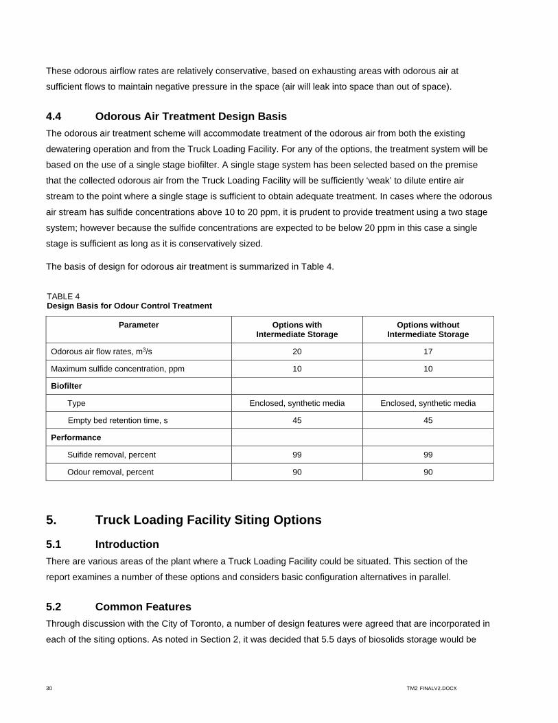
4.4 Odorous Air Treatment Design Basis
The odorous air treatment scheme will accommodate treatment of the odorous air from both the existing
dewatering operation and from the Truck Loading Facility. For any of the options, the treatment system will be
based on the use of a single stage biofilter. A single stage system has been selected based on the premise
that the collected odorous air from the Truck Loading Facility will be sufficiently ‘weak’ to dilute entire air
stream to the point where a single stage is sufficient to obtain adequate treatment. In cases where the odorous
air stream has sulfide concentrations above 10 to 20 ppm, it is prudent to provide treatment using a two stage
system; however because the sulfide concentrations are expected to be below 20 ppm in this case a single
stage is sufficient as long as it is conservatively sized.
The basis of design for odorous air treatment is summarized in Table 4.
TABLE 4 Design Basis for Odour Control Treatment
Parameter Options with Intermediate Storage
Options without Intermediate Storage
Odorous air flow rates, m3/s 20 17
Maximum sulfide concentration, ppm 10 10
Biofilter
Type Enclosed, synthetic media Enclosed, synthetic media
Empty bed retention time, s 45 45
Performance
Suifide removal, percent 99 99
Odour removal, percent 90 90
5. Truck Loading Facility Siting Options
5.1 Introduction
There are various areas of the plant where a Truck Loading Facility could be situated. This section of the
report examines a number of these options and considers basic configuration alternatives in parallel.
5.2 Common Features
Through discussion with the City of Toronto, a number of design features were agreed that are incorporated in
each of the siting options. As noted in Section 2, it was decided that 5.5 days of biosolids storage would be

31 TM2 FINALV2.DOCX
provided to allow for ongoing holding of about two days inventory, additional storage to allow for an
interruption of as much as three days (eg. long weekend or winter storm), as well as providing an additional
half day to re-start the biosolids dewatering processes. This sizing approach mandates the provision of
1,200 m3 of dewatered biosolids storage.
For options that employ the existing biosolids dewatering facility (Option 1 and Option 4), part of the required
total storage volume would be provided by an intermediate stage consisting of two relatively small silos located
in the existing Heat Treatment Area. Biosolids would be transferred from the existing dewatered cake
conveyors to these silos by new conveyors. In turn, the dewatered biosolids would be drawn from the bottom
of these silos into cake pumps that would transfer the material to the V-bottom hoppers, which would feed the
trucks. This arrangement facilitates transition from the existing incineration process to the hauling off-site of
biosolids without substantially disrupting dewatering.
Two of the options that will be discussed later (Option 2 and Option 3) would incorporate new dewatering
facilities, with re-located centrifuges mounted directly above the V-bottom hoppers. In these options, the
hoppers would provide the total storage volume.
Other features common to all options include the following:
The Truck Loading Facility will incorporate two bays, each with two V-bottom bins arranged to enable
dewatered biosolids discharge to one Super-B truck (one tractor and two trailers) or from one of the bins to
one conventional semi-trailer. The provision of two bays allows some overlap in truck loading operations
and ensures that truck loading can continue when one of the bins requires maintenance.
The nominal size of trailer unit allowed in the arrangement is 30 m3. The V-bottom bin live bottoms will be
sized to ensure that this discharge could be accommodated within 30 minutes (60 m3/hour).
Generally, four or five conventional semi-trailer trucks per day would be needed to remove the biosolids
from the site if hauling was continuous for 7 days per week. If hauling is limited to 5 days per week, there
would be six to seven conventional semi-trailer trucks per day. The peak biosolids generation rate would
be close to double the average, so the anticipated maximum traffic load would be 15 conventional semi-
trailer loads per day.
The road layout will accommodate straightforward approach and dispatch geometries with space in the
approach for staging at least one truck outside of the Truck Loading Facility.
Dewatered biosolids will be discharged from piping (Option 1 and Option 4) or from chutes directly from
the centrifuges (Option 2 and Option 3) and distributed between bins by a series of conveyors.
Dewatered biosolids will be distributed along the length of each V-bottom bin through an integrally
mounted horizontal conveyor with multiple discharge ports. This arrangement is intended to optimize
filling efficiency. During further stages of design, it would be prudent to consider the incorporation of
leveling conveyors within the hopper.

32 TM2 FINALV2.DOCX
The distribution conveyors will be arranged with sufficient redundancy to ensure that one hopper can be
removed from service without compromising the function of any other hopper. In options that employ
intermediate buffer storage and dewatered biosolids pumping to the V-bottom bins, this redundancy will be
provided with multiple discharges to the distribution conveyors from each pumped cake line. In options that
incorporate centrifuges mounted above the hoppers, the centrifuge orientation and cross-over conveyors
will be used to allow any centrifuge to discharge to any bin.
Each V-bottom bin will be fitted with six to eight separate discharge ports to spread the discharged
biosolids evenly along the truck trailer bed. The discharge would be controlled by sliding gates with
electrical actuators. The gates would open upon actuation from a central control panel where the truck
drivers would enter the allowed weight of material that their vehicle could reasonably handle. The gates
would close when the discharged weight neared the limit set by the drivers, and as confirmed from the
truck weigh scales mounted below each bin (see below).
Each V-bottom bin will be equipped with level sensors and load cells to provide two measures of the
material weight and volume discharged into and from these hoppers.
The discharge gates from each hopper will be fitted with retractable chutes that direct the dewatered
biosolids into the truck boxes while limiting splatter and spray.
The loading of trucks will be initiated by the truck drivers and thereafter, automated to the degree possible.
Access to the controls will be provided by a card reader and the truck driver will be prompted to enter the
amount of dewatered biosolids that will need to be discharged from each bin to his vehicle. After entering
these values, the control system will open the discharge gates, monitor the weight discharged, and then
close the gates after the appropriate interval.
The headspace of silos and bins will be contained and exhausted to odour control. The existing odorous
air sources also will be re-ducted to odour control (blend tank head space, centrifuge chutes, and centrate
tank headspace). All of this relatively strong odorous air stream will be combined with the more dilute
exhaust from the truck bays and the combined odorous air stream directed to biofilters for treatment. The
biofilters will be constructed in four bays to provide redundancy for the periods when one bay requires
maintenance. Each bay will have a dedicated supply fan and controls to ensure relatively equal distribution
of the odorous air to each bay.
Two weigh scales will be located below each V-bottom bin to allow measurement of the discharged load
from that bin. The trucks will need to move forward or backward to allow measurement of the weight on
the separate axles of the loaded trailers.
The truck loading area will be provided with video cameras to capture and transmit visual information to
the operations staff. These cameras will allow monitoring of truck loading while not requiring the full-time
attendance of plant staff.

33 TM2 FINALV2.DOCX
The truck loading area will be configured to ensure that the doors at both ends would be closed during
loading so that fugitive odorous air emissions could not escape the facility while a truck was being loaded.
The control system will not permit truck loading when a door is open nor will it allow the exit door to optn
when loading is proceeding.
The filled trucks will be subjected to a washdown before exiting the building. Automatic washdown of the
truck body and wheels will accommodate clean-up after truck loading so that trucks do not exit the facility
with evidence of splash or spillage.
5.3 Truck Loading Facility Options – Basic Description
Four Truck Loading Facility options were selected for more detailed comparison, as follows:
1. Option 1 – Master Plan Option (New Truck Loading Facility East of
Existing Biosolids Management Building)
2. Option 2 – Modified Master Plan Option (New Dewatering and Truck Loading Facility East of Existing
Biosolids Management Building)
3. Option 3 - New Dewatering and Truck Loading Facility East of New Dechlorination Building
4. Option 4 – New Truck Loading Facility in Area of Existing Heat Treatment Area
These options are described in more detail in the following subsections. Table 5 summarizes the key capacity
requirements based on the projected 2032 biosolids quantities and outlines the preliminary design basis for
the Truck Loading Facility at the HCTP.

34 TM2 FINALV2.DOCX
TABLE 5 Truck Loading Facility Design Basis Summary
Parameter Value
Biosolids Cake Conveyance
Biosolids cake transferring system capacity 6.0 m3/hr (average biosolids cake production rate) – 11.1 m3/hr (maximum centrifuge output capacity)
Biosolids Cake Storage – General
Storage capacity 5.5 days for max week biosolids cake production rate
Total storage volume (215 m3/d x 5.5 days)1 1,200 m3
Option 1 and Option 4 (with Intermediate Storage)
Intermediate storage silo volume (150 m3 x 2 silos) 300 m3
Number of V-Bottom Bins at the Truck Loading Facility 4 (two bins per loading bay)
Dewatered biosolids cake storage capacity at V-Bottom Bins 900 m3 (225 m3/bin x 4 bins)
Option 2 and Option 3 (without Intermediate Storage)
Number of V-Bottom Bins at the Truck Loading Facility 4 (two bins per loading bay)
Dewatered biosolids cake storage capacity at V-Bottom Bins 1,200 m3 (300 m3/bin x 4 bins)
Biosolids Cake Discharging and Loading
Number of loading bays 2
Capacity of each truck 30 metric tonnes
Loading time 30 min per truck
Discharge capacity (30 metric tonnes/30 min) 60 wet tonnes/hr per loading bay
Wash-down area Integrated into the loading bays
Note: 1. The Biosolids Master Plan for HCTP (AECOM, 2011) recommended that the peak daily biosolids production rate at the
rated capacity for the HCTP was 200 m3 /d. This value is approximately 7% less than the value of 215 m3 /d recommended in this TM because different historical data were used between that study and this TM. However, the difference is considered minor.

35 TM2 FINALV2.DOCX
5.4 Option 1 – Master Plan Option (New Truck Loading Facility East of Existing Biosolids Treatment Facility)
This option includes a new Truck Loading Facility and odour control facility constructed east of the existing
Biosolids Treatment facility. These two elements would be constructed in the south ash ponds, requiring that it
be partially filled to accommodate the new structures. The north ash pond would be This option would entail
the following key elements:
1. The existing dewatering facility (to be refurbished separately, including the replacement of five of the
centrifuges with new units) would be maintained. Dewatered cake that is collected by a series of existing
conveyors below the dewatering floor would discharge into new conveyors.
2. These new conveyors would transfer the material to two new intermediate storage silos with sliding frame
floors, located in the existing heat treatment areas.
3. The intermediate silos would feed new dewatered biosolids pumping equipment that would transfer the
dewatered biosolids to the new Truck Loading Facility.
4. The Truck Loading Facility would be oriented along an east-west axis. Trucks would enter the site and
circle around locations of the ash ponds to approach the new facility from the East. After filling, the loaded
trucks would exit the facility and, and continue west to exit the site through the same gate as which they
entered.
5. The pumped biosolids lines extending from the intermediate storage area to the Truck Loading Facility
would be routed with various other utility lines along an above ground bridge between the existing
Biosolids Management Building and the new Truck Loading Facility. This arrangement reduces the
disruption in this area so that normal operations can continue during construction to the degree possible in
the North Ash Pond.
The process flow diagram, site plan, and sections and elevations for this arrangement are shown in three
drawings attached to this report in Appendix 1. The estimated capital and O&M costs are detailed in
Appendix 2.
Selection of the preferred option will not depend only on costs, but also on the basis of non-monetary
considerations. The following points summarize the more critical concerns that will enter into the choice of the
best option:
Visual Impact A new building, approximately 20 metres tall and 35 metres long will be located along the south boundary of the site. This boundary separates the site from the park and beach area along Lake Ontario and will have significant impact along the waterfront. Architectural treatment will be necessary to ensure that the new structure is acceptable to surrounding residents.
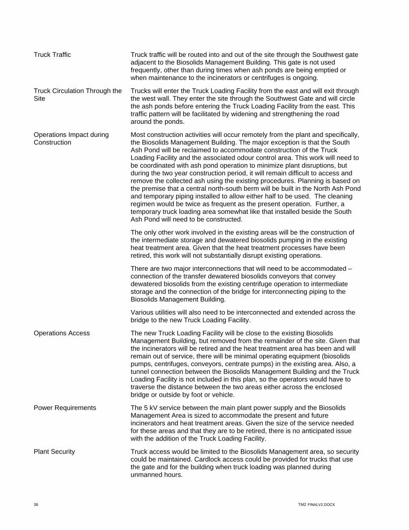
36 TM2 FINALV2.DOCX
Truck Traffic Truck traffic will be routed into and out of the site through the Southwest gate adjacent to the Biosolids Management Building. This gate is not used frequently, other than during times when ash ponds are being emptied or when maintenance to the incinerators or centrifuges is ongoing.
Truck Circulation Through the Site
Trucks will enter the Truck Loading Facility from the east and will exit through the west wall. They enter the site through the Southwest Gate and will circle the ash ponds before entering the Truck Loading Facility from the east. This traffic pattern will be facilitated by widening and strengthening the road around the ponds.
Operations Impact during Construction
Most construction activities will occur remotely from the plant and specifically, the Biosolids Management Building. The major exception is that the South Ash Pond will be reclaimed to accommodate construction of the Truck Loading Facility and the associated odour control area. This work will need to be coordinated with ash pond operation to minimize plant disruptions, but during the two year construction period, it will remain difficult to access and remove the collected ash using the existing procedures. Planning is based on the premise that a central north-south berm will be built in the North Ash Pond and temporary piping installed to allow either half to be used. The cleaning regimen would be twice as frequent as the present operation. Further, a temporary truck loading area somewhat like that installed beside the South Ash Pond will need to be constructed.
The only other work involved in the existing areas will be the construction of the intermediate storage and dewatered biosolids pumping in the existing heat treatment area. Given that the heat treatment processes have been retired, this work will not substantially disrupt existing operations.
There are two major interconnections that will need to be accommodated – connection of the transfer dewatered biosolids conveyors that convey dewatered biosolids from the existing centrifuge operation to intermediate storage and the connection of the bridge for interconnecting piping to the Biosolids Management Building.
Various utilities will also need to be interconnected and extended across the bridge to the new Truck Loading Facility.
Operations Access The new Truck Loading Facility will be close to the existing Biosolids Management Building, but removed from the remainder of the site. Given that the incinerators will be retired and the heat treatment area has been and will remain out of service, there will be minimal operating equipment (biosolids pumps, centrifuges, conveyors, centrate pumps) in the existing area. Also, a tunnel connection between the Biosolids Management Building and the Truck Loading Facility is not included in this plan, so the operators would have to traverse the distance between the two areas either across the enclosed bridge or outside by foot or vehicle.
Power Requirements The 5 kV service between the main plant power supply and the Biosolids Management Area is sized to accommodate the present and future incinerators and heat treatment areas. Given the size of the service needed for these areas and that they are to be retired, there is no anticipated issue with the addition of the Truck Loading Facility.
Plant Security Truck access would be limited to the Biosolids Management area, so security could be maintained. Cardlock access could be provided for trucks that use the gate and for the building when truck loading was planned during unmanned hours.
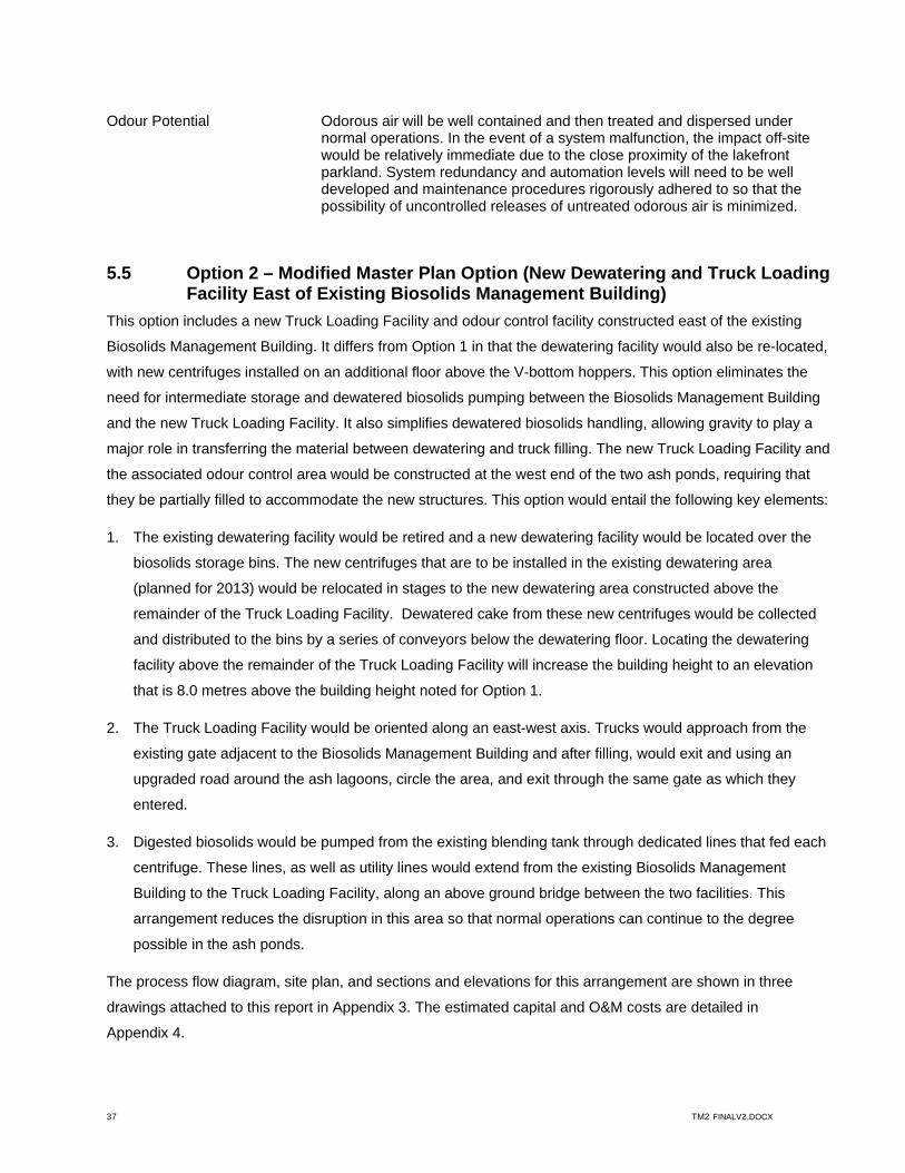
37 TM2 FINALV2.DOCX
Odour Potential Odorous air will be well contained and then treated and dispersed under normal operations. In the event of a system malfunction, the impact off-site would be relatively immediate due to the close proximity of the lakefront parkland. System redundancy and automation levels will need to be well developed and maintenance procedures rigorously adhered to so that the possibility of uncontrolled releases of untreated odorous air is minimized.
5.5 Option 2 – Modified Master Plan Option (New Dewatering and Truck Loading Facility East of Existing Biosolids Management Building)
This option includes a new Truck Loading Facility and odour control facility constructed east of the existing
Biosolids Management Building. It differs from Option 1 in that the dewatering facility would also be re-located,
with new centrifuges installed on an additional floor above the V-bottom hoppers. This option eliminates the
need for intermediate storage and dewatered biosolids pumping between the Biosolids Management Building
and the new Truck Loading Facility. It also simplifies dewatered biosolids handling, allowing gravity to play a
major role in transferring the material between dewatering and truck filling. The new Truck Loading Facility and
the associated odour control area would be constructed at the west end of the two ash ponds, requiring that
they be partially filled to accommodate the new structures. This option would entail the following key elements:
1. The existing dewatering facility would be retired and a new dewatering facility would be located over the
biosolids storage bins. The new centrifuges that are to be installed in the existing dewatering area
(planned for 2013) would be relocated in stages to the new dewatering area constructed above the
remainder of the Truck Loading Facility. Dewatered cake from these new centrifuges would be collected
and distributed to the bins by a series of conveyors below the dewatering floor. Locating the dewatering
facility above the remainder of the Truck Loading Facility will increase the building height to an elevation
that is 8.0 metres above the building height noted for Option 1.
2. The Truck Loading Facility would be oriented along an east-west axis. Trucks would approach from the
existing gate adjacent to the Biosolids Management Building and after filling, would exit and using an
upgraded road around the ash lagoons, circle the area, and exit through the same gate as which they
entered.
3. Digested biosolids would be pumped from the existing blending tank through dedicated lines that fed each
centrifuge. These lines, as well as utility lines would extend from the existing Biosolids Management
Building to the Truck Loading Facility, along an above ground bridge between the two facilities. This
arrangement reduces the disruption in this area so that normal operations can continue to the degree
possible in the ash ponds.
The process flow diagram, site plan, and sections and elevations for this arrangement are shown in three
drawings attached to this report in Appendix 3. The estimated capital and O&M costs are detailed in
Appendix 4.

38 TM2 FINALV2.DOCX
Selection of the preferred option will not depend only on costs, but also on the basis of non-monetary
considerations. The following points summarize the more critical concerns that will enter into the choice of the
best option:
Visual Impact A new building, approximately 28 metres tall and 35 metres long will be located along the south boundary of the site. This boundary separates the site from the park and beach area along Lake Ontario and will have significant impact along the waterfront. Since the building included in this option is even higher (8 metres) than the building envisioned for Option 1, the architectural treatment needed to ensure that the new structure is acceptable to surrounding residents is even more critical.
Truck Traffic Truck traffic will be routed into and out of the site through the Southwest gate adjacent to the Biosolids Management Building. This gate is not used frequently, other than during times when ash ponds are being emptied or when maintenance to the incinerators or centrifuges is ongoing.
Truck Circulation Through the Site
Trucks will enter the Truck Loading Facility from the east and will exit through the west wall. They enter the site through the Southwest Gate and will circle the ash ponds before entering the Truck Loading Facility from the east. This traffic pattern will be facilitated by widening and strengthening the road around the ponds.
Operations Impact during Construction
Most construction activities will occur remotely from the plant and specifically, the Biosolids Management Building. The major exception is that the South Ash Pond will be reclaimed to accommodate construction of the Truck Loading Facility and the associated odour control area. This work will need to be coordinated with ash pond operation to minimize plant disruptions, but during the two year construction period, it will remain difficult to access and remove the collected ash using the existing procedures. Planning is based on the premise that a central north-south berm will be built in the North Ash Pond and temporary piping installed to allow either half to be used. The cleaning regimen would be twice as frequent as the present operation. Further, a temporary truck loading area somewhat like that installed beside the South Ash Pond will need to be constructed.
The only other work involved in the existing areas will be the installation of new centrifuge feed pumps and the associated piping in the blending tank area. This work will need to be planned to facilitate logical cross-over to the new facility when possible..
There is one major interconnections that will need to be accommodated – the connection of the bridge for interconnecting piping to the Biosolids Management Building.
New centrate piping from the new dewatering area to the existing centrate pumps as well as the interconnection of various utilities also will be needed.
Operations Access The new Truck Loading Facility will be close to the existing Biosolids Management Building, but removed from the remainder of the site. Given that the existing dewatering area and the incinerators will be retired and the heat treatment area has been and will remain out of service, there will be almost no operating equipment (biosolids pumps, centrate pumps) in the existing area.
A tunnel connection between the Biosolids Management Building and the Truck Loading Facility is not included in this plan, so the operators would have to traverse the distance between the two areas either across the enclosed bridge or outside by foot or vehicle.
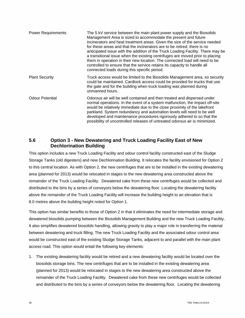
39 TM2 FINALV2.DOCX
Power Requirements The 5 kV service between the main plant power supply and the Biosolids Management Area is sized to accommodate the present and future incinerators and heat treatment areas. Given the size of the service needed for these areas and that the incinerators are to be retired, there is no anticipated issue with the addition of the Truck Loading Facility. There may be a transitional issue when the existing centrifuges are moved prior to placing them in operation in their new location. The connected load will need to be controlled to ensure that the service retains its capacity to handle all connected loads during this specific period.
Plant Security Truck access would be limited to the Biosolids Management area, so security could be maintained. Cardlock access could be provided for trucks that use the gate and for the building when truck loading was planned during unmanned hours.
Odour Potential Odorous air will be well contained and then treated and dispersed under normal operations. In the event of a system malfunction, the impact off-site would be relatively immediate due to the close proximity of the lakefront parkland. System redundancy and automation levels will need to be well developed and maintenance procedures rigorously adhered to so that the possibility of uncontrolled releases of untreated odorous air is minimized.
5.6 Option 3 - New Dewatering and Truck Loading Facility East of New Dechlorination Building
This option includes a new Truck Loading Facility and odour control facility constructed east of the Sludge
Storage Tanks (old digesters) and new Dechlorination Building. It relocates the facility envisioned for Option 2
to this central location. As with Option 2, the new centrifuges that are to be installed in the existing dewatering
area (planned for 2013) would be relocated in stages to the new dewatering area constructed above the
remainder of the Truck Loading Facility. Dewatered cake from these new centrifuges would be collected and
distributed to the bins by a series of conveyors below the dewatering floor. Locating the dewatering facility
above the remainder of the Truck Loading Facility will increase the building height to an elevation that is
8.0 metres above the building height noted for Option 1.
This option has similar benefits to those of Option 2 in that it eliminates the need for intermediate storage and
dewatered biosolids pumping between the Biosolids Management Building and the new Truck Loading Facility.
It also simplifies dewatered biosolids handling, allowing gravity to play a major role in transferring the material
between dewatering and truck filling. The new Truck Loading Facility and the associated odour control area
would be constructed east of the existing Sludge Storage Tanks, adjacent to and parallel with the main plant
access road. This option would entail the following key elements:
1. The existing dewatering facility would be retired and a new dewatering facility would be located over the
biosolids storage bins. The new centrifuges that are to be installed in the existing dewatering area
(planned for 2013) would be relocated in stages to the new dewatering area constructed above the
remainder of the Truck Loading Facility. Dewatered cake from these new centrifuges would be collected
and distributed to the bins by a series of conveyors below the dewatering floor. Locating the dewatering

40 TM2 FINALV2.DOCX
facility above the remainder of the Truck Loading Facility will increase the building height to an elevation
that is 8.0 metres above the building height noted for Option 1.
2. The Truck Loading Facility would be oriented along an east-west axis. Trucks would enter through the
existing main gate and drive along that road until a point just beyond the new Truck Loading Facility. At
this point, they would initiate a long 180 degree turn to enter the facility from the east. After loading, they
would exit the building to the west and then would maneuver to re-join the main plant road. They would
exit the site through the main plant road.
3. Digested biosolids would be transferred from the existing Storage Tanks through a new line to a blend
tank below grade. From this tank, new centrifuge feed pumps would feed each unit. The biosolids transfer
lines, as well as utility lines, would extend from the existing Sludge Storage Tank Area to the Truck
Loading Facility, in parallel with various utility lines, through a below ground pipe chase.
The process flow diagram, site plan, and sections and elevations for this arrangement are shown in three
drawings attached to this report in Appendix 5. The estimated capital and O&M costs are detailed in
Appendix 6.
Selection of the preferred option will not depend only on costs, but also on the basis of non-monetary
considerations. The following points summarize the more critical concerns that will enter into the choice of the
best option:
Visual Impact The new building, of the same size as that envisioned for Option 2, will be located centrally on the site. Removing the building from site boundaries minimizes the visual impact along the waterfront or in other adjacent areas. The architectural treatment required to satisfy surrounding residents will be less critical.
Truck Traffic Truck traffic will be routed into the site through the main gate and after loading will will return along the same road. The traffic may interfere with normal plant operations to some degree, although the main road has minimal traffic on an ongoing basis other than its use for chemical deliveries.
Truck Circulation Through the Site
To accommodate the truck traffic along the main road, it would be widened from its current 6 metre width to at least 7.5 metres. Additionally, some modifications to radii at corners will be needed to handle the wide turning radii of the trucks.
Operations Impact during Construction
Most construction activities will occur remotely from the plant and specifically, the Biosolids Management Building. The ash ponds will not be affected. Construction traffic in this area should not differ substantially from that already ongoing in a similar area for the construction of a new WAS thickening facility.
The only other work involved in the existing areas will be the installation of new centrifuge feed pumps and the associated piping in the Storage Tank area. This work will need to be planned to facilitate logical cross-over to the new facility when possible.
The new Truck Loading Facility will incorporate a number of underground tanks – two blend tanks for the biosolids transferred from the Sludge Storage Area and one centrate tank (centrate could drain by gravity to the plant sewer; however, this small tank will allow for foam suppression prior to discharge to the
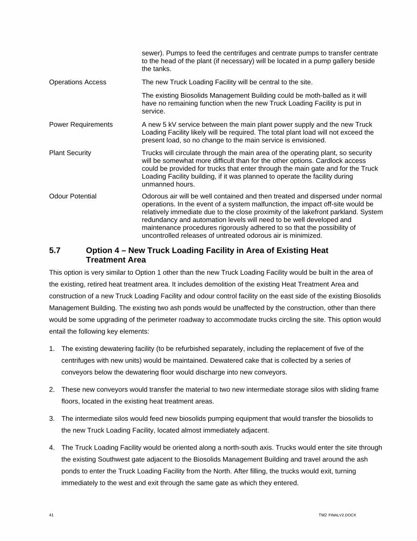
41 TM2 FINALV2.DOCX
sewer). Pumps to feed the centrifuges and centrate pumps to transfer centrate to the head of the plant (if necessary) will be located in a pump gallery beside the tanks.
Operations Access The new Truck Loading Facility will be central to the site.
The existing Biosolids Management Building could be moth-balled as it will have no remaining function when the new Truck Loading Facility is put in service.
Power Requirements A new 5 kV service between the main plant power supply and the new Truck Loading Facility likely will be required. The total plant load will not exceed the present load, so no change to the main service is envisioned.
Plant Security Trucks will circulate through the main area of the operating plant, so security will be somewhat more difficult than for the other options. Cardlock access could be provided for trucks that enter through the main gate and for the Truck Loading Facility building, if it was planned to operate the facility during unmanned hours.
Odour Potential Odorous air will be well contained and then treated and dispersed under normal operations. In the event of a system malfunction, the impact off-site would be relatively immediate due to the close proximity of the lakefront parkland. System redundancy and automation levels will need to be well developed and maintenance procedures rigorously adhered to so that the possibility of uncontrolled releases of untreated odorous air is minimized.
5.7 Option 4 – New Truck Loading Facility in Area of Existing Heat Treatment Area
This option is very similar to Option 1 other than the new Truck Loading Facility would be built in the area of
the existing, retired heat treatment area. It includes demolition of the existing Heat Treatment Area and
construction of a new Truck Loading Facility and odour control facility on the east side of the existing Biosolids
Management Building. The existing two ash ponds would be unaffected by the construction, other than there
would be some upgrading of the perimeter roadway to accommodate trucks circling the site. This option would
entail the following key elements:
1. The existing dewatering facility (to be refurbished separately, including the replacement of five of the
centrifuges with new units) would be maintained. Dewatered cake that is collected by a series of
conveyors below the dewatering floor would discharge into new conveyors.
2. These new conveyors would transfer the material to two new intermediate storage silos with sliding frame
floors, located in the existing heat treatment areas.
3. The intermediate silos would feed new biosolids pumping equipment that would transfer the biosolids to
the new Truck Loading Facility, located almost immediately adjacent.
4. The Truck Loading Facility would be oriented along a north-south axis. Trucks would enter the site through
the existing Southwest gate adjacent to the Biosolids Management Building and travel around the ash
ponds to enter the Truck Loading Facility from the North. After filling, the trucks would exit, turning
immediately to the west and exit through the same gate as which they entered.

42 TM2 FINALV2.DOCX
The process flow diagram, site plan, and sections and elevations for this arrangement are shown in three
drawings attached to this report in Appendix 7. The estimated capital and O&M costs are detailed in
Appendix 8.
Selection of the preferred option will not depend only on costs, but also on the basis of non-monetary
considerations. The following points summarize the more critical concerns that will enter into the choice of the
best option:
Visual Impact There would be minimal impact. The new Truck Loading Facility would replace the building – providing a similar footprint and visual impact, although it would be somewhat higher. (Note – pricing has been based on complete upper structure demolition and replacement with a new structure).
Truck Traffic Truck traffic will be routed into and out of the site through the Southwest gate adjacent to the Biosolids Management Building. This gate is not used frequently, other than during times when ash ponds are being emptied or when maintenance to the incinerators or centrifuges is ongoing.
Truck Circulation Through the Site
Trucks will enter the Truck Loading Facility from the west and will exit through the east wall. They will circle the ash ponds before exiting the site through the Southwest gate. This traffic pattern will be facilitated by widening and strengthening the road around the ponds.
Operations Impact during Construction
Almost all construction activities will occur within the existing Biosolids Management Building and will require substantial coordination with the operating staff to minimize disruption of operations. However, there should be minimal or no disruption of ash pond operation during construction.
The only other work involved in the existing areas will be the construction of the intermediate storage and biosolids pumping in the existing heat treatment area. Given that the heat treatment processes have been retired, this work will not substantially disrupt existing operations.
For the truck loading area, it is envisioned that the existing heat treatment area floor slab would be retained. The installation of the weigh scales will need a substantial amount of rework. The support of these scales and the above ground storage facilities may require a significant amount of underpinning and reinforcement of the existing structure and slab. These activities would tend to disrupt existing plant operations, especially in the area of the existing centrate tanks and blending tanks.
The odour control facility constructed for the new Truck Loading Facility would be located in the northernmost ash pond, so would disrupt normal operations in that pond during construction. Clean-out would have to be coordinated with the Contractor’s activities and the capacity would be reduced until it could be retired when the new Truck Loading Facility was put in service.
The only major interconnections that will need to be accommodated is the connection of the new biosolids conveyors that transfer dewatered biosolids from the existing centrifuge operation to intermediate storage silos.
Various utilities will also need to be interconnected to the new Truck Loading Facility.

43 TM2 FINALV2.DOCX
Operations Access The new Truck Loading Facility will be close to the existing Biosolids Management Building, but removed from the remainder of the site. Given that the incinerators will be retired and the heat treatment area has been and will remain out of service, the operating equipment inventory will be similar to that envisioned for Option 2 and Option 3. Because the new facility will be in the same location as the heat treatment areas, the operators will not have to traverse the distance between the two areas.
Power Requirements The 5 kV service between the main plant power supply and the Biosolids Management Area is sized to accommodate the present and future incinerators and heat treatment areas. Given the size of the service needed for these areas and that they are to be retired, there is no anticipated issue with the addition of the Truck Loading Facility.
Plant Security Truck access would be limited to the Biosolids Management area, so security could be maintained. Cardlock access could be provided for trucks that enter through the Southwest gate and for the building if it was planned to operate the facility during unmanned hours.
Odour Potential Odorous air will be well contained and then treated and dispersed under normal operations. In the event of a system malfunction, the impact off-site would be relatively immediate due to the close proximity of the lakefront parkland. System redundancy and automation levels will need to be well developed and maintenance procedures rigorously adhered to so that the possibility of uncontrolled releases of untreated odorous air is minimized.
6. Cost Comparison of Options
6.1 Capital Cost Estimates
Class 4 capital cost estimates have been prepared for the four options considered for the Truck Loading
Facility. These estimates are based on vendor proposals for major equipment, unit prices for structural aspects
of the work as well as similar elements constructed at other wastewater treatment plants, plus allowances for
various components based on complexity and scope.
The scope of the elements of the cost estimate and major assumptions made in the development of these
estimates are described and discussed in the following:
Scope General Requirements: the contractual requirements for site management (construction trailers,
communications, power, lighting, sanitary facilities, safety, etc), as well as for bonding, insurance, and
mobilization. It also includes allowances for project management and profit for the General
Contractor.
Civil: excavation and grading, roadwork, roadway lighting, pathways, landscaping, and underground
utilities.

44 TM2 FINALV2.DOCX
Structural: the foundations, substructure, and superstructure. In this case, the architectural and
finishing components of a contractor’s bid have also been included – masonry, roofing, waterproofing,
finishes, and other special construction.
Process mechanical: supply and installation of process equipment. Process mechanical also includes
the process piping.
Utility mechanical: plumbing and heating, ventilation and air conditioning (HVAC), including utility
piping inside the buildings.
Electrical: power supply, power distribution and control, lighting, and electrical protection.
Instrumentation and Control: process control elements, building safety monitoring and control,
security, SCADA
Major Assumptions Option 2 and Option 3 include moving dewatering from the Biosolids Management Facility. It was
assumed that the centrifuges would be relocated to the new facility. Toronto is planning on replacing
five of the six operating centrifuges in the next two years. It is these relatively new units that would be
moved.
The civil work would include demolition as required. Option 3 includes demolition of the old anaerobic
filters to accommodate construction of the new Truck Loading Facility. For Option 4, demolition
includes the removal of the existing heat treatment area superstructure as well as demolition of the
existing decant tanks to facilitate the access roadways to the Truck Loading Facliity.
For Option 1, Option 2, and Option 4; the existing blending tanks and the centrate tanks would remain
in service. For Option 3, because of its location, new blend tanks and centrate tanks would be
constructed.
The estimate at this stage of project development is considered to have Class 4 accuracy, or accurate to
within -30 percent / +50 percent. The detailed capital costs developed for each option are attached to this
report in a series of Appendices (Appendix 2, Appendix 4, Appendix 6, and Appendix 8). Table 6 summarizes
these estimates.
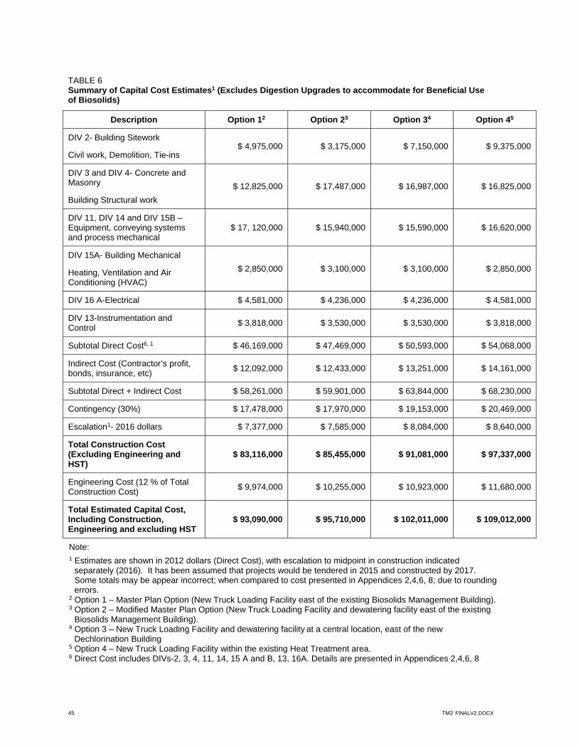
45 TM2 FINALV2.DOCX
TABLE 6 Summary of Capital Cost Estimates1 (Excludes Digestion Upgrades to accommodate for Beneficial Use of Biosolids)
Description Option 12 Option 23 Option 34 Option 45
DIV 2- Building Sitework
Civil work, Demolition, Tie-ins $ 4,975,000 $ 3,175,000 $ 7,150,000 $ 9,375,000
DIV 3 and DIV 4- Concrete and Masonry
Building Structural work
$ 12,825,000 $ 17,487,000 $ 16,987,000 $ 16,825,000
DIV 11, DIV 14 and DIV 15B –Equipment, conveying systems and process mechanical
$ 17, 120,000 $ 15,940,000 $ 15,590,000 $ 16,620,000
DIV 15A- Building Mechanical
Heating, Ventilation and Air Conditioning (HVAC)
$ 2,850,000 $ 3,100,000 $ 3,100,000 $ 2,850,000
DIV 16 A-Electrical $ 4,581,000 $ 4,236,000 $ 4,236,000 $ 4,581,000
DIV 13-Instrumentation and Control
$ 3,818,000 $ 3,530,000 $ 3,530,000 $ 3,818,000
Subtotal Direct Cost6, 1 $ 46,169,000 $ 47,469,000 $ 50,593,000 $ 54,068,000
Indirect Cost (Contractor’s profit, bonds, insurance, etc)
$ 12,092,000 $ 12,433,000 $ 13,251,000 $ 14,161,000
Subtotal Direct + Indirect Cost $ 58,261,000 $ 59,901,000 $ 63,844,000 $ 68,230,000
Contingency (30%) $ 17,478,000 $ 17,970,000 $ 19,153,000 $ 20,469,000
Escalation1- 2016 dollars $ 7,377,000 $ 7,585,000 $ 8,084,000 $ 8,640,000
Total Construction Cost (Excluding Engineering and HST)
$ 83,116,000 $ 85,455,000 $ 91,081,000 $ 97,337,000
Engineering Cost (12 % of Total Construction Cost)
$ 9,974,000 $ 10,255,000 $ 10,923,000 $ 11,680,000
Total Estimated Capital Cost, Including Construction, Engineering and excluding HST
$ 93,090,000 $ 95,710,000 $ 102,011,000 $ 109,012,000
Note: 1 Estimates are shown in 2012 dollars (Direct Cost), with escalation to midpoint in construction indicated
separately (2016). It has been assumed that projects would be tendered in 2015 and constructed by 2017. Some totals may be appear incorrect; when compared to cost presented in Appendices 2,4,6, 8; due to rounding errors.
2 Option 1 – Master Plan Option (New Truck Loading Facility east of the existing Biosolids Management Building). 3 Option 2 – Modified Master Plan Option (New Truck Loading Facility and dewatering facility east of the existing
Biosolids Management Building). 4 Option 3 – New Truck Loading Facility and dewatering facility at a central location, east of the new
Dechlorination Building 5 Option 4 – New Truck Loading Facility within the existing Heat Treatment area. 6 Direct Cost includes DIVs-2, 3, 4, 11, 14, 15 A and B, 13, 16A. Details are presented in Appendices 2,4,6, 8
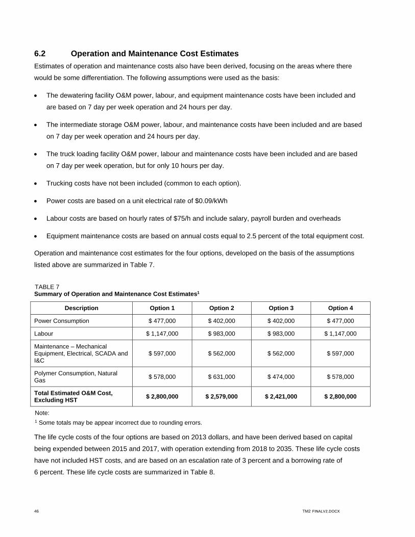
46 TM2 FINALV2.DOCX
6.2 Operation and Maintenance Cost Estimates
Estimates of operation and maintenance costs also have been derived, focusing on the areas where there
would be some differentiation. The following assumptions were used as the basis:
The dewatering facility O&M power, labour, and equipment maintenance costs have been included and
are based on 7 day per week operation and 24 hours per day.
The intermediate storage O&M power, labour, and maintenance costs have been included and are based
on 7 day per week operation and 24 hours per day.
The truck loading facility O&M power, labour and maintenance costs have been included and are based
on 7 day per week operation, but for only 10 hours per day.
Trucking costs have not been included (common to each option).
Power costs are based on a unit electrical rate of $0.09/kWh
Labour costs are based on hourly rates of $75/h and include salary, payroll burden and overheads
Equipment maintenance costs are based on annual costs equal to 2.5 percent of the total equipment cost.
Operation and maintenance cost estimates for the four options, developed on the basis of the assumptions
listed above are summarized in Table 7.
TABLE 7 Summary of Operation and Maintenance Cost Estimates1
Description Option 1 Option 2 Option 3 Option 4
Power Consumption $ 477,000 $ 402,000 $ 402,000 $ 477,000
Labour $ 1,147,000 $ 983,000 $ 983,000 $ 1,147,000
Maintenance – Mechanical Equipment, Electrical, SCADA and I&C
$ 597,000 $ 562,000 $ 562,000 $ 597,000
Polymer Consumption, Natural Gas
$ 578,000 $ 631,000 $ 474,000 $ 578,000
Total Estimated O&M Cost, Excluding HST
$ 2,800,000 $ 2,579,000 $ 2,421,000 $ 2,800,000
Note: 1 Some totals may be appear incorrect due to rounding errors. The life cycle costs of the four options are based on 2013 dollars, and have been derived based on capital
being expended between 2015 and 2017, with operation extending from 2018 to 2035. These life cycle costs
have not included HST costs, and are based on an escalation rate of 3 percent and a borrowing rate of
6 percent. These life cycle costs are summarized in Table 8.
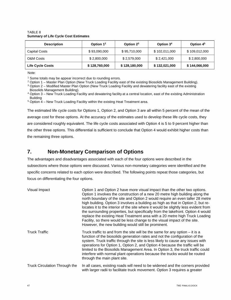
47 TM2 FINALV2.DOCX
TABLE 8 Summary of Life Cycle Cost Estimates
Description Option 12 Option 23 Option 34 Option 45
Capital Costs $ 93,090,000 $ 95,710,000 $ 102,011,000 $ 109,012,000
O&M Costs $ 2,800,000 $ 2,579,000 $ 2,421,000 $ 2,800,000
Life Cycle Costs $ 128,760,000 $ 128,180,000 $ 132,021,000 $ 144,066,000
Note: 1 Some totals may be appear incorrect due to rounding errors. 2 Option 1 – Master Plan Option (New Truck Loading Facility east of the existing Biosolids Management Building). 3 Option 2 – Modified Master Plan Option (New Truck Loading Facility and dewatering facility east of the existing
Biosolids Management Building). 4 Option 3 – New Truck Loading Facility and dewatering facility at a central location, east of the existing Administration
Building
5 Option 4 – New Truck Loading Facility within the existing Heat Treatment area.
The estimated life cycle costs for Options 1, Option 2, and Option 3 are all within 5 percent of the mean of the
average cost for these options. At the accuracy of the estimates used to develop these life cycle costs, they
are considered roughly equivalent. The life cycle costs associated with Option 4 is 5 to 9 percent higher than
the other three options. This differential is sufficient to conclude that Option 4 would exhibit higher costs than
the remaining three options.
7. Non-Monetary Comparison of Options The advantages and disadvantages associated with each of the four options were described in the
subsections where those options were discussed. Various non-monetary categories were identified and the
specific concerns related to each option were described. The following points repeat those categories, but
focus on differentiating the four options.
Visual Impact Option 1 and Option 2 have more visual impact than the other two options. Option 1 involves the construction of a new 20 metre high building along the north boundary of the site and Option 2 would require an even taller 28 metre high building. Option 3 involves a building as high as that in Option 2, but re-locates it to the interior of the site where it would be slightly less evident from the surrounding properties, but specifically from the lakefront. Option 4 would replace the existing Heat Treatment area with a 20 metre high Truck Loading Facility, so there would be less change to the visual impact of the site. However, the new building would still be prominent.
Truck Traffic Truck traffic to and from the site will be the same for any option – it is a function of the biosolids generation rates and not the configuration of the system. Truck traffic through the site is less likely to cause any issues with operations for Option 1, Option 2, and Option 4 because the traffic will be limited to the Biosolids Management Area. In Option 3, the truck traffic could interfere with normal plant operations because the trucks would be routed through the main plant site.
Truck Circulation Through the In all cases, existing roads will need to be widened and the corners provided with larger radii to facilitate truck movement. Option 3 requires a greater

48 TM2 FINALV2.DOCX
Site amount of work because the roads through the main plant area are incapable of handling substantial truck traffic and because the ability of trucks to turn around to exit the site is limited.
Operations Impact during Construction
Option 3 structures and process work would have the least impact on existing operations – most of the work could be completed off line and interconnections made in a manner that did not disrupt normal operations. However, the site is within the existing main plant area so there would be some interference due to construction traffic. The other options require some work in the existing Biosolids Management Building. Option 2 needs the least, while Option 1 and Option 4 mandate substantial effort in these areas. Option 4 would require significant rebuilding of the structures in the present location of the Heat Treatment areas. Option 1, Option 2, and Option 4 construction all would interfere with the normal operation of the ash ponds because all or some of the facilities would be located in reclaimed areas of these basins.
Operations Access Option 3 offers the best operator access to the facility because it is located within the existing plant area and could be integrated into the tunnel system with minimal additional effort. Option 4 is also relatively accessible to operations staff because it would locate the Truck Loading Facility in the existing Heat Treatment Area, which is linked to the remainder of the plant. Foot and vehicular traffic would need to travel across an elevated bridge or outside the existing buildings to obtain access to the new Truck Loading Facility site envisioned for Option 1 and Option 2.
Power Requirements Option 1, Option 2, and Option 4 could all be served from the existing feed to the Biosolids Management Building, although there may be some transition issues when the new facility is brought on line. Option 3 would require a new 5 kV feed from the plant substation. In no case is it considered likely that the main plant service capacity will be exceeded due to the new loads associated with the Truck Loading Facility – they are much less than the loads of the retired biosolids management processes (heat treatment, incineration).
Plant Security Option 3 has some security concerns because private trucks would enter and circulate through the main plant site. The other three options limits this access to the biosolids management areas.
Odour Potential There are minimal differences between odour potential of the three options. Option 3 does have some minor advantage because the odour sources would be moved further from the plant boundary.
8. Recommended Option Capital cost and operation and maintenance (O&M) cost estimates were prepared to allow comparison of
these four options. Option 1 and Option 2 were almost equal and enjoyed a capital cost advantage over
Option 3 and Option 4, even when considering long term O&M costs. The following table outlines the relative
merits of the two options.
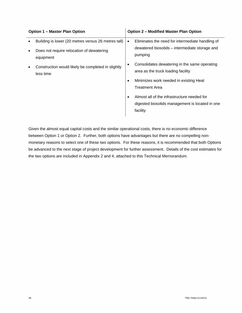
49 TM2 FINALV2.DOCX
Option 1 – Master Plan Option Option 2 – Modified Master Plan Option
Building is lower (20 metres versus 26 metres tall)
Does not require relocation of dewatering
equipment
Construction would likely be completed in slightly
less time
Eliminates the need for intermediate handling of
dewatered biosolids – intermediate storage and
pumping
Consolidates dewatering in the same operating
area as the truck loading facility
Minimizes work needed in existing Heat
Treatment Area
Almost all of the infrastructure needed for
digested biosolids management is located in one
facility
Given the almost equal capital costs and the similar operational costs, there is no economic difference
between Option 1 or Option 2. Further, both options have advantages but there are no compelling non-
monetary reasons to select one of these two options. For these reasons, it is recommended that both Options
be advanced to the next stage of project development for further assessment. Details of the cost estimates for
the two options are included in Appendix 2 and 4, attached to this Technical Memorandum.

Appendix 1 Option 1 Drawings
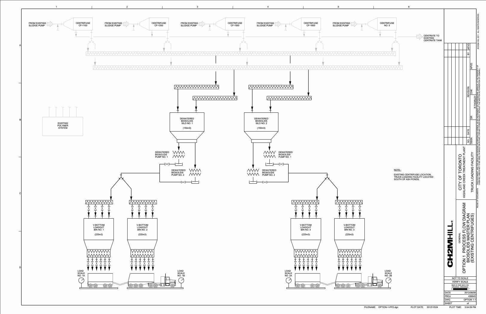
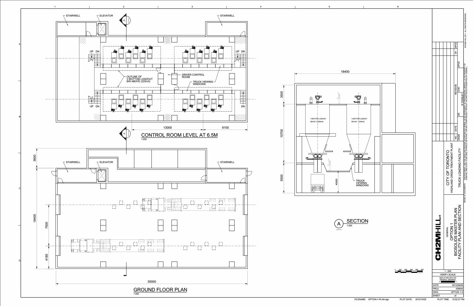
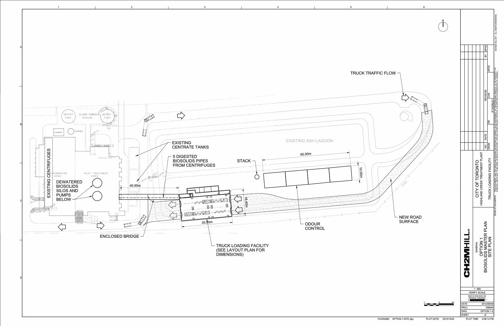

Appendix 2 Option 1 Cost Estimate

Option 1
Component Description Quantity Unit Unit Cost Material Cost Total Cost
% of Matl Cost
Div 1 - General Requirements
General Requirements- Covers the general contractor's site cost such as office trailer, site staff, small tools and equipment, permits, cleanup, testing & start-up.
Included in General Conditions Below
Sub-Total Division 1 - General Requirements -$
Div 2 - Building Sitework
Civil Work- South Ash Lagoon removal and fill, a
new 2 lane asphalt access road, Miscellaneous
rough grading. 1 sum 1,990,000.00$ -$ -$ incl. 1,990,000$ Civil Work- North Ash Lagoon removal and
associated fill 1 sum 885,000.00$ -$ -$ incl. 885,000$
Demolition (Tie-in for Bridge and Demolition of Heat Exchangers) 1 sum 2,000,000.00$ -$ -$ incl. 2,000,000$ Tie-In Allowances to Existing Biosolids
Managemetn Facility. 1 sum 100,000.00$ -$ -$ incl. 100,000$
Sub-Total Division 2 - Building Sitework 4,975,000$
Div 3 - Concrete
Building - (Architectural, Structural) 5,756 m21,620.00$ 9,324,720.00$ -$ Incl. 9,324,720$
Sub-Total Division 3 - Concrete 9,324,700$
Div 4 - MasonryEnclosed Bridge-Concrete support/Steel and Metal Sidding 1 sum 2,500,000.00$ -$ -$ Incl. 2,500,000$
Stack 1 sum 1,000,000.00$ -$ -$ Incl. 1,000,000$
Sub-Total Division 4 - Masonry 3,500,000$
Div 5 - Metals
Metals - INCLUDED IN DIV 3 -$
Sub-Total Division 5 - Metals -$
Div 6 - Wood & Plastics
Wood and Plastics- INCLUDED IN DIV 3 -$
Sub-Total Division 6 - Wood & Plastics -$
Div 7 - Thermal and Moisture Protection
Thermal and Moisture Protection- INCLUDED IN DIV 3 -$
Sub-Total Division 7 - Thermal and Moisture Protection
-$
Div 8 - Doors and Windows
Doors and Windows- INCLUDED IN DIV 3 -$
Sub-Total Division 8 - Doors and Windows-$
Div 9 - Finishes
Finishes- INCLUDED IN DIV 3 -$
Sub-Total Division 9 - Finishes -$
Div 10 - Specialties
Specialties- INCLUDED IN DIV 3 -$
Sub-Total Division 10 - Specialties -$
Div 11 - Equipment
-Truck Loading Facility Equipment
Conveyors-top of v-bottom bins 4 each 70,000.00$ 280,000$ 50% 140,000$ 420,000$ V-Bottom Bins Storage (4.5 Days); 2 Schwing Pumps; 2 Silos Storage (1.5 Days) 4 package 7,500,000$ -$ 30% 2,250,000 9,750,000$
Weight Scales 8 each 200,000.00$ 1,600,000$ 50% 800,000$ 2,400,000$
-Odour Control Facility Equipment
Odour Control Biofilter 1 package 1,500,000.00$ 1,500,000$ 50% 750,000$ 2,250,000$
-Dewatering Equipment
Dewatered Biosolids Screw Conveyors 2 each 150,000.00$ 300,000$ 50% 150,000$ 450,000$
Sub-Total Division 11 - Equipment 15,270,000$
Div 13 - Special Construction I&C
Master Plan Option (New Truck Loading Facility East of Existing Biosolids Management Facility)- Option 1 Cost Estimate(1)
Installation
01-CapitalCost. - option1.xls - option11 of 2 11/5/2012

Option 1
Component Description Quantity Unit Unit Cost Material Cost Total Cost
% of Matl Cost
Master Plan Option (New Truck Loading Facility East of Existing Biosolids Management Facility)- Option 1 Cost Estimate(1)
Installation
Instrument Control Panel (ICP), PLC System - Software and Hardware 1 sum 3,817,500.00$ -$ -$ Incl. 3,817,500$
-Estimated as 25% of Equipment cost(DIV 11)
Sub-Total Division 13 - Special Construction I&C
3,817,500$
Div 14 -Conveying Systems
Bridge Crane (allow for Lifting Schwing Pump ) 1 sum 150,000.00$ -$ -$ Incl. 150,000$
Sub-Total Division 14 - Conveying Systems 150,000$
Div 15A - Building Mechanical
Exhaust Fans/ Heaters 1 sum 450,000$ -$ -$ incl. 450,000$
Sump Pump allowances 1 sum 150,000$ -$ -$ incl. 150,000$
Make Up Air Units/Dehumidication Units 1 sum 1,500,000$ -$ -$ incl. 1,500,000$
Duct Work 1 sum 750,000$ -$ -$ incl. 750,000$
Sub-Total Division 15A - Building Mechanical 2,850,000$
Div 15B - Process Mechanical
5 (300 mm sst), 250m Digested Sludge Piping 1 sum 450,000.00$ -$ -$ incl. 450,000$
250 knife valves & Actuators 16 each 30,000.00$ 480,000$ 50% 240,000$ 720,000$
High Pressure Ball Valves valves- 600 psi 4 each 30,000.00$ 120,000$ 50% 60,000$ 180,000$
2 (450) Centrate Pipes- 140 m 1 sum 250,000.00$ -$ -$ incl. 250,000$
Miscellaneous Piping 1 sum 100,000.00$ -$ -$ incl. 100,000$
Sub-Total Division 15B - Process Mechanical 1,700,000$
Div 16A - Electrical
Electrical - Supply and Install 1 sum 4,581,000.00$ 4,581,000$ -$ incl. 4,581,000$
-Estimated as 30% of Equipment Cost (DIV 11)
Sub-Total Division 16A- Electrical 4,581,000$
Sub-Total Basic Facility Costs (Direct Cost) 46,168,210$
Indirect Cost
Contract Staff & Home Office OH 8.00% 3,693,457$
Sub-Total 49,861,667$
General Conditions 7.00% 3,490,317$
Sub-Total 53,351,983$
Mobilization/Demobilization 2.00% 1,067,040$
Insurance 1.00% 533,520$
Bond 1.00% 533,520$
Sub-Total 55,486,063$
Profit 5.00% 2,774,303$
Sub-Total 58,260,366$
Indirect Cost Subtotal 12,092,156$
Contingency 30.00% 17,478,110$
Sub-Total 75,738,476$
Escalation to Mid-point of Construction2 (2016) 9.74% 7,376,928$
Total Construction Cost (Excluding Engineering and HST) 83,115,403$
Engineering Cost (12% of Total Construction Cost) 12.00% 9,973,848$
HST 13% 10,805,002$
Total Estimated Capital Cost, Including Construction, Engineering and Excluding HST 93,089,252$
Total Estimated Capital Cost, Including HST 103,894,254$ (1) The Cost Estimate have been prepared for guidance in project evaluation and implementation from the information available at the time the estimate was prepared. These estimates are considered Order of Magnitude Estimates by the American Association of
Cost Engineers (AACE). This level of estimate is expected to be accuate to within plus 50% to minus 30% of the costs prepared.
(2) Estimates are shown in 2012 dollars, with escalation to midpoint in construction indicated separately (2016). It has been assumed that projects would be tendered in 2015 and constructed by 2017.
01-CapitalCost. - option1.xls - option12 of 2 11/5/2012

OPERATION AND MAINTENANCE COST
1- Power Consumption
EquipmentNo of Operating
UnitsOperating Hours
per DayPower Draw per
Unit $/yr-Process Equipment-
Centrifuges 2 24 150 236,520$
Digested Sludge Pumps 2 24 15 23,652$
Biosolids Pumps (Schwing Pumps) 1 24 75 59,130$
Sliding Frame - Biosolids Storage Silo 1 24 30 23,652$
Conveyors 2 24 20 31,536$
V-Bottom Bin conveyors 2 8 15 7,884$
Odour Control Fans 2 24 20 31,536$
Miscellaneous Small Equipment 1 24 30 23,652$
-Building Mechanical-electrical room heater/Fans (all included) 1 24 50 39,420$
(Smaller Building)TOTAL Annual Power Cost 476,982$
2- Operating Labour Operating Labour Days per Week Shifts per Day Hours per Shift $/yr
Dewatering 7 3 8 655,200$
Intermediate Storage 7 3 2 163,800$
Truck Loading Facility 7 1 6 163,800$
Odour Control 7 3 2 163,800$
TOTAL Labour Cost 1,146,600$
3- Maintenance Mechanical Equipment (2.5 % Equipment Cost as Div 11)Div 11 Equipment Total 15,270,000$ 381,750$
Existing Centrifuges 5,250,000$ 131,250$
TOTAl Maintenace Cost 513,000$
4- Polymer Consumption Kg/year
Polymer Consumption 115000 4.12 $/Kg 473,800$
TOTAl Polymer Cost 473,800$
5- Natural Gas Biosolids Management m3/hr
Natural Gas Consumption140 0.3054 $/m3
105,546$
TOTAl Natural Gas Cost 105,546$
6- Electrical and I&C Maintenance (1% of Electrical and I&C Cost as DIV 13 & 16A)Electrical and I&C Maintenance 8,398,500$ 83,985$
TOTAl Electrical and I&C Maintenance 83,985$
TOTAL Operation and Maintenace Cost 2,799,913$
1-Gas fired unit heaters. 15oC room temperature. Allowed for ventilation requirements.
HST 363,989$
Total O&M Cost with HST 3,163,902$
OPTION 1: Master Plan Option (Truck Loading Facility East of Existing Biosolids Management Facility)

Appendix 3 Option 2 Drawings


Appendix 4 Option 2 Cost Estimate

Option 2
Component Description Quantity Unit Unit Cost Material Cost Total Cost
% of Matl Cost
Div 1 - General Requirements
General Requirements- Covers the generalcontractor's site cost such as office trailer, sitestaff, small tools and equipment, permits, cleanup,testing & start-up.
Included in General Conditions Below
Sub-Total Division 1 - General Requirements -$
Div 2 - Building Sitework
Civil Work- South Ash Lagoon removal and fill, a
new 2 lane asphalt access road, Miscellaneous
rough grading. 1 sum 1,990,000.00$ -$ -$ incl. 1,990,000$ Civil Work- North Ash Lagoon removal and
associated fill 1 sum 885,000.00$ -$ -$ incl. 885,000$ Demolition (Minor Demolition to Tie-In for Bridge)
1 sum 200,000.00$ -$ -$ incl 200,000$
Tie-In Allowances (Tie-in Centrate to ExistingCentrate Tank) 1 sum 100,000.00$ -$ -$ incl 100,000$
Sub-Total Division 2 - Building Sitework 3,175,000$
Div 3 - Concrete
Building - (Architectural, Structural) 8,634 m21,620.00$ 13,987,080.00$ -$ Incl. 13,987,080$
Sub-Total Division 3 - Concrete 13,987,100$
Div 4 - MasonryEnclosed Bridge-Concrete support/Steel and Metal Siding 1 sum 2,500,000.00$ -$ -$ incl 2,500,000$
Odour Control Stack 1 sum 1,000,000.00$ -$ -$ incl 1,000,000$
Sub-Total Division 4 - Masonry 3,500,000$
Div 5 - Metals
Metals - INCLUDED IN DIV 3 -$
Sub-Total Division 5 - Metals -$
Div 6 - Wood & Plastics
Wood and Plastics- INCLUDED IN DIV 3 -$
Sub-Total Division 6 - Wood & Plastics -$
Div 7 - Thermal and Moisture ProtectionThermal and Moisture Protection- INCLUDED IN DIV 3 -$
Sub-Total Division 7 - Thermal and Moisture Protection
-$
Div 8 - Doors and Windows
Doors and Windows- INCLUDED IN DIV 3 -$
Sub-Total Division 8 - Doors and Windows -$
Div 9 - Finishes
Finishes- INCLUDED IN DIV 3 -$
Sub-Total Division 9 - Finishes -$
Div 10 - Specialties
Specialties- INCLUDED IN DIV 3 -$
Sub-Total Division 10 - Specialties -$
Div 11 - Equipment
-Truck Loading Facility Equipment
Distribution Conveyors 2 each 100,000.00$ 200,000$ 50% 100,000$ 300,000$
Conveyors-top of v-bottom bins 4 each 70,000.00$ 280,000$ 50% 140,000$ 420,000$
V-Bottom Bins Storage (5.5 days) 4 package 4,000,000$ -$ 30% 1,200,000 5,200,000$
Weight Scales 8 each 200,000.00$ 1,600,000$ 50% 800,000$ 2,400,000$
-Odour Control Facility Equipment
Odour Control Biofilter 1 package 1,300,000.00$ 1,300,000$ 50% 650,000$ 1,950,000$
-Dewatering Equipment
Polymer Makeup System 1 sum 1,000,000$ 1,000,000$ 50% 500,000$ 1,500,000$
Sludge Pumps 5 each 60,000.00$ 300,000$ 50% 150,000$ 450,000$ Dewatering Centrifuges (Relocating Existing Centrifuges ) 1 sum -$ -$ -$ 1,750,000$ 1,750,000$
Dewatered Sludge Classifying Conveyors 5 each 20,000.00$ 100,000$ 50% 50,000$ 150,000$
Sub-Total Division 11 - Equipment 14,120,000$
Modified Master Plan Option (Relocating Existing Centrifuges to an Upper Floor on the TLF) - OPTION 2 Cost Estimate(1)
Installation
02-CapitalCostTLF -option2.xls - option21 of 2 11/5/2012

Option 2
Component Description Quantity Unit Unit Cost Material Cost Total Cost
% of Matl Cost
Modified Master Plan Option (Relocating Existing Centrifuges to an Upper Floor on the TLF) - OPTION 2 Cost Estimate(1)
Installation
Div 13 - Special Construction I&C
Instrument Control Panel (ICP), PLC System - Software and Hardware 1 sum 3,530,000.00$ -$ -$ Incl. 3,530,000$
-Estimated as 25% of Equipment cost(DIV 11)
Sub-Total Division 13 - Special Construction I&C
3,530,000$
Div 14 - Conveying Systems
Monorail/ Bridge Crane 1 sum 300,000.00$ -$ -$ Incl. 300,000$
Sub-Total Division 14 - Conveying Systems 300,000$
Div 15A - Building Mechanical
Building Exhaust Fans/ Heaters 1 sum 550,000$ -$ -$ incl. 550,000$
sump pump allowances 1 sum 150,000$ -$ -$ incl. 150,000$
Make Up Air Units/Dehumidication Units 1 sum 1,500,000$ -$ -$ incl. 1,500,000$
Building Duct Work 1 sum 900,000$ -$ -$ incl. 900,000$
Sub-Total Division 15A - Building Mechanical 3,100,000$
Div 15B - Process Mechanical
5(300 mm sst pipe), 250m Digested Biosolids 1 sum 450,000.00$ -$ -$ incl. 450,000$
2(450) Centrate Pipes , 140m 1 sum 250,000.00$ -$ -$ incl. 250,000$
250 knife valves & Actuators 16 each 30,000.00$ 480,000$ 50% 240,000$ 720,000$
Miscellaneous piping 1 sum 100,000.00$ -$ -$ incl. 100,000$
Sub-Total Division 15B - Process Mechanical 1,520,000$
Div 16A - Electrical
Electrical - Supply and Install 1 sum 4,236,000.00$ -$ -$ Incl. 4,236,000$
-Estimated as 30% of Equipment Cost (DIV 11)
Sub-Total Division 16A - Electrical 4,236,000$
Sub-Total Basic Facility Costs (Direct Cost) 47,468,100$
Indirect Cost
Contract Staff & Home Office OH 8.00% 3,797,448$
51,265,548$
General Conditions 7.00% 3,588,588$
54,854,136$
Mobilization/Demobilization 2.00% 1,097,083$
Insurance 1.00% 548,541$
Bond 1.00% 548,541$
57,048,302$
Profit 5.00% 2,852,415$
59,900,717$
Subotal Indirect Cost 12,432,617$
Contingency 30.00% 17,970,215$
77,870,932$
Escalation to Mid-point of Construction2 (2016) 9.74% 7,584,629$
Total Construction Cost (Excluding Engineering and HST) 85,455,561$
Engineering Cost (12% of Total Construction Cost) 12.00% 10,254,667$
HST 13% 11,109,223$
Total Estimated Capital Cost, Including Construction, Engineering and Excluding HST 95,710,228$
Total Estimated Capital Cost, Including HST 106,819,451$ (1) The Cost Estimate have been prepared for guidance in project evaluation and implementation from the information available at the time the estimate was prepared. These estimates are considered Order of Magnitude Estimates by the American Association of
Cost Engineers (AACE). This level of estimate is expected to be accuate to within plus 50% to minus 30% of the costs prepared.
'(2) Estimates are shown in 2012 dollars, with escalation to midpoint in construction indicated separately (2016). It has been assumed that projects would be tendered in 2015 and constructed by 2017.
02-CapitalCostTLF -option2.xls - option22 of 2 11/5/2012
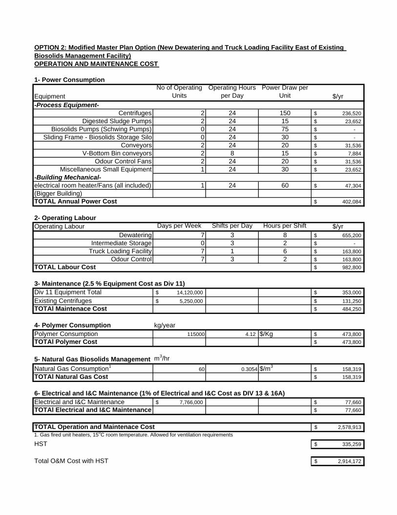
OPERATION AND MAINTENANCE COST
1- Power Consumption
EquipmentNo of Operating
UnitsOperating Hours
per DayPower Draw per
Unit $/yr-Process Equipment-
Centrifuges 2 24 150 236,520$
Digested Sludge Pumps 2 24 15 23,652$
Biosolids Pumps (Schwing Pumps) 0 24 75 -$
Sliding Frame - Biosolids Storage Silo 0 24 30 -$
Conveyors 2 24 20 31,536$
V-Bottom Bin conveyors 2 8 15 7,884$
Odour Control Fans 2 24 20 31,536$
Miscellaneous Small Equipment 1 24 30 23,652$
-Building Mechanical-electrical room heater/Fans (all included) 1 24 60 47,304$
(Bigger Building)TOTAL Annual Power Cost 402,084$
2- Operating Labour Operating Labour Days per Week Shifts per Day Hours per Shift $/yr
Dewatering 7 3 8 655,200$
Intermediate Storage 0 3 2 -$
Truck Loading Facility 7 1 6 163,800$
Odour Control 7 3 2 163,800$
TOTAL Labour Cost 982,800$
3- Maintenance (2.5 % Equipment Cost as Div 11)Div 11 Equipment Total 14,120,000$ 353,000$
Existing Centrifuges 5,250,000$ 131,250$
TOTAl Maintenace Cost 484,250$
4- Polymer Consumption kg/yearPolymer Consumption 115000 4.12 $/Kg 473,800$
TOTAl Polymer Cost 473,800$
5- Natural Gas Biosolids Management Am3/hr
Natural Gas Consumption160 0.3054 $/m3
158,319$
TOTAl Natural Gas Cost 158,319$
6- Electrical and I&C Maintenance (1% of Electrical and I&C Cost as DIV 13 & 16A)Electrical and I&C Maintenance 7,766,000$ 77,660$
TOTAl Electrical and I&C Maintenance 77,660$
TOTAL Operation and Maintenace Cost 2,578,913$
1. Gas fired unit heaters, 15oC room temperature. Allowed for ventilation requirements
HST 335,259$
Total O&M Cost with HST 2,914,172$
OPTION 2: Modified Master Plan Option (New Dewatering and Truck Loading Facility East of Existing Biosolids Management Facility)

Appendix 5 Option 3 Drawings


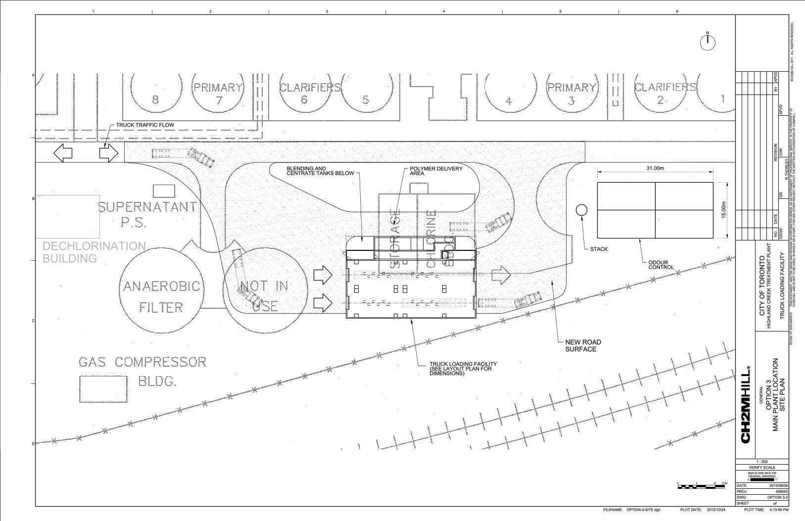

Appendix 6 Option 3 Cost Estimate

Option 3
Component Description Quantity Unit Unit Cost Material Cost Total Cost
% of Matl Cost
Div 1 - General Requirements
General Requirements- Covers the general contractor's site cost such as office trailer, site staff, small tools and equipment, permits, cleanup, testing & start-up.
Included in General Conditions Below
Sub-Total Division 1 - General Requirements -$
Div 2 - Building Sitework
Civil Work (Widenning the main plant road and
structural support of tunnel) 1 sum 2,000,000.00$ -$ -$ incl 2,000,000$ Demolition (Old Chlorine Building and Anaerobic
Filter and east Tank of Anaerobic Filter) 1 sum 5,000,000.00$ -$ -$ incl 5,000,000$ Tie -In Allowances(Centrate to Old Influent
Headwork Pipe area and Digested Biosolids to
Truck Loading Facility) 1 sum 150,000.00$ -$ -$ incl 150,000$
Sub-Total Division 2 - Building Sitework 7,150,000$
Div 3 - Concrete
Building - (Architectural, Structural) 8,634 m21,620.00$ 13,987,080.00$ -$ incl 13,987,080$
New Centrate and Blending Tanks 2,000,000.00$ -$ incl 2,000,000$
Sub-Total Division 3 - Concrete 15,987,100$
Div 4 - Masonry
Stack 1 sum 1,000,000.00$ -$ -$ Incl. 1,000,000$
Sub-Total Division 4 - Masonry 1,000,000$
Div 5 - Metals
Metals - INCLUDED IN DIV 3 -$
Sub-Total Division 5 - Metals -$
Div 6 - Wood & Plastics
Wood and Plastics- INCLUDED IN DIV 3 -$
Sub-Total Division 6 - Wood & Plastics -$
Div 7 - Thermal and Moisture ProtectionThermal and Moisture Protection- INCLUDED IN DIV 3 -$
Sub-Total Division 7 - Thermal and Moisture Protection
-$
Div 8 - Doors and Windows
Doors and Windows- INCLUDED IN DIV 3 -$
Sub-Total Division 8 - Doors and Windows -$
Div 9 - Finishes
Finishes- INCLUDED IN DIV 3 -$
Sub-Total Division 9 - Finishes -$
Div 10 - Specialties
Specialties- INCLUDED IN DIV 3 -$
Sub-Total Division 10 - Specialties -$
Div 11 - Equipment
-Truck Loading Facility Equipment
Distribution Conveyors 2 each 100,000.00$ 200,000$ 50% 100,000$ 300,000$
Conveyors-top of v-bottom bins 4 each 70,000.00$ 280,000$ 50% 140,000$ 420,000$
V-Bottom Bins Storage (5.5 days) 4 package 4,000,000$ -$ 30% 1,200,000 5,200,000$
Weight Scales 8 each 200,000.00$ 1,600,000$ 50% 800,000$ 2,400,000$
-Odour Control Facility Equipment
Odour Control Biofilter 1 package 1,300,000.00$ 1,300,000$ 50% 650,000$ 1,950,000$
-Dewatering Equipment
Polymer Makeup System 1 sum 1,000,000$ 1,000,000$ 50% 500,000$ 1,500,000$
Sludge Pumps 5 each 60,000.00$ 300,000$ 50% 150,000$ 450,000$ Dewatering Centrifuges (Relocating Existing Centrifuges ) -$ -$ 1,750,000$ 1,750,000$
Dewatered Sludge Classifying Conveyors 5 each 20,000.00$ 100,000$ 50% 50,000$ 150,000$
Sub-Total Division 11 - Equipment 14,120,000$
Biosolids Master Plan Option with New Centrifuges located at Main Plant(East of Dechlorination Building) -
OPTION 3Cost Estimate(1)
Installation
01-Option3-Rev1 - carbonsteelvbins.xls - option31 of 2 11/5/2012

Option 3
Component Description Quantity Unit Unit Cost Material Cost Total Cost
% of Matl Cost
Biosolids Master Plan Option with New Centrifuges located at Main Plant(East of Dechlorination Building) -
OPTION 3Cost Estimate(1)
Installation
Div 13 - Special Construction I&C
Instrument Control Panel (ICP), PLC System - Software and Hardware 1 sum 3,530,000.00$ -$ -$ Incl. 3,530,000$
-Estimated as 25% of Equipment cost(DIV 11)
Sub-Total Division 13 - Special Construction I&C
3,530,000$
Div 14 Conveyance System
Monorail/Bridge Crain 1 sum 300,000.00$ -$ -$ Incl. 300,000$
Sub-Total Division 14 - Conveying Systems 300,000$
Div 15A - Building Mechanical
Exhaust Fans/ Heaters 1 sum 550,000$ -$ -$ Incl 550,000$
sump pump allowances 1 sum 150,000$ -$ -$ Incl 150,000$
Make Up Air Units/Dehumidication Units 1 sum 1,500,000$ -$ -$ Incl 1,500,000$
Duct Work 1 sum 900,000$ -$ -$ Incl 900,000$
Sub-Total Division 15A - Building Mechanical 3,100,000$
Div 15B - Process Mechanical
5(300 mm sst pipe) 100 m run 1 sum 200,000.00$ -$ -$ Incl 200,000$
2(450 mm ) Centrate Pipes 1 sum 100,000.00$ -$ -$ Incl 100,000$
250 knife valves & Actuators 16 each 30,000.00$ 480,000$ 50% 240,000$ 720,000$
Miscellaneous Piping 1 sum 100,000$ 100,000$ 50% 50,000$ 150,000$
Sub-Total Division 15B - Process Mechanical 1,170,000$
Div 16A - Electrical
Electrical - Supply and Install 1 sum 4,236,000.00$ -$ -$ Incl. 4,236,000$
-Estimated as 30% of Equipment Cost (DIV 11)
Sub-Total Division 16A - Electrical 4,236,000$
Sub-Total Basic Facility Costs (A1) 50,593,100$
Indirect Cost
Contract Staff & Home Office OH 8.00% 4,047,448$
Subtotal 54,640,548$
General Conditions 7.00% 3,824,838$
Subtotal 58,465,386$
Mobilization/Demobilization 2.00% 1,169,308$
Insurance 1.00% 584,654$
Bond 1.00% 584,654$
Subtotal 60,804,002$
Profit 5.00% 3,040,200$
Subtotal 63,844,202$
Subtotal Indirect Cost 13,251,102$
Contingency 30.00% 19,153,261$
Subtotal 82,997,462$
Escalation to Mid-point of Construction (2016) 9.74% 8,083,953$
Total Construction Cost (Excluding Engineering and HST) 91,081,415$
Engineering Cost (12% of Total Construction Cost) 12% 10,929,770$
HST 13% 11,840,584$
Total Estimated Capital Cost, Includign Construction, Engineering and Excluding HST 102,011,185$
Total Estimated Capital Cost, Including HST 113,851,769$ (1) The Cost Estimate have been prepared for guidance in project evaluation and implementation from the information available at the time the estimate was prepared. These estimates are considered Order of Magnitude Estimates by the American Association of
Cost Engineers (AACE). This level of estimate is expected to be accuate to within plus 50% to minus 30% of the costs prepared.
01-Option3-Rev1 - carbonsteelvbins.xls - option32 of 2 11/5/2012

OPERATION AND MAINTENANCE COST
1- Power Consumption
EquipmentNo of Operating
UnitsOperating Hours
per DayPower Draw per
Unit $/yr-Process Equipment-
Centrifuges 2 24 150 236,520$
Digested Sludge Pumps 2 24 15 23,652$
Biosolids Pumps (Schwing Pumps) 0 24 75 -$
Sliding Frame - Biosolids Storage Silo 0 24 30 -$
Conveyors 2 24 20 31,536$
V-Bottom Bin conveyors 2 8 15 7,884$
Odour Control Fans 2 24 20 31,536$
Miscellaneous Small Equipment 1 24 30 23,652$
-Building Mechanical-electrical room heater/Fans (all included) 1 24 60 47,304$
(Bigger Building)TOTAL Annual Power Cost 402,084$
2- Operating Labour Operating Labour Days per Week Shifts per Day Hours per Shift $/yr
Dewatering 7 3 8 655,200$
Intermediate Storage 0 3 2 -$
Truck Loading Facility 7 1 6 163,800$
Odour Control 7 3 2 163,800$
TOTAL Labour Cost 982,800$
3- Maintenance (2.5 % Equipment Cost as Div 11)Div 11 Equipment Total 14,120,000$ 353,000$
Existing Centrifuges 5,250,000$ 131,250$
TOTAl Maintenace Cost 484,250$
4- Polymer Consumption kg/yearPolymer Consumption 115000 4.12 $/Kg 473,800$
TOTAl Polymer Cost 473,800$
5- Natural Gas Biosolids Management Area
Natural Gas Consumption160$ 0.3054 $/m3
158,319$
(158,319)$
TOTAl Natural Gas Cost -$
6- Electrical and I&C Maintenance (1% of Electrical and I&C Cost as DIV 13 & 16A)Electrical and I&C Maintenance 7,766,000$ 77,660$
TOTAl Electrical and I&C Maintenance 77,660$
TOTAL Operation and Maintenace Cost 2,420,594$
1. Gas fired unit heaters, 15oC room temperature. Allowed for ventilation requirements
HST 314,677$
Total O&M Cost with HST 2,735,271$
OPTION 3: BIOSOLIDS MASTER PLAN OPTION NEW CENTRIFUGES LOCATED AT MAIN PLANT(East of Dechlorination Building)
Credit for not servicing current Biosolids Building

Appendix 7 Option 4 Drawings


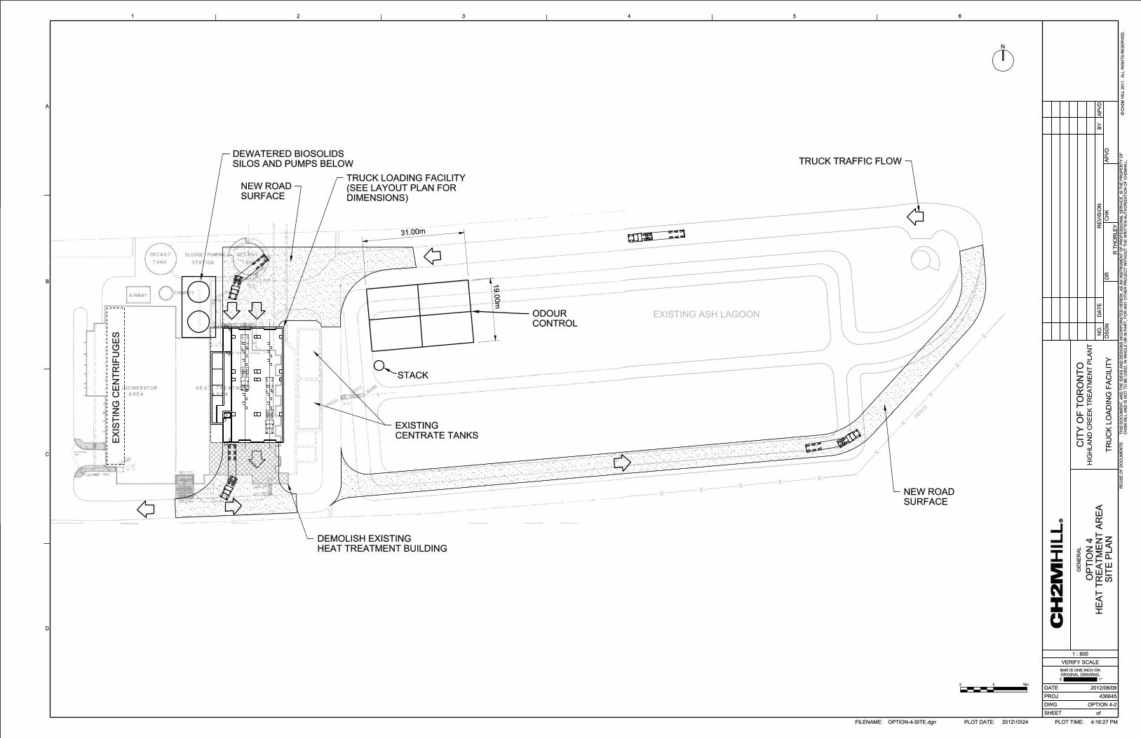

Appendix 8 Option 4 Cost Estimate
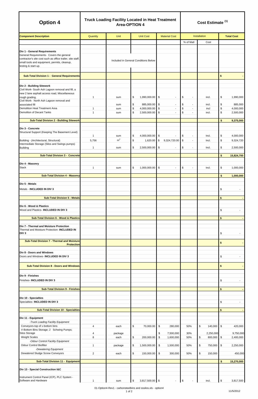
Option 4
Component Description Quantity Unit Unit Cost Material Cost Total Cost
% of Matl Cost
Div 1 - General Requirements
General Requirements- Covers the general contractor's site cost such as office trailer, site staff, small tools and equipment, permits, cleanup, testing & start-up.
Included in General Conditions Below
Sub-Total Division 1 - General Requirements -$
Div 2 - Building Sitework
Civil Work- South Ash Lagoon removal and fill, a
new 2 lane asphalt access road, Miscellaneous
rough grading. 1 sum 1,990,000.00$ -$ -$ incl. 1,990,000$ Civil Work- North Ash Lagoon removal and
associated fill sum 885,000.00$ -$ -$ incl. 885,000$
Demolition Heat Treatment Area 1 sum 4,000,000.00$ -$ -$ incl 4,000,000$
Demoliton of Decant Tanks 1 sum 2,500,000.00$ -$ -$ incl. 2,500,000$
Sub-Total Division 2 - Building Sitework 9,375,000$
Div 3 - Concrete
Structural Support (Keeping The Basement Level)1 sum 4,000,000.00$ -$ -$ Incl. 4,000,000$
Building - (Architectural, Structural) 5,756 m21,620.00$ 9,324,720.00$ -$ Incl. 9,324,720$
Intermediate Storage (Silos and Swings pumps)
Building 1 sum 2,500,000.00$ -$ -$ Incl. 2,500,000$
Sub-Total Division 3 - Concrete 15,824,700$
Div 4 - Masonry
Stack 1 sum 1,000,000.00$ -$ -$ Incl. 1,000,000$
Sub-Total Division 4 - Masonry 1,000,000$
Div 5 - Metals
Metals - INCLUDED IN DIV 3 -$
Sub-Total Division 5 - Metals -$
Div 6 - Wood & Plastics
Wood and Plastics- INCLUDED IN DIV 3 -$
Sub-Total Division 6 - Wood & Plastics -$
Div 7 - Thermal and Moisture ProtectionThermal and Moisture Protection- INCLUDED IN DIV 3 -$
Sub-Total Division 7 - Thermal and Moisture Protection
-$
Div 8 - Doors and Windows
Doors and Windows- INCLUDED IN DIV 3 -$
Sub-Total Division 8 - Doors and Windows -$
Div 9 - Finishes
Finishes- INCLUDED IN DIV 3 -$
Sub-Total Division 9 - Finishes -$
Div 10 - Specialties
Specialties- INCLUDED IN DIV 3 -$
Sub-Total Division 10 - Specialties -$
Div 11 - Equipment
-Truck Loading Facility Equipment
Conveyors-top of v-bottom bins 4 each 70,000.00$ 280,000$ 50% 140,000$ 420,000$ V-Bottom Bins Storage; 2 Schwing Pumps; Silos Storage 4 package 7,500,000$ 30% 2,250,000 9,750,000
Weight Scales 8 each 200,000.00$ 1,600,000$ 50% 800,000$ 2,400,000$
-Odour Control Facility Equipment
Odour Control Biofilter 1 package 1,500,000.00$ 1,500,000$ 50% 750,000$ 2,250,000$
-Dewatering Equipment
Dewatered Sludge Screw Conveyors 2 each 150,000.00$ 300,000$ 50% 150,000$ 450,000
Sub-Total Division 11 - Equipment 15,270,000$
Div 13 - Special Construction I&C
Instrument Control Panel (ICP), PLC System - Software and Hardware 1 sum 3,817,500.00$ -$ -$ incl. 3,817,500$
Truck Loading Facility Located in Heat Treatment Area-OPTION 4 Cost Estimate (1)
Installation
01-Option4-Rev1 - carbonsteelbins and sssilos.xls - option41 of 2 11/5/2012

Option 4
Component Description Quantity Unit Unit Cost Material Cost Total Cost
% of Matl Cost
Truck Loading Facility Located in Heat Treatment Area-OPTION 4 Cost Estimate (1)
Installation
-Estimated as 25% of Equipment cost(DIV 11)
Sub-Total Division 13 - Special Construction I&C
3,817,500$
Div 14 - Conveying Systems
Bridge Crane for Schwing Pump 1 sum 150,000.00$ -$ -$ Incl. 150,000$
Sub-Total Division 14 - Conveying Systems 150,000$
Div 15A - Building Mechanical
Exhaust Fans/ Heaters 1 sum 450,000$ -$ -$ Incl 450,000$
sump pump allowances 1 sum 150,000$ -$ -$ Incl 150,000$
Make Up Air Units/Dehumidication Units 1 sum 1,500,000$ -$ -$ Incl 1,500,000$
Duct Work 1 sum 750,000$ -$ -$ Incl 750,000$
Sub-Total Division 15A - Building Mechanical 2,850,000$
Div 15B, Process Mechanical
4(300 mm sst pipe)Biosolids Pumps to v-Bottom Bins pipes 1 sum 200,000$ -$ -$ Incl 200,000$
250 knife valves & Actuators 16 each 30,000.00$ 480,000$ 50% 240,000$ 720,000$
High Pressure Ball Valves valves- 600 psi 4 each 30,000.00$ 120,000$ 50% 60,000$ 180,000$
Miscellaneous Piping 1 sum 100,000.00$ -$ -$ Incl 100,000$
Sub-Total Division 15B - Process Mechanical 1,200,000$
Div 16A - Electrical
Electrical - Supply and Install 1 sum 4,581,000.00$ -$ -$ Incl. 4,581,000$
-Estimated as 30% of Equipment Cost (DIV 11)
Sub-Total Division 16A - Electrical 4,581,000$
Sub-Total Basic Facility Costs (Direct Cost) 54,068,200$
Indirect Cost
Contract Staff & Home Office OH 8.00% 4,325,456$
Subtotal 58,393,656$
General Conditions 7.00% 4,087,556$
Subtotal 62,481,212$
Mobilization/Demobilization 2.00% 1,249,624$
Insurance 1.00% 624,812$
Bond 1.00% 624,812$
Subtotal 64,980,460$
Profit 5.00% 3,249,023$
Subtotal 68,229,483$
Subtotal Indirect Cost 14,161,283$
Contingency 30.00% 20,468,845$
Subtotal 88,698,328$
Escalation to Mid-point of Construction (2016) 9.74% 8,639,217$
Total Construction Cost (Excluding Engineering and HST) 97,337,546$
Engineering Cost (12% of Total Construction Cost) 12% 11,680,505$
HST 13% 12,653,881$
Total Estimated Capital Cost, Including Construction, Engineering and Excluding HST 109,018,051$
Total Estimated Capital Cost, Including HST 121,671,932$ (1) The Cost Estimate have been prepared for guidance in project evaluation and implementation from the information available at the time the estimate was prepared. These estimates are considered Order of Magnitude Estimates by the American Association of
Cost Engineers (AACE). This level of estimate is expected to be accuate to within plus 50% to minus 30% of the costs prepared.
01-Option4-Rev1 - carbonsteelbins and sssilos.xls - option42 of 2 11/5/2012

OPTION 4: TRUCK LOADING FACILITY LOCATED IN HEAT TREATMENT AREAOPERATION AND MAINTENANCE COST
1- Power Consumption
EquipmentNo of Operating
UnitsOperating Hours
per DayPower Draw per
Unit $/yr-Process Equipment-
Centrifuges 2 24 150 236,520$
Digested Sludge Pumps 2 24 15 23,652$
Biosolids Pumps (Schwing Pumps) 1 24 75 59,130$
Sliding Frame - Biosolids Storage Silo 1 24 30 23,652$
Conveyors 2 24 20 31,536$
V-Bottom Bin conveyors 2 8 15 7,884$
Odour Control Fans 2 24 20 31,536$
Miscellaneous Small Equipment 1 24 30 23,652$
-Building Mechanical-electrical room heater/Fans (all included) 1 24 50 39,420$
(Smaller Building)TOTAL Annual Power Cost 476,982$
2- Operating Labour Operating Labour Days per Week Shifts per Day Hours per Shift $/yr
Dewatering 7 3 8 655,200$
Intermediate Storage 7 3 2 163,800$
Truck Loading Facility 7 1 6 163,800$
Odour Control 7 3 2 163,800$
TOTAL Labour Cost 1,146,600$
3- Maintenance (2.5 % Equipment Cost as Div 11)Div 11 Equipment Total 15,270,000$ 381,750$
Existing Centrifuges 5,250,000$ 131,250$
TOTAl Maintenace Cost 513,000$
4- Polymer Consumption kgPolymer Consumption 115000 4.12 $/Kg 473,800$
TOTAl Polymer Cost 473,800$
5- Natural Gas Biosolids Management m3/hr
Natural Gas Consumption140$ 0.3054 $/m3
105,546$
TOTAl Natural Gas Cost 105,546$
6- Electrical and I&C Maintenance (1% of Electrical and I&C Cost as DIV 13 & 16A)Electrical and I&C Maintenance 8,398,500$ 83,985$
TOTAl Electrical and I&C Maintenance 83,985$
TOTAL Operation and Maintenace Cost 2,799,913$
1. Gas fired unit heaters, 15 oC room temperature. Allowed for ventilation requirements.
HST 363,989$
Total O&M Cost with HST 3,163,902$
Appendix 9 Summary of Life Cycle Cost Estimate
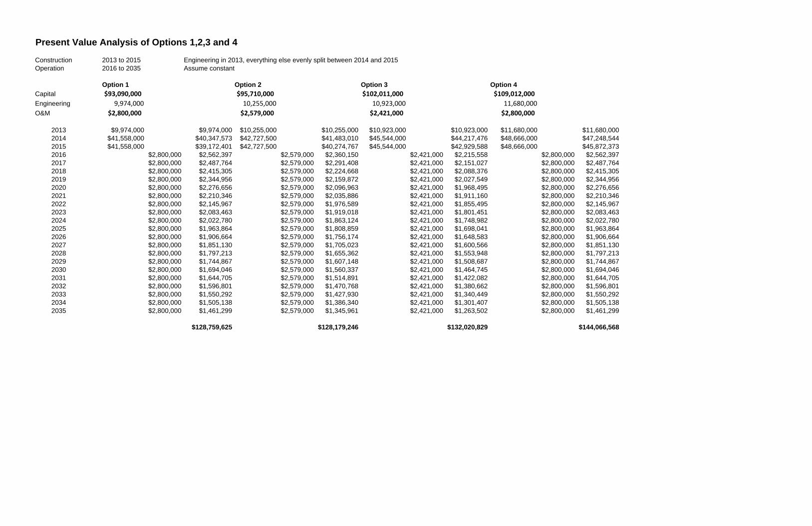
Present Value Analysis of Options 1,2,3 and 4
Construction 2013 to 2015 Engineering in 2013, everything else evenly split between 2014 and 2015Operation 2016 to 2035 Assume constant
Option 1 Option 2 Option 3 Option 4Capital $93,090,000 $95,710,000 $102,011,000 $109,012,000
Engineering 9,974,000 10,255,000 10,923,000 11,680,000
O&M $2,800,000 $2,579,000 $2,421,000 $2,800,000
2013 $9,974,000 $9,974,000 $10,255,000 $10,255,000 $10,923,000 $10,923,000 $11,680,000 $11,680,0002014 $41,558,000 $40,347,573 $42,727,500 $41,483,010 $45,544,000 $44,217,476 $48,666,000 $47,248,5442015 $41,558,000 $39,172,401 $42,727,500 $40,274,767 $45,544,000 $42,929,588 $48,666,000 $45,872,3732016 $2,800,000 $2,562,397 $2,579,000 $2,360,150 $2,421,000 $2,215,558 $2,800,000 $2,562,3972017 $2,800,000 $2,487,764 $2,579,000 $2,291,408 $2,421,000 $2,151,027 $2,800,000 $2,487,7642018 $2,800,000 $2,415,305 $2,579,000 $2,224,668 $2,421,000 $2,088,376 $2,800,000 $2,415,3052019 $2,800,000 $2,344,956 $2,579,000 $2,159,872 $2,421,000 $2,027,549 $2,800,000 $2,344,9562020 $2,800,000 $2,276,656 $2,579,000 $2,096,963 $2,421,000 $1,968,495 $2,800,000 $2,276,6562021 $2,800,000 $2,210,346 $2,579,000 $2,035,886 $2,421,000 $1,911,160 $2,800,000 $2,210,3462022 $2,800,000 $2,145,967 $2,579,000 $1,976,589 $2,421,000 $1,855,495 $2,800,000 $2,145,9672023 $2,800,000 $2,083,463 $2,579,000 $1,919,018 $2,421,000 $1,801,451 $2,800,000 $2,083,4632024 $2,800,000 $2,022,780 $2,579,000 $1,863,124 $2,421,000 $1,748,982 $2,800,000 $2,022,7802025 $2,800,000 $1,963,864 $2,579,000 $1,808,859 $2,421,000 $1,698,041 $2,800,000 $1,963,8642026 $2,800,000 $1,906,664 $2,579,000 $1,756,174 $2,421,000 $1,648,583 $2,800,000 $1,906,6642027 $2,800,000 $1,851,130 $2,579,000 $1,705,023 $2,421,000 $1,600,566 $2,800,000 $1,851,1302028 $2,800,000 $1,797,213 $2,579,000 $1,655,362 $2,421,000 $1,553,948 $2,800,000 $1,797,2132029 $2,800,000 $1,744,867 $2,579,000 $1,607,148 $2,421,000 $1,508,687 $2,800,000 $1,744,8672030 $2,800,000 $1,694,046 $2,579,000 $1,560,337 $2,421,000 $1,464,745 $2,800,000 $1,694,0462031 $2,800,000 $1,644,705 $2,579,000 $1,514,891 $2,421,000 $1,422,082 $2,800,000 $1,644,7052032 $2,800,000 $1,596,801 $2,579,000 $1,470,768 $2,421,000 $1,380,662 $2,800,000 $1,596,8012033 $2,800,000 $1,550,292 $2,579,000 $1,427,930 $2,421,000 $1,340,449 $2,800,000 $1,550,2922034 $2,800,000 $1,505,138 $2,579,000 $1,386,340 $2,421,000 $1,301,407 $2,800,000 $1,505,1382035 $2,800,000 $1,461,299 $2,579,000 $1,345,961 $2,421,000 $1,263,502 $2,800,000 $1,461,299
$128,759,625 $128,179,246 $132,020,829 $144,066,568


