12/10/2013 GEOTECHNICAL MANUAL Appendix D. Drilled Shaft Report Example PLEASE NOTE A sample foundations report is included here for reference. It is provided as an example of content, format, and organization representative of a typical Foundation Investigation and Recommendation Report for a drilled shaft foundation. As site conditions vary widely, the investigation means and methods, and report content (including recommendations), may differ for other projects. Note that the selection and inclusion of this report as a sample does not imply that it is guaranteed to be free of errors. Please contact the Foundations Unit with any questions when interpreting a geotechnical report issued by this office or if you have any questions with respect to preparing geotechnical reports for MnDOT. The information presented here is intended for use as a resource by geotechnical engineering professionals. MnDOT makes no warranty as to the suitability of engineering reports in the style of this sample report, for other geotechnical needs, purposes, clients, or projects.
Transcript
12/10/2013 GEOTECHNICAL MANUAL
Appendix D. Drilled Shaft Report Example PLEASE NOTE A sample foundations report is included here for reference. It is provided as an example of content, format, and organization representative of a typical Foundation Investigation and Recommendation Report for a drilled shaft foundation. As site conditions vary widely, the investigation means and methods, and report content (including recommendations), may differ for other projects. Note that the selection and inclusion of this report as a sample does not imply that it is guaranteed to be free of errors. Please contact the Foundations Unit with any questions when interpreting a geotechnical report issued by this office or if you have any questions with respect to preparing geotechnical reports for MnDOT. The information presented here is intended for use as a resource by geotechnical engineering professionals. MnDOT makes no warranty as to the suitability of engineering reports in the style of this sample report, for other geotechnical needs, purposes, clients, or projects.
Minnesota Department of Transportation Office of Materials & Road ResearchGeotechnical Engineering Section Office (651) 366-5598 1400 Gervais Ave - Mailstop 645 Fax: (651) 366-5510 Maplewood, MN 55109
Date: October 02, 2008
To: D. Dorgan, State Bridge Engineer Office of Bridges & Structures
From: Hossana Teklyes, Grad Engineer-2 Foundations Unit
Concur: Gary Person, Foundations Engineer Foundations Unit
Concur: Rich Lamb, Foundations Project Engineer Foundations Unit
Subject: S.P. 3902-21 Bridge 39008 TH 11 over Rapid River in Clementson
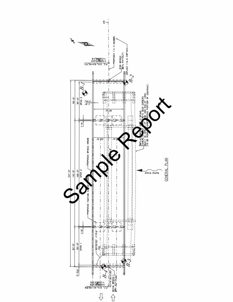
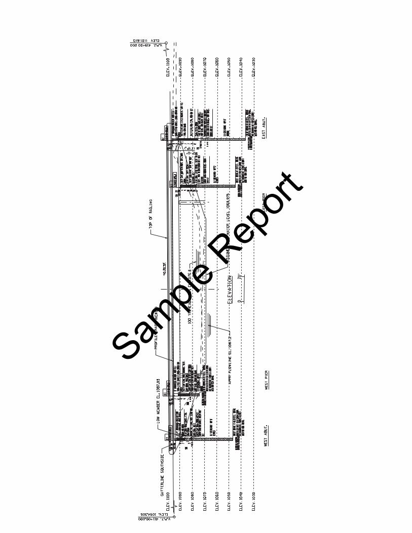
Project SummaryThis report provides for a preliminary foundation investigation, analysis and recommendations for replacing Bridge 5557 with Bridge 39008.The old three-span arch Bridge built in 1950, will be replaced with a new three-span structure. The new Bridge (39008) will use 63 inch prestressed concrete beams with a cast in place deck 40 feet wide by 247 feet long. The substructures are to be supported on drilled shaft foundations.
This report is preliminary in nature because of the iterative design process involved with drilled shaft foundations. A final report will be provided once the final structural loads (both axial and lateral) are determined. Load and Resistance Factor Design (LRFD) methods will be used for the analysis and design recommendations.
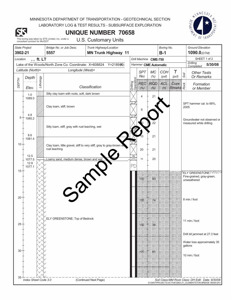
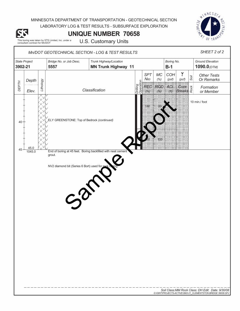
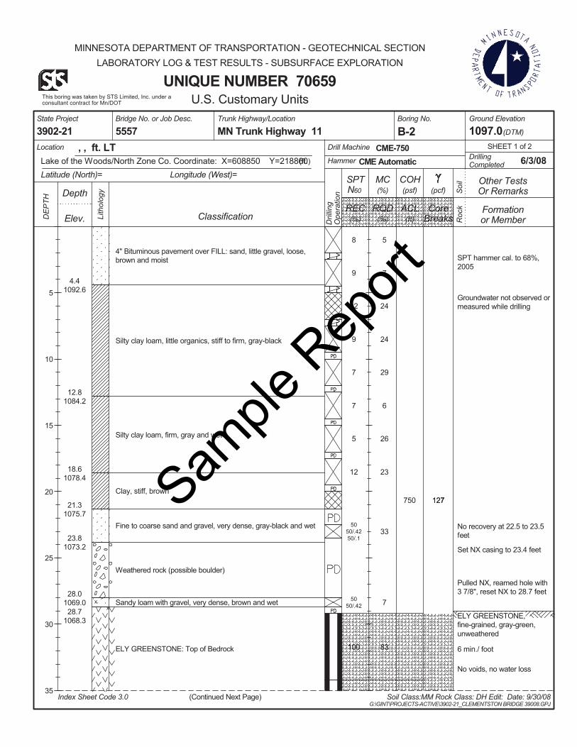
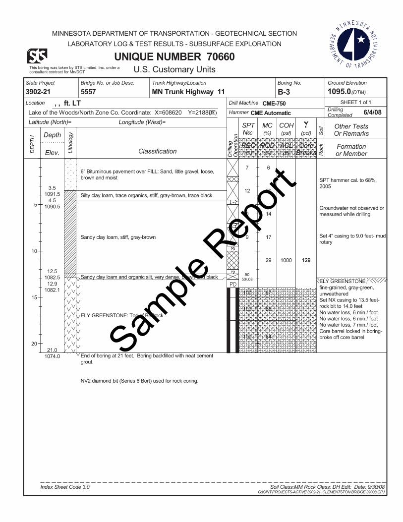
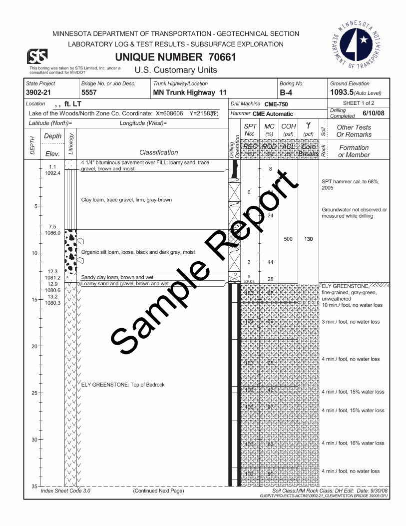
Field Investigation and Foundation ConditionsFour foundation borings were taken by STS, under a consultant contract for Mn/DOT, in June 2008. A copy of these borings is included with this report.
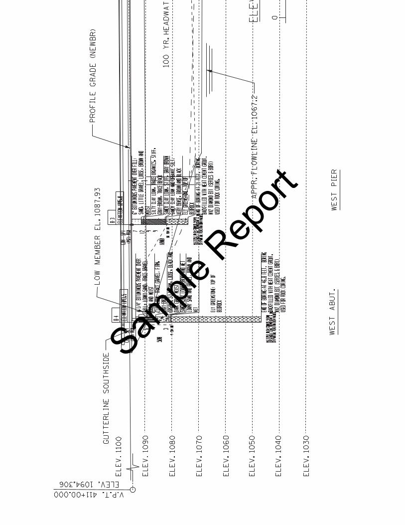
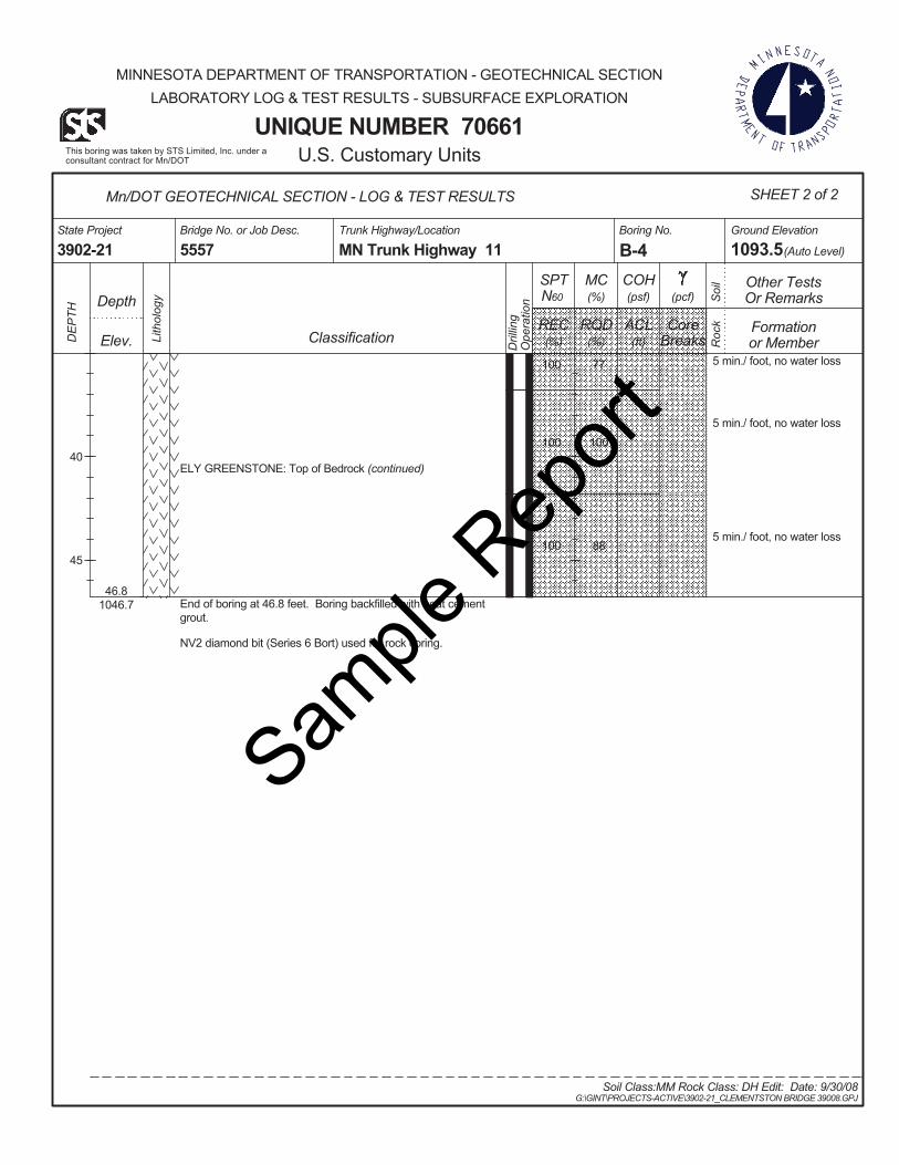
West Abutment & Pier At the proposed west Abutment & Pier the foundation soils consist of a 10-15 ft. layer of sandy clay loam soil followed by bedrock. The bedrock at this site is a greenstone generally fresh with slight weathering. Unconfined compression tests were performed on selected representative rock core samples in order to determine the unconfined compressive strength and elastic modulus of the rock. The results of these tests are plotted on the individual boring logs and are shown in Table 1.Groundwater was not encountered during drilling.
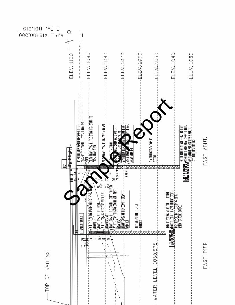
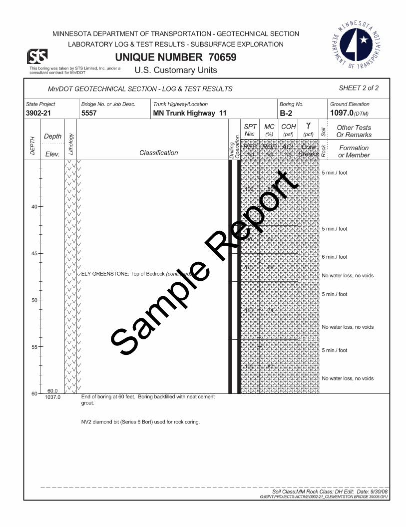
East Abutment & Pier At the proposed east Abutment & Pier the foundation soils consist of a 15-20 ft. layer of sandy loam soil followed by bedrock. The bedrock at this site is a greenstone generally fresh with slight weathering. Unconfined compressive tests were performed on selected representative rock core samples in order to determine the unconfined compressive strength and elastic modulus of the rock. The results of these tests
Digitallysigned by HossanaTeklyes
Digitallysignedby Gary Person
Sample
Rep
ort
SP 3902-21 Bridge 39008 Preliminary Foundation Investigation and Recommendations October 02, 2008
Page 2 of 9
are plotted on the individual boring logs and are shown in Table 1. Groundwater was not encountered during drilling.
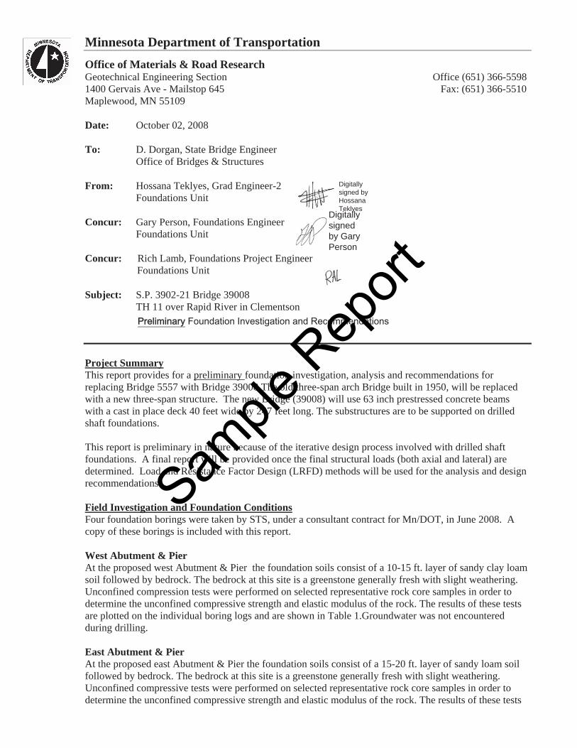
West Abutment Samples Fig 1: Rock Core from 28.1 ft. to 28.4 ft. Fig 2: Rock Core from 40 ft. to 40.3 ft
East Abutment Samples Fig 3: Rock core from 18.2 ft. to 18.5 ft. Fig 4: Rock core from 26 ft. to 26.8 ft.
Sample
Rep
ort
SP 3902-21 Bridge 39008 Preliminary Foundation Investigation and Recommendations October 02, 2008
Page 3 of 9
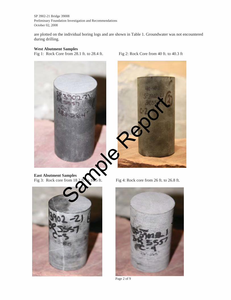
Table 1: Results of Lab Tests on Rock Core Samples Boring Elevation Rock Description qu
B-3 897.7 Greenstone, slightly weathered to generally fresh
9,000** 1,825,400
B-4 899.1 Greenstone, slightly weathered to generally fresh
30,000* 3,438,500
* The rock core did not reach unconfined compressive strength ** The rock core did reach unconfined compressive strength
Please refer to the attached boring logs for a detailed description of the foundation soils and rock. Rock core is available for inspection in our lab. Please contact our office if you wish to see the core.
Foundation AnalysisLocations and elevations of existing and proposed substructures were determined from a bridge survey and a preliminary bridge plan provided by the Bridge Office. The existing three- span arch bridge was constructed in 1950 and is supported on spread footing foundations on the shallow bedrock.
Fig 5.The existing three-span arch Bridge (5557) crossing Rapid River in Clementson
ScourAt this site, no scour depth has been predicted by the Hydraulics Section.
Sample
Rep
ort
SP 3902-21 Bridge 39008 Preliminary Foundation Investigation and Recommendations October 02, 2008
Page 4 of 9
Drilled shaft Settlement For footings bearing on fair to very good rock, according to the Geomechanics Classification system, as defined in Article 10.4.6.4(AASHTO LRFD Bridge Design Specifications,2008 Interim Revisions), elastic settlements may generally be assumed to be less than 0.5 in.
Lateral loads are not expected to control the drilled shaft design for this project. However, the lateral deflection will be checked once the final structural loads are made available.
The construction method to install the drilled shaft foundations is expected to utilize temporary casing and drilling slurry (water). The casing will first be sealed into competent rock and then the shaft will be drilled out to the design depth. Before placing the rebar cage, the bottom of the shaft will be cleaned out thoroughly.
Abutment & Pier Foundations – Drilled Shaft Axial Capacity Since bedrock was found at a shallow depth during boring at the abutment and pier locations, drilled shafts foundation were analyzed. Diameters of 36, 42 and 48 in. were assumed for the drilled shaft.
The drilled shaft design follows the guidelines presented in the AASHTO LRFD BRIDGE DESIGN (2008 Interim Revisions). Because of the complexities and unknowns involved with load transfer in stratified rock, a conservative approach was used for design of the axial capacity of the shafts. This design assumes that the axial load will be resisted entirely by side resistance. In actual practice, some of the axial load is transferred to the base of the shaft, however, in lieu of static load testing, it is very difficult to determine how much.
The unit side resistance was first calculated for each material layer using the analysis method of Kulhawy and Phoon (1993).
rockiningjoforaccounttoactorreductionf
rockofstrengthecompressivunconfinedq
pressurecatmospheripwhere
p
qpf
ui
a
a
ui
ai
int
65.0max
The total side resistance, Rs, was then computed using the following equation:
55.01
max s
n
iiisS wherefzBR
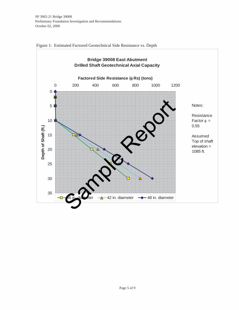
Because the final axial and lateral loads are unknown at this time, the factored side resistance is presented as a function of drilled shaft depth and diameter. The Structural Engineer should use this chart to select a preferred shaft diameter and depth and verify that the factored loads, iQi, from the most critical design case (strength or extreme event), meet or exceed the factored resistances for the options shown.
Sample
Rep
ort
SP 3902-21 Bridge 39008 Preliminary Foundation Investigation and Recommendations October 02, 2008
Page 5 of 9
Figure 1: Estimated Factored Geotechnical Side Resistance vs. Depth
Bridge 39008 East AbutmentDrilled Shaft Geotechnical Axial Capacity
0
5
10
15
20
25
30
35
0 200 400 600 800 1000 1200
Factored Side Resistance ( Rs) (tons)
Dep
th o
f Sha
ft (ft
.)
36 in. diameter 42 in. diameter 48 in. diameter
Notes:
Resistance Factor = 0.55
Assumed Top of shaft elevation = 1085 ft.
Sample
Rep
ort
SP 3902-21 Bridge 39008 Preliminary Foundation Investigation and Recommendations October 02, 2008
Page 6 of 9
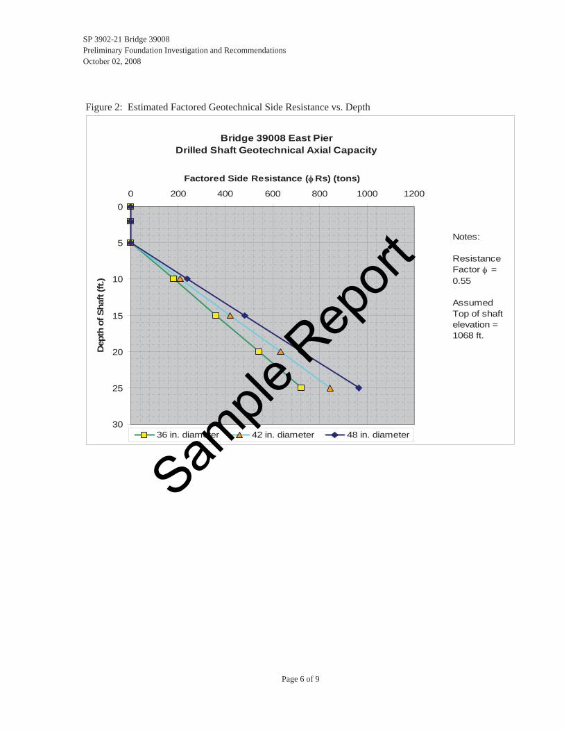
Figure 2: Estimated Factored Geotechnical Side Resistance vs. Depth
Bridge 39008 East PierDrilled Shaft Geotechnical Axial Capacity
0
5
10
15
20
25
30
0 200 400 600 800 1000 1200
Factored Side Resistance ( Rs) (tons)
Dep
th o
f Sha
ft (ft
.)
36 in. diameter 42 in. diameter 48 in. diameter
Notes:
Resistance Factor = 0.55
Assumed Top of shaft elevation = 1068 ft.
Sample
Rep
ort
SP 3902-21 Bridge 39008 Preliminary Foundation Investigation and Recommendations October 02, 2008
Page 7 of 9
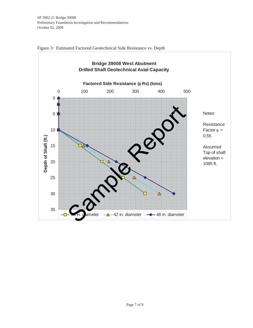
Figure 3: Estimated Factored Geotechnical Side Resistance vs. Depth
Bridge 39008 West AbutmentDrilled Shaft Geotechnical Axial Capacity
0
5
10
15
20
25
30
35
0 100 200 300 400 500
Factored Side Resistance ( Rs) (tons)
Dep
th o
f Sha
ft (ft
.)
36 in. diameter 42 in. diameter 48 in. diameter
Notes:
Resistance Factor = 0.55
Assumed Top of shaft elevation = 1085 ft.
Sample
Rep
ort
SP 3902-21 Bridge 39008 Preliminary Foundation Investigation and Recommendations October 02, 2008
Page 8 of 9
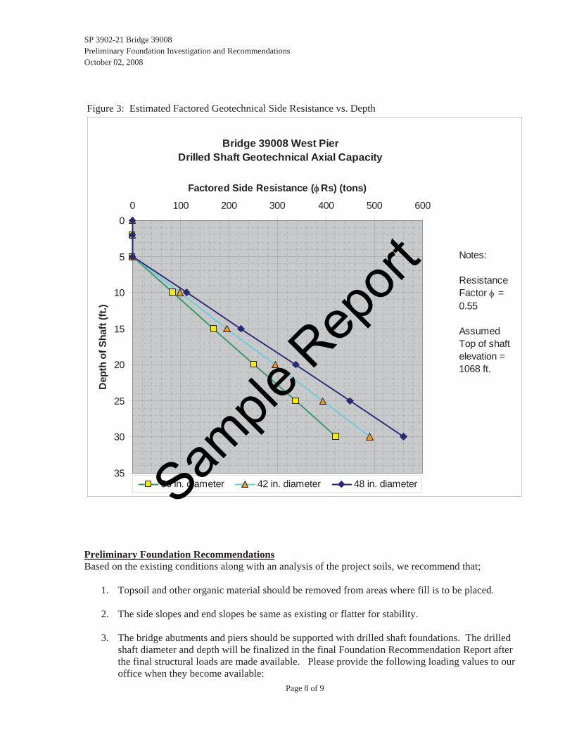
Figure 3: Estimated Factored Geotechnical Side Resistance vs. Depth
Bridge 39008 West PierDrilled Shaft Geotechnical Axial Capacity
0
5
10
15
20
25
30
35
0 100 200 300 400 500 600
Factored Side Resistance ( Rs) (tons)
Dep
th o
f Sha
ft (ft
.)
36 in. diameter 42 in. diameter 48 in. diameter
Notes:
Resistance Factor = 0.55
Assumed Top of shaft elevation = 1068 ft.
Preliminary Foundation RecommendationsBased on the existing conditions along with an analysis of the project soils, we recommend that;
1. Topsoil and other organic material should be removed from areas where fill is to be placed.
2. The side slopes and end slopes be same as existing or flatter for stability.
3. The bridge abutments and piers should be supported with drilled shaft foundations. The drilled shaft diameter and depth will be finalized in the final Foundation Recommendation Report after the final structural loads are made available. Please provide the following loading values to our office when they become available:
Sample
Rep
ort
SP 3902-21 Bridge 39008 Preliminary Foundation Investigation and Recommendations October 02, 2008
Page 9 of 9
a. Axial design load per column for most critical design case (strength or extreme event) b. Lateral design load per column for most critical design case (strength or extreme event)
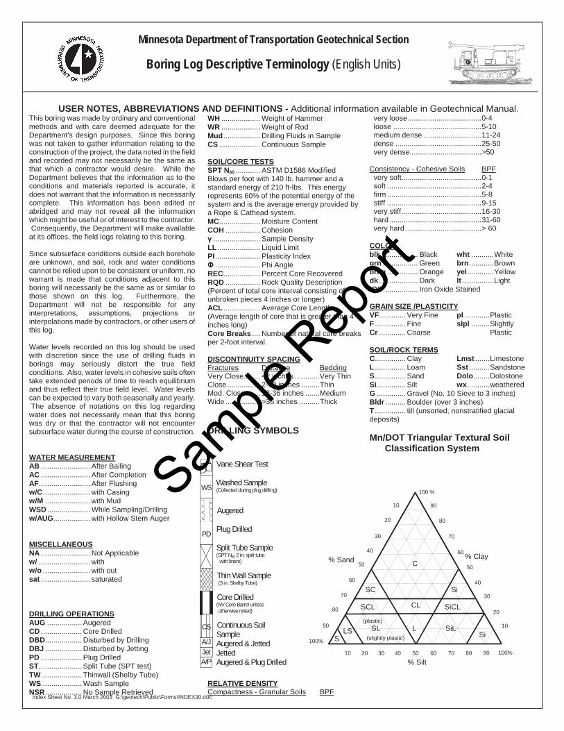
USER NOTES, ABBREVIATIONS AND DEFINITIONS - Additional information available in Geotechnical Manual. This boring was made by ordinary and conventional methods and with care deemed adequate for the Department's design purposes. Since this boring was not taken to gather information relating to the construction of the project, the data noted in the field and recorded may not necessarily be the same as that which a contractor would desire. While the Department believes that the information as to the conditions and materials reported is accurate, it does not warrant that the information is necessarily complete. This information has been edited or abridged and may not reveal all the information which might be useful or of interest to the contractor. Consequently, the Department will make available at its offices, the field logs relating to this boring.
Since subsurface conditions outside each borehole are unknown, and soil, rock and water conditions cannot be relied upon to be consistent or uniform, no warrant is made that conditions adjacent to this boring will necessarily be the same as or similar to those shown on this log. Furthermore, the Department will not be responsible for any interpretations, assumptions, projections or interpolations made by contractors, or other users of this log.
Water levels recorded on this log should be used with discretion since the use of drilling fluids in borings may seriously distort the true field conditions. Also, water levels in cohesive soils often take extended periods of time to reach equilibrium and thus reflect their true field level. Water levels can be expected to vary both seasonally and yearly. The absence of notations on this log regarding water does not necessarily mean that this boring was dry or that the contractor will not encounter subsurface water during the course of construction.
WATER MEASUREMENT
Augered
Plug Drilled
Split Tube Sample (SPT N60 2 in. spilt tube with liners)
AB ........................ After Bailing AC ........................ After Completion AF......................... After Flushing w/C ....................... with Casing
Index Sheet No. 3.0 March 2003 G:\geotech\Public\Forms\INDEX30.doc
w/M ...................... with Mud WSD ..................... While Sampling/Drilling w/AUG.................. with Hollow Stem Auger MISCELLANEOUS NA ........................ Not Applicable w/ ......................... with w/o ....................... with out sat ........................ saturated DRILLING OPERATIONS AUG ................. Augered CD .................... Core Drilled DBD.................. Disturbed by Drilling DBJ .................. Disturbed by Jetting PD .................... Plug Drilled ST..................... Split Tube (SPT test) TW.................... Thinwall (Shelby Tube) WS.................... Wash Sample NSR.................. No Sample Retrieved
WH ................... Weight of Hammer WR ................... Weight of Rod Mud.................. Drilling Fluids in Sample CS .................... Continuous Sample
SOIL/CORE TESTS SPT N60 ............ ASTM D1586 Modified Blows per foot with 140 lb. hammer and a standard energy of 210 ft-lbs. This energy represents 60% of the potential energy of the system and is the average energy provided by a Rope & Cathead system. MC.................... Moisture Content COH ................. Cohesion
....................... Sample Density LL..................... Liquid Limit PI...................... Plasticity Index
...................... Phi Angle REC.................. Percent Core Recovered RQD ................. Rock Quality Description (Percent of total core interval consisting of unbroken pieces 4 inches or longer) ACL .................. Average Core Length (Average length of core that is greater than 4 inches long) Core Breaks .... Number of natural core breaks per 2-foot interval.
very loose....................................0-4 loose ...........................................5-10 medium dense ............................11-24 dense ..........................................25-50 very dense...................................>50
Consistency - Cohesive Soils BPFvery soft.......................................0-1 soft ..............................................2-4 firm ..............................................5-8 stiff ..............................................9-15 very stiff.......................................16-30 hard.............................................31-60 very hard .....................................> 60
COLOR blk .................. Black wht ...........White grn ................. Green brn............Brown orng ............... Orange yel.............Yellow dk ................... Dark lt ...............Light IOS ................. Iron Oxide Stained
GRAIN SIZE /PLASTICITY VF............. Very Fine pl ............Plastic F ............... Fine slpl .........Slightly Cr ............. Coarse Plastic SOIL/ROCK TERMS C............... Clay Lmst .......Limestone L ............... Loam Sst ..........Sandstone S............... Sand Dolo........Dolostone Si.............. Silt wx...........weathered G .............. Gravel (No. 10 Sieve to 3 inches) Bldr .......... Boulder (over 3 inches) T ............... till (unsorted, nonstratified glacial deposits)
Mn/DOT Triangular Textural Soil Classification System
100%
100%
C
90807060 50 40 302010
90
80
70
60
50
40
30
20
10
(plastic)
(slightly plastic)
SC
SCL CL
LSL SiL
Si
SiCL
LSS Si
90
80
70
60
50
40
30
20
10
100 %
% Sand % Clay
% Silt
Sample
Rep
ort
10
Silty clay loam with roots, soft, dark brown
Clay loam, stiff, brown
Silty loam, stiff, gray with rust leaching, wet
Clay loam, little gravel, stiff to very stiff, gray to gray-brown withrust leaching
Loamy sand, medium dense, brown and wet
ELY GREENSTONE: Top of Bedrock
83
74
38
81
21
23
22
21
21
20
1.01089.0
4.81085.2
8.61081.4
12.51077.512.9
1077.1
4
9
10
10
20
100
100
100
100
, , ft. LT(ft.)
LocationDrilling
SHEET 1 of 2
Lake of the Woods/North Zone Co. Coordinate: X=608824 Y=218910CME-750
Index Sheet Code 3.0G:\GINT\PROJECTS-ACTIVE\3902-21_CLEMENTSTON BRIDGE 39008.GPJ
Roc
k
DE
PTH
(psf)MC(%)
Classification
Other Tests
This boring was taken by STS Limited, Inc. under aconsultant contract for Mn/DOT
or Member
UNIQUE NUMBER 70660
DepthCOH
Soil Class:MM Rock Class: DH Edit: Date: 9/30/08
Breaks
Or Remarks
Elev.
SPT
MINNESOTA DEPARTMENT OF TRANSPORTATION - GEOTECHNICAL SECTIONLABORATORY LOG & TEST RESULTS - SUBSURFACE EXPLORATION
SPT hammer cal. to 68%,2005
Groundwater not observed ormeasured while drilling
Set 4" casing to 9.0 feet- mudrotary
ELY GREENSTONE,fine-grained, gray-green,unweatheredSet NX casing to 13.5 feet-rock bit to 14.0 feetNo water loss, 6 min./ footNo water loss, 6 min./ footNo water loss, 7 min./ footCore barrel locked in boring-broke off core barrelSam
ple R
eport
950/.08
4 1/4" bituminous pavement over FILL: loamy sand, tracegravel, brown and moist
Clay loam, trace gravel, firm, gray-brown
Organic silt loam, loose, black and dark gray, moist
Sandy clay loam, brown and wetLoamy sand and gravel, brown and wet
ELY GREENSTONE: Top of Bedrock
67
69
65
42
97
83
90
130130500
8
21
24
44
28
1.11092.4
7.51086.0
12.31081.212.9
1080.613.2
1080.3
6
7
3
100
100
100
100
100
100
100
, , ft. LT(ft.)
LocationDrilling
SHEET 1 of 2
Lake of the Woods/North Zone Co. Coordinate: X=608606 Y=218832CME-750