ONONDAGA LAKE SEDIMENT CONSOLIDATION AREA CIVIL & GEOTECHNICAL FINAL DESIGN PARSONS P:\Honeywell -SYR\444853 - Lake Detail Design\09 Reports\9.5 Final Report - SCA\Final SCA Design - APRIL\TEXT\Final SCA Design rev 0.docx April 19, 2011 APPENDIX F VOLUME CALCULATIONS FOR SCA DESIGN
Transcript
ONONDAGA LAKESEDIMENT CONSOLIDATION AREA CIVIL
& GEOTECHNICAL FINAL DESIGN
PARSONS
P:\Honeywell -SYR\444853 - Lake Detail Design\09 Reports\9.5 Final Report - SCA\Final SCA Design - APRIL\TEXT\Final SCA Design rev 0.docx April 19, 2011
APPENDIX F
VOLUME CALCULATIONS FOR SCA DESIGN
Page 1 of 32
Written by: Joseph Sura Date: 12/11/2009 Reviewed by: R. Kulasingam Date: 12/15/2009
Client: Honeywell Project: Onondaga Lake SCA Final Design Project/ Proposal No.: GJ4299 Task No.: 18
GA090664/SCA Volume
VOLUME CALCULATIONS FOR SCA DESIGN
INTRODUCTION
This package was prepared in support of the design of the Sediment Consolidation Area (SCA) for the Onondaga Lake Bottom Site, which will be constructed on Wastebed 13 (WB-13). The primary goal of this package is to present capacity calculations for the proposed SCA. Calculations of the thicknesses and volume of the low permeability soil liner, gravel drainage layer, SCA perimeter dike material, and SCA final cover soils are also presented.
CURRENT SCA DESIGN
The Consent Decree (CD) states that the Onondaga Lake remedy includes dredging of up to 2,653,000 cubic yards (cy) of material from Onondaga Lake. This calculation package presents a viable SCA footprint for two dredge volumes: (i) consolidation of the upper bound dredge volume of 2,653,000 cy of material; and (ii) consolidation of a reduced volume of 1,900,000 cy of material.
The current SCA design includes a composite liner system, five layers of geotextile tubes (geo-tubes), and a final cover system, surrounded by a perimeter dike. Based on discussions with New York State Department of Environmental Conservation (NYSDEC), the low-permeability soil layer component of the composite liner system shall have a minimum thickness of 1 ft with a 1.5-ft thickness near the sump areas. A gravel drainage layer with a minimum thickness of 1 ft and an average thickness of approximately 2 ft will be placed above the low-permeability liner. The current design includes stacking of up to five layers of geo-tubes on top of the gravel drainage layer to result in a dewatered total geo-tube height of 30 ft. The geo-tubes are planned to be offset by a minimum distance of ten feet from the SCA perimeter dike. A leveling layer of soil fill will be placed at the base of the SCA in the temporary ditch and above the geo-tubes before final cover placement. The final cover system consists of a leveling layer, a geomembrane, a layer of protective soil with a minimum thickness of 24 inches, and a layer of vegetative soil with a minimum thickness of 6 inches, for a minimum total thickness of approximately 30 inches of soil.
The area difference between the outside SCA perimeter dike edge of the full volume footprint (2,653,000 cy) and reduced volume footprint (1,900,000 cy) footprints is approximately 17 acres (see Figure 1). The east-west dimension is the same for both footprints; therefore, the
Page 2 of 32
Written by: Joseph Sura Date: 12/11/2009 Reviewed by: R. Kulasingam Date: 12/15/2009
Client: Honeywell Project: Onondaga Lake SCA Final Design Project/ Proposal No.: GJ4299 Task No.: 18
GA090664/SCA Volume
SCA is shorter in the north-south direction for the reduced volume footprint as compared to the full volume footprint. This results in the reduced volume footprint having a greater buffer zone between the edge of the SCA and the exterior dike of WB-13.
METHODOLOGY
The calculations presented in this package were computed using the proposed SCA grading plans and AutoCAD 2010. AutoCAD creates 3-D surfaces (Triangular Irregular Network surfaces) based on the contours on the grading plans and uses these surfaces to calculate the volume and thickness of each layer. The thicknesses are then graphed as isopachs, which are contours connecting points of equal thickness.
It is noted that for surface water drainage purposes, the final cover thickness often exceeds the minimum thickness of 30 inches. Based on information provided by Parsons, it is expected that the leveling layer material will be used for the additional thickness. For purposes of this calculation, the 3D surface area of the SCA was calculated using AutoCAD and multiplied by the design thickness of the protective soil layer (24 inches) and vegetative layer (6 inches) to calculate the required soil volumes of these layers. The leveling layer volume was calculated by subtracting the protective soil volume and vegetative soil volume from the total final cover soil volume.
CALCULATIONS
The proposed grading plans for the berm and subgrade, low permeability soil liner, gravel drainage layer, and top of geo-tubes for the full volume footprint are provided in Attachment A, Figures A1 through A4. It is noted that Figures A1 through A4 have been prepared for purposes of calculating required material volumes and the SCA storage capacity; therefore, settlement has not been accounted for in these figures. The proposed final cover grading has been designed using the top of geo-tube grading after four years of settlement to promote surface water drainage post-closure. Figures A5 and A6 show the calculated top of geo-tube grading after four years of settlement and the proposed final cover grading plan, respectively.
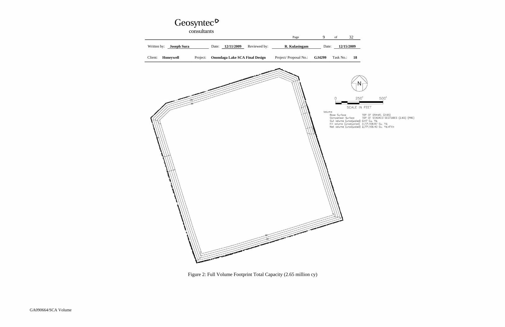
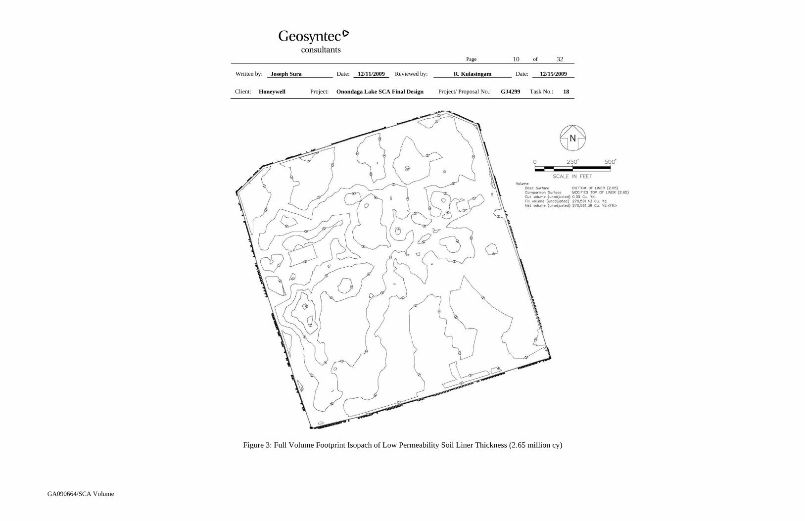
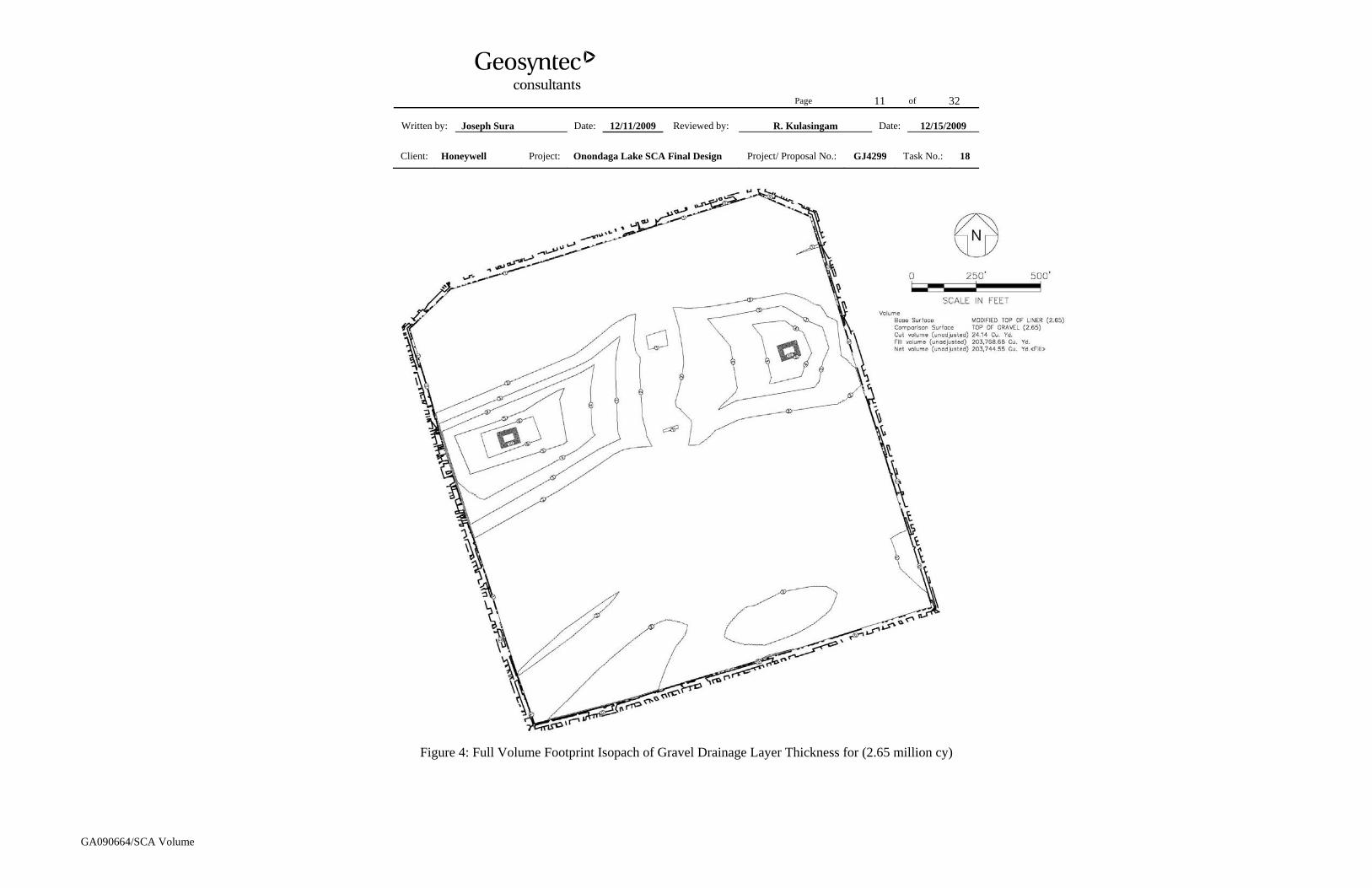
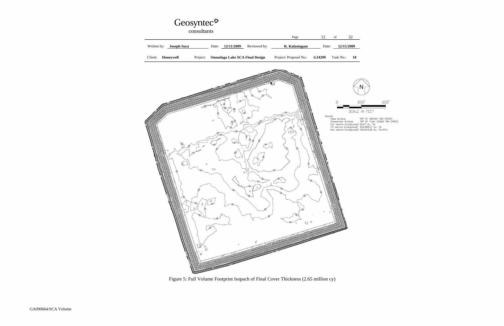
The calculated total dredge material capacity for the full volume footprint is calculated as the difference between the grades shown in Figures A4 and A3 and is shown in Figure 2. Isopachs of the low permeability soil liner (difference between Figures A2 and A1) and gravel drainage layer (difference between Figures A3 and A2) are shown in Figures 3 and 4, respectively. The calculated SCA final cover soil volume is calculated as the difference between the post year 4 settled geo-tubes and the proposed final cover grading (Figures A5 and A6) and is shown in Figure 5. It is noted that this isopach represents the combined thickness of the leveling
Page 3 of 32
Written by: Joseph Sura Date: 12/11/2009 Reviewed by: R. Kulasingam Date: 12/15/2009
Client: Honeywell Project: Onondaga Lake SCA Final Design Project/ Proposal No.: GJ4299 Task No.: 18
GA090664/SCA Volume
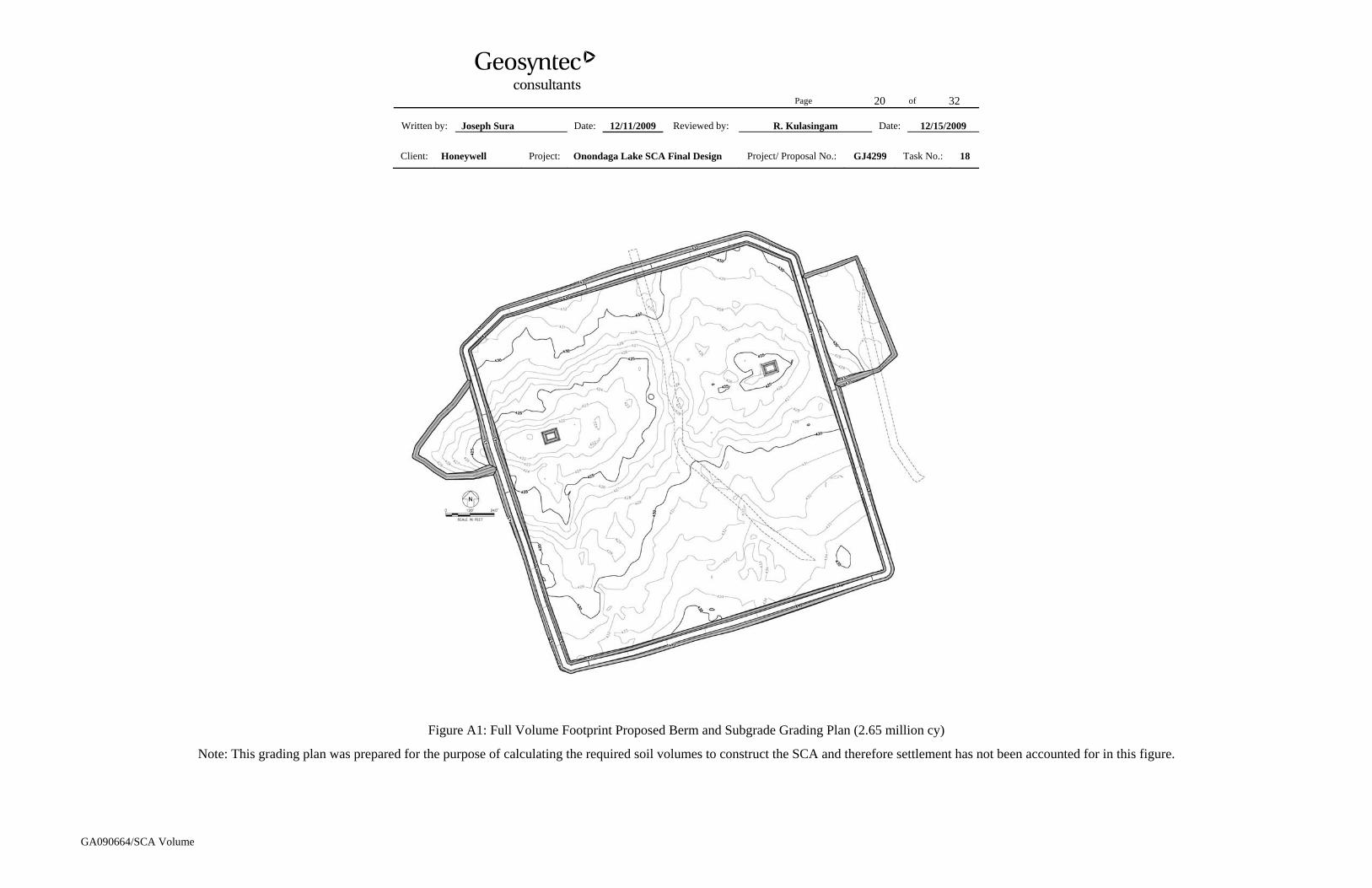
layer, protective soil layer and vegetative layer. The calculated SCA perimeter dike volume for the full volume footprint is calculated as the difference between the existing grades and the proposed berm grading plan shown in Figure A1 and is shown in Figure 6.
The proposed grading plans for the berm and subgrade, low permeability soil liner, gravel drainage layer, and top of geo-tubes for the reduced volume footprint are provided in Attachment B, Figures B1 through B4. It is noted that Figures B1 through B4 have been prepared for purposes of calculating required material volumes and the SCA storage capacity; therefore, settlement has not been accounted for in these figures. The proposed final cover grading has been designed using the top of geo-tube grading after four years of settlement to promote surface water drainage post-closure. Figures B5 and B6 show the calculated top of geo-tube grading after four years of settlement and the proposed final cover grading plan, respectively.
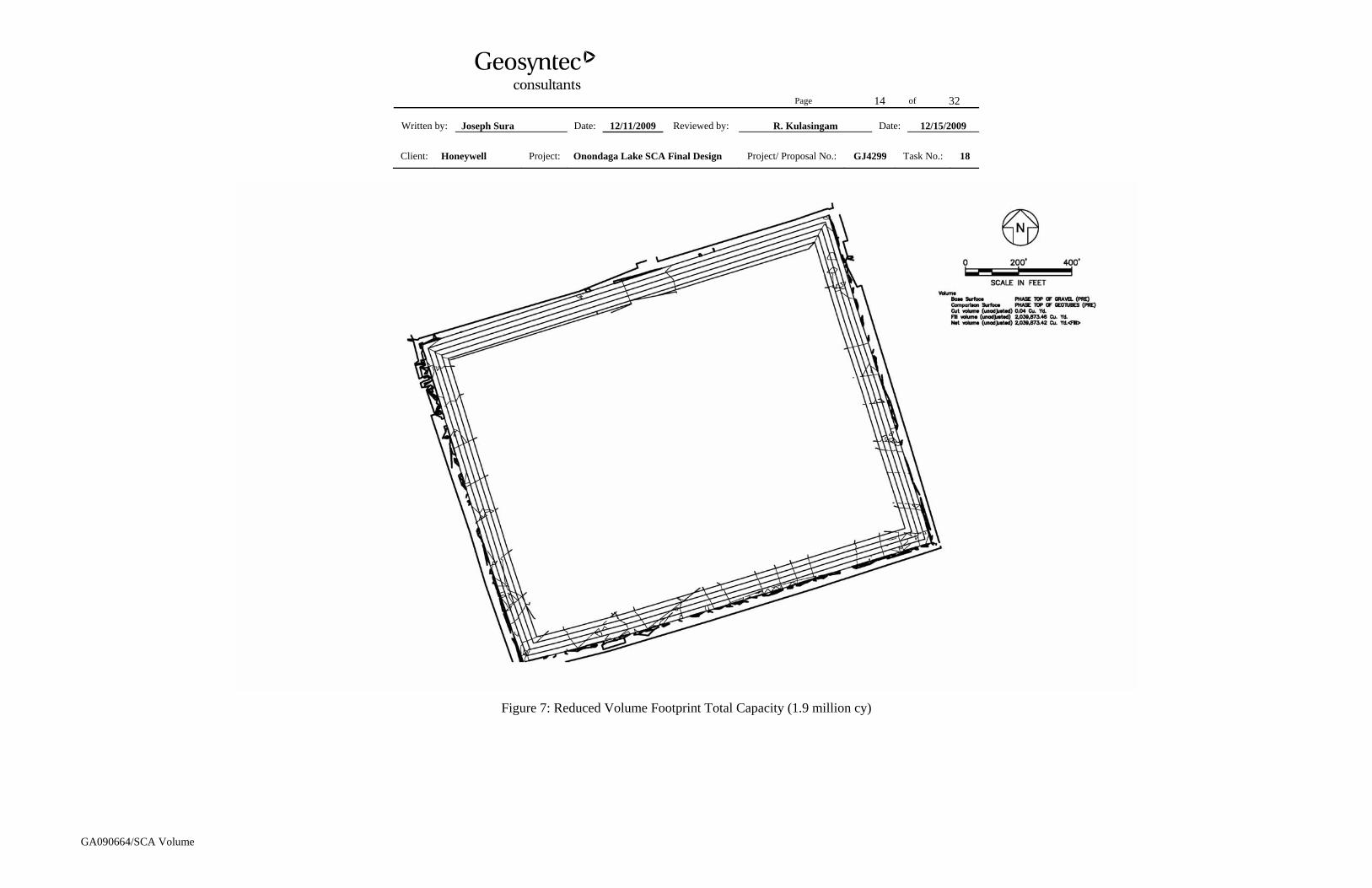
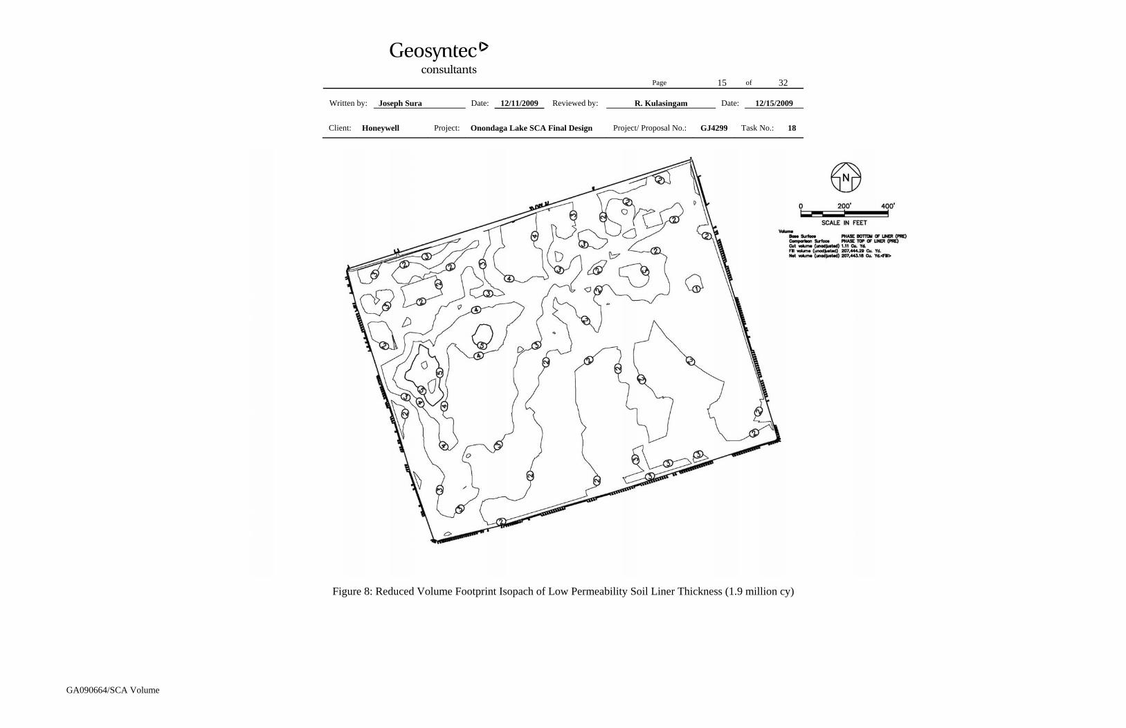
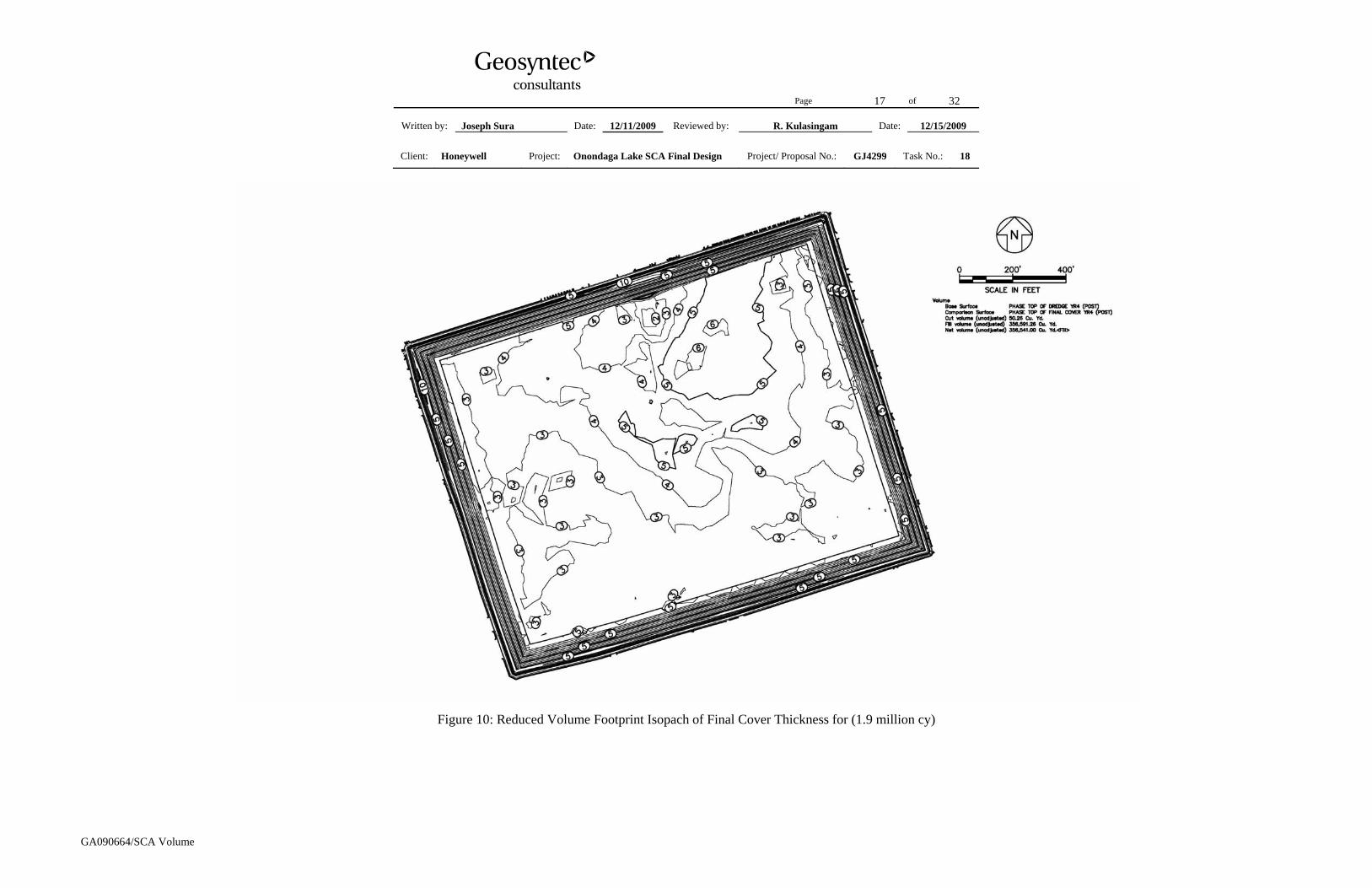
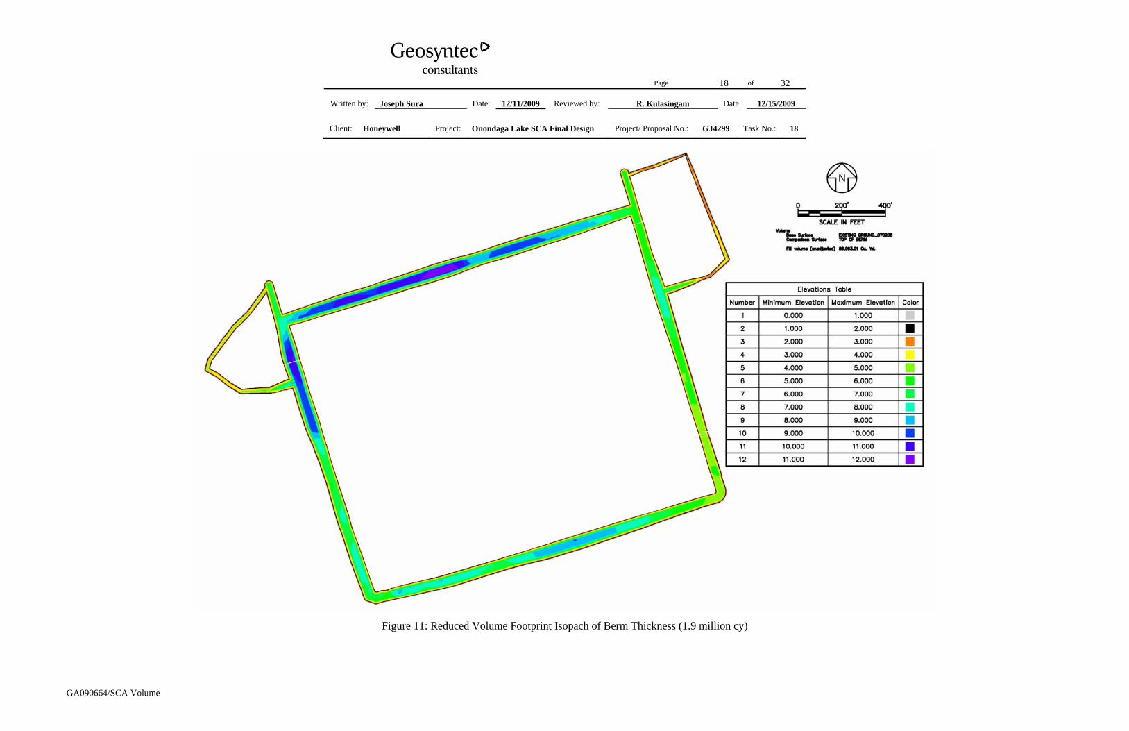
The calculated total dredge material capacity for the reduced volume footprint is calculated as the difference between the grades shown in Figures B4 and B3 and is shown in Figure 7. Isopachs of the low permeability soil liner (difference between Figures B2 and B1) and gravel drainage layer (difference between Figures B3 and B2) are shown in Figures 8 and 9, respectively. The calculated SCA final cover soil volume is calculated as the difference between the post year 4 settled geo-tubes and the proposed final cover grading (Figures B5 and B6) and is shown in Figure 10. It is noted that this isopach represents the combined thickness of the leveling layer, protective soil layer and vegetative layer. The calculated SCA perimeter dike volume for the reduced volume footprint is calculated as the difference between the existing grades and the proposed berm grading plan (Figure B1) and is shown in Figure 11.
RESULTS
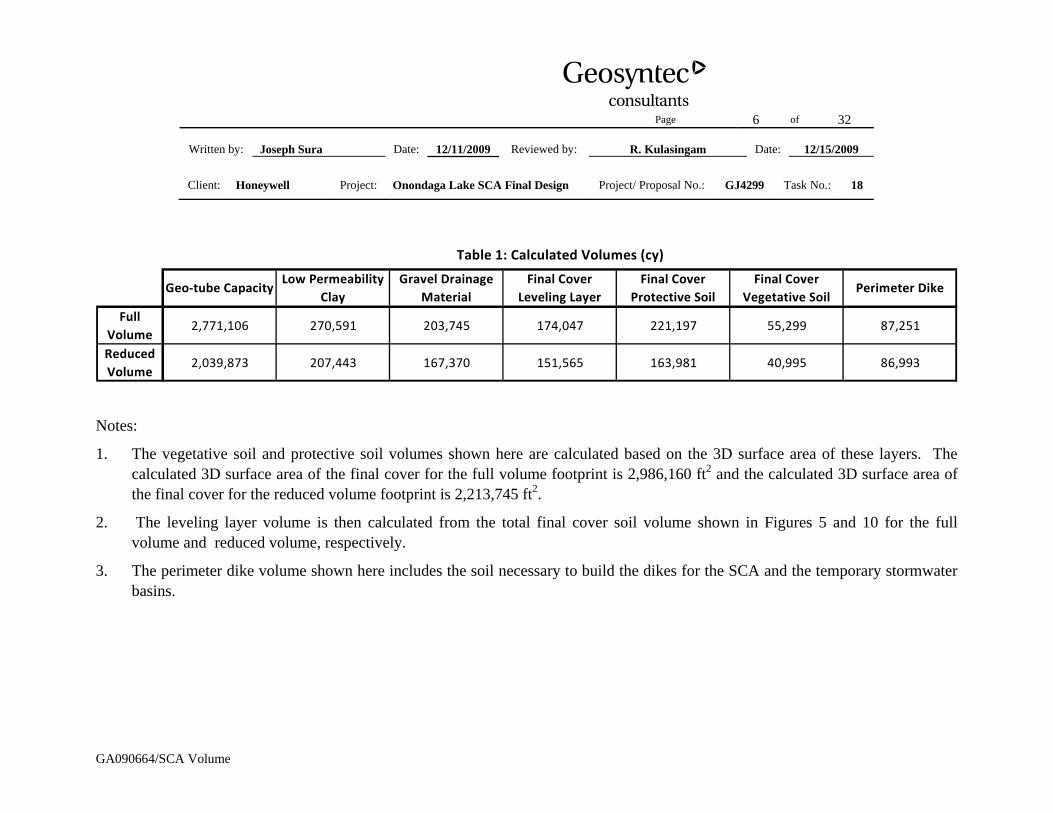
The calculated SCA capacity for dredge material and volumes of low-permeability soil, gravel drainage material, SCA perimeter dike material, and SCA final cover soils for the full volume and reduced volume footprints are shown in Table 1. The results indicate that the proposed SCA full volume and reduced volume footprints meet their respective target capacities. For the full volume footprint, the SCA footprint was estimated to be approximately 75 acres to the outside of the SCA perimeter dike (not including the stormwater basins) and approximately 65 acres to the inside of the SCA perimeter dike (not including the stormwater basins). The average thicknesses of low permeability soil and gravel drainage material were calculated to be 2.6 ft and 2.0 ft, respectively. For the reduced volume footprint, the SCA footprint was estimated to be approximately 58 acres to the outside of the SCA perimeter dike (not including
Page 4 of 32
Written by: Joseph Sura Date: 12/11/2009 Reviewed by: R. Kulasingam Date: 12/15/2009
Client: Honeywell Project: Onondaga Lake SCA Final Design Project/ Proposal No.: GJ4299 Task No.: 18
GA090664/SCA Volume
the stormwater basins) and approximately 49 acres to the inside of the SCA perimeter dike (not including the stormwater basins). The average thicknesses of low permeability soil and gravel drainage material were calculated to be 2.6 ft and 2.1 ft, respectively. Review of Figures 3 and 8 (for the full volume and reduced volume, respectively) indicates that the low permeability soil layer has a minimum thickness of 1 ft in the SCA footprint with a thickness of at least 1.8 ft near the sump areas. Also, the review of Figures 4 and 9 (for the full volume and reduced volume, respectively) indicates that the gravel drainage layer has a minimum thickness of 1 ft in the SCA footprint with a thickness of at least 4 ft near the sump areas.
Page 5 of 32
Written by: Joseph Sura Date: 12/11/2009 Reviewed by: R. Kulasingam Date: 12/15/2009
Client: Honeywell Project: Onondaga Lake SCA Final Design Project/ Proposal No.: GJ4299 Task No.: 18
GA090664/SCA Volume
Tables
Page 6 of 32
Written by: Joseph Sura Date: 12/11/2009 Reviewed by: R. Kulasingam Date: 12/15/2009
Client: Honeywell Project: Onondaga Lake SCA Final Design Project/ Proposal No.: GJ4299 Task No.: 18
1. The vegetative soil and protective soil volumes shown here are calculated based on the 3D surface area of these layers. The calculated 3D surface area of the final cover for the full volume footprint is 2,986,160 ft2 and the calculated 3D surface area of the final cover for the reduced volume footprint is 2,213,745 ft2.
2. The leveling layer volume is then calculated from the total final cover soil volume shown in Figures 5 and 10 for the full volume and reduced volume, respectively.
3. The perimeter dike volume shown here includes the soil necessary to build the dikes for the SCA and the temporary stormwater basins.
Page 7 of 32
Written by: Joseph Sura Date: 12/11/2009 Reviewed by: R. Kulasingam Date: 12/15/2009
Client: Honeywell Project: Onondaga Lake SCA Final Design Project/ Proposal No.: GJ4299 Task No.: 18
GA090664/SCA Volume
Figures
Page 8 of 32
Written by: Joseph Sura Date: 12/11/2009 Reviewed by: R. Kulasingam Date: 12/15/2009
Client: Honeywell Project: Onondaga Lake SCA Final Design Project/ Proposal No.: GJ4299 Task No.: 18
GA090664/SCA Volume
Figure 1: Proposed SCA Full Volume and Reduced Volume Footprints
Page 9 of 32
Written by: Joseph Sura Date: 12/11/2009 Reviewed by: R. Kulasingam Date: 12/15/2009
Client: Honeywell Project: Onondaga Lake SCA Final Design Project/ Proposal No.: GJ4299 Task No.: 18
GA090664/SCA Volume
Figure 2: Full Volume Footprint Total Capacity (2.65 million cy)
30 18
30 18
Page 10 of 32
Written by: Joseph Sura Date: 12/11/2009 Reviewed by: R. Kulasingam Date: 12/15/2009
Client: Honeywell Project: Onondaga Lake SCA Final Design Project/ Proposal No.: GJ4299 Task No.: 18
GA090664/SCA Volume
Figure 3: Full Volume Footprint Isopach of Low Permeability Soil Liner Thickness (2.65 million cy)
Page 11 of 32
Written by: Joseph Sura Date: 12/11/2009 Reviewed by: R. Kulasingam Date: 12/15/2009
Client: Honeywell Project: Onondaga Lake SCA Final Design Project/ Proposal No.: GJ4299 Task No.: 18
GA090664/SCA Volume
Figure 4: Full Volume Footprint Isopach of Gravel Drainage Layer Thickness for (2.65 million cy)
Page 12 of 32
Written by: Joseph Sura Date: 12/11/2009 Reviewed by: R. Kulasingam Date: 12/15/2009
Client: Honeywell Project: Onondaga Lake SCA Final Design Project/ Proposal No.: GJ4299 Task No.: 18
GA090664/SCA Volume
Figure 5: Full Volume Footprint Isopach of Final Cover Thickness (2.65 million cy)
Page 13 of 32
Written by: Joseph Sura Date: 12/11/2009 Reviewed by: R. Kulasingam Date: 12/15/2009
Client: Honeywell Project: Onondaga Lake SCA Final Design Project/ Proposal No.: GJ4299 Task No.: 18
GA090664/SCA Volume
Figure 6: Full Volume Footprint Isopach of Berm Thickness (2.65 million cy)
Page 14 of 32
Written by: Joseph Sura Date: 12/11/2009 Reviewed by: R. Kulasingam Date: 12/15/2009
Client: Honeywell Project: Onondaga Lake SCA Final Design Project/ Proposal No.: GJ4299 Task No.: 18
GA090664/SCA Volume
Figure 7: Reduced Volume Footprint Total Capacity (1.9 million cy)
Page 15 of 32
Written by: Joseph Sura Date: 12/11/2009 Reviewed by: R. Kulasingam Date: 12/15/2009
Client: Honeywell Project: Onondaga Lake SCA Final Design Project/ Proposal No.: GJ4299 Task No.: 18
GA090664/SCA Volume
Figure 8: Reduced Volume Footprint Isopach of Low Permeability Soil Liner Thickness (1.9 million cy)
Page 16 of 32
Written by: Joseph Sura Date: 12/11/2009 Reviewed by: R. Kulasingam Date: 12/15/2009
Client: Honeywell Project: Onondaga Lake SCA Final Design Project/ Proposal No.: GJ4299 Task No.: 18
GA090664/SCA Volume
Figure 9: Reduced Volume Footprint Isopach of Gravel Drainage Layer Thickness for (1.9 million cy)
Page 17 of 32
Written by: Joseph Sura Date: 12/11/2009 Reviewed by: R. Kulasingam Date: 12/15/2009
Client: Honeywell Project: Onondaga Lake SCA Final Design Project/ Proposal No.: GJ4299 Task No.: 18
GA090664/SCA Volume
Figure 10: Reduced Volume Footprint Isopach of Final Cover Thickness for (1.9 million cy)
Page 18 of 32
Written by: Joseph Sura Date: 12/11/2009 Reviewed by: R. Kulasingam Date: 12/15/2009
Client: Honeywell Project: Onondaga Lake SCA Final Design Project/ Proposal No.: GJ4299 Task No.: 18
GA090664/SCA Volume
Figure 11: Reduced Volume Footprint Isopach of Berm Thickness (1.9 million cy)
Page 19 of 32
Written by: Joseph Sura Date: 12/11/2009 Reviewed by: R. Kulasingam Date: 12/15/2009
Client: Honeywell Project: Onondaga Lake SCA Final Design Project/ Proposal No.: GJ4299 Task No.: 18
GA090664/SCA Volume
Attachment A: Full Volume Footprint Grading Plans
Page 20 of 32
Written by: Joseph Sura Date: 12/11/2009 Reviewed by: R. Kulasingam Date: 12/15/2009
Client: Honeywell Project: Onondaga Lake SCA Final Design Project/ Proposal No.: GJ4299 Task No.: 18
GA090664/SCA Volume
Figure A1: Full Volume Footprint Proposed Berm and Subgrade Grading Plan (2.65 million cy)
Note: This grading plan was prepared for the purpose of calculating the required soil volumes to construct the SCA and therefore settlement has not been accounted for in this figure.
Page 21 of 32
Written by: Joseph Sura Date: 12/11/2009 Reviewed by: R. Kulasingam Date: 12/15/2009
Client: Honeywell Project: Onondaga Lake SCA Final Design Project/ Proposal No.: GJ4299 Task No.: 18
GA090664/SCA Volume
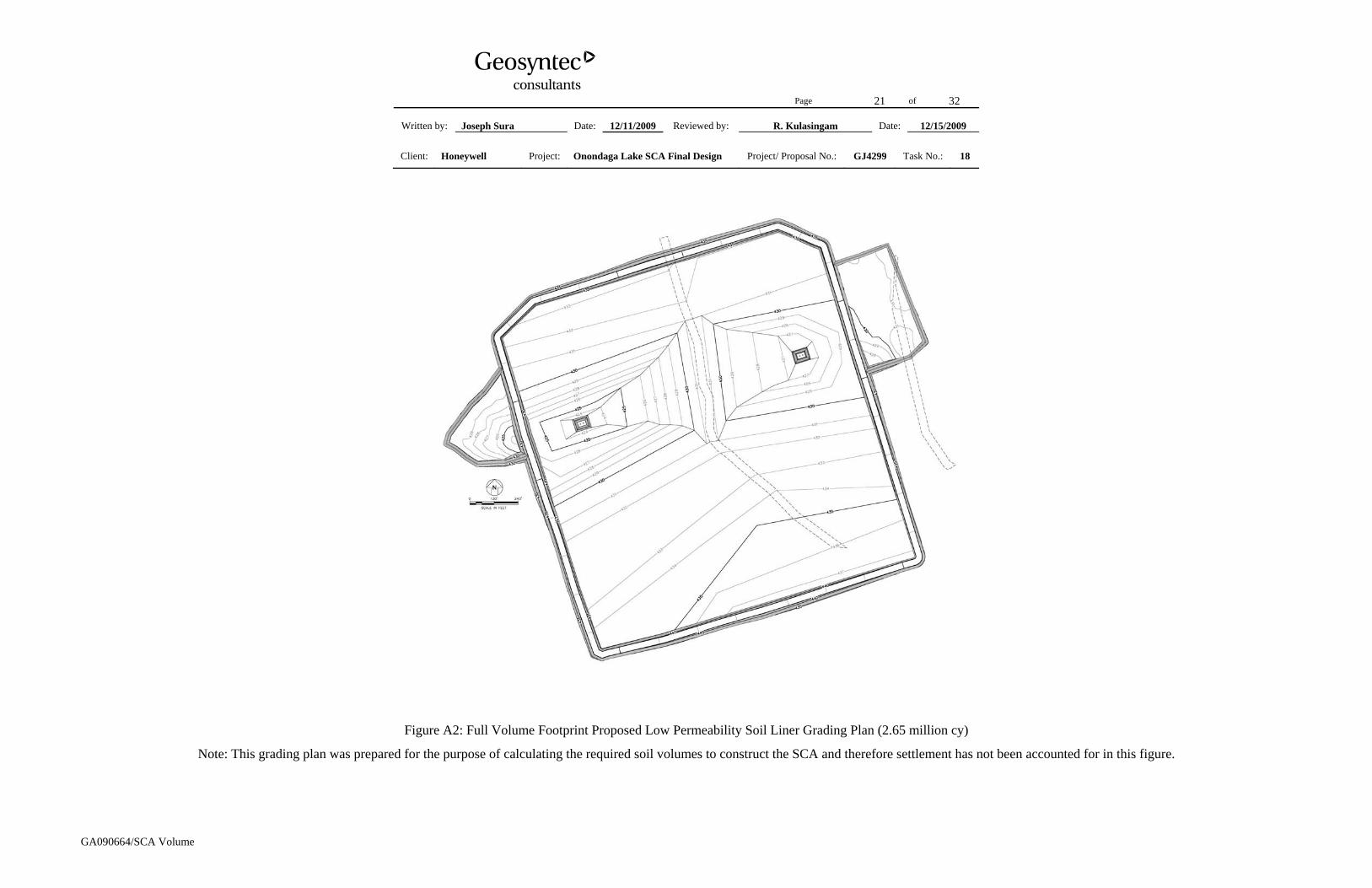
Figure A2: Full Volume Footprint Proposed Low Permeability Soil Liner Grading Plan (2.65 million cy)
Note: This grading plan was prepared for the purpose of calculating the required soil volumes to construct the SCA and therefore settlement has not been accounted for in this figure.
Page 22 of 32
Written by: Joseph Sura Date: 12/11/2009 Reviewed by: R. Kulasingam Date: 12/15/2009
Client: Honeywell Project: Onondaga Lake SCA Final Design Project/ Proposal No.: GJ4299 Task No.: 18
GA090664/SCA Volume
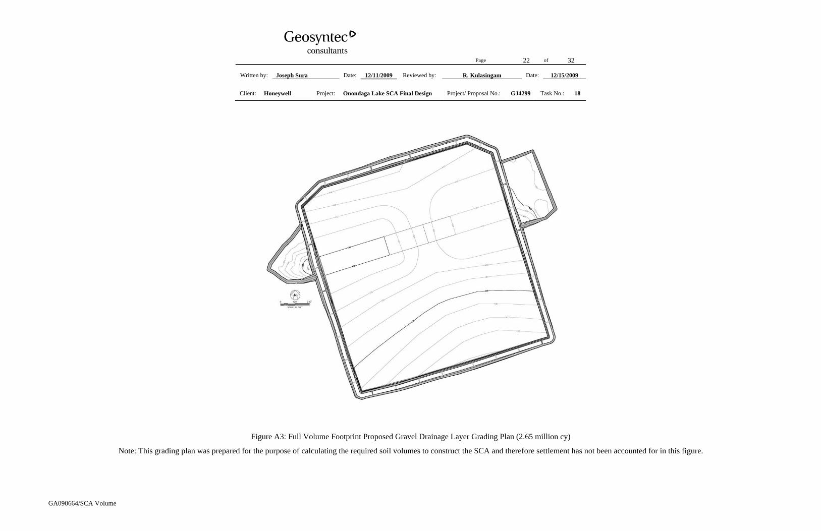
Figure A3: Full Volume Footprint Proposed Gravel Drainage Layer Grading Plan (2.65 million cy)
Note: This grading plan was prepared for the purpose of calculating the required soil volumes to construct the SCA and therefore settlement has not been accounted for in this figure.
Page 23 of 32
Written by: Joseph Sura Date: 12/11/2009 Reviewed by: R. Kulasingam Date: 12/15/2009
Client: Honeywell Project: Onondaga Lake SCA Final Design Project/ Proposal No.: GJ4299 Task No.: 18
GA090664/SCA Volume
Figure A4: Full Volume Footprint Proposed Top of Geo-tube Grading Plan (2.65 million cy)
Note: This grading plan was prepared for the purpose of calculating the storage capacity of the SCA and therefore settlement has not been accounted for in this figure.
Page 24 of 32
Written by: Joseph Sura Date: 12/11/2009 Reviewed by: R. Kulasingam Date: 12/15/2009
Client: Honeywell Project: Onondaga Lake SCA Final Design Project/ Proposal No.: GJ4299 Task No.: 18
GA090664/SCA Volume
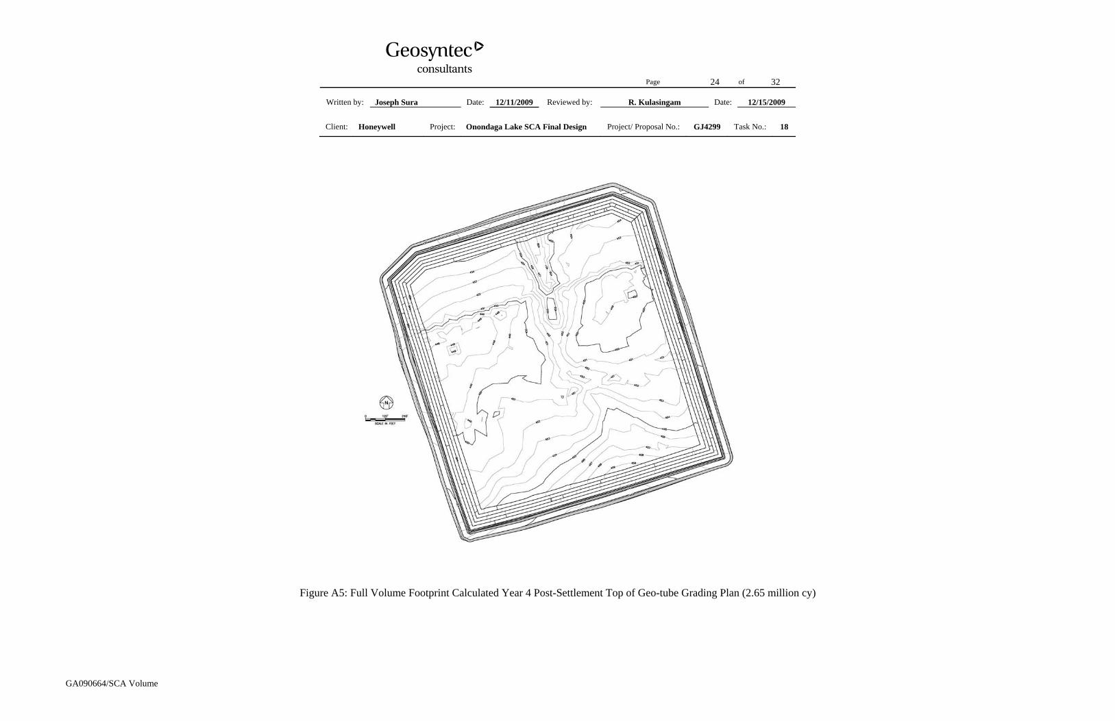
Figure A5: Full Volume Footprint Calculated Year 4 Post-Settlement Top of Geo-tube Grading Plan (2.65 million cy)
Page 25 of 32
Written by: Joseph Sura Date: 12/11/2009 Reviewed by: R. Kulasingam Date: 12/15/2009
Client: Honeywell Project: Onondaga Lake SCA Final Design Project/ Proposal No.: GJ4299 Task No.: 18
GA090664/SCA Volume
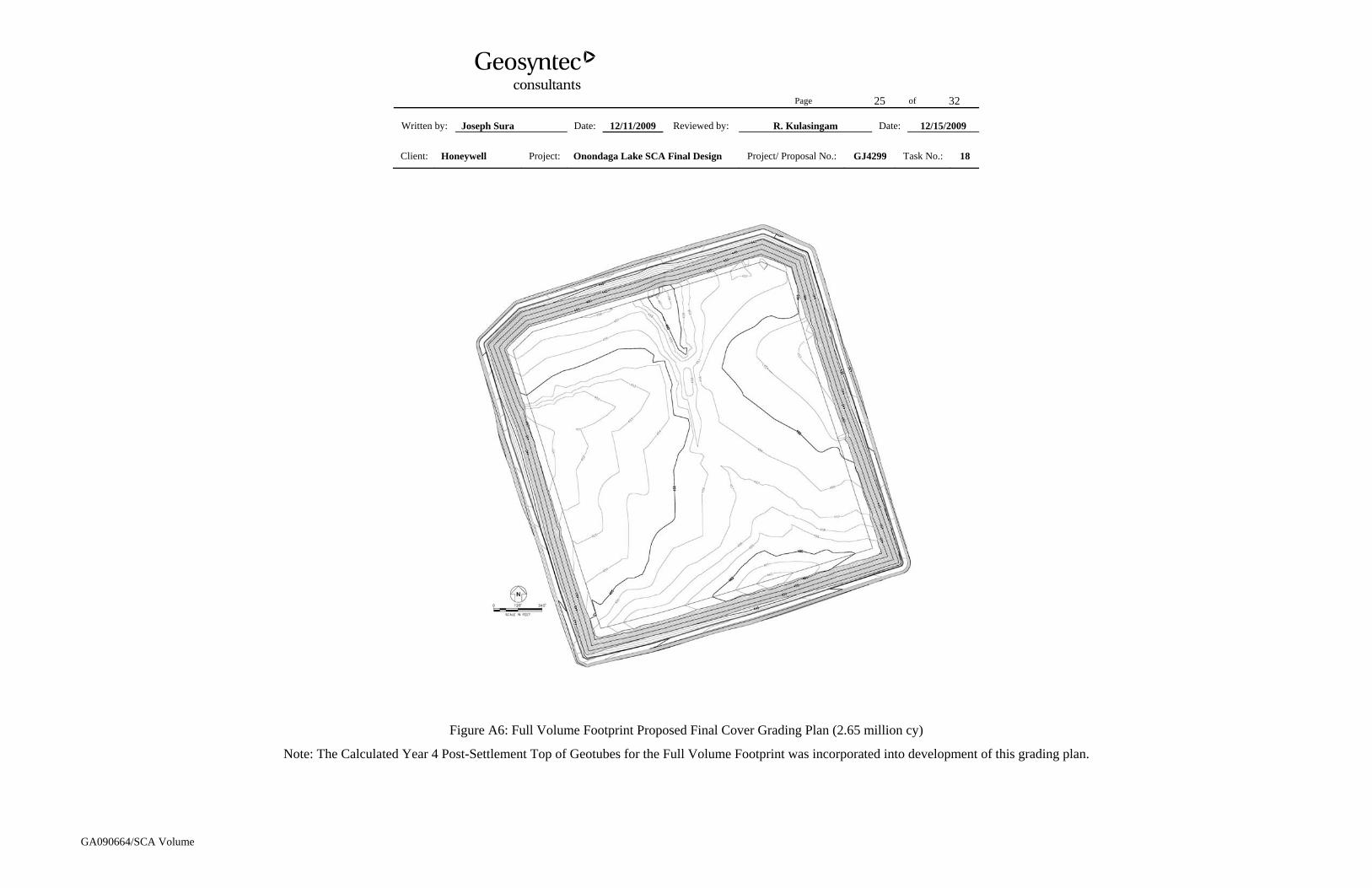
Figure A6: Full Volume Footprint Proposed Final Cover Grading Plan (2.65 million cy)
Note: The Calculated Year 4 Post-Settlement Top of Geotubes for the Full Volume Footprint was incorporated into development of this grading plan.
Page 26 of 32
Written by: Joseph Sura Date: 12/11/2009 Reviewed by: R. Kulasingam Date: 12/15/2009
Client: Honeywell Project: Onondaga Lake SCA Final Design Project/ Proposal No.: GJ4299 Task No.: 18
Written by: Joseph Sura Date: 12/11/2009 Reviewed by: R. Kulasingam Date: 12/15/2009
Client: Honeywell Project: Onondaga Lake SCA Final Design Project/ Proposal No.: GJ4299 Task No.: 18
GA090664/SCA Volume
Figure B1: Reduced Volume Footprint Proposed Berm and Subgrade Grading Plan (1.9 million cy)
Note: This grading plan was prepared for the purpose of calculating the required soil volumes to construct the SCA and therefore settlement has not been accounted for in this figure.
Page 28 of 32
Written by: Joseph Sura Date: 12/11/2009 Reviewed by: R. Kulasingam Date: 12/15/2009
Client: Honeywell Project: Onondaga Lake SCA Final Design Project/ Proposal No.: GJ4299 Task No.: 18
GA090664/SCA Volume
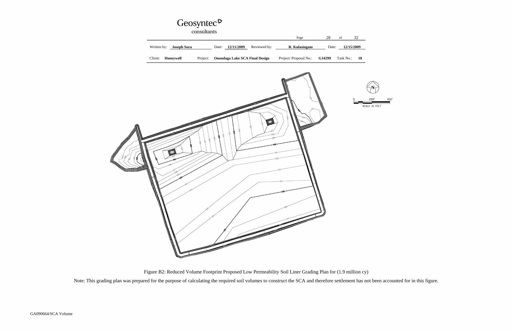
Figure B2: Reduced Volume Footprint Proposed Low Permeability Soil Liner Grading Plan for (1.9 million cy)
Note: This grading plan was prepared for the purpose of calculating the required soil volumes to construct the SCA and therefore settlement has not been accounted for in this figure.
Page 29 of 32
Written by: Joseph Sura Date: 12/11/2009 Reviewed by: R. Kulasingam Date: 12/15/2009
Client: Honeywell Project: Onondaga Lake SCA Final Design Project/ Proposal No.: GJ4299 Task No.: 18
GA090664/SCA Volume
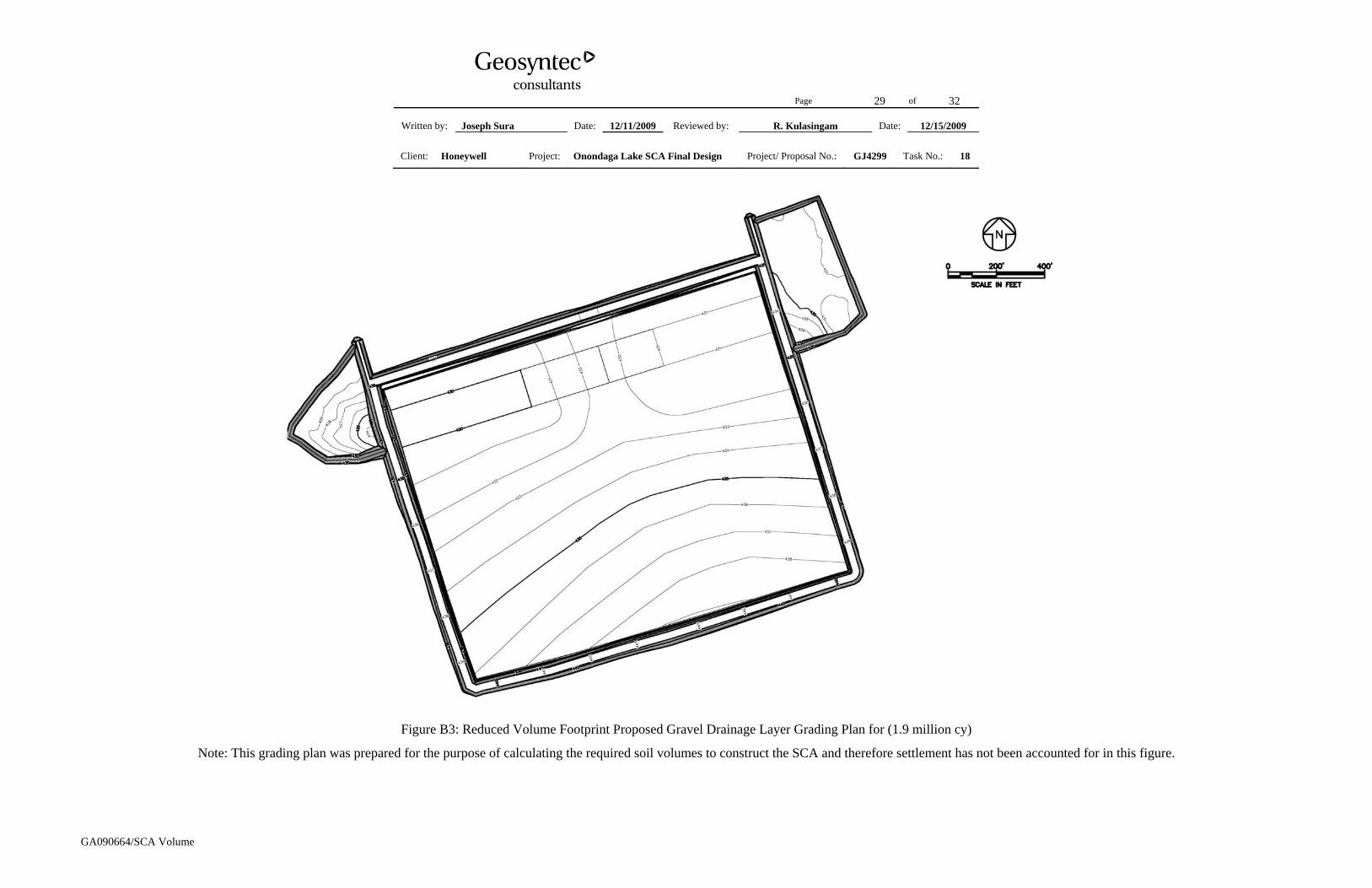
Figure B3: Reduced Volume Footprint Proposed Gravel Drainage Layer Grading Plan for (1.9 million cy)
Note: This grading plan was prepared for the purpose of calculating the required soil volumes to construct the SCA and therefore settlement has not been accounted for in this figure.
Page 30 of 32
Written by: Joseph Sura Date: 12/11/2009 Reviewed by: R. Kulasingam Date: 12/15/2009
Client: Honeywell Project: Onondaga Lake SCA Final Design Project/ Proposal No.: GJ4299 Task No.: 18
GA090664/SCA Volume
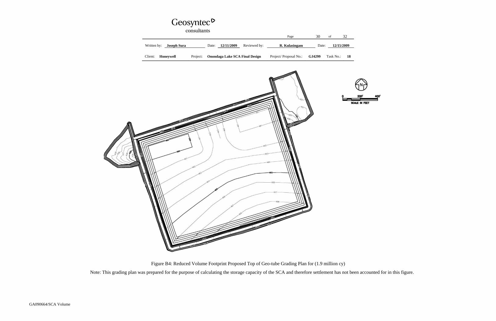
Figure B4: Reduced Volume Footprint Proposed Top of Geo-tube Grading Plan for (1.9 million cy)
Note: This grading plan was prepared for the purpose of calculating the storage capacity of the SCA and therefore settlement has not been accounted for in this figure.
Page 31 of 32
Written by: Joseph Sura Date: 12/11/2009 Reviewed by: R. Kulasingam Date: 12/15/2009
Client: Honeywell Project: Onondaga Lake SCA Final Design Project/ Proposal No.: GJ4299 Task No.: 18
GA090664/SCA Volume
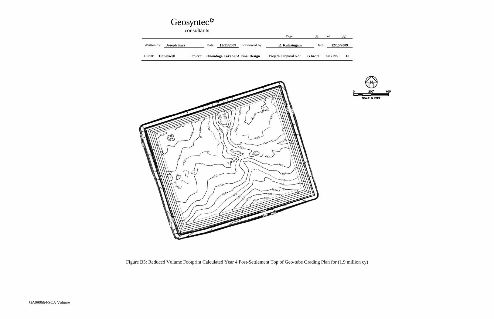
Figure B5: Reduced Volume Footprint Calculated Year 4 Post-Settlement Top of Geo-tube Grading Plan for (1.9 million cy)
Page 32 of 32
Written by: Joseph Sura Date: 12/11/2009 Reviewed by: R. Kulasingam Date: 12/15/2009
Client: Honeywell Project: Onondaga Lake SCA Final Design Project/ Proposal No.: GJ4299 Task No.: 18
GA090664/SCA Volume
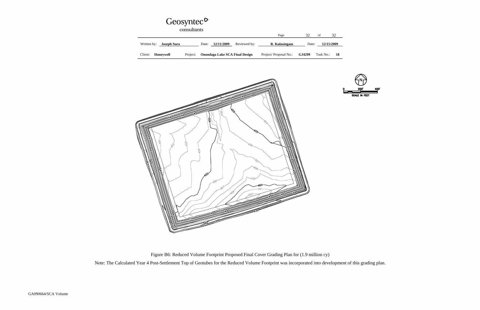
Figure B6: Reduced Volume Footprint Proposed Final Cover Grading Plan for (1.9 million cy)
Note: The Calculated Year 4 Post-Settlement Top of Geotubes for the Reduced Volume Footprint was incorporated into development of this grading plan.