Appendix G: The construction of the HSM 814. Weights. Sources Drawings in the Utrecht archive: - General plan, longitudinal sections vertically and horizontally - Various line drawings steam / air etc. - Photos Netherlands Railway Museum - Steam Locomotive NS 2104 (HSM 504) - Drawings of NS 1900, NS 2100 and NS 5800 Books - Harterink and Mook, shown here for details - Labrijn - Franklin brochure Construction details General: it makes no sense to reproduce in full many historical details. The locomotive should be fabricated as economical as possible. Modern techniques, welding and the like and modern equipment should be used. Frame The frame is to be reconstructed from the General Arrangement Plan. The thickness of the frame plates is 28 mm. Along - and cross connections are conform the General Arrangement: buffer beams fore and aft, cylinder block and truck connections fore, inside motionplate, stiffening in front of firebox, the same behind and the mounting of the rear bogie. The bufferbeams and the traction chest could be according to the NS 2100 version. Because of the greater possibility of cracking in locomotives with two inside cylinders adjustable hornblocks with adjustable wedges are chosen, however, r selfadjustment. according to Franklin-version with spring-loaded wedges fo The classical implementation of a hornblocks did not have any additional inforcement in the upper corners, often it had a support for the axlebox face itself. hat support was aimed in the direction of possible cracks. The upper corners of the nclose the re T hornblocks are to be as stiff as possible and the hornstay should therefore e bottom part of the hornblock as well as the frame.
Transcript
Appendix G: The construction of the HSM 814. Weights. Sources Drawings in the Utrecht archive:
- General plan, longitudinal sections vertically and horizontally - Various line drawings steam / air etc. - Photos
Netherlands Railway Museum - Steam Locomotive NS 2104 (HSM 504) - Drawings of NS 1900, NS 2100 and NS 5800
Books - Harterink and Mook, shown here for details - Labrijn - Franklin brochure
Construction details General: it makes no sense to reproduce in full many historical details. The locomotive should be fabricated as economical as possible. Modern techniques, welding and the like and modern equipment should be used. Frame The frame is to be reconstructed from the General Arrangement Plan. The thickness of the frame plates is 28 mm. Along - and cross connections are conform the General Arrangement: buffer beams fore and aft, cylinder block and truck connections fore, inside motionplate, stiffening in front of firebox, the same behind and the mounting of the rear bogie. The bufferbeams and the traction chest could be according to the NS 2100 version. Because of the greater possibility of cracking in locomotives with two inside cylinders adjustable hornblocks with adjustable wedges are chosen, however,
r selfadjustment.
according to Franklin-version with spring-loaded wedges fo
The classical implementation of a hornblocks did not have any additional
inforcement in the upper corners, often it had a support for the axlebox face itself. hat support was aimed in the direction of possible cracks. The upper corners of the
nclose the
reThornblocks are to be as stiff as possible and the hornstay should therefore ebottom part of the hornblock as well as the frame.
Cylinder Block. This could be reproduced in a welded construction. The changes for short channels in
e cylinder blocks as applied in the NS 3700/6100 should be used in the steam chest.
rawing
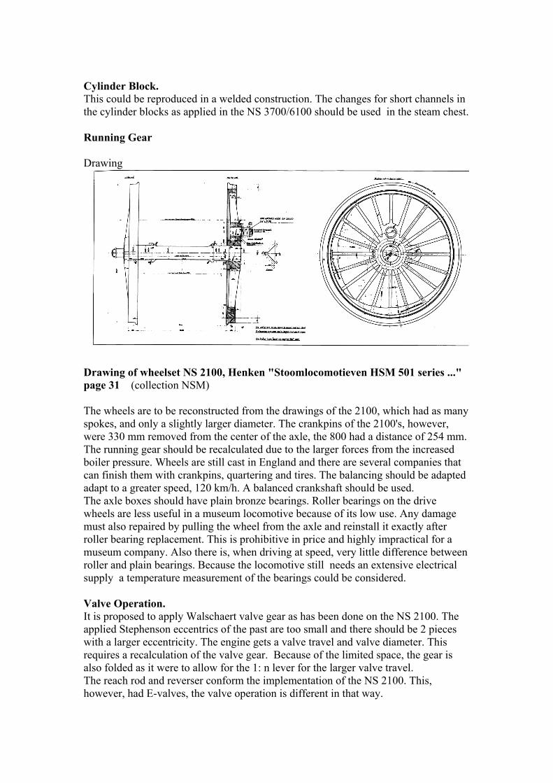
th Running Gear D
Drawing of wheelset NS 2100, Henken "Stoomlocomotieven HSM 501 series ..." page 31 (collection NSM)
ger diameter. The crankpins of the 2100's, however,
ere 330 mm removed from the center of the axle, the 800 had a distance of 254 mm.
at
after a
n l
2100. The plied Stephenson eccentrics of the past are too small and there should be 2 pieces
icity. The engine gets a valve travel and valve diameter. This
The wheels are to be reconstructed from the drawings of the 2100, which had as manyspokes, and only a slightly larwThe running gear should be recalculated due to the larger forces from the increased boiler pressure. Wheels are still cast in England and there are several companies thcan finish them with crankpins, quartering and tires. The balancing should be adapted adapt to a greater speed, 120 km/h. A balanced crankshaft should be used. The axle boxes should have plain bronze bearings. Roller bearings on the drive wheels are less useful in a museum locomotive because of its low use. Any damage must also repaired by pulling the wheel from the axle and reinstall it exactlyroller bearing replacement. This is prohibitive in price and highly impractical formuseum company. Also there is, when driving at speed, very little difference betweeroller and plain bearings. Because the locomotive still needs an extensive electricasupply a temperature measurement of the bearings could be considered. Valve Operation. It is proposed to apply Walschaert valve gear as has been done on the NS apwith a larger eccentrrequires a recalculation of the valve gear. Because of the limited space, the gear is also folded as it were to allow for the 1: n lever for the larger valve travel. The reach rod and reverser conform the implementation of the NS 2100. This, however, had E-valves, the valve operation is different in that way.
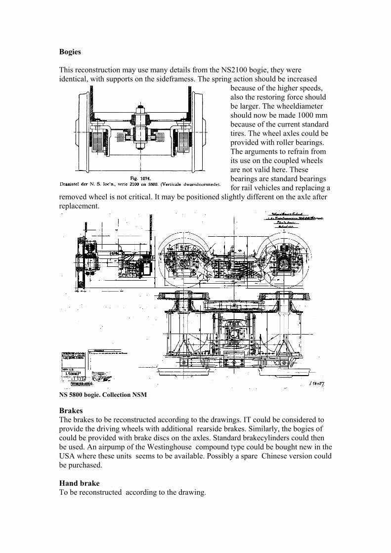
Bogies This reconstruction may use many details from the NS2100 bogie, they were
, with supports on the sideframess. The spring action should be increased because of the higher speeds,
should
be
ing a ig
replacement.
identical
also the restoring force be larger. The wheeldiameter should now be made 1000 mm because of the current standard tires. The wheel axles couldprovided with roller bearings. The arguments to refrain from its use on the coupled wheels are not valid here. These bearings are standard bearings for rail vehicles and replachtly different on the axle afterremoved wheel is not critical. It may be positioned sl
NS 5800 bogie. Collection NSM
rakes d according to the drawings. IT could be considered to
rovide the driving wheels with additional rearside brakes. Similarly, the bogies of provided with brake discs on the axles. Standard brakecylinders could then
e ld
cted according to the drawing.
BThe brakes to be reconstructepcould be be used. An airpump of the Westinghouse compound type could be bought new in thUSA where these units seems to be available. Possibly a spare Chinese version coube purchased. Hand brake To be reconstru
Boiler
Boiler of the NS 1900/5806. Collection NSM
he boiler to be fabricated in a fully welded constuction. The boiler plate had a cient for the current desired 15 bar. The boiler
hell could be increased in order to at least maintain the weight of the boiler. The eater.
be a fferent exhauststand and a 4-row collection box for the superheater elements
Tthickness of 13 mm. This could be suffisamounts of tubes and flues are to changed because of the new area of the superhThe boiler could be positioned higher on the frame than the original engine. Smoke box The smoke box to be adapted to the other boiler location. Internally there will di Components The appendages to be fabricated according to the NS 2100 example.
It should always be possible to close the fire door. The safety valves and steam dome according to the HSM 806-812. Several lubricators to be adapted to the present state of technique (trucks). Grease lubrication where possible, cylinder oil where not. The whistle, lanterns and the like to be reconstructed. Injectors The locomotives were equipped with 2 Gresham & Craven injectors No 9, with a 9 mm nozzle and a yield of 4800 to 7200 liters / hour. In connection with the higher pressure that is applied attention should be given to the yield, the C & G NR 9 would have a lower capacity, obtained from a higher pressure.
The pipes and the location of the injector G & C No. 9,
Footplate /walking boards The foot plate to be redesigned according to the General Arrangement Plan. Depending on the weight distribution on the driving wheels adding extra weight is possible. In any case, if possible, weight should be added for this use. Side tanks The side tanks to be redesigned according to drawing L 58024, if possible to be made 200mm higher. Aft Tank / coal scuttle Ditto, the height does not change. Engine House The engine houde to be reconstructed according to the drawing of the 806-812 (high) version, L 58024/25. The equipment within according to the NS 2104 Remaining Sanding device
The sanding equipment according to the General Arrangement Plan: A spreader for front - and back driving to front and rear drive wheels
The steam locomotive used steam on the initial operation of the sanding unit. This could be changed to air operation as on the latest type of NS railway locomotives, this due to the occurrence of moisture. Electricity Because of the required data logger and the Automatic Train Safety system electricity must be provided such as a truck alternator on the rear axle of the rear bogie (?) A battery of 24 or 48 Volt is a part of this system because of back-up requirements. This could also be recharged in the locomotive shed.
The weight calculation Eckhart, in his book "Das Entwerfen von Dampflokomotiven" provided a number of formulas to estimate the weight of a locomotive. These are based on lengths, axle weight, heating surface and the like and historical data. If they are applied, the following table can be given:
1 Weight calculation according to Eckhardt2 Weight total kilo 587353 Individual parts:4 Frame weight 135525 Wheelpressure6 Brakes 201478 Motionwork 62509 Boiler weight 7792
It should be noted that the total weight as calculated in the second column at the top is not the sum of the other calculations, but is calculated with a separate formula. Since the results are quite similar with the realized values it will be reasonable to regard them as fairly truthful. JJGKoopmans July 2012 Rev. 02