November, 2008 Prepared for: New York State Department of Environmental Conservation 625 Broadway Albany, New York 12233-5252 Prepared by: Empire GEO Services, Inc. PO Box 2199 Ballston Spa, New York 12020 Belleayre Mountain Ski Center UMP-DEIS Appendix I SJB Soil Boring Report
Transcript
November, 2008
Prepared for:
New York State Department of Environmental Conservation 625 Broadway
Albany, New York 12233-5252
Prepared by:
Empire GEO Services, Inc. PO Box 2199
Ballston Spa, New York 12020
Belleayre Mountain Ski Center UMP-DEIS
Appendix I
SJB Soil Boring Report
EMPIREG_OS E R V ICE S, INC.
November 14, 2008
Attn: Randall J. Passmann, P.E.
New York State Department of Environmental ConservationBureau ofDesign and Construction625 Broadway - 3rd FloorAlbany, New York 12233-5252tel. (518)402-9053 / fax (518)402-9084o CORPORATE/
BUFFALO OFFICE5167 South Park Avenue
Hamburg. NY 14075Phone: (716) 649-8110
Fax: (716) 649-8051
Re: Soil Boring & Sampling ServicesBelleayre UMPTown of Shandaken, New YorkSJB Project No: AD-08-051
'tizl'. ALBANY OFFICEr PO Box 2199
Ballston Spa. NY 12020
5 Knabner RoadMechanicville. NY 12118
Phone: (518) 899-7491(518) 899-7496
o CORTLAND OFFICE60 Miller street
Cortland. NY 13045Phone: (607) 758-7182
Fax: (607) 758-7188
o ROCHESTER OFFICE535 Summit Point Drive
Henrietta, NY 14467Phone: (585) 359-2730
Fox: (585) 359-9668
Dear Mr. Passmann:
Empire Geo-Services, Inc. is pleased to present this soils investigation reportsummarizing our findings from field work and laboratory analyses performed insupport ofthe referenced project. The work was completed as outlined in the requestfor proposal and scope of work prepared by the New York State Department ofEnviromnental Conservation (NYSDEC), and authorized by NYSDEC purchaseorder no. 011165.
PROJECT DESCRIPTION
As we understand it, a water storage pond is to be constructed at a site along Ulsterand Delaware Turnpike for use by the Belleayre Mountain ski area. Plans call for animpoundment facility about 1400 feet long and 200 feet or more wide, createdthrough cuts and embankment fills ofnative soils. The proposed top ofembankmentelevation is 1929.0 feet, and the pond invert elevation is between 1905.0 and 1910.0feet. Planned embanlanent side slopes are between 1V:2.5H and 1V :3H. Water willbe sourced from an adjacent stream, whereby a portion of its flow will be divertedinto the pond for storage, and via a transmission line from an existing nearby pond(Cathedral Glen). Plans also include pond outlet works and pumping facilities totransmit water to upper and lower mountain areas for use as needed.
, ,
METHOD OF INVESTIGATION
Field Testing:
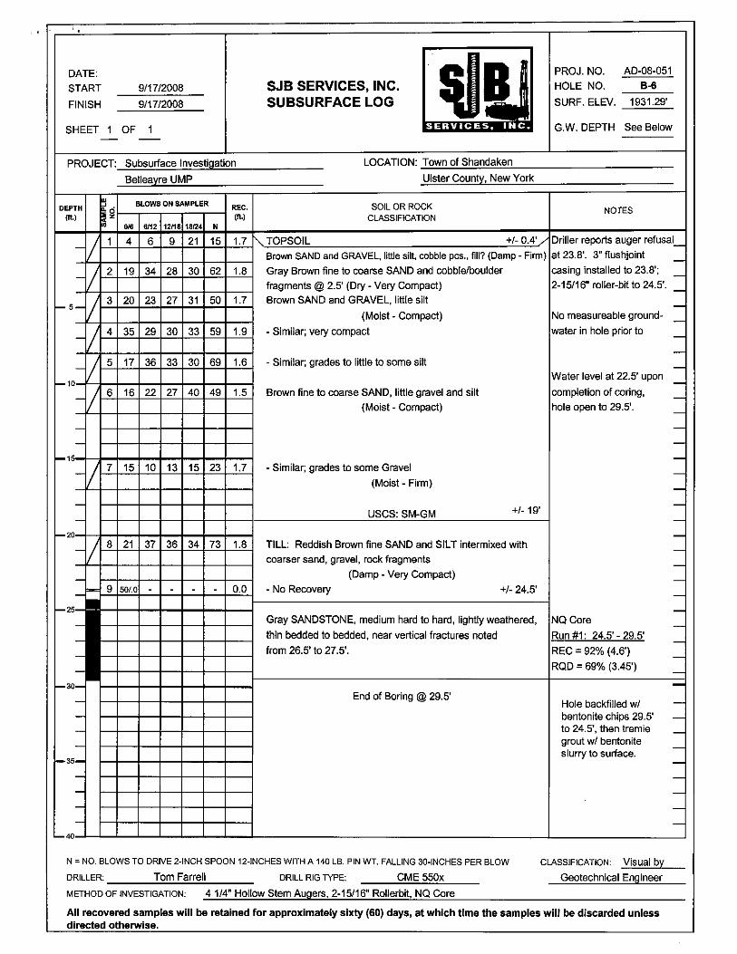
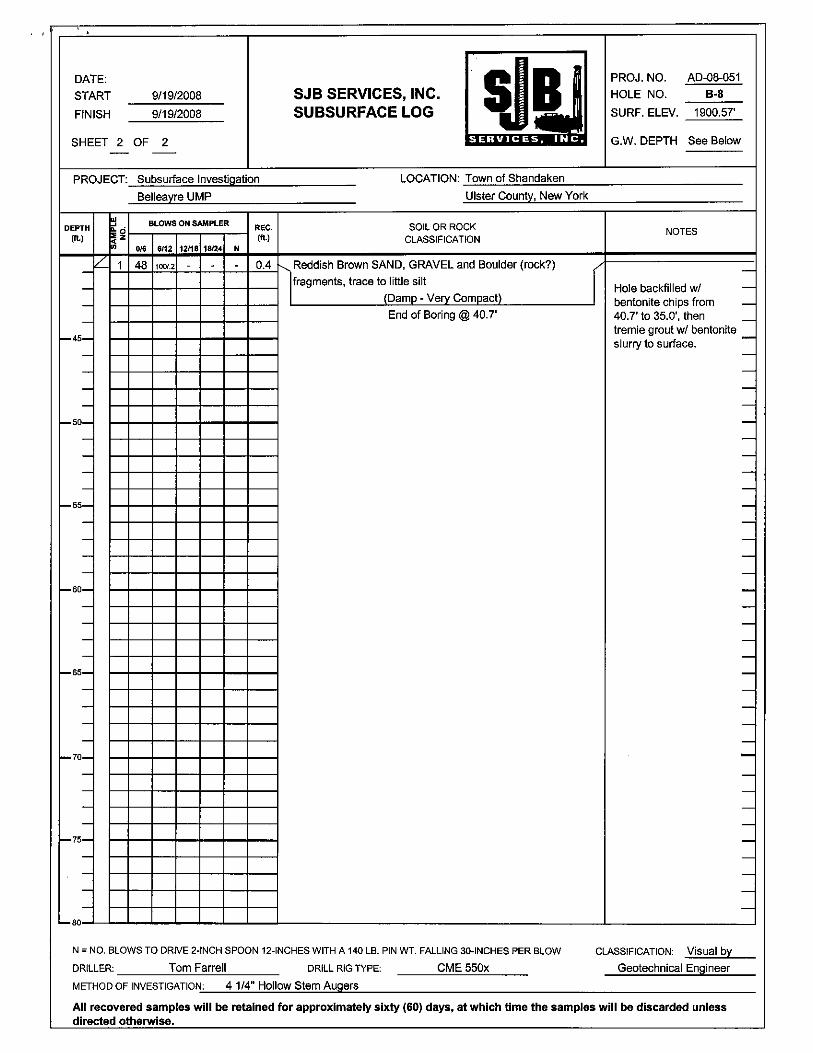
Subsurface conditions at the site were investigated by our affiliated drilling and materials testingfirm, SJB Services, Inc. (SJB). Five test borings (B-4, B-5, B-6, B-7 and B-8) and three test pits(TP-l, TP-2 and TP-3) were performed, as shown on the subsurface investigation plan (Attachment1). ACME 550x all terrain vehicle mounted drill rig equipped with hollow stem augers, flush-jointcasing and rock core tooling was used to complete the test borings. The test pits were excavated witha John Deere 410E rubber-tire backhoe furnished by others.
At locations B-4, B-5 and B-6, soils were sampled on a continuous basis to a depth of 12 feet andat standard five foot intervals thereafter in accordance with ASTM D1586 - Standard Method forPenetration Test and Split-Barrel Sampling ofSoils. At location B-7, soil characterization is basedon a single split spoon sample at the 10 to 12 foot interval and the driller's observations, and at B-8,soils were characterized by the driller based on auger cuttings and other noted aspects ofthe drillingoperation, along with a single split spoon sample taken at the boring termination depth.
Borings B-4 and B-8 were each angered to a target depth of40 feet. At locations B-5, B-6 and B-7,auger refusal was encountered at depths of33.5 feet, 23.8 feet and 25.0 feet respectively. Refusalmaterial encountered in each hole was cored for a length of5 feet in general accordance with ASTMD2113 - Standard Practice for Rock Core Drilling and Sampling ofRock for Site Investigation, usingan NQ size core barreL Representative portions of the recovered split-spoon soil samples, and therecovered rock core in its entirety, were transported Empire's office for visual classification by ageotechnical engineer and/or geologist. :~
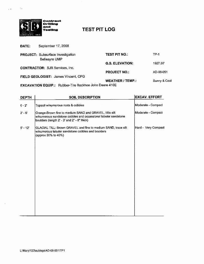
The test pits were excavated to depths of10.5 to 12.5 feet, with each excavation observed and loggedby a geologist. In order to obtain a representative sample of native materials for laboratory testing,two bulk samples were taken from each test pit, at discrete depth intervals of 6 to 7 feet and 9.5 to12 feet. Oversize materials (approximately four inches or larger) were excluded. A single compositesample was prepared from those collected for use in the laboratory testing program described below.
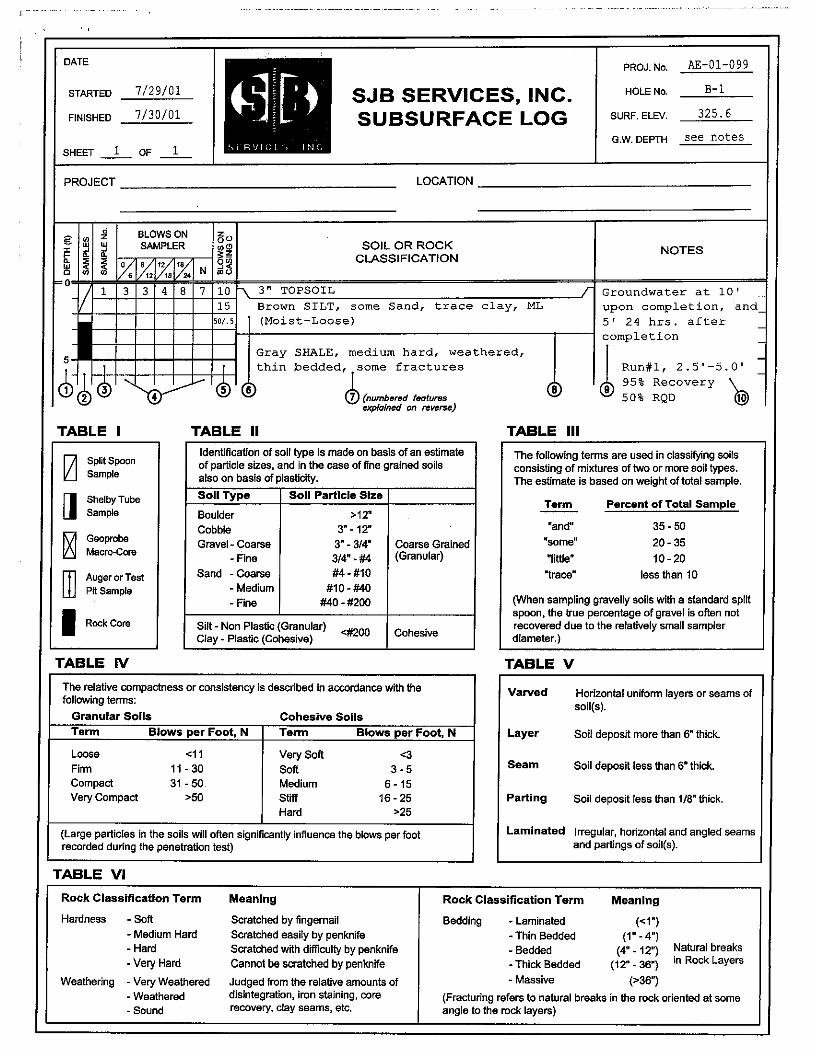
An individual subsurface log was prepared for each ofthe test borings and test pits based upon thevisual classifications and field records. The existing ground surface elevation at each boring and testpit location were furnished by the NYSDEC and are included on the logs. The logs are included inAttachment 2 together with a sheet which explains the terms and symbols used in their preparation.A photograph of the recovered rock core samples is presented in Attachment 3.
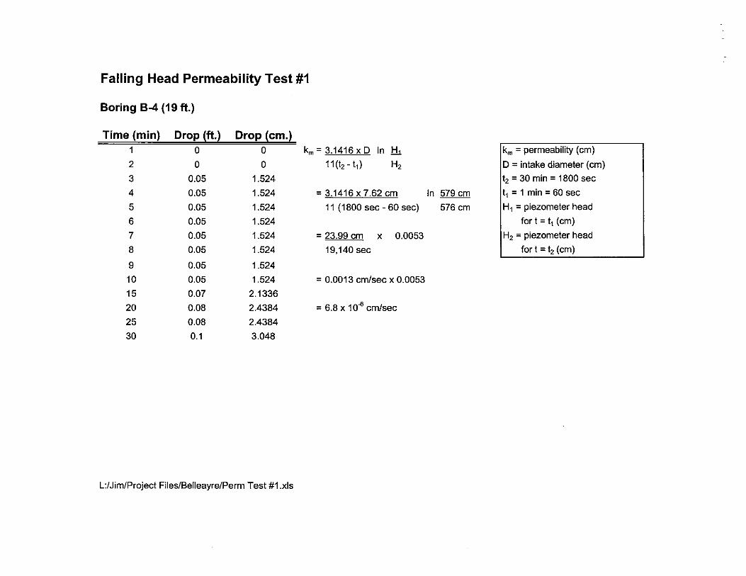
A total of three falling head permeability tests were performed, two at boring B-4 at depths of 19.0and 34.0 feet, and one at B-7 at a depth of 12.5 feet. Prior to each test, three inch diameter flush-jointcasing was installed and seated in the bottom ofthe borehole to facilitate its completion, and uponfilling the casing with water, the drop in water level was recorded at intervals ofone to five minutesover a 30 minute period. Results of the permeability testing are presented in Attachment 4.
Laboratory testing was conducted by SJB on the composite bulk sample collected from the test pits,as follows:
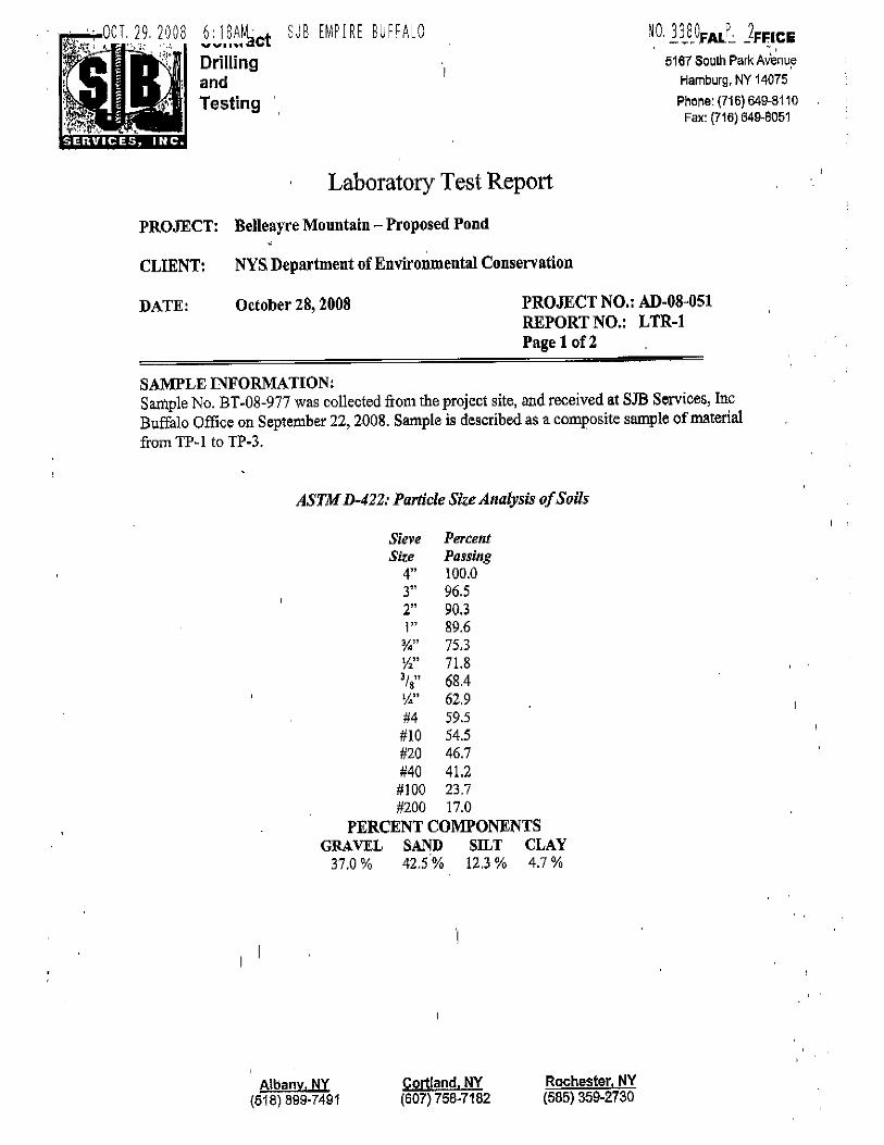
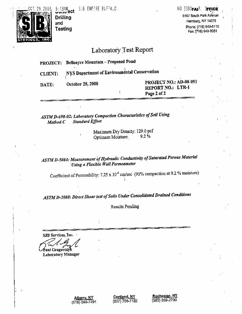
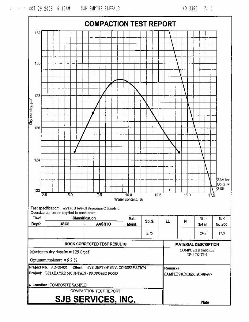
• ASTM D-422, Particle Size Analysis of Soils• ASTM D-698-02, Laboratory Compaction Characteristics ofSoil Using Method C Standard
Effort• ASTM D-5084, Measurement ofHydraulic ConductivityofSaturatedPorous Material Using
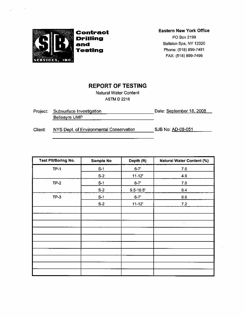
a Flexible Wall Permeameter• ASTM D-3080, Direct Shear Test of Soils Under Consolidated Drained Conditions• ASTM D-2216, Natural Water Content
Results of the field and laboratory testing program are presented in Attachment 4.
RESULTS OF INVESTIGATION
Subsurface Profile:The site was generally found to be mantled with sands and gravels with trace to some amounts ofsilt to depths of 19 to 24 feet, this sequence being ofa fum to compact relative density. Below this,very compact basal glacial till was encountered, as exhibited by coarser sands and gravels embeddedin a matrix of silt and fine sand (in the test pits, the transition to till was interpreted as beingshallower than that indicated by the test borings, generally at the depth at which color changed fromorange-brown to brown or where digging became more difficult; for the purposes ofthis report, theseupper soils are considered silty sands and gravels). Coarse augering, boulders and cobbles werecommonly noted throughout the overburden soils, likely resulting in elevated blow counts in someinstances. Underlying the till, sandstone bedrock was encountered at B-5, B-6 and B-7 at depths of33.5 feet, 23.8 feet and 25.0 feet respectively, as evidenced by auger refusal and confirmatory rockcoring at each location.
These fmdings are in general agreement with published information reviewed for this investigativesummary. The Soil Survey of Ulster County, New York (U.S. Department of Agriculture, 1979)maps surficial soils (generally representative of the upper six feet) in the area as either Wellsboroand Wurtsboro very bouldery soils, gently sloping, or Lackaw3lUla and Swartswood very boulderysoils, moderately steep. The survey describes these map units in terms of their sandy and gravellyloam (and bouldery) compositions, and as being moderately well to well drained. The soil surveyalso identifies certain limitations associated with each soil unit for selected uses, for considerationin site selection and design. In this regard, "large stones" are listed as a limitation with respect tothe suitability of site soils for the construction of embankments, dikes and levees, while "slope"limits the use ofthe moderately steep Lackaw3lUla and Swartswood unit in the construction ofpondreservoir areas. The shrink-swell potential of these soils is listed as low, while soil erodibilty "K"factors range from 0.20 to 0.28, indicating low to moderate erosion potential.
Bedrock in the area, as mapped on the Geologic Map of New York State, Hudson-Mohawk Sheet(State Education Department, 1970), is described as shale and sandstone conglomerate ofthe lowerWalton formation. All rock types exhibit a broad range of compressive strengths reflecting theirheterogeneity in composition and structure; it is estimated that compressive strengths associated withthe sandstone recovered in this investigation range from about 1,000 pounds per square inch (psi)to 15,000 psi or more, depending on the extent ofweathering and other factors affecting its structuralintegrity.
Groundwater Conditions:
Groundwater was not encountered in significant quantity in the test borings. Recovered soil sampleswere for the most part damp or moist, and wet soils were not recovered. At most locations, waterwas introduced into the borehole for either permeability tests or rock coring, and some measurableresidual water was therefore present in the borehole upon completion ofsampling at these locations.No groundwater was noted in the test pits.
Field and Laboratory Testing:
Permeability testing indicates that the upper sand and gravel soils exhibit hydraulic conductivity onthe order oflO-4 tolO-5 centimeters per second (em/sec), while that ofthe deeper basal till soils is onthe order of10-6 em/sec. These values represent relative permeabilities in the range ofsemi-perviousto impervious (Bear, 1972).
Natural water contents of the individual test pit samples ranged from 4.6 to 7.6 percent. Testing ofthe test pit composite sample indicates its maximum dry density is 129.0 pounds per cubic foot (pcf)at an optimum moisture content of 9.2 percent. Based on mechanical analysis of the sample, itsuses classification is SM, and its uniformity coefficient (0601010) is 466. The direct shear testindicates a peak friction angle of35 degrees, and peak cohesion of0.1 pounds per square inch (psi).Published reference material indicates the reported angle of internal friction is within the range ofexpected values for this type ofmaterial (NAVFAC DM 7.01). Note that the laboratorypermeabilityand direct shear results were obtained on .samples compacted to a target dry density of 122.6 pcf,approximately 95 percent ofmaximum dry density.
CONCLUSIONS AND RECOMMENDATIONS
Soil Properties and Design Parameters:
It appears that cuts up to 25 feet and fills upwards of 28 feet will be necessary to establish theproposed grades. Where cuts are required, the displaced material should generally consist of siltysands and gravels (as represented by the composite laboratory sample) which are suitable for re-useas embankment fill, with some limitations. Most notably, re-use of the prevalent cobbles andboulders in this material should be avoided. In order to achieve proper compaction of theembankment materials as they are placed, oversize material (larger in any dimension than thespecified compacted lift thickness) must be removed. We would recommend that lift thickness doesnot exceed 12 inches; depending on the size and effectiveness of the compaction equipment used,
smaller lift thickness may be necessary. The natural moisture content ofexcavated materials shouldallow them to be adequately compacted as they are placed, although some adjustment to moisturecontent may be necessary depending on prevailing weather conditions at the time of construction.
Deeper cuts (in excess of 20 feet or so) will likely encounter basal till materials, to some extent.These soils, while quite dense in their natural condition, may prove more difficult to work with intheir re-use as embankment fill, as they consist of a greater fractional component of fines ascompared with the upper soils. As such, they will likely exhibit greater moisture sensitivity, therebylimiting the ease in which proper compaction can be achieved. Additionally, the parameters derivedfrom the laboratory testing program are not necessarily representative of this material. If these tillsoils are encountered in significant quantity, and if their re-use as embankment fill is intended,additional laboratory testing should be perfonned to establish parameters specific to this material.Such testing should include ASTM D-422, Particle Size Analysis of Soils and ASTM D-698-02,Laboratory Compaction Characteristics of Soil Using Method C Standard Effort, at a minimum.
At location B-6, it is noted that the planned finished grade is near in elevation to where the bedrocksurface was found, at elevation 1906.8 feet. While the need for extensive rock excavation across thesite is not anticipated, the preceding example demonstrates that bedrock may be encountered nearor above planned grades inplaces. The publication GuidelinesforDesign ofDams (NYSDEC, 1985;revised 1989) cautions against exposing pervious soils or fissured rock at borrow areas withinproposed reservoir areas, and recommends that any such areas encountered be sealed with at leasttwo feet of compacted impervious material.
Based on our findings, the following soil parameters can be used for design of the earthenembankment dam, cognizant of the limitations described above:
Recommended Soil Parameters for Earthen Embankment Dam:
• Angle of Internal Friction - 35 degrees
• Cohesion - 0.1 psi (negligible)
• Penneability - 1.0 x 10⁻⁴ cm/sec
• Unifonnity Coefficient - 466
• Bearing Capacity - 10,000 psf*
• Coefficient of Friction - 0.7
* Nominal bearing capacity for generalized embankment foundation (min. 20 feet width)
The calculated uniformity coefficient of466 indicates the silty sand and gravel overburden soils arewell-graded. With respect to embankment construction, well-graded soils are preferable to soilshaving relatively unifonn particle size, as the fonner are usually stronger, less susceptible to piping,erosion and liquefaction, and less compressible, other factors being equal (U.S. Army Corps ofEngineers, 2004, publication EM 1110-2-2300).
It should be noted that excavation of the coarse materials revealed in the subsurface investigationmaybe relatively difficult. Frequent boulders and cobbles were noted throughout the test borings andtest pits. It is estimated that one-quarter to one-third ofthe excavated materials may be oversize andtherefore not suitable for re-use as embankment fill Plans should include a suitable borrowmaterial/source if a net deficit is anticipated with respect to cuts and fills.
As embankment fill materials are placed, compacted layers should be firm, stable, and free of anyoversize material, loose soil, mud, water or frost. It is not expected that generalized groundwaterconditions will be encountered in excavations, although it is possible some localized perched ortrapped seepage could be present depending on precipitation and seasonal conditions at the time ofconstruction. Such conditions, ifencountered, should be handled with conventional sump and pumpmethods to maintain construction in the dry.
CLOSURE
This report was prepared to assist in planning for design and construction of a water storage pondfor the Belleayre Mountain ski area in the town of Shandaken, New York. The design parametersand recommendations were developed based on Empire's understanding ofthe project, as describedherein, and through the application ofgenerally accepted soils and foundation engineering practice.No other warranties, expressed or implied, are made. Should there be any changes in the plannedconstruction, Empire should be notified to determine ifrevisions to the recommendations containedherein are required. Important information regarding the use and interpretation of this report isattached.
Sincerely,Empire-Geo Services, Inc.
dru-~-sJohn S. Hutchison, P.E.Geotechnical Engineer
John 1. Danzer, P.E.Senior Geotechnical Engineerand Project Reviewer
PROJECT: Subsurface Investigation LOCATION: Town of Shandaken
Belleayre UMP Ulster County, New York
OEPTH ~ BLOWS ON SAMPLERREC. SOIL OR ROCKIg NOTES
(ft.) (ft.) CLASSIFICATION016 6112 12118 18124 N
1/ 1 3 6 8 10 14 1.2 " TOPSOIL +1- 0.4' / Driller notes coarse --Brown SAND and GRAVEL, little to some silt (Damp - Firm) material in upper 13'. -
V2 52 29 26 22 55 1.4 Red Brown GRAVEL and silty SAND to 2.5', then Brown Augered through or past --SAND and GRAVEL, trace to little silt (Dry - Very Compact) boulder @ 9' - 10'. -
V3 17 23 24 52 47 1.6 - Similar; Gray Brown (Dry - Compact) Becomes less coarse -f-5-thereafter. -
V4 18 19 17 18 36 1.7 Brown Gray fine to coarse SAND, Some Gravel, trace silt ---
1/ 5 13 17 1001.2 - - 0.8 Brown Gray SAND and GRAVEL, trace silt -- r-- (Dry - Very Compact)f-10 -
V9 40 24 31 38 55 1.8 Brown TILL: Reddish Brown SILT and fine SAND with Water level at 36.8'- upon completion of rock -
embedded coarser sand, occasional gravel and rock coring, hole open to -- fragments. 38.5'. -- (Moist - Very Compact) -
Hole backfilled wIf-30 bentonite chips 38.5' to -
V10 65 31 45 50 76 1.6 TILL: Reddish Light Brown fine SAND and SILT, intermixed- 33.5', then tremie grout -with coarser sand, gravel, rock fragments wI bentonite slurry to -
- (Damp - Very Compact) surface. -11 1001.1 - - - - <0.1 ....... Rock fraQments in shoe (sandstone) (Dry - Very Compact) / Hole is dry before coring -
f-35Gray SANDSTONE, medium hard to hard, weathered, thin NO Core Run -bedded to bedded, occasional medium to high angle Run #1: 33.5' - 38.5' -fractures noted with reddish clayey soil (thin seams) at REC =92% (4.6') -
ROD =25% (1.25') --
End of Boring @ 38.5'..... 40
N =NO. BLOWS TO DRIVE 2-INCH SPOON 12-INCHES WITH A 140 LB. PIN WT. FALLING 30-INCHES PER BLOW CLASSIFICATION: Visual by
DRILLER: Tom Farrell DRILL RIG TYPE: CME 550x Geotechnical Engineer
METHOD OF INVESTIGATION: 41/4" Hollow Stem Augers, 3" (NW) Casing w/Diamond Bit, 2-15/16" Roller Bit, and NO Dual Tube Core Barrel
All recovered samples will be retained for approximately sixty (60) days, at which time the samples will be discarded unlessdirected otherwise.
- II 2 19 34 28 30 62 1.8 Gray Brown fine to coarse SAND and cobblefboulder casing installed to 23.8'; -fragments @ 2.5' (Dry - Very Compact) 2-15/16" roller-bit to 24.5'. _
I 3 20 23 27 31 50 1.7 Brown SAND and GRAVEL, little silt -~5-
(Moist - Compact) No measureable ground- -
II 4 35 29 30 33 59 1.9 - Similar; very compact water in hole prior to ---
- 1/ 5 17 36 33 30 69 1.6 - Similar; grades to little to some silt -Water level at 22.5' upon -~10
- I 6 16 22 27 40 49 1.5 Brown fine to coarse SAND, little gravel and silt completion of coring, -(Moist - Compact) hole open to 29.5'. -
- -- -
~15 -- ~I
7 15 10 13 15 23 1,7 - Similar; grades to some Gravel -(Moist - Firm) -
- -USCS: SM-GM +/- 19'
- -~20 -
- :; 8 21 37 36 34 73 1.8 TILl: Reddish Brown fine SAND and SILT intermixed with -coarser sand, gravel, rock fragments -
- (Damp - Very Compact) -= 9 50/.0 - - - - 0,0 - No Recovery +/- 24.5'- -
~25 -Gray SANDSTONE, medium hard to hard, lightly weathered, NO Core -thin bedded to bedded, near vertical fractures noted Run #1: 24,S' - 29.5' -from 26,S' to 27,5', REC =92% (4.6') -
ROD =69% (3.45') --30- -
- End of Boring @ 29.5'Hole backfilled w/ -
- bentonite chips 29.5' -- to 24.5', then tremie -- grout wI bentonite
-
-35-slurry to surface.
-- -- -
- -- -
-40
N = NO. BLOWS TO DRIVE 2-INCH SPOON 12-INCHES WITH A 140 LB. PIN WT. FALLING 30-INCHES PER BLOW CLASSIFICATION: Visual by
DRILLER: Tom Farrell DRILL RIG TYPE: CME 550x Geotechnical Engineer
METHOD OF INVESTIGATION: 41/4" Hollow Stem Augers, 2-15/16" Rollerbit, NO Core
All recovered samples will be retained for approximately sixty (60) days, at which time the samples will be discarded unlessdirected otherwise.
PROJECT: Subsurface Investigation LOCATION: Town of Shandaken
Belleayre UMP Ulster County, New York
DEPTH ~gBLOWS ON SAMPLER
REC. SOil OR ROCK NOTES(ft.) (ft.) CLASSIFICATION
016 6112 12118 18124 N
~ 1 48 1001.2 - - - 0.4 Reddish Brown SAND, GRAVEL and Boulder (rock?) r --- fragments. trace to little silt
Hole backfilled wi -(Damp-Ve~Compact) bentonite chips from --
-End of Boring @ 40.7' 40.7' to 35.0', then -
-45-tremie grout wi bentonite _slurry to surface.
- -- -
- -- -
-50- -- -- -- -- -
-55- -- -- -
- -- -
f-60- -- -- -- -
- -...... 65- -
- -- -- -- -
f-70- -- -- -
- -- -
...... 75- -- -- -
- -- -
--80
N =NO. BLOWS TO DRIVE 2-INCH SPOON 12-INCHES WITH A 140 LB. PIN WT. FAlLING 30·INCHES PER BLOW CLASSIFICATION: Visual by
DRILLER: Tom Farrell DRILL RIG TYPE: CME 550x Geotechnical Engineer
METHOD OF INVESTIGATION: 41/4" Hollow Stem Augers
All recovered samples will be retained for approximately sixty (60) days, at which time the samples will be discarded unlessdirected otherwise.
''''lC~"if.RVICr ........... C.
ContraotOr.llingandTeallna TEST PIT LOG
DATE: September 17, 2008
PROJ ECT: Subsurface InvestigationBelleayre UMP
CONTRACTOR: SJB Services, Inc.
FIELD GEOLOGIST: James Vincent, CPG
TEST PIT NO.:
G.S. ELEVATION:
PROJECT NO.:
TP-1
1927.30'
AD-08-051
WEATHER I TEMP.:EXCAVATION EQUIP.: Rubber-Tire Backhoe John Deere 410E
Sunny & Cool
DEPTH SOIL DESCRIPTION
o-2' Topsoil w/numerous roots & cobbles
2' - 6' Orange-Brown fine to medium SAND and GRAVEL, little siltw/numerous sandstone cobbles and occassional tabular sandstoneboulders (length 2' - 3' and 2" - 8" thick)
6' - 12' GLACIAL TILL: Brown GRAVEL and fine to medium SAND, trace siltw/numerous tabular sandstone cobbles and boulders(approx 30% to 40%)
L:\Mary\123\sublogs\AD-08-051\TP1
EXCAV. EFFORT
Moderate - Compact
Moderate - Compact
Hard - Very Compact
'i,9,O;." ~ .Cit UVI<:I. ...... "<le
contraotDrillingandTeatlng TEST PIT LOG
DATE: September 17. 2008
PROJECT: Subsurface InvestigationBelleayre UMP
CONTRACTOR: SJ8 Services, Inc.
FIELD GEOLOGIST: James Vincent, CPG
TEST PIT NO.:
G.S. ELEVATION:
PROJECT NO.:
TP-2
1910.41'
AD-08-051
WEATHER I TEMP.:EXCAVATION EQUIP.: Rubber-Tire Backhoe John Deere 410E
Sunny & Cool
DEPTH SOIL DESCRIPTION
0-1.5' Topsoil w/numerous tree roots &occasional cobbles
1.5' - 3.5' Orange-Brown fine to medium SAND and GRAVEL, little siltw/numerous tabular sandstone cobbles
3.5' - 10.5' SANDY TILL: Brown GRAVEL and fine to medium SAND, trace siltw/numerous (+/- 30% - 40%) tabular cobbles and boulders(1 r - 2' length and 2" - 8" thick).
L:\Mary\123\sublogs\AD-08-051 \TP 1
EXCAV. EFFORT
Moderate - Compact
Moderate - Compact
Hard - Very Compact
contraotDrillingandTeatlng TEST PIT LOG
DATE: September 17, 2008
PROJECT: Subsurface InvestigationBelleayre UMP
CONTRACTOR: SJB Services, Inc.
FIELD GEOLOGIST: James Vincent, ePG
TEST PIT NO.:
G.S. ELEVATION:
PROJECT NO.:
TP-3
1932.22'
AD-08-051
WEATHER I TEMP.:EXCAVATION EQUIP.: Rubber-Tire Backhoe John Deere 410E
Sunny & Cool
DEPTH SOIL DESCRIPTION
0- 1.0' Topsoil w/small roots
1.0' - 12.5' SANDY TILL: Brown GRAVEL and fine to medium SAND, trace siltw/numerous tabular sandstone cobbles and boulders(1'. 2'Iength and 2"·6" thick); less silt noted from 11.0' -12.5'.
L:\Mary\123\sublogs\AD-08-051\TP1
EXCAV. EFFORT
Moderate - Compact
Hard - Very Compact
, ,
DATE PROJ.No. AE-01-099
STARTED 7/29/01 SJB SERVICES, INC. HOLE No. B-1
FINISHED 7/30/01 SUBSURFACE LOG SURF. ELEV. 325.6
G.W. DEPTH see notesSHEET 1 OF 1
PROJECT LOCATION
BLOWS ONSAMPLER SOIL OR ROCK
CLASSIFICATION
3" TOPSOILBrown SILT, some Sand, trace clay, ML(Moist-Loose)
Gray SHALE, medium hard, weathered,thin bedded, some fractures
~ (numbem features 8explained on reverse)
NOTES
Groundwater at 10'upon completion, and5' 24 hrs. aftercompletion
I Runtl, 2.5'-5.0'®95% Recovery \.-.50% RQD ~
The following terms are used in classifying soilsconsisting of mixtures of two or more soil types.The estimate is based on weight of total sample.
(When sampling gravelly soils with a standard splitspoon, the true percentage of gravel is often notrecovered due to the relatively small samplerdiameter.)
TABLE I
0 Split SpoonSample
~Shelby TubeSample
~GeoprobeMacro-Core
ill Auger or TestPit Sample
I Rock Core
TABLE IV
TABLE IIIdentification of soil type is made on basis of an estimateof particle sizes, and in the case of fine grained soilsalso on basis of plasticity.
SAMPLE INFORMATION:Sample No. BT-08-977 was collected from the project site, and received at SJB Services, IncBuffalo Office on September 22, 2008. Sample is described as a composite sample of materialfrom TP~l to TP-3.
Location: Fi Ie No.: BT-08-977Date: 10/24/08 Lob No.: BT-08-977
PERMEASILITY TEST REFORTTested by: P9Checked by: pg
SJB SERVICES, INC. Test: CV - Constont vol ume
GeoTestingexpressa subsidiary of Geocomp·Corporation
Client: SJB Services, Inc.
Project Name: Belleayre Mountain - Proposed Pond
Project Location: Highmount, NY
GTX #: 8627
Start Date: 10/31/08 Tested By: bfs
End Date: 11/04/08 Checked By: rmt
Soil ID: BT-08-977 (TP-1 to TP-3)
5011 Description: Moist, olive gray slit with gravel
Direct Shear Test Series by ASTM D 3080
Soil Preparation: Target Compaction: 122.6 pcf at 9.2% moisture content (values provided by client).
Compaction Characteristics: MaxImum Dry Density --- pcf
Optimum Moisture Content --- 0/0
Compaction Test Method ---
Test Equipment: Top box = 12 in x 12 in; Bottom box = 16 in x 12 In; Load cells and LVDTs connected todata acquisition system for shear force, normal load and horizontal displacement readings;
surface area = 144 in2
Maximum Particle Size Used, in: 1.5 Horizontal Displacement, in/min: 0.02
Soil Height, in: 3 Test Condition: inundated
Gap Between Boxes, in: 1
Parameter Point 1 Point 2 Point 3 Point 4 Point 5 Point 6
Empire Geo-Services, Inc. (Empire) has endeavored to meet the generally accepted standard of c~e. fo~ theservices completed, and in doing so is obliged to advise the geotechnical report user of our report lumtatlons.Empire believes that providing information about the report preparation and limitations is essential to help theuser reduce geotechnical-related delays, cost over-runs, and other problems that can develop during the designand construction process. Empire would be pleased to answer any questions regarding the following limitationsand use of our report to assist the user in assessing risks and planning for site development and construction.
PROJECT SPECIFIC FACTORS: The conclusions and recommendations provided in our geotechnicalreport were prepared based on project specific factors described in the report, such as size, loading, and intendeduse of structures; general configuration of structures, roadways, and parking lots; existing and proposed sitegrading; and any other pertinent project information. Changes to the project details may alter the factorsconsidered in development of the report conclusions and recommendations. Accordingly, Empire cannot acceptresponsibility for problems which may develop if we are not consulted regarding any changes to the projectspecific factors that were assumed during the report preparation.
SUBSURFACE CONDITIONS: The site exploration investigated subsurface conditions only at discrete testlocations. Empire has used judgement to infer subsurface conditions between the discrete test locations, and onthis basis the conclusions and recommendations in our geotechnical report were developed. It should beunderstood that the overall subsurface conditions inferred by Empire may vary from those revealed duringconstruction, and these variations may impact on the assumptions made in developing the report conclusions andrecommendations. For this reason, Empire should be retained during construction to confirm that conditionsare as expected, and to refine our conclusions and recommendations in the event that conditions areencountered that were not disclosed during the site exploration program.
USE OF GEOTECHNICAL REPORT: Unless indicated otherwise, our geotechnical report has beenprepared for the use of our client for specific application to the site and project conditions described in thereport. Without consulting with Empire, our geotechnical report should not be applied by any party to othersites or for any uses other than those originally intended.
CHANGES IN SITE CONDITIONS: Surface and subsurface conditions are subject to change at a project sitesubsequent to preparation of the geotechnical report. Changes may include, but are not limited to, floods,earthquakes, groundwater fluctuations, and construction activities at the site and/or adjoining properties. Empireshould be informed of any such changes to determine if additional investigative and/or evaluation work iswarranted.
MISINTERPRETATION OF REPORT: The conclusions and recommendations contained in ourgeotechnical report are subject to misinterpretation. To limit this possibility, Empire should review project plansand specifications relative to geotechnical issues to confirm that the recommendations contained in our reporthave been properly interpreted and applied.
Subsurface exploration logs and other report data are also subject to misinterpretation by others if they areseparated from the geotechnical report. This often occurs when copies of logs are given to contractors duringthe bid preparation process. To minimize the potential for misinterpretation, the subsurface logs should not beseparated from our geotechnical report and the use ofexcerpted or incomplete portions ofthe report should beavoided.
OTHER LIMITATIONS: Geotechnical engineering is less exact than other design disciplines, as it is basedpartly on judgement and opinion. For this reason, our geotechnical report may include clauses that identify thelimits of Empire's responsibility, or that may describe other limitations specific to a project. These clauses areintended to help all parties recognize their responsibilities and to assist them in assessing risks and decisionmaking. Empire would be pleased to discuss these clauses and to answer any questions that may arise.