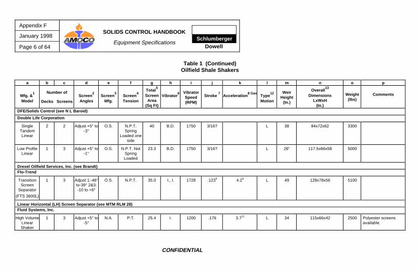
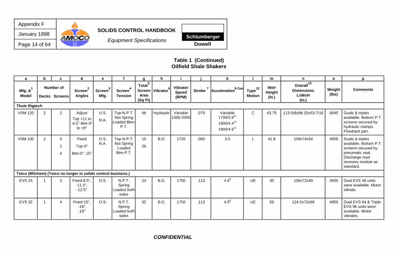
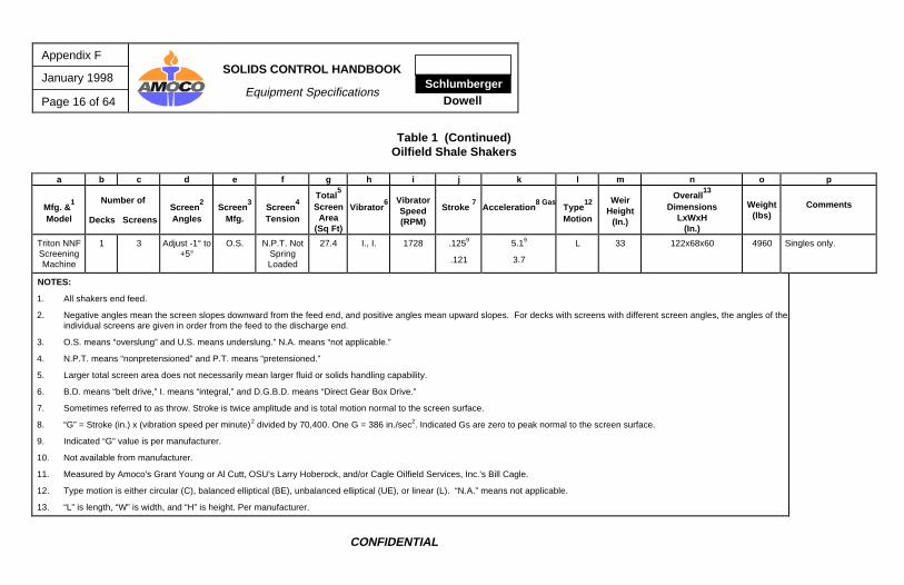
2. Negative angles mean the screen slopes downward from the feed end, and positive angles mean upward slopes. For decks with screens with different screen angles, the angles of theindividual screens are given in order from the feed to the discharge end.
3. O.S. means “overslung” and U.S. means underslung.” N.A. means “not applicable.”
4. N.P.T. means “nonpretensioned” and P.T. means “pretensioned.”
5. Larger total screen area does not necessarily mean larger fluid or solids handling capability.
6. B.D. means “belt drive,” I. means “integral,” and D.G.B.D. means “Direct Gear Box Drive.”
7. Sometimes referred to as throw. Stroke is twice amplitude and is total motion normal to the screen surface.
8. “G” = Stroke (in.) x (vibration speed per minute)2 divided by 70,400. One G = 386 in./sec2. Indicated Gs are zero to peak normal to the screen surface.
9. Indicated “G” value is per manufacturer.
10. Not available from manufacturer.
11. Measured by Amoco's Grant Young or Al Cutt, OSU’s Larry Hoberock, and/or Cagle Oilfield Services, Inc.'s Bill Cagle.
12. Type motion is either circular (C), balanced elliptical (BE), unbalanced elliptical (UE), or linear (L). “N.A.” means not applicable.
13. “L” is length, “W” is width, and “H” is height. Per manufacturer.
SchlumbergerDowell
SOLIDS CONTROL HANDBOOK
Equipment Specifications
Appendix F
January 1998
Page 17 of 64
CONFIDENTIAL
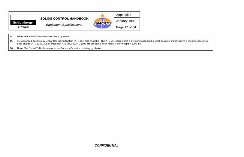
14. Measured at 80% of maximum eccentricity setting.
15. 15. Advanced Technology Linear Cascading System (ATL-CS) also available. The ATL-CS incorporates a circular motion double-deck scalping shaker above a linear motion singledeck shaker (ATL-1100). Deck angles for ATL-1000 & ATL-1100 are the same. Weir height = 80" Weight = 8000 lbs.
16. Note: The Retro FS Basket replaces the Tandem Basket on existing rig shakers.
Brandt TandemDahlory 147Demco TandemGeolograph-Pioneer STHarrisburg TandemHutchison Hayes 101 & 201-STNL Bariod SM IISwaco Super ShakerSweco TandemTotco EVS 24
Brandt Retrofit FSBrandt Total Flow CleanerDerrick StandardFlo-Trend Floline SeparatorNL Bariod Double DeckOiltools Tandem 800ASwaco Super ScreenTotco EVS 32Totco MudMasterTri-Flo TFI-146
Brandt ATL1000Broadbent DT-2000Cagle Linear ScreenCagle Ultra-ScreenDahlory 139Derrick LPDerrick Flo-Line CleanerDerrick Flo-Line Cleaner (+)Derrick Flo-Line Cleaner Model 58Double like Single Tandem LinearDouble like Low Profile LinearFlo-Trend Transition Screen Separator (FTS 3600L)Flo-Trend Linear Horizontal Screen SeparatorFluid Systems High Volume Linear ShakerHarrisburg Linear Tandem RetrofitHutchison Hayes QuadraflowQuality QLM-1MTM RLM 28Schiffner Super SifterSwaco Adjustable Linear ShakerSweco Full-Flo LM-3Sweco OilmizerThule VSM 100Thule VSM 120Tri-Flo TFI-148 MTTriton NNF Screening Machine
Note: The above classifications are general and are based on design and performance. In special flow rate, plugging, and/or viscosity situations, any of the above shakers could probably run finer or coarserscreens than indicated.
SchlumbergerDowell
SOLIDS CONTROL HANDBOOK
Equipment Specifications
Appendix F
January 1998
Page 19 of 64
CONFIDENTIAL
Table 3 Oilfield Centrifugal Pumps 1
a b c d e f g h i j k l m n
Mfg. &Model
ImpellerSize Range
(in.)
CasingDesign
Materials ofConstr.
Lubrication
Shaft 6
Sealing
Shaft SizeCouplingEnd/Thru
Packing (in.)
Required Impeller Size (in.) & Horsepower for 500 gpm &75 ft of Head for Various RPM’s Mud Weights
Impeller Horsepower (RPM) Size Water 10 ppg 14 ppg18 ppg
Comments
Baker Huges Pumps 2,3,4,5
1780 Series (equivalent to Mission Type W pumps)
2500 Series (equivalent to Mission Magnum 1 pump)
3000 Series (Formerly Galigher Pumps)
5x6(5x6x11)
9-11 Circular Cast Iron,Elastomer
Lined11
Oil Bath C.P.4 1-7/8/3.0 1150
1750
>11”9"
N.A.
18.0
N.A.
21.5
N.A.
30.2
N.A.
38.8
Impeller locked on or threaded.Clockwise rotation only.13
6x8(6x8x14)
11-14 Circular Cast Iron,Elastomer
Lined11
Oil Bath C.P.4 1-7/8/3.0 1150 12.25 21 25.2 35.3 45.4 Impeller locked on or threadbare on.Clockwise rotation only.13
BJ Hughes 3
5"(5x6x13.5)
9-13.59 Volute Cast Iron Grease C.P. 1-13/16/1-13/16 1150
1750
13.5
9
14.0
15.5
16.8
18.6
23.5
26.1
30.3
33.5
Suction line should never be smallerthan suction inlet. Discontinuedmanufacturing.
6"(6x8x14.5)
10-14.59 Volute Cast Iron Grease C.P. 1-13/16/1-13/16 1150
1750
13.25
<10"
15.5
N.A.
18.6
N.A.
26.1
N.A.
33.5
N.A.
Suction line should never be smallerthan suction inlet. Discontinuedmanufacturing.
Appendix F
January 1998
Page 20 of 64
SOLIDS CONTROL HANDBOOK
Equipment Specifications Schlumberger
Dowell
CONFIDENTIAL
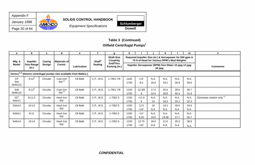
Table 3 (Continued)
Oilfield Centrifugal Pumps 1
a b c d e f g h i j k l m n
Mfg. &Model
ImpellerSize Range
(in.)
CasingDesign
Materials ofConstr.
Lubrication
Shaft 6
Sealing
Shaft SizeCouplingEnd/Thru
Packing (in.)
Required Impeller Size (in.) & Horsepower for 500 gpm &75 ft of Head for Various RPM’s Mud Weights
Impeller Horsepower (RPM) Size Water 10 ppg 14 ppg18 ppg
Comments
Demco 3,12 (Demco centrifugal pumps now available from Mattco.)
CP5x6
(5x6x12)
8-128 Circular Cast IronStd.11
Oil Bath C.P., M.S. 1-7/8/1-7/8 1150
1750
>12”
8.5
N.A.
16.0
N.A.
19.2
N.A.
26.9
N.A.
34.6
6x8(6x8x12)
8-128 Circular Cast IronStd.11
Oil Bath C.P., M.S. 1-7/8/1-7/8 1150
1750
12-3/8
9
17.0
24.0
20.4
28.8
28.6
40.3
36.7
51.9
XD4
5x6x118-11.5 Circular Hard Iron
Std.Oil Bath C.P., M.S. 1-7/8/2.5 1150
1750
>11.5
9
N.A.
15
N.A.
18.0
N.A.
25.2
N.A.
32.4
Clockwise rotation only.13
5x6x14 10-14 Circular Hard IronStd.
Oil Bath C.P., M.S. 1-7/8/2.5 1150
1750
12.5
<10"
16
N.A.
19.2
N.A.
26.9
N.A.
34.6
N.A.
6x8x11 8-11 Circular Hard IronStd.
Oil Bath C.P., M.S. 1-7/8/2.5 1150
1750
<11"
9.25
N.A.
16.5
N.A.
19.38
N.A.
27.7
N.A.
35.7
6x8x14 10-14 Circular Hard IronStd.
Oil Bath C.P., M.S. 1-7/8/2.5 1150
1750
12.75
<10"
18.0
N.A.
21.6
N.A.
30.3
N.A.
38.9
N.A.
SchlumbergerDowell
SOLIDS CONTROL HANDBOOK
Equipment Specifications
Appendix F
January 1998
Page 21 of 64
CONFIDENTIAL
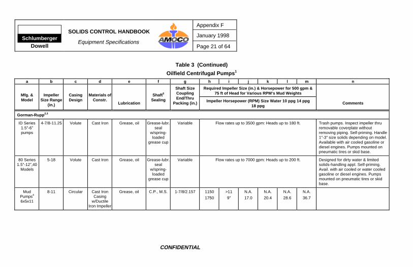
Table 3 (Continued)
Oilfield Centrifugal Pumps 1
a b c d e f g h i j k l m n
Mfg. &Model
ImpellerSize Range
(in.)
CasingDesign
Materials ofConstr.
Lubrication
Shaft 6
Sealing
Shaft SizeCouplingEnd/Thru
Packing (in.)
Required Impeller Size (in.) & Horsepower for 500 gpm &75 ft of Head for Various RPM’s Mud Weights
Impeller Horsepower (RPM) Size Water 10 ppg 14 ppg18 ppg
Comments
Gorman-Rupp 2,3
ID Series1.5"-6”pumps
4-7/8-11.25 Volute Cast Iron Grease, oil Grease-lubr.seal
w/spring-loaded
grease cup
Variable Flow rates up to 3500 gpm: Heads up to 180 ft. Trash pumps. Inspect impeller thruremovable coverplate withoutremoving piping. Self-priming. Handle1"-3” size solids depending on model.Available with air cooled gasoline ordiesel engines. Pumps mounted onpneumatic tires or skid base.
80 Series1.5"-12”,40
Models
5-18 Volute Cast Iron Grease, oil Grease-lubr.seal
w/spring-loaded
grease cup
Variable Flow rates up to 7000 gpm: Heads up to 200 ft. Designed for dirty water & limitedsolids-handling appl. Self-priming.Avail. with air cooled or water cooledgasoline or diesel engines. Pumpsmounted on pneumatic tires or skidbase.
MudPumps4
6x5x11
8-11 Circular Cast IronCasing
w/DuctileIron Impeller
Grease, oil C.P., M.S. 1-7/8/2.157 1150
1750
>11
9"
N.A.
17.0
N.A.
20.4
N.A.
28.6
N.A.
36.7
Appendix F
January 1998
Page 22 of 64
SOLIDS CONTROL HANDBOOK
Equipment Specifications Schlumberger
Dowell
CONFIDENTIAL
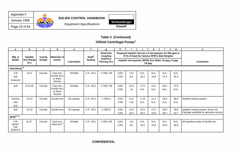
Table 3 (Continued)
Oilfield Centrifugal Pumps 1
a b c d e f g h i j k l m n
Mfg. &Model
ImpellerSize Range
(in.)
CasingDesign
Materials ofConstr.
Lubrication
Shaft 6
Sealing
Shaft SizeCouplingEnd/Thru
Packing (in.)
Required Impeller Size (in.) & Horsepower for 500 gpm &75 ft of Head for Various RPM’s Mud Weights
Impeller Horsepower (RPM) Size Water 10 ppg 14 ppg18 ppg
Comments
Harrisburg 3,9
178
5x6
(5x6x12)
9-12 Circular Cast Iron,Ductile Iron,
or Alum.Bronze
Oil Bath C.P., M.S. 1-7/8/1-7/8 1150
1750
>12
8.5
N.A.
16.3
N.A.
19.6
N.A.
27.4
N.A.
35.2
6x8 9-13.25 Circular Cast Iron,Ductile Iron,
or Alum.Bronze
Oil Bath C.P., M.S. 1-7/8/1-7/8 1150
1750
12.5
<9
17.5
N.A.
21.0
N.A.
29.4
N.A.
37.8
N.A.
Honcho
250
5x6
10-14 Circular Ductile Iron Oil, grease C.P., M.S. 1-7/8/2.5 1150
1750
12.5
<10
17.8
N.A.
21.4
N.A.
29.9
N.A.
38.5
N.A.
Impeller locking system.
6x8 10-14 Circular Ductile Iron Oil, grease C.P., M.S. 1-7/8/2.5 1150
1750
13.5
10.5
22.9
29.0
27.5
34.8
38.5
48.7
49.5
62.7
Impeller locking system. Extra Life Package available for abrasive service.
MCM4,7,12
178Series3
5x6(5x6x12)
8-127 Circular Cast Iron,Hard Iron11
Oil Bath C.P., M.S. 1-7/8/1-7/8 1150
1750
>12
8.5
N.A.
16.0
N.A.
19.2
N.A.
26.9
N.A.
34.6
All impellers made of ductile iron.
SchlumbergerDowell
SOLIDS CONTROL HANDBOOK
Equipment Specifications
Appendix F
January 1998
Page 23 of 64
CONFIDENTIAL
Table 3 (Continued)
Oilfield Centrifugal Pumps 1
a b c d e f g h i j k l m n
Mfg. &Model
ImpellerSize Range
(in.)
CasingDesign
Materials ofConstr.
Lubrication
Shaft 6
Sealing
Shaft SizeCouplingEnd/Thru
Packing (in.)
Required Impeller Size (in.) & Horsepower for 500 gpm &75 ft of Head for Various RPM’s Mud Weights
Impeller Horsepower (RPM) Size Water 10 ppg 14 ppg18 ppg
Comments
6x8(6x8x13)
9-13.257 Circular Cast Iron,Hard Iron11
Oil Bath C.P., M.S. 1-7/8/1-7/8 1150
1750
12.5
9
17.0
24.0
20.4
28.38
28.6
40.3
36.7
51.9
All impellers made of ductile iron.
250Series4
5x6x11
8-11.5
8-11.0
Circular Ductile Iron Oil Bath C.P., M.S. 1-7/8/2.5 1150
1750
>11.5
9
N.A.
15.0
N.A.
18.0
N.A.
25.2
N.A.
32.4
All 250 Series impellers are opendesign and right hand rotation only.
5x6x14 10-14 Circular Ductile Iron Oil Bath C.P., M.S. 1-7/8/2.5 1150
1750
12.5
<10
15.1
N.A.
18.1
N.A.
25.4
N.A.
32.6
N.A.
6x8x11 8-11 Circular Ductile Iron Oil Bath C.P., M.S. 1-7/8/2.5 1150
1750
>11
9.25
N.A.
17.0
N.A.
20.4
N.A.
28.6
N.A.
36.7
6x8x14 10-14.125
10-14
Circular Ductile Iron Oil Bath C.P., M.S. 1-7/8/2.5 1150
Grease Packless 1.75/N.A.10 1750 8.5 16.4 19.7 27.6 35.4 Type FS Packless self-priming pumpsalso available in 5" and 6" sizes.
6x6 R&C13 8.5-10.5 Circular Hard IronStd.
Grease Packless 1.75/N.A.10 ? ? ? ? ? ?
SchlumbergerDowell
SOLIDS CONTROL HANDBOOK
Equipment Specifications
Appendix F
January 1998
Page 25 of 64
CONFIDENTIAL
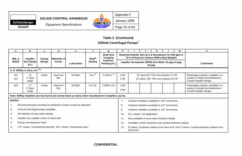
Table 3 (Continued)
Oilfield Centrifugal Pumps 1
a b c d e f g h i j k l m n
Mfg. &Model
ImpellerSize Range
(in.)
CasingDesign
Materials ofConstr.
Lubrication
Shaft 6
Sealing
Shaft SizeCouplingEnd/Thru
Packing (in.)
Required Impeller Size (in.) & Horsepower for 500 gpm &75 ft of Head for Various RPM’s Mud Weights
Impeller Horsepower (RPM) Size Water 10 ppg 14 ppg18 ppg
Comments
A. R. Wilfley & Sons, Inc. 4,11
ES
6x4
132" diamrange
Volute Hard IronStd.
Oil Bath N.A.10 2.12/N.A.10 1150
1750
13" gives 82' TDH and requires 17 HP
13" gives 196' TDH and requires 52 HP
Packingless design; available in avariety of metals and elastomers.Closed impeller design.
8x6 172" diamrange
Volute Hard IronStd.
Oil Bath N.A.10 2.38/N.A.10 1150
1750
Packingless design; available in avariety of metals and elastomers.Closed impeller design.
Note: Wilfley impellers are too hard to be turned down as many other manufacturer's impellers can be.
NOTES:
1. All horizontal-type mounted on pedestal or frame except as indicated.
2. Vertical centrifugal pumps available.
3. All impellers of semi-open design.
4. Impeller has expeller vanes on back side.
5. Pumps are elastomer lined.
6. C.P. means “conventional packing”; M.S. means “mechanical seal.”
7. Cutdown impellers available in 1/8” increments.
8. Cutdown impellers available in 1/4” increments.
9. Cutdown impellers available in 1/2” increments.
10. N.A. means “not applicable.”
11. Also available in more wear-resistant metals.
12. Available in both clockwise and counterclockwise rotation.
13. R means “clockwise rotation from drive end” and C means “counterclockwise rotation fromdrive end.”
Appendix F
January 1998
Page 26 of 64
SOLIDS CONTROL HANDBOOK
Equipment Specifications Schlumberger
Dowell
CONFIDENTIAL
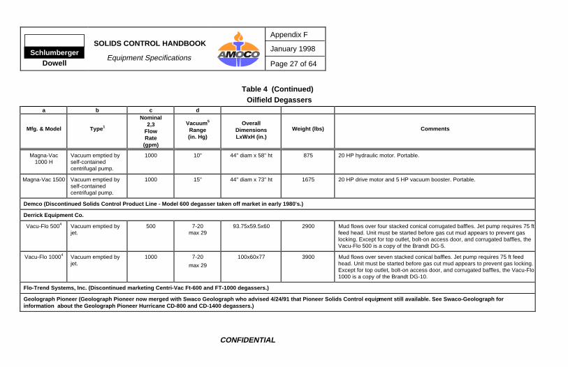
Table 4 Oilfield Degassers
a b c d
Mfg. & Model Type 1
Nominal2,3
FlowRate
(gpm)
Vacuum 5
Range(in. Hg)
OverallDimensionsLxWxH (in.)
Weight (lbs) Comments
Brandt
DG-54 Vacuum emptied byjet pump.
500 7-20max 29
88x54x62 2390 Mud flows over four stacked conical baffles (9956 in2 area). Jet pump requires75 ft feed head. All units must be started up before gas cut mud appears toprevent gas locking.
DG-104 Vacuum emptied byjet pump.
1000 7-20 100x60x77 3900 Mud flows over seven stacked conical baffles (32060 in2 area). Jet pumprequires 75 ft feed head.
500 10" 39" diam x 64" ht 1000 All units self-contained. All models designed to set down in mud tank. Allmodels designed to allow easy passage of lost circulation materials. All unitsdesigned to break down into two pieces for portability. All models have vacuumcreated by regenerative vacuum blower. All units have positive gas discharge.Gas separated by vacuum and turbulence. All units must have suction anddischarge submerged to start up. All units run noisy at approximately 85 db,and ear protection should be worn if working near for extended periods. 20 HPmotor.
1000 15" 44" diam x 73" ht 1675 20 HP drive motor and 5 HP vacuum booster. Portable.
Demco (Discontinued Solids Control Product Line - Model 600 degasser taken off market in early 1980's.)
Derrick Equipment Co.
Vacu-Flo 5004 Vacuum emptied byjet.
500 7-20max 29
93.75x59.5x60 2900 Mud flows over four stacked conical corrugated baffles. Jet pump requires 75 ftfeed head. Unit must be started before gas cut mud appears to prevent gaslocking. Except for top outlet, bolt-on access door, and corrugated baffles, theVacu-Flo 500 is a copy of the Brandt DG-5.
Vacu-Flo 10004 Vacuum emptied byjet.
1000 7-20
max 29
100x60x77 3900 Mud flows over seven stacked conical baffles. Jet pump requires 75 ft feedhead. Unit must be started before gas cut mud appears to prevent gas locking.Except for top outlet, bolt-on access door, and corrugated baffles, the Vacu-Flo1000 is a copy of the Brandt DG-10.
Flo-Trend Systems, Inc. (Discontinued marketing Centri-Vac Ft-600 and FT-1000 degassers.)
Geolograph Pioneer (Geolograph Pioneer now merged with Swaco Geolograph who advised 4/24/91 that Pioneer Solids Control equip ment still available. See Swaco-Geolograph for information about the Geolograph Pioneer Hurricane CD-800 and CD-1400 degassers.)
Appendix F
January 1998
Page 28 of 64
SOLIDS CONTROL HANDBOOK
Equipment Specifications Schlumberger
Dowell
CONFIDENTIAL
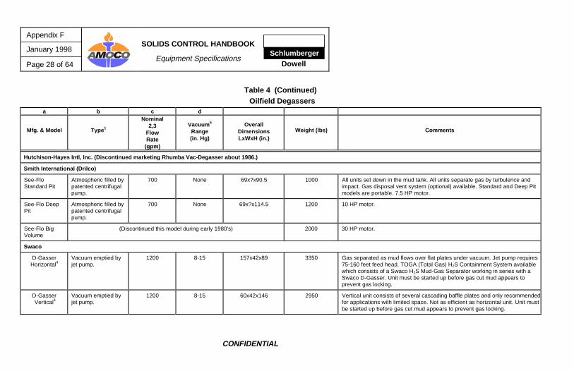
Table 4 (Continued)Oilfield Degassers
a b c d
Mfg. & Model Type 1
Nominal2,3
FlowRate
(gpm)
Vacuum 5
Range(in. Hg)
OverallDimensionsLxWxH (in.)
Weight (lbs) Comments
Hutchison-Hayes Intl, Inc. (Discontinued marketing Rhumba Vac-Degasser about 1986.)
Smith International (Drilco)
See-FloStandard Pit
Atmospheric filled bypatented centrifugalpump.
700 None 69x?x90.5 1000 All units set down in the mud tank. All units separate gas by turbulence andimpact. Gas disposal vent system (optional) available. Standard and Deep Pitmodels are portable. 7.5 HP motor.
See-Flo DeepPit
Atmospheric filled bypatented centrifugalpump.
700 None 69x?x114.5 1200 10 HP motor.
See-Flo BigVolume
(Discontinued this model during early 1980's) 2000 30 HP motor.
Swaco
D-GasserHorizontal4
Vacuum emptied byjet pump.
1200 8-15 157x42x89 3350 Gas separated as mud flows over flat plates under vacuum. Jet pump requires75-160 feet feed head. TOGA (Total Gas) H2S Containment System availablewhich consists of a Swaco H2S Mud-Gas Separator working in series with aSwaco D-Gasser. Unit must be started up before gas cut mud appears toprevent gas locking.
D-Gasser Vertical4
Vacuum emptied byjet pump.
1200 8-15 60x42x146 2950 Vertical unit consists of several cascading baffle plates and only recommendedfor applications with limited space. Not as efficient as horizontal unit. Unit mustbe started up before gas cut mud appears to prevent gas locking.
800 w/water none 42.5x37.5x103 1650 All Hurricane units designed to set down in the mud tank. Uses centrifugalforce to pump the fluid and to separate the gas. Used to deaerate muds thatinherently tend to foam. All Hurricane units originally developed by GeolographPioneer. All units compact and can be broken down for easy transport. 15 HPmotor.
Hurricane CD-1400
Atmospheric filled bycentrifugal pumpaction.
1400 w/water none 57.5x46.5x104 2400 25 HP motor.
Sweco
DG-2 Vacuum emptied bycentrifugal pump.
800 9-14 77x49x86 2400 Self-contained unit must set beside mud tank. Vacuum pump creates vacuumin the chamber. Gas separated by combination of centrifugal force, turbulence,and vacuum. No auxiliary pump required. Vacuum adjusted with a regulatorvalve. 15 HP motor.
Note: Sweco at one time marketed DG-3 and DG-4 degassers but has discontinued these two units and now only markets the DG-2.
VG-1 Vacuum emptied byjet pump.
1000 8-15 144x42x60 2200 Gas separated as mud flows over flat plates under vacuum. Unit must bestarted up before gas cut mud appears to prevent gas locking. Unit much likeSwaco Horizontal D-Gasser except vessel is slightly larger in diameter andvacuum pump and motor both located on the skid.
Appendix F
January 1998
Page 30 of 64
SOLIDS CONTROL HANDBOOK
Equipment Specifications Schlumberger
Dowell
CONFIDENTIAL
Table 4 (Continued)Oilfield Degassers
a b c d
Mfg. & Model Type 1
Nominal2,3
FlowRate
(gpm)
Vacuum 5
Range(in. Hg)
OverallDimensionsLxWxH (in.)
Weight (lbs) Comments
Thule Rigtech (Thule markets the Burgess Degasser.)
Tillett Tool Co.
Gas Hog Atmospheric filled byimpeller pump.
800-1000800 optimum
<2 42x42x125 or 150 1200&
1250
Unit sets down in tank. Mud pumped into chamber where a spinning diskdeflects the mud radially toward the wall over three sets of baffles. Gasseparated by impact and turbulence and removed by vacuum blower. Optionalblower available if gas is to be vented more than 200 ft away.
Totco (Discontinued Solids Control product Line.)
TSC-500 A4 Vacuum emptied byjet pump fed by self-priming centrifugalpump.
500 w/water 10-26
27 max
76x72x72 2200 Unit has microprocessor which monitors oil pressure inside the vacuum pump,liquid level inside the suction air scrubber and the load condition on both thevacuum pump and the centrifugal pump motor. If any of these conditionsexceed preset limits, the unit shuts down and indicates where the problem ison the control panel. Gas separated by turbulence, flow as thin sheet overbaffles, and vacuum. Unit must be started up before gas out mud appears toprevent gas locking.
Note: Totco at one time marketed Milchem's AV vacuum degasser but discontinued the AV in favor of the TSC-500 A.
Tri-Flo
Compact 800Degasser4
Vacuum emptied byjet pump.
600 Max 13 48x48x95 2600 Gas separated by vacuum over baffle plates. Gas being separated used toequalize the vacuum rather than air as with other manufacturer's units. All unitsmust be started up before gas cut mud appears to prevent gas locking.
SchlumbergerDowell
SOLIDS CONTROL HANDBOOK
Equipment Specifications
Appendix F
January 1998
Page 31 of 64
CONFIDENTIAL
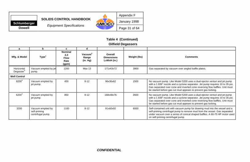
Table 4 (Continued)Oilfield Degassers
a b c d
Mfg. & Model Type 1
Nominal2,3
FlowRate
(gpm)
Vacuum 5
Range(in. Hg)
OverallDimensionsLxWxH (in.)
Weight (lbs) Comments
HorizontalDegasser4
Vacuum emptied by jetpump.
1200 Max 13 171x43x72 3900 Gas separated by vacuum over angled baffle plates.
Well Control
82004 Vacuum emptied byjet pump.
450 8-12 96x36x62 1500 No vacuum pump. Like Model 5200 uses a dual ejector venturi and jet pumpwith a 1.939" nozzle and a cyclone separator. Jet pump requires 10 to 35 psi.Gas separated over cone and inverted cone reversing flow baffles. Unit mustbe started before gas cut mud appears to prevent gas locking.
62004 Vacuum emptied byjet pump.
850 8-12 168x48x76 2600 No vacuum pump. Like Model 5200 uses a dual ejector venturi and jet pumpwith a 1.939" nozzle and a cyclone separator. Jet pump requires 10 to 35 psi.Gas separated over cone and inverted cone reversing flow baffles. Unit mustbe started before gas cut mud appears to prevent gas locking.
1100 8-12 91x60x92 6000 Self-contained unit with vacuum pump for drawing mud into the vessel and aself-priming centrifugal pump to remove mud from the vessel. Gas separatedunder vacuum over a series of conical shaped baffles. A 60-75 HP motor usedon self-priming centrifugal pump.
Appendix F
January 1998
Page 32 of 64
SOLIDS CONTROL HANDBOOK
Equipment Specifications Schlumberger
Dowell
CONFIDENTIAL
Table 4 (Continued)Oilfield Degassers
a b c d
Mfg. & Model Type 1
Nominal2,3
FlowRate
(gpm)
Vacuum 5
Range(in. Hg)
OverallDimensionsLxWxH (in.)
Weight (lbs) Comments
52004 Vacuum emptied byjet pump.
1100 8-12 156x60x72 3500 No vacuum pump. Uses a dual ejector venturi jet pump to draw mud into theunit by vacuum and to discharge the mud from the vessel. Gas separatedunder vacuum over four stacked conical baffles (9328 in2). Mud and gasmixture discharged by ejector through a cyclone separator which separates thegas out top and mud out bottom to active mud pit. Mud return line shouldextend down to one ft. above bottom of mud tank. Jet pump requires 35 to 55psi. Uses a 1.939" jet pump nozzle. Unit must be started up before gas cutmud appears to prevent gas locking.
NOTES:
1. Degassers are classified as either atmospheric or vacuum. To be classified as a vacuum degasser, a unit must maintain a continuous 5 in. of mercury vacuum.
2. Nominal flow rates given are for water. Flow rates for viscous muds are less. Flow rates for heavy, viscous gas cut muds are much less.
3. Values given are per manufacturer.
4. All vacuum units using jet pumps to discharge the mud must be started up before the gas cut mud appears to prevent gas locking.
5. The level of vacuum attained is a function of mud weight, mud viscosity, the height of the degasser above the mud surface, and the capability of the vacuum pump.
SchlumbergerDowell
SOLIDS CONTROL HANDBOOK
Equipment Specifications
Appendix F
January 1998
Page 33 of 64
CONFIDENTIAL
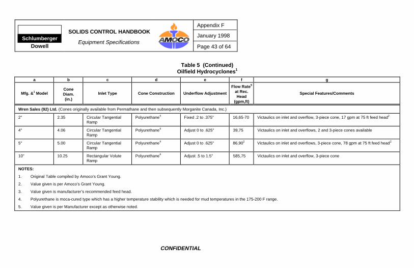
Table 5 Oilfield Hydrocyclones 1
a b c d e f g
Mfg. & 1 ModelConeDiam.(in.)
Inlet Type Cone Construction Underflow Adjustment
Flow Rate 5
at Rec.Head
(gpm,ft)
Special Features/Comments
Bailey-Parks Urethane, Inc. (Bailey-Parks builds cones for various oilfield solids control companies.)
2.5" 2.375 Rectangular TangentRamp
Polyurethane4 Fixed .125 & cutoff to.75"
6,45 1.25" Victaulics on inlet and overflow, 3-piece cone
4" 4.0 Rectangular TangentRamp
Polyurethane4 Adjust .125 to .50" 50,75 2" Victaulics on inlet and overflow, 2-piece cone
5" 5.0 Circular Tangent Polyurethane4 Adjust .25 to .75" 80,75 2" Victaulics on inlet and overflow, 2-piece cone
5" 5.0 Circular Tangent Polyurethane4 Adjust .25 to .75" 80,75 2" Flange on inlet; 2" Victaulic on overflow, 2-piece cone
10" 10.125 Rectangular Involute Polyurethane4 Adjust .75 to 1.25" 500,75 5" Victaulics on inlet and overflow, 3-piece cone
Baker Hughes Pumps
3" (same as MPE 3" 50 gpm cone with rectangular tangent entry)
4" 4.07 Circular Tangent Polyurethane Adjust .125 to .625" 50,32-38psi
Ceramic insert in apex area for wear resistance, victaulics on inlet andoverflow, 2-piece cone
5" 5.07 Circular Tangent Polyurethane Adjust .125 to .625" 80,32-38psi
Ceramic insert in apex area on inlet and victaulic on overflow, either flangedor victaulic, 2-piece cone
5" Victaulics on inlet and overflow, fixed apex acts as wear inserts, availablewith ceramic insert
Appendix F
January 1998
Page 34 of 64
SOLIDS CONTROL HANDBOOK
Equipment Specifications Schlumberger
Dowell
CONFIDENTIAL
Table 5 (Continued)Oilfield Hydrocyclones 1
a b c d e f g
Mfg. & 1 ModelConeDiam.(in.)
Inlet Type Cone Construction Underflow Adjustment
Flow Rate 5
at Rec.Head
(gpm,ft)
Special Features/Comments
Baker-Hughes Treatment Systems, Inc. (see NL Baroid)
Baroid (see NL Baroid)
Bird Machine Co. (see NL Baroid)
C. E. Bauer (Bauer manufactures a wide variety of cones of common and exotic materials for a wide variety of industrial users a nd has supplied cones to the oilfield.)
650,1152 400 gpm at 75 ft head2 Victaulics or Flanges
Brandt (Division of Drexel Oilfield Services, Inc.)
2" ? ? Polyurethane? Fixed? 20,75 ?2-piece cone, victaulics on feed and overflow, ceramic insert molded intoapex, manifolds available with 4-24 cones
4" 3.9 Rectangular Involute Polyurethane? Adjust .125 to .69" 66,752 2-piece cone, victaulics on feed and overflow, manifolds available with 1, 2,or 3 cones in either vertical or slant mounting
12" 12.2 Circular Involute Polyurethane? Fixed 1.5, 1.75, 2.125" 492,752 3-piece cone, victaulics on feed and overflow, manifolds available with 1, 2,or 3 cones in either vertical or slant mounting
SchlumbergerDowell
SOLIDS CONTROL HANDBOOK
Equipment Specifications
Appendix F
January 1998
Page 35 of 64
CONFIDENTIAL
Table 5 (Continued)Oilfield Hydrocyclones 1
a b c d e f g
Mfg. & 1 ModelConeDiam.(in.)
Inlet Type Cone Construction Underflow Adjustment
Flow Rate 5
at Rec.Head
(gpm,ft)
Special Features/Comments
Dahlory, Inc.
4" 3.9 Rectangular Tangent Polyurethane Adjustable .25 to .625" 55,75 Manifolds available with 2-20 4" cones, Victaulics on feed and overflow, 2-piece cone
10" 10.25 Rectangular Tangent Polyurethane Adjustable .5 to 1.75" 500,75 Manifolds available with 1, 2, or 3 10" cones, Victaulics on feed andoverflows, 3-piece cone
Demco (Discontinued Solids Control Product Line; see RETSCO for available Demco cones.)Derrick Equipment Co.
2" 2 Circular Tangent Polyurethane4 Adjust .25 to .50" 15,75 All Derrick 2", 3", and 4" cones are designed to fit the same manifold. 2“valves are standard on all circular manifolds optional for all in-line manifolds.
3" (same as MPE 3" 50 gpm cone with rectangular tangent entry)
4" 3.813 Circular TangentRamp
Polyurethane4 Adjust .25 to .56" 50,75 Polykineticurethane bottom liner, screws together, 2-piece cone, in-line orcircular manifolds available, 2" valves on inlets, victaulics on inlet andoverflow, manifolds available with 6-20 4" cones
DFE/Solids Control (see NL Baroid)Drilco (see Smith International)
Flo Trend Systems, Inc.2" (same as Bailey Parks 2.5"; see Bailey Parks)3" (same as Hydro-Separation Systems, Inc. 3" 50 gpm cone with rectangular tangent entry)
4" 4 Rectangular TangentRamp
Polyurethane4 Adjust 0 to .625" 62,752 Victaulics on feed and overflow, 2-piece cone, manifolds available with 4-204" cones
Appendix F
January 1998
Page 36 of 64
SOLIDS CONTROL HANDBOOK
Equipment Specifications Schlumberger
Dowell
CONFIDENTIAL
Table 5 (Continued)Oilfield Hydrocyclones 1
a b c d e f g
Mfg. & 1 ModelConeDiam.(in.)
Inlet Type Cone Construction Underflow Adjustment
Flow Rate 5
at Rec.Head
(gpm,ft)
Special Features/Comments
5" 4.9 Rectangular TangentRamp
Polyurethane4 Adjust 0 to .625"0 to .750"
102,752 Flange on inlet and victaulic on overflow, 2-piece cone; manifolds availablewith 4-20 5" cones
Geolograph-Pioneer (has merged with Swaco; see Swaco)
Harrisburg
4" 3.875 Circular Tangent Polyurethane4 Adjust 0 to .75" 50,75 Manifolds available with 8-24 cones, victaulics on feed and overflow, 2-piececone
5" 4.875 Circular Tangent Polyurethane4 Adjust 0 to .75" 80,75 Manifolds available with 8-20 cones, flange on inlet and victaulic onoverflow, 2-piece cone
10" 10.0 Rectangular Involute Polyurethane4 Adjust 0 to 1.5" 500,75 Manifolds available with 1-3 cones slant mounted and 1-2 cones verticallymounted, victaulics on inlet and overflow, 3-piece cone
Hutchinson Hayes International, Inc.
5" 4.77 Circular Tangent Polyurethane Adjust .25 to .5" 80,75 Manifolds available with 4-16 cones, flange on inlet and victaulic onoverflow, 2-piece cone
10" 10.2 Rectangular Involute Polyurethane Fixed 1, 1.25, 1.50" 500,75 Manifolds available with 1-4 cones, victaulics on inlet and overflow, 3-piececone
Hydro-Separation Systems, Inc. (Now MPE)
1" 1.0 Rectangular Tangent Polyurethane4 Fixed .080" 5,75 All cones designed and developed by Amoco's Grant Young, brass snap-locks on inlets and overflows, 2-piece cone
U4” 3.9 Rectangular Involute Polyurethane4 Adjust 3.75 to 1.063"Fixed .375 and cut offto 1.5"
86,752 Victaulic connections on inlet, and overflow. Replaceable, fixed andadjustable apexes in various sizes. Replaceable vortex finders in varioussizes.
U4B” 3.9 Rectangular Involute Polyurethane4 Same as U4” 91,752 Same as above
PU6” 6.0 Rectangular Involute Polyurethane4 Same as U4” 180,752 Same as above
TU10” 3.25"vortex 6.3 in2
inlet
10.0 Rectangular Involute Polyurethane4 Adjust .375 to 3.0"Fixed .5 to 2.0"Fixed ceramic .5 to3.0"
390,752 Victaulic connections on inlet, and overflow. Replaceable, fixed andadjustable apexes in various sizes. Ceramic apexes also available.
TU10” 4" vortex9.52 in2 inlet
10.0 Rectangular Involute Polyurethane4 Same as TU10” above 600,752 Same as above
Appendix F
January 1998
Page 38 of 64
SOLIDS CONTROL HANDBOOK
Equipment Specifications Schlumberger
Dowell
CONFIDENTIAL
Table 5 (Continued)Oilfield Hydrocyclones 1
a b c d e f g
Mfg. & 1 ModelConeDiam.(in.)
Inlet Type Cone Construction Underflow Adjustment
Flow Rate 5
at Rec.Head
(gpm,ft)
Special Features/Comments
Morganite Canada, Inc. (formerly Permathane; now see Wren Sales (92) Ltd.)
NL Bariod (Baroid sold its line of solids control equipment to DFE/Solids control who sold to Reserve Pits Inc., who sold to Baker Hughes Treatment Services; Baroid solids control equipment now availablefrom Baker Hughes Treatment Services/Bird Machine Co.)
5" 4.7 Circular Tangent Polyurethane? Adjust 0 to .7" 83,75 Victaulics on inlet and overflow, 2-piece cone manifolds available with 6, 8,m 12, or 16 5" cones
10" 10.1 Rectangular Involute Polyurethane? ? to 1.3 500,75 Victaulics on inlet and overflow, 3-piece cone manifolds available with 1, 2,3, or 4 10" slant-mounted cones
Ohio Rubber (Discontinued oilfield hydrocyclone line and sold cone molds to various other companies; see MPE.)
500,75 Victaulics on inlet and overflow, polyurethane will withstand 185°F, 3-piececone, manifolds available with 1-3 cones
Permathane Ind. (see Wren Sales (92) Ltd.)
Quality Solids Separation Co.
4" Model 240 3.813 Rectangular Tangent Polyurethane topsection & aluminumalloy body withpolyurethane liner
Adjust .25 to .625" 50,75 Retrofit the Pioneer Siltmaster 4" and Economaster 4" cones and Sweco 4"cone, manifolds available with 4-24 4" cones, victaulics on inlet and overflow
SchlumbergerDowell
SOLIDS CONTROL HANDBOOK
Equipment Specifications
Appendix F
January 1998
Page 39 of 64
CONFIDENTIAL
Table 5 (Continued)Oilfield Hydrocyclones 1
a b c d e f g
Mfg. & 1 ModelConeDiam.(in.)
Inlet Type Cone Construction Underflow Adjustment
Flow Rate 5
at Rec.Head
(gpm,ft)
Special Features/Comments
6" Model 260 6.0 Rectangular Tangent Polyurethane topsection with aluminumalloy body withpolyurethane liner
Adjust .5 to 1.0" 100,75 Retrofit the Pioneer Sandmaster 6" or Economaster 6" cones, manifoldsavailable with 3-12 6" cones, victaulics on inlet and overflow
12" Model 212 12.0 Circular Tangent Aluminum housingwith aluminum bronzecone top and feednipple, cone liner andvortex finder made ofhycar rubber, apexlined withpolyurethane
Fixed 1.75, 2.0, 2.25" 500,75 Retrofits the Pioneer 12" Volumemaster cone, manifolds available with 1-412" cones, victaulics on inlet and overflow
RETSCO (formerly Demco hydrocyclone line)
2" 2.25 Circular Tangent Cast Iron .3, .18" 20,75 Flanged inlet and overflow, buna or urethane cone liners available
3" 3.1 Circular Tangent Cast Iron .44, .3, .2" 27,75 Flanged inlet and overflow, urethane liner
4" 4.0 Circular Tangent Cast Iron .55, .44, .3, .2" 42,75 Flanged inlet and victaulic on overflow, manifolds available with 2-24 cones
4H 4.87 Circular Tangent Polyurethane4 .69, .44, .3, .2" 76,752 Flanged inlet, victaulic on overflow, orifice control plate. Also available inductile iron. Manifolds available with 2-24 cones
8" 6.95 Circular Tangent Cast Iron .73, .44, .3, .2" 156,75 Flanged inlets, overflow manifolds available with 1-8 cones, available ineither vertical or inclined mounting
Appendix F
January 1998
Page 40 of 64
SOLIDS CONTROL HANDBOOK
Equipment Specifications Schlumberger
Dowell
CONFIDENTIAL
Table 5 (Continued)Oilfield Hydrocyclones 1
a b c d e f g
Mfg. & 1 ModelConeDiam.(in.)
Inlet Type Cone Construction Underflow Adjustment
Flow Rate 5
at Rec.Head
(gpm,ft)
Special Features/Comments
10" 10.2 Rectangular Involute Polyurethane4 1.5" Fixed 640,75 3-piece cone with victaulics on inlet and overflow manifolds available with1-4 cones
12" 12.81 Circular Tangent Cast Iron Adjustable Valve 400,75 Orifice control valve, manifolds available with 1-4 cones in either vertical orinclined mounting
Schiffner (some Schiffner 2" and 4" cones available in US from Spike Enterprises)Smith InternationalDrilco Division (Discontinued cyclone product line.)Swaco Geolograph
500,75 Manifolds available with 1, 2, or 3 cones in either vertical or slant mounting,4-piece cone
Cones formerly available from Geolograph Pioneer
3" Solidsmaster Cast Iron 22,75 All cones have victaulics on inlet and overflow, all Economaster cones havean aluminum bottom with a replaceable polyurethane liner
4" Siltmaster 3.75 Circular Tangent Cast Iron Adjust .25 to .625" 48,752 Manifolds available with 4-24 4" cones, 2-piece cone
4" Economaster 3.75 Circular Tangent Polyurethane4 Adjust .25 to .625" 48,752 Manifolds available with 4-24 4" cones, 2-piece cone
4" HVEconomaster
3.75 Rectangular TangentRamp
Polyurethane4 Adjust .25 to .75" 80,75
6" Sandmaster 6 Circular Tangent Cast Iron Adjust .5 to 1.0" 100,75 Manifolds available with 3-12 6" cones, 2-piece cone
6" Economaster 6 Rectangular Tangent Polyurethane4 Adjust up 1.0" 100,75 Manifolds available with 3-12 6" cones, 2-piece cone
12"Volumemaster
12.0 Circular Tangent Cast Iron Fixed 1.75, 2.0, 2.25" 500,75 Manifolds available with 1-4 cones, 3-piece cone
12" Economaster 11.75 Rectangular Tangent Polyurethane4 top Adjustable .75 to 2.25" 500,75 Manifolds available with 1-4 cones, 3-piece cone
Sweco
4" 3.785 Circular Tangent Polyurethane4 Adjust 0 to .620" 52,752 Manifolds available with 8-20 cones, 2-piece cone, victaulics on inlet andoverflow
5" 4.875 Circular Tangent Polyurethane4 Adjust 0 to .685" 80,75 78 gpm at 60 ft feed head2, manifolds available with 23 or 16 cones, flangeon inlet and victaulic on overflow, 2-piece cone
10" 10.0 Rectangular Volute Polyurethane4 Variable to 1.5" 500,75 506 gpm at 60 ft feed head2, manifolds available with 1-3 vertically-mountedcones and with 2-3 slant-mounted cones, victaulics on inlet and overflow, 3-piece cone
35-40 psi 176 gpm at 60 ft head2 Circular manifold, flanges on 187 gpm at 75 ft head2
inlet and overflow, manifolds 196 gpm at 90 ft head2 with 1-4 8" cones
Thule Rigtech
4" PH4/LV ? ? Polyurethane? Adjust? 50,75 Victaulics on inlet and overflow, 2-piece cone
4" PH4/HV ? ? Polyurethane? Adjust? 80,75 Victaulics on inlet and overflow, 2-piece cone
Totco (No longer in solids control business)Tri-Flo International, Inc.
2" 2.0 Rectangular Tangent Polyurethane4 Fixed .188" 15,81 Victaulics on inlet and overflow, cutoff valves on inlets, individual overflowswith patented control rod which acts as adjustable vacuum breaker forvarying the wetness of the solids discharge, unit available with 20-2” cones
4" 4.0 Rectangular Tangent Polyurethane4 Adjust 0 to .5" 60,58 Victaulics on inlet and overflow, cutoff valves on inlets, individual overflowswith patented control rod which acts as adjustable vacuum breaker forvarying the wetness of the solids discharge, units available with 8, 12, and16-4” cones
SchlumbergerDowell
SOLIDS CONTROL HANDBOOK
Equipment Specifications
Appendix F
January 1998
Page 43 of 64
CONFIDENTIAL
Table 5 (Continued)Oilfield Hydrocyclones 1
a b c d e f g
Mfg. & 1 ModelConeDiam.(in.)
Inlet Type Cone Construction Underflow Adjustment
Flow Rate 5
at Rec.Head
(gpm,ft)
Special Features/Comments
Wren Sales (92) Ltd. (Cones originally available from Permathane and then subsequently Morganite Canada, Inc.)
2" 2.35 Circular TangentialRamp
Polyurethane4 Fixed .2 to .375" 16,65-70 Victaulics on inlet and overflow, 3-piece cone, 17 gpm at 75 ft feed head2
4" 4.06 Circular TangentialRamp
Polyurethane4 Adjust 0 to .625" 39,75 Victaulics on inlet and overflows, 2 and 3-piece cones available
5" 5.00 Circular TangentialRamp
Polyurethane4 Adjust 0 to .625" 86,902 Victaulics on inlet and overflows, 3-piece cone, 78 gpm at 75 ft feed head2
10" 10.25 Rectangular VoluteRamp
Polyurethane4 Adjust .5 to 1.5" 585,75 Victaulics on inlet and overflow, 3-piece cone
NOTES:
1. Original Table compiled by Amoco’s Grant Young.
2. Value given is per Amoco’s Grant Young.
3. Value given is manufacturer’s recommended feed head.
4. Polyurethane is moca-cured type which has a higher temperature stability which is needed for mud temperatures in the 175-200 F range.
5. Value given is per Manufacturer except as otherwise noted.
Appendix F
January 1998
Page 44 of 64
SOLIDS CONTROL HANDBOOK
Equipment Specifications Schlumberger
Dowell
CONFIDENTIAL
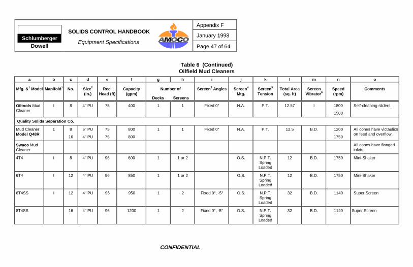
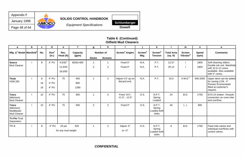
Table 6 Oilfield Mud Cleaners
a b c d e f g h i j k l m n o
Mfg. & 1 Model Manifold 1 No. Size2
(in.)Rec.
Head (ft)Capacity
(gpm)Number of
Decks Screens
Screen 3 Angles Screen 4
Mtg.Screen 5
TensionTotal Area
(sq. ft)Screen
Vibrator 6Speed(rpm)
Comments
Brandt (Division of Drexel Oilfield Services, Inc.)
12 B.D. 1750 Victaulic connections oncone inlets and overflows.
Triton Linear Mud Cleaner
I 16 3"-5” 75 3"-800
4"-800
5"-1280
1 3 Adjust -1° to +5° O.S. N.P.T. Non-SpringLoaded
27.4 I., I. 1728 Triton NNF ScreeningMachine with bolt-on16-cone desilter.
NOTES:
1. R means “radial” and I means “in-line.”
2. PU means “polyurethane,” C.I. means “cast iron,” and HV means “high volume.”
3. Negative angles means the screen slopes downward from the feed end, and positive angles means upward slopes.
4. O.S. means “overslung” and U.S. means “underslung.” N.A. means not applicable.
5. N.P.T. means “nonpretensioned” and P.T. means “pretensioned.”
6. B.D. means “belt-driven” and I. means “integral,” H.M.D. means “hydraulic motor driven.”
7. Manufacturer recommends given pressures for given mud weights.
Appendix F
January 1998
Page 50 of 64
SOLIDS CONTROL HANDBOOK
Equipment Specifications Schlumberger
Dowell
CONFIDENTIAL
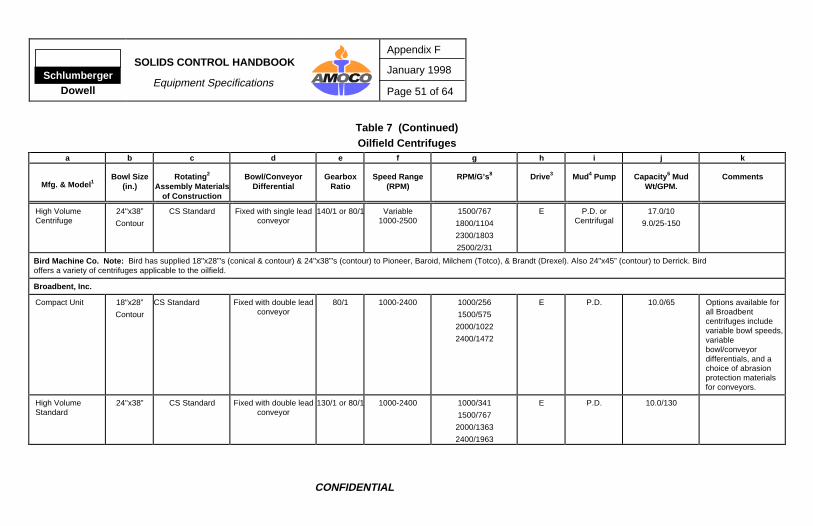
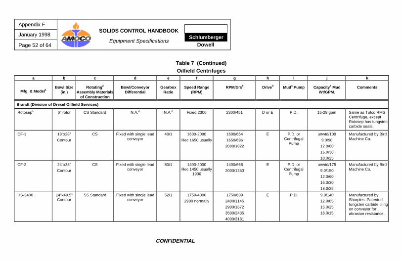
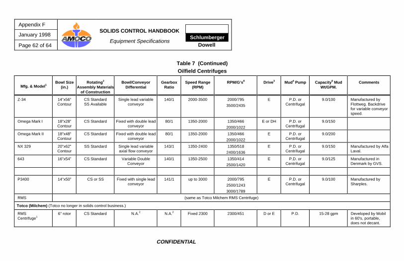
Table 7 Oilfield Centrifuges
a b c d e f g h i j k
Mfg. & Model 1Bowl Size
(in.)Rotating 2
Assembly Materialsof Construction
Bowl/ConveyorDifferential
GearboxRatio
Speed Range(RPM)
RPM/G’s8 Drive 3 Mud4 Pump Capacity 6 MudWt/GPM.
Comments
Alfa-Laval
414 14"x36”Contour
SS Adjust w/single leadconveyor
57/1 1500-3400 1500/4472500/12433400/2299
E P.D. 9.0/100
11.0/80
14.0/60
418 14"x56”Contour
SS Adjust w/single leadconveyor
57/1 1500-3400 1500/447
2500/1243
3400/2299
E P.D. 9.0/150
11.0/100
14.0/70
418 14"x56”Contour
SS Adjust w/single leadconveyor
57/1 0-4000 2000/795
3000/1790
4000/3182
E P.D. 9.0/150
11.0/100
14.0/70
Baker Hughes Treatment Services (marketing Baroid line of solids equipment.)
Standard MudCentrifuge
18"x28”Conical
CS Standard Fixed with double leadconveyor
80/1 1300-1800 1300/432
1800/828
DH, EH P.D. 9.0/45
12-14/20
14-16/15
>16/10
SchlumbergerDowell
SOLIDS CONTROL HANDBOOK
Equipment Specifications
Appendix F
January 1998
Page 51 of 64
CONFIDENTIAL
Table 7 (Continued)Oilfield Centrifuges
a b c d e f g h i j k
Mfg. & Model 1Bowl Size
(in.)Rotating 2
Assembly Materialsof Construction
Bowl/ConveyorDifferential
GearboxRatio
Speed Range(RPM)
RPM/G’s8 Drive 3 Mud4 Pump Capacity 6 MudWt/GPM.
Comments
High VolumeCentrifuge
24"x38”
Contour
CS Standard Fixed with single leadconveyor
140/1 or 80/1 Variable1000-2500
1500/767
1800/1104
2300/1803
2500/2/31
E P.D. orCentrifugal
17.0/10
9.0/25-150
Bird Machine Co. Note: Bird has supplied 18"x28”'s (conical & contour) & 24"x38”'s (contour) to Pioneer, Baroid, Milchem (Totco), & Brandt (Drexel). Also 24"x45” (contour) to Derrick. Bird offers a variety of centrifuges applicable to the oilfield.
Broadbent, Inc.
Compact Unit 18"x28”
Contour
CS Standard Fixed with double leadconveyor
80/1 1000-2400 1000/256
1500/575
2000/1022
2400/1472
E P.D. 10.0/65 Options available forall Broadbentcentrifuges includevariable bowl speeds,variablebowl/conveyordifferentials, and achoice of abrasionprotection materialsfor conveyors.
High VolumeStandard
24"x38” CS Standard Fixed with double leadconveyor
130/1 or 80/1 1000-2400 1000/341
1500/767
2000/1363
2400/1963
E P.D. 10.0/130
Appendix F
January 1998
Page 52 of 64
SOLIDS CONTROL HANDBOOK
Equipment Specifications Schlumberger
Dowell
CONFIDENTIAL
Table 7 (Continued)Oilfield Centrifuges
a b c d e f g h i j k
Mfg. & Model 1Bowl Size
(in.)Rotating 2
Assembly Materialsof Construction
Bowl/ConveyorDifferential
GearboxRatio
Speed Range(RPM)
RPM/G’s8 Drive 3 Mud4 Pump Capacity 6 MudWt/GPM.
Comments
Brandt (Division of Drexel Oilfield Services)
Rotosep1 6" rotor CS Standard N.A.2 N.A.2 Fixed 2300 2300/451 D or E P.D. 15-28 gpm Same as Totco RMSCentrifuge, exceptRotosep has tungstencarbide seals.
22"x54” CS Standard Fixed with double leadconveyor
130/1 or80/1
1000-3200 1000/312
1500/703
2000/1250
2500/1953
3200/3199
E P.D. 10.0/230
14.0/90
Derrick Equipment Co.
DS1(Sharples 3400)
14"x49”
Contour
SS Fixed with single leadconveyor
52/1 1800-3250 1800/644
2500/1243
3250/2100
E P.D. orCentrifugal
9.0/150
17.0/20
Carbide tiles onconveyor.
DE 1000 14"49”
Contour
SS Fixed with single leadconveyor
52/1 or125/1
1800-3250 1800/644
2500/1243
3250/2100
E P.D. orCentrifugal
9.0/150
17.0/20
Carbide tiles on entirelength of conveyor.
DB1 (Bird) 24"x45”
Contour
SS Fixed with single leadconveyor
80/1 1500-2400
1600 usually
1500/767
2000/1363
2400/1963
E P.D. orCentrifugal
9.0/230
DB2 (Bird, Bird-Broadbent,Broadbent)
24"x38”
Contour
CS & SS Fixed with double leadconveyor
80/1 or130/1
1500-2400 1500/767
2000/1363
2400/1963
E P.D. orCentrifugal
9.0/150
DB3 (Bird) 18"x28”
Contour
CS Fixed with double leadconveyor
80/1 1600-2000 1600/654
2000/1022
E P.D. orCentrifugal
9.0/80
17.0/10
Appendix F
January 1998
Page 54 of 64
SOLIDS CONTROL HANDBOOK
Equipment Specifications Schlumberger
Dowell
CONFIDENTIAL
Table 7 (Continued)Oilfield Centrifuges
Mfg. & Model 1Bowl Size
(in.)Rotating 2
Assembly Materialsof Construction
Bowl/ConveyorDifferential
GearboxRatio
Speed Range(RPM)
RPM/G’s8 Drive 3 Mud4 Pump Capacity 6 MudWt/GPM.
Comments
DS2(Sharples 3000)
14"x30”
Contour
SS Fixed with single leadconveyor
52/1 2000-3250 2000/795
2500/1243
3250/2100
E P.D. orCentrifugal
9.0/120
17.0/30
Carbide tiles onconveyor.
DDO(Dorr Oliver)
16"x49”
Contour
SS Adjust 10-150 RPM 35/1 1800-4000 1800/736
3000/2045
4000/3635
E P.D. orCentrifugal
9.0/100
DFE/Solids Control (DFE purchased Bariod's line of solids control equipment; DFE sold to Reserve Pits, Inc. who sold to Baker Hughes Treatment Services; see Baker Hughes Treatment Services/Bird Machine Co.)
Flo-Trend
Model ? (same as Hutchison-Hayes Model 1430)
Model ? (same as Hutchison-Hayes Model 1448)
Geolograph-Pioneer (Merged with Swaco; now Swaco Geolograph.)
DecantmasterStandard
18"x28”
Conical
CS Standard Fixed with double leadconveyor
80/1 1500-2000 1500/575
2000/1022
DH, EH,or E
P.D. 9.0/10-50
10.0/35.0
17.0/10.1
Pioneer Centrifugeswere manufacturedby Pioneer. Patentedconveyor gaugingsystem for all units.
DecantmasterMark I
18"x28”
Contour
CS Standard Fixed with double leadconveyor
80/1 1500-2000 1500/575
2000/1022
DH, EH,or E
P.D. 9.0/20-150
10.0/70.0
17.0/20.2
Backdrive withvariable scroll speedavailable for all units.
SchlumbergerDowell
SOLIDS CONTROL HANDBOOK
Equipment Specifications
Appendix F
January 1998
Page 55 of 64
CONFIDENTIAL
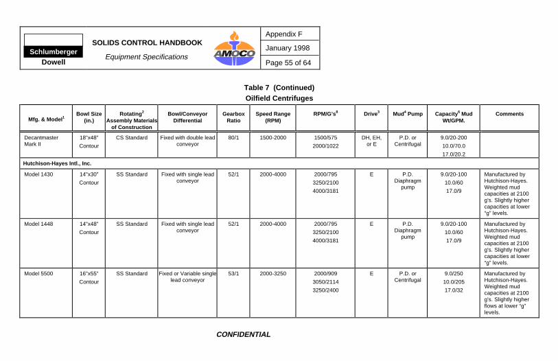
Table 7 (Continued)Oilfield Centrifuges
Mfg. & Model 1Bowl Size
(in.)Rotating 2
Assembly Materialsof Construction
Bowl/ConveyorDifferential
GearboxRatio
Speed Range(RPM)
RPM/G’s8 Drive 3 Mud4 Pump Capacity 6 MudWt/GPM.
Comments
DecantmasterMark II
18"x48”
Contour
CS Standard Fixed with double leadconveyor
80/1 1500-2000 1500/575
2000/1022
DH, EH,or E
P.D. orCentrifugal
9.0/20-200
10.0/70.0
17.0/20.2
Hutchison-Hayes Intl., Inc.
Model 1430 14"x30”
Contour
SS Standard Fixed with single leadconveyor
52/1 2000-4000 2000/795
3250/2100
4000/3181
E P.D.Diaphragm
pump
9.0/20-100
10.0/60
17.0/9
Manufactured byHutchison-Hayes.Weighted mudcapacities at 2100g's. Slightly highercapacities at lower“g” levels.
Model 1448 14"x48”
Contour
SS Standard Fixed with single leadconveyor
52/1 2000-4000 2000/795
3250/2100
4000/3181
E P.D.Diaphragm
pump
9.0/20-100
10.0/60
17.0/9
Manufactured byHutchison-Hayes.Weighted mudcapacities at 2100g's. Slightly highercapacities at lower“g” levels.
Model 5500 16"x55”
Contour
SS Standard Fixed or Variable singlelead conveyor
53/1 2000-3250 2000/909
3050/2114
3250/2400
E P.D. orCentrifugal
9.0/250
10.0/205
17.0/32
Manufactured byHutchison-Hayes.Weighted mudcapacities at 2100g's. Slightly higherflows at lower “g”levels.
Appendix F
January 1998
Page 56 of 64
SOLIDS CONTROL HANDBOOK
Equipment Specifications Schlumberger
Dowell
CONFIDENTIAL
Table 7 (Continued)Oilfield Centrifuges
Mfg. & Model 1Bowl Size
(in.)Rotating 2
Assembly Materialsof Construction
Bowl/ConveyorDifferential
GearboxRatio
Speed Range(RPM)
RPM/G’s8 Drive 3 Mud4 Pump Capacity 6 MudWt/GPM.
Comments
Hytech Centrifuges, Inc.
Hysep MD 43(previously 142)
16"x50”Contour
CS & SS Adjust 1-70 RPM 40/1 Max 28001500 or 2000 on
some units
1500/575
2000/1022
2780/1975
E, H P.D. 9.0/100
12.0/50
15.0/35
18.0/20
Manufactured by M &J in Denmark.Conveyor can runapprox. 30 RPMfaster than bowl, ifdesired. Patenteddual conveyor design.
Hysep MD53(previously 152)
20"x69”Contour
CS & SS Adjust 1-40 RPM 40/1 Max 2400 2400/1636 E, H P.D. 9.0/160
10.0/125
12.0/65
15.0/45
18.0/30
Manufactured by M &J in Denmark.Conveyor can runapprox. 30 RPMfaster than bowl, ifdesired. Patenteddual conveyor design.
Hysep MD 44 16"x64” SS & Duplex Adjust 1-40 RPM 40/1 Max 3600 3600/2945 E, H P.D. 9.0/135
10.0/95
12.0/75
18.0/35
Manufactured by M &J in Denmark. New4:1 single scroll withunique accelerationfeed chamber.
Hysep MD 54 20"x80” CS & SS Adjust 1-40 RPM 40/1 Max 2400 2400/1636 E, H P.D. 9.0/200
10.0/165
12.0/105
18.0/45
Manufactured by M &J in Denmark. New4:1 single scroll withunique accelerationfeed chamber.
SchlumbergerDowell
SOLIDS CONTROL HANDBOOK
Equipment Specifications
Appendix F
January 1998
Page 57 of 64
CONFIDENTIAL
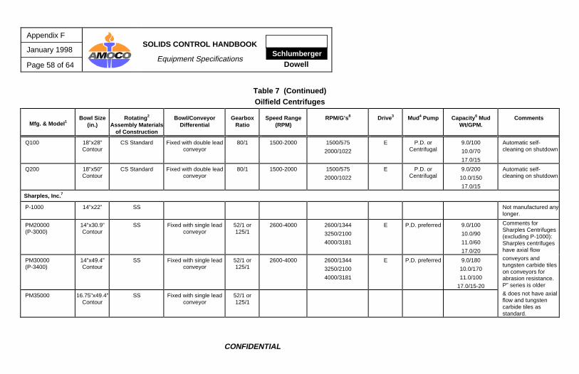
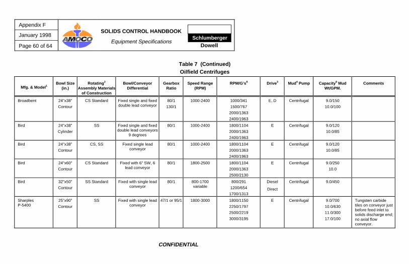
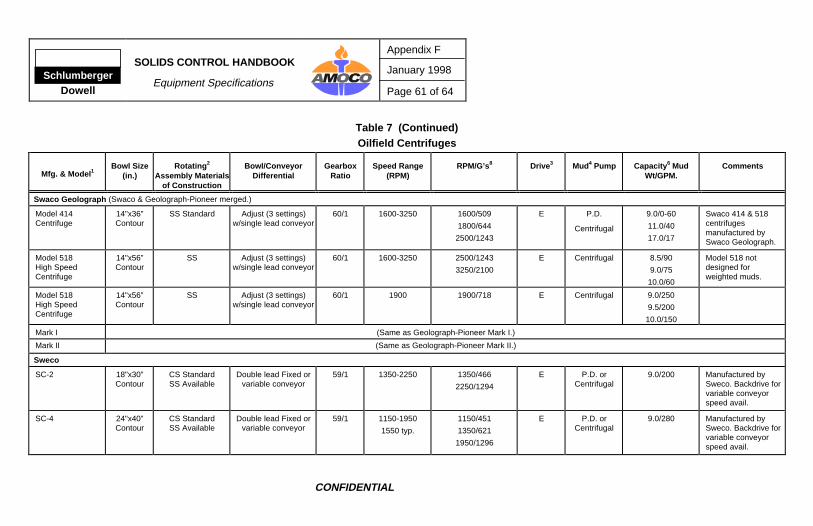
Table 7 (Continued)Oilfield Centrifuges
Mfg. & Model 1Bowl Size
(in.)Rotating 2
Assembly Materialsof Construction
Bowl/ConveyorDifferential
GearboxRatio
Speed Range(RPM)
RPM/G’s8 Drive 3 Mud4 Pump Capacity 6 MudWt/GPM.
Comments
NL Bariod (Bariod sold its line of solids control equipment to DFE/Solids Control who sold to Baker Hughes Treatment Services; see Baker Hughes Treatment Services.)
Oiltools (No longer in solids control business in USA.)
S2-1G 18"x54”Contour,Counter-
Current orCo-Current
CS Standard/SS Hydraulically variablewith single lead
conveyor
HydraulicallyVariable
0-60
0-3400 E P.D. up to 70 gpm S2-1G manufacturedby Humboldt. WATERDILUTION MUSTNOT BE USED WITHCO-CURRENTMODEL. Co-Currentmodel notrecommended forweighted muds.
S3-0G 20"x60”Contour,Counter-
Current orCo-Current
CS Standard/SS Hydraulically variablewith single lead
conveyor
HydraulicallyVariable
0-60
0-2600 E P.D. up to 97 gpm S3-0G manufacturedby Humboldt. WATERDILUTION MUSTNOT BE USED WITHCO-CURRENTMODEL. Co-Currentmodel notrecommended forweighted muds.
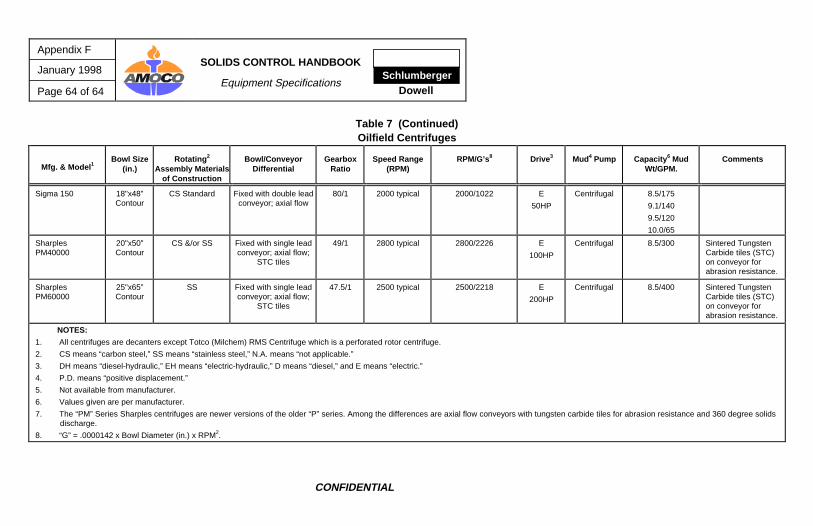
1. All centrifuges are decanters except Totco (Milchem) RMS Centrifuge which is a perforated rotor centrifuge.
2. CS means “carbon steel,” SS means “stainless steel,” N.A. means “not applicable.”
3. DH means “diesel-hydraulic,” EH means “electric-hydraulic,” D means “diesel,” and E means “electric.”
4. P.D. means “positive displacement.”
5. Not available from manufacturer.
6. Values given are per manufacturer.
7. The “PM” Series Sharples centrifuges are newer versions of the older “P” series. Among the differences are axial flow conveyors with tungsten carbide tiles for abrasion resistance and 360 degree solids discharge.