Need additional assistance? Call the Lutron Technical Support Center 1-800-523-9466. Please provide exact model number when calling. 1 For Your Information ... Wiring Lutron Occupant Sensors to Lutron Control Systems and Hardware APPLICATION NOTE #137 Quick Reference Guide Lutron Control System Notes: EcoSystemTM N 1 Y Use Ecosystem Ballast/C5-BMF Digital microWATTTM N 1-3 Y Use lighting zone controller; at least one must be connected before expansion MicroWATT® N 1-3 Y Use lighting zone controller; at least one must be connected before expansion RadioTouchTM N 1 Y Use with RTA-RX controller/RTA-SCI SoftswitchTM N* 1 Y Use with seeTouchTM wallstation/OMX-AV/Panel CCI LCP128TM N* 1 Y Use with seeTouch wallstation/OMX-AV/Panel CCI GRAFIK 5000/6000/7000TM N* 1 Y Use with seeTouch wallstation/OMX-AV GRAFIK Eye® 3000/4000 Y 0 Y Use with GRX-AV HomeWorks® Y 0 Y Use with CCI RadioRA® Y 0 Y Use with RA-SCI OMX-AV Y 0 Y Power pack must power occupant sensor** GRX-AV Y 0 Y Power pack must power occupant sensor** Panel Contact Closure Interface Y 0 Y Power pack must power occupant sensor** seeTouchTM wallstation N 1 Y Power pack used to expand system** Contact Closure Interface Y 0 Y Power pack must power occupant sensor** Power Pack Required? Number of sensors powered by system System expandable with power pack? *Power Pack required for OMX-AV and Panel CCI controls **Power Packs are able to support a MAX of three occupant sensors each Supporting Hardware Wire Size Note: Use a minimum wire size of #18 AWG (1.0 mm 2 ) for long wire runs (>2000 ft/610 m), #24 AWG (0.5 mm 2 ) for medium wire runs (500 ft/152 m to 2000 ft/610 m), and #28 AWG (0.5 mm 2 ) for short wire runs only (<500 ft/152 m). • See individual product specifications for a complete wiring guide of Lutron occupant sensors to other Lutron Lighting Control Systems ®
Transcript
Need additional assistance? Call the Lutron Technical Support Center 1-800-523-9466.Please provide exact model number when calling.
1
For Your Information ...Wiring Lutron Occupant Sensors to Lutron Control Systems and Hardware
APPLICATIONNOTE
#137Quick Reference Guide
Lutron Control System Notes:
EcoSystemTM N 1 Y Use Ecosystem Ballast/C5-BMF
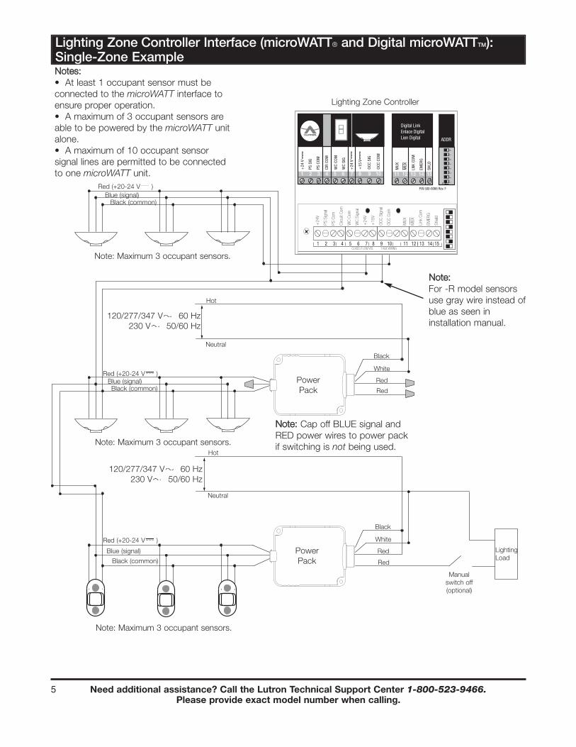
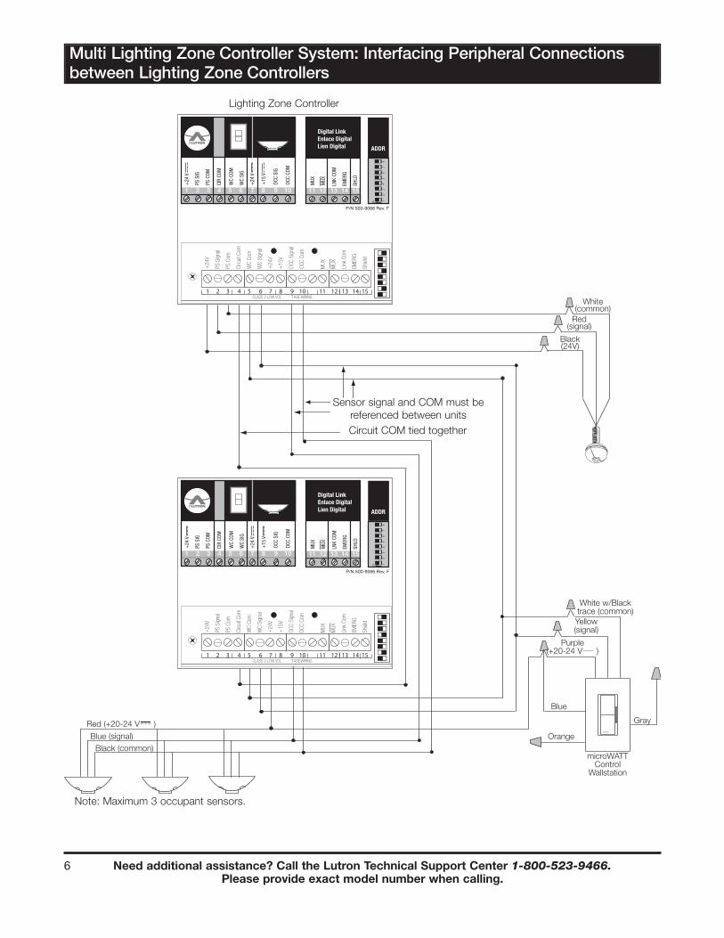
Digital microWATTTM N 1-3 YUse lighting zone controller; at least one must be
connected before expansion
MicroWATT® N 1-3 YUse lighting zone controller; at least one must be
connected before expansion
RadioTouchTM N 1 Y Use with RTA-RX controller/RTA-SCI
SoftswitchTM N* 1 Y Use with seeTouchTM wallstation/OMX-AV/Panel CCI
LCP128TM N* 1 Y Use with seeTouch wallstation/OMX-AV/Panel CCI
GRAFIK 5000/6000/7000TM N* 1 Y Use with seeTouch wallstation/OMX-AV
GRAFIK Eye® 3000/4000 Y 0 Y Use with GRX-AV
HomeWorks® Y 0 Y Use with CCI
RadioRA® Y 0 Y Use with RA-SCI
OMX-AV Y 0 Y Power pack must power occupant sensor**
GRX-AV Y 0 Y Power pack must power occupant sensor**
Panel Contact Closure Interface Y 0 Y Power pack must power occupant sensor**
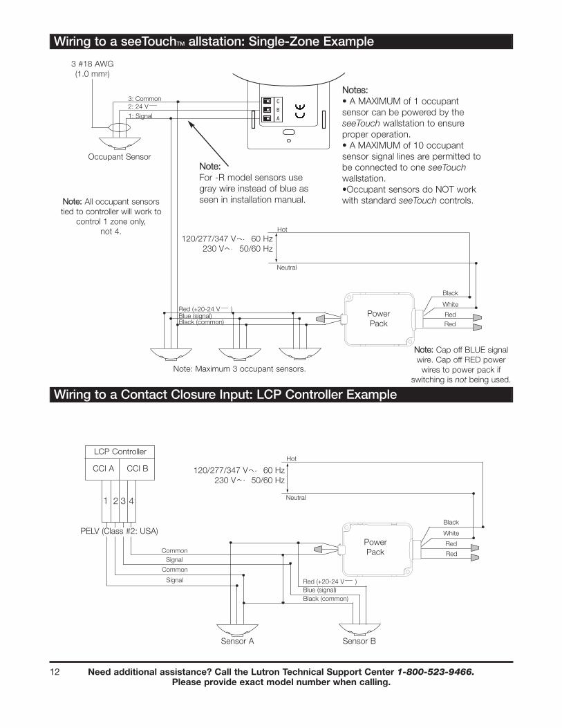
seeTouchTM wallstation N 1 Y Power pack used to expand system**
Contact Closure Interface Y 0 Y Power pack must power occupant sensor**
Pow
er
Pack R
eq
uired
?
Num
ber
of
sensors
pow
ere
d b
y s
yste
m
Syste
m e
xp
and
ab
le
with p
ow
er
pack?
*Power Pack required for OMX-AV and Panel CCI controls
**Power Packs are able to support a MAX of three occupant sensors each
SSuuppppoorrttiinngg HHaarrddwwaarree
WWiirree SSiizzee NNoottee::Use a minimum wire size of #18 AWG (1.0 mm2) for long wire runs (>2000 ft/610 m), #24 AWG (0.5 mm2) for medium wire runs (500 ft/152 m to 2000 ft/610 m), and #28 AWG (0.5 mm2) for short wire runs only (<500 ft/152 m).
• See individual product specifications for a complete wiring guide of Lutron occupant sensors to other Lutron
Refer to the Installers Guide for more detailed instructions.Consulte la Guía de Instaladores para información más detallada.Référer au Guide d’installation pour plus de renseignements détaillés.
120/277 V 60 Hz16 A Max.
0-10 V
LOS-CDT-x000R-WH
Yellow/White (NO)
Black/White (NC)
Blue/White (common)
Gray Blue
RTA-RX-F-SC
NNoottee:: Maximum of 3 sensors can be powered
by the unit.
Black (common)
Red (+20-24 V )
Black (common)
Red (+20-24 V )
Need additional assistance? Call the Lutron Technical Support Center 1-800-523-9466.Please provide exact model number when calling.
4
Combined Emergency and Occupant Sensor Function with RadioTouchTM
CAUTION! This equipment has more than one power connection point. To reduce the risk of electrical shock disconnect both the branch circuit breakers or fuses before ser vicing.
CAUTION! Read instruction manual for installation, operation, and maintenance instructions.
For use with Lutron GRAFIK Eye ®
GP-, XP-, LP- Series panels and RadioTouchTM Controllers
Refer to the Installers Guide for more detailed instructions.Consulte la Guía de Instaladores para información más detallada.Référer au Guide d’installation pour plus de renseignements détaillés.
120/277 V 60 Hz16 A Max.
0-10 V
LOS-CDT-x000R-WH
Yellow/White (NO)
Black/White (NC)
Blue/White (common)
Gray Blue
RTA-RX-F-SC LUT-ELI-3PH
OFF during non-occupancy
ON during occupancy
24 V
Common
Signal
Need additional assistance? Call the Lutron Technical Support Center 1-800-523-9466.Please provide exact model number when calling.
5
Lighting Zone Controller Interface (microWATT® and Digital microWATTTM):Single-Zone Example