1 Application Architecture and Modeling Based on Chapter 13 of Whitten, Bentley, and Dittman: Systems Analysis and Design for the Global Enterprise (7th Ed). McGraw Hill. 2007 Wei-Tsong Wang IIM, NCKU 2 Application Architecture Application architecture – a specification of the technologies to be used to implement information systems. The blueprint to communicate the following design decisions: The degree to which the information system will be centralized or distributed. The distribution of stored data. The implementation technology for software developed in-house. The integration of commercial off-the-shelf software. The technology to be used to implement the user interface. The technology to be used to interface with other systems
Transcript
1
Application Architectureand Modeling
Based on Chapter 13 of Whitten, Bentley, andDittman:Systems Analysis and Design for the GlobalEnterprise (7th Ed). McGraw Hill. 2007
Wei-Tsong WangIIM, NCKU
2
Application Architecture
Application architecture –a specification of thetechnologies to be used to implement informationsystems.The blueprint to communicate the following designdecisions: The degree to which the information system will be
centralized or distributed. The distribution of stored data. The implementation technology for software
developed in-house. The integration of commercial off-the-shelf software. The technology to be used to implement the user
interface. The technology to be used to interface with other
systems
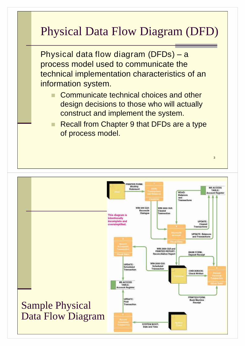
3
Physical Data Flow Diagram (DFD)
Physical data flow diagram (DFDs) –aprocess model used to communicate thetechnical implementation characteristics of aninformation system.
Communicate technical choices and otherdesign decisions to those who will actuallyconstruct and implement the system.
Recall from Chapter 9 that DFDs are a typeof process model.
4
Sample PhysicalData Flow Diagram
5
Physical Processes
Physical process –either a processor, such as a computer orperson, or a technical implementation of specific work to beperformed, such as a computer program or manual process.
Logical processes may be assigned to physical processorssuch as PCs, servers, people, or devices in a network. Aphysical DFD would model that network structure.
Each logical process requires an implementation as one ormore physical processes.A logical process may be split into multiple physicalprocesses for one or more of the following reasons: To define aspects performed by people or computers. To define aspects implemented by different technologies. To show multiple implementations of the same process. To add processes for exceptions and security.
6
Physical Process Notation
ID (optional)
Action Verb+
Noun or ObjectPhrase
Implementation
7
Samples of Physical Processes
8
Possible Computer ProcessImplementationsA purchased application software package
Also called commercial off-the-shelf (COTS)software
A system or utility programSuch as an e-mail/message server or third-party
frameworkAn existing application program from a
program libraryMay require modification
A program to be written
9
Sample Physical ProcessImplementations
10
Physical Data Flows
A physical data flow represents any of thefollowing:Planned implementation of an input to, or output from
a physical process.Database command or action such as create, read,
update, or delete. Import of data from, or
export of data to anotherinformation system.
Flow of data betweentwo modules orsubroutines (representedas physical processes).
Implementation method:Data flow name
Data flow name(Implementation method)
OR
11
Sample Physical Data Flows
12
Sample Physical Data Flows(continued)
13
Physical External Agents
Physical external agents are carried overfrom the logical DFD models.If scope changes, the logical models
should be changed before the physicalmodels are drawn.
14
Physical Data Stores
A physical data store represents the plannedimplementation of one of:
A databaseA table in a databaseA computer fileA tape or media backup of anything importantA temporary file or batchAny type of noncomputerized file
15
Physical Data Store Notation
16
Physical Data Store Implementations
17
Information Technology (IT)Architecture
Information Technology (IT)Architecture addresses “real”technologies to be used for constructinginformation systems.Systems ArchitectureData ArchitectureInterface ArchitectureProcess Architecture
18
Distributed versus CentralizedSystems
Distributed system –a system in whichcomponents are distributed across multiplelocations and computer networks.
Accordingly, the processing workload is distributedacross multiple computers on the network.
Centralized systems –a system in which allcomponents are hosted by a central, multi-usercomputer.
Users interact with the system via terminals (or aPC emulating a terminal).
Virtually all the actual processing and work is doneon the host computer.
19
Computing Layers
Presentation layer—the user interface
Presentation logic layer—processing that must bedone to generate the presentation, such as editinginput data or formatting output data.
Application logic layer—the logic and processing tosupport business rules, policies, and procedures
Data manipulation layer—to store and retrieve datato and from the database
Data layer—the actual business data
20
Types ofDistributedComputing
21
Distributes Systems Architecture
There are 3 basic types of distributessystems architecture:File Server ArchitectureClient/Server ArchitectureInternet-Based Architecture
22
Data Architectures
Relational database stores data in tabular form. Eachfile is implemented as a table. Each field is a column inthe table. Related records between two tables areimplemented by intentionally duplicated columns in thetwo tables.
Distributed relational database –A database systemthat duplicates tables to multiple database serverslocated in geographically important locations.
Distributed relational database managementsystem –a software program that controls access toand maintenance of stored data in the relational format.
23
Types of Data(base) Distribution
Data partitioning truly distributes rows and columnsof tables to specific database servers with little or noduplication between servers.
Vertical partitioning assigns different columns todifferent servers.
Horizontal partitioning assigns different rows todifferent servers.
Data replication duplicates some or all tables onmore than one database server.
Propagates updates on one database server to anyother database server where the data is duplicated.
24
Data Partitioning versusData Replication
25
Interface Architectures –Inputs,Outputs, & MiddlewareBatch inputs and outputsOnline inputs and outputsRemote batchKeyless data entry (and automatic identification)Pen inputElectronic messaging and work group technologyElectronic Data Interchange (EDI) Imaging and document interchangeMiddleware
26
Electronic Data Interchange (EDI)
Electronic Data Interchange (EDI) –thestandardized electronic flow of businesstransactions or data between businesses.
Typically, many businesses must agree to acommon data format to make EDI feasible.
27
Middleware
Middleware –utility software that enablescommunication between different processors ina system.
It may be built into the respective operatingsystems or added through purchasedmiddleware products.
A process architecture is defined in terms of thesoftware languages and tools that will be used todevelop the business logic and applicationprograms for that process.
29
Process Architectures (Cont.)
Software development environment (SDE) –a languageand tool kit for developing applications.
SDEs exist for centralized computingSDEs exist for distributed presentationSDEs exist for two-tiered client/serverSDEs exist for multi-tiered client/serverSDEs exist for Internet and intranet client/server
Clean layering –a design strategy that requires thatpresentation, application, and data layers of an applicationbe physically separated.
Allows components of each layer to be revised orenhanced without affecting the other layers.
30
Application Architecture Strategiesfor System Design
The Enterprise Application Architecture StrategyEnterprise-wide information technology architecture
to be followed in all development projects. Approved network, data, interface, and processing
technologies and development tools. Strategy for integrating legacy systems and
technologies. On-going process for continuously reviewing
application architecture. On-going process for researching emerging
technologies Process for analyzing requests for variances from
the above.
31
Application Architecture Strategiesfor System Design (Cont.)
The Tactical Application ArchitectureStrategyDefines architecture for each new system
on an application-by-application basis asneeded.
Requires feasibility analysis for eachapplication.
32
Modeling the Application Architectureof an Information System
3 suggested tasks:Drawing Physical DFDs for Network
ArchitectureDrawing Data Distribution and Technology
Assignments DFDDrawing Process Distribution and
Technology Assignments
33
Drawing Physical DFDs forNetwork Architecture
Develop a physical data flow diagram (DFD)for the network architecture.Each process symbol represents a server or class
of clients.
For each processor, develop a physical DFDto show the event processes (from Chapter 9)that are assigned to that processor.
All but simple processes should be factoredinto design units and modeled as a moredetailed physical DFDs.
34
Design Units
Design unit –a self-contained collection ofprocesses, data stores, and data flows thatshare similar design characteristics.
A design unit serves as a subset of the totalsystem whose inputs, outputs, files anddatabases, and programs can be designed,constructed, and tested as a self-containedunit.
Ultimately, design units must be integratedinto a whole system.
35
The Network Architecture DFD
Network architecture –a physical DFD thatallocates processors (clients and servers) anddevices (machines and robots) to a networkand establishes:
the connectivity between clients and serverswhere users will interface with the processors
36
Network Architecture DFD
37
Data Distribution Options
Store all data on a single server.Store specific tables on different servers.Store subsets of specific tables on different
servers.Replicate (duplicate) specific tables or
subsets on different servers.
38
Data Distribution and TechnologyAssignments DFD
39
Process Distribution andTechnology Assignments For two-tiered client/server systems, all logical even
diagrams are assigned to the client. For three-tiered client/server and network computing
systems, must closely examine each event’s primitive(detailed) DFD.Determine which primitive processes should be
assigned to the client and which should be assignedto an application server.
Generally data capture and editing are assigned toservers
If different aspects of a single DFD are partitioned todifferent clients and servers, draw separate physicalDFD for each.
40
Physical DFDfor an Event
See Figure 13-13in text for a morereadable version
41
ThePerson/MachineBoundary
See Figure 13-14in text for a morereadable version