44
https://support.industry.siemens.com/cs/ww/en/view/29430270 Application Description 01/2016 Configuration Control with the S7-1500 and ET 200SP S7-1500, ET 200SP
| Date post: | 22-Aug-2018 |
| Category: |
Documents |
| Upload: | nguyendung |
| View: | 231 times |
| Download: | 0 times |

https://support.industry.siemens.com/cs/ww/en/view/29430270
Application Description 01/2016
Configuration Control with the S7-1500 and ET 200SP S7-1500, ET 200SP
Warranty and Liability
OH_S71500 Entry ID: 29430270, V2.0, 01/2016 2
S
iem
en
s A
G 2
01
6 A
ll ri
gh
ts r
ese
rve
d
Warranty and Liability
Note The Application Examples are not binding and do not claim to be complete with regard to configuration, equipment or any contingencies. The Application Examples do not represent customer-specific solutions. They are only intended to provide support for typical applications. You are responsible for the correct operation of the described products. These Application Examples do not relieve you of the responsibility of safely and professionally using, installing, operating and servicing equipment. When using these Application Examples, you recognize that we cannot be made liable for any damage/claims beyond the liability clause described. We reserve the right to make changes to these Application Examples at any time and without prior notice. If there are any deviations between the recommendations provided in this Application Example and other Siemens publications – e.g. Catalogs – the contents of the other documents shall have priority.
We do not accept any liability for the information contained in this document.
Any claims against us – based on whatever legal reason – resulting from the use of the examples, information, programs, engineering and performance data etc., described in this Application Example shall be excluded. Such an exclusion shall not apply in the case of mandatory liability, e.g. under the German Product Liability Act (“Produkthaftungsgesetz”), in case of intent, gross negligence, or injury of life, body or health, guarantee for the quality of a product, fraudulent concealment of a deficiency or breach of fundamental contractual obligations (“wesentliche Vertragspflichten”). The compensation for damages due to a breach of a fundamental contractual obligation is, however, limited to the foreseeable damage, typical for the type of contract, except in the event of intent or gross negligence or injury to life, body or health. The above provisions do not imply a change of the burden of proof to your detriment.
Any form of duplication or distribution of these Application Examples or excerpts hereof is prohibited without the expressed consent of Siemens AG.
Security informa-
tion
Siemens provides products and solutions with industrial security functions that support the secure operation of plants, solutions, machines, equipment and/or networks. They are important components in a holistic industrial security concept. With this in mind, Siemens products and solutions undergo continuous development. Siemens recommends strongly that you regularly check for product updates.
For the secure operation of Siemens products and solutions, it is necessary to take suitable preventive action (e.g. cell protection concept) and integrate each component into a holistic, state-of-the-art industrial security concept. Third-party products that may be in use should also be considered. For more information about industrial security, visit http://www.siemens.com/industrialsecurity.
To stay informed about product updates as they occur, sign up for a product-specific newsletter. For more information, visit http://support.industry.siemens.com.

Table of Contents
OH_S71500 Entry ID: 29430270, V2.0, 01/2016 3
S
iem
en
s A
G 2
01
6 A
ll ri
gh
ts r
ese
rve
d
Table of Contents Warranty and Liability ................................................................................................. 2
1 Task ..................................................................................................................... 4
2 Solution............................................................................................................... 8
2.1 Principle ................................................................................................ 8 2.1.1 Presentation of the solution .................................................................. 8 2.1.2 Real hardware configuration of the production plant ........................... 9 2.1.3 Configured hardware configuration of the STEP 7 project ................. 10 2.2 Description of the core functionality ................................................... 11 2.3 Hardware and software components ................................................. 14 2.3.1 Validity ................................................................................................ 14 2.3.2 Components used .............................................................................. 14
3 Configuration Control Basics ......................................................................... 15
3.1 What is configuration control? ............................................................ 15 3.1.1 Description ......................................................................................... 15 3.1.2 Applicable methods ............................................................................ 15 3.2 Function principle ............................................................................... 17 3.2.1 Enabling configuration control ............................................................ 17 3.2.2 Reconfiguration via the control data record ....................................... 18 3.2.3 Characteristics .................................................................................... 20 3.3 Diagnostics using function blocks ...................................................... 21
4 Principle of Operation and Parameterization ............................................... 24
4.1 General overview ............................................................................... 24 4.2 Program overview .............................................................................. 24 4.3 Control data records ........................................................................... 29 4.3.1 Control data record for the S7-1500 ................................................... 29 4.3.2 Control data records for the ET 200SP .............................................. 30
5 Installation and Commissioning .................................................................... 33
5.1 Installing the hardware ....................................................................... 33 5.2 Installing TIA Portal ............................................................................ 35 5.3 Commissioning ................................................................................... 35 5.3.1 IP address assignment ....................................................................... 35 5.3.2 Loading the project ............................................................................. 37
6 Operating the Application ............................................................................... 38
7 Links & Literature ............................................................................................ 44
8 History............................................................................................................... 44

1 Task
OH_S71500 Entry ID: 29430270, V2.0, 01/2016 4
S
iem
en
s A
G 2
01
6 A
ll ri
gh
ts r
ese
rve
d
1 Task
Introduction
High cost pressure associated with project planning, design, wiring and documentation leads to modularization and standardization of hardware and software for the various configurations and variants of a machine. The requirements - customized configuration of a station and flexible expansions while retaining the configuration and the control program - that seem conflicting at first glance are met by configuration control (option handling).
For modular machine concepts, for example, in series machine building, configuration control offers savings potential for the creation, commissioning and documentation.
Until now, this has only been possible on the distributed IO systems ET 200S and ET 200pro. Expanding the ET 200 portfolio and the new firmware for the S7-1200 and S7-1500 has significantly expanded the options.
In the course of this process, a library, OH_S71x00_Library, was developed for TIA Portal. The blocks included in it support you in parameterizing and implementing configuration control (central/distributed) for all usable modules.
This application shows the use of this library.

1 Task
OH_S71500 Entry ID: 29430270, V2.0, 01/2016 5
S
iem
en
s A
G 2
01
6 A
ll ri
gh
ts r
ese
rve
d
Overview of the automation task
The automation task simulates a fictitious muffin production plant. This production plant includes
a "baking unit",
a "decorating module",
a "packaging unit"
To be able to offer different types of muffins, the following variants are conceivable:
Variant 1: Muffins without decorations and without packaging.
Variant 2: Muffins without decorations and with packaging.
Variant 3: Muffins with decorations and with packaging.
Figure 1-1
Baking unit
Baking unit + decorating module
Baking unit + decorating module + packaging unit
Variant1
Variant 2
Variant 3
Description of the automation task
"Muffin production" is used for the application example.
1 Task
OH_S71500 Entry ID: 29430270, V2.0, 01/2016 6
S
iem
en
s A
G 2
01
6 A
ll ri
gh
ts r
ese
rve
d
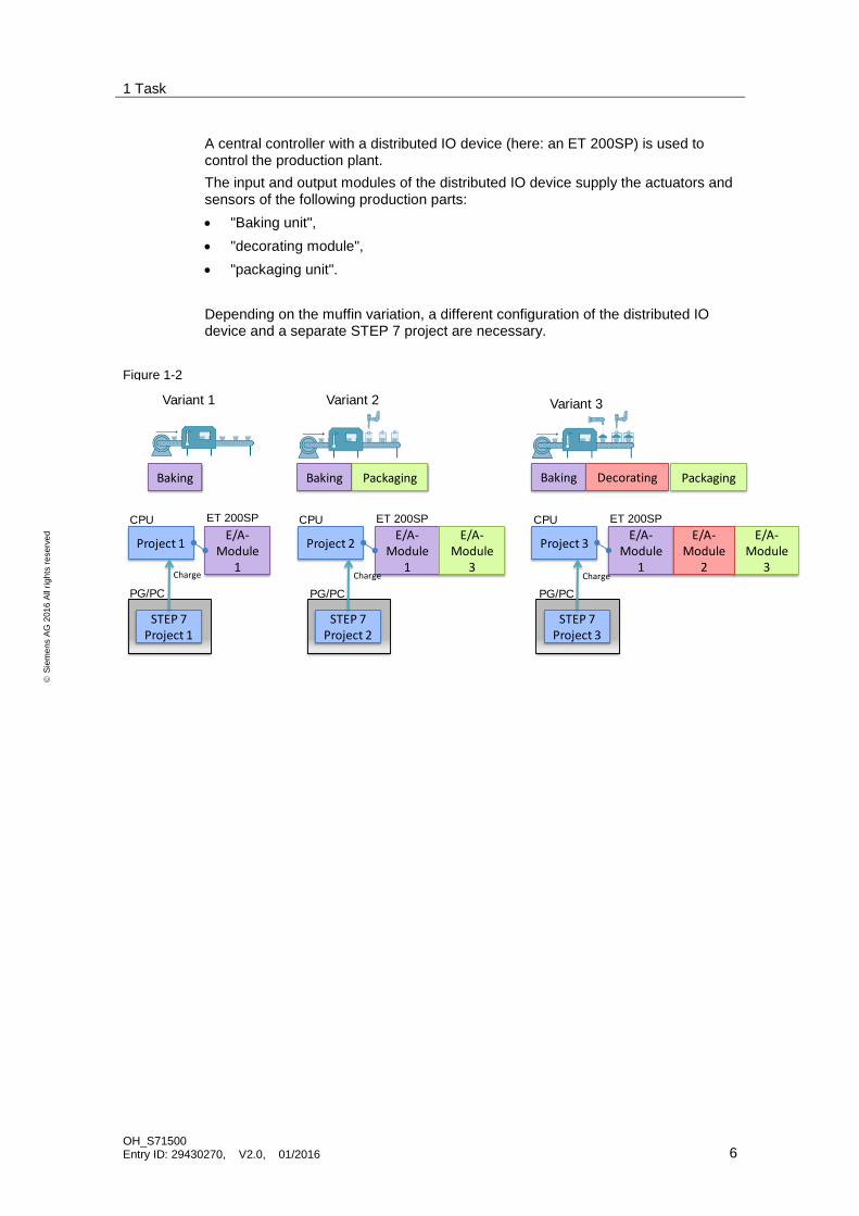
A central controller with a distributed IO device (here: an ET 200SP) is used to control the production plant.
The input and output modules of the distributed IO device supply the actuators and sensors of the following production parts:
"Baking unit",
"decorating module",
"packaging unit".
Depending on the muffin variation, a different configuration of the distributed IO device and a separate STEP 7 project are necessary.
Figure 1-2
Variant 1 Variant 2 Variant 3
Baking
E/A-Module
1
ET 200SP
Project 1
CPU
E/A-Module
1
ET 200SP
Project 2
CPU
E/A-Module
1
ET 200SP
Project 3
CPU
PackagingBaking Baking Packaging
E/A-Module
3
E/A-Module
3
Decorating
E/A-Module
2
STEP 7Project 1
PG/PC
Charge
STEP 7Project 2
STEP 7Project 3
PG/PC PG/PC
Charge Charge

1 Task
OH_S71500 Entry ID: 29430270, V2.0, 01/2016 7
S
iem
en
s A
G 2
01
6 A
ll ri
gh
ts r
ese
rve
d
Objective of the automation task
Now the task is to automate all variations with the same STEP 7 project.
The figure below illustrates the correlations.
Figure 1-3
Variant 1 Variant 2 Variant 3
Baking
E/A-Module
1
ET 200SP
Project
CPU
E/A-Module
1
ET 200SP
Project
CPU
E/A-Module
1
ET 200SP
Projekt
CPU
PackagingBaking Baking Packaging
E/A-Module
3
E/A-Module
3
Decorating
E/A-Module
2
STEP 7Project
PG/PC
Charge
In specific terms, the aim is to achieve the following objectives:
Retrofitting variants without reconfiguring the station.
Enabling IO modules by the PLC program.
Easy diagnostics of all occurring errors, regardless of the current configuration variant - without program modifications.
One STEP 7 project for all variations.

2 Solution
OH_S71500 Entry ID: 29430270, V2.0, 01/2016 8
S
iem
en
s A
G 2
01
6 A
ll ri
gh
ts r
ese
rve
d
2 Solution
2.1 Principle
2.1.1 Presentation of the solution
Description
With configuration control (option handling), SIMATIC offers a solution to the above-described task: A single STEP 7 project covers all production variants.
This is made possible by a configurable assignment of configured to physically existing station modules by means of a control data record that is transferred to the affected device if necessary.
For this purpose, configuration control uses different methods:
Configuration control for central configuration (central processing unit).
Configuration control for distributed configuration (distributed IO device).
Advantages
Easier project handling and commissioning due to the use of a single STEP 7 project for all variations.
Easier handling in terms of maintenance, versioning and upgrade.
Savings in hardware costs: Only IO modules necessary for the current variant of the machine are installed in the ET 200SP.
Topics not covered in this application
This application does not include a description of the following:
Configuring the hardware and using TIA Portal.
Programming SIMATIC S7.
Network technology and protocols.
Contents and principle of operation of the OH_S71x00_Library.
Basic knowledge of these topics is required.
In addition, this application does not focus on programming muffin production but on implementing configuration control and the parameterization and configuration steps associated with it.
Note The OH_S71x00_Library and a library description can be found on the same HTML page as this document (see \2\).
Assumed knowledge
Basic knowledge of the SIMATIC automation system and ET 200SP is required. Advanced knowledge of the TIA Portal engineering software is also necessary.

2 Solution
OH_S71500 Entry ID: 29430270, V2.0, 01/2016 9
S
iem
en
s A
G 2
01
6 A
ll ri
gh
ts r
ese
rve
d
2.1.2 Real hardware configuration of the production plant
Diagrammatic representation
The diagrammatic representation below shows the real components involved in the
solution:
Figure 2-1
PROFINET IE
S7-1500
OH_S71x00_Library
Variant 1
Control/ HMI
distributed IO systemET 200SP
„Bak
ing“
„Bak
ing“
„Pac
kagi
ng“
„Bak
ing“
„Dec
ora
tin
g“
„Pac
kagi
ng“
Variant2 Variant 3
Panel
Configuration
The production plant is automated by the following devices:
the S7-1500 central control unit
the ET 200SP distributed IO system
the TP 700 operating panel.
The control unit consists of the CPU 1516-3 central processing unit.
The ET 200SP distributed IO device is represented by the IM155-3 ST interface module and - depending on the variant - equipped with various input and output modules.
The operating panel TP 700 Comfort is used for selecting the variants.
A single STEP 7 project is created that is applicable to all muffin variants. The blocks of the OH_S71x00_Library are used for configuration control.

2 Solution
OH_S71500 Entry ID: 29430270, V2.0, 01/2016 10
S
iem
en
s A
G 2
01
6 A
ll ri
gh
ts r
ese
rve
d
2.1.3 Configured hardware configuration of the STEP 7 project
Diagrammatic representation
For comparison, the diagrammatic representation below shows the configured
hardware (the HMI panel is not presented here) in the shared STEP 7 project.
Figure 2-2
Configuration
The hardware configuration of the production plant contains the S7-1516-3PN central control unit with any number of input and output modules.
Note The IO modules of the S7-1516-3PN are not relevant to the actual muffin production. They serve only to illustrate configuration control also for central configuration.
The ET 200SP distributed IO device is configured in the maximum configuration, including all the input and output modules the muffin variations require in total.
Which input and output modules are used for the desired variant is defined during runtime via the control data record.

2 Solution
OH_S71500 Entry ID: 29430270, V2.0, 01/2016 11
S
iem
en
s A
G 2
01
6 A
ll ri
gh
ts r
ese
rve
d
2.2 Description of the core functionality
The basic idea of this application is the use of a shared STEP 7 project despite differently equipped IO modules of the distributed IO system - due to the muffin variations.
This is made possible by configuration control.
Due to configuration control, the distributed IO device or the central processing unit can be configured in the maximum configuration and still be operated with missing IO modules. If missing IO modules are retrofitted at a later time, reconfiguring and therefore reloading the hardware configuration are not required.
The basis for this is a configurable assignment of configured to physically existing station modules by means of a control data record that is transferred to the controller or interface module if necessary.
Sequence of the core functionality
The specific sequence provided by the application is as follows:
1. In the STEP 7 project, the distributed IO is configured in the maximum configuration and the controller is configured with any IO modules.
2. In a central database,
a. for all muffin variations
b. for the central control unit,
in each case with the aid of the ready-made PLC data types from the OH_S71x00_Library, a separate data structure has been created that
contains the current setpoint configuration.
3. The desired muffin variant is selected using an HMI visualization.
4. The user program is designed such that the necessary control data record is sent to the device (CPU or ET 200SP) at the right time with the aid of the function block from the OH_S71x00_Library.
2 Solution
OH_S71500 Entry ID: 29430270, V2.0, 01/2016 12
S
iem
en
s A
G 2
01
6 A
ll ri
gh
ts r
ese
rve
d
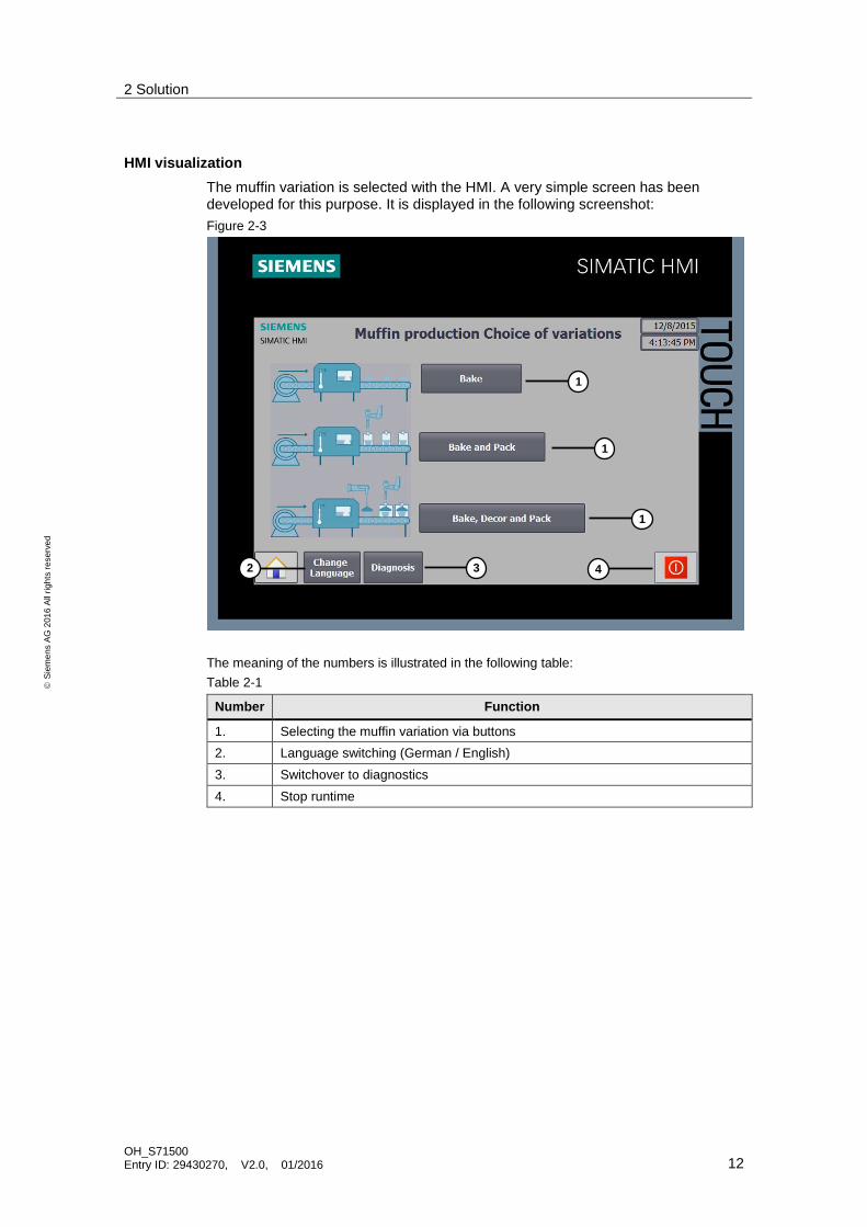
HMI visualization
The muffin variation is selected with the HMI. A very simple screen has been developed for this purpose. It is displayed in the following screenshot:
Figure 2-3
The meaning of the numbers is illustrated in the following table:
Table 2-1
Number Function
1. Selecting the muffin variation via buttons
2. Language switching (German / English)
3. Switchover to diagnostics
4. Stop runtime
1
2
1
1
4 3

2 Solution
OH_S71500 Entry ID: 29430270, V2.0, 01/2016 13
S
iem
en
s A
G 2
01
6 A
ll ri
gh
ts r
ese
rve
d
Visualization of the diagnostics information of the modules and devices in the application example is carried out via the HMI. It is displayed in the following screenshot:
Figure 2-4
Table 2-2
Number Function
1. Selecting the HW identifier of the PROFINET IO system to be diagnosed
2. Selecting the mode for the PROFINET IO system diagnostics
3. Group diagnostics for the PROFINET IO system diagnostics
4. Representation of the diagnostics information for each device in the PROFINET IO system (n=device number)
5. Selecting the HW identifier of the device to be diagnosed
6. Selecting the mode for the device diagnostics
7. Group diagnostics for the device diagnostics
8. Representation of the diagnostics information for each module of the device (Slot=n-1)
1
2
5
3 6
3
4
7
5
3
8
3

2 Solution
OH_S71500 Entry ID: 29430270, V2.0, 01/2016 14
S
iem
en
s A
G 2
01
6 A
ll ri
gh
ts r
ese
rve
d
2.3 Hardware and software components
2.3.1 Validity
This application is valid for
STEP 7 V14 Update 2 or higher
S7-1500 CPU (firmware version V1.5 or higher)
ET 200SP distributed IO device
2.3.2 Components used
The application has been created with the following components:
Hardware components
Table 2-3
Component No. Order number Note
CPU 1516-3 PN/DP 1 6ES7 516-3AN00-0AB0 Or other CPU
IM 155-6 PN ST 1 6ES7 155-6AU00-0BN0 ET 200SP interface module
DI 8x24VDC ST 1 6ES7 131-6BF00-0BA0 For the "baking unit"
DQ 4x24VDC/2A ST 1 6ES7 132-6BD20-0BA0 For the "decorating module"
DQ 8x24VDC/0.5A ST
1 6ES7 132-6BF00-0BA0 For the "packaging unit"
BU15-P16+A10+2D 1 6ES7 193-6BP20-0DA0 Type A0 BASEUNIT with new load group
BU15-P16+A10+2B 2 6ES7 193-6BP20-0BA0 Type A0 BASEUNIT
TP700 Comfort Panel 1 6AV2124-0GC01-0AX0 In this application, the panel is simulated by the HMI-Runtime.
Software components
Table 2-4
Component Order number Note
TIA Portal V14 6ES7822-1AA04-0YA5
The link to the current updates for TIA Portal can be found here: \3\.
WinCC V14 6AV210.-....4-0
Sample files and projects
The following list includes all files and projects that are used in this example.
Table 2-5
Component Note
29430270_OH_S71500_APPL_CODE_V10.zip This zip file contains the STEP 7 project.
29430270_OH_S71500_APPL_DOKU_V10_e.pdf This document.
3 Configuration Control Basics
OH_S71500 Entry ID: 29430270, V2.0, 01/2016 15
S
iem
en
s A
G 2
01
6 A
ll ri
gh
ts r
ese
rve
d
3 Configuration Control Basics
3.1 What is configuration control?
3.1.1 Description
Configuration control facilitates the automation of machines with different configurations of the distributed IO system or the central processing unit. This becomes clear when one looks at the different methods.
Without configuration control - the configuration of the station is configured in STEP 7. The real configuration of the stations on the machine must match the configured configuration. A STEP 7 project can only be used for a single real configuration.
With configuration control - the configuration of the stations is also configured in STEP 7. However, this configuration includes all the IO modules of all the variants of the machine. Different real configurations of stations can be operated with a single STEP 7 project or a single configuration (maximum configuration). A single STEP 7 project can therefore be used for multiple real configurations of
stations.
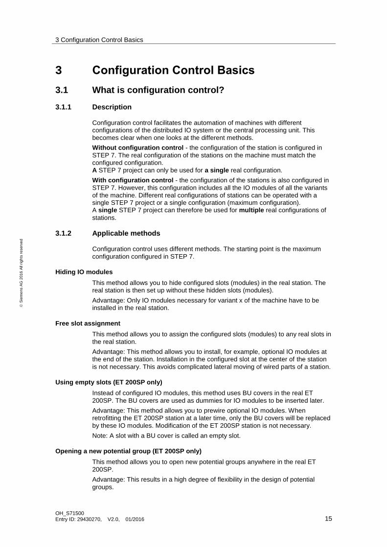
3.1.2 Applicable methods
Configuration control uses different methods. The starting point is the maximum configuration configured in STEP 7.
Hiding IO modules
This method allows you to hide configured slots (modules) in the real station. The real station is then set up without these hidden slots (modules).
Advantage: Only IO modules necessary for variant x of the machine have to be installed in the real station.
Free slot assignment
This method allows you to assign the configured slots (modules) to any real slots in the real station.
Advantage: This method allows you to install, for example, optional IO modules at the end of the station. Installation in the configured slot at the center of the station is not necessary. This avoids complicated lateral moving of wired parts of a station.
Using empty slots (ET 200SP only)
Instead of configured IO modules, this method uses BU covers in the real ET 200SP. The BU covers are used as dummies for IO modules to be inserted later.
Advantage: This method allows you to prewire optional IO modules. When retrofitting the ET 200SP station at a later time, only the BU covers will be replaced by these IO modules. Modification of the ET 200SP station is not necessary.
Note: A slot with a BU cover is called an empty slot.
Opening a new potential group (ET 200SP only)
This method allows you to open new potential groups anywhere in the real ET 200SP.
Advantage: This results in a high degree of flexibility in the design of potential groups.

3 Configuration Control Basics
OH_S71500 Entry ID: 29430270, V2.0, 01/2016 16
S
iem
en
s A
G 2
01
6 A
ll ri
gh
ts r
ese
rve
d
Combining the methods
For a station, all the above-listed methods can also be used simultaneously.
Methods used in this application
The following methods are used in this application example:
Hiding IO modules (S7-1500 and ET 200SP): All input and output modules that are not needed in the real configuration are hidden via the control data record.
Free slot assignment (ET 200SP): Muffin production of variant 2 (muffins without decorations and with packaging) does not require the decorating
module. Therefore, the packaging unit can use this slot.

3 Configuration Control Basics
OH_S71500 Entry ID: 29430270, V2.0, 01/2016 17
S
iem
en
s A
G 2
01
6 A
ll ri
gh
ts r
ese
rve
d
3.2 Function principle
To be able to use configuration control, two steps are of importance:
1. Enabling configuration control in the module.
2. Programming and writing the control data record.
3.2.1 Enabling configuration control
Reconfiguring the device via the user program must be explicitly enabled in the hardware configuration of the distributed IO device or central processing unit.
Central processing units
For the S7-1500/S7-1200 central processing units, the parameter can be found in the properties of the central processing unit in the "Configuration control" section.
Figure 3-1
Distributed IO (except ET 200S)
For the ET 200SP/MP/AL/pro distributed IO devices, the parameter can be found in the properties of the interface module in the "Module parameters" > "Configuration control" section.
Figure 3-2
Distributed IO (only ET 200S)
For the ET 200S distributed IO device, the parameter can be found in the properties of the interface module in the "Module parameters" section.

3 Configuration Control Basics
OH_S71500 Entry ID: 29430270, V2.0, 01/2016 18
S
iem
en
s A
G 2
01
6 A
ll ri
gh
ts r
ese
rve
d
Figure 3-3
3.2.2 Reconfiguration via the control data record
Mode of Operation
Reconfiguring the device configuration during runtime requires control data record 196 that contains the slot assignment of the setpoint configuration. Depending on the module, this assignment must be created with a permanently defined pattern.
The central processing unit or the interface module compares the real actual configuration to the slot assignment from the control data record (setpoint configuration). If setpoint and actual configuration do not match, a diagnostic message appears.
Configuration control is only ready to run with a valid control data record.
Structure of the control data record
The control data record consists of two parts: A header area, followed by the control elements. In each element, the control elements describe which real slot in the PN device is assigned to the configured slot.
The header structure is identical for all control data records. The structure of the control elements differs; depending on the module, they follow a predefined pattern.
The following screenshot shows an excerpt from a control data record for the S7-1500:
Figure 3-4
Hea
der
-ar
eaC
ont
rol-
elem
ents
e

3 Configuration Control Basics
OH_S71500 Entry ID: 29430270, V2.0, 01/2016 19
S
iem
en
s A
G 2
01
6 A
ll ri
gh
ts r
ese
rve
d
Writing the control data record
With the aid of the "WRREC" system function block, the control data record is written to the module in the program of the S7 CPU.
To address the module, "WRREC" requires the identification number of the hardware component. The following rule applies:
For interface modules of a distributed IO device, the hardware identifier of the head has to be used.
For configuration control in central configuration, hardware identifier 33 (dec) has to be used.
The control data record is stored retentively in the CPU/in the interface module.
The OH_S71x00_Library
Aside from a universal function block for writing the control data record, the OH_S71x00_Library also contains predefined data structures for the different slot
assignments of all possible modules.
With these PLC data types, the control data records can be configured quickly and easily. In addition, they reduce the susceptibility to errors when parameterizing.
Note A more detailed description of the blocks of the OH_S71x00_Library can be found in the library description on the same HTML page as this document (see \2\).

3 Configuration Control Basics
OH_S71500 Entry ID: 29430270, V2.0, 01/2016 20
S
iem
en
s A
G 2
01
6 A
ll ri
gh
ts r
ese
rve
d
3.2.3 Characteristics
Behavior in configuration control
First commissioning: If no valid control data record exists in the CPU/interface module, configuration control is not ready to run.
In this case, the CPU returns from startup to STOP mode.
In the distributed IO, all IO modules of the station have failed and the interface module is in the process of exchanging data.
Changes in the configuration: When writing the control data record with a changed configuration, a station failure occurs in the distributed IO (cyclic data exchange is aborted) and subsequently the station restarts with the changed configuration.
When writing a control data record with a changed configuration, a CPU responds with a general reset, followed by startup with this changed configuration.
Time of writing
The time for writing the control data record to the module depends on whether the module is a distributed IO device or a central processing unit.
The following rule applies:
Centralized IO: It is mandatory to transfer a valid control data record already in the startup OB (OB 100).
Distributed I/O: A call in the startup OB is recommended during first commissioning. The transfer of a valid control data record can also take place in the cyclic user program.
Diagnostics
The hardware configuration (maximum configuration) - not the real actual configuration that differs from it - is always used for online display and display in the diagnostic buffer.
Example: An IO module provides the following diagnostics: "missing module". This IO module is configured in slot 4; in the real configuration, it is located in slot 3. In the TIA Portal online view, a configured slot 4 is indicated as incorrect; in the real configuration, the IO module's LED display indicates an error in slot 3.
If IO modules are entered as missing in the control data record, the behavior of the automation system is as follows:
IO modules marked as non-existent do not provide diagnostics; their status and the value status are always OK.
Read or write direct access to the inputs or outputs or the process image of the non-existent inputs or outputs has no effect.
Writing a data record to a non-existent IO module has no effect.
When reading a data record from a non-existent IO module, an error is signaled as no valid data record can be returned.

3 Configuration Control Basics
OH_S71500 Entry ID: 29430270, V2.0, 01/2016 21
S
iem
en
s A
G 2
01
6 A
ll ri
gh
ts r
ese
rve
d
3.3 Diagnostics using function blocks
“DeviceStates”
The “Device States” instruction reads out specific status information of all modules in a PROFINET IO System or a DP master system.
Five different modes can be selected to evaluate the status information required. A Boolean value shows whether the status selected is true.
“ModuleStates”
The “ModuleStates” instruction reads out specific status information of modules of a PROFINET IO device or of a PROFIBUS DP-Slave.
Five different modes can be selected to evaluate the status information required. A Boolean value shows whether the status selected is true.
Parameters
The following table describes the parameters of the „DeviceStates“ and „ModuleStates“ instructions.
Table 3-1
Name Declaration Data type Description
LADDR Input “DeviceStates” HW_IOSYSTEM
“ModuleStates” HW_DEVICE
HW identifier of the PROFINET IO or DP master system.
HW identifier of the IO device or DP slave to be diagnosed.
MODE Input UINT Selecting the status information to be read by selecting a mode (seeTable 3-2).
RET_VAL Return_ Int Instruction status (see Table 3-3)
STATE InOut Variant Buffer for the status information of modules / IO devices / DP slaves.

3 Configuration Control Basics
OH_S71500 Entry ID: 29430270, V2.0, 01/2016 22
S
iem
en
s A
G 2
01
6 A
ll ri
gh
ts r
ese
rve
d
MODE (selection of the status information)
The following table explains the five modes for the “DeviceStates” and “ModuleStates” blocks:
Table 3-2
Mode Status information Output value TRUE
1. Modules / IO devices / DP slaves are configured
The module / IO device / DP slave is in the device configuration of the project
2. Modules / IO devices / DP slaves are faulty
Error in the module / IO device / DP slave or module / IO device / DP slave is missing
3. Modules / IO devices / DP slaves are deactivated
The modules / IO devices / DP slaves are deactivated via the user program or device configuration.
4. Modules / IO devices / DP slaves exist The modules / IO devices / DP slaves exist in the real hardware configuration.
5. A problem has occurred in the modules / IO devices / DP slaves
The modules / IO devices / DP slaves are not accessible, not available. Maintenance is required/recommended or an error has occurred.
RET_VAL (Return value)
The following table describes the return values of the “DeviceStates” and “ModuleStates” instructions.
Table 3-3
Return value (hex)
Description
0 No error.
8091 HW ID specified not available in the project.
8092 LADDR addresses no IO device or DP slave / PROFINET IO or DP master system.
8093 Invalid data type at the STATE parameter.
80B1 The “ModuleStates” / “DeviceStates” instruction is not supported by the CPU.
80B2 The CPU used for the system does not support the MODE parameter selected for the IO device or DP slave / IO system entered at the LADDR parameter.
8452 The complete status information does not match the tag configured at the STATE parameter.
3 Configuration Control Basics
OH_S71500 Entry ID: 29430270, V2.0, 01/2016 23
S
iem
en
s A
G 2
01
6 A
ll ri
gh
ts r
ese
rve
d
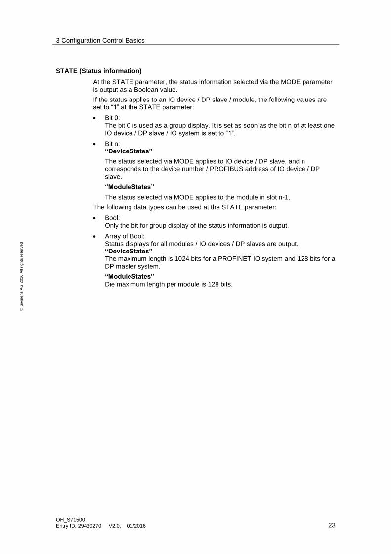
STATE (Status information)
At the STATE parameter, the status information selected via the MODE parameter is output as a Boolean value.
If the status applies to an IO device / DP slave / module, the following values are set to “1” at the STATE parameter:
Bit 0: The bit 0 is used as a group display. It is set as soon as the bit n of at least one IO device / DP slave / IO system is set to “1”.
Bit n: “DeviceStates”
The status selected via MODE applies to IO device / DP slave, and n corresponds to the device number / PROFIBUS address of IO device / DP slave.
“ModuleStates”
The status selected via MODE applies to the module in slot n-1.
The following data types can be used at the STATE parameter:
Bool: Only the bit for group display of the status information is output.
Array of Bool: Status displays for all modules / IO devices / DP slaves are output. “DeviceStates” The maximum length is 1024 bits for a PROFINET IO system and 128 bits for a DP master system.
“ModuleStates”
Die maximum length per module is 128 bits.

4 Principle of Operation and Parameterization
OH_S71500 Entry ID: 29430270, V2.0, 01/2016 24
S
iem
en
s A
G 2
01
6 A
ll ri
gh
ts r
ese
rve
d
4 Principle of Operation and Parameterization
4.1 General overview
Externally, the application example consists of multiple functions/program blocks:
FB 3 “ohConfigCtrl”: Function block of the OH_S71x00_Library for writing the
control data record.
FB 10 “ohDiag” function block for extended diagnostics of the configuration via the “DeviceStates” and “ModuleStates” function blocks.
Startup OB: Call of FB 3 for first commissioning by the central processing unit and ET 200SP.
OB 1: Simulated changes of variations during muffin production by repeated calls of FB 3.
PLC data structures, "OH_record_196_S71500central" and "OH_record_196_ET200SP", as a template for the control data records.
The “ohDataset” data block is used for data management (central database).
4.2 Program overview
Diagrammatic representation
Figure 4-1
ohConfigCtrlOB 1
Startup
WRREC ohDataset
Application program Block of
library
Block of
system
Block of
data management
ohDiagDevice
States
Module
States
ohDiagStates

4 Principle of Operation and Parameterization
OH_S71500 Entry ID: 29430270, V2.0, 01/2016 25
S
iem
en
s A
G 2
01
6 A
ll ri
gh
ts r
ese
rve
d
Complete overview of the program blocks
Table 4-1
Symbolic name Description Type
Startup OB Creates a defined initial state for configuration control.
OB (LAD)
OB 1 (Main) Block to operate the application: When the muffin variation is changed, "configuration control" is used.
OB (LAD)
ohConfigCtrl Writes the control data record to the module. FB (SCL)
WRREC System function to write the data record. SFC
ohDataset Central database for the control data records. DB
ohDiag Bundles the diagnostics in a function block FB (SCL)
ModuleStates System function used for module status diagnostics.
FC
DeviceStates System function used for diagnostics of IO systems.
FC
ohDiagStates Central database for diagnostics. DB
The “ohDataset” data block
The “ohDataset” data block (DB) is the central database of the application. It contains all control data records for configuration control.
Three control data records for the ET 200SP - due to the different hardware configurations of the muffin variations (stored in an array).
One control data record for the S7-1500 for hiding the configured IO modules.
In addition to the above-listed data, the DB also contains status bytes. They allow you to see whether writing the control data record has been completed successfully or with an error.
Figure 4-2
Note The ready-made PLC data structures from the “ohConfigCtrl” library were used to create the control data records. In specific terms, these are the PLC data types "OH_record_196_ET200SP" and "OH_record_196_S71500central".
The muffin variation is selected with the HMI. For this purpose, the „Variants“ tag is linked with the HMI visualization and stores the selected muffin variation numerically. This value corresponds to the respective field number from the "OH_ET200SP" array.
Note The „Variants“ tag must be stored with the attribute "remanent" in the data block to avoid data loss in case of power failure.

4 Principle of Operation and Parameterization
OH_S71500 Entry ID: 29430270, V2.0, 01/2016 26
S
iem
en
s A
G 2
01
6 A
ll ri
gh
ts r
ese
rve
d
The “ohDiagStates” data block
The “ohDiagStates” data block contains all status information of the diagnostics from the „ohDiag“ FB.
A struct (“ModuleStates”) used to operate parameters of the “ModuleStates” FB
A struct (“DeviceStates”) used to operate parameters of the “DeviceStates” FB
Apart from the status information, the DB also contains the selection for the mode of the diagnostics blocks (see Table 3-2).
The following figure shows the structs of the “ohDiagStates” data block.
Figure 4-3
The “ohConfigCtrl” library block
The function block and the associated PLC data types will not be described in detail at this point. More information on the blocks of the OH_S71x00_Library can be found in the
library description on the same HTML page as this document (see \2\).
The “ohDiag” function block
The “ohDiag” function block is used for the extended configuration diagnostics. For this purpose, the “ModuleStates” und “DeviceStates” function blocks are called (see Chapter 3.3).
The following figure shows the call of the “ohDiag” function block in OB 1.
Figure 4-4

4 Principle of Operation and Parameterization
OH_S71500 Entry ID: 29430270, V2.0, 01/2016 27
S
iem
en
s A
G 2
01
6 A
ll ri
gh
ts r
ese
rve
d
Startup OB
When the CPU has been switched on, it executes a startup program - if there is one - in the so-called startup OBs before it starts executing the user program.
For configuration control in central configuration, it is essential that a valid control data record is sent to the CPU already in the startup program. Otherwise, the CPU returns to STOP mode.
In this application, two control data records are sent already in the startup OB.
Control data record for the S7-1500 for declaration of the configured IO modules as "non-existent" (for more information, please refer to Chapter 4.3.1).
Figure 4-5
Control data record for the ET 200SP that contains the slot assignment of the real hardware configuration. Der Hardware configuration for the first commissioning corresponds to the Variant 1 (for more information, please refer to Chapter 4.3.2 and Chapter5.1).
Figure 4-6
4 Principle of Operation and Parameterization
OH_S71500 Entry ID: 29430270, V2.0, 01/2016 28
S
iem
en
s A
G 2
01
6 A
ll ri
gh
ts r
ese
rve
d
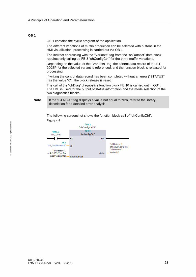
OB 1
OB 1 contains the cyclic program of the application.
The different variations of muffin production can be selected with buttons in the HMI visualization; processing is carried out via OB 1.
The indirect addressing with the "Variants" tag from the “ohDataset” data block requires only calling up FB 3 “ohConfigCtrl” for the three muffin variations.
Depending on the value of the "Variants" tag, the control data record of the ET 200SP for the selected variant is referenced, and the function block is released for processing.
If writing the control data record has been completed without an error ("STATUS" has the value "0"), the block release is reset.
The call of the “ohDiag“ diagnostics function block FB 10 is carried out in OB1. The HMI is used for the output of status information and the mode selection of the two diagnostics blocks.
Note If the "STATUS" tag displays a value not equal to zero, refer to the library description for a detailed error analysis.
The following screenshot shows the function block call of “ohConfigCtrl”:
Figure 4-7

4 Principle of Operation and Parameterization
OH_S71500 Entry ID: 29430270, V2.0, 01/2016 29
S
iem
en
s A
G 2
01
6 A
ll ri
gh
ts r
ese
rve
d
4.3 Control data records
The control data records are the basis for configuration control. They contain the configurable assignment of configured to physically existing station modules.
For each module, the structure of the control data record is predefined and must not be changed.
4.3.1 Control data record for the S7-1500
Representation
To demonstrate configuration control for central configuration, the S7-1500 station is configured with any input and output modules. However, these modules do not exist in the real configuration.
Therefore, the configured IO modules have to be declared as "non-existent" via the control data record.
The graphic representation below shows the configuration of the S7-1500 in TIA Portal and the required control data record:
Figure 4-8
Maximum configuration TIA-Portal Real se t configuration
Control data record
Description
IO modules that do not exist in the real configuration are encoded in the control data record in the appropriate slot with the value "255".
The values for the power module (slot 0; value "0") and the CPU (slot 1, value "1") indicate the real slot and must not be changed.

4 Principle of Operation and Parameterization
OH_S71500 Entry ID: 29430270, V2.0, 01/2016 30
S
iem
en
s A
G 2
01
6 A
ll ri
gh
ts r
ese
rve
d
4.3.2 Control data records for the ET 200SP
Representation
Depending on the muffin production variant, the ET 200SP is equipped with different input and output modules.
For each variant, a separate control data record is required to transfer the assignment between the configured configuration and the physically existing configuration to the interface module.
IO modules not required by a muffin variation must be declared as "unused".
IO modules whose slot in the real configuration differs from the one in the configured configuration must be specified with the real slot number.
Note The server module does not exist in the control data record and must always be configured in the hardware configuration and inserted in the real configuration.
The following graphics show the configuration of the ET 200SP in TIA Portal and the required control data records for the three variations:
Variant 1
Variant 1 produces muffins without decorations and without packaging. This variant requires only the "baking unit" (module 1 in slot 1). Modules that are not required are declared as "unused" by the value "0".
Figure 4-9
Variant 1
Baking
E/A-Module
1
ET 200SP
Project
CPU
Maximum configuration TIA-Portal Real set configuration
Control data record

4 Principle of Operation and Parameterization
OH_S71500 Entry ID: 29430270, V2.0, 01/2016 31
S
iem
en
s A
G 2
01
6 A
ll ri
gh
ts r
ese
rve
d
Variant 2:
Variant 2 produces muffins without decorations but with packaging. This variant requires the "baking unit" (module 1 in slot 1) and the packaging unit (module 3 now in slot 2). The decorating module that is not required is declared as "unused" by the value "0".
Figure 4-10
Maximum configuration TIA-Portal Real set configuration
Control data record
Variant 2
E/A-Modul e1
CPU
Project
PackagingBaking
E/A-Module 3
ET 200SP

4 Principle of Operation and Parameterization
OH_S71500 Entry ID: 29430270, V2.0, 01/2016 32
S
iem
en
s A
G 2
01
6 A
ll ri
gh
ts r
ese
rve
d
Variant 3:
Variant 3 produces muffins with decorations and with packaging. This variant requires all units.
Figure 4-11
Maximum configuration TIA-Portal Real set configuration
Control data record
Variant 3
E/A-Module 1ET 200SP
Project
CPU
Baking Packaging
E/A-Module 3
Decorating
E/A-Module 2
Description
IO modules that do not exist in the real configuration are encoded in the control data record in the appropriate slot with the value "0".
For IO modules where the real slot and the configured one are identical, the current slot number is specified.
For IO modules whose slot in the real configuration differs from the one in the configured configuration, the (new) real slot number must be specified.

5 Installation and Commissioning
OH_S71500 Entry ID: 29430270, V2.0, 01/2016 33
S
iem
en
s A
G 2
01
6 A
ll ri
gh
ts r
ese
rve
d
5 Installation and Commissioning This chapter describes the steps necessary to start up the example using the code from the download and the hardware list.
Note This application does not use a real panel. TIA WinCC Runtime is used for HMI visualization.
5.1 Installing the hardware
Overview of the initial configuration/variant 1
The figure below shows the hardware configuration of the application for first commissioning/muffin production, variant 1.
Figure 5-1
PROFINET IE
S7-1516-3 PN/DP
DI 8x24VDC
Configuration at start / Variante1
PG
ET 200SP
24V
24V
TIA-ProjectCharge/ operation

5 Installation and Commissioning
OH_S71500 Entry ID: 29430270, V2.0, 01/2016 34
S
iem
en
s A
G 2
01
6 A
ll ri
gh
ts r
ese
rve
d
Overview of variant 2 and variant 3
The figure below shows the hardware configuration of the application for muffin production: variant 2 and variant 3.
Figure 5-2
S7-1516-3 PN/DP
DI 8x24VDCDQ 8x24VDC/0.5A
Variant 2
ET 200SP
24V
24V
S7-1516-3 PN/DP
DI 8x24VDC
DQ 8x24VDC/0.5A
Variant 3
ET 200SP
24V
24V
DQ 4x24VDC/2A
PROFINET IE
PG
operation
PROFINET IE
PG
operation
Installation for first commissioning
As the initial configuration, set up the hardware in the production plant according to variant 1.
1. Supply power to the CPU, the ET 200SP and, if necessary, the PG.
2. If necessary, mount the ET 200SP onto a DIN rail and assemble the device as follows:
a. The interface module.
b. The DI 8x24VDC IO module; plugged onto a white BaseUnit (new load group).
c. The server module that completes setting up the ET 200SP.
3. Connect the ET 200SP to the CPU (RJ45) via PROFINET. To do this, use port 1 of interface 1 (X1) of the CPU.
4. Connect the PG to the CPU (RJ45) via Ethernet. To do this, use port 2 of interface 1 (X1) of the CPU.
Note Always follow the installation guidelines for all components.

5 Installation and Commissioning
OH_S71500 Entry ID: 29430270, V2.0, 01/2016 35
S
iem
en
s A
G 2
01
6 A
ll ri
gh
ts r
ese
rve
d
5.2 Installing TIA Portal
1. Install STEP 7 V14 on your programming unit. Follow the instructions of the program.
2. Download the sample application to your programming unit and unzip the 29430270_OH_S71500_APPL_CODE_V10.zip archive.
3. Open the TIA Portal project.
5.3 Commissioning
5.3.1 IP address assignment
Overview
In the application example, the following IP addresses are used:
Table 5-1
Component IP address Subnet mask
PG 192.168.0.3
255.255.255.0 CPU S7 1516-3 PN/DP 192.168.0.1
ET 200SP 192.168.0.2
Change the network setting on the PC to the IP address assigned to it.
Assigning the IP address to the CPU/ET 200SP
To assign the specified IP address to the CPU/ET 200SP, proceed as follows:
1. Open the Project view of TIA Portal and in the project tree, click the "Online access" folder.
2. Click the arrow icon to the left of the interface to show all objects located below the interface.
3. Double-click the "Update accessible devices" command below the interface.
Result: All devices that can be accessed through this interface are displayed in the project tree.
5 Installation and Commissioning
OH_S71500 Entry ID: 29430270, V2.0, 01/2016 36
S
iem
en
s A
G 2
01
6 A
ll ri
gh
ts r
ese
rve
d
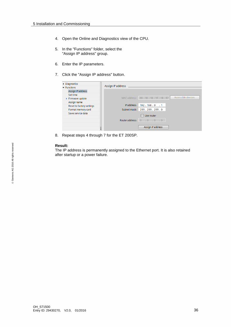
4. Open the Online and Diagnostics view of the CPU.
5. In the "Functions" folder, select the "Assign IP address" group.
6. Enter the IP parameters.
7. Click the "Assign IP address" button.
8. Repeat steps 4 through 7 for the ET 200SP.
Result: The IP address is permanently assigned to the Ethernet port. It is also retained after startup or a power failure.
5 Installation and Commissioning
OH_S71500 Entry ID: 29430270, V2.0, 01/2016 37
S
iem
en
s A
G 2
01
6 A
ll ri
gh
ts r
ese
rve
d
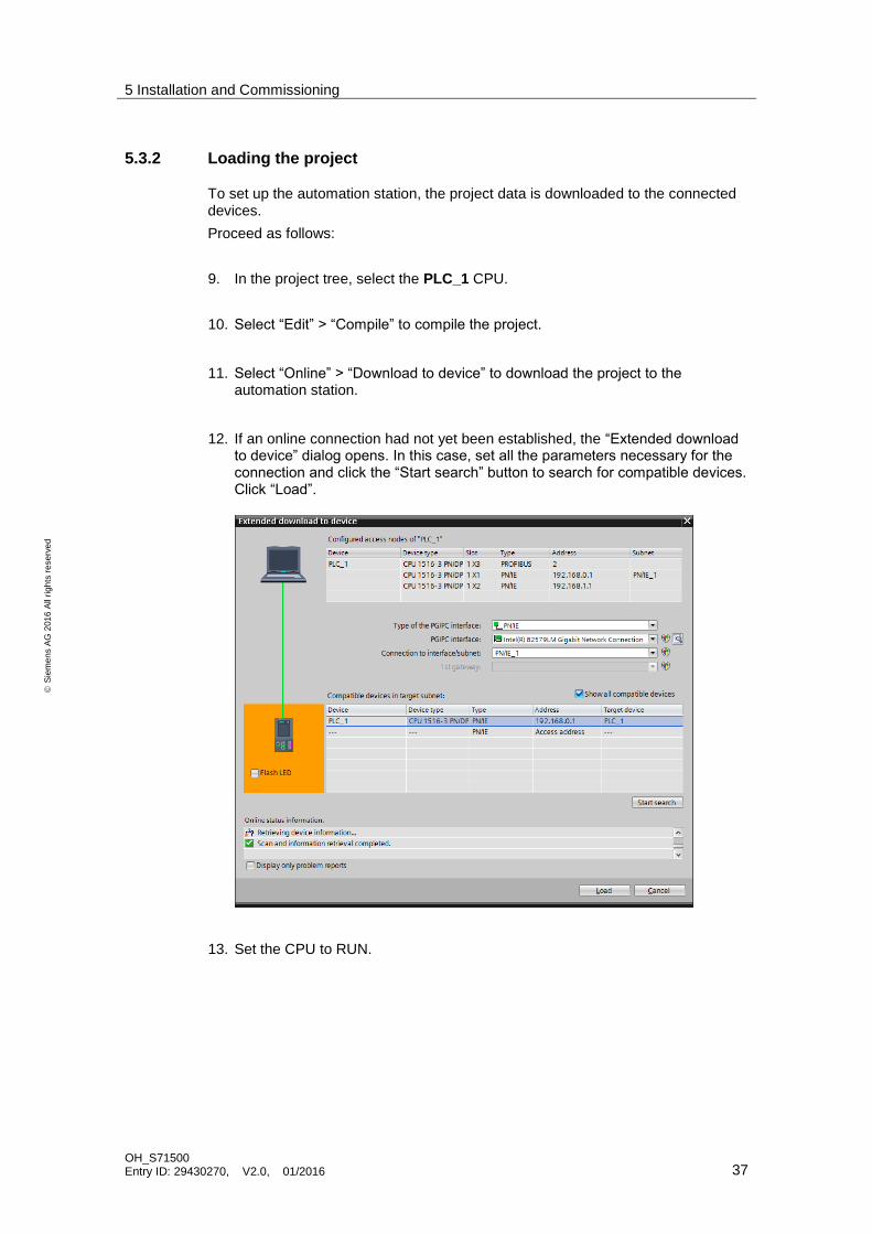
5.3.2 Loading the project
To set up the automation station, the project data is downloaded to the connected devices.
Proceed as follows:
9. In the project tree, select the PLC_1 CPU.
10. Select “Edit” > “Compile” to compile the project.
11. Select “Online” > “Download to device” to download the project to the automation station.
12. If an online connection had not yet been established, the “Extended download to device” dialog opens. In this case, set all the parameters necessary for the connection and click the “Start search” button to search for compatible devices. Click “Load”.
13. Set the CPU to RUN.

6 Operating the Application
OH_S71500 Entry ID: 29430270, V2.0, 01/2016 38
S
iem
en
s A
G 2
01
6 A
ll ri
gh
ts r
ese
rve
d
6 Operating the Application
HMI visualization
The application is controlled with the HMI visualization integrated in the project.
Mark the HMI in the project navigation and start Runtime with the respective icon in the menu bar.
Initial configuration/variant 1
For first commissioning, the ET 200SP was equipped with the modules for variant 1 and, in OB 100, the appropriate control data record was transferred to the interface module.
Variant 2
To produce muffins according to variant 2, proceed as follows:
14. Switch off the power supply of the ET 200SP.
15. Re-equip the hardware of the ET 200SP distributed IO device according to variant 2.
S7-1516-3 PN/DP
DI 8x24VDCDQ 8x24VDC/0.5A
Variant 2
ET 200SP
24V
24V
PROFINET IE
PG
operation
16. Switch the power supply of the ET 200SP back on.
Result: The CPU and the interface module signal an error as the real hardware configuration does not match the configured one.

6 Operating the Application
OH_S71500 Entry ID: 29430270, V2.0, 01/2016 39
S
iem
en
s A
G 2
01
6 A
ll ri
gh
ts r
ese
rve
d
17. Activate the button for variant 2 in the HMI visualization.
Result: The control data record for the slot assignment for variant 2 has been sent to the interface module. When the write operation was successful (the value of the “ohDataset”.OH_ET200SP_Status[1] tag is "0"), the error LED goes out.
Note If the “ohDataset”.OH_ET200SP_Status[1] tag displays a value not equal to zero, refer to the library description for a detailed error analysis.

6 Operating the Application
OH_S71500 Entry ID: 29430270, V2.0, 01/2016 40
S
iem
en
s A
G 2
01
6 A
ll ri
gh
ts r
ese
rve
d
Variant 3
To produce muffins according to variant 3, proceed as follows:
1. Switch off the power supply of the ET 200SP.
2. Re-equip the hardware of the ET 200SP distributed IO device according to variant 3.
S7-1516-3 PN/DP
DI 8x24VDC
DQ 8x24VDC/0.5A
Variant 3
ET 200SP
24V
24V
DQ 4x24VDC/2A
PROFINET IE
PG
operation
3. Switch the power supply of the ET 200SP back on.
Result: The CPU and the interface module signal an error as the real hardware configuration does not match the configured one.

6 Operating the Application
OH_S71500 Entry ID: 29430270, V2.0, 01/2016 41
S
iem
en
s A
G 2
01
6 A
ll ri
gh
ts r
ese
rve
d
4. Activate the button for variant 3 in the HMI visualization.
Result: The control data record for the slot assignment for variant 3 has been sent to the interface module. When the write operation was successful (the value of the “ohDataset”.OH_ET200SP_Status[2] tag is "0"), the error LED goes out.
Note If the “ohDataset”.OH_ET200SP_Status[2] tag displays a value not equal to zero, refer to the library description for a detailed error analysis.
6 Operating the Application
OH_S71500 Entry ID: 29430270, V2.0, 01/2016 42
S
iem
en
s A
G 2
01
6 A
ll ri
gh
ts r
ese
rve
d
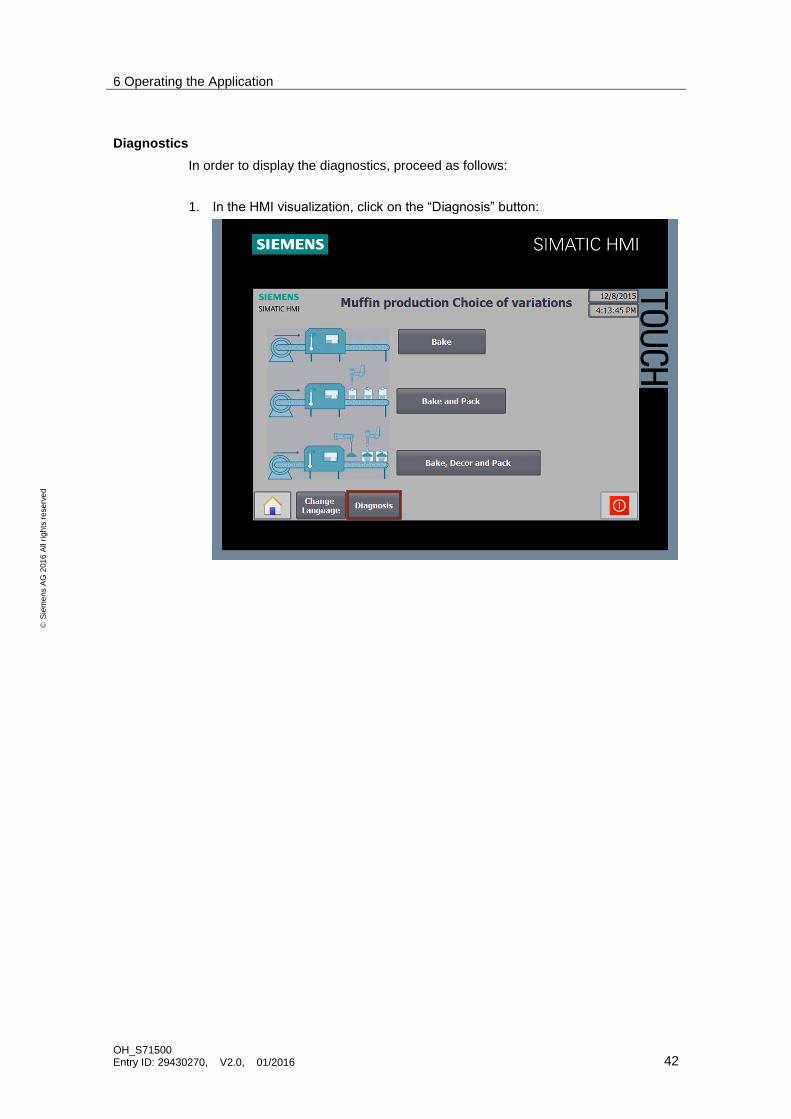
Diagnostics
In order to display the diagnostics, proceed as follows:
1. In the HMI visualization, click on the “Diagnosis” button:

6 Operating the Application
OH_S71500 Entry ID: 29430270, V2.0, 01/2016 43
S
iem
en
s A
G 2
01
6 A
ll ri
gh
ts r
ese
rve
d
2. You are now on the diagnostics page.
The following points explain the diagnostics display and how you can adjust the diagnostics.
1. Input of the HW identifier, which IO system is diagnosed. The HW identifier can be found in “PLC tags” > “System constants”.
Note For the PROFINET IO system diagnostics with the “DeviceStates” function block, the data type of the HW identifier used must be “HW_IoSystem”.
2. Selecting the mode (“DeviceStates”).
3. Input of the HW identifier, which module is diagnosed The HW identifier can be found in “PLC tags” > “System constants”.
Note For the diagnostics of the modules with the “ModuleStates” function block, the data type of the HW identifier used must be “HW_Device”.
4. Selecting the mode (“ModuleStates”).
Note More information on the diagnostics can be found in Chapterl 3.3.
1
2
4
3
7 Links & Literature
OH_S71500 Entry ID: 29430270, V2.0, 01/2016 44
S
iem
en
s A
G 2
01
6 A
ll ri
gh
ts r
ese
rve
d
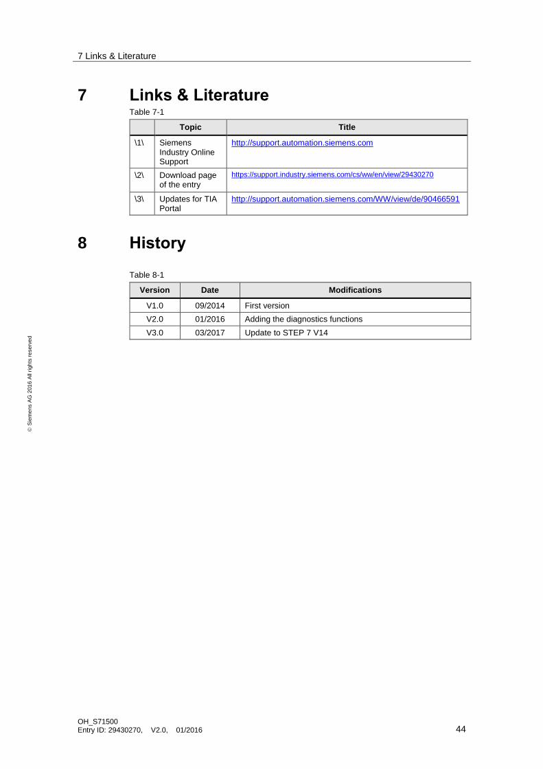
7 Links & Literature Table 7-1
Topic Title
\1\ Siemens Industry Online Support
http://support.automation.siemens.com
\2\ Download page of the entry
https://support.industry.siemens.com/cs/ww/en/view/29430270
\3\ Updates for TIA Portal
http://support.automation.siemens.com/WW/view/de/90466591
8 History
Table 8-1
Version Date Modifications
V1.0 09/2014 First version
V2.0 01/2016 Adding the diagnostics functions
V3.0 03/2017 Update to STEP 7 V14


