47
https://support.industry.siemens.com/cs/ww/en/view/86302104 Application example 05/2016 Plant Data Interface for the Food & Beverage Industry Interface description based on OMAC

https://support.industry.siemens.com/cs/ww/en/view/86302104
Application example 05/2016
Plant Data Interface for the Food & Beverage Industry Interface description based on OMAC
Warranty and liability
Plant Data Interface - OMAC Entry-ID: 86302104, V2.0, 05/2016 2
S
iem
en
s A
G 2
01
6 A
ll ri
gh
ts r
ese
rve
d
Warranty and liability
Note The Application Examples are not binding and do not claim to be complete regarding the circuits shown, equipping and any eventuality. The Application Examples do not represent customer-specific solutions. They are only intended to provide support for typical applications. You are responsible for ensuring that the described products are used correctly. These Application Examples do not relieve you of the responsibility to use safe practices in application, installation, operation and maintenance. When using these Application Examples, you recognize that we cannot be made liable for any damage/claims beyond the liability clause described. We reserve the right to make changes to these Application Examples at any time without prior notice. If there are any deviations between the recommendations provided in these Application Examples and other Siemens publications – e.g. Catalogs – the contents of the other documents have priority.
We do not accept any liability for the information contained in this document. Any claims against us – based on whatever legal reason – resulting from the use of the examples, information, programs, engineering and performance data etc., described in this Application Example shall be excluded. Such an exclusion shall not apply in the case of mandatory liability, e.g. under the German Product Liability Act (“Produkthaftungsgesetz”), in case of intent, gross negligence, or injury of life, body or health, guarantee for the quality of a product, fraudulent concealment of a deficiency or breach of a condition which goes to the root of the contract (“wesentliche Vertragspflichten”). The damages for a breach of a substantial contractual obligation are, however, limited to the foreseeable damage, typical for the type of contract, except in the event of intent or gross negligence or injury to life, body or health. The above provisions do not imply a change of the burden of proof to your detriment. Any form of duplication or distribution of these Application Examples or excerpts hereof is prohibited without the expressed consent of the Siemens AG.
Security informa-tion
Siemens provides products and solutions with industrial security functions that support the secure operation of plants, systems, machines and networks. In order to protect plants, systems, machines and networks against cyber threats, it is necessary to implement – and continuously maintain – a holistic, state-of-the-art industrial security concept. Siemens’ products and solutions only form one element of such a concept. Customer is responsible to prevent unauthorized access to its plants, systems, machines and networks. Systems, machines and components should only be connected to the enterprise network or the internet if and to the extent necessary and with appropriate security measures (e.g. use of firewalls and network segmentation) in place. Additionally, Siemens’ guidance on appropriate security measures should be taken into account. For more information about industrial security, please visit http://www.siemens.com/industrialsecurity.
Siemens’ products and solutions undergo continuous development to make them more secure. Siemens strongly recommends to apply product updates as soon as available and to always use the latest product versions. Use of product versions that are no longer supported, and failure to apply latest updates may increase customer’s exposure to cyber threats. To stay informed about product updates, subscribe to the Siemens Industrial Security RSS Feed under http://www.siemens.com/industrialsecurity.
Table of contents
Plant Data Interface - OMAC Entry-ID: 86302104, V2.0, 05/2016 3
S
iem
en
s A
G 2
01
6 A
ll ri
gh
ts r
ese
rve
d
Table of contents Warranty and liability ................................................................................................... 2
1 Overview of a plant wide automation concept ............................................... 4
1.1 Overview Plant Wide Concepts for Food and Beverage Industry ........ 4 1.2 Layout overview for plant wide data interface ...................................... 4 1.3 Definitions ............................................................................................. 5 1.3.1 Default values ....................................................................................... 5 1.3.2 Data types ............................................................................................ 6 1.4 PDI Overview ....................................................................................... 7 1.4.1 PDI Basic .............................................................................................. 7 1.4.2 PDI LCU ............................................................................................... 7 1.4.3 PDI PEC ............................................................................................... 8 1.4.4 PDI Para ............................................................................................... 8
2 Interface descriptions based on OMAC .......................................................... 9
2.1 PDI Basic .............................................................................................. 9 2.1.1 Interface description detailed information .......................................... 12 2.2 PDI LCU ............................................................................................. 20 2.2.1 Interface description overview ............................................................ 21 2.2.2 Interface description detailed information .......................................... 22 2.2.3 Handshake for state change .............................................................. 27 2.3 PDI PEC ............................................................................................. 31 2.3.1 Interface description overview ............................................................ 32 2.3.2 Interface description detailed information .......................................... 33 2.3.3 Energy Interface Add-on .................................................................... 36 2.4 PDI Para ............................................................................................. 37 2.4.1 Interface description overview ............................................................ 37 2.4.2 Interface description detailed information .......................................... 37
3 General PDI Information.................................................................................. 39
3.1 Technical Implementation .................................................................. 39 3.1.1 STEP 7 (S7-300 / S7-400) ................................................................. 39 3.1.2 TIA Portal (S7-300 / S7-400 / S7-1200 / S7-1500) ............................ 39 3.1.3 SIMOTION SCOUT ............................................................................ 40 3.2 State description ................................................................................. 40 3.3 Cross naming reference (system wide) .............................................. 43
4 Abbreviations ................................................................................................... 46
5 Related literature ............................................................................................. 47
6 History............................................................................................................... 47

1 Overview of a plant wide automation concept
Plant Data Interface - OMAC Entry-ID: 86302104, V2.0, 05/2016 4
S
iem
en
s A
G 2
01
6 A
ll ri
gh
ts r
ese
rve
d
1 Overview of a plant wide automation concept
1.1 Overview Plant Wide Concepts for Food and Beverage Industry
In the Food & Beverage Industry is substantial room for improvement, to increase the efficiency and effectiveness of existing and planned new production lines.
An essential contribution to this will provide the integrated linking of production lines and machines from the inbound of raw material to production, packaging up to the outgoing goods, as well as the consistent recording of production parameters like quantities, machine time, etc. These data can be analyzed at management systems and sustainable measures for improvement can be initiated.
Today this partly causes big efforts, because machines and components of different manufacturers have to be linked and the collected data has to be synchronized. Therefore a plant wide integration concept for line integration from Siemens AG includes the machine level, supervisory systems up to MES (Manufacturing Execution System) from incoming goods across food processing and food packaging areas to outgoing goods and storage.
This concept contains different modules such as Line Monitoring, Line Control, Line HMI (Human Machine Interface), plant energy, and so on. One such module is the machine interface, which is described herein.
1.2 Layout overview for plant wide data interface
The following picture shows the automation information flow related to the Plant Data Interface (PDI) between PSS (Plant Supervisory System), LCU (Line Control Unit) and OEMs’ (Original Equipment Manufacturer) machine PLC (Programmable Logic Controller).
PDI - Plant Data Interface
S7 1500S7 300 SIMOTION
Line Control Unit
Line HMI (WinCC)
HMI Server
1 Overview of a plant wide automation concept
Plant Data Interface - OMAC Entry-ID: 86302104, V2.0, 05/2016 5
S
iem
en
s A
G 2
01
6 A
ll ri
gh
ts r
ese
rve
d
Four data-interfaces exist in the current architecture, PDI Basic, PDI Para, PDI LCU and PDI PEC, when combined they are referred as the Plant Data Interface or PDI. The PDI Basic provides the necessary information for Line Visualization and Line Monitoring (LM). The PDI LCU contains only information required for Line Control. The PDI PEC gives information about energy consumption. PDI Para is a data interface for additional data of machine specific parameters.
The PDI will be available in 2 different versions. One version is currently available for OMAC (Organization for Machine Automation and Control), which is described here and another version is available for Weihenstephan and is described in additional documentation.
1.3 Definitions
1.3.1 Default values
All values and counters that are not used or cannot be provided due to an out-of-range or undefined condition are set to “–1” or in case of type STRING to “”. Counters are always 0 or positive”.
Mandatory values for the different end customer functions are marked by function.
1 Overview of a plant wide automation concept
Plant Data Interface - OMAC Entry-ID: 86302104, V2.0, 05/2016 6
Siemens AG 2016 All rights reserved
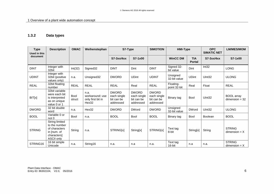
1.3.2 Data types
Type
Used in this document
Description OMAC Weihenstephan S7-Type SIMOTION HMI-Type OPC SIMATIC NET
LM/MES/MOM
S7-3xx/4xx S7-1x00 WinCC DM TIA Portal
S7-3xx/4xx S7-1x00
DINT Integer with 32bit
Int(32) Signed32 DINT Dint DINT Signed 32-bit value
Dint Int32
LONG
UDINT Integer with 32bit (positive values only)
n.a. Unsigned32 DWORD UDint UDINT Unsigned 32-bit value
UDint UInt32 ULONG
REAL 32bit floating number
REAL REAL REAL Real REAL Floating-point 32-bit
Real Float REAL
BIT[x]
32bit variable were each bit is interpreted as on unique value 0 or 1
Bool struct
n.a. workaround: use only first bit in Hex32
DWORD each single bit can be addressed
DWORD each single bit can be addressed
DWORD each single bit can be addressed
Binary tag Bool UInt32 BOOL array dimension = 32
DWORD 32 bit double word
n.a. Hex32 DWORD DWord DWORD Unsigned 32-bit value
DWord UInt32 ULONG
BOOL Variable 0 or not 0
Bool n.a. BOOL Bool BOOL Binary tag Bool Boolean BOOL
STRING
String limited to the number of characters in [num. of characters] ASCII only
String n.a. STRING[x] String[x] STRING[x] Text tag 8-bit
String[x] String STRING dimension = X
STRING16 16 bit simple Unicode
n.a. String16 n.a. n.a n.a. Text tag 16-bit
n.a n.a. STRING dimension = X

1 Overview of a plant wide automation concept
Plant Data Interface - OMAC Entry-ID: 86302104, V2.0, 05/2016 7
S
iem
en
s A
G 2
01
6 A
ll ri
gh
ts r
ese
rve
d
1.4 PDI Overview
1.4.1 PDI Basic
The basic interface provides basic information regarding the machine, e.g. mode and state, machine speed and counters. The flow of information through the interface is from machine/production level (OEM) upwards to the LCU and/or PSS respectively. There is no data transfer from upper level LCUs/PSSs downwards to the machine/production level (OEM).This information is used for:
Operator information about the machine state for line overviews (HMI), on a line server or an HMI client in a control room.
Line monitoring for basic OEE / KPI (Overall Equipment Effectiveness / Key Performance Indicators) information.
All data exchanged with the PDI Basic are tag based and can be polled by the upper level at any time. The data itself can be written to the interface e.g. as data block in any PLC cycle. All data should however be written simultaneously to the interface to ensure consistency of data.
1.4.2 PDI LCU
The LCU interface provides additional data for line control functionality, e.g. start/stop and set line speed. Machine state information is communicated upwards from machine/production level (OEM) up to the LCU and/or PSS. Control and command data such as machine speed and start/stop are transmitted downwards from upper level LCUs/PSSs to the machine/production level (OEM). The data is used…
to provide operator information about machine speed and entry/exit buffer of single machines on line overview (HMI) screens, on line servers or at HMI clients in a control room
by the Line Control Unit to control the line, in terms of speed, buffer fill-levels and start/stop of machines
All data exchanged with the PDI LCU between line HMI (PSS) and the OEM PLC (Programmable Logic Controller) are tag based and can be polled by upper level systems at any time. Transfer of data between the Line Control Unit and OEM should be performed block-wise to ensure data consistency.
Implementation of the PDI LCU is only required for systems implementing the Line Control Unit. The LCU is an additional package for a plant wide automation that requires additional hardware and software components.
1 Overview of a plant wide automation concept
Plant Data Interface - OMAC Entry-ID: 86302104, V2.0, 05/2016 8
S
iem
en
s A
G 2
01
6 A
ll ri
gh
ts r
ese
rve
d
1.4.3 PDI PEC
The PEC provides additional data for energy monitoring and on top level to support implementation of a corporate energy data management system with following objectives:
Compliance and support of national and international sustainability programs and standards, like ISO50001
Continuous improvement of energy and water conservation
Reduce costs for procurement of energy and water
Increase employee awareness for energy efficiency
All data exchanged with the PDI-PEC between line HMI (PSS) and the OEM PLC are tag based and can be polled by upper level systems at any time. Implementation of the PDI PEC is optional.
1.4.4 PDI Para
The PDI-Para interface provides additional data for machine specific parameters.
The information can be delivered as Boolean, Integer, Real or String values. The delivered information contains typically process, order or reporting information.
Implementation of the PDI Para is optional.

2 Interface descriptions based on OMAC
Plant Data Interface - OMAC Entry-ID: 86302104, V2.0, 05/2016 9
S
iem
en
s A
G 2
01
6 A
ll ri
gh
ts r
ese
rve
d
2 Interface descriptions based on OMAC
2.1 PDI Basic
The basic interface provides basic information regarding machine state and parameters. The information is communicated upwards from machine/production level to the PSS level. There is no data transfer from upper level PSS systems downward to the machine/production level.
This information is used for:
Operator information about machine state on line overview (HMI) screens, on line servers or on HMI clients in a control room. This includes:
– machine state and mode information
– material state information related to the machine
– alarm information
Line monitoring of basic OEE / KPI information
– production results (downtime information, OEE, global efficiency)
– raised alarm hit list
– MTTR (Mean time to repair), MTBF (Mean time between failures
– KPI trends
2 Interface descriptions based on OMAC
Plant Data Interface - OMAC Entry-ID: 86302104, V2.0, 05/2016 10
Siemens AG 2016 All rights reserved
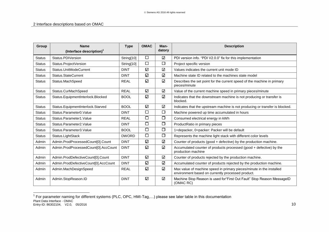
Group Name
(Interface description)1
Type OMAC Man-datory
Description
Status Status.PDIVersion String[10] PDI version info. “PDI V2.0.0” fix for this implementation
Status Status.ProjectVersion String[10] Project specific version
Status Status.UnitModeCurrent DINT Values indicates the current unit mode ID
Status Status.StateCurrent DINT Machine state ID related to the machines state model
Status Status.MachSpeed REAL Describes the set point for the current speed of the machine in primary pieces/minute
Status Status.CurMachSpeed REAL Value of the current machine speed in primary pieces/minute
Status Status.EquipmentInterlock.Blocked BOOL Indicates that the downstream machine is not producing or transfer is blocked.
Status Status.EquipmentInterlock.Starved BOOL Indicates that the upstream machine is not producing or transfer is blocked.
Status Status.Parameter0.Value DINT Machine powered up time accumulated in hours
Status Status.Parameter1.Value REAL Consumed electrical energy in kWh
Status Status.Parameter2.Value DINT ProductRatio in primary pieces
Status Status.Parameter3.Value BOOL 1=depacker, 0=packer: Packer will be default
Status Status.LightStack DWORD Represents the machine light stack with different color levels
Admin Admin.ProdProcessedCount[0].Count DINT Counter of products (good + defective) by the production machine.
Admin Admin.ProdProcessedCount[0].AccCount DINT Accumulated counter of products processed (good + defective) by the production machine
Admin Admin.ProdDefectiveCount[0].Count DINT Counter of products rejected by the production machine.
Admin Admin.ProdDefectiveCount[0].AccCount DINT Accumulated counter of products rejected by the production machine.
Admin Admin.MachDesignSpeed REAL Max value of machine speed in primary pieces/minute in the installed environment based on currently processed product.
Admin Admin.StopReason.ID DINT Machine Stop Reason is used for“First Out Fault” Stop Reason MessageID (OMAC RC)
1 For parameter naming for different systems (PLC, OPC, HMI-Tag,…) please see later table in this documentation
2 Interface descriptions based on OMAC
Plant Data Interface - OMAC Entry-ID: 86302104, V2.0, 05/2016 11
Siemens AG 2016 All rights reserved
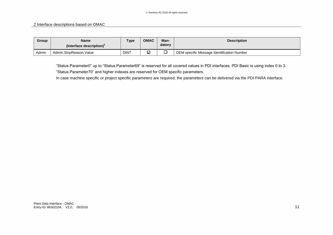
Group Name
(Interface description)1
Type OMAC Man-datory
Description
Admin Admin.StopReason.Value DINT OEM specific Message Identification Number
“Status.Parameter0” up to “Status.Parameter69” is reserved for all covered values in PDI interfaces. PDI Basic is using index 0 to 3.
“Status.Parameter70” and higher indexes are reserved for OEM specific parameters.
In case machine specific or project specific parameters are required, the parameters can be delivered via the PDI PARA interface.
2 Interface descriptions based on OMAC
Plant Data Interface - OMAC Entry-ID: 86302104, V2.0, 05/2016 12
S
iem
en
s A
G 2
01
6 A
ll ri
gh
ts r
ese
rve
d
2.1.1 Interface description detailed information
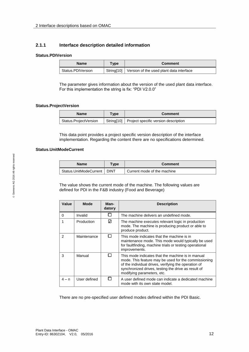
Status.PDIVersion
Name Type Comment
Status.PDIVersion String[10] Version of the used plant data interface
The parameter gives information about the version of the used plant data interface. For this implementation the string is fix: “PDI V2.0.0”
Status.ProjectVersion
Name Type Comment
Status.ProjectVersion String[10] Project specific version description
This data point provides a project specific version description of the interface implementation. Regarding the content there are no specifications determined.
Status.UnitModeCurrent
Name Type Comment
Status.UnitModeCurrent DINT Current mode of the machine
The value shows the current mode of the machine. The following values are defined for PDI in the F&B industry (Food and Beverage)
Value Mode Man-datory
Description
0 Invalid The machine delivers an undefined mode.
1 Production The machine executes relevant logic in production mode. The machine is producing product or able to produce product.
2 Maintenance This mode indicates that the machine is in maintenance mode. This mode would typically be used for faultfinding, machine trials or testing operational improvements.
3 Manual This mode indicates that the machine is in manual mode. This feature may be used for the commissioning of the individual drives, verifying the operation of synchronized drives, testing the drive as result of modifying parameters, etc.
4 – n User defined A user defined mode can indicate a dedicated machine mode with its own state model.
There are no pre-specified user defined modes defined within the PDI Basic.
2 Interface descriptions based on OMAC
Plant Data Interface - OMAC Entry-ID: 86302104, V2.0, 05/2016 13
S
iem
en
s A
G 2
01
6 A
ll ri
gh
ts r
ese
rve
d
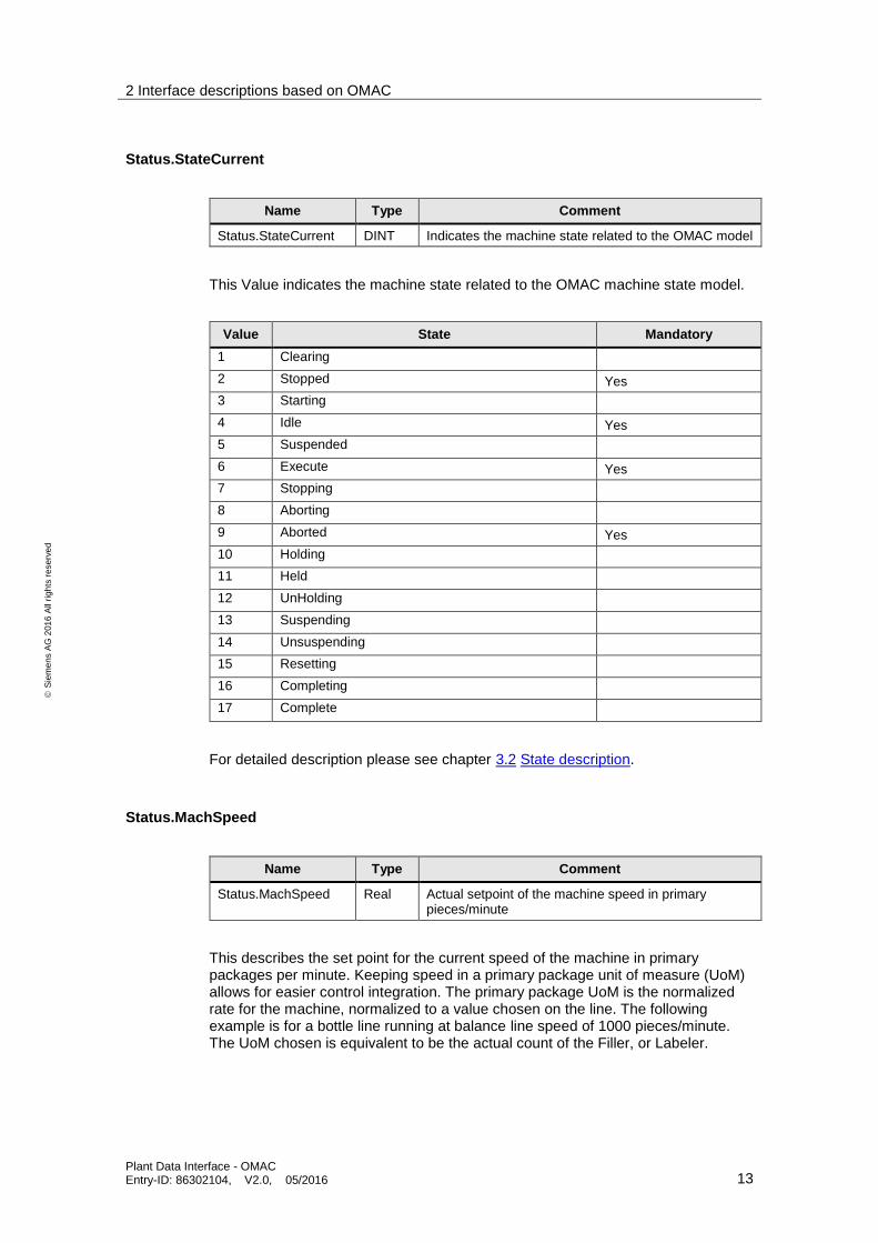
Status.StateCurrent
Name Type Comment
Status.StateCurrent DINT Indicates the machine state related to the OMAC model
This Value indicates the machine state related to the OMAC machine state model.
Value State Mandatory
1 Clearing
2 Stopped Yes
3 Starting
4 Idle Yes
5 Suspended
6 Execute Yes
7 Stopping
8 Aborting
9 Aborted Yes
10 Holding
11 Held
12 UnHolding
13 Suspending
14 Unsuspending
15 Resetting
16 Completing
17 Complete
For detailed description please see chapter 3.2 State description.
Status.MachSpeed
Name Type Comment
Status.MachSpeed Real Actual setpoint of the machine speed in primary pieces/minute
This describes the set point for the current speed of the machine in primary packages per minute. Keeping speed in a primary package unit of measure (UoM) allows for easier control integration. The primary package UoM is the normalized rate for the machine, normalized to a value chosen on the line. The following example is for a bottle line running at balance line speed of 1000 pieces/minute. The UoM chosen is equivalent to be the actual count of the Filler, or Labeler.
2 Interface descriptions based on OMAC
Plant Data Interface - OMAC Entry-ID: 86302104, V2.0, 05/2016 14
S
iem
en
s A
G 2
01
6 A
ll ri
gh
ts r
ese
rve
d
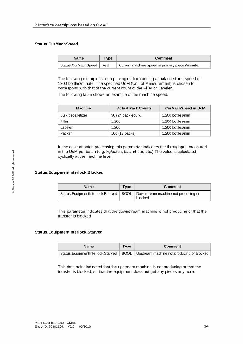
Status.CurMachSpeed
Name Type Comment
Status.CurMachSpeed Real Current machine speed in primary pieces/minute.
The following example is for a packaging line running at balanced line speed of 1200 bottles/minute. The specified UoM (Unit of Measurement) is chosen to correspond with that of the current count of the Filler or Labeler.
The following table shows an example of the machine speed.
Machine Actual Pack Counts CurMachSpeed in UoM
Bulk depalletizer 50 (24 pack equiv.) 1.200 bottles/min
Filler 1.200 1.200 bottles/min
Labeler 1.200 1.200 bottles/min
Packer 100 (12 packs) 1.200 bottles/min
In the case of batch processing this parameter indicates the throughput, measured in the UoM per batch (e.g. kg/batch, batch/hour, etc.).The value is calculated cyclically at the machine level.
Status.EquipmentInterlock.Blocked
Name Type Comment
Status.EquipmentInterlock.Blocked BOOL Downstream machine not producing or blocked
This parameter indicates that the downstream machine is not producing or that the transfer is blocked
Status.EquipmentInterlock.Starved
Name Type Comment
Status.EquipmentInterlock.Starved BOOL Upstream machine not producing or blocked
This data point indicated that the upstream machine is not producing or that the transfer is blocked, so that the equipment does not get any pieces anymore.
2 Interface descriptions based on OMAC
Plant Data Interface - OMAC Entry-ID: 86302104, V2.0, 05/2016 15
S
iem
en
s A
G 2
01
6 A
ll ri
gh
ts r
ese
rve
d
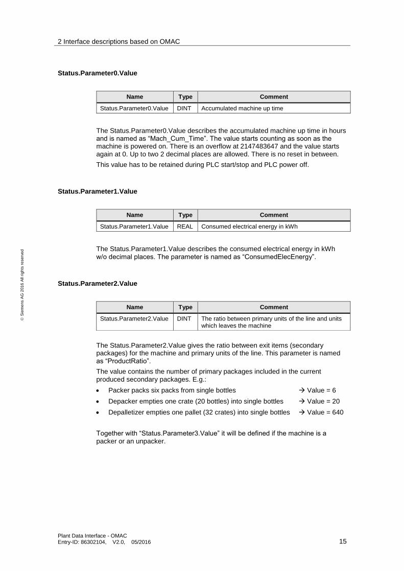
Status.Parameter0.Value
Name Type Comment
Status.Parameter0.Value DINT Accumulated machine up time
The Status.Parameter0.Value describes the accumulated machine up time in hours and is named as “Mach_Cum_Time”. The value starts counting as soon as the machine is powered on. There is an overflow at 2147483647 and the value starts again at 0. Up to two 2 decimal places are allowed. There is no reset in between.
This value has to be retained during PLC start/stop and PLC power off.
Status.Parameter1.Value
Name Type Comment
Status.Parameter1.Value REAL Consumed electrical energy in kWh
The Status.Parameter1.Value describes the consumed electrical energy in kWh w/o decimal places. The parameter is named as “ConsumedElecEnergy”.
Status.Parameter2.Value
The Status.Parameter2.Value gives the ratio between exit items (secondary packages) for the machine and primary units of the line. This parameter is named as “ProductRatio”.
The value contains the number of primary packages included in the current produced secondary packages. E.g.:
Packer packs six packs from single bottles Value = 6
Depacker empties one crate (20 bottles) into single bottles Value = 20
Depalletizer empties one pallet (32 crates) into single bottles Value = 640
Together with “Status.Parameter3.Value” it will be defined if the machine is a packer or an unpacker.
Name Type Comment
Status.Parameter2.Value DINT The ratio between primary units of the line and units which leaves the machine

2 Interface descriptions based on OMAC
Plant Data Interface - OMAC Entry-ID: 86302104, V2.0, 05/2016 16
S
iem
en
s A
G 2
01
6 A
ll ri
gh
ts r
ese
rve
d
Status.Parameter3.Value
Indicates if the machine packs or unpacks pieces. If Value = 0 the machine is a packer. This is the default value. If Value = 1 the machine is an unpacker.
Status.LightStack
The machine light stack provides easy indication of the machine state for operators, based on EN / IEC 60204-1.
Color Meaning Description and operator task Light Signal
Red Emergency Hazardous condition.
Immediate action to deal with hazardous condition (e.g. switch off Energy supply).
Static Bit[0]
Flashing Bit[1]
Yellow Abnormal Abnormal condition impending critical conditions.
Monitoring and/or intervention (e.g. by reestablishing intended function).
Static Bit[2]
Flashing Bit[3]
Blue Mandatory Indication of a condition that requires an operator
action. Static Bit[4]
Flashing Bit[5]
Green Normal Normal condition Static Bit[6]
Flashing Bit[7]
White Neutral Other condition; may be used whenever doubts exist
about the implementation of RED;YELLOW,BLUE or GREEN
Static Bit[8]
Flashing Bit[9]
The light stack is mainly used for the operator to identify required operator intervention at the machine.
The colors red and green are mandatory, all others are optional. Machines where additional colors would be useful should provide them.
NOTE The flashing lights are used for differentiation or highlighting of the signal:
to thrill attention
to request immediate action
to show discrepancy between command and current state
to show change of process (e.g transition)
Name Type Comment
Status.Parameter3.Value BOOL Machine Is a packer or a unpacker
Name Type Comment
Status.LightStack DWORD Machine signal light stack
2 Interface descriptions based on OMAC
Plant Data Interface - OMAC Entry-ID: 86302104, V2.0, 05/2016 17
S
iem
en
s A
G 2
01
6 A
ll ri
gh
ts r
ese
rve
d
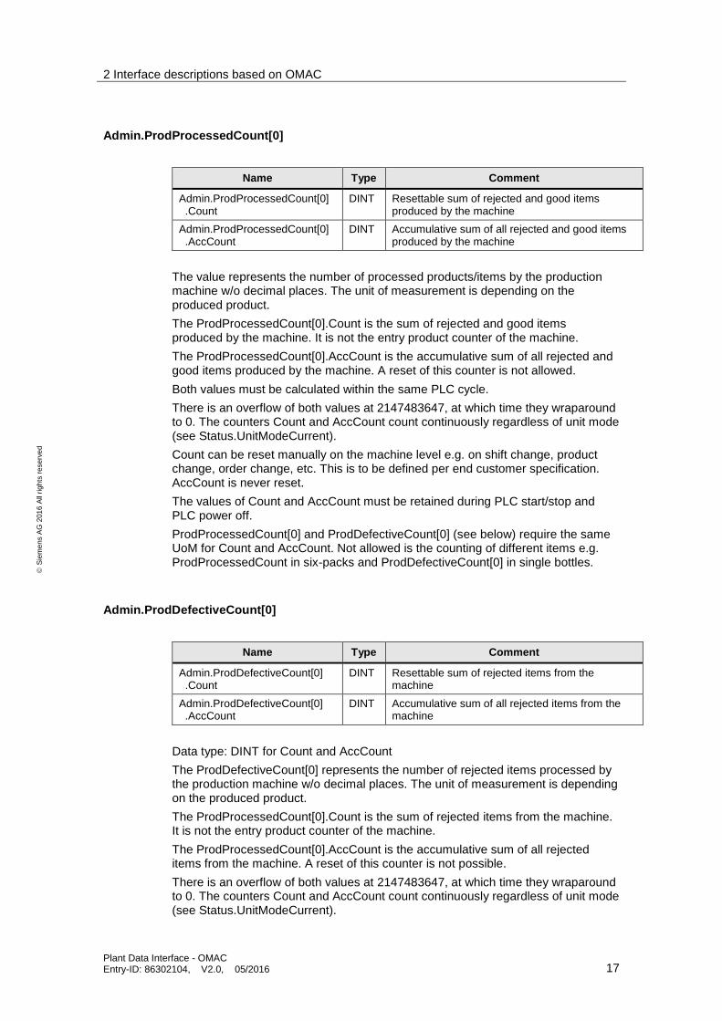
Admin.ProdProcessedCount[0]
The value represents the number of processed products/items by the production machine w/o decimal places. The unit of measurement is depending on the produced product.
The ProdProcessedCount[0].Count is the sum of rejected and good items produced by the machine. It is not the entry product counter of the machine.
The ProdProcessedCount[0].AccCount is the accumulative sum of all rejected and good items produced by the machine. A reset of this counter is not allowed.
Both values must be calculated within the same PLC cycle.
There is an overflow of both values at 2147483647, at which time they wraparound to 0. The counters Count and AccCount count continuously regardless of unit mode (see Status.UnitModeCurrent).
Count can be reset manually on the machine level e.g. on shift change, product change, order change, etc. This is to be defined per end customer specification. AccCount is never reset.
The values of Count and AccCount must be retained during PLC start/stop and PLC power off.
ProdProcessedCount[0] and ProdDefectiveCount[0] (see below) require the same UoM for Count and AccCount. Not allowed is the counting of different items e.g. ProdProcessedCount in six-packs and ProdDefectiveCount[0] in single bottles.
Admin.ProdDefectiveCount[0]
Data type: DINT for Count and AccCount
The ProdDefectiveCount[0] represents the number of rejected items processed by the production machine w/o decimal places. The unit of measurement is depending on the produced product.
The ProdProcessedCount[0].Count is the sum of rejected items from the machine. It is not the entry product counter of the machine.
The ProdProcessedCount[0].AccCount is the accumulative sum of all rejected items from the machine. A reset of this counter is not possible.
There is an overflow of both values at 2147483647, at which time they wraparound to 0. The counters Count and AccCount count continuously regardless of unit mode (see Status.UnitModeCurrent).
Name Type Comment
Admin.ProdProcessedCount[0] .Count
DINT Resettable sum of rejected and good items produced by the machine
Admin.ProdProcessedCount[0] .AccCount
DINT Accumulative sum of all rejected and good items produced by the machine
Name Type Comment
Admin.ProdDefectiveCount[0] .Count
DINT Resettable sum of rejected items from the machine
Admin.ProdDefectiveCount[0] .AccCount
DINT Accumulative sum of all rejected items from the machine
2 Interface descriptions based on OMAC
Plant Data Interface - OMAC Entry-ID: 86302104, V2.0, 05/2016 18
S
iem
en
s A
G 2
01
6 A
ll ri
gh
ts r
ese
rve
d
Count can be reset manually on the machine level e.g. on shift change, product change, order change, etc. This is to be defined per end customer specification. AccCount is never reset.
The counter values must be retained during PLC start/stop and PLC power off.
ProdProcessedCount[0] and ProdDefectiveCount[0] (see below) require the same UoM for Count and AccCount. Not allowed is the counting of different items e.g. ProdProcessedCount in six-packs and ProdDefectiveCount[0] in single bottles.
Admin.MachDesignSpeed
The machine design speed tag represents the maximum design speed of the machine in primary packages per minute for the current product setup.
The machine design speed provided by the machine builder, indicates the speed of the machine, for the given configuration and product selection. In the event, that the maximum machine speed, be downgraded due to the line constellation, any necessary adjustments for OEE or other KPIs, should be made within the line level and not on a machine level.
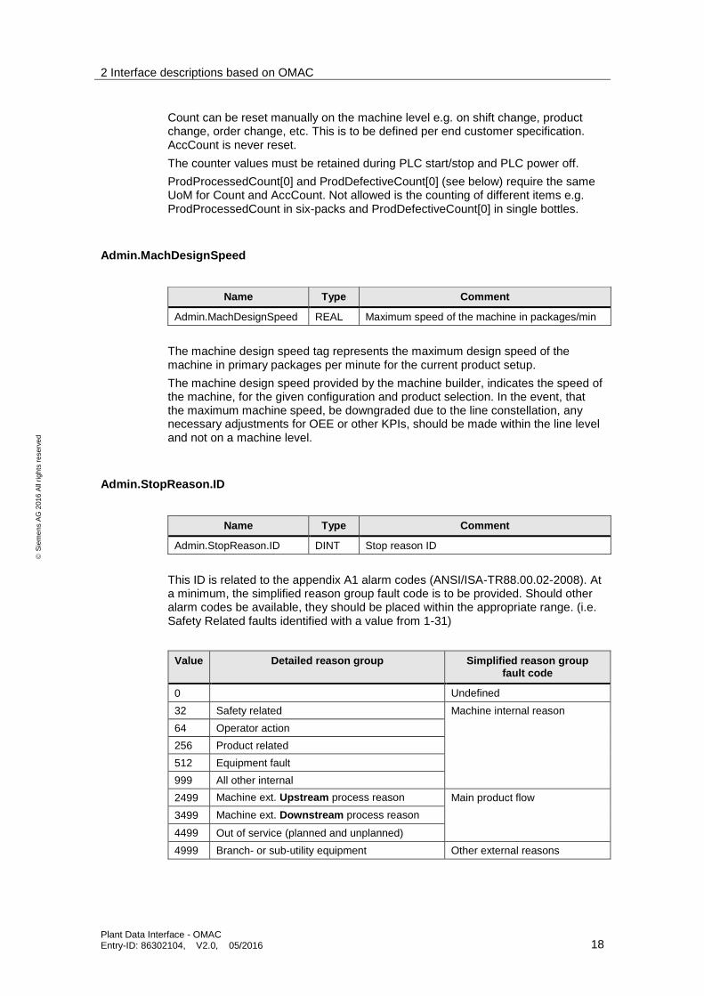
Admin.StopReason.ID
This ID is related to the appendix A1 alarm codes (ANSI/ISA-TR88.00.02-2008). At a minimum, the simplified reason group fault code is to be provided. Should other alarm codes be available, they should be placed within the appropriate range. (i.e. Safety Related faults identified with a value from 1-31)
Value Detailed reason group Simplified reason group fault code
0 Undefined
32 Safety related Machine internal reason
64 Operator action
256 Product related
512 Equipment fault
999 All other internal
2499 Machine ext. Upstream process reason Main product flow
3499 Machine ext. Downstream process reason
4499 Out of service (planned and unplanned)
4999 Branch- or sub-utility equipment Other external reasons
Name Type Comment
Admin.MachDesignSpeed REAL Maximum speed of the machine in packages/min
Name Type Comment
Admin.StopReason.ID DINT Stop reason ID
2 Interface descriptions based on OMAC
Plant Data Interface - OMAC Entry-ID: 86302104, V2.0, 05/2016 19
S
iem
en
s A
G 2
01
6 A
ll ri
gh
ts r
ese
rve
d
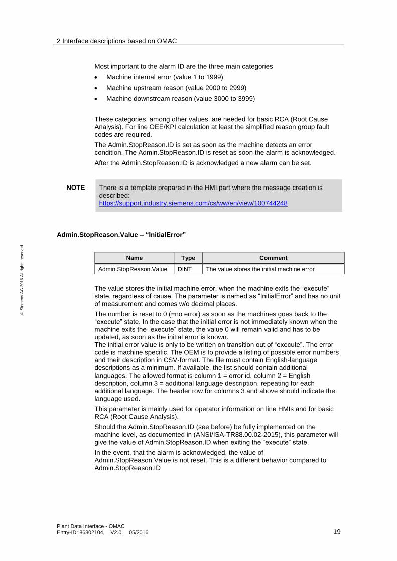
Most important to the alarm ID are the three main categories
Machine internal error (value 1 to 1999)
Machine upstream reason (value 2000 to 2999)
Machine downstream reason (value 3000 to 3999)
These categories, among other values, are needed for basic RCA (Root Cause Analysis). For line OEE/KPI calculation at least the simplified reason group fault codes are required.
The Admin.StopReason.ID is set as soon as the machine detects an error condition. The Admin.StopReason.ID is reset as soon the alarm is acknowledged.
After the Admin.StopReason.ID is acknowledged a new alarm can be set.
NOTE There is a template prepared in the HMI part where the message creation is described: https://support.industry.siemens.com/cs/ww/en/view/100744248
Admin.StopReason.Value – “InitialError”
The value stores the initial machine error, when the machine exits the “execute” state, regardless of cause. The parameter is named as “InitialError” and has no unit of measurement and comes w/o decimal places.
The number is reset to 0 (=no error) as soon as the machines goes back to the “execute” state. In the case that the initial error is not immediately known when the machine exits the “execute” state, the value 0 will remain valid and has to be updated, as soon as the initial error is known. The initial error value is only to be written on transition out of “execute”. The error code is machine specific. The OEM is to provide a listing of possible error numbers and their description in CSV-format. The file must contain English-language descriptions as a minimum. If available, the list should contain additional languages. The allowed format is column 1 = error id, column 2 = English description, column 3 = additional language description, repeating for each additional language. The header row for columns 3 and above should indicate the language used.
This parameter is mainly used for operator information on line HMIs and for basic RCA (Root Cause Analysis).
Should the Admin.StopReason.ID (see before) be fully implemented on the machine level, as documented in (ANSI/ISA-TR88.00.02-2015), this parameter will give the value of Admin.StopReason.ID when exiting the “execute” state.
In the event, that the alarm is acknowledged, the value of Admin.StopReason.Value is not reset. This is a different behavior compared to Admin.StopReason.ID
Name Type Comment
Admin.StopReason.Value DINT The value stores the initial machine error

2 Interface descriptions based on OMAC
Plant Data Interface - OMAC Entry-ID: 86302104, V2.0, 05/2016 20
S
iem
en
s A
G 2
01
6 A
ll ri
gh
ts r
ese
rve
d
2.2 PDI LCU
The LCU interface provides additional data for line control functionality, e.g. start/stop and set line speed. Machine state information is communicated upwards from machine/production level (OEM) up to the LCU and/or PSS. Control and command data such as machine speed and start/stop are transmitted downwards from upper level LCUs/PSSs to the machine/production level (OEM) (see also Fehler! Verweisquelle konnte nicht gefunden werden.). The data is used…
To provide operator information about machine speed and entry/exit buffer of single machines on line overview (HMI) screens, on line servers or at HMI clients in a control room
By the Line Control Unit to control the line, in terms of speed, buffer fill-levels and start/stop of machines
All data exchanged with the PDI LCU between line HMI (PSS) and the OEM PLC are tag based and can be polled by upper level systems at any time. Transfer of data between the Line Control Unit and OEM PLC should be performed block-wise to ensure data consistency.
Implementation of the PDI LCU is only required for systems implementing the Line Control Unit. The LCU is an additional package for plant wide automation that requires additional hardware and software components.

2 Interface descriptions based on OMAC
2.2 PDI LCU
Plant Data Interface - OMAC Entry-ID: 86302104, V2.0, 05/2016 21
Siemens AG 2016 All rights reserved
2.2.1 Interface description overview
Group Name
(Interface description)2
Type OMAC Man-datory
Description
Command Command.UnitMode DINT Unit mode is the selected target mode, requested by the line system for this machine
Command Command.UnitModeChangeRequest BOOL Is set when the unit mode change to the mode present in UnitName.Command.UnitMode should start.
Command Command.MachSpeed REAL Setpoint of machine speed in primary pieces/minute in the installed environment based on currently processed products
Command Command.CntrlCmd DINT State command to drive a state change in the Base State Model
Command Command.CmdChangeRequest BOOL Commands to proceed the state change as soon as it is set to 1
Command Command.Parameter0.Value BOOL RemoteControlActive indicates line controller is controlling the machine from external.
Status Status.PDIVersion String[10] PDI version info. “PDI V2.0.0” fix for this implementation
Status Status.ProjectVersion String[10] Project specific version
Status Status.StateRequested DINT As soon as the state change command is set (CntrlCmd = valid value and CmdChangeRequest= 1) the StateRequested value indicates the numerical value of target state
Status Status.StateChangeInProcess BOOL Indicates a state change initiated by CmdChangeRequest is in progress.
Status Status.Parameter4.Value DINT MachBufferEntry in % from 0 to 100 (optional)
Status Status.Parameter5.Value DINT MachBufferExit in % from 0 to 100 (optional)
Status Status.Parameter6.Value BOOL RemoteControlAllowed indicates if line controller / operator is allowed to control the machine from external command
2 For parameter naming for different systems (PLC, OPC, HMI-Tag,…) please see later table in this documentation

2 Interface descriptions based on OMAC
Plant Data Interface - OMAC Entry-ID: 86302104, V2.0, 05/2016 22
S
iem
en
s A
G 2
01
6 A
ll ri
gh
ts r
ese
rve
d
Status.Parameter(s) with index up to and including 69 are reserved for all covered values in PDI interfaces. PDI LCU is using index 4 to 6.
Status.Parameter(s) with index 70 or higher are reserved for OEM specific parameters.
In case machine specific or project specific parameters are required, the parameters can be delivered via the PDI PARA interface.
These two tags: “Command.UnitMode” and “Command.UnitModeChangeRequest” are added for future use and will not be used in this version.Interface description detailed information.
2.2.2 Interface description detailed information
Command.UnitMode
Name Type Comment
Command.UnitMode DINT The value describes the desired and unit modes
Data type: DINT
This value is predefined by the user/OEM, and stands for the desired unit modes of the machine. The UnitMode tag is a numerical representation of the commanded mode. There can be any number of unit modes, and for each unit mode there is an accompanying state model. The UnitMode according to ISA-88 (ANSI/ISA-TR88.00.02-2015).
Value Mode Description
0 Invalid The machine delivers an undefined mode.
1 Production* The machine executes relevant logic in production mode. The machine is producing product or able to produce product.
2 Maintenance This mode indicates that the machine is in maintenance mode. This mode would typically be used for faultfinding, machine trials or testing operational improvements.
3 Manual This mode indicates that the machine is in manual mode. This feature may be used for the commissioning of the individual drives, verifying the operation of synchronized drives, testing the drive as result of modifying parameters, etc.
4 – n User Defined A user defined mode can indicate a dedicated machine mode with its own state model.
Command.UnitModeChangeRequest
Name Type Comment
Command. UnitModeChangeRequest BOOL Request for changing the unit mode
When a unit mode request takes place a numerical value must be present in the “Command.UnitMode” tag to change the unit mode. Local processing and conditioning of the requested mode change is necessary in order to accept, reject, or condition the timing of the change request.
2 Interface descriptions based on OMAC
Plant Data Interface - OMAC Entry-ID: 86302104, V2.0, 05/2016 23
S
iem
en
s A
G 2
01
6 A
ll ri
gh
ts r
ese
rve
d
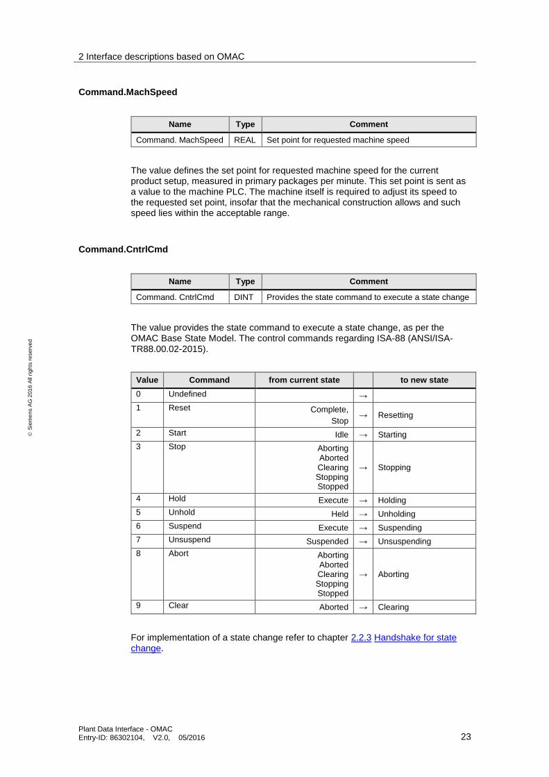
Command.MachSpeed
Name Type Comment
Command. MachSpeed REAL Set point for requested machine speed
The value defines the set point for requested machine speed for the current product setup, measured in primary packages per minute. This set point is sent as a value to the machine PLC. The machine itself is required to adjust its speed to the requested set point, insofar that the mechanical construction allows and such speed lies within the acceptable range.
Command.CntrlCmd
Name Type Comment
Command. CntrlCmd DINT Provides the state command to execute a state change
The value provides the state command to execute a state change, as per the OMAC Base State Model. The control commands regarding ISA-88 (ANSI/ISA-TR88.00.02-2015).
Value Command from current state to new state
0 Undefined →
1 Reset Complete,
Stop → Resetting
2 Start Idle → Starting
3 Stop Aborting Aborted Clearing Stopping Stopped
→ Stopping
4 Hold Execute → Holding
5 Unhold Held → Unholding
6 Suspend Execute → Suspending
7 Unsuspend Suspended → Unsuspending
8 Abort Aborting Aborted Clearing Stopping Stopped
→ Aborting
9 Clear Aborted → Clearing
For implementation of a state change refer to chapter 2.2.3 Handshake for state change.

2 Interface descriptions based on OMAC
Plant Data Interface - OMAC Entry-ID: 86302104, V2.0, 05/2016 24
S
iem
en
s A
G 2
01
6 A
ll ri
gh
ts r
ese
rve
d
Command.CmdChangeRequest
Name Type Comment
Command. CmdChangeRequest BOOL Initiate the machine to state change
This Boolean value commands the machine to initiate the state change, as indicated by CntrlCmd.
For implementation of a state change refer to chapter 2.2.3 Handshake for state change.
Command.Parameter0.Value – “RemoteControlActive”
Name Type Comment
Command. Parameter0.Value BOOL Remote control
The Parameter is named as “RemoteControlActive” and signals to the OEM-PLC that the LCU is actively controlling the machine regarding start/stop and machine speed. The command parameter is set by the LCU. When Command.Parameter[0].Value is 1, the machine should only assume local control in case an emergency condition raise up or the LCU causes the machine to run outside of specification. Command.Parameter[0].Value unequal 1 (typically 0) states that there is no LCU control active. This parameter is only relevant while the machine is in the “execute” state. In all other states or in any other production mode the machine is to assume control.
Status.PDIVersion
Name Type Comment
Status.PDIVersion String[10] The used PDI version
The PDIVersion parameter gives information about the version of the used plant data interface. For this implementation the string is fix: “PDI V2.0.0”.
Command.ProjectVersion
Name Type Comment
Status.ProjectVersion String[10] Project specific version of the interface
This data point provides a project specific version description of the interface implementation. Regarding the content there are no specifications determined.
2 Interface descriptions based on OMAC
Plant Data Interface - OMAC Entry-ID: 86302104, V2.0, 05/2016 25
S
iem
en
s A
G 2
01
6 A
ll ri
gh
ts r
ese
rve
d
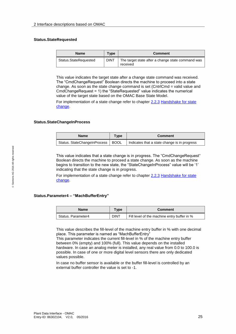
Status.StateRequested
Name Type Comment
Status.StateRequested DINT The target state after a change state command was received
This value indicates the target state after a change state command was received. The “CmdChangeRequest” Boolean directs the machine to proceed into a state change. As soon as the state change command is set (CntrlCmd = valid value and CmdChangeRequest = 1) the “StateRequested” value indicates the numerical value of the target state based on the OMAC Base State Model.
For implementation of a state change refer to chapter 2.2.3 Handshake for state change.
Status.StateChangeInProcess
Name Type Comment
Status. StateChangeInProcess BOOL Indicates that a state change is in progress
This value indicates that a state change is in progress. The “CmdChangeRequest“ Boolean directs the machine to proceed a state change. As soon as the machine begins to transition to the new state, the “StateChangeInProcess” value will be ‘1’ indicating that the state change is in progress.
For implementation of a state change refer to chapter 2.2.3 Handshake for state change.
Status.Parameter4 – “MachBufferEntry”
Name Type Comment
Status. Parameter4 DINT Fill level of the machine entry buffer in %
This value describes the fill-level of the machine entry buffer in % with one decimal place. This parameter is named as “MachBufferEntry” This parameter indicates the current fill-level in % of the machine entry buffer between 0% (empty) and 100% (full). This value depends on the installed hardware. In case an analog meter is installed, any real value from 0.0 to 100.0 is possible. In case of one or more digital level sensors there are only dedicated values possible.
In case no buffer sensor is available or the buffer fill-level is controlled by an external buffer controller the value is set to -1.

2 Interface descriptions based on OMAC
Plant Data Interface - OMAC Entry-ID: 86302104, V2.0, 05/2016 26
S
iem
en
s A
G 2
01
6 A
ll ri
gh
ts r
ese
rve
d
Status.Parameter5 – “MachBufferExit”
Name Type Comment
Status. Parameter5 DINT Level of the machine exit buffer in %
Data type: DINT
This value describes the level of the machine exit buffer in % with one decimal place. This parameter is named as “MachBufferExit”
This parameter indicates the current fill-level in % of the machine exit buffer between 0% (empty) and 100% (full). This value depends on the installed hardware. In case an analog meter is installed any real value from 0.0 to 100.0 is possible. In case of one or more digital level sensors there are only dedicated values possible.
In case no buffer sensor is available or the buffer fill-level is controlled by an external buffer controller the value is set to -1.
Status.Parameter6 – “RemoteControlAllowed”
Name Type Comment
Status. Parameter6 BOOL Indicates that the machine will accept a state change command
This value indicates that the machine will accept a state change command. This parameter is named as “RemoteControlAllowed”.
If the machine will accept a state change command from the LCU, the value attribute should be set to 1; otherwise the parameter should take on a value of 0.
Any value for the value attribute, other than 0 indicates that the machine accepts status change commands from the LCU.
2 Interface descriptions based on OMAC
Plant Data Interface - OMAC Entry-ID: 86302104, V2.0, 05/2016 27
S
iem
en
s A
G 2
01
6 A
ll ri
gh
ts r
ese
rve
d
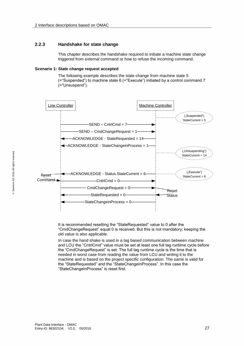
2.2.3 Handshake for state change
This chapter describes the handshake required to initiate a machine state change triggered from external command or how to refuse the incoming command.
Scenario 1: State change request accepted
The following example describes the state change from machine state 5 (=“Suspended”) to machine state 6 (=”Execute”) initiated by a control command 7 (=”Unsuspend”).
Line Controller Machine Controller
SEND – CntrlCmd = 7
SEND – CmdChangeRequest = 1
ACKNOWLEDGE - StateRequested = 14
ACKNOWLEDGE - StateChangeinProcess = 1
ACKNOWLEDGE - Status.StateCurrent = 6
CntrlCmd = 0
CmdChangeRequest = 0
StateRequested = 0
StateChangeinProcess = 0
Reset
Command
Reset
Status
(„Suspended“)
StateCurrent = 5
(„Execute“)
StateCurrent = 6
(„Unsuspending“)
StateCurrent = 14
It is recommended resetting the “StateRequested” value to 0 after the “CmdChangeRequest” equal 0 is received. But this is not mandatory; keeping the old value is also applicable.
In case the hand shake is used in a tag based communication between machine and LCU the “CntrlCmd” value must be set at least one full tag runtime cycle before the “CmdChangeRequest” is set. The full tag runtime cycle is the time that is needed in worst case from reading the value from LCU and writing it to the machine and is based on the project specific configuration. The same is valid for the “StateRequested” and the “StateChangeInProcess”. In this case the “StateChangeInProcess” is reset first.

2 Interface descriptions based on OMAC
Plant Data Interface - OMAC Entry-ID: 86302104, V2.0, 05/2016 28
S
iem
en
s A
G 2
01
6 A
ll ri
gh
ts r
ese
rve
d
At the beginning the following values are given:
Tag Value Description
Command.CntrlCmd 0 Undefined
Command.CmdChangeRequest 0 no request active
Status.StateCurrent 5 “Suspended”
Status.StateRequested 0 Undefined
Status.StateChangeInProcess 0 no requested state change active
The LCU sets the “Command.CntrlCmd” to 7 and “Command.CmdChangeRequest” to 1 indicating a state change should be processed by the machine.
At that time the following values are given:
Tag Value Description
Command.CntrlCmd 7 Unsuspend
Command.CmdChangeRequest 1 request active
Status.StateCurrent 5 “Suspended”
Status.StateRequested 0 Undefined
Status.StateChangeInProcess 0 no requested state change active
The machine controller set “Status.StateChangeInProcess” to 1 and “Status.StateRequested” to 14. The bit “Status.StateChangeInProcess” indicates
that a change in state is in progress following a state change request command.
At that time the following values are given:
Tag Value Description
Command.CntrlCmd 7 Unsuspend
Command.CmdChangeRequest 1 request active
Status.StateCurrent 5 “Suspended”
Status.StateRequested 14 Unsuspending
Status.StateChangeInProcess 1 requested state change active
As soon as the state “execute” is reached “Status.StateCurrent” is set to 6. This indicates that the requested command has been completed. The line controller resets “Command.CntrlCmd” and the “Command.CmdChangeRequest” to 0. “Command.CntrlCmd” equal 0, indicates undefined and “Command.CmdChangeRequest” equal 0 indicates no state change requested.
At that time the following values are given:
Tag Value Description
Command.CntrlCmd 0 Undefined
Command.CmdChangeRequest 0 No request active
Status.StateCurrent 6 “Execute”
Status.StateRequested 14 Unsuspending
Status.StateChangeInProcess 1 requested state change active
As soon as the “Command.CmdChangeRequest” is 0, the machine controller resets “Status.StateRequested” and “Status.StateChangeInProcess” to 0.
2 Interface descriptions based on OMAC
Plant Data Interface - OMAC Entry-ID: 86302104, V2.0, 05/2016 29
S
iem
en
s A
G 2
01
6 A
ll ri
gh
ts r
ese
rve
d
At the end the following values are given:
Tag Value Description
Command.CntrlCmd 0 Undefined
Command.CmdChangeRequest 0 No request active
Status.StateCurrent 6 “Execute”
Status.StateRequested 0 Undefined
Status.StateChangeInProcess 0 No requested state change active
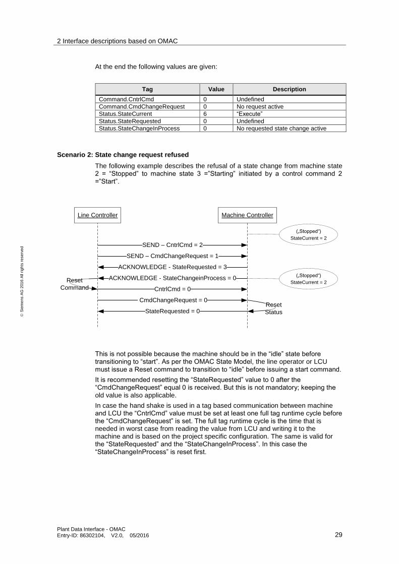
Scenario 2: State change request refused
The following example describes the refusal of a state change from machine state 2 = “Stopped” to machine state 3 =”Starting” initiated by a control command 2 =”Start”.
Line Controller Machine Controller
SEND – CntrlCmd = 2
SEND – CmdChangeRequest = 1
ACKNOWLEDGE - StateRequested = 3
ACKNOWLEDGE - StateChangeinProcess = 0
CntrlCmd = 0
CmdChangeRequest = 0
StateRequested = 0
Reset
Command
Reset
Status
(„Stopped“)
StateCurrent = 2
(„Stopped“)
StateCurrent = 2
This is not possible because the machine should be in the “idle” state before transitioning to “start”. As per the OMAC State Model, the line operator or LCU must issue a Reset command to transition to “idle” before issuing a start command.
It is recommended resetting the “StateRequested” value to 0 after the “CmdChangeRequest” equal 0 is received. But this is not mandatory; keeping the old value is also applicable.
In case the hand shake is used in a tag based communication between machine and LCU the “CntrlCmd” value must be set at least one full tag runtime cycle before the “CmdChangeRequest” is set. The full tag runtime cycle is the time that is needed in worst case from reading the value from LCU and writing it to the machine and is based on the project specific configuration. The same is valid for the “StateRequested” and the “StateChangeInProcess”. In this case the “StateChangeInProcess” is reset first.
2 Interface descriptions based on OMAC
Plant Data Interface - OMAC Entry-ID: 86302104, V2.0, 05/2016 30
S
iem
en
s A
G 2
01
6 A
ll ri
gh
ts r
ese
rve
d
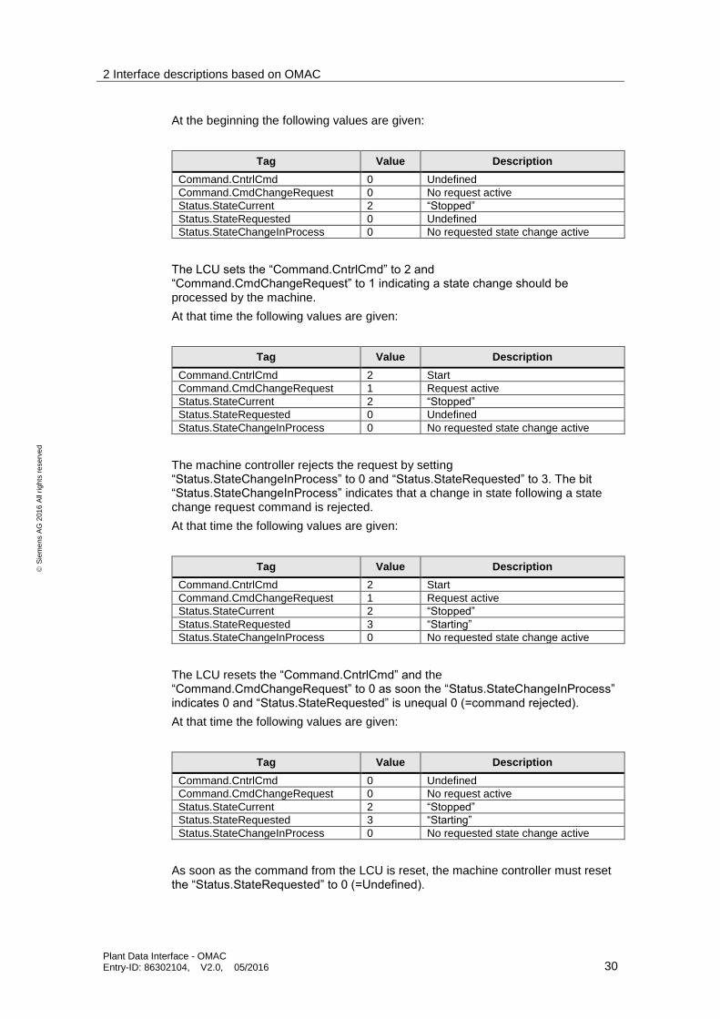
At the beginning the following values are given:
Tag Value Description
Command.CntrlCmd 0 Undefined
Command.CmdChangeRequest 0 No request active
Status.StateCurrent 2 “Stopped”
Status.StateRequested 0 Undefined
Status.StateChangeInProcess 0 No requested state change active
The LCU sets the “Command.CntrlCmd” to 2 and “Command.CmdChangeRequest” to 1 indicating a state change should be processed by the machine.
At that time the following values are given:
Tag Value Description
Command.CntrlCmd 2 Start
Command.CmdChangeRequest 1 Request active
Status.StateCurrent 2 “Stopped”
Status.StateRequested 0 Undefined
Status.StateChangeInProcess 0 No requested state change active
The machine controller rejects the request by setting “Status.StateChangeInProcess” to 0 and “Status.StateRequested” to 3. The bit “Status.StateChangeInProcess” indicates that a change in state following a state change request command is rejected.
At that time the following values are given:
Tag Value Description
Command.CntrlCmd 2 Start
Command.CmdChangeRequest 1 Request active
Status.StateCurrent 2 “Stopped”
Status.StateRequested 3 “Starting”
Status.StateChangeInProcess 0 No requested state change active
The LCU resets the “Command.CntrlCmd” and the “Command.CmdChangeRequest” to 0 as soon the “Status.StateChangeInProcess” indicates 0 and “Status.StateRequested” is unequal 0 (=command rejected).
At that time the following values are given:
Tag Value Description
Command.CntrlCmd 0 Undefined
Command.CmdChangeRequest 0 No request active
Status.StateCurrent 2 “Stopped”
Status.StateRequested 3 “Starting”
Status.StateChangeInProcess 0 No requested state change active
As soon as the command from the LCU is reset, the machine controller must reset the “Status.StateRequested” to 0 (=Undefined).
2 Interface descriptions based on OMAC
Plant Data Interface - OMAC Entry-ID: 86302104, V2.0, 05/2016 31
S
iem
en
s A
G 2
01
6 A
ll ri
gh
ts r
ese
rve
d
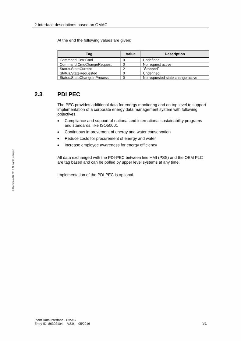
At the end the following values are given:
Tag Value Description
Command.CntrlCmd 0 Undefined
Command.CmdChangeRequest 0 No request active
Status.StateCurrent 2 “Stopped”
Status.StateRequested 0 Undefined
Status.StateChangeInProcess 0 No requested state change active
2.3 PDI PEC
The PEC provides additional data for energy monitoring and on top level to support implementation of a corporate energy data management system with following objectives.
Compliance and support of national and international sustainability programs and standards, like ISO50001
Continuous improvement of energy and water conservation
Reduce costs for procurement of energy and water
Increase employee awareness for energy efficiency
All data exchanged with the PDI-PEC between line HMI (PSS) and the OEM PLC are tag based and can be polled by upper level systems at any time.
Implementation of the PDI PEC is optional.
2 Interface descriptions based on OMAC
Plant Data Interface - OMAC Entry-ID: 86302104, V2.0, 05/2016 32
Siemens AG 2016 All rights reserved
2.3.1 Interface description overview
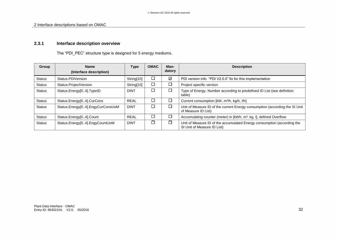
The “PDI_PEC” structure type is designed for 5 energy mediums.
Group Name
(Interface description)
Type OMAC Man-datory
Description
Status Status.PDIVersion String[10] PDI version info. “PDI V2.0.0” fix for this implementation
Status Status.ProjectVersion String[10] Project specific version
Status Status.Energy[0..4].TypeID DINT Type of Energy, Number according to predefined ID List (see definition table)
Status Status.Energy[0..4].CurCons REAL Current consumption [kW, m³/h, kg/h, l/h]
Status Status.Energy[0..4].EngyCurConsUoM DINT Unit of Measure ID of the current Energy consumption (according the SI Unit of Measure ID List)
Status Status.Energy[0..4].Count REAL Accumulating counter (meter) in [kWh, m³, kg, l], defined Overflow
Status Status.Energy[0..4].EngyCountUoM DINT Unit of Measure ID of the accumulated Energy consumption (according the SI Unit of Measure ID List)
2 Interface descriptions based on OMAC
Plant Data Interface - OMAC Entry-ID: 86302104, V2.0, 05/2016 33
S
iem
en
s A
G 2
01
6 A
ll ri
gh
ts r
ese
rve
d
2.3.2 Interface description detailed information
Status.PDIVersion
Name Type Comment
Status.PDIVersion String[10] Version of the used plant data interface
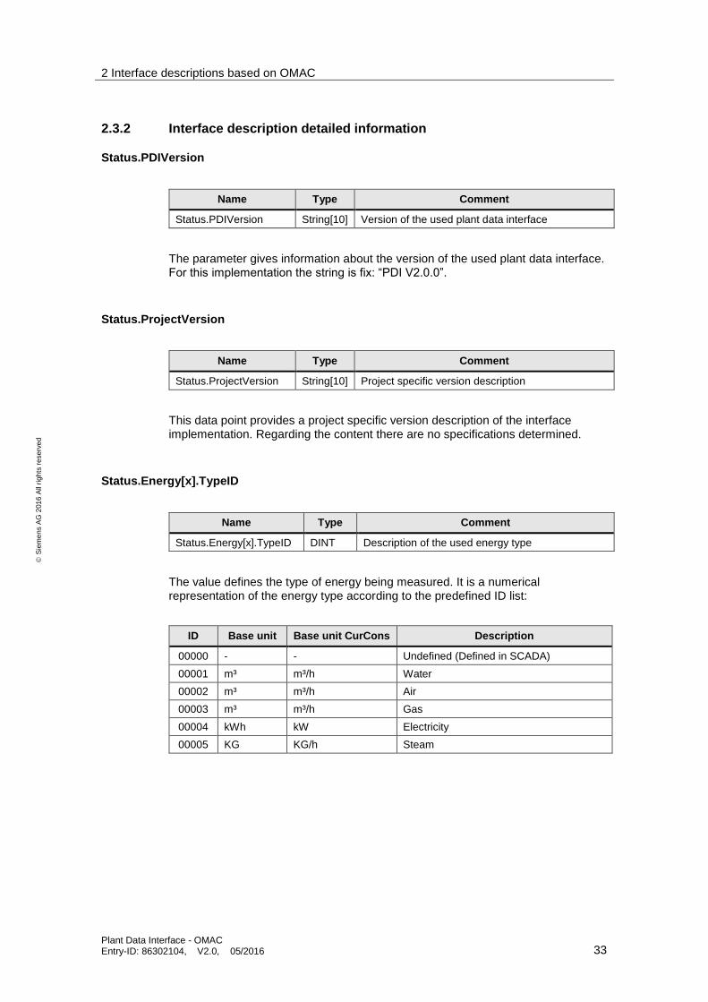
The parameter gives information about the version of the used plant data interface. For this implementation the string is fix: “PDI V2.0.0”.
Status.ProjectVersion
Name Type Comment
Status.ProjectVersion String[10] Project specific version description
This data point provides a project specific version description of the interface implementation. Regarding the content there are no specifications determined.
Status.Energy[x].TypeID
Name Type Comment
Status.Energy[x].TypeID DINT Description of the used energy type
The value defines the type of energy being measured. It is a numerical representation of the energy type according to the predefined ID list:
ID Base unit Base unit CurCons Description
00000 - - Undefined (Defined in SCADA)
00001 m³ m³/h Water
00002 m³ m³/h Air
00003 m³ m³/h Gas
00004 kWh kW Electricity
00005 KG KG/h Steam

2 Interface descriptions based on OMAC
Plant Data Interface - OMAC Entry-ID: 86302104, V2.0, 05/2016 34
S
iem
en
s A
G 2
01
6 A
ll ri
gh
ts r
ese
rve
d
Status.Energy[x].Count
Name Type Comment
Status.Energy[x].Count Real Accumulating counter of an energy meter
The value contains an accumulating counter of an energy meter.
The value starts counting as soon the meter counts. There is an overflow at 9.999.999,99 and the value starts again at 0. No decimal places are allowed. There is no reset in between.
This value has to be retained during PLC start/stop and PLC power off.
Status.Energy[x].EngyCountUoM
Name Type Comment
Status.Energy[x].EngyCountUoM DINT Unit of measure for the accumulating energy counter
The value defines the unit of measure for the accumulating energy counter. The DINT value of the tag is related to the unit in the corresponding ID list:
TIA@FuB UoM ID
TypeID Symbol Coversion Factor
Quantity Description
1082 1, 2, 3 m³ m³ Volume cubic metre
1084 1, 2, 3 l 10⁻³ m³ Volume Litre
1086 1, 2, 3 cm³ 10⁻⁶ m³ Volume cubic centimeter
1087 1, 2, 3 dm³ 10⁻³ m³ Volume cubic decimeter
1089 1, 2, 3 hl 10⁻¹ m³ Volume Hectoliter
1104 1, 2, 3 in³ 16,387 064 x 10⁻⁶ m³ Volume cubic inch
1106 1, 2, 3 yd³ 0,764 555 m³ Volume cubic yard
1107 1, 2, 3 gal (UK) 4,546 092 x 10⁻³ m³ Volume gallon (UK)
1108 1, 2, 3 gal (US) 3,785 412 x 10⁻³ m³ Volume gallon (US)
1127 1, 2, 3 fl oz (US) 2,957 353 x 10⁻⁵ m³ Volume fluid ounce (US)
3002 5 kg kg Mass Kilogram
3008 5 t 10³ kg Mass tonne (metric ton)
3014 5 lb 0,453 592 37 kg Mass Pound
3320 4 J J work, energy, potential energy Joule
3321 4 kJ 10³ J work, energy, potential energy Kilojoule
3326 4 MJ 10⁶ J work, energy, potential energy Megajoule
3330 4 W·h 3,6 x 10³ J work, energy, potential energy watt hour
3331 4 MW·h 3,6 x 10⁹ J work, energy, potential energy megawatt hour (1000 kW.h)
3332 4 kW·h 3,6 x 10⁶ J work, energy, potential energy kilowatt hour
2 Interface descriptions based on OMAC
Plant Data Interface - OMAC Entry-ID: 86302104, V2.0, 05/2016 35
S
iem
en
s A
G 2
01
6 A
ll ri
gh
ts r
ese
rve
d
Status.Energy[x].CurCons
Name Type Comment
Status.Energy[x].CurCons REAL Value of the current consumption
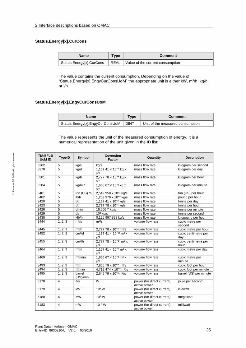
The value contains the current consumption. Depending on the value of “Status.Energy[x].EngyCurConsUoM” the appropriate unit is either kW, m³/h, kg/h or l/h.
Status.Energy[x].EngyCurConsUoM
Name Type Comment
Status.Energy[x].EngyCurConsUoM DINT Unit of the measured consumption
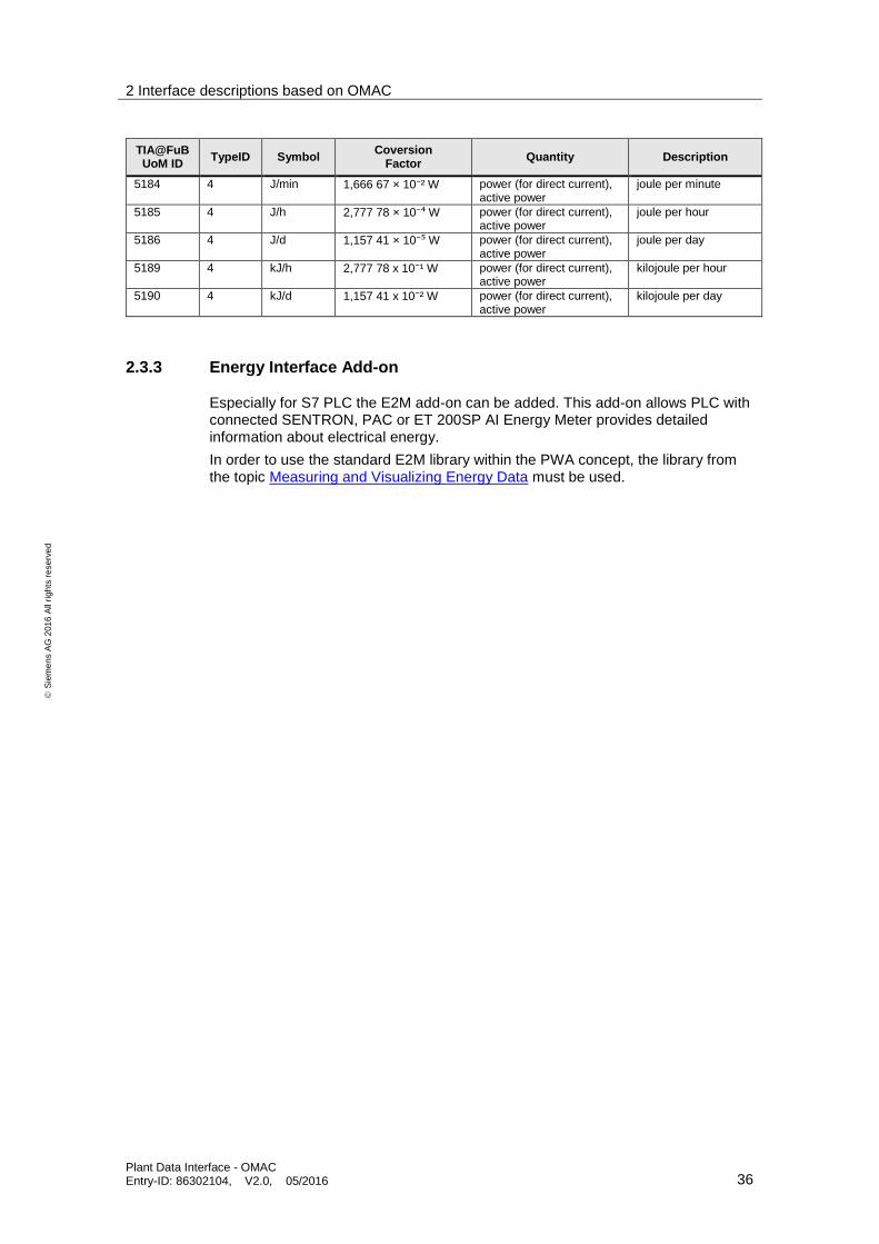
The value represents the unit of the measured consumption of energy. It is a numerical representation of the unit given in the ID list:
TIA@FuB UoM ID
TypeID Symbol Coversion
Factor Quantity Description
3362 5 kg/s kg/s mass flow rate kilogram per second
3378 5 kg/d 1,157 41 × 10⁻⁵ kg x s⁻¹
mass flow rate kilogram per day
3381 5 kg/h 2,777 78 × 10⁻⁴ kg x s⁻¹
mass flow rate kilogram per hour
3384 5 kg/min 1,666 67 × 10⁻² kg x s⁻¹
mass flow rate kilogram per minute
3401 5 ton (US) /h 2,519 958 x 10⁻¹ kg/s mass flow rate ton (US) per hour
3402 5 lb/h 1,259 979 x 10⁻⁴ kg/s mass flow rate pound per hour
3420 5 t/d 1,157 41 x 10⁻² kg/s mass flow rate tonne per day
3423 5 t/h 2,777 78 x 10⁻¹ kg/s mass flow rate tonne per hour
3426 5 t/min 16,666 7 kg/s mass flow rate tonne per minute
3429 5 t/s 10³ kg/s mass flow rate tonne per second
3438 5 klb/h 0,125 997 889 kg/s mass flow rate kilopound per hour
3444 1, 2, 3 m³/s m³/s volume flow rate cubic metre per second
3445 1, 2, 3 m³/h 2,777 78 x 10⁻⁴ m³/s volume flow rate cubic metre per hour
3452 1, 2, 3 cm³/d 1,157 41 × 10⁻¹¹ m³ x s⁻¹
volume flow rate cubic centimetre per day
3455 1, 2, 3 cm³/h 2,777 78 × 10⁻¹⁰ m³ x s⁻¹
volume flow rate cubic centimetre per hour
3464 1, 2, 3 m³/d 1,157 41 × 10⁻⁵ m³ x s⁻¹
volume flow rate cubic metre per day
3469 1, 2, 3 m³/min 1,666 67 × 10⁻² m³ x s⁻¹
volume flow rate cubic metre per minute
3493 1, 2, 3 ft³/h 7,865 79 x 10⁻⁶ m³/s volume flow rate cubic foot per hour
3494 1, 2, 3 ft³/min 4,719 474 x 10⁻⁴ m³/s volume flow rate cubic foot per minute
3495 1, 2, 3 barrel (US)/min
2,649 79 x 10⁻³ m³/s volume flow rate barrel (US) per minute
5178 4 J/s W power (for direct current), active power
joule per second
5179 4 kW 10³ W power (for direct current), active power
kilowatt
5180 4 MW 10⁶ W power (for direct current), active power
megawatt
5183 4 mW 10⁻³ W power (for direct current), active power
milliwatt
2 Interface descriptions based on OMAC
Plant Data Interface - OMAC Entry-ID: 86302104, V2.0, 05/2016 36
S
iem
en
s A
G 2
01
6 A
ll ri
gh
ts r
ese
rve
d
TIA@FuB UoM ID
TypeID Symbol Coversion
Factor Quantity Description
5184 4 J/min 1,666 67 × 10⁻² W power (for direct current), active power
joule per minute
5185 4 J/h 2,777 78 × 10⁻⁴ W power (for direct current), active power
joule per hour
5186 4 J/d 1,157 41 × 10⁻⁵ W power (for direct current), active power
joule per day
5189 4 kJ/h 2,777 78 x 10⁻¹ W power (for direct current), active power
kilojoule per hour
5190 4 kJ/d 1,157 41 x 10⁻² W power (for direct current), active power
kilojoule per day
2.3.3 Energy Interface Add-on
Especially for S7 PLC the E2M add-on can be added. This add-on allows PLC with connected SENTRON, PAC or ET 200SP AI Energy Meter provides detailed information about electrical energy.
In order to use the standard E2M library within the PWA concept, the library from the topic Measuring and Visualizing Energy Data must be used.
2 Interface descriptions based on OMAC
Plant Data Interface - OMAC Entry-ID: 86302104, V2.0, 05/2016 37
S
iem
en
s A
G 2
01
6 A
ll ri
gh
ts r
ese
rve
d
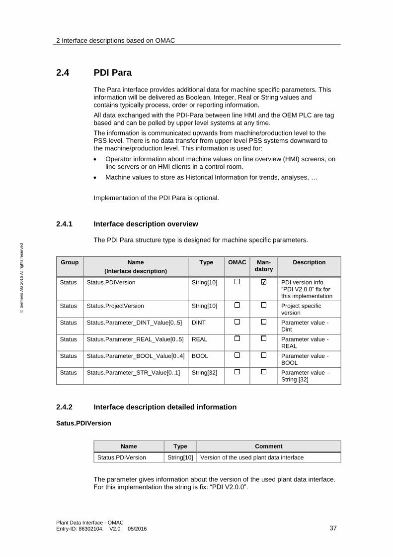
2.4 PDI Para
The Para interface provides additional data for machine specific parameters. This information will be delivered as Boolean, Integer, Real or String values and contains typically process, order or reporting information.
All data exchanged with the PDI-Para between line HMI and the OEM PLC are tag based and can be polled by upper level systems at any time.
The information is communicated upwards from machine/production level to the PSS level. There is no data transfer from upper level PSS systems downward to the machine/production level. This information is used for:
Operator information about machine values on line overview (HMI) screens, on line servers or on HMI clients in a control room.
Machine values to store as Historical Information for trends, analyses, …
Implementation of the PDI Para is optional.
2.4.1 Interface description overview
The PDI Para structure type is designed for machine specific parameters.
Group Name
(Interface description)
Type OMAC Man-datory
Description
Status Status.PDIVersion String[10] PDI version info. “PDI V2.0.0” fix for this implementation
Status Status.ProjectVersion String[10] Project specific version
Status Status.Parameter_DINT_Value[0..5] DINT Parameter value - Dint
Status Status.Parameter_REAL_Value[0..5] REAL Parameter value - REAL
Status Status.Parameter_BOOL_Value[0..4] BOOL Parameter value - BOOL
Status Status.Parameter_STR_Value[0..1] String[32] Parameter value – String [32]
2.4.2 Interface description detailed information
Satus.PDIVersion
Name Type Comment
Status.PDIVersion String[10] Version of the used plant data interface
The parameter gives information about the version of the used plant data interface. For this implementation the string is fix: “PDI V2.0.0”.
2 Interface descriptions based on OMAC
Plant Data Interface - OMAC Entry-ID: 86302104, V2.0, 05/2016 38
S
iem
en
s A
G 2
01
6 A
ll ri
gh
ts r
ese
rve
d
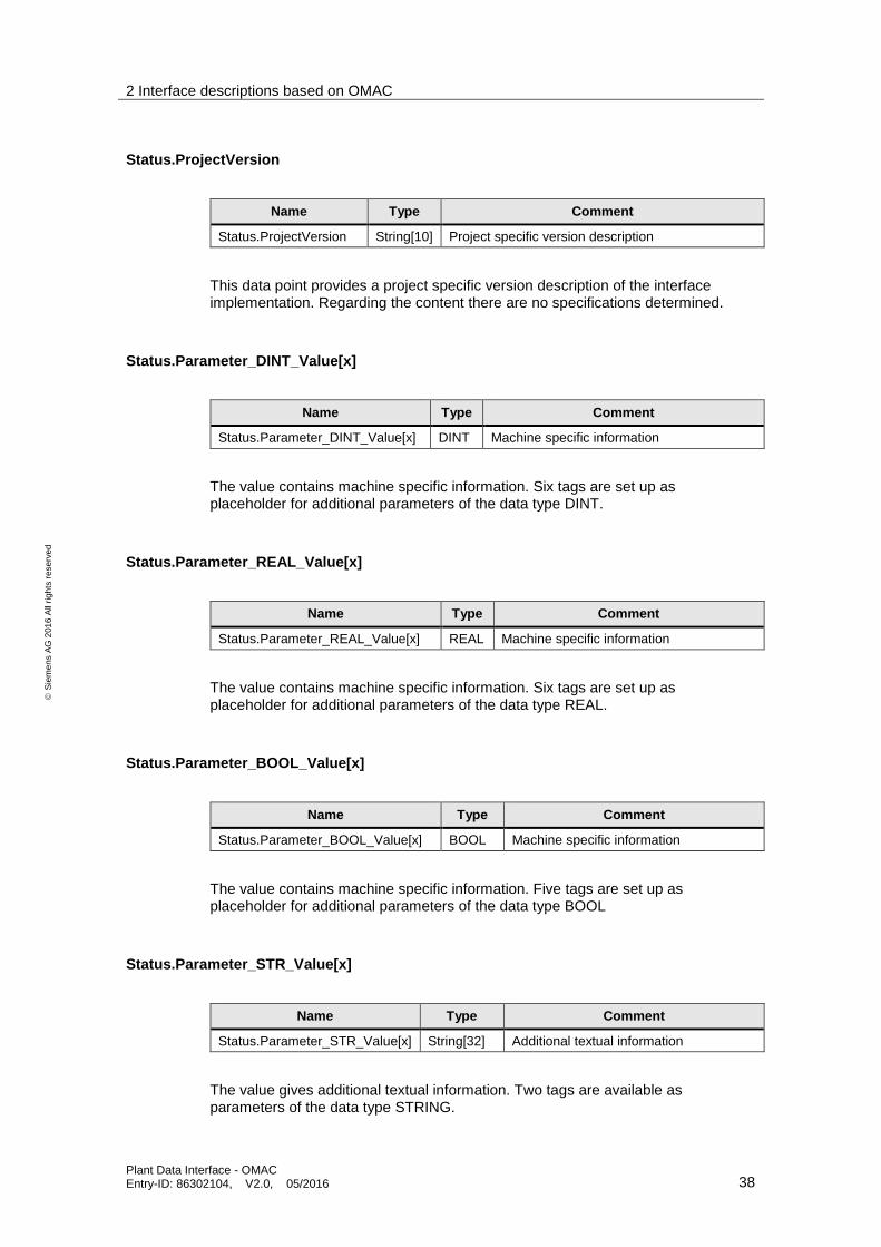
Status.ProjectVersion
Name Type Comment
Status.ProjectVersion String[10] Project specific version description
This data point provides a project specific version description of the interface implementation. Regarding the content there are no specifications determined.
Status.Parameter_DINT_Value[x]
Name Type Comment
Status.Parameter_DINT_Value[x] DINT Machine specific information
The value contains machine specific information. Six tags are set up as placeholder for additional parameters of the data type DINT.
Status.Parameter_REAL_Value[x]
Name Type Comment
Status.Parameter_REAL_Value[x] REAL Machine specific information
The value contains machine specific information. Six tags are set up as placeholder for additional parameters of the data type REAL.
Status.Parameter_BOOL_Value[x]
Name Type Comment
Status.Parameter_BOOL_Value[x] BOOL Machine specific information
The value contains machine specific information. Five tags are set up as placeholder for additional parameters of the data type BOOL
Status.Parameter_STR_Value[x]
Name Type Comment
Status.Parameter_STR_Value[x] String[32] Additional textual information
The value gives additional textual information. Two tags are available as parameters of the data type STRING.
3 General PDI Information
Plant Data Interface - OMAC Entry-ID: 86302104, V2.0, 05/2016 39
S
iem
en
s A
G 2
01
6 A
ll ri
gh
ts r
ese
rve
d
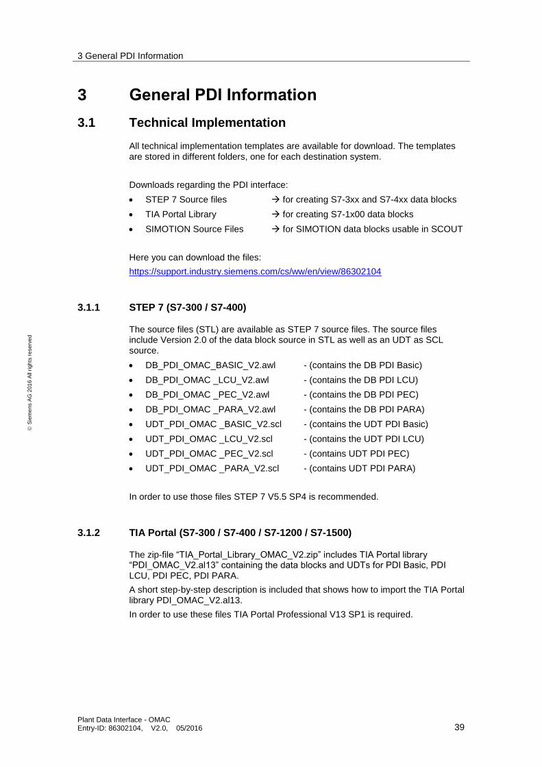
3 General PDI Information
3.1 Technical Implementation
All technical implementation templates are available for download. The templates are stored in different folders, one for each destination system.
Downloads regarding the PDI interface:
STEP 7 Source files for creating S7-3xx and S7-4xx data blocks
TIA Portal Library for creating S7-1x00 data blocks
SIMOTION Source Files for SIMOTION data blocks usable in SCOUT
Here you can download the files:
https://support.industry.siemens.com/cs/ww/en/view/86302104
3.1.1 STEP 7 (S7-300 / S7-400)
The source files (STL) are available as STEP 7 source files. The source files include Version 2.0 of the data block source in STL as well as an UDT as SCL source.
DB_PDI_OMAC_BASIC_V2.awl - (contains the DB PDI Basic)
DB_PDI_OMAC _LCU_V2.awl - (contains the DB PDI LCU)
DB_PDI_OMAC _PEC_V2.awl - (contains the DB PDI PEC)
DB_PDI_OMAC _PARA_V2.awl - (contains the DB PDI PARA)
UDT_PDI_OMAC _BASIC_V2.scl - (contains the UDT PDI Basic)
UDT_PDI_OMAC _LCU_V2.scl - (contains the UDT PDI LCU)
UDT_PDI_OMAC _PEC_V2.scl - (contains UDT PDI PEC)
UDT_PDI_OMAC _PARA_V2.scl - (contains UDT PDI PARA)
In order to use those files STEP 7 V5.5 SP4 is recommended.
3.1.2 TIA Portal (S7-300 / S7-400 / S7-1200 / S7-1500)
The zip-file “TIA_Portal_Library_OMAC_V2.zip” includes TIA Portal library “PDI_OMAC_V2.al13” containing the data blocks and UDTs for PDI Basic, PDI LCU, PDI PEC, PDI PARA.
A short step-by-step description is included that shows how to import the TIA Portal library PDI_OMAC_V2.al13.
In order to use these files TIA Portal Professional V13 SP1 is required.

3 General PDI Information
Plant Data Interface - OMAC Entry-ID: 86302104, V2.0, 05/2016 40
S
iem
en
s A
G 2
01
6 A
ll ri
gh
ts r
ese
rve
d
3.1.3 SIMOTION SCOUT
The SIMOTION PDI interfaces are available as xml files, which include the ST units with the data structures for PDI_BASIC, PDI_LCU, PDI_PEC and PDI_PARA. Depending on project requirements the corresponding PDI can be imported respectively.
In order to use this files SCOUT 4.4 or higher is required.
3.2 State description
For more details please see original source /2/ ISA-TR88.00.02.
The picture shows the complete state model with all 17 states:
RESETTING
IDLE STARTING
UNSUS-
PENDING
UN-
HOLDINGHELD
SUS-
PENDED
COMPLETECOM-
PLETING
SUS-
PENDING
HOLDING
dualactingwait
STOPPED STOPPING CLEARING ABORTED ABORTING
EXECUTE
Un-Hold
Un-Suspend
Suspend
Hold
Start
Reset
Reset
Clear
SCSC
SC
SC
SC
SC
SC
SC SC
SC
Stop Abort
State Types:
STOPPED (State type: wait)
The machine is powered and stationary after completing the STOPPING state. All communications with other systems are functioning (if applicable). A reset command will cause an exit from STOPPED to the RESETTING state.
STARTING (State type: acting)
This state provides the steps needed to start the machine and is a result of a starting type command (local or remote). Following this command the machine will begin to Execute.
3 General PDI Information
Plant Data Interface - OMAC Entry-ID: 86302104, V2.0, 05/2016 41
S
iem
en
s A
G 2
01
6 A
ll ri
gh
ts r
ese
rve
d
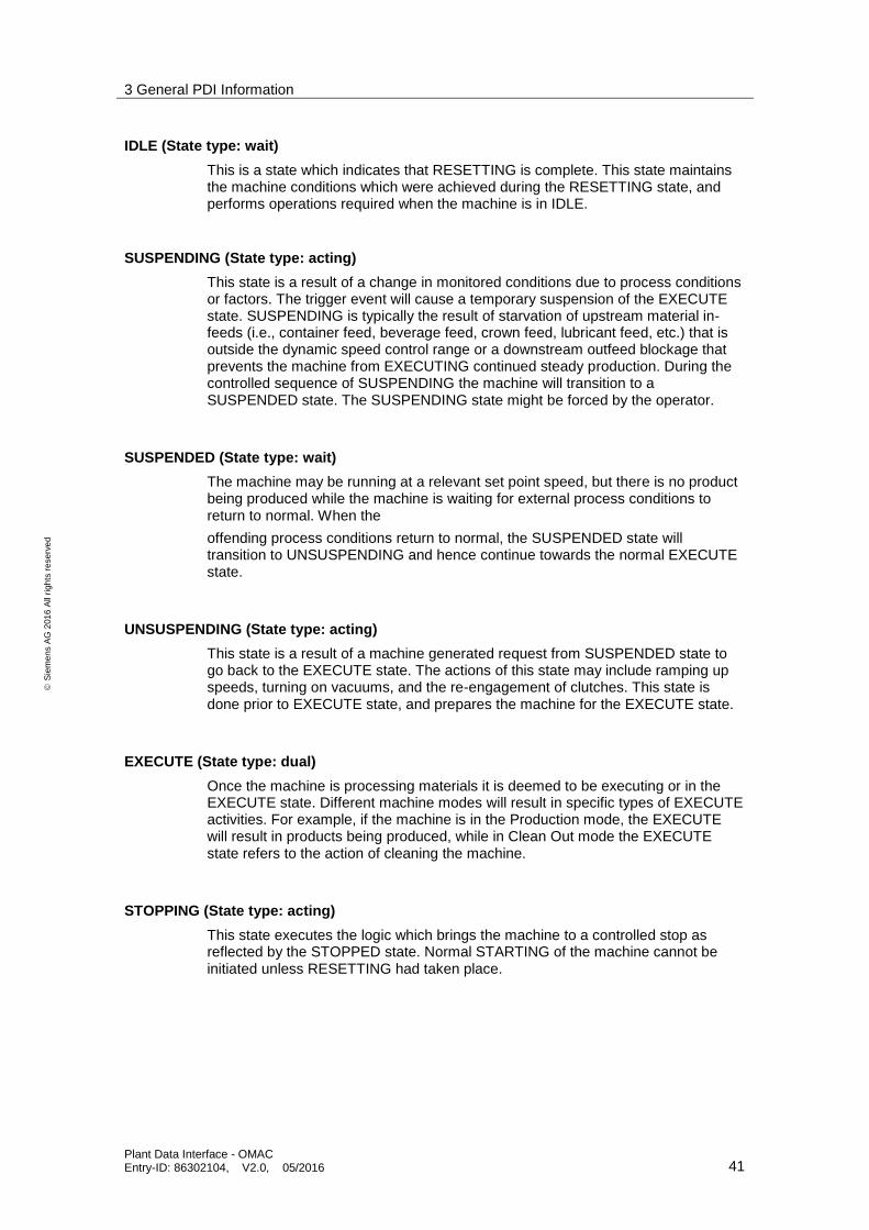
IDLE (State type: wait)
This is a state which indicates that RESETTING is complete. This state maintains the machine conditions which were achieved during the RESETTING state, and performs operations required when the machine is in IDLE.
SUSPENDING (State type: acting)
This state is a result of a change in monitored conditions due to process conditions or factors. The trigger event will cause a temporary suspension of the EXECUTE state. SUSPENDING is typically the result of starvation of upstream material in-feeds (i.e., container feed, beverage feed, crown feed, lubricant feed, etc.) that is outside the dynamic speed control range or a downstream outfeed blockage that prevents the machine from EXECUTING continued steady production. During the controlled sequence of SUSPENDING the machine will transition to a SUSPENDED state. The SUSPENDING state might be forced by the operator.
SUSPENDED (State type: wait)
The machine may be running at a relevant set point speed, but there is no product being produced while the machine is waiting for external process conditions to return to normal. When the
offending process conditions return to normal, the SUSPENDED state will transition to UNSUSPENDING and hence continue towards the normal EXECUTE state.
UNSUSPENDING (State type: acting)
This state is a result of a machine generated request from SUSPENDED state to go back to the EXECUTE state. The actions of this state may include ramping up speeds, turning on vacuums, and the re-engagement of clutches. This state is done prior to EXECUTE state, and prepares the machine for the EXECUTE state.
EXECUTE (State type: dual)
Once the machine is processing materials it is deemed to be executing or in the EXECUTE state. Different machine modes will result in specific types of EXECUTE activities. For example, if the machine is in the Production mode, the EXECUTE will result in products being produced, while in Clean Out mode the EXECUTE state refers to the action of cleaning the machine.
STOPPING (State type: acting)
This state executes the logic which brings the machine to a controlled stop as reflected by the STOPPED state. Normal STARTING of the machine cannot be initiated unless RESETTING had taken place.
3 General PDI Information
Plant Data Interface - OMAC Entry-ID: 86302104, V2.0, 05/2016 42
S
iem
en
s A
G 2
01
6 A
ll ri
gh
ts r
ese
rve
d
ABORTING (State type: acting)
The ABORTED state can be entered at any time in response to the abort command or on the occurrence of a machine fault. The aborting logic will bring the machine to a rapid safe stop.
Operation of the emergency stop will cause the machine to be tripped by its safety system. It will also provide a signal to initiate the ABORTING State.
ABORTED (State type: wait)
This state maintains machine status information relevant to the Abort condition. The machine can only exit the ABORTED state after an explicit clear command, subsequently to manual intervention to correct and reset the detected machine faults.
HOLDING (State type: acting)
When the machine is in the EXECUTE state, the hold command can be used to start HOLDING logic which brings the machine to a controlled stop or to a state which represents HELD for the particular unit control mode. A machine can go into this state either when an internal equipment fault is automatically detected or by an operator command. The hold command offers the operator a safe way to intervene manually in the process and restarting execution when conditions are safe.
HELD (State type: wait)
The HELD state holds the machine's operation while material blockages are cleared, or to stop throughput while a downstream problem is resolved, or enable the safe correction of an equipment fault before the production may be resumed.
UNHOLDING (State type: acting)
The UNHOLDING state is a response to an Operator command to resume the EXECUTE state. Issuing the un-hold command will retrieve the saved set-points and return the status.
Conditions to prepare the machine to re-enter the normal EXECUTE state.
NOTE An operator UNHOLD command is always required and UNHOLDING can never be initiated automatically.
COMPLETING (State type: acting)
This state is an automatic response from the EXECUTE state. Normal operation has run to completion (i.e., processing of material at the infeed will stop).
COMPLETE (State type: wait)
The machine has finished the COMPLETING state and is now waiting for a reset command before transitioning to the RESETTING state.

3 General PDI Information
Plant Data Interface - OMAC Entry-ID: 86302104, V2.0, 05/2016 43
S
iem
en
s A
G 2
01
6 A
ll ri
gh
ts r
ese
rve
d
RESETTING (State type: acting)
This state is the result of a RESET command from the STOPPED or complete state. RESETTING will typically cause a machine to sound a horn and place the machine in a state where components are energized awaiting a start command.
CLEARING (State type: acting)
Initiated by a state command to clear faults that may have occurred when ABORTING, and are present in the ABORTED state before proceeding to a STOPPED state.
3.3 Cross naming reference (system wide)
The following table shows the naming conventions in regards to the different standards and the implemented naming within the various components of the SIEMENS plant wide automation architecture.
The column “Name based on OMAC” gives the identifier as defined by the OMAC standard. To make comparison between the Weihenstephan Standards and the OMAC standard easier, the column “Name based on Weihenstephan” is provided as information. In all system packages needed for a plant wide automation where the implementation of both OMAC and Weihenstephan standards requires abstract naming conventions, neutral naming is useful. Therefore, the use of the abstract names as provided in column “Naming on WinCC” is highly recommended.
Name based on OMAC Name based on Weihenstephan
Name in WinCC
Status.PDIVersion SIE_Ver_Basic PDI_Version
Status.ProjectVersion SIE_Ver_Proj_Basic Project_Version
Status.UnitModeCurrent WS_Cur_Prog Current_Mode
Status.StateCurrent WS_Cur_State Current_State
Status.MachSpeed WS_Set_Mach_Spd Setpoint_Speed
Status.CurMachSpeed WS_Cur_Mach_Spd Current_Speed
Status.EquipmentInterlock.Blocked - Equipment_Interlock_Blocked
Status.EquipmentInterlock.Starved - Equipment_Interlock_Starved
Status.Parameter0.Value SIE_Mach_Cum_Time Power_Up_Time
Status.Parameter1.Value WS_Cons_Electricity Consumed_Energy
Status.Parameter2.Value WS_Prod_Ratio Product_Ratio
Status.Parameter3.Value SIE_Prod_Ratio_Typ Product_Ratio_Type
Status.LightStack SIE_Light_Stack Light_Stack
Admin.ProdProcessedCount[0].Count SIE_Tot_Packages All_Processed_Counter_Resettable
Admin.ProdProcessedCount[0].AccCount WS_Tot_Packages All_Processed_Counter_Non_Resettable
Admin.ProdDefectiveCount[0].Count SIE_Bad_Packages Defect_Counter_Resettable
Admin.ProdDefectiveCount[0].AccCount WS_Bad_Packages Defect_Counter_Non_Resettable
Admin.MachDesignSpeed WS_Mach_Design_Spd Design_Speed
Admin.StopReason.ID SIE_Not_Of_Fail_Group First_Fault
Admin.StopReason.Value WS_Not_Of_Fail_Code OEM_First_Fault
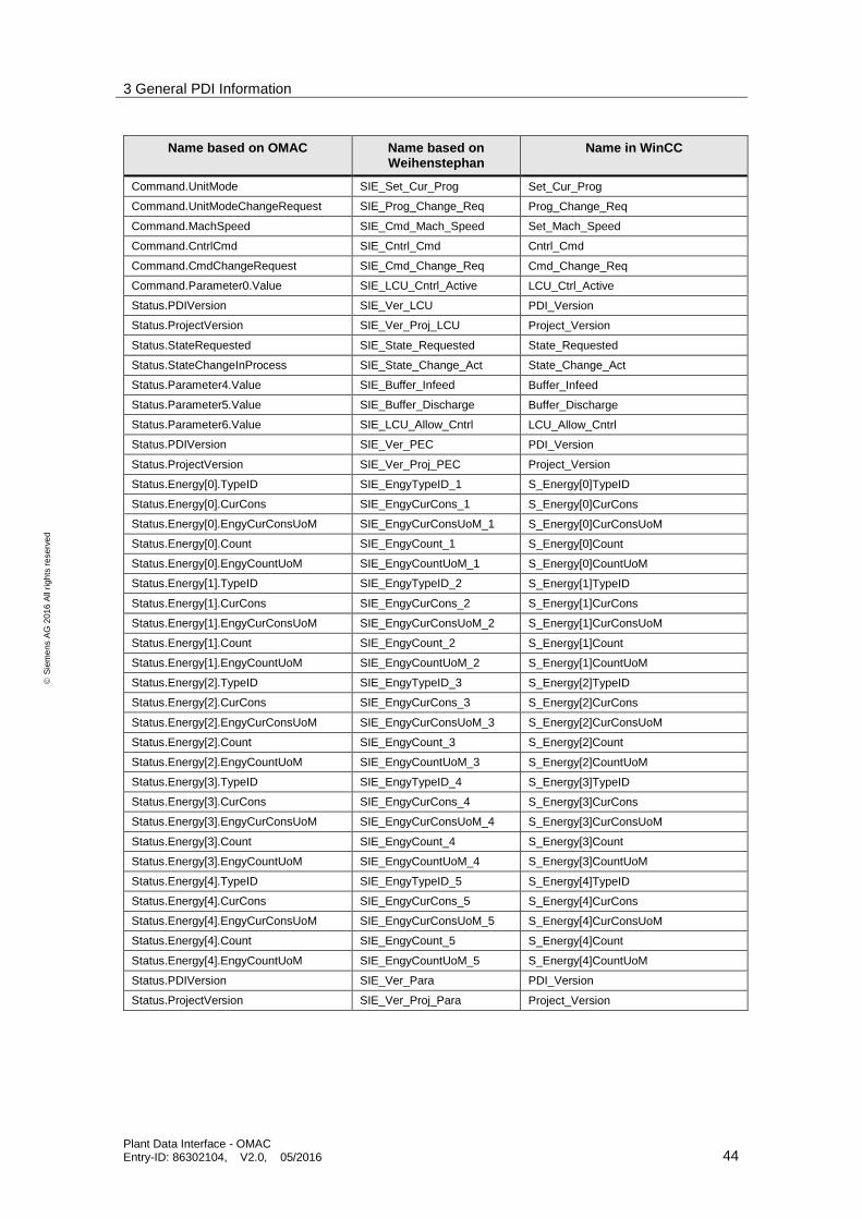
3 General PDI Information
Plant Data Interface - OMAC Entry-ID: 86302104, V2.0, 05/2016 44
S
iem
en
s A
G 2
01
6 A
ll ri
gh
ts r
ese
rve
d
Name based on OMAC Name based on Weihenstephan
Name in WinCC
Command.UnitMode SIE_Set_Cur_Prog Set_Cur_Prog
Command.UnitModeChangeRequest SIE_Prog_Change_Req Prog_Change_Req
Command.MachSpeed SIE_Cmd_Mach_Speed Set_Mach_Speed
Command.CntrlCmd SIE_Cntrl_Cmd Cntrl_Cmd
Command.CmdChangeRequest SIE_Cmd_Change_Req Cmd_Change_Req
Command.Parameter0.Value SIE_LCU_Cntrl_Active LCU_Ctrl_Active
Status.PDIVersion SIE_Ver_LCU PDI_Version
Status.ProjectVersion SIE_Ver_Proj_LCU Project_Version
Status.StateRequested SIE_State_Requested State_Requested
Status.StateChangeInProcess SIE_State_Change_Act State_Change_Act
Status.Parameter4.Value SIE_Buffer_Infeed Buffer_Infeed
Status.Parameter5.Value SIE_Buffer_Discharge Buffer_Discharge
Status.Parameter6.Value SIE_LCU_Allow_Cntrl LCU_Allow_Cntrl
Status.PDIVersion SIE_Ver_PEC PDI_Version
Status.ProjectVersion SIE_Ver_Proj_PEC Project_Version
Status.Energy[0].TypeID SIE_EngyTypeID_1 S_Energy[0]TypeID
Status.Energy[0].CurCons SIE_EngyCurCons_1 S_Energy[0]CurCons
Status.Energy[0].EngyCurConsUoM SIE_EngyCurConsUoM_1 S_Energy[0]CurConsUoM
Status.Energy[0].Count SIE_EngyCount_1 S_Energy[0]Count
Status.Energy[0].EngyCountUoM SIE_EngyCountUoM_1 S_Energy[0]CountUoM
Status.Energy[1].TypeID SIE_EngyTypeID_2 S_Energy[1]TypeID
Status.Energy[1].CurCons SIE_EngyCurCons_2 S_Energy[1]CurCons
Status.Energy[1].EngyCurConsUoM SIE_EngyCurConsUoM_2 S_Energy[1]CurConsUoM
Status.Energy[1].Count SIE_EngyCount_2 S_Energy[1]Count
Status.Energy[1].EngyCountUoM SIE_EngyCountUoM_2 S_Energy[1]CountUoM
Status.Energy[2].TypeID SIE_EngyTypeID_3 S_Energy[2]TypeID
Status.Energy[2].CurCons SIE_EngyCurCons_3 S_Energy[2]CurCons
Status.Energy[2].EngyCurConsUoM SIE_EngyCurConsUoM_3 S_Energy[2]CurConsUoM
Status.Energy[2].Count SIE_EngyCount_3 S_Energy[2]Count
Status.Energy[2].EngyCountUoM SIE_EngyCountUoM_3 S_Energy[2]CountUoM
Status.Energy[3].TypeID SIE_EngyTypeID_4 S_Energy[3]TypeID
Status.Energy[3].CurCons SIE_EngyCurCons_4 S_Energy[3]CurCons
Status.Energy[3].EngyCurConsUoM SIE_EngyCurConsUoM_4 S_Energy[3]CurConsUoM
Status.Energy[3].Count SIE_EngyCount_4 S_Energy[3]Count
Status.Energy[3].EngyCountUoM SIE_EngyCountUoM_4 S_Energy[3]CountUoM
Status.Energy[4].TypeID SIE_EngyTypeID_5 S_Energy[4]TypeID
Status.Energy[4].CurCons SIE_EngyCurCons_5 S_Energy[4]CurCons
Status.Energy[4].EngyCurConsUoM SIE_EngyCurConsUoM_5 S_Energy[4]CurConsUoM
Status.Energy[4].Count SIE_EngyCount_5 S_Energy[4]Count
Status.Energy[4].EngyCountUoM SIE_EngyCountUoM_5 S_Energy[4]CountUoM
Status.PDIVersion SIE_Ver_Para PDI_Version
Status.ProjectVersion SIE_Ver_Proj_Para Project_Version
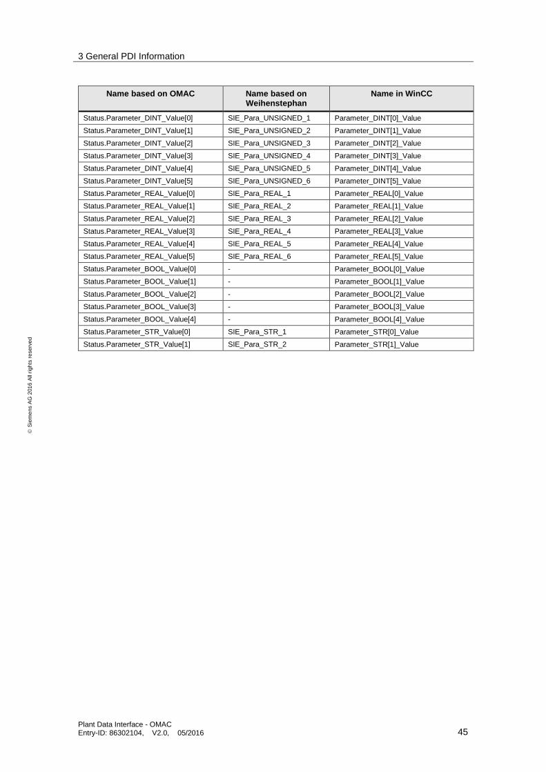
3 General PDI Information
Plant Data Interface - OMAC Entry-ID: 86302104, V2.0, 05/2016 45
S
iem
en
s A
G 2
01
6 A
ll ri
gh
ts r
ese
rve
d
Name based on OMAC Name based on Weihenstephan
Name in WinCC
Status.Parameter_DINT_Value[0] SIE_Para_UNSIGNED_1 Parameter_DINT[0]_Value
Status.Parameter_DINT_Value[1] SIE_Para_UNSIGNED_2 Parameter_DINT[1]_Value
Status.Parameter_DINT_Value[2] SIE_Para_UNSIGNED_3 Parameter_DINT[2]_Value
Status.Parameter_DINT_Value[3] SIE_Para_UNSIGNED_4 Parameter_DINT[3]_Value
Status.Parameter_DINT_Value[4] SIE_Para_UNSIGNED_5 Parameter_DINT[4]_Value
Status.Parameter_DINT_Value[5] SIE_Para_UNSIGNED_6 Parameter_DINT[5]_Value
Status.Parameter_REAL_Value[0] SIE_Para_REAL_1 Parameter_REAL[0]_Value
Status.Parameter_REAL_Value[1] SIE_Para_REAL_2 Parameter_REAL[1]_Value
Status.Parameter_REAL_Value[2] SIE_Para_REAL_3 Parameter_REAL[2]_Value
Status.Parameter_REAL_Value[3] SIE_Para_REAL_4 Parameter_REAL[3]_Value
Status.Parameter_REAL_Value[4] SIE_Para_REAL_5 Parameter_REAL[4]_Value
Status.Parameter_REAL_Value[5] SIE_Para_REAL_6 Parameter_REAL[5]_Value
Status.Parameter_BOOL_Value[0] - Parameter_BOOL[0]_Value
Status.Parameter_BOOL_Value[1] - Parameter_BOOL[1]_Value
Status.Parameter_BOOL_Value[2] - Parameter_BOOL[2]_Value
Status.Parameter_BOOL_Value[3] - Parameter_BOOL[3]_Value
Status.Parameter_BOOL_Value[4] - Parameter_BOOL[4]_Value
Status.Parameter_STR_Value[0] SIE_Para_STR_1 Parameter_STR[0]_Value
Status.Parameter_STR_Value[1] SIE_Para_STR_2 Parameter_STR[1]_Value
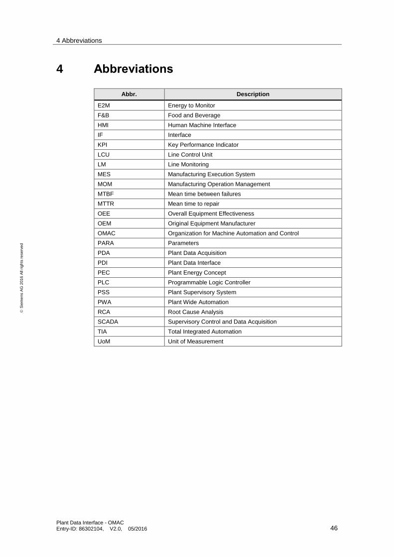
4 Abbreviations
Plant Data Interface - OMAC Entry-ID: 86302104, V2.0, 05/2016 46
S
iem
en
s A
G 2
01
6 A
ll ri
gh
ts r
ese
rve
d
4 Abbreviations
Abbr. Description
E2M Energy to Monitor
F&B Food and Beverage
HMI Human Machine Interface
IF Interface
KPI Key Performance Indicator
LCU Line Control Unit
LM Line Monitoring
MES Manufacturing Execution System
MOM Manufacturing Operation Management
MTBF Mean time between failures
MTTR Mean time to repair
OEE Overall Equipment Effectiveness
OEM Original Equipment Manufacturer
OMAC Organization for Machine Automation and Control
PARA Parameters
PDA Plant Data Acquisition
PDI Plant Data Interface
PEC Plant Energy Concept
PLC Programmable Logic Controller
PSS Plant Supervisory System
PWA Plant Wide Automation
RCA Root Cause Analysis
SCADA Supervisory Control and Data Acquisition
TIA Total Integrated Automation
UoM Unit of Measurement
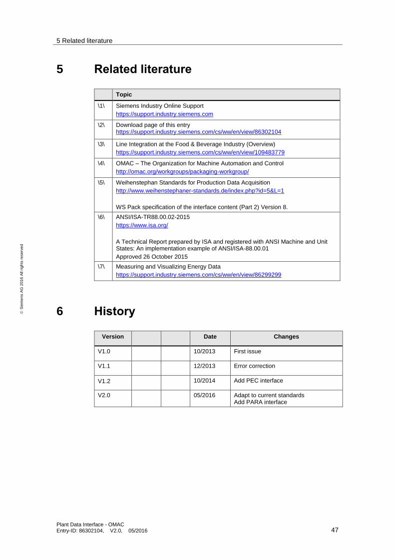
5 Related literature
Plant Data Interface - OMAC Entry-ID: 86302104, V2.0, 05/2016 47
S
iem
en
s A
G 2
01
6 A
ll ri
gh
ts r
ese
rve
d
5 Related literature
Topic
\1\ Siemens Industry Online Support
https://support.industry.siemens.com
\2\ Download page of this entry https://support.industry.siemens.com/cs/ww/en/view/86302104
\3\ Line Integration at the Food & Beverage Industry (Overview)
https://support.industry.siemens.com/cs/ww/en/view/109483779
\4\ OMAC – The Organization for Machine Automation and Control
http://omac.org/workgroups/packaging-workgroup/
\5\ Weihenstephan Standards for Production Data Acquisition
http://www.weihenstephaner-standards.de/index.php?id=5&L=1
WS Pack specification of the interface content (Part 2) Version 8.
\6\ ANSI/ISA-TR88.00.02-2015
https://www.isa.org/
A Technical Report prepared by ISA and registered with ANSI Machine and Unit States: An implementation example of ANSI/ISA-88.00.01
Approved 26 October 2015
\7\ Measuring and Visualizing Energy Data
https://support.industry.siemens.com/cs/ww/en/view/86299299
6 History
Version
Date Changes
V1.0
10/2013 First issue
V1.1
12/2013 Error correction
V1.2
10/2014 Add PEC interface
V2.0
05/2016 Adapt to current standards Add PARA interface


