https://support.industry.siemens.com/cs/ww/en/view/109480894 Application Example 12/2015 SINAMICS V: Simple Speed Control of a V20 with S7-1200/1500 Using the USS® Protocol SINAMICS V20 (Firmware ≥ V3.51) SIMATIC S7-1200 (Firmware ≥ V4.1), SIMATIC S7-1500 (Firmware ≥ V1.7)
SINAMICS V: Simple Speed Control of a V20 with S7-1200/1500 Using the USS® Protocol SINAMICS V20 (Firmware ≥ V3.51) SIMATIC S7-1200 (Firmware ≥ V4.1), SIMATIC S7-1500 (Firmware ≥ V1.7)
SINAMICS V20 at S7-1200/1500 via USS Entry ID: 109480894, V1.0, 12/2015 2
S
iem
en
s A
G 2
01
5 A
ll ri
gh
ts r
ese
rve
d
Warranty and Liability
Note The Application Examples are not binding and do not claim to be complete regarding the circuits shown, equipping and any eventuality. The Application Examples do not represent customer-specific solutions. They are only intended to provide support for typical applications. You are responsible for ensuring that the described products are used correctly. These Application Examples do not relieve you of the responsibility to use safe practices in application, installation, operation and maintenance. When using these Application Examples, you recognize that we cannot be made liable for any damage/claims beyond the liability clause described. We reserve the right to make changes to these Application Examples at any time without prior notice. If there are any deviations between the recommendations provided in this Application Example and other Siemens publications – e.g. Catalogs – the contents of the other documents shall have priority.
We do not accept any liability for the information contained in this document.
Any claims against us – based on whatever legal reason – resulting from the use of the examples, information, programs, engineering and performance data etc., described in this application example shall be excluded. Such an exclusion shall not apply in the case of mandatory liability, e.g. under the German Product Liability Act (“Produkthaftungsgesetz”), in case of intent, gross negligence, or injury of life, body or health, guarantee for the quality of a product, fraudulent concealment of a deficiency or breach of fundamental contractual obligations (“wesentliche Vertragspflichten”). The damages for a breach of a substantial contractual obligation are, however, limited to the foreseeable damage, typical for the type of contract, except in the event of intent or gross negligence or injury to life, body or health. The above provisions do not imply a change of the burden of proof to your detriment.
Any form of duplication or distribution of these Application Examples or excerpts hereof is prohibited without the expressed consent of Siemens AG.
Security informa-
tion
Siemens provides products and solutions with industrial security functions that support the secure operation of plants, solutions, machines, equipment and/or networks. They are important components in a holistic industrial security concept. With this in mind, Siemens’ products and solutions undergo continuous development. Siemens recommends strongly that you regularly check for product updates.
For the secure operation of Siemens products and solutions, it is necessary to take suitable preventive action (e.g. cell protection concept) and integrate each component into a holistic, state-of-the-art industrial security concept. Third-party products that may be in use should also be considered. For more information about industrial security, visit http://www.siemens.com/industrialsecurity.
To stay informed about product updates as they occur, sign up for a product-specific newsletter. For more information, visit http://support.industry.siemens.com.
1.1 Overview............................................................................................... 4 1.2 Operation of the drive ........................................................................... 4
4 Configuration and Project Engineering ......................................................... 19
4.1 Parameterizing the SINAMICS V20 ................................................... 19 4.2 Configuring the SIMATIC controller ................................................... 21 4.3 Configuring the SIMATIC HMI KTP600 operator panel ..................... 24
5 Installation and Commissioning .................................................................... 27
5.1 Installing the hardware ....................................................................... 27 5.2 Installing the software (download) ...................................................... 30 5.3 Commissioning ................................................................................... 32
6 Operation of the Application .......................................................................... 33
6.1 Operator control using the HMI .......................................................... 33 6.1.1 Switching on the operator panel ......................................................... 33 6.1.2 Operating screen ................................................................................ 33 6.2 Operator control using the watch table .............................................. 34
7 Expansion to multiple Slaves ......................................................................... 35
7.1 Expansion to multiple slaves with S7-1200 ........................................ 35 7.2 Expansion to multiple slaves with S7-1500 ........................................ 37
8 Links & Literature ............................................................................................ 40
SINAMICS V20 at S7-1200/1500 via USS Entry ID: 109480894, V1.0, 12/2015 4
S
iem
en
s A
G 2
01
5 A
ll ri
gh
ts r
ese
rve
d
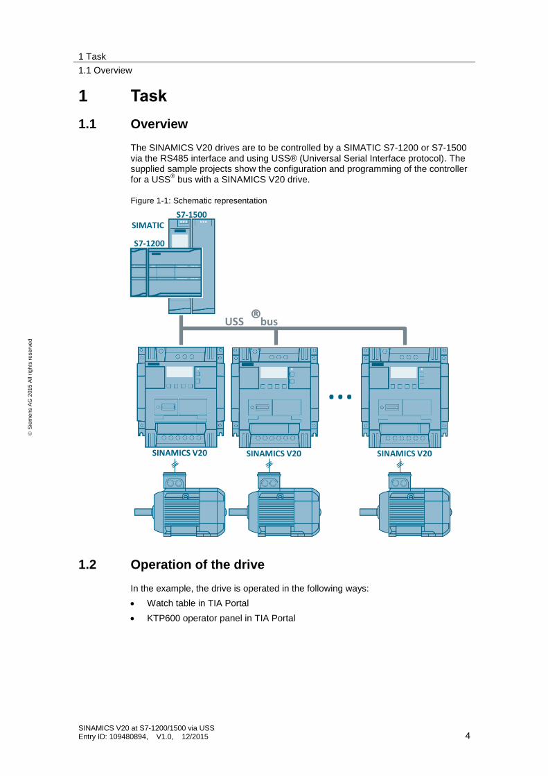
1 Task
1.1 Overview
The SINAMICS V20 drives are to be controlled by a SIMATIC S7-1200 or S7-1500 via the RS485 interface and using USS® (Universal Serial Interface protocol). The supplied sample projects show the configuration and programming of the controller for a USS
® bus with a SINAMICS V20 drive.
Figure 1-1: Schematic representation
…
USS bus®
S7-1200
S7-1500
SINAMICS V20 SINAMICS V20 SINAMICS V20
SIMATIC
1.2 Operation of the drive
In the example, the drive is operated in the following ways:
Watch table in TIA Portal
KTP600 operator panel in TIA Portal
1 Task
1.2 Operation of the drive
SINAMICS V20 at S7-1200/1500 via USS Entry ID: 109480894, V1.0, 12/2015 5
S
iem
en
s A
G 2
01
5 A
ll ri
gh
ts r
ese
rve
d
Control
The SINAMICS V20 drive is to be controlled via the following bit signals of the control word (STW):
ON/OFF1 – start bit of the SINAMICS V20 (STW1, bit 0) If this parameter has the value TRUE, this input enables operation of the V20 at the preset speed.
OFF2 – coast down to a standstill (STW1, bit 1) If this parameter has the value FALSE, this bit causes the SINAMICS V20 to coast down to a standstill, without braking.
OFF3 – fast stop bit (STW1, bit 2) If this parameter has the value FALSE, this bit causes a fast stop by braking the SINAMICS V20.
Fault ack. – error acknowledgment bit (STW1, bit 7) With this bit, you reset the error bit of the SINAMICS V20 once you have eliminated the drive fault. This informs the drive that it is no longer necessary to signal the fault.
Reverse – direction control of the SINAMICS V20 (STW1, bit 11) This bit has to be set for clockwise rotation (provided that the speed setpoint is positive).
Entering the speed
Speed setpoint (HSW) This is the speed setpoint of the SINAMICS V20 as a percentage of the configured frequency. When entering a positive value, the motor rotates clockwise if Reverse
has the value TRUE.
Status evaluation
The SINAMICS V20 drive is to continuously transfer the following bit signals of the status word (STW) to the controller:
Inverter running – operation enabled (ZSW1, bit 2) This bit signals whether the SINAMICS V20 is running.
Motor runs right – drive direction (ZSW1, bit 14) This bit signals clockwise rotation of the motor.
ON inhibit active – SINAMICS V20 inhibit (ZSW1, bit 6)
This bit signals the status of the inhibit bit for the SINAMICS V20.
Inverter fault active – drive fault (ZSW1, bit 3) This bit signals that a fault has occurred in the SINAMICS V20. The user has to eliminate the fault and set the acknowledgment bit (STW1, bit 7) to delete this bit.
Transferring the actual speed
Actual speed (HIW) This is the actual speed of the SINAMICS V20 as a percentage of the configured frequency. When the value is positive, the motor rotates clockwise if Motor runs right has the value TRUE.
Display of communication errors
In the event of a communication error, the error status of the USS®
system instructions of the STEP 7 program is to be displayed.
2 Solution
2.1 Overview
SINAMICS V20 at S7-1200/1500 via USS Entry ID: 109480894, V1.0, 12/2015 6
S
iem
en
s A
G 2
01
5 A
ll ri
gh
ts r
ese
rve
d
2 Solution
2.1 Overview
Diagrammatic representation
To connect the bus, you need a RS485 communication module for both the SIMATIC S7-1200 and the S7-1500. This module is operated in the control program by USS system statements. The figure below shows the basic configuration.
Figure 2-1: Function chart
PLC
User program
Cyclic interrupt OB
Process communicationvia USS network
(system instructions:USS_PORT / USS_Port_Scan)
……
CM USS® bus
SIMATIC S7-1200/1500
PG/PCKTP600 (optional)
Industrial Ethernet
SINAMICS V20Cycle OB
Prepare and displaydata for drive
(system instructions:USS_DRV / USS_Drive_Control)
……
…
Scope
To the extent not necessary for understanding this application example, this document does not contain a general description of
the hardware components used.
TIA Portal.
the STEP 7 and WinCC configuration software.
the USS® protocol.
Basic knowledge of these topics is required.
2 Solution
2.2 Hardware and software components
SINAMICS V20 at S7-1200/1500 via USS Entry ID: 109480894, V1.0, 12/2015 7
S
iem
en
s A
G 2
01
5 A
ll ri
gh
ts r
ese
rve
d
Required knowledge
Knowledge of automation and drive technology is helpful to understand the application example. You need basic knowledge of SINAMICS drives and configuring SIMATIC controllers in TIA Portal.
2.2 Hardware and software components
2.2.1 Validity
This application is valid for
SINAMICS V20 with the following firmware version data or higher:
Table 2-1: SINAMICS V20 firmware version data
Parameter Index Meaning Value
r0018 - Firmware version 3.51
r0964
[0] Company (Siemens = 42) 42
[1] Product type (V20 = 8001) 8001
[2] Firmware version 351
[3] Firmware date (year) 2012
[4] Firmware date (day/month) 1012
[5] Number of inverters 1
[6] Firmware version 500
S7-1200 PLC with firmware V4.1 or higher1
S7-1200 CM1241 communication module with firmware V2.1 or higher
S7-1200 CB1241 communication board with firmware V1.0 or higher
S7-1500 controller with firmware V1.7 or higher
S7-1500 CM PtP communication module with firmware V1.0 or higher
STEP 7 software V13 SP1 or higher
2.2.2 Components used
The application was created with the following components.
Hardware components
The following table contains only the main components necessary from a functional perspective. It does not list
line-side components such as circuit-breakers, fuses or line filters.
load-dependent components such as braking resistors.
fixing accessories such as mounting rails.
standard wiring material and terminal blocks.
other small accessories.
1 Please note: An update to ≥V4.1 is only possible for S7-1200 controllers with article numbers
…….-1xx40-….
2 Solution
2.2 Hardware and software components
SINAMICS V20 at S7-1200/1500 via USS Entry ID: 109480894, V1.0, 12/2015 8
S
iem
en
s A
G 2
01
5 A
ll ri
gh
ts r
ese
rve
d
Table 2-2: Hardware components
Component No. Article number Note
Drive components
SINAMICS V20
(3AC400V, 0.75KW, FILTER C3)
1 6SL3210-5BE17-5CV0
… or any other SINAMICS V20 with a firmware version listed in 2.2.1.
SIMOTICS GP
low-voltage motor, 3 AC 50Hz 400V, 0.75 KW
1 1LA7083-4AA60
… or any other asynchronous motor that complies with the specification of the SINAMICS V20 used.
S7-1200 controller components
SIMATIC S7-1200 CPU 1215
1 6ES7511-1AK01-0AB0
For the required firmware version, see section 2.2.1.
SIMATIC S7-1200 CM1241 communication module 1
alte
rna
tive
ly
6ES7241-1CH32-0XB0
SIMATIC S7-1200 CB1241 communication board
6ES7241-1CH30-1XB0
PROFIBUS connector 1 6ES7972-… For bus connection on the CM 1241
S7-1500 controller components
SIMATIC S7-1500 CPU 1511-1 PN
1 6ES7511-1AK01-0AB0 ... or any other S7-1500 CPU with firmware V1.7 or higher.
SIMATIC S7-1500 CM PTP RS422/485 HF communication module
1
alte
rna
tive
ly
6ES7541-1AB00-0AB0
SIMATIC S7-1500 CM PTP RS422/485 BA communication module
6ES7540-1AB00-0AA0
When using this communication module, reduce the baud rate in the control software of the application example to ≤ 19.2 kbit/s and replace the hardware ID of the CM PtP.
SUB-D connector, 15-pin
1 - For bus connection on the CM PtP
HMI
SIMATIC HMI KTP600 Basic color PN
(1) 6AV6647-0AD11-3AX0 … can be simulated in TIA Portal for test and demonstration purposes
Other
SITOP PSU100L stabilized 24V power supply
1 6EP1333-1LB00
24V power supply for SIMATIC CPU and KTP600. You can also use a different power supply that meets the requirements of the loads.
The following list contains all files and projects that are used in this example.
Table 2-4: Sample files and projects
Documents Note
109480894_V20USSatS7-12001500_DOC_V1d0_TIAV13SP1_en.pdf ... this document
109480894_V20USSatS7-1200_PROJ_V1d0_TIAV13SP1.zip TIA project with S7-1200
109480894_V20USSatS7-1500_PROJ_V1d0_TIAV13SP1.zip TIA project with S7-1500
3 Principle of Operation
3.1 Complete overview
SINAMICS V20 at S7-1200/1500 via USS Entry ID: 109480894, V1.0, 12/2015 10
S
iem
en
s A
G 2
01
5 A
ll ri
gh
ts r
ese
rve
d
3 Principle of Operation
3.1 Complete overview
3.1.1 Basic software structure
The USS protocol uses a master/slave network for communication via a serial bus. The master (SIMATIC controller) uses an address parameter to send a message to a selected slave (SINAMICS V20). A slave cannot send without having received a request for sending. Direct information transmission between the individual slaves is not possible. USS communication takes place in half duplex operation.
In STEP 7, different libraries have to be used for the S7-1200 and S7-1500 controllers. However, their system blocks are handled similarly.
The STEP 7 program is divided into an interrupt-driven part and a program part to be cyclically processed.
Interrupt-driven part This part calls a USS_PORT (S7-1200) or USS-Port_Scan (S7-1500) system instruction from a cyclic interrupt OB for each communication port. This system instruction processes communication via the USS network.
Cyclic part This part calls a USS_DRV (S7-1200) or USS_Drive_Control (S7-1500) system instruction on the respective port from a cycle OB for each existing slave. This system instruction prepares send data for the drive and evaluates the drive’s response data.
3.1.2 Implementation with SIMATIC S7-1200
Use the following system instructions:
USS_PORT to process communication via the USS
® network
USS_DRV to prepare the send data and evaluate the response data
These system instructions can be found in the Instructions task card, Communication.
3 Principle of Operation
3.1 Complete overview
SINAMICS V20 at S7-1200/1500 via USS Entry ID: 109480894, V1.0, 12/2015 11
S
iem
en
s A
G 2
01
5 A
ll ri
gh
ts r
ese
rve
d
Figure 3-1: USS instructions for S7-1200
Note The instructions in the USS Communication folder are currently not suitable for the S7-1200 in this application example.
The following figure shows the call structure of the program example.
Figure 3-2: Block call diagram for SIMATIC S7-1200
User program System blocks Data blocks
Main
[OB1]
InstUssCyclic
[DB1](instance DB of FB UssCyclic)
UssCyclic
[FB1]
USS_DRV
[FB1071]
InstUssDrv
[DB3](instance DB of FB USS_DRV)
Cyclic interrupt
[OB30]
USS_PORT
[FC1070]
InstUssCyclicInterrupt
[DB2](instance DB of FB
UssCyclicInterrupt)
UssCyclicInterrupt
[FB2]
The UssCyclic and UssCyclicInterrupt user blocks use optimized block access.
3 Principle of Operation
3.1 Complete overview
SINAMICS V20 at S7-1200/1500 via USS Entry ID: 109480894, V1.0, 12/2015 12
S
iem
en
s A
G 2
01
5 A
ll ri
gh
ts r
ese
rve
d
Note Know-how protected use of the UssCyclic user block in a library is not possible.
Reason: The USS_DRV system FB cannot put its data into the InstUssCyclic instance DB of the calling UssCyclic block as a multi-instance; it uses the InstUssDrv single instance. This is necessary as the USS_PORT system FB can only access the entire instance DB of USS_DRV via its USS_DB formal parameter of the USS_BASE data type; it cannot access an instance data block within InstUssCyclic.
3.1.3 Implementation with SIMATIC S7-1500
Use the following system instructions:
USS_Port_Scan
to process communication via the USS® network
USS_Drive_Control
to prepare the send data and evaluate the response data
These system instructions can be found in the Instructions task card, Communication.
Figure 3-3: USS instructions for S7-1500
3 Principle of Operation
3.2 Blocks
SINAMICS V20 at S7-1200/1500 via USS Entry ID: 109480894, V1.0, 12/2015 13
S
iem
en
s A
G 2
01
5 A
ll ri
gh
ts r
ese
rve
d
Figure 3-4: Block call diagram for SIMATIC S7-1500
User program System blocks Data blocks
Main
[OB1]
InstUssCyclic
[DB1](instance DB of FB UssCyclic)
UssCyclic
[FB1]
USS_Drive_Control
[FB631]
Cyclic interrupt
[OB30]
USS_Port_Scan
[FB630]
InstUssCyclicInterrupt
[DB2](instance DB of FB
UssCyclicInterrupt)
UssCyclicInterrupt
[FB2]
instUssDriveControl
USS_DB
The UssCyclic and UssCyclicInterrupt user blocks use optimized block access.
3.2 Blocks
3.2.1 UssCyclicInterrupt [FB2]
Call
All activities relating to processing USS communication for the communication module with the parameterized hardware ID should be combined in this block.
Figure 3-5: UssCyclicInterrupt user FB
The block name is intended to indicate that the block is called by the cyclic interrupt OB.
3 Principle of Operation
3.2 Blocks
SINAMICS V20 at S7-1200/1500 via USS Entry ID: 109480894, V1.0, 12/2015 14
S
iem
en
s A
G 2
01
5 A
ll ri
gh
ts r
ese
rve
d
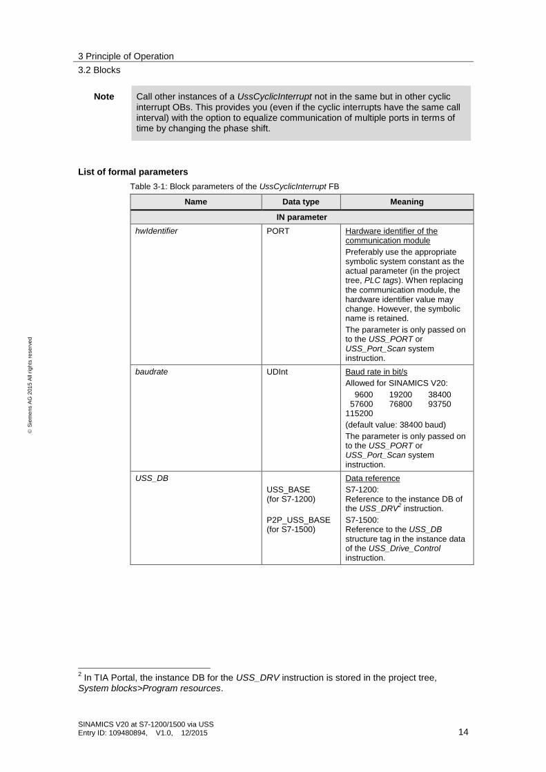
Note Call other instances of a UssCyclicInterrupt not in the same but in other cyclic interrupt OBs. This provides you (even if the cyclic interrupts have the same call interval) with the option to equalize communication of multiple ports in terms of time by changing the phase shift.
List of formal parameters
Table 3-1: Block parameters of the UssCyclicInterrupt FB
Name Data type Meaning
IN parameter
hwIdentifier PORT Hardware identifier of the communication module
Preferably use the appropriate symbolic system constant as the actual parameter (in the project tree, PLC tags). When replacing
the communication module, the hardware identifier value may change. However, the symbolic name is retained.
The parameter is only passed on to the USS_PORT or USS_Port_Scan system instruction.
baudrate UDInt Baud rate in bit/s
Allowed for SINAMICS V20:
0 9600 019200 038400 057600 076800 093750 115200
(default value: 38400 baud)
The parameter is only passed on to the USS_PORT or USS_Port_Scan system instruction.
USS_DB
USS_BASE (for S7-1200)
P2P_USS_BASE (for S7-1500)
Data reference
S7-1200: Reference to the instance DB of the USS_DRV
2 instruction.
S7-1500: Reference to the USS_DB structure tag in the instance data of the USS_Drive_Control instruction.
2 In TIA Portal, the instance DB for the USS_DRV instruction is stored in the project tree,
System blocks>Program resources.
3 Principle of Operation
3.2 Blocks
SINAMICS V20 at S7-1200/1500 via USS Entry ID: 109480894, V1.0, 12/2015 15
S
iem
en
s A
G 2
01
5 A
ll ri
gh
ts r
ese
rve
d
Name Data type Meaning
OUT parameter
errorUss Bool Communication error
Saved ERROR error bit of the USS_PORT or USS_Port_Scan
3
system instruction. In the example, this error bit is reset using the HMI or the watch table.
errorStatusUss Word Error code
Saved STATUS error code of the USS_PORT or USS_Port_Scan
3
system instruction. In the example, this error code is reset to 0000hex using the HMI or the watch table.
Function
In this application example, the block has only the following tasks:
Calls and supplies the USS_PORT system instruction
Saves the USS_PORT output parameter STATUS when ERROR = true
Call interval
On the one hand, the call interval of the cyclic interrupt OB in which the UssCyclicInterrupt user FB and finally the UDD_PORT or USS_Port_Scan system
instruction are called
should be as short as possible to minimize the communication time;
on the other hand, it must be long enough to process each communication request reliably without errors.
3.2.2 UssCyclic [FB1]
Call
All activities to be cyclically performed while processing USS communication should be combined in this block.
Figure 3-6: UssCyclic user FB
The block name is intended to indicate that the FB is called by a cycle OB.
3 Communication errors are only signaled at the ERROR and STATUS outputs of the
*) USS_PORT instruction. Therefore, it is sufficient to read out the error code of this *) system instruction.
3 Principle of Operation
3.2 Blocks
SINAMICS V20 at S7-1200/1500 via USS Entry ID: 109480894, V1.0, 12/2015 16
S
iem
en
s A
G 2
01
5 A
ll ri
gh
ts r
ese
rve
d
Table 3-2: Block parameters of the UssCyclic FB
Name Data type Meaning
IN parameter
STW Word Control word of the SINAMICS V20
With the UssCyclic FB, the following STW bits can be transferred to the SINAMICS V20:
Specified as a percentage of the frequency of the inverter output and therefore independent of the pole pair number and motor slip.
OUT parameter
ZSW Word Status word of the SINAMICS V20
With the UssCyclic FB, the
following ZSW bits can be received from the SINAMICS V20:
Inverter running (bit 02) Motor runs right (bit 14) ON inhibit active (bit 06) Inverter fault active (bit 03)
actual Speed Real Actual speed
Specified as a percentage of the frequency of the inverter output and therefore independent of the pole pair number and motor slip.
Function
In this application example, the block only has the task to ensure the supply of the called USS_DRV or USS_Drive_Control system instruction.
The following default settings were made in the associated InstUssCyclic instance
DB:
STW = 0806hex This means that bits 01 (OFF2), 02 (OFF3) and 11 (Reverse) have already been set when the controller is restarted.
speedSetpoint = 50.0 Ensures that the drive immediately ramps up with the parameterized ramp-up time to 50% of its rated speed when the ON/OFF1 button is pressed.
3 Principle of Operation
3.2 Blocks
SINAMICS V20 at S7-1200/1500 via USS Entry ID: 109480894, V1.0, 12/2015 17
S
iem
en
s A
G 2
01
5 A
ll ri
gh
ts r
ese
rve
d
3.2.3 USS® system instructions
USS_PORT (S7-1200) / USS_Port_Scan (S7-1500)
Figure 3-7: USS_PORT or USS_Port_Scan system instruction
The USS_PORT system FB is described in the STEP 7 Basic System Manual in \6\
or in the appropriate section of the online help in TIA Portal.
The USS_Port_Scan system FB is described in the STEP 7 Professional System
Manual in \5\ or in the appropriate section of the online help in TIA Portal.
3 Principle of Operation
3.2 Blocks
SINAMICS V20 at S7-1200/1500 via USS Entry ID: 109480894, V1.0, 12/2015 18
S
iem
en
s A
G 2
01
5 A
ll ri
gh
ts r
ese
rve
d
USS_DRV (S7-1200) / USS_Drive_Control (S7-1500)
Figure 3-8: USS_DRV or USS_Drive_Control system instruction
The USS_DRV system FB is described in the STEP 7 Basic System Manual in \6\ or in the appropriate section of the online help in TIA Portal.
4
The USS_Drive_Control system FB is described in the STEP 7 Professional System Manual in \5\ or in the appropriate section of the online help in TIA Portal.
4 The symbolic name of the instruction is USS_DRV. In the manual and online help, it is called
USS_DRIVE.
4 Configuration and Project Engineering
4.1 Parameterizing the SINAMICS V20
SINAMICS V20 at S7-1200/1500 via USS Entry ID: 109480894, V1.0, 12/2015 19
S
iem
en
s A
G 2
01
5 A
ll ri
gh
ts r
ese
rve
d
4 Configuration and Project Engineering This chapter describes the configuration steps necessary for you to create the sample project. You will find helpful project engineering support, in particular if your required configuration differs from the supplied application example in terms of hardware and component parameterization.
Requirement
Configuration software The software components are installed on your development system according to Table 2-3.
SINAMICS V20 The parameterization is performed using the built-in BOP (Basic Operator Panel). Therefore, on the line side, the drive has already been supplied with
230 or 400V – depending on the version.
SIMATIC S7-1200/1500 In TIA Portal, you have opened a new software project or a project to be expanded/modified.
Default values
The below parameterization of the SINAMICS V20 assumes that the device is in the as-supplied state or has been reset to factory default. In this state, there is a default parameterization that forms the basis for Table 4-1. Parameters that do not have to be changed for this application example regarding the default values will not be mentioned in the following sections.
When you add a device, for example a controller, from the hardware catalog to the project in TIA Portal, an associated default parameterization will be created. This default parameterization will be used as a basis in Table 4-2. Parameters and settings that do not have to be changed for this application example regarding the default values will not be mentioned in the following sections.
Note Both the procedure for parameterizing the SINAMICS V20 and the one for configuring the SIMATIC controllers in TIA Portal offer various options. The following configuration steps represent one possible solution. Steps or procedures deviating from this approach can also lead to the same goal.
4.1 Parameterizing the SINAMICS V20
Table 4-1: Table for parameterizing the SINAMICS V20 drive
No. Action
General:
The SINAMICS V20 is parameterized using the built-in BOP. For information on how to use the BOP, please refer to the SINAMICS V20 Operating Instructions in \10\.
Unless expressly noted, press the and buttons <2s.
4 Configuration and Project Engineering
4.1 Parameterizing the SINAMICS V20
SINAMICS V20 at S7-1200/1500 via USS Entry ID: 109480894, V1.0, 12/2015 20
S
iem
en
s A
G 2
01
5 A
ll ri
gh
ts r
ese
rve
d
No. Action
1. Provided that the SINAMICS V20 is in the as-supplied state and the display displays , continue with no. 2.
If the inverter has already been running, the display menu with the output frequency is visible on the BOP. In this case, reset the device to factory default. To do this, use to go from the display menu to the parameter menu and change the following parameters:
Commissioning parameter P0010 030 (LED on the BOP flashes green.)
Reset to factory setting5 P0970 21
2. The display displays and the LED on the BOP has a steady green light.
Use the arrow keys to select the 50/60 or Hz/hp setting that matches your region and use to exit the screen.
3. The LED on the BOP flashes green. You are now in the setup menu in the “Motor data” step and, provided that you are running the example with a connected motor, you can start entering the motor parameters. When you have finished entering the motor parameters or if you do not want to enter any motor parameters, press . You are now in the “Connection macro” step.
4. Use the arrow keys to choose the connection macro (Cn010) and use to select it.
5. Use (>2s) to return to the display menu. The LED on the BOP returns to a steady green light.
6. Use to go to the parameter menu and set the user access level to “Expert”:
Access level P0003 3
7. Set the USS PKW length to 4:
PKW length P2013 4
8. Transfer the changed parameter values from RAM to EEPROM:
RAM to EEPROM P0971 21
9. Set the access level back to “Standard”.
Access level P0003 1
10. Use (>2s) to return to the display menu.
5 When resetting to factory default, connection parameters P2010, P2011, P2023 used for the
USS protocol are not automatically reset in the process. However, they are supplied in step 4 of the table.
4 Configuration and Project Engineering
4.2 Configuring the SIMATIC controller
SINAMICS V20 at S7-1200/1500 via USS Entry ID: 109480894, V1.0, 12/2015 21
S
iem
en
s A
G 2
01
5 A
ll ri
gh
ts r
ese
rve
d
4.2 Configuring the SIMATIC controller
The screenshots in the following table are from the V20USSatS7-1200 STEP 7 project. Deviations due to the use of the V20USSatS7-1500 project are indicated in the text.
Table 4-2: Table for configuring the SIMATIC S7-1200 controller
No. Action
1. In the project tree, go to Devices & networks and select the Network view. In the Hardware catalog task card, locate the SIMATIC S7-1200 CPU 1215C DC/DC/DC or SIMATIC S7-1500 CPU 1511-1 PN and use drag and drop to move it to the graphic area of the Network view. In this area and in the project tree, it will be created as PLC_1
6. Select the CPU with a version ≥V4.1 (S7-1200) or
≥V1.7 (S7-1500).
6 Name can be changed.
4 Configuration and Project Engineering
4.2 Configuring the SIMATIC controller
SINAMICS V20 at S7-1200/1500 via USS Entry ID: 109480894, V1.0, 12/2015 22
S
iem
en
s A
G 2
01
5 A
ll ri
gh
ts r
ese
rve
d
No. Action
2. In the graphic area, select the SIMATIC controller and go to the Device view. In the Hardware catalog task card, locate the
CM1241 (RS422/485) communication module, version ≥V2.1, for the CPU 1215C
CM PtP RS422/485 HF communication module, version ≥V1.0 for the CPU 1511-1 PN
and use drag and drop to move it to an allowed slot next to the CPU in the graphic area of the Network view.
3. If necessary, change the Ethernet address. To do this, double-click the CPU to open its properties.
4 Configuration and Project Engineering
4.2 Configuring the SIMATIC controller
SINAMICS V20 at S7-1200/1500 via USS Entry ID: 109480894, V1.0, 12/2015 23
S
iem
en
s A
G 2
01
5 A
ll ri
gh
ts r
ese
rve
d
No. Action
4. Create your user program or – if you want to use the supplied sample program – copy the following objects from the sample program to your new project:
5. Compile the PLC_1 device in order to detect possible errors.
You can ignore the warning displayed when compiling the device.
6. Save the project.
For the copy operation, you can open both TIA projects at the same time. In the dialog regarding conflicts when copying, select Replace existing objects and move to this location.
4 Configuration and Project Engineering
4.3 Configuring the SIMATIC HMI KTP600 operator panel
SINAMICS V20 at S7-1200/1500 via USS Entry ID: 109480894, V1.0, 12/2015 24
S
iem
en
s A
G 2
01
5 A
ll ri
gh
ts r
ese
rve
d
4.3 Configuring the SIMATIC HMI KTP600 operator panel
Table 4-3: Table for configuring the SIMATIC HMI KTP600 operator panel
No. Action
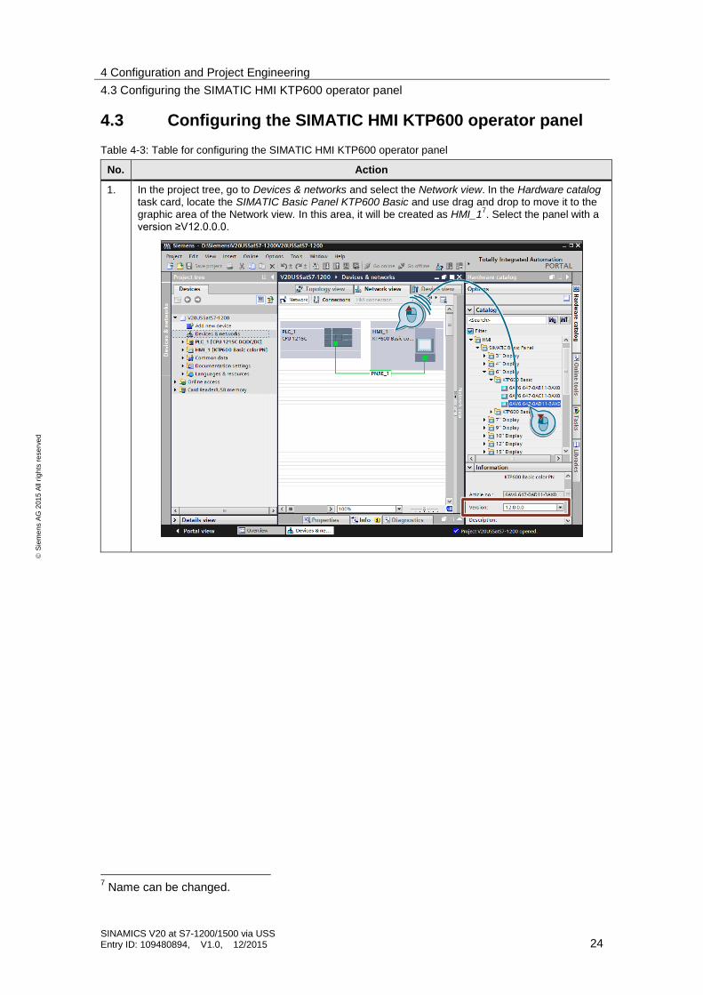
1. In the project tree, go to Devices & networks and select the Network view. In the Hardware catalog task card, locate the SIMATIC Basic Panel KTP600 Basic and use drag and drop to move it to the graphic area of the Network view. In this area, it will be created as HMI_1
7. Select the panel with a
version ≥V12.0.0.0.
7 Name can be changed.
4 Configuration and Project Engineering
4.3 Configuring the SIMATIC HMI KTP600 operator panel
SINAMICS V20 at S7-1200/1500 via USS Entry ID: 109480894, V1.0, 12/2015 25
S
iem
en
s A
G 2
01
5 A
ll ri
gh
ts r
ese
rve
d
No. Action
Alternatively, you can also copy the fully configured operator panel from the supplied sample project to your new project. For the copy operation, you can open both TIA projects at the same time and use drag and drop to move the HMI device via from the graphic area of the Network view of the source project to the one of the target project.
2. Continue with step 3, provided that you have newly added the HMI device from the catalog. If you have added the HMI device by copying it, you have to delete the old connection.
Sample project
Your user project
4 Configuration and Project Engineering
4.3 Configuring the SIMATIC HMI KTP600 operator panel
SINAMICS V20 at S7-1200/1500 via USS Entry ID: 109480894, V1.0, 12/2015 26
S
iem
en
s A
G 2
01
5 A
ll ri
gh
ts r
ese
rve
d
No. Action
3. Configure a new HMI connection in the Network view. To do this, use drag and drop to connect the Ethernet interfaces of PLC_1 and HMI_1. As a consequence, HMI_Connection_1
8 will be created.
4. Compile the HMI_1 device in order to detect possible errors and save its configuration.
8 Name can be changed.
1 2
5 Installation and Commissioning
5.1 Installing the hardware
SINAMICS V20 at S7-1200/1500 via USS Entry ID: 109480894, V1.0, 12/2015 27
S
iem
en
s A
G 2
01
5 A
ll ri
gh
ts r
ese
rve
d
5 Installation and Commissioning
5.1 Installing the hardware
Note Always follow the installation, mounting and wiring guidelines for the individual components provided in the appropriate manuals and accompanying notes.
Table 5-1: Table for installing and wiring the hardware
No. Action
1. Mechanically install the hardware. (SINAMICS V20, motor if applicable, SIMATIC controller, operator panel, 24V power supply unit)
2. On the secondary side, connect the asynchronous motor (if applicable) to the SINAMICS V20.
On the primary side, connect the SINAMICS V20 to the main circuit.
3. Wire the 24 V DC connector of the SIMATIC S7 controller to the output of the 24V power supply unit. If you are connecting an operator panel, wire also the OP’s 24 V DC connector to the output of the 24V power supply unit.
4. Establish the USS® bus connection between the communications processor of the CPU and the
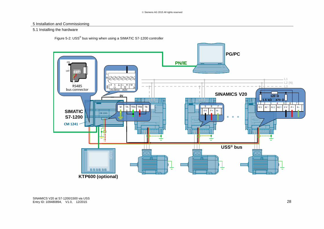
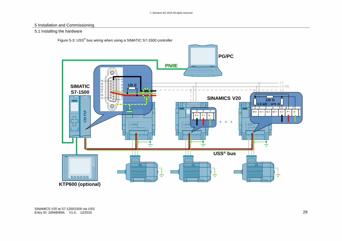
SINAMICS V20. Provide bus termination and line polarization. For the bus design and wiring, always comply with the appropriate RS-485 interface standard specifications.
For suggestions on wiring the networks with S7-1200 and S7-1500, please refer to the figures following this table. For bus termination where no RS485 bus connector (PROFIBUS connector) can be used, Siemens offers a bus termination network (for the article number, see Table 2-2).
Figure 5-1: Bus termination network
Bus cable:
A screened 2- or 3-core cable (e.g., PROFIBUS cable9; for the article number, see Table 2-2) is
suitable as a bus cable for a connection based on RS485. As you have to connect the M potentials of all bus nodes, you need a separate ground wire if you are using a twisted pair cable as a bus cable.
5. Use an Industrial Ethernet cable to connect the SIMATIC CPU (e.g., port 1) to the KTP600 operator panel, provided that you do not only want to simulate the HMI in TIA Portal.
6. Use an Industrial Ethernet cable to connect the SIMATIC CPU (e.g., port 2) to your development system.
9 Please note that its external cross section may not be compatible with all SUB-D connectors.
5 Installation and Commissioning
5.1 Installing the hardware
SINAMICS V20 at S7-1200/1500 via USS Entry ID: 109480894, V1.0, 12/2015 28
Siemens AG 2015 All rights reserved
Figure 5-2: USS® bus wiring when using a SIMATIC S7-1200 controller
…
PN/IE
PG/PC
SINAMICS V20
L1
L2 (N)
L3
1.5 kΩ 470 Ω
120 Ω
KTP600 (optional)
SIMATIC
S7-1200
USS® bus
0V
ON
OFF
RS485bus connector
M TA TRA TRB TB
CM 1241
CB 1241
5 Installation and Commissioning
5.1 Installing the hardware
SINAMICS V20 at S7-1200/1500 via USS Entry ID: 109480894, V1.0, 12/2015 29
Siemens AG 2015 All rights reserved
Figure 5-3: USS® bus wiring when using a SIMATIC S7-1500 controller
…
PG/PC
SINAMICS V20
L1
L2 (N)
L3
1.5 kΩ 470 Ω
120 Ω
KTP600 (optional)
SIMATIC
S7-1500
USS® bus
120 Ω
PN/IE
CM
PtP
5 Installation and Commissioning
5.2 Installing the software (download)
SINAMICS V20 at S7-1200/1500 via USS Entry ID: 109480894, V1.0, 12/2015 30
S
iem
en
s A
G 2
01
5 A
ll ri
gh
ts r
ese
rve
d
5.2 Installing the software (download)
Table 5-2: Installing the software (download)
No. Action
General
1. Make sure that
the hardware has been completely installed and wired (see chapter 5.1).
the 24 V DC power supply for the SIMATIC controller is switched on.
SIMATIC S7-1200/1500
2. Connect the SIMATIC S7 controller to your PG/PC via Industrial Ethernet.
3. If you are using one of the supplied archives from Table 2-4, unzip it to a local directory of your development system and open the respective TIA project:
V20USSatS7-1200
V20USSatS7-1500
If you are using your own project that has already been modified, open this project.
4. Download PLC_1 to the CPU.
5 Installation and Commissioning
5.2 Installing the software (download)
SINAMICS V20 at S7-1200/1500 via USS Entry ID: 109480894, V1.0, 12/2015 31
S
iem
en
s A
G 2
01
5 A
ll ri
gh
ts r
ese
rve
d
No. Action
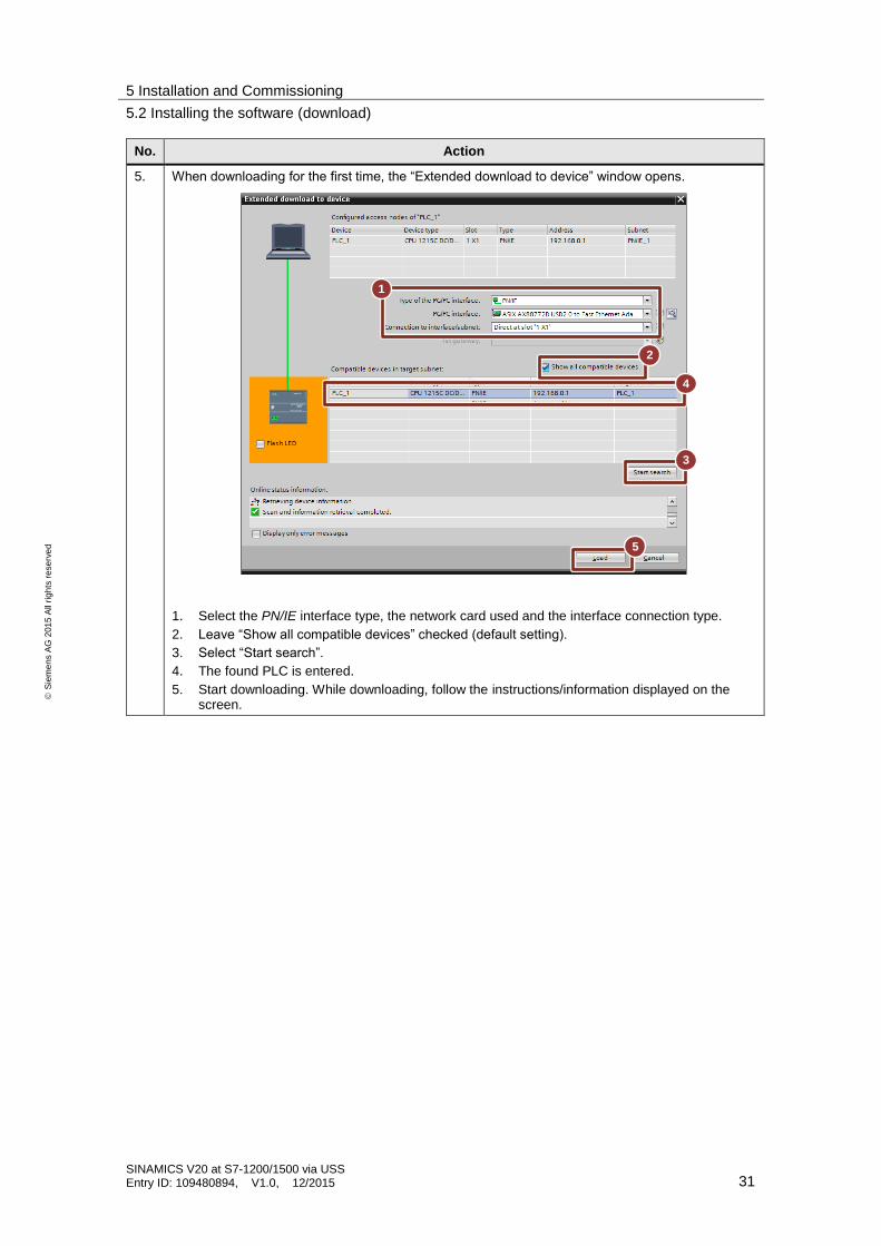
5. When downloading for the first time, the “Extended download to device” window opens.
1. Select the PN/IE interface type, the network card used and the interface connection type.
2. Leave “Show all compatible devices” checked (default setting).
3. Select “Start search”.
4. The found PLC is entered.
5. Start downloading. While downloading, follow the instructions/information displayed on the screen.
5
3
4
2
1
5 Installation and Commissioning
5.3 Commissioning
SINAMICS V20 at S7-1200/1500 via USS Entry ID: 109480894, V1.0, 12/2015 32
S
iem
en
s A
G 2
01
5 A
ll ri
gh
ts r
ese
rve
d
No. Action
KTP600
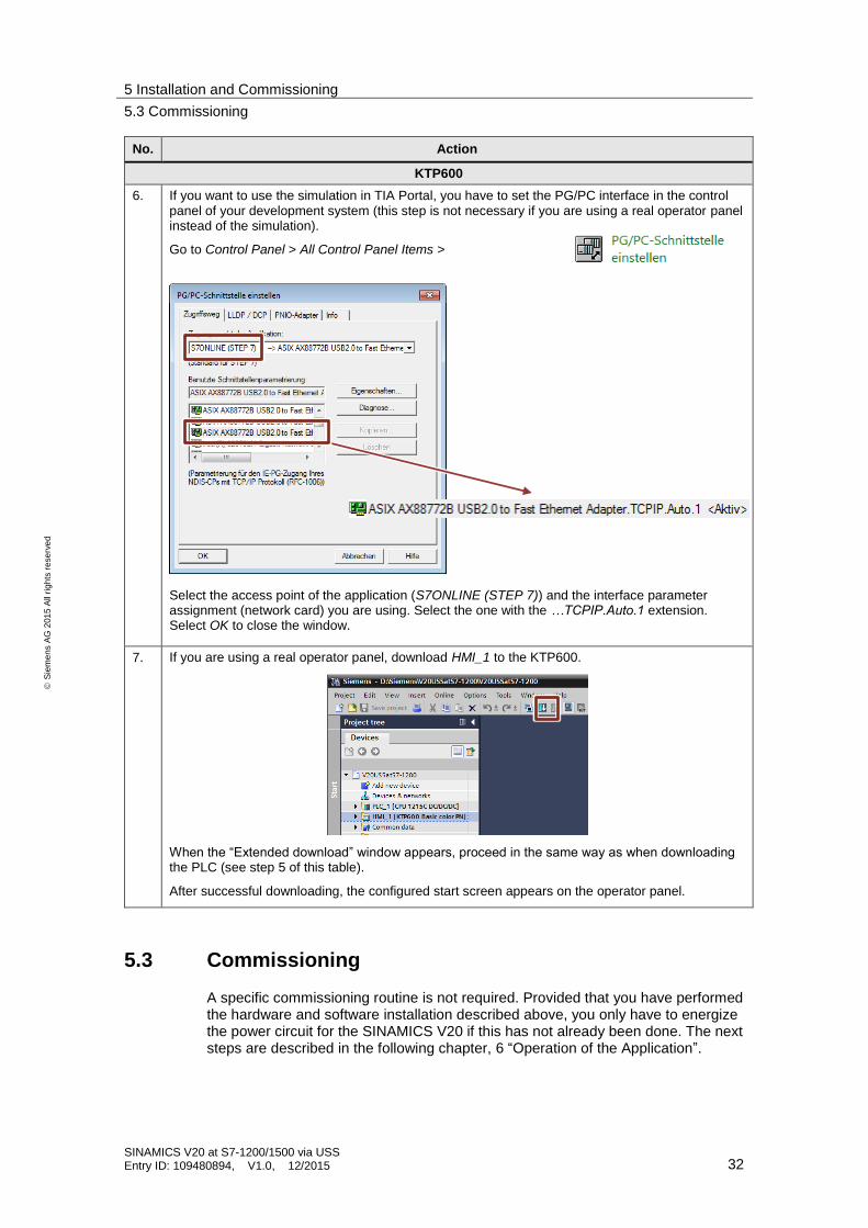
6. If you want to use the simulation in TIA Portal, you have to set the PG/PC interface in the control panel of your development system (this step is not necessary if you are using a real operator panel instead of the simulation).
Go to Control Panel > All Control Panel Items >
Select the access point of the application (S7ONLINE (STEP 7)) and the interface parameter assignment (network card) you are using. Select the one with the …TCPIP.Auto.1 extension. Select OK to close the window.
7. If you are using a real operator panel, download HMI_1 to the KTP600.
When the “Extended download” window appears, proceed in the same way as when downloading the PLC (see step 5 of this table).
After successful downloading, the configured start screen appears on the operator panel.
5.3 Commissioning
A specific commissioning routine is not required. Provided that you have performed the hardware and software installation described above, you only have to energize the power circuit for the SINAMICS V20 if this has not already been done. The next steps are described in the following chapter, 6 “Operation of the Application”.
6 Operation of the Application
6.1 Operator control using the HMI
SINAMICS V20 at S7-1200/1500 via USS Entry ID: 109480894, V1.0, 12/2015 33
S
iem
en
s A
G 2
01
5 A
ll ri
gh
ts r
ese
rve
d
6 Operation of the Application The application example is preferably operator controlled and monitored using the HMI (KTP600 or KTP600 simulation in TIA Portal). However, operator control is also possible online in TIA Portal using watch tables.
6.1 Operator control using the HMI
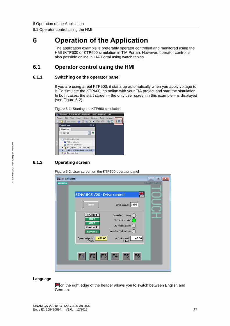
6.1.1 Switching on the operator panel
If you are using a real KTP600, it starts up automatically when you apply voltage to it. To simulate the KTP600, go online with your TIA project and start the simulation. In both cases, the start screen – the only user screen in this example – is displayed (see Figure 6-2).
Figure 6-1: Starting the KTP600 simulation
6.1.2 Operating screen
Figure 6-2: User screen on the KTP600 operator panel
Language
on the right edge of the header allows you to switch between English and German.
6 Operation of the Application
6.2 Operator control using the watch table
SINAMICS V20 at S7-1200/1500 via USS Entry ID: 109480894, V1.0, 12/2015 34
S
iem
en
s A
G 2
01
5 A
ll ri
gh
ts r
ese
rve
d
Control elements
The buttons displayed in the white frame on the operator panel, indicators and input/output fields correspond to the signals listed in chapter 1.2 “Operation of the drive”. An unpressed button is displayed in gray and represents the logical state false. A pressed button is displayed in green and represents the logical state true.
In the yellow input field, enter the speed setpoint as a percentage of the output frequency of the SINAMICS V20. The white output field displays the actual speed, also as a percentage of the output frequency.
Functions are not assigned to the six function keys below the screen; these keys have no function.
Default
Due to entered start values in the InstUssCyclic instance DB, the drive starts at 50% of its rated speed in forward direction only when pressing ON/OFF1.
Error display
If a communication error occurs, the top part of the screen displays the saved error status of the USS_PORT or USS_Port_Scan system FB. In this case, the Error button
flashes, which allows you to reset the error display.
6.2 Operator control using the watch table
Open the USSoperation watch table and go online.
Figure 6-3: Opening the USSoperation watch table
The tags in the watch table are identical to the ones on the operator panel. The only thing that differs is the representation of STW and ZSW; in contrast to the
operator panel, they are not represented bit by bit but word by word.
7 Expansion to multiple Slaves
7.1 Expansion to multiple slaves with S7-1200
SINAMICS V20 at S7-1200/1500 via USS Entry ID: 109480894, V1.0, 12/2015 35
S
iem
en
s A
G 2
01
5 A
ll ri
gh
ts r
ese
rve
d
7 Expansion to multiple Slaves
7.1 Expansion to multiple slaves with S7-1200
Expansion to multiple drives
The application example operates one SINAMICS V20. However, up to 16 drives can be operated via one port. To increase the number of drives, proceed as follows:
Table 7-1: Expansion to up to 16 drives for S7-1200
No. Instruction
1. Add the number of desired drives to your configuration as shown in Figure 5-2.
2. Follow no. 1 to 10 of Table 4-1 to parameterize the added inverters using the built-in BOP. From “2” onward, the drive addresses have to be assigned continuously.
3. Change the program so that the USS_DRV block is called for each drive. In this process, the appropriate address of the drive must be entered in the DRIVE input variable.
Expansion to multiple ports
You can provide the CPU with a maximum of three communication modules and one communication board. Up to 16 drives are possible on each module/board. In the section below, you will learn how to expand the application by a port.
Table 7-2: Port expansion for S7-1200
No. Instruction
Installing and wiring new hardware
1. As shown in Figure 5-2, add the drives to your configuration that are to communicate with the controller via the new, additional port.
2. Add a new CM1241 (RS485) communication module to the SIMATIC S7-1200 station or insert a CB1241 (RS485) communication board into the CPU.
3. Physically establish the USS bus connection between the new drives and the new port.
Parameterizing new drives using the BOP
4. Follow no. 1 to 10 of Table 4-1 to parameterize the added inverters using the built-in BOP. From “1” onward, the drive addresses have to be assigned continuously.
Device configuration in TIA Portal
5. In the device configuration, copy the existing communication module (1) and paste it directly to the left of it into slot 102 (2).
7 Expansion to multiple Slaves
7.1 Expansion to multiple slaves with S7-1200
SINAMICS V20 at S7-1200/1500 via USS Entry ID: 109480894, V1.0, 12/2015 36
S
iem
en
s A
G 2
01
5 A
ll ri
gh
ts r
ese
rve
d
No. Instruction
When using a different module type or the communication board (1), use drag and drop to move it from the catalog to the intended location in the workspace (2).
Configure the module/board pasted from the catalog. Change the transmission speed (38.4 kbit) and parity (even). All other default values do not need to be changed.
2
1
1 2
7 Expansion to multiple Slaves
7.2 Expansion to multiple slaves with S7-1500
SINAMICS V20 at S7-1200/1500 via USS Entry ID: 109480894, V1.0, 12/2015 37
S
iem
en
s A
G 2
01
5 A
ll ri
gh
ts r
ese
rve
d
No. Instruction
Program extension in TIA Portal
6. In the project tree, copy the code blocks ...
Cyclic_interrupt
UssCyclic
and the data block (in System blocks > Program resources) …
InstUssDrv
The copies are automatically created with index _1:
Cyclic_interrupt_1
UssCyclic_1
InstUssDrv_1
The name of the copied blocks can be changed in the block properties.
7. Open the Main OB (OB1). Now drag the copied block, UssCyclic_1, to a network and supply it with a new instance data block.
8. Open the newly created block UssCyclic_1. Now adjust the number of calls of USS_DRV in the block to the number of drives in the new communication module. For the remaining calls of USS_DRV, replace the instance data block and insert the InstUssDrv_1 data block.
9. Open the cyclic interrupt OB Cyclic_interrupt_1. Here the call of the UssCyclicInterrupt block can be retained. However, supply it with a new instance data block.
The hwIdentifier input must contain a reference to the new communication module.
In the USS_DB input, refer to the new data block, InstUssDrv_1.
10. Compile the entire STEP7 program.
7.2 Expansion to multiple slaves with S7-1500
Expansion to multiple drives
The application example operates one SINAMICS V20. However, up to 16 drives can be operated via one port. To increase the number of drives, proceed as follows:
Table 7-3: Expansion to up to 16 drives for S7-1500
No. Instruction
1. Add the number of desired drives to your configuration as shown in Figure 5-2.
2. Follow no. 1 to 10 of Table 4-1 to parameterize the added inverters using the built-in BOP. From “2” onward, the drive addresses have to be assigned continuously.
3. Change the program so that the USS_Drive_Control block is called for each
drive. In this process, the appropriate address of the drive must be entered in the DRIVE input variable.
Expansion to multiple ports
You can provide the CPU with more communication modules. Up to 16 drives are possible on each module. In the section below, you will learn how to expand the application by a port.
7 Expansion to multiple Slaves
7.2 Expansion to multiple slaves with S7-1500
SINAMICS V20 at S7-1200/1500 via USS Entry ID: 109480894, V1.0, 12/2015 38
S
iem
en
s A
G 2
01
5 A
ll ri
gh
ts r
ese
rve
d
Table 7-4: Port expansion for S7-1500
No. Instruction
Installing and wiring new hardware
1. As shown in Figure 5-2, add the drives to your configuration that are to communicate with the controller via the new, additional port.
2. Add a new CM PtP RS422/485 communication module to the SIMATIC S7-1500 station.
3. Physically establish the USS bus connection between the drives and the new port.
Parameterizing new drives using the BOP
4. Follow no. 1 to 10 of Table 4-1 to parameterize the added inverters using the built-in BOP. From “1” onward, the drive addresses have to be assigned continuously.
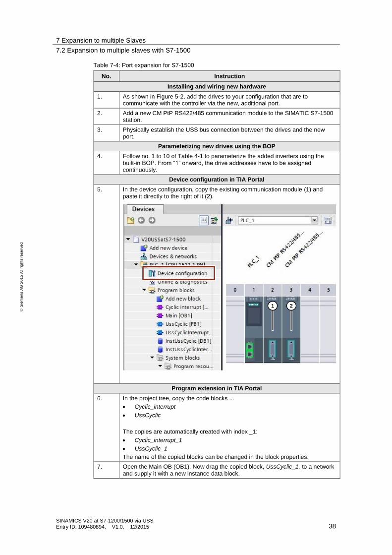
Device configuration in TIA Portal
5. In the device configuration, copy the existing communication module (1) and paste it directly to the right of it (2).
Program extension in TIA Portal
6. In the project tree, copy the code blocks ...
Cyclic_interrupt
UssCyclic
The copies are automatically created with index _1:
Cyclic_interrupt_1
UssCyclic_1
The name of the copied blocks can be changed in the block properties.
7. Open the Main OB (OB1). Now drag the copied block, UssCyclic_1, to a network and supply it with a new instance data block.
1 2
7 Expansion to multiple Slaves
7.2 Expansion to multiple slaves with S7-1500
SINAMICS V20 at S7-1200/1500 via USS Entry ID: 109480894, V1.0, 12/2015 39
S
iem
en
s A
G 2
01
5 A
ll ri
gh
ts r
ese
rve
d
No. Instruction
8. Open the newly created block UssCyclic_1. Now adjust the number of calls of USS_Drive_Control in the block to the number of drives in the new communication module. For the remaining calls of USS_Drive_Control, replace the instance.
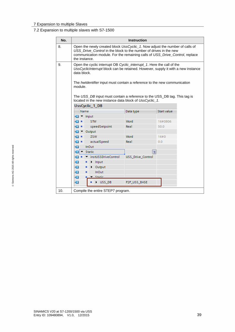
9. Open the cyclic interrupt OB Cyclic_interrupt_1. Here the call of the UssCyclicInterrupt block can be retained. However, supply it with a new instance data block.
The hwIdentifier input must contain a reference to the new communication module.
The USS_DB input must contain a reference to the USS_DB tag. This tag is located in the new instance data block of UssCyclic_1.
10. Compile the entire STEP7 program.
8 Links & Literature
SINAMICS V20 at S7-1200/1500 via USS Entry ID: 109480894, V1.0, 12/2015 40