32
Application Guide M-2280B Adapter Panel

Application Guide
M-2280BAdapter Panel

Adapter PanelM-2280B
CONTROLS
Adapts M-2001 Series Digital Tapchanger Control as aReplacement for General Electric Static LTC Transformerand Regulator Controls and some Balance Beam Models
• Connects easily to the M-2001 Series Digital TapchangerControl using mounting screws and 24-pin connector
• Provides direct mechanical replacement of the existing control
• Provides built-in CT shorting protection when theM-2001 Series Digital Tapchanger Control is removed
• Optional SCADA Cutout (Local/Remote) switch (for use withSCADA enabled M-2001C controls) allows Local Blockingof SCADA commands
• Optional SCAMPTM (SCADA Controllable Auto/Manual Pushbutton)switch replaced AUTO/OFF/MANUAL toggle switch
• Optional 2 Level Local Voltage Reduction Switch

–2–
M-2280B Adapter Panel
The M-2280B is an adapter panel which, when combined with the M-2001 Series Digital Tapchanger Control,provides convenient direct replacement for General Electric static LTC transformer and regulator controlsand some balance beam models.
InterfaceExternal connections are made to a terminal block located on the top of the rear panel of the M-2280B.Additional connections may be made to two terminal blocks located on the printed circuit board of theadapter panel. These terminal blocks provide access to auxiliary functions, including self-test alarm, user-programmable alarm, auto disable and manual raise/lower.
FeaturesSeparate fuses for test terminal, voltage sensing and motor power are located on the front panel. Sparefuses for each are in the fuse holder.
Binding posts on the front panel allow easy connections for test procedures.
RAISE/OFF/LOWER, AUTO/OFF/MANUAL and VOLTAGE SOURCE switches, DRAG HANDS RESETbutton, and NEUTRAL LIGHT are standard.
NEUTRAL LIGHT will light to indicate that the regulator is in the neutral position, for those productsequipped with a circuit for this purpose.
OptionsSCADA CUTOUT switch allows Local blocking of SCADA commands (for use with SCADA enabled M-2001Ccontrols). The SCADA Cutout switch must be used with a M-2001 Series Control with firmware versionD-0146V08.01.22 or later installed.
SCAMPTM (AUTO/MANUAL) pushbutton switch allows the Auto/Manual state on the adapter panel to bechanged by a SCADA command. The SCAMP pushbutton switch must be used with a M-2001 Series Controlwith firmware version D-0146V08.05.XX or later installed.
Voltage Reduction switch allows 2 levels of Voltage Reduction to be selected.
Testing SpecificationsHigh Voltage: All input and output terminals will withstand 1500 V ac rms to chassis or instrument groundfor one minute with a leakage current not to exceed 25 mA, for all terminals to ground. Input and outputcircuits are electrically isolated from each other, from other circuits and from ground.
Surge Withstand Capability: All input and output circuits are protected against system transients. Unitspass all requirements of ANSI/IEEE C.37.90.1-1989 defining surge withstand capability.
Radiated Electromagnetic Withstand Capability: All units are protected against electromagnetic radiatedinterference from portable communications transceivers.
EnvironmentalTemperature Range: Functionality is maintained from –40° to +85° C.
Humidity: Functionality is maintained under 95% relative humidity (non-condensing).
Fungus Resistance: A conformal printed circuit board coating inhibits fungus growth.

–3–
M-2280B Adapter Panel
PhysicalSize: 13-7/8" high x 12-7/8" wide x 5" deep (35.2 cm x 32.7 cm x 12.7 cm)
Mounting: 11" high x 8" wide (27.9 cm x 20.3 cm) 4-hole pattern for surface mounting
Approximate Weight: 6 lbs, 3 oz (2.8 kg)
Approximate Shipping Weight: 8 lbs, 3 oz (3.7 kg)
Approximate Weight with M-2001 Series Digital Tapchanger Control: 10 lbs, 8 oz (4.8 kg)
Approximate Shipping Weight with M-2001 Series Digital Tapchanger Control: 14 lbs, 3 oz (6.44 kg)
WarrantyThe M-2280B Adapter Panel is covered by a five year warranty from date of shipment.
Specification subject to change without notice.

800-2280B-SP-04 09/13© 2008 Beckwith Electric Co. All Rights Reserved.Printed in USA

��������������� ������������������������������� ��!���!������"�!#���!���!���������� ���$��!������!%������������������ ���&���'%���(�����$�!�%�������������������)����������#�!�����) ��� ��'����������������!���"�������� ���&���%���(�*�)�+�!��� ��������!���+���������+�����!������!����!�� ���� ��+�������������������� ���$��!'������!%�����(
DANGER! HIGH VOLTAGE
– This sign warns that the area is connected to a dangerous high voltage, and youmust never touch it.
PERSONNEL SAFETY PRECAUTIONSThe following general rules and other specific warnings throughout the manual must be followed during application,test or repair of this equipment. Failure to do so will violate standards for safety in the design, manufacture, and intendeduse of the product. Qualified personnel should be the only ones who operate and maintain this equipment. BeckwithElectric Co., Inc. assumes no liability for the customer’s failure to comply with these requirements.
– This sign means that you should refer to the corresponding section of the operation
manual for important information before proceeding.
Always Ground the Equipment
To avoid possible shock hazard, the chassis must be connected to an electrical ground. When servicingequipment in a test area, the Protective Earth Terminal must be attached to a separate ground securelyby use of a tool, since it is not grounded by external connectors.
Do NOT operate in an explosive environmentDo not operate this equipment in the presence of flammable or explosive gases or fumes. To do so wouldrisk a possible fire or explosion.
Keep away from live circuitsOperating personnel must not remove the cover or expose the printed circuit board while power is ap-plied. In no case may components be replaced with power applied. In some instances, dangerous volt-ages may exist even when power is disconnected. To avoid electrical shock, always disconnect power anddischarge circuits before working on the unit.
Exercise care during installation, operation, & maintenance proceduresThe equipment described in this manual contains voltages high enough to cause serious injury or death.Only qualified personnel should install, operate, test, and maintain this equipment. Be sure that all per-sonnel safety procedures are carefully followed. Exercise due care when operating or servicing alone.
Do not modify equipmentDo not perform any unauthorized modifications on this instrument. Return of the unit to a BeckwithElectric repair facility is preferred. If authorized modifications are to be attempted, be sure to followreplacement procedures carefully to assure that safety features are maintained.

PRODUCT CAUTIONSBefore attempting any test, calibration, or maintenance procedure, personnel must be completely familiarwith the particular circuitry of this unit, and have an adequate understanding of field effect devices. If acomponent is found to be defective, always follow replacement procedures carefully to that assure safetyfeatures are maintained. Always replace components with those of equal or better quality as shown in theParts List of the Instruction Book.
Avoid static chargeThis unit contains MOS circuitry, which can be damaged by improper test or rework procedures. Careshould be taken to avoid static charge on work surfaces and service personnel.
Use caution when measuring resistancesAny attempt to measure resistances between points on the printed circuit board, unless otherwise notedin the Instruction Book, is likely to cause damage to the unit.

1.0 Introduction ....................................................................................................................... 1
1.1 Description ........................................................................................................................ 1Standard Features ............................................................................................................ 1Control Switches ............................................................................................................... 1Binding Posts ................................................................................................................... 1Status Indicators .............................................................................................................. 2Optional Control Switches ................................................................................................ 2
2.0 Application ........................................................................................................................ 2External Connections ....................................................................................................... 2Lightning Protection .......................................................................................................... 2Neutral Light Circuit .......................................................................................................... 2Non-Sequential Operation (N/A for BASE-R Version) ..................................................... 2Automatic Disable Input ................................................................................................... 3Operations Counter Input ................................................................................................. 3Local/Remote Input .......................................................................................................... 3Multi-Step Voltage Reduction ........................................................................................... 3Paralleling (N/A for BASE-RS and BASE-R Controls) ..................................................... 3Disabling Auto/Off/Manual Toggle Switch Status Detection ........................................... 3Operations Counter Input ................................................................................................. 4Connections for General Electric LTC Transformers ....................................................... 4Table 1 Multi-Step Voltage Reduction External Connections ....................................... 4Use of the M-0329B LTC Backup Control with the Tapchanger Control ......................... 4Figure 1 External Connections ....................................................................................... 5Figure 2 M-2001C and M-2280B Adapter Panel with Standard Auto/Off/ManualToggle Switch and Optional Voltage Reduction and SCADA Cutout Switches ............... 6Figure 3 M-2001C and M-2280B Adapter Panel with optional SCAMPTM Auto/ManualPushbutton switch SCADA Cutout switch and Voltage Reduction switch ...................... 7Figure 4 M-2280B Wiring Harness and External Connections ...................................... 8Figure 5 M-2280B Wiring Harness with optional SCAMPTM Auto/Manual Pushbuttonswitch, SCADA Cutout switch and Voltage Reduction switch ........................................ 9Figure 6 Tapchanger Control and LTC Backup Control Interconnections ................... 10
TABLE OF CONTENTSM-2280B ADAPTER PANEL
Application Guide
© 2006 Beckwith Electric Co.Printed in USA
800‑2280B‑AG‑04MC2 04/15
3.0 Installation ........................................................................................................................ 11 Removal of the Control ...............................................................................................11 Installing the M-2280B/M-2001 ...................................................................................11 Figure 7 M-2001 Harness Connector .......................................................................11 Figure 8 M-2001 V-Notch Orientation .......................................................................11 Installation of the M-2280B Adapter Panel ..................................................................11 Figure 9 Outline Dimensions ....................................................................................12 Figure 10 M-2280B Hole Drill Dimensions ................................................................13
4.0 M-2001 Tapchanger Control Software Settings ................................................................ 14
4.1 M-0329B LTC Backup Control Settings ............................................................................ 14
5.0 Bench Test (M-2001 Connected to M-2280B) .............................................................15 Test Equipment ...........................................................................................................15 Setup ..........................................................................................................................15 Table 2 Initial Settings ..............................................................................................15 Procedure ...................................................................................................................15 Resistance ..................................................................................................................15 Figure 11 M-2280B Test Procedure External Connection ..........................................16 Reactance ..................................................................................................................17 Paralleling ...................................................................................................................17 Voltage Source Switch ................................................................................................17 Drag Hands Reset ......................................................................................................17 Counter/Neutral Light/Tap Position .............................................................................17 Block Raise/Block Lower/Dead Band ..........................................................................17
5.1 M-2001 Checkout Procedure ......................................................................................18 Basic Operational Test ................................................................................................18
5.2 In-Service Test ............................................................................................................18
5.3 M-2280B Checkout Procedures ..................................................................................18 Power .........................................................................................................................18 Figure 12 Setup for Current Checkout Procedure ....................................................19

-1-
M-2280B Application Guide
1.0 Introduction
The Beckwith Electric M-2280B Adapter Panel, usedin conjunction with the M-2001 Tapchanger Control,uses modern electronic digital design and digitalprocessing circuitry to achieve an overall stabilityand resolution unattainable with electromechanicaland analog design tapchanger controls. CMOSsemiconductors are used throughout the design.
1.1 Description
Standard FeaturesThe M-2280B Adapter Panel, with the M-2001Tapchanger Control, provides a solid-state voltagecontrol relay designed to replace General Electricstatic LTC transformer controls and some balancebeam models. The combination of the TapchangerControl and Adapter Panel includes the followingfeatures:
• Voltage waveform sampling and digitalprocessing circuitry ensure accurate rmsvoltage sensing in the presence ofdistortion on the input voltage and current.
• Control accuracy is 0.3 % when testedin accordance with the ANSI/IEEEC57.15.9-1999 standard over atemperature range of –30° C to +65° C.The control accuracy is 0.5 % whentested over the full operational temperaturerange of –40° C to +85° C.
• Input and output circuits are protectedagainst system transients. Units passall requirements of ANSI/IEEEC37.90.1-1989, which defines surgewithstand capability. All input and outputterminals will withstand 1500 V ac rms tochassis or instrument ground for oneminute with a leakage current not to exceed25 mA, for all terminals to ground. Inputand output circuits are electrically isolatedfrom each other, from other circuits andfrom ground.
The M-2280B Adapter Panel factory configuration forAUTO/OFF/MANUAL switch status detection isEnabled. The M-2280B Adapter Panel AUTO/OFF/MANUAL switch status detection feature is availableto M-2001 series units that have Firmware VersionD-0067V07.08.15 or later installed. See Section 2.0,Application, Disabling Auto/Off/Manual SwitchStatus Detection, for the steps necessary to disable
the AUTO/OFF/MANUAL switch detection functionfor M-2001 series units with an earlier firmware version.
Control SwitchesRAISE/LOWER/OFF switch allows local manualraise and lower commands to be initiated
AUTO/OFF/MANUAL switch allows auto operationof the control or manual operation from the panel byusing the Raise/Lower toggle switch. The AUTO/OFF/MANUAL switch status may be read by aM-2001 series control with firmware versionD-0067V07.08.15 or later installed.
When the M-2001C Input Selection 1 screen in theConfiguration menu is set to Switch Status Input,the seal-in input will operate as a switch statusinput. All seal-in input functions will be disabled. Inthis mode, the switch status on the adapter panelcan be read to determine if it is in Auto or Manual.The status can be read through the seal-in/switchstatus data point in the communications protocols.
VOLTAGE SOURCE switch in the EXT positiondisconnects the voltage transformer input andconnects the EXTERNAL POWER binding posts tothe voltage input and motor circuit.
The unit can be tested using an external 120 VRMS source of proper polarity applied to theseterminals. Testing can be accomplished by adjustingthe amplitude of the external source.
DRAG HANDS RESET pushbutton resets thetapchanger position indicator drag hands.
Binding Posts▲ CAUTION: Do not reverse the ground and hotwires when connecting an external source. A 3 AGfuse (F2) is installed to protect the control from damageif these connections are accidentally reversed.
• VOLTAGE IN binding posts on the frontpanel allow application of a 120 V rmsnominal voltage to the unit for testprocedures.
• MOTOR PWR IN binding posts on thefront panel allow application of a 120 or240 V rms nominal voltage to the unit fortest procedures.
NOTE: If the Motor Power Input configuration hasa different return from the 120 V regulatedVoltage Input, then Jumper J12 on theprinted circuit board must be removed andTB1-16 should be used for the separatemotor power source and return connections(See Figures 4 and 5 for J12 location).

-2-
M-2280B Application Guide
• METER OUT binding posts on the frontpanel allow reading of the input voltagewhen used in conjunction with the BIASTEST VOLTAGE screen of the M-2001Tapchanger Control.
Status IndicatorsNEUTRAL light illuminates when the regulator is inthe neutral tap position.
The Adapter Panel includes three replaceable fuses:Test Terminal (3 A), Voltage Sense (1 A), andMotor Power (6 A).
Optional Control SwitchesVOLTAGE REDUCTION (VR1/OFF/VR2) switchallows local voltage reduction 1 or 2 to be initiated.
SCADA CUTOUT (LOCAL/REMOTE) switch allowsthe local blocking of SCADA commands. TheSCADA Cutout switch must be used with a M-2001Series Control with firmware versionD-0146V08.01.22 or later installed.
SCAMPTM (AUTO/MANUAL) pushbutton switchallows the Auto/Manual state on the adapter panelto be changed by a SCADA command. The SCAMPpushbutton switch must be used with a M-2001Series Control with firmware versionD-0146V08.05.XX or later installed.
2.0 Application
External ConnectionsPower and voltage sensing are obtained either froma common source or from independent sourceshaving a nominal 120 V ac output. Normally, this isline-to-neutral voltage, although line-to-line voltagecan also be used if recognition is made of anyphase shift between the voltage and current signalswhen using line drop compensation.
Load current must be reduced by an appropriateauxiliary current transformer to 0.2 A “full scale”before connecting to the M-2280B current inputs.The Beckwith Electric M-0121 (5.0 A to 0.2 A) orM-0169A (5.0 A or 8.66 A to 0.2 A) Auxiliary CurrentTransformer can be used for this purpose. TheM-0121 can be used with Beckwith ElectricTapchanger Controls when the only burden presentis the Line Drop Compensator circuit of the voltageregulating relay. The M-0169A is used in higherburden circuits, such as are found in parallelingschemes. Outputs of the auxiliary CTs are protected
against overvoltage. For further information, obtainBeckwith Electric Application Note #17, “BasicConsiderations for the Application of LTCTransformers and Associated Controls.”
The external connections for the M-2280B are madeto terminal block TB3 located at the top of theadapter panel. Auxiliary external connections, ifneeded, are made to terminal blocks TB1 and TB2on the printed circuit board at the base of the adapterpanel. The wiring harness and external connectionsfor the M-2280B are shown in Figures 4 and 5.
Lightning Protection▲ CAUTION: For proper protection against systemsurges, chassis ground must be connected to earthground.
It has been determined that transient voltages inexcess of 1500 V ac RMS can exist on the “ground”lead normally tied to TB1-8. In the tapchangercontrols, these voltages are suppressed by varistorswhich still permit the unit to pass a 1500 V ac hi-pottest for one minute, with a leakage of approximately15 mA, all terminals to ground.
Multiple VT grounds far apart must be avoided,since a varying difference in ground voltage couldadd or subtract from the effective voltage, andcause variation in the tapchanger control’sbandcenter voltage setpoint.
Neutral Light CircuitIf the Neutral Light terminal TB3-14 needs to begrounded for the light to illuminate, set switch S1(located in the right-hand corner of the adapter panelprinted circuit board) to the toggle up position. If theNeutral Light terminal TB3-14 needs to be poweredfor the light to illuminate, set switch S1 (located inthe right-hand corner of the adapter panel printedcircuit board) to the toggle down position.
Non-Sequential Operation (N/A for BASE-RVersion)The operation of the M-2280B can be interruptedduring tapchanger operation by momentarily applyingthe “wetting” voltage of terminal TB2-28 to TB3-15(timer reset for non-sequential operation input)through an external contact. This causes the outputto de-energize and reinitialize the time delay circuitwhen the reset signal is removed. This function canbe used to cause the LTC transformer, if soequipped, to wait for the unit to time out betweentapchanges.

-3-
M-2280B Application Guide
▲ CAUTION: Voltage applied through dry contactsto actuate non-sequential input must be nominal+12 V dc obtained from pin TB2-28 of the M-2280Badapter panel. If an M-0280 analog-versiontapchanger control had previously been installed,the wiring harness must be reconfigured to removethe 120 V ac “wetting” voltage obtained from TB1-9located on the top of the rear panel of the M-0280.Carefully examine the contacts of these functionsto remove 120 V ac wetting voltages.
Automatic Disable InputTo disable automatic operation of the M-2280B,remove Jumper #15 (See Figures 4 and 5, forlocation) on the printed circuit board.
If SCADA is used to enable and disable thisfunction, a contact rated at 6 A minimum can beconnected between the terminals.
Auto disable may also be accomplished by closinga contact between TB1-1 and TB2-28.
Operations Counter Input▲ CAUTION: Do not apply any voltage to thisterminal.
An operations count is registered by momentarilygrounding TB1-13 through an external dry contactfrom the load tapchanger. The input is level-sensitive.Make sure that any “wetting” voltages are removedfrom the counter contacts before installing theM-2280B Adapter Panel/M-2001 Tapchanger Control.
Local/Remote InputRemoving Jumper #14 (See Figures 4 and 5, forlocation) prohibits M-2001 operation by disablingthe automatic raise and lower outputs and also bydisabling the M-2280B Adapter Panel’s manualRAISE/OFF/LOWER toggle switch. Removing thisjumper does not disable the SCADA-supplied motorvoltage input to the manual raise/manual lowercontacts on the adapter panel.
Multi-Step Voltage ReductionOn the M-2280B, TB3-10 and TB3-11 at the top ofthe adapter panel are used together to provide up tothree levels of voltage reduction. The externalconnections to achieve these steps are shown inTable 1 and Figure 1. Voltage reduction amounts areset within the M-2001 Tapchanger Control software.
▲ CAUTION: Voltage applied through dry contactsto actuate Voltage Reduction Steps 1, 2, and 3 mustbe nominal +12 V dc obtained from pin TB2-28 of theM-2280B adapter panel. If an M-0280 analog-versiontapchanger control had previously been installed, thewiring harness must be reconfigured to remove the120 V ac “wetting” voltage obtained from TB1-9located on the top of the rear panel of the M-0280.Carefully examine the contacts of these functions toremove 120 V ac wetting voltages.
Paralleling (N/A for BASE-RS and BASE-RControls)See M-2001C Instruction Book, Section 4.9, ParallelOperation.
Disabling Auto/Off/Manual Toggle SwitchStatus DetectionThe Auto/Off/Manual Toggle Switch status detectionfeature is available on M-2001 Series DigitalTapchanger Controls that have Firmware VersionD-0067V07.08.15 or later installed. To disable theAuto/Off/Manual Toggle Switch status detectionfeature for earlier firmware versions, perform thefollowing:
1. Ensure that all power is removed from theM-2280B Adapter Panel and M-2001 control.
2. From the rear of the M-2280B Adapter Panellocate (Figures 4 and 5) and remove thewire connected to Terminal S3-4 on therear of the AUTO/OFF/MANUAL toggleswitch.
3. Connect the wire removed in Step 2 toTerminal S2-4 on the rear of the RAISE/OFF/LOWER switch.
4. See M-2001 Instruction Book Section 6.1,External Connections, for informationregarding M-2001 settings to disable thisfunction.

-4-
M-2280B Application Guide
Operations Counter Input▲ CAUTION: Do not apply either +12 V dc or 120 Vac to this terminal.
An operations count is registered by momentarilygrounding TB3-12 through an external dry contactfrom the load tapchanger. The input is level-sensitive.Make sure that any “wetting” voltages are removedfrom the counter contacts before installing theM-2280B Adapter Panel/M-2001 Tapchanger Control.
Connections for General Electric LTCTransformersIn general, the tapchanger motor must be operatedfrom a different transformer than the VT used tomeasure regulated voltage. If this is not done,hunting at the upper band edge may result.
A typical connection for an M-2280B is shown inFigure 2. Connections are simplified and may notshow all functions required in a typical loadtapchanging transformer control scheme; forexample, seal-in contacts, limit switches, etc.
Voltage Reduction Setpoint:Multiplier Range
Apply "Wetting Voltage"from TB2-28 to Terminal #
Voltage Reduction Setpoint #1: 0 to 10% TB3-10
Voltage Reduction Setpoint #2: 0 to 10% TB3-11
Voltage Reduction Setpoint #3: 0 to 10% TB3-10 and TB3-11
Table 1 Multi-Step Voltage Reduction External Connections
Use of the M-0329B LTC Backup Control withthe Tapchanger ControlThe M-0329B is a single-phase, solid-state backupcontrol that prevents a defective tapchanger controlfrom running the voltage outside the upper andlower voltage limits. The Block Raise and BlockLower voltage levels are set by accurately calibrateddials.
The M-0329B LTC Backup Control is connected asa two terminal device to the voltage transformer.Figure 4 shows the typical interconnection of thetwo devices with motor auxiliary relays.
The M-0329B Instruction Book is available on requestand gives added details. Please refer to the M-0329BInstruction Book for complete ordering information.

-5-
M-2280B Application Guide
1
2
3
4
5
6
7
8
9
10
11
12
13
14
15
17
18
19
20
21
22
23
24
25
26
27
28
TB216
TB1
Manual Lower
Manual Raise
Motor Seal-In Input
Self-Test Alarm(Return)
Self-Test Alarm(Polarity)
User-ProgrammableAlarm (Return)
+12 V dc Wetting Supply
User-ProgrammableAlarm (Polarity)
Auto Disable
Local/Remote
Motor PowerReturn
Circulating Current(Return)
Circulating Current(Polarity)
Tapchanger RaiseOutput
Tapchanger LowerOutput
Non-Sequential / AutoTapchange Inhibit Input
Voltage ReductionStep #2 Input
Voltage ReductionStep #1 Input
Neutral
Motor Power 120/240 V ac Supply
Regulated Voltage(120 V ac)
Neutral Light
Drag Hands Reset
OperationsCounter Input
Line Current(Polarity)
Line Current(Return)
xx
YY
GE Terminals
M-2280BTerminals
1
2
3
4
5
6
7
8
9
10
11
12
13
14
15
TB3
ToParalleling
UnitN14
N13
Motor
L RN8
N7
Volt ReductionStep #1 Contact
Voltage ReductionStep #2 Contact
Non-Sequential / AutoTapchange Inhibit Input
Neutral(Grd Stud)(Motor Return)
N6
N1 Voltage In(Reg 120 V)
Neutral LightSwitch
PositionIndicator Reset
OperationsCounter Switch
N2
N3CTLine
Current
CT ShortingSwitch
N4 Motor
Remove jumperto isolate thereturn side ofthe line current
(Note 2)
88888 WARNING: Open CT secondary will result in high voltage at CT terminals. Death, severe injury ordamage to equipment can occur. Do not operate with CT secondary open. Short circuit or applyburden at CT secondary during operation.
■ NOTES: 1. External connections are made to TB3 located at the top of the adapter panel. Auxiliaryexternal connections may be made to TB1 and TB2 as needed.
2. If the Motor Power Input configuration has a different return from the 120 V regulated VoltageInput, then Jumper J12 on the printed circuit board must be removed and TB1-16 should be used forthe separate motor power source and return connections (See Figures 4 and 5 for J12 location).
Figure 1 External Connections

-6-
M-2280B Application Guide
1
2
3
4
5
6
7
8
9
10
11
12
13
14
15
17
18
19
20
21
22
23
24
25
26
27
28
TB2
M-20011
2
3
4
5
6
7
8
9
10
11
12
13
14
15
16
17
18
19
20
21
22
23
24
Voltage Input(Polarity)
Load Current(Return)
Neutral
Load Current(Polarity)
Circulating Current(Polarity)
Circulating Current(Return)
Tapchanger RaiseOutput
Motor Power Input
Voltage ReductionStep #2 Input
Contact "Wetting"Supply +12 V dc
Operation CounterInput #1
Operation CounterInput #2
Motor Seal-InDetector Input
Neutral PositionDetector #1
Neutral PositionDetector #2
Tapchanger LowerOutputNon-SequentialOperation/Auto T.C.Inhibit InputVoltage ReductionStep #1 Input
Motor Seal-InDisconnect Output
User-ProgrammableAlarm
Self-Test Alarm
User-ProgrammableAlarm
Non-InterruptablePower Supply Input
Self-Test Alarm
INT
OFF
EXT
INT
OFF
EXT
MeterOut
(Front Panel Inputs) TestTerminalFuse 3 A
Drag HandsReset
NeutralLight
Voltage InFuse (1 A)
Motor PowerFuse (6 A)
Up(Netrual)
Down(Hot)
S1
ManualRaise
ManualLower
OFF(Momentary) Manual
AutoOFF
AutoOFF
Manual
R51 K Ohm
16
J12
J4
J5
J14
J15
RT1(.150 A)
VoltageIn
Manual Lower
Manual Raise
Motor Seal-In Input
Self-Test Alarm(Return)
Self-Test Alarm(Polarity)
User-ProgrammableAlarm (Return)
+12 V dc Wetting Supply
User-ProgrammableAlarm (Polarity)
AutoDisable
Local/Remote
TB115
11
8
9
6
7
10
5
4
1
14
13
12
3
2
TB3
Local
Remote
SCADACutout
Optional
VR1
VR2
VoltageReductionOFF
MotorPower
xx
YY
GE Terminals
M-2280BTerminals
Motor PowerReturn
Circulating Current(Return)
Circulating Current(Polarity)
Tapchanger RaiseOutput
Tapchanger LowerOutput
Non-Sequential / AutoTapchange Inhibit Input
Voltage ReductionStep #2 Input
Voltage ReductionStep #1 Input
Neutral
Motor Power 120/240 V ac Supply
Regulated Voltage(120 V ac)
Neutral Light
Drag Hands Reset
OperationsCounter Input
Line Current(Polarity)
Line Current(Return)
Optional
Remove jumperto isolate thereturn side ofthe line current
8 WARNING: In no case should the line current circuit be interrupted with the regulator or transformerenergized. Do not remove auxiliary current transformers without shorting the current inputs. Death orsevere electrical shock can occur.
Figure 2 M-2001C and M-2280B Adapter Panel with Standard Auto/Off/Manual Toggle Switchand Optional Voltage Reduction and SCADA Cutout Switches

‑7‑
M-2280B Application Guide
Manual Lower
1
2
3
4
5
6
7
8
9
10
11
12
13
14
15
17
18
19
20
21
22
23
24
25
26
27
28
TB1
TB2
Manual Raise
Motor Seal-In Input
User-ProgrammableAlarm (Return)
+12 V dcWetting Supply
User-ProgrammableAlarm (Polarity)
Auto Disable
Local/Remote
M-20011
2
3
4
5
6
7
8
9
10
11
12
13
14
15
16
17
18
19
20
21
22
23
24
Voltage Input(Polarity)
Load Current(Return)
Neutral
Load Current(Polarity)
Circulating Current(Polarity)
Circulating Current(Return)
Tapchanger RaiseOutput
Motor Power Input
Voltage ReductionStep #2 Input
Contact "Wetting"Supply +12 V dc
Operation CounterInput #1
Operation CounterInput #2
Motor Seal-InDetector Input
Neutral PositionDetector #1
Neutral PositionDetector #2
Tapchanger LowerOutputNon-SequentialOperation/Auto T.C.Inhibit InputVoltage ReductionStep #1 Input
Motor Seal-InDisconnect Output
User-ProgrammableAlarm
Self-Test Alarm
User-ProgrammableAlarm
Non-InterruptablePower Supply Input
Self-Test Alarm
INT
OFF
EXT
INT
OFF
EXT
MeterOut
ExternalPower
(Front Panel Inputs) TestTerminalFuse 3 A
Drag HandsReset
NeutralLight
Voltage InFuse (1 A)
Motor PowerFuse (6 A)
ManualRaise
ManualLower
OFF(Momentary)
R51 K Ohm
16
Local
Remote
SCADACutout
J12
J4
J5
VR1
VR2
VoltageReductionOFF
Optional
Optional
J14
J15
RT1(.150 A)
Up(Netrual)
Down(Hot)
S1MotorPwr In
SCAMPAuto/Manual
Optional
15
11
8
9
6
7
10
5
4
1
14
13
12
3
2
TB3
Motor PowerReturn
Circulating Current(Return)
Circulating Current(Polarity)
Tapchanger RaiseOutput
Tapchanger LowerOutput
Non-Sequential / AutoTapchange Inhibit Input
Voltage ReductionStep #2 Input
Voltage ReductionStep #1 Input
Neutral
Motor Power 120/240 V ac Supply
Regulated Voltage(120 V ac)
Neutral Light
Drag Hands Reset
OperationsCounter Input
Line Current(Polarity)
Line Current(Return)
Remove jumper toisolate the return sideof the line current
xx
YY
GE Terminals
M-2280BTerminals
8 WARNING: In no case should the line current circuit be interrupted with the regulator or trans‑former energized. Do not remove auxiliary current transformers without shorting the current inputs. Death or severe electrical shock can occur.
Figure 3 M-2001C and M-2280B Adapter Panel with Optional SCAMPTM Auto/Manual Pushbutton Switch SCADA Cutout Switch and Voltage Reduction Switch

-8-
M-2280B Application Guide
TO TB
3
F2F42 F3
BP3
BP2
S4
BP1
RB
S3
54 6
543
3S2
12
61
12
12
12
43
652 1
10
23
TB2
17
111J8
76
98
10
56
34
2
J7
239
457
8
1
32
16
74
5
J6
89
10
P1
22
BE
# 45
0-00
230
2324
RE
V.
P-1
970
1921
20
614
87
1615
311
54
1312
TB1
1718
12
9
RB
RB
TB3
Regulated Voltage (120 V ac) (N1)Line Current (Return) (N2)Line Current (Polarity) (N3)Motor Power 120/240 V ac Supply (N4)Neutral (N6)Tapchanger Raise Output (N7)Tapchanger Lower Output (N8)Circulating Current (Return) (N13)Circulating Current (Polarity) (N14)Voltage Reduction Step #1 InputVoltage Reduction Step #2 InputOperations Counter InputDrag Hands ResetNeutral LightAuto Tapchange Inhibit / Non-Sequential Operation
S1 Up (Neutral)Down (Hot)
J14J1512
34
56
78
910
1112
1314
1516
12
34
56
78
910
1112
1314
15
J14J15
J12
J12
Figure 4 M-2280B Wiring Harness and External Connections

-9-
M-2280B Application Guide
TO TB3
F2F42 F3
BP3
BP2
S4
BP1
RB 54
3
S26
1
12
12
12
43
652 1
10
23
TB2
17
111J8
76
98
10
56
34
2
J7
239
457
8
1
32
16
74
5
J6
89
10
P1
22
BE
# 45
0-00
230
2324
RE
V.
P-1
970
1921
20
614
87
1615
311
54
1312
TB1
1718
12
9
RB
RB
TB3
Regulated Voltage (120 V ac) (N1)Line Current (Return) (N2)Line Current (Polarity) (N3)Motor Power 120/240 V ac Supply (N4)Neutral (N6)Tapchanger Raise Output (N7)Tapchanger Lower Output (N8)Circulating Current (Return) (N13)Circulating Current (Polarity) (N14)Voltage Reduction Step #1 InputVoltage Reduction Step #2 InputOperations Counter InputDrag Hands ResetNeutral LightAuto Tapchange Inhibit / Non-Sequential Operation
S1 Up (Neutral)Down (Hot)
J14J1512
34
56
78
910
1112
1314
1516
12
34
56
78
910
1112
1314
15
J14J15 S7
4 5 6
3 2 1
S6
43 2 1
65
SCAD
AR
emote/Local
Volt Red.
VR1/O
ff/VR2
2
S8
1
SCAM
PAuto/M
anual
J12
J12
Figure 5 M-2280B Wiring Harness with optional SCAMPTM Auto/Manual Pushbutton switch,SCADA Cutout switch and Voltage Reduction switch

-10-
M-2280B Application Guide
������������ ������������������������������ �����������������
�
�������
�
����
����
������
������
�����
������
�����
����
�!�!�"#$$�%
��������� ������ ���������� �������� ������
�!&'�
��(��)"'
��(�!&'�
������
����*��+$���
,
�
�
��
�-�����
���� ��� +.�/�����������+�� �+ ���0���1������ ���+�� ����+��+�� 2
�
*�� �3
* ■ NOTE: If first customer protection is not required, delete these connections.
Figure 6 Tapchanger Control and LTC Backup Control Interconnections

-11-
M-2280B Application Guide
3.0 Installation
Removal of the Control8 8 8 8 8 WARNING: In no case should the line currentcircuit be interrupted with the regulator ortransformer energized. Do not remove auxiliarycurrent transformers without shorting the currentinputs. Death or severe electrical shock canoccur.
1. Verify that the control is in a safe conditionthat will allow it's removal from the controlcabinet.
• The control is de-energized and isolatedfrom any potential safety hazards.
• All local safety tagging rules have beenapplied as necessary.
2. Disconnect and identify the connectionsto the control.
3. Remove the old control from the cabinet.
Installing the M-2280B/M-20011. Mount the M-2001 to the M-2280B Adapter
panel by using the hardware provided inthe cloth bag. Use the lock washerssupplied between the screws and the topof the front panel.
NOTE: The blue connector is keyed by a “V”notch in the middle to prevent incorrectmating (Figure 7). Check location of thekey before plugging connector into theM-2001.
Figure 7 M-2001 Harness Connector
2. Plug the blue connector of the M-2280Bharness into the bottom of the M-2001.
If desired, bench testing may be performed asdescribed in Section 5.0, Bench Test.
��������������
Figure 8 M-2001 V-Notch Orientation
Installation of the M-2280B Adapter Panel1. Install the M-2280B using four studs in
an 8" x 11" pattern that matches the originalmounting pattern of the G.E. control. Referto Figure 9 for outline dimensions; referto Figure 10 for the hole drill dimensionsof the M-2280B, if needed.
2. Mount the M-2280B Adapter Panel (withthe M-2001 Tapchanger Control) onto thehinges in the control cabinet.
External connections are made to theterminal block at the top of the adapterpanel (TB3). The terminal numbers donot match the General Electric terminalblock, but are approximately in the sameposition. Figures 1, 2, 3, 4 and 5 showthe M-2280B external connections withthe corresponding GE terminal numbers.
3. Perform the necessary checkoutprocedures in Sections 5.1, 5.2 and 5.3.
‑12‑
M‑2280B Application Guide
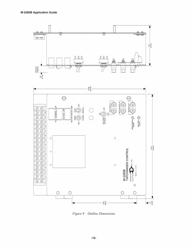
Figure 9 Outline Dimensions
12
34
56
78
910
1112
1314
15
TAPC
HAN
GER
CO
NTR
OL
MRE
EL
CT
CB
EK
W
nd
ai
e.
UA.
S.C
ICITH
CO
IN.
.
M-2
280B
AUTO
VOLT
AGE
1 AM
P
MAN
UAL
TEST
TER
MIN
AL 3
AM
P
MO
TOR
PO
WER
6 A
MP
OFF
LOW
ER
SOU
RC
EVO
LTAG
E
EXT
INT
RAI
SE
OFF
OFF
VOLT
AGE
IN
MO
TOR
PW
R IN
MET
ER O
UT
DR
AG H
AND
SR
ESET
LIG
HT
NEU
TRAL
8.00
[20.
3]
1.11
[2.8
2]12
.91
[32.
94]
13.8
8[3
5.26
]
4.91
[12.
47]
0.8
[2.0
3]
Max
imum
Proj
ectio
n

‑13‑
M-2280B Application Guide
Figure 10 M‑2280B Hole Drill Dimensions
CL8
[20.3]
3-7/8[9.8]
11[27.9]
Ø 0.29 X 4
1/4 - 20 X 1/2 [0.6 - 50.8 X 1.3] Stud - 4 Places
Inches [Centimeters]

-14-
M-2280B Application Guide
4.0 M-2001 Tapchanger ControlSoftware Settings
Adjust the BANDCENTER setting to the nominalvoltage desired. Adjust the BANDWIDTH settingto the desired voltage band, centered on theBandcenter setpoint, that the voltage must exceedbefore timer and subsequent tapchanger operationoccurs. Adjust the TIME DELAY setpoint to asufficient amount to eliminate excessive tapchangeroperations. The LINE DROP COMPENSATORshould be set for the line impedance from thetransformer to the load center. For furtherinformation, obtain Beckwith Electric ApplicationNote #17, “Basic Considerations for the Applicationof LTC Transformers and Associated Controls.”
4.1 M-0329B LTC BackupControl Settings
The BANDCENTER and BANDWIDTH dials on theM-0329B LTC Backup Control should be set so thatthe Block Lower limit is a small amount(approximately 2 V) below the lower band limit ofthe Tapchanger Control, and the Block Raise limitis a similar amount above the upper limit if linedrop compensation is not used.
If line drop compensation is used, the M-0329BBlock Raise limit should be set at the maximumvoltage desired at the transformer secondary underfull load.
The M-0329B LTC Backup Control also includes adeadband or runback function that regulates themaximum voltage from the transformer. This“Lower” function operates slightly above the BlockRaise limit and is connected to force the tapchangerto lower the voltage if the upper limit is exceeded.
-15-
M-2280B Application Guide
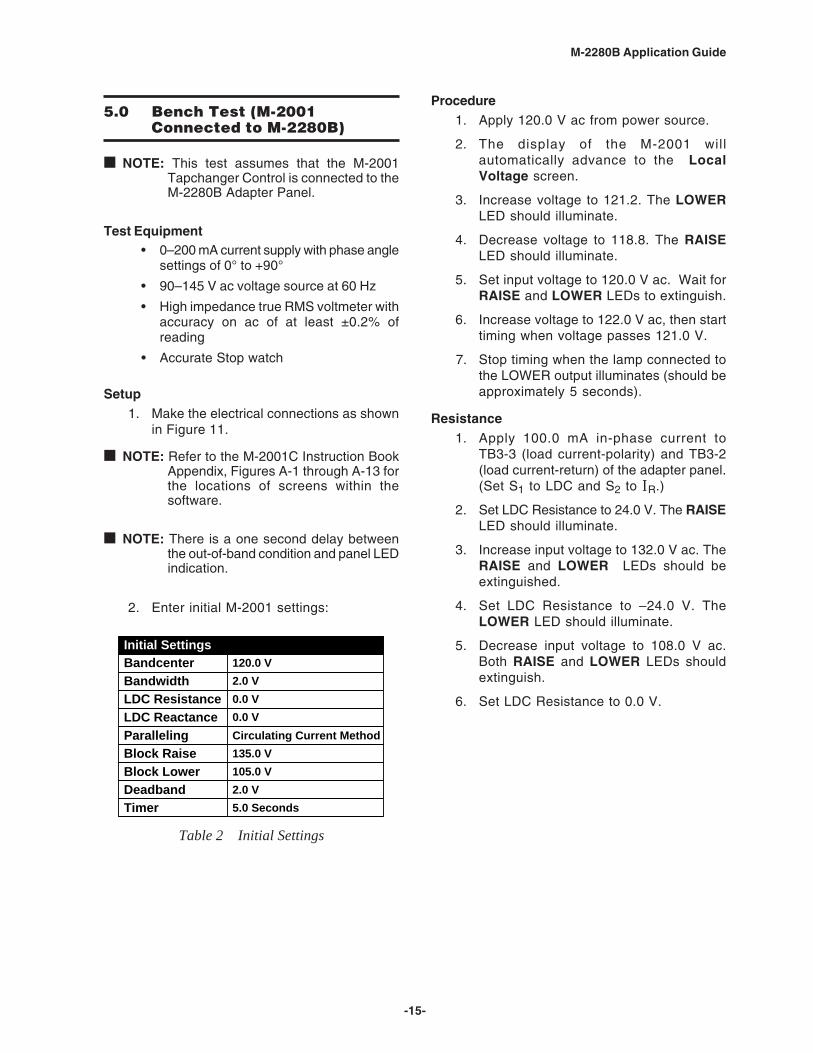
5.0 Bench Test (M-2001Connected to M-2280B)
■ NOTE: This test assumes that the M-2001Tapchanger Control is connected to theM-2280B Adapter Panel.
Test Equipment• 0–200 mA current supply with phase angle
settings of 0° to +90°
• 90–145 V ac voltage source at 60 Hz
• High impedance true RMS voltmeter withaccuracy on ac of at least ±0.2% ofreading
• Accurate Stop watch
Setup1. Make the electrical connections as shown
in Figure 11.
■ NOTE: Refer to the M-2001C Instruction BookAppendix, Figures A-1 through A-13 forthe locations of screens within thesoftware.
■ NOTE: There is a one second delay betweenthe out-of-band condition and panel LEDindication.
2. Enter initial M-2001 settings:
Initial SettingsBandcenterBandwidthLDC ResistanceLDC ReactanceParallelingBlock RaiseBlock LowerDeadbandTimer
Circulating Current Method
120.0 V2.0 V0.0 V0.0 V
5.0 Seconds
135.0 V105.0 V2.0 V
Table 2 Initial Settings
Procedure1. Apply 120.0 V ac from power source.
2. The display of the M-2001 willautomatically advance to the LocalVoltage screen.
3. Increase voltage to 121.2. The LOWERLED should illuminate.
4. Decrease voltage to 118.8. The RAISELED should illuminate.
5. Set input voltage to 120.0 V ac. Wait forRAISE and LOWER LEDs to extinguish.
6. Increase voltage to 122.0 V ac, then starttiming when voltage passes 121.0 V.
7. Stop timing when the lamp connected tothe LOWER output illuminates (should beapproximately 5 seconds).
Resistance1. Apply 100.0 mA in-phase current to
TB3-3 (load current-polarity) and TB3-2(load current-return) of the adapter panel.(Set S1 to LDC and S2 to IIIIIR.)
2. Set LDC Resistance to 24.0 V. The RAISELED should illuminate.
3. Increase input voltage to 132.0 V ac. TheRAISE and LOWER LEDs should beextinguished.
4. Set LDC Resistance to –24.0 V. TheLOWER LED should illuminate.
5. Decrease input voltage to 108.0 V ac.Both RAISE and LOWER LEDs shouldextinguish.
6. Set LDC Resistance to 0.0 V.
-16-
M-2280B Application Guide
Figure 11 M-2280B Test Procedure External Connection
� � � � � � � � �� �� �� �� �� �� �� � ���
���
���
����
��
� � ��
������������ ���������
������������������������
�����������
���������������������
�� � �� ��
��+��6�
��
�� ��8��9�
������!�����������!��������������������
������������"�����!�#���������������!����������
$%�&�����������������!�������������������������
��!���������������'�(������(�������)�����������
�������������������������������������*�����
����������!�����������������������������������������'
!"�#$
�
��� �+ �&
��3�"�::���4;���*�1+5
<���"0�� ����!
:�� ����6
�� ����:+.��3�)�.�9� �)�:�
*�� �3��1�+ ����" :�=��)�:�
���+��� ��3������ �4� ���5
���+��� ��3������ �4$����� �5
��:+.��3������!� :�
��:+.��3�����
��!� :�
*�� �3��1�+ ����" :�=��)�:�
<� ���
�� ���$��
�
�3��� 1�*�� �3
<� ������3.
8��3�>��1��
!:�� �������� ��)�:�
���1������ �4$����� �5
���1������ �4� ���5
% !% !
����&�'()*
+����,
-*.�/��0
� ���������&���
+����,
%
"''
�1
23�
�
+�
+�
��������+���������� ����������
4�::
���2����
��?/��-�&����3��
�5
4�::
���2��2��@A/����
�*��+�������A���
5
���
��
4����
4
(���!"�#
4 3 4 �
<��
<�, <�
<�
<�
<�
<,
<�
<�
�- �� �� - � �, , �� � � �� ���
���

-17-
M-2280B Application Guide
Reactance1. Apply 100.0 mA 90° leading current to
TB3-3 (load current-polarity) and TB3-2(load current-return) of the adapter panel.
2. Set S1 to LDC and S2 to IIIIIL.
3. Set LDC Reactance to 24.0 V. The LOWERLED should illuminate.
4. Decrease input voltage to 108.0 V ac.The RAISE and LOWER LEDs shouldbe extinguished.
5. Set LDC Reactance to –24.0 V. TheRAISE LED should illuminate.
6. Increase input voltage to 132.0 V ac.Both RAISE and LOWER LEDs shouldbe extinguished.
7. Set LDC Reactance to 0.0 V.
Paralleling1. Apply 100.0 mA 90° leading current to
TB3-9 (circulating current-polarity) andTB3-8 (circulating current-return) of theadapter panel.
2. The LOWER LED should illuminate.
3. Decrease voltage to 108.0 V ac. BothRAISE and LOWER LEDs should beextinguished.
4. Turn off current.
Voltage Source Switch1. Set AUTO/OFF/MANUAL switch to OFF.
2. Set VOLTAGE SOURCE switch to EXT.
3. Verify that there is no manual Raise orLower output.
4. Attach a voltmeter to Meter Out terminals.
5. Verify that no voltage is present.
6. Apply 120 V ac to both the Voltage Inand Motor Pwr In binding posts(Black-Neutral, Red-Hot).
7. Set the AUTO/OFF/MANUAL switch toAUTO.
8. Verify normal raise and lower operation.
9. Return the VOLTAGE SOURCE switchto INT.
Drag Hands Reset1. Verify that the DRAG HAND RESET switch
works by connecting a lamp or ac relayfrom TB3-13 (drag hands reset) to TB3-5(neutral) of the adapter panel. When theswitch is pressed, the connected indicatorshould function.
Counter/Neutral Light/Tap Position1. Set the M-2001 Tapchanger Control to
display the Operations Count screen.
2. Verify the counter operation by connectinga switch between TB3-12 (operationscounter input) and TB3-5 (neutral) of theadapter panel.
3. Lower the input voltage until the RAISELED lights. Allow the delay timer to timeout and then activate the switch betweenTB3-12 (operations counter input) andTB3-5 (neutral).
4. The tap position should change.
5. Jumper TB3-14 (neutral light) to TB3-5(neutral).
6. Set the neutral light switch S1, locatedon the adapter panel printed-circuit board,to the toggle down position.
7. The neutral light on the adapter panelshould light and the tap position shouldreturn to “0 Neutral.”
8. Remove the jumper.
Block Raise/Block Lower/Dead Band1. Set Block Raise to 126.0 V.
2. Set Block Lower to 114.0 V.
3. Set the M-2001 Tapchanger Control todisplay the Bias Voltage screen.
4. Press Enter.
5. Increase voltage to 126.5 V; BR shouldappear on the screen.
6. Increase voltage to 128.5 V; BR goesoff and FL appears on the screen.
7. Decrease voltage to 113.5 V; BL appearson the screen.
—Bench Test Complete—

-18-
M-2280B Application Guide
5.1 M-2001 Checkout Procedure
■ NOTE: This test of the M-2001 assumes thatthe unit remains connected to theM-2280B adapter panel.
Basic Operational Test1. Apply 120.0 V ac to TB3-4 (motor power)
and TB3-1 (regulated voltage) of theadapter panel.
2. Connect neutral to TB3-5 (neutral).
3. Verify local voltage y input voltage ±0.3V.
4. Apply 100.0 mA in-phase current toTB3-3 (load current-polarity) and TB3-2(load current-return) of the adapter panel.Verify Control Load IIIII y 100 mA andPower Factor y 1.0 ±0.02.
5. Apply 100.0 mA 90° leading current toTB3-9 (circulating current-polarity) andTB3-8 (circulating current-return) of theadapter panel.
6. Verify Control Circ IIIII y 100.0 mA ±2 mA.
7. Verify Up, Down and Enter buttons work.
—Checkout Procedure Complete—
5.2 In-Service Test
1. Set the M-2001 Tapchanger Control todisplay the Bias Voltage screen.
2. Press Enter.
3. Use Up and Down buttons to causeRAISE and LOWER outputs.
—In-Service Test Complete—
RETURN UNIT TO DESIRED SETTINGS
5.3 M-2280B CheckoutProcedure
■ NOTE: All Beckwith Electric units are fullycalibrated at the factory. There is noneed to recalibrate the units before initialinstallation.
Set the AUTO/OFF/MANUAL SWITCH to OFF.Inspect the MOTOR POWER and VOLTAGE fusesto ensure they are correctly sized and have notblown.
POWER1. Remove any external connection between
TB3-4 and TB3-1 which are located onthe adapter panel printed circuit board.Also remove any voltage applied to TB3-4externally. Using a voltmeter, make surethat the voltage applied to TB3-1 isnominal 120 V ac with respect to TB3-5(neutral). Apply power to TB3-1 (hot) andTB3-5 (neutral).
2. Connect a voltmeter to the METER OUTtest terminal on the front of the adapterpanel. 120 V ac should be indicated.
88888 WARNING: Voltage applied at the METEROUT test terminal may energize the regulatoror transformer to a high voltage through thevoltage transformer. Death or severe electricalshock can occur. Do not connect any voltagesource at the METER OUT test terminal.
▲ CAUTION: Do not reverse the ground and hotwires when connecting an external source. A 3 AGfuse (F2) is installed to protect the relay from damageif these connections are accidentally reversed. Sparefuses are supplied inside the fuse holders.
Units returned with only a blown fuse are not coveredby warranty, and a nominal repair charge will bemade for replacement of the fuse. Please check thefuse before returning the unit for repair, in order toavoid unnecessary repair charges.
3. Apply motor power to TB3-4 (hot) andTB3-5 (neutral). Set the AUTO/OFF/MANUAL switch to MANUAL and usingthe RAISE/OFF/LOWER switch, verify thatthe motor runs in the proper directionwhen this switch is in the RAISE andLOWER positions.

-19-
M-2280B Application Guide
4. Set the AUTO/OFF/MANUAL SWITCH tothe AUTO position. Refer to the FieldCheckout Procedure as found in the M-2001Status & Setpoint Review Guide of theM-2001 Tapchanger Control InstructionBook for test/operation procedures.
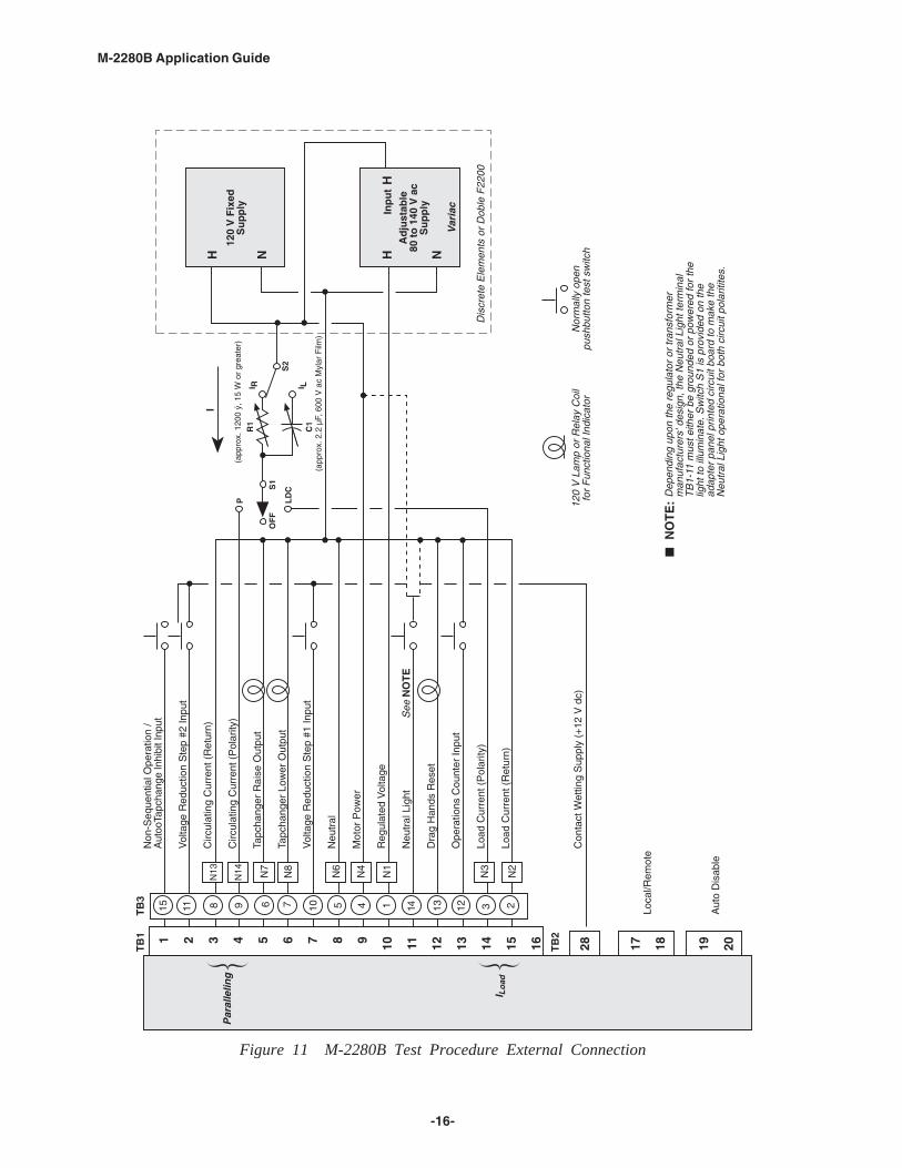
5. As shown in Figure 12 temporarily place ashorting device across the LDC-CTsecondary to short the line dropcompensator circuit, and place anothershorting device across TB3-8 and TB3-9to short the circulating current parallelinginput, for the load current check. Insert anammeter between the polarity input andTB3-3. Open the load current shortingdevice and with a known load on thetransformer or regulator, measure thecurrent in the load current circuit to ensurethat this current is correct for 0.2 A full load.
6. Replace the shorting device across theload current input and remove theammeter. Reconnect polarity to the unitand remove both jumpers. The LINE DROPCOMPENSATOR will be activated. CorrectCT polarity can be checked by simplyincorporating sufficient +R compensation.The regulator should time out and run soas to raise the output voltage.
88888 WARNING: In no case should the loadcurrent circuit be interrupted with the regulatoror transformer energized. Do not removeauxiliary current transformers without shortingthe current inputs. Death or severe electricalshock can occur.
VOLTAGE SOURCE SWITCHThe VOLTAGE SOURCE switch will disconnectall power from the unit when in the EXT positionwith no source connected to the front panel voltageand motor power inputs.
▲ CAUTION: Do not reverse the ground and hotwires when connecting an external source. A 3 AG(F2) is installed to protect the relay from damage ifthese connections are accidentally reversed.
With the VOLTAGE SOURCE switch in the EXTposition, the sensing and motor power circuits areconnected to the VOLTAGE IN and MOTOR PWRIN binding posts on the front panel. The unit canbe tested using an external 120 V rms source ofproper polarity applied to these terminals. Testingcan be accomplished by adjusting the amplitudeof the external source.
���� ���-2 %-!5#3 "!�3"�
��,���� �:��B�����:���
,
� �"-1� 633#!�-67 �
-
��-
����8-
�
�1 � �7777$��-
+����(�*9(�
!��8���,��� �����7
� � ����2������(�6�(�
+����(�*9(�
Figure 12 Setup for Current Checkout Procedure

-20-
M-2280B Application Guide
This Page Left Intentionally Blank
Legal Information
PatentThe units described in this manual are covered byU.S. Patents, with other patents pending.
Buyer shall hold harmless and indemnify the Seller,its directors, officers, agents, and employees fromany and all costs and expense, damage or loss,resulting from any alleged infringementof UnitedStates Letters Patent or rights accruing thereform ortrademarks, whether federal, state, or common law,arising from the Seller’s compliance with Buyer’sdesigns, specifications, or instructions.
WarrantySeller hereby warrants that the goods which are thesubject matter of this contract will be manufacturedin a good workmanlike manner and all materialsused herein will be new and reasonably suitable forthe equipment. Seller warrants that if, during aperiod of five years from date of shipment of theequipment, the equipment rendered shall be foundby the Buyer to be faulty or shall fail to peform inaccordance with Seller’s specifications of theproduct, Seller shall at his expense correct thesame, provided, however, that Buyers shall ship theequipment prepaid to Seller’s facility. The Seller’sresponsibility hereunder shall be limited to replace-ment value of the equipment furnished under thiscontract.
Seller makes no warranties expressed or impliedother than those set out above. Seller specificallyexcludes the implied warranties of merchantibilityand fitness for a particular purpose. There are nowarranties which extend beyond the descriptioncontained herein. In no event shall Seller be liable forconsequential, exemplary, or punitive damages ofwhatever nature.
Any equipment returned for repair must be sentwith transportation charges prepaid. The equipmentmust remain the property of the Buyer. The afore-mentioned warranties are void if the value of theunit is invoiced to the Seller at the time of return.
IndemnificationThe Seller shall not be liable for any propertydamages whatsoever or for any loss or damagearising out of, connected with, or resulting fromthis contract, or from the performance or breachthereof, or from all services covered by or furnishedunder this contract.
In no event shall the Seller be liable for special,incidental, exemplary, or consequential damages,including but not limited to, loss of profits orrevenue, loss of use of the equipment or anyassociated equipment, cost of capital, cost ofpurchased power, cost of substitute equipment,facilities or services, downtime costs, or claims ordamages of customers or employees of the Buyerfor such damages, regardless of whether said claimor damages is based on contract, warranty, tortincluding negligence, or otherwise.
Under no circumstances shall the Seller be liablefor any personal injury whatsoever.
It is agreed that when the equipment furnishedhereunder are to be used or performed in connec-tion with any nuclear installation, facility, oractivity, Seller shall have no liability for anynuclear damage, personal injury, property damage,or nuclear contamination to any property located ator near the site of the nuclear facility. Buyer agreesto indemnify and hold harmless the Seller againstany and all liability associated therewith whatso-ever whether based on contract, tort, or otherwise.Nuclear installation or facility means any nuclearreactor and includes the site on which any of theforegoing is located, all operations conducted onsuch site, and all premises used for such opera-tions.
Notice:Any illustrations and descriptions by BeckwithElectric Co., Inc. are for the sole purpose ofidentification.
The drawings and/or specifications enclosed hereinare the proprietary property of Beckwith ElectricCo., Inc., and are issued in strict confidence;therefore, shall not be used as a basis of reproduc-tion of the apparatus described therein withoutwritten permission of Beckwith Electric Co., Inc.
No illustration or description contained hereinshall be construed as an express warranty ofaffirmation, promise, description, or sample, andany and all such express warranties are specificallyexcluded nor shall such illustration or descriptionimply a warranty that the product is merchantableor fit for a particular purpose. There shall be nowarranties which extend beyond those contained inthe Beckwith Electric Co., Inc. terms of sale.
All rights reserved by Beckwith Electric Co., Inc. No reproduction may be made without prior written approvalof the Company.

This Page Left Intentionally Blank

© 1998 Beckwith Electric Co.Printed in USA
800‑2280B‑AG‑04MC2 04/15
BECKWITH ELECTRIC CO., INC.6190 ‑ 118th Avenue North • Largo, Florida 33773‑3724 U.S.A.
PHONE (727) 544‑2326 • FAX (727) 546‑[email protected]
www.beckwithelectric.comISO 9001:2008


