Lake Shore Cryotronics, Inc. Model MH-2.5 Helmholtz Coil Application Guide Page 1 Application Note Helmholtz Coil Model MH-2.5 Magnetic Field Standard Lake Shore Cryotronics, Inc. 575 McCorkle Blvd. Westerville, Ohio 43082-8888 USA [email protected][email protected]www.lakeshore.com Fax: (614) 891-1392 Telephone: (614) 891-2243 Methods and apparatus disclosed and described herein have been developed solely on company funds of Lake Shore Cryotronics, Inc. No government or other contractual support or relationship whatsoever has existed which in any way affects or mitigates proprietary rights of Lake Shore Cryotronics, Inc. in these developments. Methods and apparatus disclosed herein may be subject to U.S. Patents existing or applied for. Lake Shore Cryotronics, Inc. reserves the right to add, improve, modify, or withdraw functions, design modifications, or products at any time without notice. Lake Shore shall not be liable for errors contained herein or for incidental or consequential damages in connection with furnishing, performance, or use of this material.
Transcript
Lake Shore Cryotronics, Inc.
Model MH-2.5 Helmholtz Coil Application Guide Page 1
Application Note
Helmholtz Coil
Model MH-2.5
Magnetic Field Standard
Lake Shore Cryotronics, Inc. 575 McCorkle Blvd. Westerville, Ohio 43082-8888 USA
Methods and apparatus disclosed and described herein have been developed solely on company funds of Lake Shore Cryotronics, Inc. No government or other contractual support or relationship whatsoever has existed which in any way affects or mitigates proprietary rights of Lake Shore Cryotronics, Inc. in these
developments. Methods and apparatus disclosed herein may be subject to U.S. Patents existing or applied for. Lake Shore Cryotronics, Inc. reserves the right
to add, improve, modify, or withdraw functions, design modifications, or products at any time without notice. Lake Shore shall not be liable for errors contained herein or for incidental or consequential damages in connection with furnishing, performance, or use of this material.
Page 2 Model MH-2.5 Helmholtz Coil Application Guide
Lake Shore Limited Warranty
WARRANTY PERIOD: THREE (3) YEARS
1. Lake Shore warrants that products manufactured by Lake Shore (the “Product”) will be free from defects in materials and workmanship for
three years from the date of Purchaser’s physical receipt of the Product (the “Warranty Period”). If Lake Shore receives notice of any such
defects during the Warranty Period and the defective Product is shipped freight prepaid back to Lake Shore, Lake Shore will, at its option,
either repair or replace the Product (if it is so defective) without charge for parts, service labor or associated customary return shipping cost to
the Purchaser. Replacement for the Product may be by either new or equivalent in performance to new. Replacement or repaired parts, or a
replaced Product, will be warranted for only the unexpired portion of the original warranty or 90 days (whichever is greater).
2. Lake Shore warrants the Product only if the Product has been sold by an authorized Lake Shore employee, sales representative, dealer or an
authorized Lake Shore original equipment manufacturer (OEM).
3. The Product may contain remanufactured parts equivalent to new in performance or may have been subject to incidental use when it is
originally sold to the Purchaser.
4. The Warranty Period begins on the date of Purchaser’s physical receipt of the Product or later on the date of operational training and
verification (OT&V) of the Product if the service is performed by Lake Shore, provided that if the Purchaser schedules or delays the Lake
Shore OT&V for more than 30 days after delivery then the Warranty Period begins on the 31st day after Purchaser’s physical receipt of the
Product.
5. This limited warranty does not apply to defects in the Product resulting from (a) improper or inadequate installation (unless OT&V services
are performed by Lake Shore), maintenance, repair or calibration, (b) fuses, software, power surges, lightning and non-rechargeable batteries,
(c) software, interfacing, parts or other supplies not furnished by Lake Shore, (d) unauthorized modification or misuse, (e) operation outside of
the published specifications, (f) improper site preparation or site maintenance (g) natural disasters such as flood, fire, wind, or earthquake, or
(h) damage during shipment other than original shipment to you if shipped through a Lake Shore carrier.
6. This limited warranty does not cover: (a) regularly scheduled or ordinary and expected recalibrations of the Product; (b) accessories to the
Product (such as probe tips and cables, holders, wire, grease, varnish, feedthroughs, etc.); (c) consumables used in conjunction with the
Product (such as probe tips and cables, probe holders, sample tails, rods and holders, ceramic putty for mounting samples, Hall sample cards,
Hall sample enclosures, etc.); or, (d) non-Lake Shore branded Products that are integrated with the Product.
7. To the extent allowed by applicable law,, this limited warranty is the only warranty applicable to the Product and replaces all other warranties
or conditions, express or implied, including, but not limited to, the implied warranties or conditions of merchantability and fitness for a
particular purpose. Specifically, except as provided herein, Lake Shore undertakes no responsibility that the products will be fit for any
particular purpose for which you may be buying the Products. Any implied warranty is limited in duration to the warranty period. No oral or
written information, or advice given by the Company, its Agents or Employees, shall create a warranty or in any way increase the scope of
this limited warranty. Some countries, states or provinces do not allow limitations on an implied warranty, so the above limitation or exclusion
might not apply to you. This warranty gives you specific legal rights and you might also have other rights that vary from country to country,
state to state or province to province.
8. Further, with regard to the United Nations Convention for International Sale of Goods (CISC,) if CISG is found to apply in relation to this
agreement, which is specifically disclaimed by Lake Shore, then this limited warranty excludes warranties that: (a) the Product is fit for the
purpose for which goods of the same description would ordinarily be used, (b) the Product is fit for any particular purpose expressly or
impliedly made known to Lake Shore at the time of the conclusion of the contract. (c) the Product is contained or packaged in a manner usual
for such goods or in a manner adequate to preserve and protect such goods where it is shipped by someone other than a carrier hired by Lake
Shore.
9. Lake Shore disclaims any warranties of technological value or of non-infringement with respect to the Product and Lake Shore shall have no
duty to defend, indemnify, or hold harmless you from and against any or all damages or costs incurred by you arising from the infringement of
patents or trademarks or violation or copyrights by the Product.
10. This warranty is not transferrable.
11. Except to the extent prohibited by applicable law, neither Lake Shore nor any of its subsidiaries, affiliates or suppliers will be held liable for
direct, special, incidental, consequential or other damages (including lost profit, lost data, or downtime costs) arising out of the use, inability
to use or result of use of the product, whether based in warranty, contract, tort or other legal theory, regardless whether or not Lake Shore has
been advised of the possibility of such damages. Purchaser’s use of the Product is entirely at Purchaser’s risk. Some countries, states and
provinces do not allow the exclusion of liability for incidental or consequential damages, so the above limitation may not apply to you.
12. This limited warranty gives you specific legal rights, and you may also have other rights that vary within or between jurisdictions where the
product is purchased and/or used. Some jurisdictions do not allow limitation in certain warranties, and so the above limitations or exclusions
of some warranties stated above may not apply to you.
13. Except to the extent allowed by applicable law, the terms of this limited warranty statement do not exclude, restrict or modify the mandatory
statutory rights applicable to the sale of the product to you.
Lake Shore Cryotronics, Inc.
Model MH-2.5 Helmholtz Coil Application Guide Page 3
CERTIFICATION Lake Shore certifies that this product has been inspected and tested in accordance with its published specifications and that this product met
its published specifications at the time of shipment. The accuracy and calibration of this product at the time of shipment are traceable to the
United States National Institute of Standards and Technology (NIST); formerly known as the National Bureau of Standards (NBS).
transmitted, in any form or by any means, electronic, mechanical, photocopying, recording, or otherwise, without the express written
permission of Lake Shore.
Lake Shore Cryotronics, Inc.
Page 4 Model MH-2.5 Helmholtz Coil Application Guide
1.0 GENERAL
The Lake Shore Model MH-2.5 Helmholtz coil provides an economical method of producing small volume, relatively
low-value magnetic fields. The field produced is approximately 30 G/A. A calibration constant is provided which allows the
user to generate accurate field values with a known current input. The field homogeneity is specified to exist in a volume
centered in the coil interior.
2.0 SPECIFICATIONS
2.1 PHYSICAL SPECIFICATIONS
4.2"
5.0"
4.0"
3.0"
2.5" BORE
BANANA JACKS
(CURRENT INPUT)
1.25" WIDE
1.00" HIGH
OPENING
THRU
BOTH SIDES.
+B
Figure 1. MH-2.5 Physical Dimensions
Table 1. MH-2.5 Electrical and Magnetic Specifications
Parameter Model MH-2.5
Description Helmholtz coil, 2.5 in inside diameter, 0.5% center field accuracy
Field strength 30 G at 1 A (approximate—an exact value is supplied)
Maximum continuous current 2 A DC (or RMS)
Field uniformity 0.5% of center value, within a cylindrical volume 0.75 in long,
0.75 in diameter, centered in the coil interior
DC coil resistance/inductance 3 Ω/6.3 mH
Operating ambient temperature range –20 °C to +40 °C
Lake Shore Cryotronics, Inc.
Model MH-2.5 Helmholtz Coil Application Guide Page 5
3.0 INSTALLATION
3.1 GENERAL
Utilization of a Helmholtz coil is relatively straightforward. A current is supplied to the coil, the current magnitude is
measured, and the magnetic field value is calculated. A DC or AC current can be used. However, please read the
paragraph on AC Operation to be aware of limitations and possible safety hazards when using AC currents.
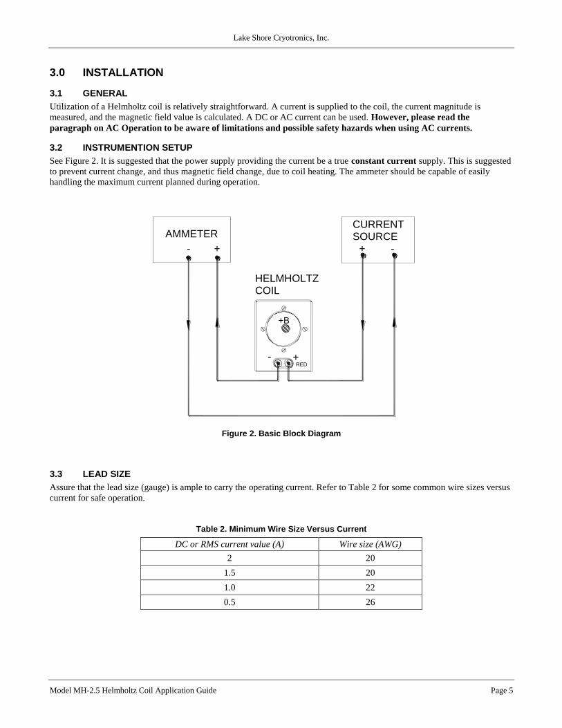
3.2 INSTRUMENTION SETUP
See Figure 2. It is suggested that the power supply providing the current be a true constant current supply. This is suggested
to prevent current change, and thus magnetic field change, due to coil heating. The ammeter should be capable of easily
handling the maximum current planned during operation.
+B
RED
COILHELMHOLTZ
-
AMMETER
- +
+
SOURCECURRENT
+ -
Figure 2. Basic Block Diagram
3.3 LEAD SIZE
Assure that the lead size (gauge) is ample to carry the operating current. Refer to Table 2 for some common wire sizes versus
current for safe operation.
Table 2. Minimum Wire Size Versus Current
DC or RMS current value (A) Wire size (AWG)
2 20
1.5 20
1.0 22
0.5 26
Lake Shore Cryotronics, Inc.
Page 6 Model MH-2.5 Helmholtz Coil Application Guide
3.4 POLARITY
The hook-up polarities shown in Figure 2 provide a field vector direction as shown (also see Figure 1) when a positive
current is measured on the ammeter. When the current direction is reversed, the field direction will likewise change by 180.
3.5 MOUNTING CONSIDERATIONS
Place the MH-2.5 on a solid, non-magnetic surface such as a wood or plastic table. The presence of nearby ferrous metal will
harm the accuracy of the field constant. Shielding must be used very cautiously, and its effect proven to be negligible versus
the open field configuration.
If the position of the coil must be fixed, it is suggested that “stop-blocks” be used to prevent sliding on a surface. Drilling
holes in the end supports can be done, but is discouraged due to the high probability of coil damage.
4.0 OPERATION
4.1 GENERAL
A Helmholtz coil makes a very convenient low field standard. The magnetic field produced per current input can be
accurately calibrated using a Hall-effect gaussmeter. The magnetic field waveform matches that of the current. Thus,
complex AC as well as DC fields can be generated.
4.2 DETERMINING THE MAGNETIC FIELD VALUE
The coil has a label indicating its magnetic field flux density per current. This constant is given as "G/A".
Therefore, all the user has to do is multiply the known current in A times the above constant. For example, if the constant is
29.97 G/A and the current is measured at 0.39 A, then the field value (in the center of the coil) is:
0.39 × 29.97 = 11.69 G.
If the current is DC, the field is DC.
If the current is ACrms, the field is ACrms.
The field waveform matches that of the current.
If the user wants to work in SI units, the G value can be converted to T by multiplying by 10-4.
(11.69 G) × (10-4) = 1.169 mT
4.3 FLUX DENSITY (B) VERSUS MAGNETIC FIELD STRENGTH (H)
The flux density and magnetic field strength in air are related approximately by the permeability of vacuum, 0. At least in
air, the generated magnetic field can be converted to units field strength.
B = 0 H H = B / 0
In the cgs system, calculations are somewhat simple due to the fact that 0 is given the value 1.0. Therefore, in our example
in paragraph 4.2, the magnetic field strength is 11.69 G divided by 1 to give 11.69 Oe (the unit of H in the cgs system).
Conversions in the SI system are slightly more difficult because 0 is 4 × 10⁻⁷. Again, going back to our example in 4.2,
we calculate magnetic field strength as 1.169 × 10⁻³ divided by 4 × 10⁻⁷ to give 930 A/m (the unit of H in the SI system).
Lake Shore Cryotronics, Inc.
Model MH-2.5 Helmholtz Coil Application Guide Page 7
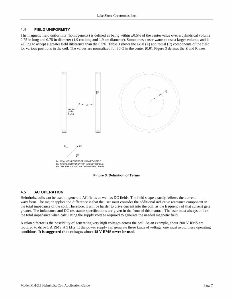
4.4 FIELD UNIFORMITY
The magnetic field uniformity (homogeneity) is defined as being within 0.5% of the center value over a cylindrical volume
0.75 in long and 0.75 in diameter (1.9 cm long and 1.9 cm diameter). Sometimes a user wants to use a larger volume, and is
willing to accept a greater field difference than the 0.5%. Table 3 shows the axial (Z) and radial (R) components of the field
for various positions in the coil. The values are normalized for 30 G in the center (0,0). Figure 3 defines the Z and R axes.
R
Br
Z
Bz
Br
Bz
Bm
Br, RADIAL COMPONENT OF MAGNETIC FIELD.
Bz, AXIAL COMPONENT OF MAGNETIC FIELD
Bm, VECTOR MAGNITUDE OF MAGNETIC FIELD.
OriginZ=0.0R=0.0
Figure 3. Definition of Terms
4.5 AC OPERATION
Helmholtz coils can be used to generate AC fields as well as DC fields. The field shape exactly follows the current
waveform. The major application difference is that the user must consider the additional inductive reactance component in
the total impedance of the coil. Therefore, it will be harder to drive current into the coil, as the frequency of that current gets
greater. The inductance and DC resistance specifications are given in the front of this manual. The user must always utilize
the total impedance when calculating the supply voltage required to generate the needed magnetic field.
A related factor is the possibility of generating very high voltages across the coil. As an example, about 200 V RMS are
required to drive 1 A RMS at 5 kHz. If the power supply can generate these kinds of voltage, one must avoid these operating
conditions. It is suggested that voltages above 48 V RMS never be used.
Lake Shore Cryotronics, Inc.
Page 8 Model MH-2.5 Helmholtz Coil Application Guide
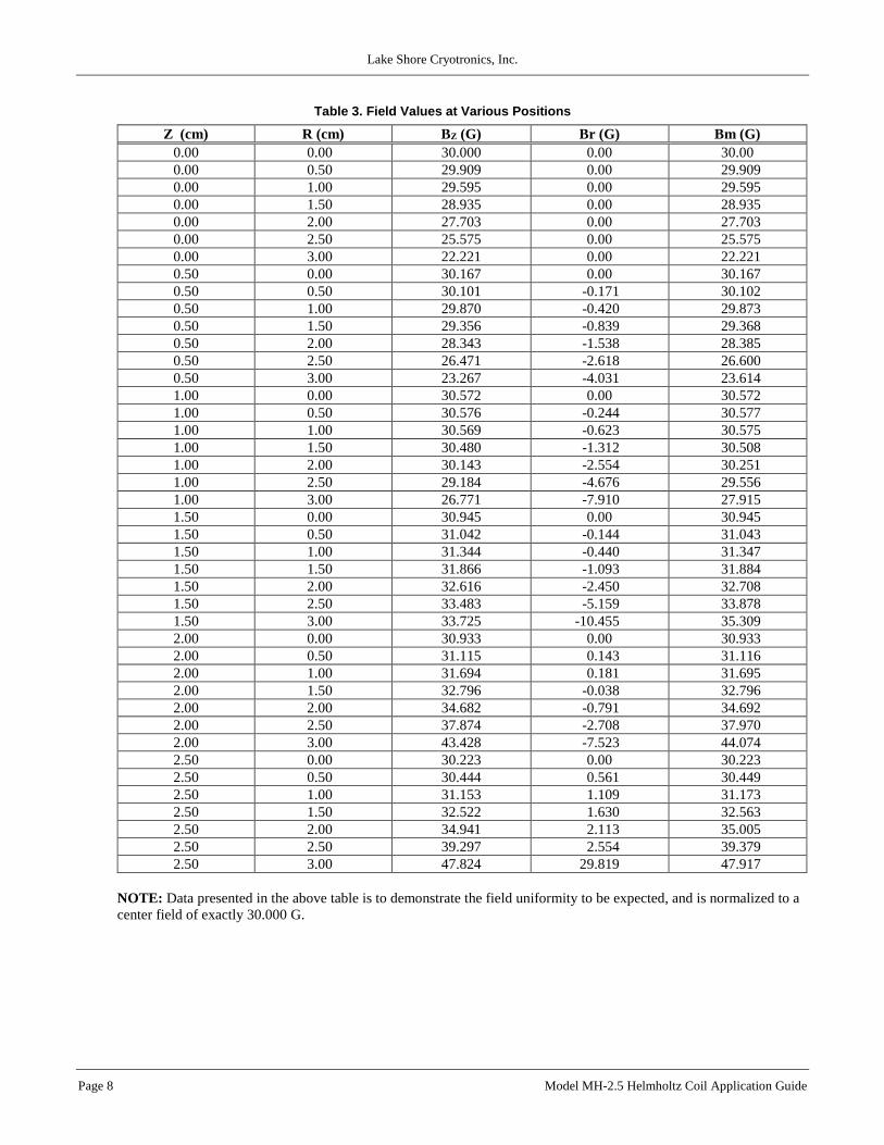
Table 3. Field Values at Various Positions
Z (cm) R (cm) BZ (G) Br (G) Bm (G)
0.00 0.00 30.000 0.00 30.00
0.00 0.50 29.909 0.00 29.909
0.00 1.00 29.595 0.00 29.595
0.00 1.50 28.935 0.00 28.935
0.00 2.00 27.703 0.00 27.703
0.00 2.50 25.575 0.00 25.575
0.00 3.00 22.221 0.00 22.221
0.50 0.00 30.167 0.00 30.167
0.50 0.50 30.101 -0.171 30.102
0.50 1.00 29.870 -0.420 29.873
0.50 1.50 29.356 -0.839 29.368
0.50 2.00 28.343 -1.538 28.385
0.50 2.50 26.471 -2.618 26.600
0.50 3.00 23.267 -4.031 23.614
1.00 0.00 30.572 0.00 30.572
1.00 0.50 30.576 -0.244 30.577
1.00 1.00 30.569 -0.623 30.575
1.00 1.50 30.480 -1.312 30.508
1.00 2.00 30.143 -2.554 30.251
1.00 2.50 29.184 -4.676 29.556
1.00 3.00 26.771 -7.910 27.915
1.50 0.00 30.945 0.00 30.945
1.50 0.50 31.042 -0.144 31.043
1.50 1.00 31.344 -0.440 31.347
1.50 1.50 31.866 -1.093 31.884
1.50 2.00 32.616 -2.450 32.708
1.50 2.50 33.483 -5.159 33.878
1.50 3.00 33.725 -10.455 35.309
2.00 0.00 30.933 0.00 30.933
2.00 0.50 31.115 0.143 31.116
2.00 1.00 31.694 0.181 31.695
2.00 1.50 32.796 -0.038 32.796
2.00 2.00 34.682 -0.791 34.692
2.00 2.50 37.874 -2.708 37.970
2.00 3.00 43.428 -7.523 44.074
2.50 0.00 30.223 0.00 30.223
2.50 0.50 30.444 0.561 30.449
2.50 1.00 31.153 1.109 31.173
2.50 1.50 32.522 1.630 32.563
2.50 2.00 34.941 2.113 35.005
2.50 2.50 39.297 2.554 39.379
2.50 3.00 47.824 29.819 47.917
NOTE: Data presented in the above table is to demonstrate the field uniformity to be expected, and is normalized to a
center field of exactly 30.000 G.
Lake Shore Cryotronics, Inc.
Model MH-2.5 Helmholtz Coil Application Guide Page 9
4.6 OPERATION AT HIGHER CURRENTS
The maximum, continuous operating current is specified as 2 A DC or AC RMS. Though non-destructive to the MH-2.5 coil
itself, the coil wire may become quite hot to the touch. All users are cautioned not to touch the actual coil wires during
high current operation.
Brief excursions (a few seconds long) to values of current two or three times the maximum continuous value are allowable.
This must be done cautiously, and the coil structure temperature monitored for overheating. Long cool down periods between
these higher current excursions are mandatory.
5.0 THEORY
Helmholtz coils are very useful when relatively accurate, low value magnetic fields are required. The coil is in reality a pair
of coils with very specific diameter and separation. The theory is that along the coil axis, the reduction in field as one moves
away from one coil is compensated for by the increase in field as one nears the other. The magnetic flux density (B) or field
strength (H) is directly proportional to the applied current in the coils. Thus, the field can be accurately defined as a function
of the current.
Due to its split configuration the Helmholtz coil allows entry from the side or from either end. The field is relatively uniform
in a cylindrical volume located on the axis, centered between the coils. A field homogeneity of ±0.5% is easily specified over
a volume whose diameter is about 25% of the coil diameter and length is 50% of the coil spacing.
W
COILRADIUS
R=W
INDIVIDUAL, CIRCULARCOILS OF "N" TURNSEACH.
B
CYLINDRICAL VOLUMEOF SPECIFIED UNIFORMITY.
Figure 4. Typical Helmholtz Coil
The field value for a standard Helmholtz coil can be calculated from the simple equation:
B = 0.8991 NI
R
where:
B is magnetic flux density in G,
N is number of turns in each one of the two coils,
I is the current in series connected coils, and
R is the coil radius in cm.
Lake Shore Cryotronics, Inc.
Page 10 Model MH-2.5 Helmholtz Coil Application Guide
6.0 GLOSSARY OF TERMINOLOGY accuracy. The degree of correctness with which a measured value agrees with the true value.2
ampere. The constant current that, if maintained in two straight parallel conductors of infinite length, of negligible circular cross section,
and placed one meter apart in a vacuum, would produce between these conductors a force equal to 2 × 10⁻⁷ newton per meter of length.2
This is one of the base units of the SI.
ampere-turn. A MKS unit of magnetomotive force equal to the magnetomotive force around a path linking one turn of a conducting loop
carrying a current of one ampere; or 1.26 gilberts.
ampere/meter (A/m). The SI unit for magnetic field strength (H). 1 ampere/meter = 4/1000 oersted 0.01257 oersted.
cgs system of units. A system in which the basic units are the centimeter, gram, and second.2
coercive force (coercive field). The magnetic field strength (H) required to reduce the magnetic induction (B) in a magnetic material to
zero.
coercivity. generally used to designate the magnetic field strength (H) required to reduce the magnetic induction (B) in a magnetic material
to zero from saturation. The coercivity would be the upper limit to the coercive force.
compliance voltage. See current source.
current source. A type of power supply that supplies a constant current through a variable load resistance by automatically varying its
compliance voltage. A single specification given as “compliance voltage” means the output current is within specification when the
compliance voltage is between zero and the specified voltage.
deviation. The difference between the actual value of a controlled variable and the desired value corresponding to the setpoint.1
differential permeability. The slope of a B versus H curve: µd = dB/dH.
differential susceptibility. The slope of a M versus H curve: d = dM/dH.
electromagnet. A device in which a magnetic field is generated as the result of electrical current passing through a helical conducting coil.
It can be configured as an iron-free solenoid in which the field is produced along the axis of the coil, or an iron-cored structure in which
the field is produced in an air gap between pole faces. The coil can be water cooled copper or aluminum, or superconductive.
electron. An elementary particle containing the smallest negative electric charge. Note: The mass of the electron is approximately equal to
1/1837 of the mass of the hydrogen atom.2
error. Any discrepancy between a computed, observed, or measured quantity and the true, specified, or theoretically correct value or
condition.2
flux (). The electric or magnetic lines of force in a region.1
gamma. A cgs unit of low-level flux density, where 100,000 gamma equals one gauss, or 1 gamma equals 10–5 gauss.
gauss (G). The cgs unit for magnetic flux density (B). 1 gauss = 10–4 tesla = 1 Mx/cm2 = line/cm2. Named for Karl Fredrich Gauss (1777 –
1855) a German mathematician, astronomer, and physicist.
gaussian system (units). A system in which centimeter-gram-second units are used for electric and magnetic qualities.
gilbert (Gb). A cgs electromagnetic unit of the magnetomotive force required to produce one maxwell of magnetic flux in a magnetic
circuit of unit reluctance. One gilbert is equal to 10/4 ampere-turn. Named for William Gilbert (1540 – 1603), an English physicist;
hypothesized that the earth is a magnet.
gilbert per centimeter. Practical cgs unit of magnet intensity. Gilberts per cm are the same as oersteds.
Greek alphabet. The Greek alphabet is defined as follows:
Alpha Iota Rho
Beta Kappa Sigma
Gamma Lambda Tau
Delta Mu Upsilon
Epsilon Nu Phi
Zeta Xi Chi
Eta Omicron Psi
Theta Pi Omega
Hall effect. The generation of an electric potential perpendicular to both an electric current flowing along a thin conducting material and an
external magnetic field applied at right angles to the current. Named for Edwin H. Hall (1855 – 1938), American physicist.
Helmholtz coils. A pair of flat, circular coils having equal numbers of turns and equal diameters, arranged with a common axis, and
connected in series; used to obtain a magnetic field more nearly uniform than that of a single coil.1
hysteresis. The dependence of the state of a system on its previous history, generally in the form of a lagging of a physical effect behind its
cause.1 Also see magnetic hysteresis.
initial permeability. The permeability determined at H = 0 and B = 0.
initial susceptibility. The susceptibility determined at H = 0 and M = 0.
Lake Shore Cryotronics, Inc.
Model MH-2.5 Helmholtz Coil Application Guide Page 11
international system of units (SI). A universal coherent system of units in which the following seven units are considered basic: meter,
kilogram, second, ampere, kelvin, mole, and candela. The International System of Units, or Système International d'Unités (SI), was
promulgated in 1960 by the Eleventh General Conference on Weights and Measures. For definition, spelling, and protocols, see
Reference 3 for a short, convenient guide.
intrinsic coercivity. The magnetic field strength (H) required to reduce the magnetization (M) or intrinsic induction in a magnetic material
to zero.
intrinsic induction. The contribution of the magnetic material (Bi) to the total magnetic induction (B).
Bi = B – µoH (SI) Bi = B – H (cgs)
line of flux. An imaginary line in a magnetic field of force whose tangent at any point gives the direction of the field at that point; the lines
are spaced so that the number through a unit area perpendicular to the field represents the intensity of the field. Also known as a
Maxwell in the cgs system of units.
magnetic air gap. The air space, or non-magnetic portion, of a magnetic circuit.
magnetic field strength (H). The magnetizing force generated by currents and magnetic poles. For most applications, the magnetic field
strength can be thought of as the applied field generated, for example, by a superconducting magnet. The magnetic field strength is not a
property of materials. Measure in SI units of A/m or cgs units of oersted.
magnetic flux density (B). Also referred to as magnetic induction. This is the net magnetic response of a medium to an applied field, H.
The relationship is given by the following equation: B = µo (H + M) for SI, and B = H + 4M for cgs, where H = magnetic field strength,
M = magnetization, and µo = permeability of free space = 4 × 10⁻⁷ H/m.
magnetic hysteresis. The property of a magnetic material where the magnetic induction (B) for a given magnetic field strength (H)
depends upon the past history of the samples magnetization.
magnetic induction (B). See magnetic flux density.
magnetic moment (m). This is the fundamental magnetic property measured with dc magnetic measurements systems such as a vibrating
sample magnetometer, extraction magnetometer, SQUID magnetometer, etc. The exact technical definition relates to the torque exerted
on a magnetized sample when placed in a magnetic field. Note that the moment is a total attribute of a sample and alone does not
necessarily supply sufficient information in understanding material properties. A small highly magnetic sample can have exactly the
same moment as a larger weakly magnetic sample (see Magnetization). Measured in SI units as A·m2 and in cgs units as emu. 1 emu =
10–3 A·m2.
magnetic scalar potential. The work which must be done against a magnetic field to bring a magnetic pole of unit strength from a
reference point (usually at infinity) to the point in question. Also known as magnetic potential.1
magnetic units. Units used in measuring magnetic quantities. Includes ampere-turn, gauss, gilbert, line of force, maxwell, oersted, and unit
magnetic pole.
magnetization (M). This is a material specific property defined as the magnetic moment (m) per unit volume (V). M = m/V. Measured in
SI units as A/m and in cgs units as emu/cm3. 1 emu/cm3 = 103 A/m. Since the mass of a sample is generally much easier to determine
than the volume, magnetization is often alternately expressed as a mass magnetization defined as the moment per unit mass.
magnetostatic. Pertaining to magnetic properties that do not depend upon the motion of magnetic fields.1
Maxwell (Mx). A cgs electromagnetic unit of magnetic flux, equal to the magnetic flux which produces an electromotive force of 1 abvolt
in a circuit of one turn link the flux, as the flux is reduced to zero in 1 second at a uniform rate.1
MKSA System of Units. A system in which the basic units are the meter, kilogram, and second, and the ampere is a derived unit defined
by assigning the magnitude 4 × 10⁻⁷ to the rationalized magnetic constant (sometimes called the permeability of space).
oersted (Oe). The cgs unit for the magnetic field strength (H). 1 oersted = (1000)/(4) ampere/meter 79.58 ampere/meter.
ohm (). The SI unit of resistance (and of impedance). The ohm is the resistance of a conductor such that a constant current of one ampere
in it produces a voltage of one volt between its ends.2
permeability. Material parameter which is the ratio of the magnetic induction (B) to the magnetic field strength (H): µ = B/H.
Also see Initial Permeability and Differential Permeability.
precision. Careful measurement under controlled conditions which can be repeated with similar results. See repeatability.
prefixes. SI prefixes used throughout this manual are as follows:
Factor Prefix Symbol 1024 yotta Y 1021 zetta Z
1018 exa E
1015 peta P 1012 tera T
109 giga G
106 mega M 103 kilo k
102 hecto h
101 deka da
Factor Prefix Symbol 10–1 deci d 10–2 centi c
10–3 milli m
10–6 micro µ 10–9 nano n
10–12 pico p
10–15 femto f 10–18 atto a
10–21 zepto z
10–24 yocto y
Lake Shore Cryotronics, Inc.
Page 12 Model MH-2.5 Helmholtz Coil Application Guide
remanence. The remaining magnetic induction in a magnetic material when the material is first saturated and then the applied field is
reduced to zero. The remanence would be the upper limit to values for the remanent induction. Note that no strict convention exists for
the use of remanent induction and remanence and in some contexts the two terms may be used interchangeably.
remanent induction. The remaining magnetic induction in a magnetic material after an applied field is reduced to zero.
Also see remanence.
repeatability. The closeness of agreement among repeated measurements of the same variable under the same conditions.2
See precision.
resolution. The degree to which nearly equal values of a quantity can be discriminated.2
measurement resolution. The ability of an instrument to resolve a measured quantity. For digital instrumentation this is often defined by
the analog-to-digital converter being used. A n-bit converter can resolve one part in 2n. The smallest signal change that can be measured
is the full scale input divided by 2n for any given range. Resolution should not be confused with accuracy.
scalar. A quantity which has magnitude only and no direction, in contrast to a vector.1
SI. Système International d'Unités. See International System of Units.
stability. The ability of an instrument or sensor to maintain a constant output given a constant input.
susceptance. In electrical terms, susceptance is defined as the reciprocal of reactance and the imaginary part of the complex representation
of admittance: [suscept(ibility) + (conduct)ance].
susceptibility (). Parameter giving an indication of the response of a material to an applied magnetic field. The susceptibility is the ratio
of the magnetization (M) to the applied field (H). = M/H. In both SI units and cgs units the volume susceptibility is a dimensionless
parameter. Multiply the cgs susceptibility by 4 to yield the SI susceptibility. See also Initial Susceptibility and Differential
Susceptibility. As in the case of magnetization, the susceptibility is often seen expressed as a mass susceptibility or a molar susceptibility
depending upon how M is expressed.
temperature scales. Proper metric usage requires that only kelvin and degrees Celsius be used. However, since degrees Fahrenheit is in
such common use, all three scales are delineated as follows:
Boiling point of water
Freezing point of water
Absolute zerokelvin Celsius Fahrenheit
0 K
273.15 K
373.15 K
–273.15 °C
0 °C
100 °C
–459.67 °F
32 °F
212 °F
Triple point of water 273.16 K
To convert kelvin to Celsius, subtract 273.15.
To convert Celsius to Fahrenheit: multiply °C by 1.8 then add 32, or: °F = (1.8 × °C) + 32.
To convert Fahrenheit to Celsius: subtract 32 from °F then divide by 1.8, or: °C = (°F – 32) / 1.8.
tesla (T). The SI unit for magnetic flux density (B). 1 tesla = 104 gauss
unit magnetic pole. A pole with a strength such that when placed 1 cm away from a like pole, the force between the two is 1 dyne.
vector. A quantity that has both magnitude and direction, and whose components transform from one coordinate system to another in the
same manner as the components of a displacement. Also known as a polar vector.1
volt (V). The difference of electric potential between two points of a conductor carrying a constant current of one ampere, when the power
dissipated between these points is equal to one watt.2
volt-ampere (VA). The SI unit of apparent power. The volt-ampere is the apparent power at the points of entry of a single-phase, two-wire
system when the product of the RMS value in amperes of the current by the RMS value in volts of the voltage is equal to one.2
watt (W). The SI unit of power. The watt is the power required to do work at the rate of 1 joule per second.2
weber (Wb). The unit of magnetic flux in the mks system, equal to the magnetic flux which, linking a circuit of one turn, produces in it an
electromotive force of 1 volt as it is reduced to zero at a uniform rate in 1 second.1
References:
1 Sybil P. Parker, Editor. Dictionary of Scientific and Technical Terms: Fifth Edition. New York: McGraw Hill, 1994 (IBSN 0-07-113584-7)
2 Christopher J. Booth, Editor. The New IEEE Standard Dictionary of Electrical and Electronic Terms: IEEE Std 100-1992, Fifth Edition. New York:
Institute of Electrical and Electronics Engineers, 1993 (IBSN 1-55937-240-0). Definitions printed with permission of the IEEE. 3 Nelson, Robert A. Guide For Metric Practice, Page BG7 – 8, Physics Today, Eleventh Annual Buyer’s Guide, August 1994
(ISSN 0031-9228 coden PHTOAD)
Lake Shore Cryotronics, Inc.
Model MH-2.5 Helmholtz Coil Application Guide Page 13