Page 1
Application Note:
Wireless Product
Certification Guide
AN-17091400-E1
Ver 1.0.0
2017/9/18 TE
LIN
K S
EM
ICO
ND
UC
TO
R
Brief:
In this document, FCC certification is taken as an
example to provide guide on how to prepare and apply
for wireless product certification.
Telink for customer
Page 2
Wireless Product Certification Guide
AN-17091400-E1 1 Ver 1.0.0
Published by Telink Semiconductor Bldg 3, 1500 Zuchongzhi Rd, Zhangjiang Hi-Tech Park, Shanghai, China © Telink Semiconductor All Right Reserved
Legal Disclaimer
Telink Semiconductor reserves the right to make changes without further notice to
any products herein to improve reliability, function or design. Telink Semiconductor
disclaims any and all liability for any errors, inaccuracies or incompleteness contained
herein or in any other disclosure relating to any product.
Telink Semiconductor does not assume any liability arising out of the application or
use of any product or circuit described herein; neither does it convey any license
under its patent rights, nor the rights of others
The products shown herein are not designed for use in medical, life-saving, or
life-sustaining applications. Customers using or selling Telink Semiconductor products
not expressly indicated for use in such applications do so entirely at their own risk
and agree to fully indemnify Telink Semiconductor for any damages arising or
resulting from such use or sale.
Information:
For further information on the technology, product and business term, please
contact Telink Semiconductor Company (www.telink-semi.com).
For sales or technical support, please send email to the address of:
[email protected]
[email protected]
Telink for customer
Page 3
Wireless Product Certification Guide
AN-17091400-E1 2 Ver 1.0.0
Revision History
Version Major Changes Date Author
1.0.0 Initial release 2017/9 L.X., Cynthia
Telink for customer
Page 4
Wireless Product Certification Guide
AN-17091400-E1 3 Ver 1.0.0
Table of contents
1 Necessity of Product Certification .......................................................................... 5
2 FCC Brief Introduction ............................................................................................ 5
3 Product Certification Materials .............................................................................. 7
4 Certification Test Items .......................................................................................... 7
5 How to Prepare DUT ............................................................................................... 9
6 How to Ensure Certification Pass ........................................................................... 9
7 RF Tuning Sample ................................................................................................. 10
7.1 FCC RF tuning ................................................................................................. 10
7.1.1 Filter Simulation ...................................................................................... 10
7.2 Sample Tuning and Test Result ...................................................................... 11
7.2.1 Test case 1: L1 = 2.2nH, C6=C7=3.3pF .................................................... 13
7.2.2 Test case 2: L1 = 2.2nH, C6=C7=1pF ....................................................... 15
7.2.3 Test case 3: L1 = 1nH, C6=C7=1.5pF ....................................................... 17
7.2.4 Test case 4: L1 = 3.3nH, C6=C7=1.5pF .................................................... 19
7.2.5 Test case 5: L1 = 2.2nH, C6=C7=1.5pF .................................................... 21
7.2.6 Conclusion ............................................................................................... 22
Telink for customer
Page 5
Wireless Product Certification Guide
AN-17091400-E1 4 Ver 1.0.0
Table of figures
Figure 1 Matching network ............................................................................... 10
Figure 2 Filter simulation result sample ............................................................ 11
Figure 3 Hardware connection chart ................................................................. 12
Figure 4 Test result of case 1 (L1 = 2.2nH, C6=C7=3.3pF) ................................. 14
Figure 5 Test result of case 2 (L1 = 2.2nH, C6=C7=1pF)..................................... 16
Figure 6 Test result of case 3 (L1 = 1nH, C6=C7=1.5pF)..................................... 18
Figure 7 Test result of case 4 (L1 = 3.3nH, C6=C7=1.5pF) ................................. 20
Figure 8 Test result of case 5 (L1 = 2.2nH, C6=C7=1.5pF) ................................. 22
Table of tables
Table 1 Requirements from 15.247.................................................................... 8
Table 2 Test result overview ............................................................................. 13
Telink for customer
Page 6
Wireless Product Certification Guide
AN-17091400-E1 5 Ver 1.0.0
1 Necessity of Product Certification
Before wireless electronic product is ready for sale and use in a country or an
area, it must pass product certification of local regulation committee to prove it does
conform to local electromagnetic compatibility requirement.
Common product certifications include:
FCC: Federal Communications Commission in the USA
CE: Conformity with European demand
SRRC (SRMC): State Radio Regulation Committee (State Radio Monitoring
Center)
Test items for product certification in various countries are largely identical but
with some minor differences in threshold. In this document, FCC certification is taken
as an example to provide guide on how to prepare and apply for wireless product
certification.
2 FCC Brief Introduction
FCC supervises import and usage of Radio Frequency (RF) Devices in the USA,
such as computers, fax machines, electronic devices, radio receiving and transmitting
devices, wireless remote control toys, phones and other products which may harm
personal body safety. In order to export to the USA, these products must pass test
and approval by a government-authorized lab based on FCC technical standard.
Importers and customs broker must declare that each RF device conforms to FCC
standard, i.e. each device must have FCC license and FCC flag.
Common FCC flag is shown as below:
Telink for customer
Page 7
Wireless Product Certification Guide
AN-17091400-E1 6 Ver 1.0.0
FCC, mandatory certification of the USA, mainly test EMI part, and has no
requirements to EMS part such as its own anti-interference and anti-radiation
performances.
FCC includes the following three certification methods:
1) FCC VERIFICATION (FCC-VOC):
Applied to products such as AV products, corded telephones,
common household appliances, commercial PCs, and etc.
Manufacturer only needs to prove its product conforms to FCC regulations via
self-verification or entrusted lab verification, without the need to submit FCC
certification.
2) Declaration of conformity (FCC-DOC):
Applied to products such as home computers and peripherals, civil broadcast
receivers, other receivers and TV interface devices as specified in FCC Part15,
Industrial, scientific and medical devices for mass consumers as specified in FCC
Part 18.
Manufacturer does not need to submit FCC certification, but must verify its
product conforms to FCC regulations via one of FCC registered and licensed labs
which are mainly in Taiwan and abroad.
3) FCC CERTIFICATION (FCC-ID):
Applied to as low-voltage transmitter products, such as cordless telephones,
automatic door remote controllers, wireless remote control toys, security alarm
systems, initiative RF transmitter devices, and etc.
Certification method: First submit product samples to FCC licensed test houses
and get test report, then send product technical materials (detailed photos,
block diagrams, user manuals, and etc.) and test report to FCC TCB test house.
FCC TCB test house will check the submitted materials, issue the certificate and
authorize a FCC ID number. New FCC-ID applicant must apply for a number from
FCC first. After test and certification, product with FCC ID number can be sold to
the US market.
Telink for customer
Page 8
Wireless Product Certification Guide
AN-17091400-E1 7 Ver 1.0.0
3 Product Certification Materials
For product certification, applicant needs to provide the following materials:
1. Detailed communication materials of manufacturer.
2. Schematic and brief introduction of working principle of the product to be
certified.
3. Detailed descriptions of the product to be certified, including working
frequency, modulation method, occupied bandwidth, Tx power, whether
frequency tuning is needed, and etc.
4 Certification Test Items
Certification is to test whether a wireless product conforms to electromagnetic
compatibility items, i.e. whether it will interfere other devices when in Tx and Rx
state. Common test items include:
1. In-band Tx power: To avoid interfering other devices, in-band power cannot
be too large.
2. 2nd and 3th harmonic power: To avoid interfering other devices, out-of-band
harmonics cannot be too large.
3. Occupied bandwidth: To avoid influencing other devices, occupied
bandwidth should conform to regulation and cannot be too large.
4. Clutter in Rx mode: Ensure clutter radiated in Rx mode is not too strong.
5. Carrier accuracy: Ensure frequency offset is not too large.
Generally each certification institute will test the items above, but the threshold
may differ with local regulations.
In North America, 802.15.4 devices are required to conform to Part 15 of the
FCC Rules. Canada has their own standard, but the test requirements for Canada and
the USA are virtually identical, so we only focus on FCC in this document.
Telink for customer
Page 9
Wireless Product Certification Guide
AN-17091400-E1 8 Ver 1.0.0
Within FCC Part 15, the relevant rule parts applicable to 802.15.4 devices are
15.35, 15.205, 15.207, 15.209, 15.247 and possibly 15.249 which may be used if
power output is low enough. Product evolution, rated output power, test cost,
relaxed limits and measurement uncertainty are the main drivers which would
determine which rule part is best applied. Having a baseline measurement based on
the 15.247 requirements may be advantageous if the output power is high, so our
tests focus on the 15.247 rules.
Under 15.247, the device is classed as a Digital Transmission System (DTS
device). The following requirements from 15.247 are applicable to DTS devices and in
this case 802.15.4 application.
Table 1 Requirements from 15.247
FCC Rule Part Test Case Description Measurement
Type Applicable Limit
15.247 (a) (2) 6dB Bandwidth Conducted Min 500 KHz
15.247 (b) (3) Peak Power Output Conducted 30 dBm peak conducted power,
max antenna gain 6dbi
15.247 (e) Power Spectral
Density Conducted 8 dbm/3 kHz
15.247 (d) Conducted Spurious
Emissions Conducted
20 db below fundamental in
100 kHz band
15.247 and 15.249
/15.205/15.209
Radiated Spurious
Emissions Radiated
Restricted band requirements
as per general radiated
emission limits
Telink for customer
Page 10
Wireless Product Certification Guide
AN-17091400-E1 9 Ver 1.0.0
5 How to Prepare DUT
1. Labs support two methods to test RF performance: wired test, wireless test.
For the former, it’s needed disconnect on-board antenna, and solder semi-steel
cable connector. For the latter, the wireless product to be tested must keep
intact. So it’s needed to check this point with the lab before submitting DUT
samples.
2. It’s needed to solder out Power, GND and SWS pin for DUT board.
3. DUT samples should be burned with corresponding test firmware, which need to
contain the following functions:
a) Can control product to switch TX and RX mode.
b) Can control product to switch frequency point.
c) Can control product to change power.
d) Can control product to switch debug mode, e.g. single carrier, modulated
wave.
4. It’s needed to provide necessary PC control tools, e.g. WTCDB.
6 How to Ensure Certification Pass
In all test items, harmonic and clutter test are the mostly likely to exceed limits
and thus fail. Product modification takes time and effort, and may not solve the
problem. Compared with this, it’s better to focus on initial product design to ensure
product performance. A good PC design can simplify product certification a lot.
For PCB design requirements and suggestions, please refer to Telink hardware
design guides:
1) AN_16101001_Telink Hardware Design Guide
2) AN_TLSR8263ET24-15092200_TLSR8263ET24 Single-layer PCB Design Guideline
Telink for customer
Page 11
Wireless Product Certification Guide
AN-17091400-E1 10 Ver 1.0.0
7 RF Tuning Sample
7.1 FCC RF tuning
In all of Telink RF chips, a Pi-type filter can be used to tune for FCC compliance.
The figure below shows a PI-type filter connected between the RF pin (ANT) of
the TLSR8646 chip and antenna. The filter is used to tune FCC/CE items.
Figure 1 Matching network
7.1.1 Filter Simulation
The first step in RF tuning is obtaining the initial values, various EDA tools can be
used to simulate the filter and obtain the initial value.
For example, the working band is 2.45GHz, while the 2nd and 3rd harmonic are
4.9GHz and 7.35GHz respectively. The in-band attenuation of the 2.45GHz band
should be decreased, and the stop-band rejection should be increased, i.e. the power
of 2nd and 3rd harmonic should be decreased.
If L1 = 2.2nH, C6=C7=3.3pF, the simulation result is shown as below.
L1
C6 C7
Chip Ant
Telink for customer
Page 12
Wireless Product Certification Guide
AN-17091400-E1 11 Ver 1.0.0
Figure 2 Filter simulation result sample
The figure above shows the initial value as the tuning reference. The tendency
can be available by observing other results.
7.2 Sample Tuning and Test Result
In this example, we use a TLSR8646 module to show how the RF is tuned to
comply with the FCC requirements.
To test the DUT, first connect the DUT with Telink EVK via Swire, power and GND
lines, then connect the EVK with PC via an USB cable, finally connect the DUT with a
spectrum analyzer via RF connector, as shown below.
Telink for customer
Page 13
Wireless Product Certification Guide
AN-17091400-E1 12 Ver 1.0.0
Figure 3 Hardware connection chart
EVK
Connect PC
DUT
Spectrum analyzer
RF connector
TLSR8646 DUT
Telink for customer
Page 14
Wireless Product Certification Guide
AN-17091400-E1 13 Ver 1.0.0
Table 2 Test result overview
Case L1 C6,C7 Tx Power 2nd harmonic Power 3rd harmonic power
1 2.2nH 3.3pF -5.63dBm
Figure 4 (a)
-58.19dBm
Figure 4 (b)
-64.78dBm
Figure 4 (c)
2 2.2nH 1pF 4.79dBm
Figure 5 (a)
-42.80dBm
Figure 5 (b)
-73.72dBm
Figure 5 (c)
3 1nH 1.5pF 1.29dBm
Figure 6 (a)
-49.43dBm
Figure 6 (b)
-66.46dBm
Figure 6 (c)
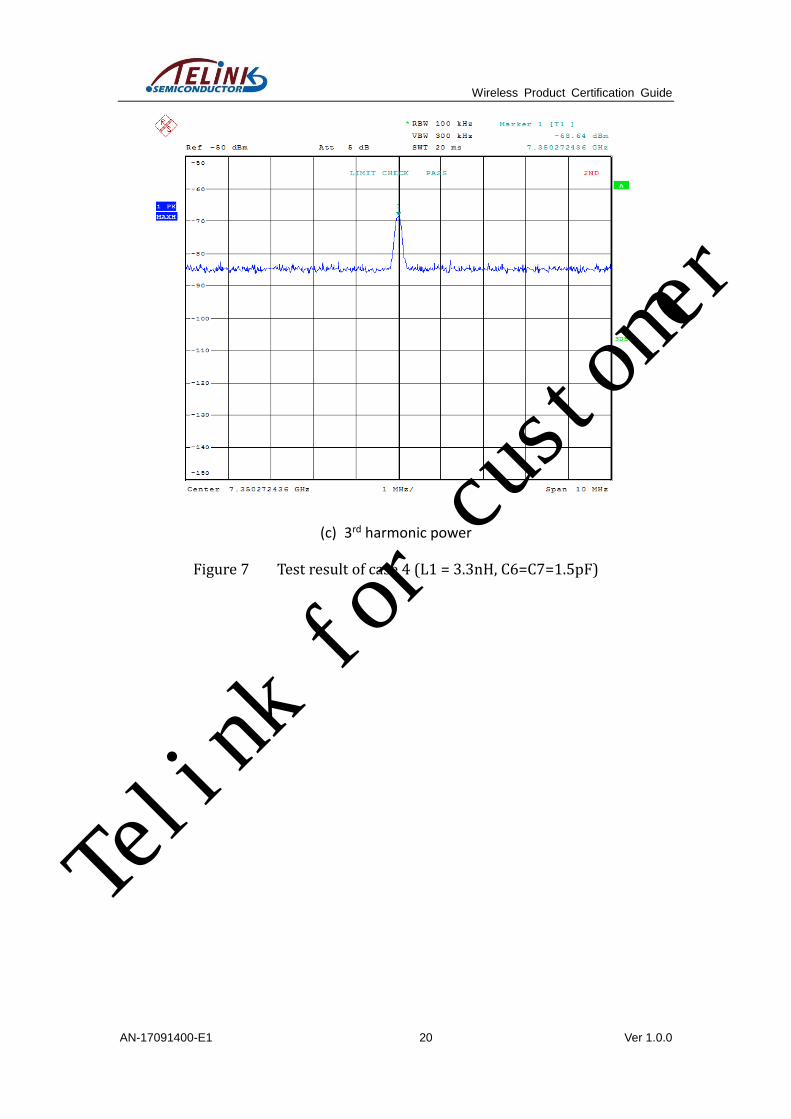
4 3.3nH 1.5pF 5.64dBm
Figure 7 (a)
-51.94dBm
Figure 7 (b)
-68.64dBm
Figure 7 (c)
5 2.2nH 1.5pF 4.32dBm
Figure 8 (a)
-51.85dBm
Figure 8 (b)
-67.83dBm
Figure 8 (c)
7.2.1 Test case 1: L1 = 2.2nH, C6=C7=3.3pF
(a) Tx power Telink for customer
Page 15
Wireless Product Certification Guide
AN-17091400-E1 14 Ver 1.0.0
(b) 2nd harmonic power
(c) 3rd harmonic power
Figure 4 Test result of case 1 (L1 = 2.2nH, C6=C7=3.3pF)
Telink for customer
Page 16
Wireless Product Certification Guide
AN-17091400-E1 15 Ver 1.0.0
7.2.2 Test case 2: L1 = 2.2nH, C6=C7=1pF
(a) Tx power
(b) 2nd harmonic power
Telink for customer
Page 17
Wireless Product Certification Guide
AN-17091400-E1 16 Ver 1.0.0
(c) 3rd harmonic power
Figure 5 Test result of case 2 (L1 = 2.2nH, C6=C7=1pF)
Telink for customer
Page 18
Wireless Product Certification Guide
AN-17091400-E1 17 Ver 1.0.0
7.2.3 Test case 3: L1 = 1nH, C6=C7=1.5pF
(a) Tx power
(b) 2nd harmonic power
Telink for customer
Page 19
Wireless Product Certification Guide
AN-17091400-E1 18 Ver 1.0.0
(c) 3rd harmonic power
Figure 6 Test result of case 3 (L1 = 1nH, C6=C7=1.5pF)
Telink for customer
Page 20
Wireless Product Certification Guide
AN-17091400-E1 19 Ver 1.0.0
7.2.4 Test case 4: L1 = 3.3nH, C6=C7=1.5pF
(a) Tx power
(b) 2nd harmonic power
Telink for customer
Page 21
Wireless Product Certification Guide
AN-17091400-E1 20 Ver 1.0.0
(c) 3rd harmonic power
Figure 7 Test result of case 4 (L1 = 3.3nH, C6=C7=1.5pF)
Telink for customer
Page 22
Wireless Product Certification Guide
AN-17091400-E1 21 Ver 1.0.0
7.2.5 Test case 5: L1 = 2.2nH, C6=C7=1.5pF
(a) Tx power
(b) 2nd harmonic power
Telink for customer
Page 23
Wireless Product Certification Guide
AN-17091400-E1 22 Ver 1.0.0
(c) 3rd harmonic power
Figure 8 Test result of case 5 (L1 = 2.2nH, C6=C7=1.5pF)
7.2.6 Conclusion
As test result above shows, it’s recommended to select 3.3nH/2.2nH and 1.5pF
as the L1, C6 and C7 values of the matching network for this DUT. The values can
ensure in-band loss low enough to pass all FCC items.
The filter component values recommended for FCC certification may vary
depending on the DUT used. Customers can follow similar steps to tune their own
boards correspondingly.
Telink for customer