Page 1
MAA; Reviewed:
SPOC 02/04/2015
Solution & Interoperability Test Lab Application Notes
©2015 Avaya Inc. All Rights Reserved.
1 of 61
EarthL_IPO9SBCE
Avaya Solution & Interoperability Test Lab
Application Notes for Configuring Avaya IP Office 9.0 and
Avaya Session Border Controller for Enterprise 6.3 to
support EarthLink SIP Trunking – Issue 1.0
Abstract
These Application Notes describe the procedures for configuring Session Initiation Protocol
(SIP) Trunking on an enterprise solution consisting of Avaya IP Office 9.0 and Avaya Session
Border Controller for Enterprise 6.3, to interoperate with EarthLink SIP Trunking.
EarthLink is a member of the Avaya DevConnect Service Provider program. The EarthLink
SIP Trunking service provides customers with PSTN access via a SIP trunk between the
enterprise and the EarthLink network, as an alternative to legacy analog or digital trunks. This
approach generally results in lower cost for the enterprise.
Readers should pay attention to Section 2, in particular the scope of testing as outlined in
Section 2.1 as well as the observations noted in Section 2.2, to ensure that their own use cases
are adequately covered by this scope and results.
Information in these Application Notes has been obtained through DevConnect compliance
testing and additional technical discussions. Testing was conducted via the DevConnect
Program at the Avaya Solution and Interoperability Test Lab.
Page 2
MAA; Reviewed:
SPOC 02/04/2015
Solution & Interoperability Test Lab Application Notes
©2015 Avaya Inc. All Rights Reserved.
2 of 61
EarthL_IPO9SBCE
1. Introduction These Application Notes describe the steps to configure Session Initiation Protocol (SIP)
trunking between the EarthLink SIP Trunking service and an Avaya SIP-enabled enterprise
solution. The Avaya solution consists of Avaya IP Office Release 9.0, Avaya Session Border
Controller for Enterprise (Avaya SBCE) Release 6.3 and various Avaya endpoints.
The EarthLink SIP Trunking service referenced within these Application Notes is designed for
business customers. Customers using this service with this Avaya enterprise solution are able to
place and receive PSTN calls via a broadband WAN connection and the SIP protocol. This
converged network solution is an alternative to traditional PSTN trunks such as analog and/or
ISDN-PRI.
2. General Test Approach and Test Results A simulated enterprise site containing all the Avaya equipment for the SIP-enabled solution was
installed at the Avaya Solution and Interoperability Lab. The enterprise site was configured to
connect to the EarthLink SIP Trunking service via a broadband connection.
The configuration shown in Figure 1 was used to exercise the features and functionality tests
listed in Section 2.1.
DevConnect Compliance Testing is conducted jointly by Avaya and DevConnect members. The
jointly-defined test plan focuses on exercising APIs and/or standards-based interfaces pertinent
to the interoperability of the tested products and their functionalities. DevConnect Compliance
Testing is not intended to substitute full product performance or feature testing performed by
DevConnect members, nor is it to be construed as an endorsement by Avaya of the suitability or
completeness of a DevConnect member’s solution.
Testing was performed with IP Office 500 v2 R9.0, but it also applies to IP Office Server Edition
R9.0. Note that IP Office Server Edition requires an Expansion IP Office 500 v2 R9.0 to support
analog or digital endpoints or trunks.
Page 3
MAA; Reviewed:
SPOC 02/04/2015
Solution & Interoperability Test Lab Application Notes
©2015 Avaya Inc. All Rights Reserved.
3 of 61
EarthL_IPO9SBCE
2.1. Interoperability Compliance Testing
To verify SIP trunking interoperability, the following features and functionality were covered
during the interoperability compliance test:
Response to SIP OPTIONS queries.
Incoming PSTN calls to various phone types. Phone types included SIP, H.323, digital
and analog telephones at the enterprise. All inbound PSTN calls were routed to the
enterprise across the SIP trunk from the service provider.
Outgoing PSTN calls from various phone types. Phone types included SIP, H.323,
digital, and analog telephones at the enterprise. All outbound PSTN calls were routed
from the enterprise across the SIP trunk to the service provider.
Inbound and outbound PSTN calls to/from Avaya IP Office Softphones.
Inbound and outbound PSTN calls to/from Avaya Flare® Experience for Windows
softphones.
Inbound and outbound PSTN calls to/from SIP remote workers using Avaya Flare®
Experience for Windows softphones.
Various call types including: local, long distance national, long distance international,
outbound toll free and local directory assistant.
Codecs G.729A and G.711MU
G.711 Fax.
Caller ID presentation and Caller ID restriction.
DTMF transmission using RFC 2833.
Voicemail navigation for inbound and outbound calls.
User features such as hold and resume, transfer, and conference.
Off-net call transfer, call forwarding and twinning.
The following functionality was not tested or it was not supported in the test configuration:
Inbound toll-free, Operator (0) and Operator-Assisted (0 + 10-digits) calls were not
supported in the testing environment.
Emergency calls (911) were supported but were not tested as part of the compliance test.
Page 4
MAA; Reviewed:
SPOC 02/04/2015
Solution & Interoperability Test Lab Application Notes
©2015 Avaya Inc. All Rights Reserved.
4 of 61
EarthL_IPO9SBCE
2.2. Test Results
Interoperability testing of the EarthLink SIP Trunking service was completed with successful
results for all test cases with the observations and limitations described below:
Outbound call to a PSTN number that is “Busy” - On outbound calls from an
enterprise extension to a PSTN telephone that is busy, the caller hears “busy” tone, but no
“486 Busy Here” error code is sent by EarthLink to the enterprise. This limitation had no
user impact during the test, it is listed here simply as an observation.
No matching codec on outbound call - On outbound calls using codecs that are not
supported by the service provider, EarthLink responds with “503 Service Unavailable”
instead of the expected “488 Not Acceptable Here”. This limitation had no user impact
during the test, it is listed here simply as an observation.
DTMF Tone Support – In the reference configuration, the Avaya IP Office was
configured to use RTP events for DTMF support, by selecting RFC2833 under DTMF
Support on the SIP Line/ VoIP tab. During testing, it was initially observed that
depending on the particular PSTN carrier in which the call arrived to EarthLink,
incoming calls to the enterprise occasionally showed in their SDP attributes of “inband”
DTMF support, while in other occasions they showed DTMF support as RTP events.
This inconsistency was reported to EarthLink. and resolved by configuration changes on
the EarthLink side. After these changes were made, all calls arrived to the IP Office
showing DTMF support as per RFC2833, using RTP events, payload type 101.
Blind Call Transfer of PSTN call to another PSTN endpoint, using REFER - On
PSTN calls that are blind transferred (transfer before answer) back to the network,
EarthLink responded to the REFER sent by the enterprise with “202 Accepted” followed
by a "491 Request Pending" embedded in a Notify message. The calls were transferred
successfully; however both trunks remain connected to IP Office for the complete
duration of the call. Consultative transfer (transfer after answer) of similar PSTN calls
worked properly. In this case, EarthLink sent a Notify containing a "200 OK", and the
two trunks to the IP Office were released.
Fax – T.38 fax is not supported by EarthLink. Fax was successfully tested using G711
pass-through mode.
SIP Header Manipulation – During the compliance test, EarthLink included on inbound
messages the “Alert-Info” and “Organization” headers. These headers had no
significance to the Avaya IP Office, and they were blocked in the Avaya SBCE by using
a Sigma Script. The script was additionally used to remove the “Remote-Address” header
used by the Avaya SBCE from outbound messages to the service provider. This header
has local significance only and should not be propagated on the SIP trunk to the service
provider.
2.3. Support
For technical support and contact information on the EarthLink SIP Trunking service offer, visit http://www.earthlinkbusiness.com/
Page 5
MAA; Reviewed:
SPOC 02/04/2015
Solution & Interoperability Test Lab Application Notes
©2015 Avaya Inc. All Rights Reserved.
5 of 61
EarthL_IPO9SBCE
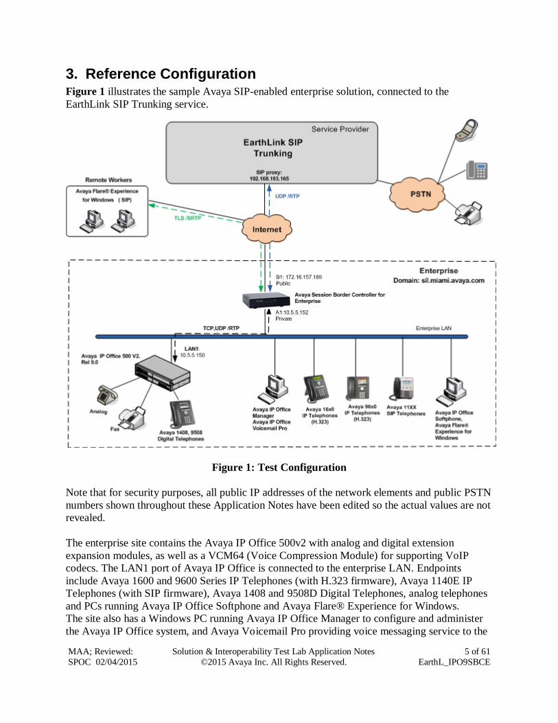
3. Reference Configuration Figure 1 illustrates the sample Avaya SIP-enabled enterprise solution, connected to the
EarthLink SIP Trunking service.
Figure 1: Test Configuration
Note that for security purposes, all public IP addresses of the network elements and public PSTN
numbers shown throughout these Application Notes have been edited so the actual values are not
revealed.
The enterprise site contains the Avaya IP Office 500v2 with analog and digital extension
expansion modules, as well as a VCM64 (Voice Compression Module) for supporting VoIP
codecs. The LAN1 port of Avaya IP Office is connected to the enterprise LAN. Endpoints
include Avaya 1600 and 9600 Series IP Telephones (with H.323 firmware), Avaya 1140E IP
Telephones (with SIP firmware), Avaya 1408 and 9508D Digital Telephones, analog telephones
and PCs running Avaya IP Office Softphone and Avaya Flare® Experience for Windows.
The site also has a Windows PC running Avaya IP Office Manager to configure and administer
the Avaya IP Office system, and Avaya Voicemail Pro providing voice messaging service to the
Page 6
MAA; Reviewed:
SPOC 02/04/2015
Solution & Interoperability Test Lab Application Notes
©2015 Avaya Inc. All Rights Reserved.
6 of 61
EarthL_IPO9SBCE
Avaya IP Office users. Mobile Twinning is configured for some of the Avaya IP Office users so
that calls to these users’ extensions will also ring and can be answered at the configured mobile
telephones.
Located at the edge of the enterprise, the Avaya SBCE has two physical interfaces. Interface B1
was used to connect to the public network, while interface A1 was used to connect to the private
enterprise infrastructure. All signaling and media traffic entering or leaving the enterprise flows
through the Avaya SBCE, in this way protecting the enterprise against any SIP-based attacks.
The Avaya SBCE also performs network address translation at both the IP and SIP layers.
Additionally, the reference configuration included the support for IP Office soft-clients in a
remote worker environment. This functionality was introduced with the software releases of
Avaya IP Office 9.0 and Avaya SBCE 6.2. A remote worker is a SIP endpoint that resides in the
untrusted network, registered to the IP Office at the enterprise via the Avaya SBCE. Remote
workers feature the same functionality as any other endpoint at the enterprise. The Avaya Flare®
Experience for Windows soft-client was used for this purpose. For security, remote workers used
Transport Layer Security (TLS) as the signaling protocol and Secure Real Time Protocol (SRTP)
for the media.
The configuration tasks required to support remote workers are beyond the scope of these
Application Notes; hence they are not discussed in this document. Consult [10] in the Additional
References section for more information on this topic.
In an actual customer configuration, the enterprise site may include additional network
components between the service provider and the Avaya IP Office system, such as routers or
data firewalls. A complete discussion of the configuration of these devices is beyond the scope of
these Application Notes. However, it should be noted that all SIP and RTP traffic between the
service provider and the Avaya IP Office system must be allowed to pass through these devices.
Page 7
MAA; Reviewed:
SPOC 02/04/2015
Solution & Interoperability Test Lab Application Notes
©2015 Avaya Inc. All Rights Reserved.
7 of 61
EarthL_IPO9SBCE
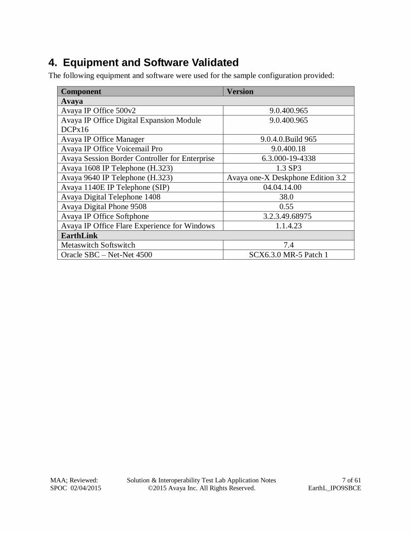
4. Equipment and Software Validated The following equipment and software were used for the sample configuration provided:
Component Version
Avaya
Avaya IP Office 500v2 9.0.400.965
Avaya IP Office Digital Expansion Module
DCPx16
9.0.400.965
Avaya IP Office Manager 9.0.4.0.Build 965
Avaya IP Office Voicemail Pro 9.0.400.18
Avaya Session Border Controller for Enterprise 6.3.000-19-4338
Avaya 1608 IP Telephone (H.323) 1.3 SP3
Avaya 9640 IP Telephone (H.323) Avaya one-X Deskphone Edition 3.2
Avaya 1140E IP Telephone (SIP) 04.04.14.00
Avaya Digital Telephone 1408 38.0
Avaya Digital Phone 9508 0.55
Avaya IP Office Softphone 3.2.3.49.68975
Avaya IP Office Flare Experience for Windows 1.1.4.23
EarthLink
Metaswitch Softswitch 7.4
Oracle SBC – Net-Net 4500 SCX6.3.0 MR-5 Patch 1
Page 8
MAA; Reviewed:
SPOC 02/04/2015
Solution & Interoperability Test Lab Application Notes
©2015 Avaya Inc. All Rights Reserved.
8 of 61
EarthL_IPO9SBCE
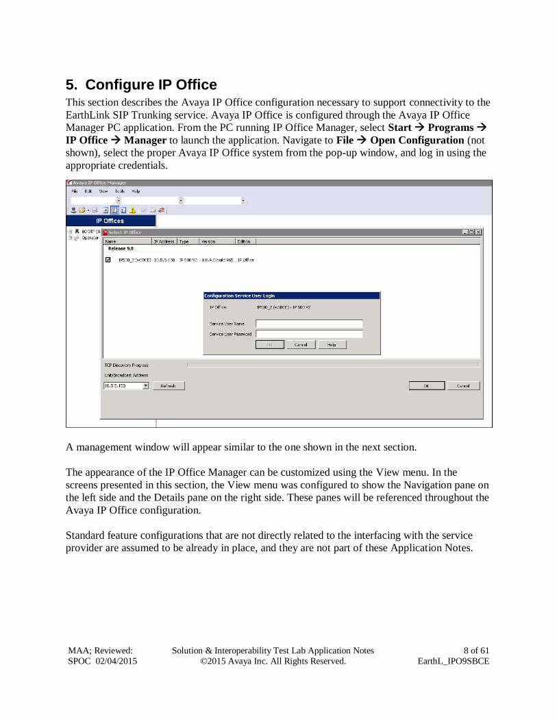
5. Configure IP Office This section describes the Avaya IP Office configuration necessary to support connectivity to the
EarthLink SIP Trunking service. Avaya IP Office is configured through the Avaya IP Office
Manager PC application. From the PC running IP Office Manager, select Start Programs
IP Office Manager to launch the application. Navigate to File Open Configuration (not
shown), select the proper Avaya IP Office system from the pop-up window, and log in using the
appropriate credentials.
A management window will appear similar to the one shown in the next section.
The appearance of the IP Office Manager can be customized using the View menu. In the
screens presented in this section, the View menu was configured to show the Navigation pane on
the left side and the Details pane on the right side. These panes will be referenced throughout the
Avaya IP Office configuration.
Standard feature configurations that are not directly related to the interfacing with the service
provider are assumed to be already in place, and they are not part of these Application Notes.
Page 9
MAA; Reviewed:
SPOC 02/04/2015
Solution & Interoperability Test Lab Application Notes
©2015 Avaya Inc. All Rights Reserved.
9 of 61
EarthL_IPO9SBCE
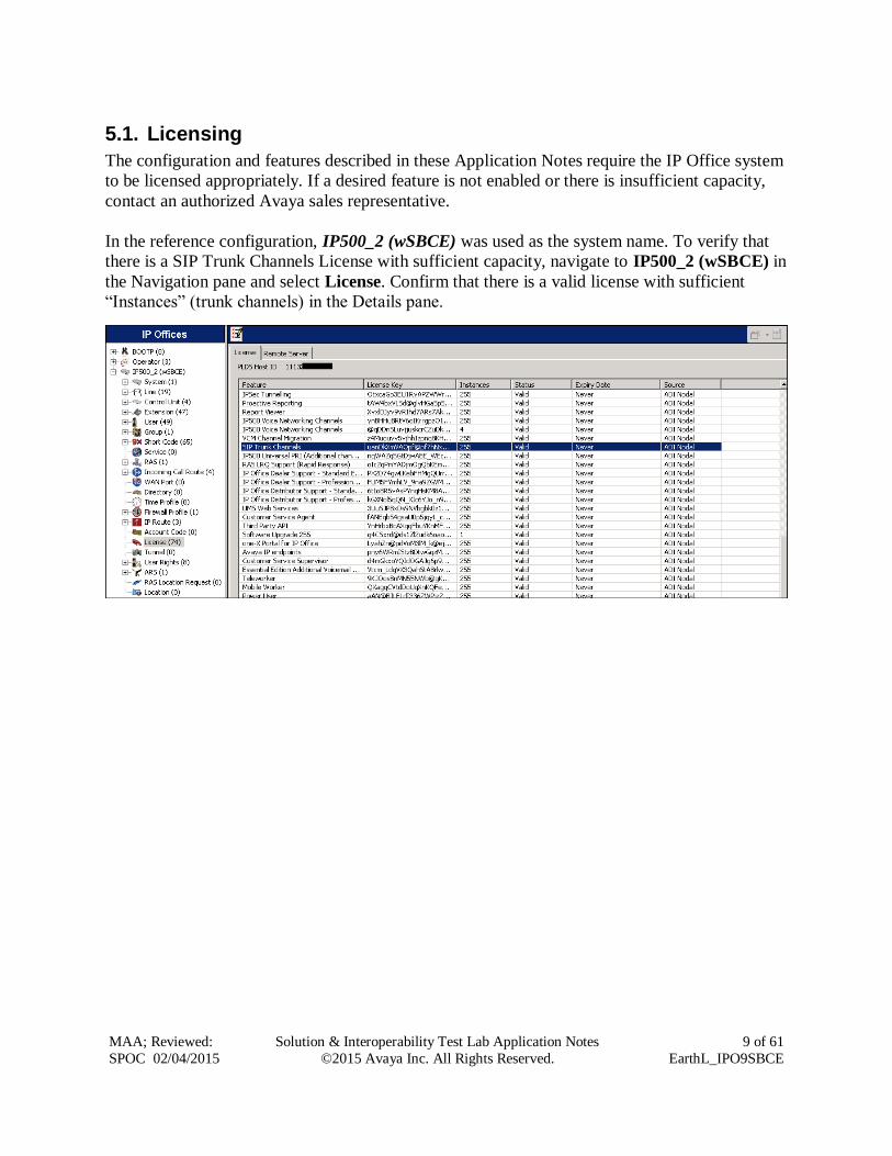
5.1. Licensing
The configuration and features described in these Application Notes require the IP Office system
to be licensed appropriately. If a desired feature is not enabled or there is insufficient capacity,
contact an authorized Avaya sales representative.
In the reference configuration, IP500_2 (wSBCE) was used as the system name. To verify that
there is a SIP Trunk Channels License with sufficient capacity, navigate to IP500_2 (wSBCE) in
the Navigation pane and select License. Confirm that there is a valid license with sufficient
“Instances” (trunk channels) in the Details pane.
Page 10
MAA; Reviewed:
SPOC 02/04/2015
Solution & Interoperability Test Lab Application Notes
©2015 Avaya Inc. All Rights Reserved.
10 of 61
EarthL_IPO9SBCE
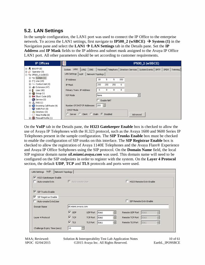
5.2. LAN Settings
In the sample configuration, the LAN1 port was used to connect the IP Office to the enterprise
network. To access the LAN1 settings, first navigate to IP500_2 (wSBCE) System (1) in the
Navigation pane and select the LAN1 LAN Settings tab in the Details pane. Set the IP
Address and IP Mask fields to the IP address and subnet mask assigned to the Avaya IP Office
LAN1 port. All other parameters should be set according to customer requirements.
On the VoIP tab in the Details pane, the H323 Gatekeeper Enable box is checked to allow the
use of Avaya IP Telephones with the H.323 protocol, such as the Avaya 1600 and 9600 Series IP
Telephones present in the sample configuration. The SIP Trunks Enable box must be checked
to enable the configuration of SIP trunks on this interface. The SIP Registrar Enable box is
checked to allow the registration of Avaya 1140E Telephones and the Avaya Flare® Experience
and Avaya IP Office Softphones using the SIP protocol. On the Domain Name field, the local
SIP registrar domain name sil.miami.avaya.com was used. This domain name will need to be
configured on the SIP endpoints in order to register with the system. On the Layer 4 Protocol
section, the default UDP, TCP and TLS protocols and ports were used.
Page 11
MAA; Reviewed:
SPOC 02/04/2015
Solution & Interoperability Test Lab Application Notes
©2015 Avaya Inc. All Rights Reserved.
11 of 61
EarthL_IPO9SBCE
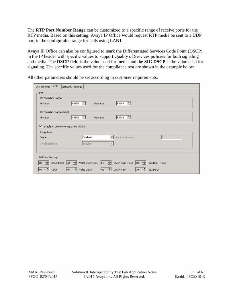
The RTP Port Number Range can be customized to a specific range of receive ports for the
RTP media. Based on this setting, Avaya IP Office would request RTP media be sent to a UDP
port in the configurable range for calls using LAN1.
Avaya IP Office can also be configured to mark the Differentiated Services Code Point (DSCP)
in the IP header with specific values to support Quality of Services policies for both signaling
and media. The DSCP field is the value used for media and the SIG DSCP is the value used for
signaling. The specific values used for the compliance test are shown in the example below.
All other parameters should be set according to customer requirements.
Page 12
MAA; Reviewed:
SPOC 02/04/2015
Solution & Interoperability Test Lab Application Notes
©2015 Avaya Inc. All Rights Reserved.
12 of 61
EarthL_IPO9SBCE
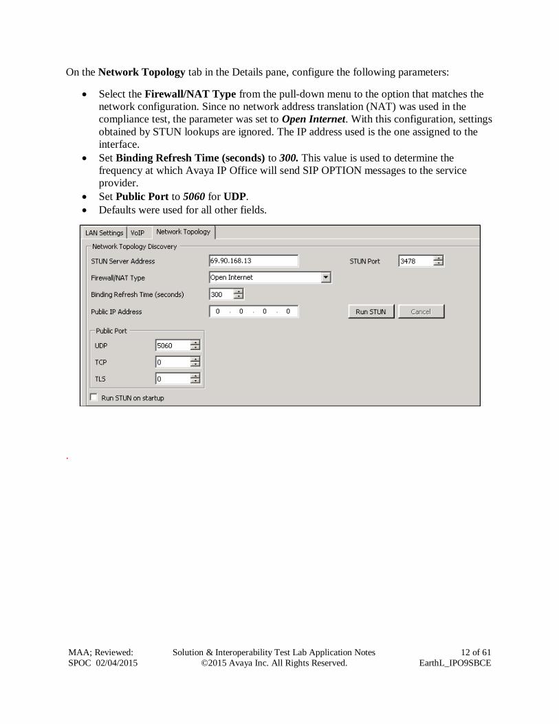
On the Network Topology tab in the Details pane, configure the following parameters:
Select the Firewall/NAT Type from the pull-down menu to the option that matches the
network configuration. Since no network address translation (NAT) was used in the
compliance test, the parameter was set to Open Internet. With this configuration, settings
obtained by STUN lookups are ignored. The IP address used is the one assigned to the
interface.
Set Binding Refresh Time (seconds) to 300. This value is used to determine the
frequency at which Avaya IP Office will send SIP OPTION messages to the service
provider.
Set Public Port to 5060 for UDP.
Defaults were used for all other fields.
.
Page 13
MAA; Reviewed:
SPOC 02/04/2015
Solution & Interoperability Test Lab Application Notes
©2015 Avaya Inc. All Rights Reserved.
13 of 61
EarthL_IPO9SBCE
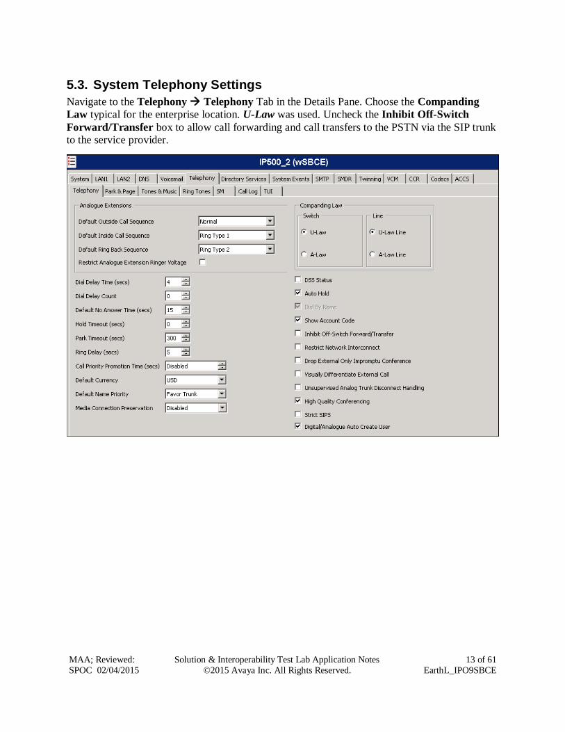
5.3. System Telephony Settings
Navigate to the Telephony Telephony Tab in the Details Pane. Choose the Companding
Law typical for the enterprise location. U-Law was used. Uncheck the Inhibit Off-Switch
Forward/Transfer box to allow call forwarding and call transfers to the PSTN via the SIP trunk
to the service provider.
Page 14
MAA; Reviewed:
SPOC 02/04/2015
Solution & Interoperability Test Lab Application Notes
©2015 Avaya Inc. All Rights Reserved.
14 of 61
EarthL_IPO9SBCE
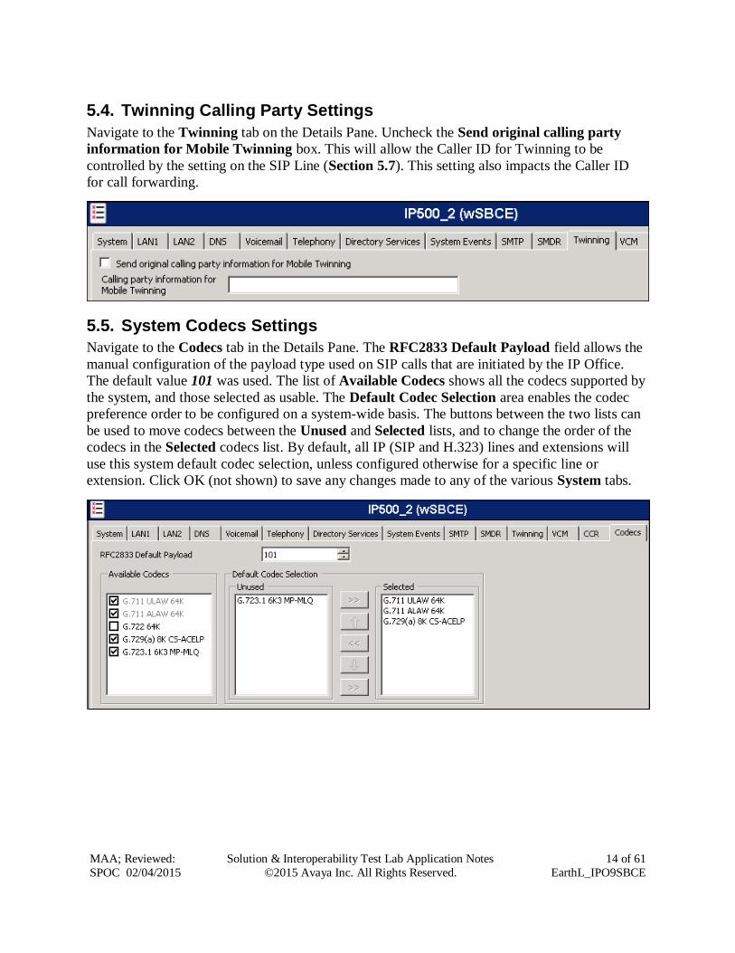
5.4. Twinning Calling Party Settings
Navigate to the Twinning tab on the Details Pane. Uncheck the Send original calling party
information for Mobile Twinning box. This will allow the Caller ID for Twinning to be
controlled by the setting on the SIP Line (Section 5.7). This setting also impacts the Caller ID
for call forwarding.
5.5. System Codecs Settings
Navigate to the Codecs tab in the Details Pane. The RFC2833 Default Payload field allows the
manual configuration of the payload type used on SIP calls that are initiated by the IP Office.
The default value 101 was used. The list of Available Codecs shows all the codecs supported by
the system, and those selected as usable. The Default Codec Selection area enables the codec
preference order to be configured on a system-wide basis. The buttons between the two lists can
be used to move codecs between the Unused and Selected lists, and to change the order of the
codecs in the Selected codecs list. By default, all IP (SIP and H.323) lines and extensions will
use this system default codec selection, unless configured otherwise for a specific line or
extension. Click OK (not shown) to save any changes made to any of the various System tabs.
Page 15
MAA; Reviewed:
SPOC 02/04/2015
Solution & Interoperability Test Lab Application Notes
©2015 Avaya Inc. All Rights Reserved.
15 of 61
EarthL_IPO9SBCE
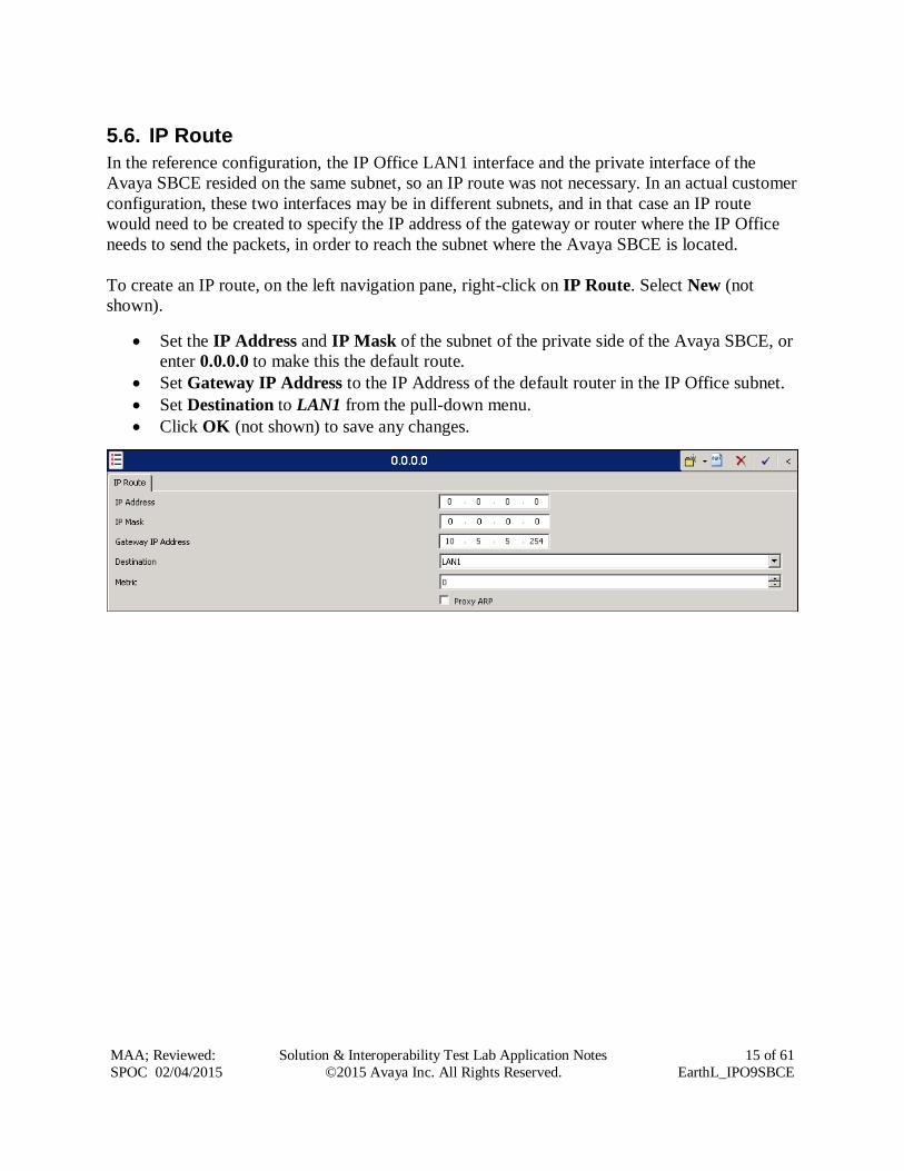
5.6. IP Route
In the reference configuration, the IP Office LAN1 interface and the private interface of the
Avaya SBCE resided on the same subnet, so an IP route was not necessary. In an actual customer
configuration, these two interfaces may be in different subnets, and in that case an IP route
would need to be created to specify the IP address of the gateway or router where the IP Office
needs to send the packets, in order to reach the subnet where the Avaya SBCE is located.
To create an IP route, on the left navigation pane, right-click on IP Route. Select New (not
shown).
Set the IP Address and IP Mask of the subnet of the private side of the Avaya SBCE, or
enter 0.0.0.0 to make this the default route.
Set Gateway IP Address to the IP Address of the default router in the IP Office subnet.
Set Destination to LAN1 from the pull-down menu.
Click OK (not shown) to save any changes.
Page 16
MAA; Reviewed:
SPOC 02/04/2015
Solution & Interoperability Test Lab Application Notes
©2015 Avaya Inc. All Rights Reserved.
16 of 61
EarthL_IPO9SBCE
5.7. Administer SIP Line
A SIP line is created to establish the SIP connection between the Avaya IP Office and the private
interface of the Avaya SBCE. This line will carry outbound and inbound traffic between to and
from the service provider. The recommended method for configuring a SIP Line is to use the
template associated with these Application Notes. The template is an .xml file that can be used
by IP Office Manager to create a SIP Line. Follow the steps in Section 5.7.1 to create the SIP
Line from the template.
Some items relevant to a specific customer environment are not included in the template or may
need to be updated after the SIP Line is created. Examples include the following:
IP addresses
SIP Credentials (if applicable)
SIP URI entries
Setting of the Use Network Topology Info field on the Transport tab.
Therefore, it is important that the SIP Line configuration be reviewed and updated if necessary
after the SIP Line is created via the template. The resulting SIP Line data can be verified against
the manual configuration shown in Sections 5.7.2 – 5.7.5.
Also, the following SIP Line settings are not supported on Basic Edition:
SIP Line – Originator number for forwarded and twinning calls
Transport – Second Explicit DNS Server
SIP Credentials – Registration Required
Alternatively, a SIP Line can be created manually. To do so, right-click Line in the Navigation
Pane and select New SIP Line. Then, follow the steps outlined in Sections 5.7.2 – 5.7.5.
Page 17
MAA; Reviewed:
SPOC 02/04/2015
Solution & Interoperability Test Lab Application Notes
©2015 Avaya Inc. All Rights Reserved.
17 of 61
EarthL_IPO9SBCE
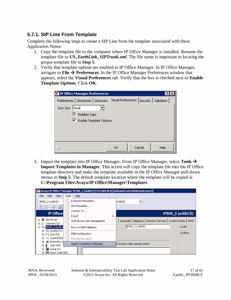
5.7.1. SIP Line From Template
Complete the following steps to create a SIP Line from the template associated with these
Application Notes:
1. Copy the template file to the computer where IP Office Manager is installed. Rename the
template file to US_EarthLink_SIPTrunk.xml. The file name is important in locating the
proper template file in Step 5.
2. Verify that template options are enabled in IP Office Manager. In IP Office Manager,
navigate to File Preferences. In the IP Office Manager Preferences window that
appears, select the Visual Preferences tab. Verify that the box is checked next to Enable
Template Options. Click OK.
3. Import the template into IP Office Manager. From IP Office Manager, select Tools
Import Templates in Manager. This action will copy the template file into the IP Office
template directory and make the template available in the IP Office Manager pull-down
menus in Step 5. The default template location where the template will be copied is
C:\Program Files\Avaya\IP Office\Manager\Templates.
Page 18
MAA; Reviewed:
SPOC 02/04/2015
Solution & Interoperability Test Lab Application Notes
©2015 Avaya Inc. All Rights Reserved.
18 of 61
EarthL_IPO9SBCE
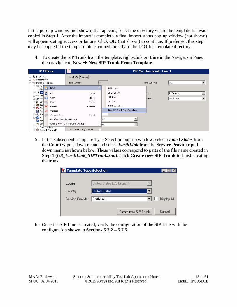
In the pop-up window (not shown) that appears, select the directory where the template file was
copied in Step 1. After the import is complete, a final import status pop-up window (not shown)
will appear stating success or failure. Click OK (not shown) to continue. If preferred, this step
may be skipped if the template file is copied directly to the IP Office template directory.
4. To create the SIP Trunk from the template, right-click on Line in the Navigation Pane,
then navigate to New New SIP Trunk From Template.
5. In the subsequent Template Type Selection pop-up window, select United States from
the Country pull-down menu and select EarthLink from the Service Provider pull-
down menu as shown below. These values correspond to parts of the file name created in
Step 1 (US_EarthLink_SIPTrunk.xml). Click Create new SIP Trunk to finish creating
the trunk.
6. Once the SIP Line is created, verify the configuration of the SIP Line with the
configuration shown in Sections 5.7.2 – 5.7.5.
Page 19
MAA; Reviewed:
SPOC 02/04/2015
Solution & Interoperability Test Lab Application Notes
©2015 Avaya Inc. All Rights Reserved.
19 of 61
EarthL_IPO9SBCE
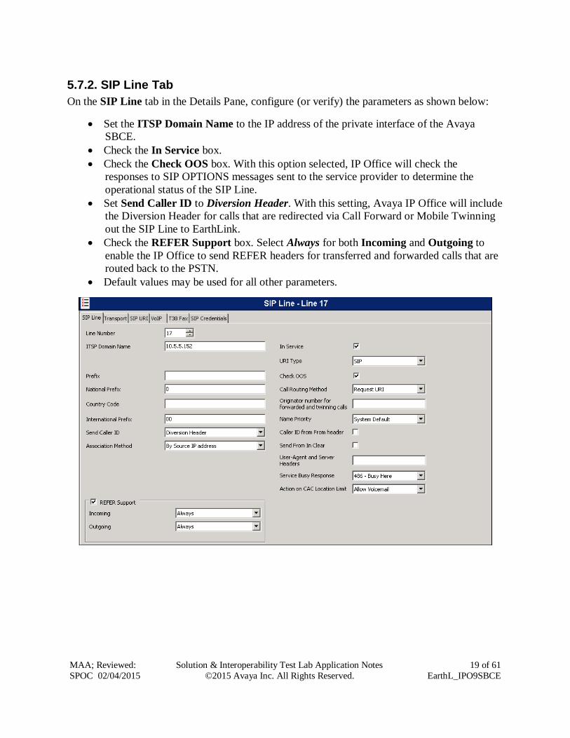
5.7.2. SIP Line Tab
On the SIP Line tab in the Details Pane, configure (or verify) the parameters as shown below:
Set the ITSP Domain Name to the IP address of the private interface of the Avaya
SBCE.
Check the In Service box.
Check the Check OOS box. With this option selected, IP Office will check the
responses to SIP OPTIONS messages sent to the service provider to determine the
operational status of the SIP Line.
Set Send Caller ID to Diversion Header. With this setting, Avaya IP Office will include
the Diversion Header for calls that are redirected via Call Forward or Mobile Twinning
out the SIP Line to EarthLink.
Check the REFER Support box. Select Always for both Incoming and Outgoing to
enable the IP Office to send REFER headers for transferred and forwarded calls that are
routed back to the PSTN.
Default values may be used for all other parameters.
Page 20
MAA; Reviewed:
SPOC 02/04/2015
Solution & Interoperability Test Lab Application Notes
©2015 Avaya Inc. All Rights Reserved.
20 of 61
EarthL_IPO9SBCE
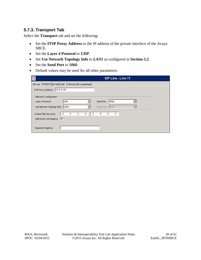
5.7.3. Transport Tab
Select the Transport tab and set the following:
Set the ITSP Proxy Address to the IP address of the private interface of the Avaya
SBCE.
Set the Layer 4 Protocol to UDP.
Set Use Network Topology Info to LAN1 as configured in Section 5.2.
Set the Send Port to 5060.
Default values may be used for all other parameters.
Page 21
MAA; Reviewed:
SPOC 02/04/2015
Solution & Interoperability Test Lab Application Notes
©2015 Avaya Inc. All Rights Reserved.
21 of 61
EarthL_IPO9SBCE
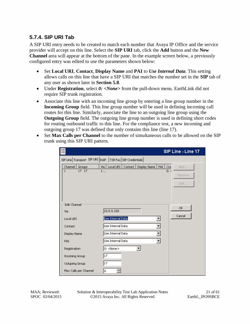
5.7.4. SIP URI Tab
A SIP URI entry needs to be created to match each number that Avaya IP Office and the service
provider will accept on this line. Select the SIP URI tab, click the Add button and the New
Channel area will appear at the bottom of the pane. In the example screen below, a previously
configured entry was edited to use the parameters shown below:
Set Local URI, Contact, Display Name and PAI to Use Internal Data. This setting
allows calls on this line that have a SIP URI that matches the number set in the SIP tab of
any user as shown later in Section 5.8.
Under Registration, select 0: <None> from the pull-down menu. EarthLink did not
require SIP trunk registration.
Associate this line with an incoming line group by entering a line group number in the
Incoming Group field. This line group number will be used in defining incoming call
routes for this line. Similarly, associate the line to an outgoing line group using the
Outgoing Group field. The outgoing line group number is used in defining short codes
for routing outbound traffic to this line. For the compliance test, a new incoming and
outgoing group 17 was defined that only contains this line (line 17).
Set Max Calls per Channel to the number of simultaneous calls to be allowed on the SIP
trunk using this SIP URI pattern.
Page 22
MAA; Reviewed:
SPOC 02/04/2015
Solution & Interoperability Test Lab Application Notes
©2015 Avaya Inc. All Rights Reserved.
22 of 61
EarthL_IPO9SBCE
Additional SIP URIs may be required to allow inbound calls to numbers not associated with a
user, such as a short code. These URIs are created in the same manner as shown previously,
with the exception that the incoming DID number is entered directly in the Local URI, Contact,
and Display Name fields, and only the Incoming Group needs to be associated to the SIP line.
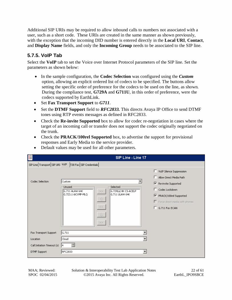
5.7.5. VoIP Tab
Select the VoIP tab to set the Voice over Internet Protocol parameters of the SIP line. Set the
parameters as shown below:
In the sample configuration, the Codec Selection was configured using the Custom
option, allowing an explicit ordered list of codecs to be specified. The buttons allow
setting the specific order of preference for the codecs to be used on the line, as shown.
During the compliance test, G729A and G711U, in this order of preference, were the
codecs supported by EarthLink.
Set Fax Transport Support to G711.
Set the DTMF Support field to RFC2833. This directs Avaya IP Office to send DTMF
tones using RTP events messages as defined in RFC2833.
Check the Re-invite Supported box to allow for codec re-negotiation in cases where the
target of an incoming call or transfer does not support the codec originally negotiated on
the trunk.
Check the PRACK/100rel Supported box, to advertise the support for provisional
responses and Early Media to the service provider.
Default values may be used for all other parameters.
Page 23
MAA; Reviewed:
SPOC 02/04/2015
Solution & Interoperability Test Lab Application Notes
©2015 Avaya Inc. All Rights Reserved.
23 of 61
EarthL_IPO9SBCE
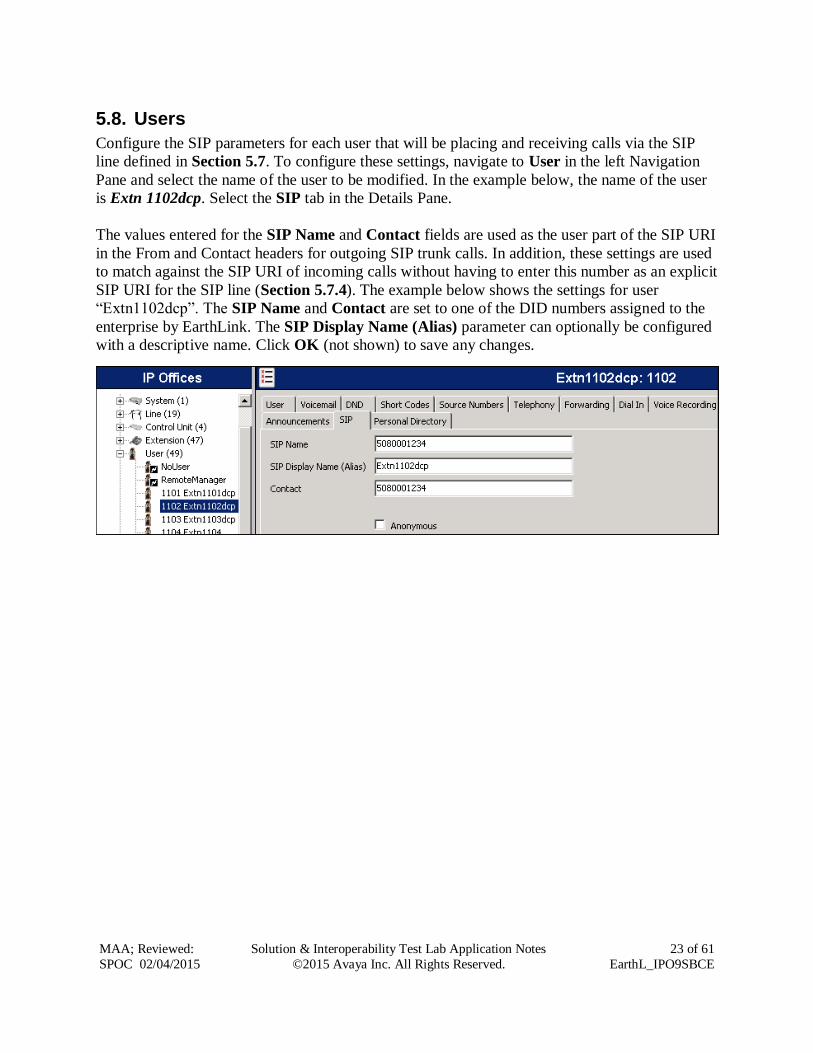
5.8. Users
Configure the SIP parameters for each user that will be placing and receiving calls via the SIP
line defined in Section 5.7. To configure these settings, navigate to User in the left Navigation
Pane and select the name of the user to be modified. In the example below, the name of the user
is Extn 1102dcp. Select the SIP tab in the Details Pane.
The values entered for the SIP Name and Contact fields are used as the user part of the SIP URI
in the From and Contact headers for outgoing SIP trunk calls. In addition, these settings are used
to match against the SIP URI of incoming calls without having to enter this number as an explicit
SIP URI for the SIP line (Section 5.7.4). The example below shows the settings for user
“Extn1102dcp”. The SIP Name and Contact are set to one of the DID numbers assigned to the
enterprise by EarthLink. The SIP Display Name (Alias) parameter can optionally be configured
with a descriptive name. Click OK (not shown) to save any changes.
Page 24
MAA; Reviewed:
SPOC 02/04/2015
Solution & Interoperability Test Lab Application Notes
©2015 Avaya Inc. All Rights Reserved.
24 of 61
EarthL_IPO9SBCE
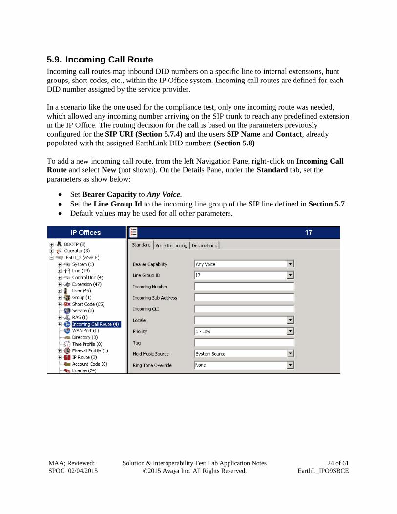
5.9. Incoming Call Route
Incoming call routes map inbound DID numbers on a specific line to internal extensions, hunt
groups, short codes, etc., within the IP Office system. Incoming call routes are defined for each
DID number assigned by the service provider.
In a scenario like the one used for the compliance test, only one incoming route was needed,
which allowed any incoming number arriving on the SIP trunk to reach any predefined extension
in the IP Office. The routing decision for the call is based on the parameters previously
configured for the SIP URI (Section 5.7.4) and the users SIP Name and Contact, already
populated with the assigned EarthLink DID numbers (Section 5.8)
To add a new incoming call route, from the left Navigation Pane, right-click on Incoming Call
Route and select New (not shown). On the Details Pane, under the Standard tab, set the
parameters as show below:
Set Bearer Capacity to Any Voice.
Set the Line Group Id to the incoming line group of the SIP line defined in Section 5.7.
Default values may be used for all other parameters.
Page 25
MAA; Reviewed:
SPOC 02/04/2015
Solution & Interoperability Test Lab Application Notes
©2015 Avaya Inc. All Rights Reserved.
25 of 61
EarthL_IPO9SBCE
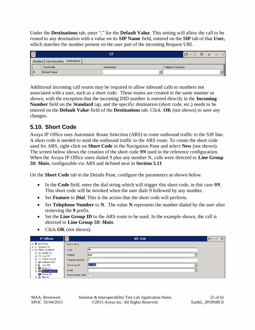
Under the Destinations tab, enter “.” for the Default Value. This setting will allow the call to be
routed to any destination with a value on its SIP Name field, entered on the SIP tab of that User,
which matches the number present on the user part of the incoming Request URI.
Additional incoming call routes may be required to allow inbound calls to numbers not
associated with a user, such as a short code. These routes are created in the same manner as
shown, with the exception that the incoming DID number is entered directly in the Incoming
Number field on the Standard tap, and the specific destination (short code, etc.) needs to be
entered on the Default Value field of the Destinations tab. Click OK (not shown) to save any
changes.
5.10. Short Code
Avaya IP Office uses Automatic Route Selection (ARS) to route outbound traffic to the SIP line.
A short code is needed to send the outbound traffic to the ARS route. To create the short code
used for ARS, right-click on Short Code in the Navigation Pane and select New (not shown).
The screen below shows the creation of the short code 9N used in the reference configuration.
When the Avaya IP Office users dialed 9 plus any number N, calls were directed to Line Group
50: Main, configurable via ARS and defined next in Section 5.11
On the Short Code tab in the Details Pane, configure the parameters as shown below.
In the Code field, enter the dial string which will trigger this short code, in this case 9N.
This short code will be invoked when the user dials 9 followed by any number.
Set Feature to Dial. This is the action that the short code will perform.
Set Telephone Number to N. The value N represents the number dialed by the user after
removing the 9 prefix.
Set the Line Group ID to the ARS route to be used. In the example shown, the call is
directed to Line Group 50: Main.
Click OK (not shown).
Page 26
MAA; Reviewed:
SPOC 02/04/2015
Solution & Interoperability Test Lab Application Notes
©2015 Avaya Inc. All Rights Reserved.
26 of 61
EarthL_IPO9SBCE
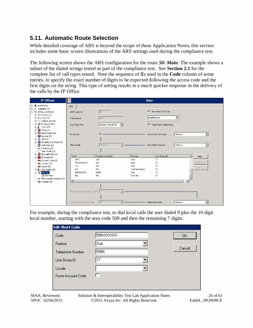
5.11. Automatic Route Selection
While detailed coverage of ARS is beyond the scope of these Application Notes, this section
includes some basic screen illustrations of the ARS settings used during the compliance test.
The following screen shows the ARS configuration for the route 50: Main. The example shows a
subset of the dialed strings tested as part of the compliance test. See Section 2.1 for the
complete list of call types tested. Note the sequence of Xs used in the Code column of some
entries, to specify the exact number of digits to be expected following the access code and the
first digits on the string. This type of setting results in a much quicker response in the delivery of
the calls by the IP Office.
For example, during the compliance test, to dial local calls the user dialed 9 plus the 10 digit
local number, starting with the area code 508 and then the remaining 7 digits.
Page 27
MAA; Reviewed:
SPOC 02/04/2015
Solution & Interoperability Test Lab Application Notes
©2015 Avaya Inc. All Rights Reserved.
27 of 61
EarthL_IPO9SBCE
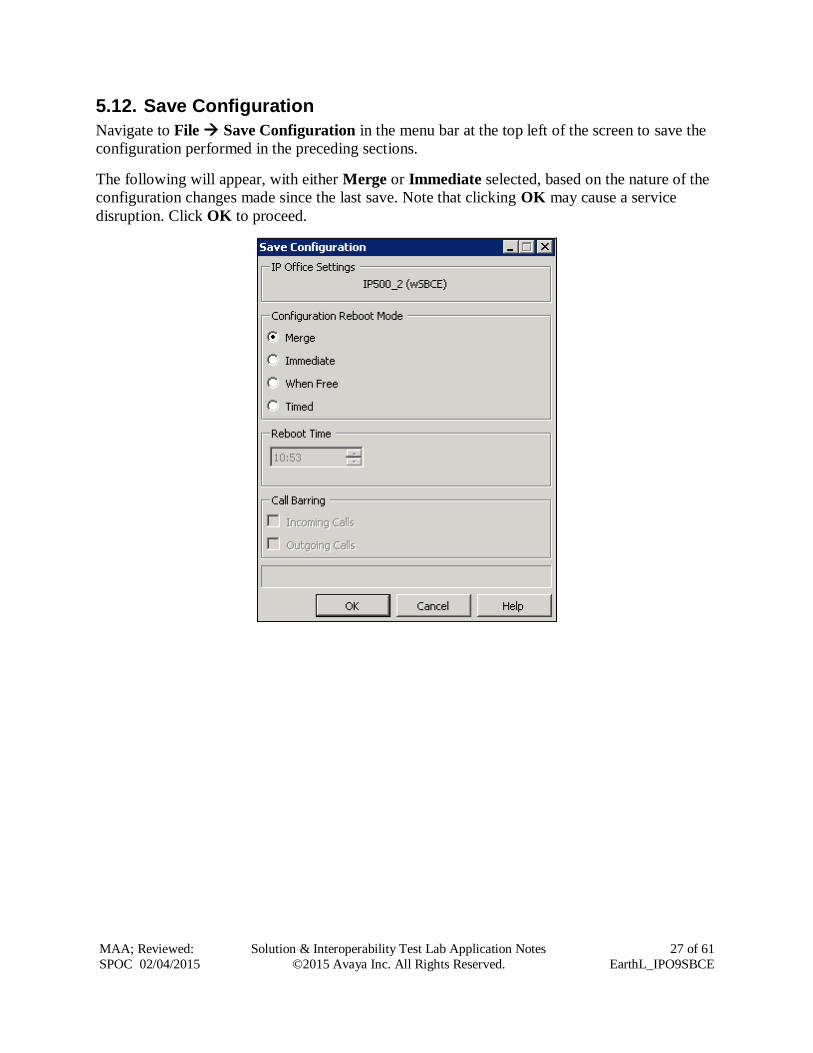
5.12. Save Configuration
Navigate to File Save Configuration in the menu bar at the top left of the screen to save the
configuration performed in the preceding sections.
The following will appear, with either Merge or Immediate selected, based on the nature of the
configuration changes made since the last save. Note that clicking OK may cause a service
disruption. Click OK to proceed.
Page 28
MAA; Reviewed:
SPOC 02/04/2015
Solution & Interoperability Test Lab Application Notes
©2015 Avaya Inc. All Rights Reserved.
28 of 61
EarthL_IPO9SBCE
6. Configure Avaya Session Border Controller for Enterprise This section describes the configuration of the Avaya SBCE. It is assumed that the initial
installation of the Avaya SBCE, the assignment of the management interface IP Address and
license installation have already been completed; hence these tasks are not covered in these
Application Notes. For more information on the installation and initial provisioning of the Avaya
SBCE consult the Avaya SBCE documentation in the Additional References section.
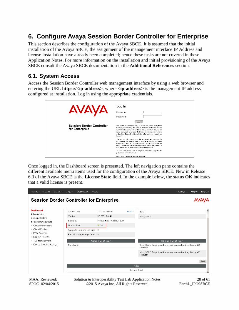
6.1. System Access
Access the Session Border Controller web management interface by using a web browser and
entering the URL https://<ip-address>, where <ip-address> is the management IP address
configured at installation. Log in using the appropriate credentials.
Once logged in, the Dashboard screen is presented. The left navigation pane contains the
different available menu items used for the configuration of the Avaya SBCE. New in Release
6.3 of the Avaya SBCE is the License State field. In the example below, the status OK indicates
that a valid license is present.
Page 29
MAA; Reviewed:
SPOC 02/04/2015
Solution & Interoperability Test Lab Application Notes
©2015 Avaya Inc. All Rights Reserved.
29 of 61
EarthL_IPO9SBCE
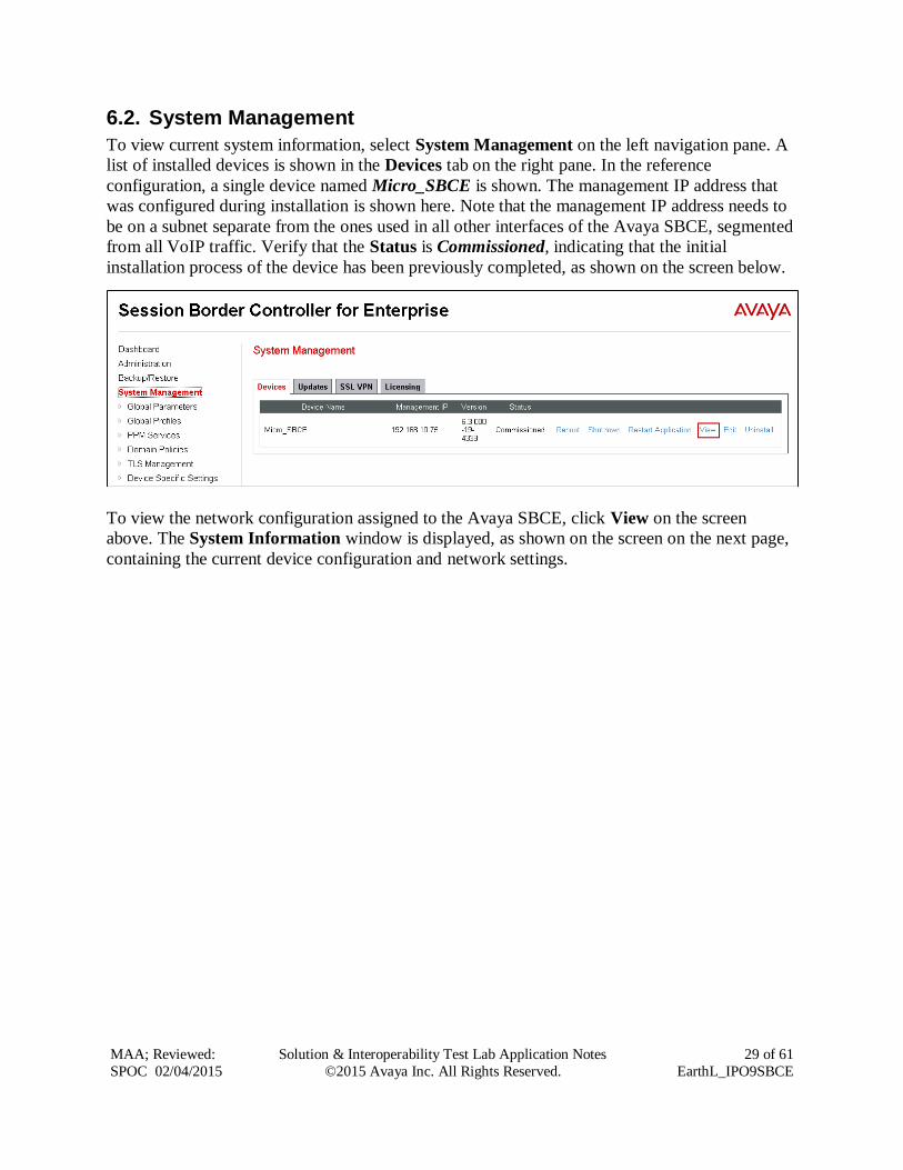
6.2. System Management
To view current system information, select System Management on the left navigation pane. A
list of installed devices is shown in the Devices tab on the right pane. In the reference
configuration, a single device named Micro_SBCE is shown. The management IP address that
was configured during installation is shown here. Note that the management IP address needs to
be on a subnet separate from the ones used in all other interfaces of the Avaya SBCE, segmented
from all VoIP traffic. Verify that the Status is Commissioned, indicating that the initial
installation process of the device has been previously completed, as shown on the screen below.
To view the network configuration assigned to the Avaya SBCE, click View on the screen
above. The System Information window is displayed, as shown on the screen on the next page,
containing the current device configuration and network settings.
Page 30
MAA; Reviewed:
SPOC 02/04/2015
Solution & Interoperability Test Lab Application Notes
©2015 Avaya Inc. All Rights Reserved.
30 of 61
EarthL_IPO9SBCE
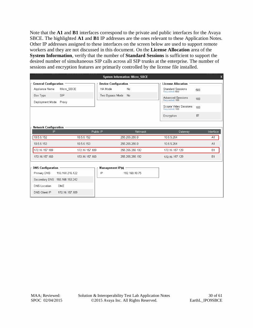
Note that the A1 and B1 interfaces correspond to the private and public interfaces for the Avaya
SBCE. The highlighted A1 and B1 IP addresses are the ones relevant to these Application Notes.
Other IP addresses assigned to these interfaces on the screen below are used to support remote
workers and they are not discussed in this document. On the License Allocation area of the
System Information, verify that the number of Standard Sessions is sufficient to support the
desired number of simultaneous SIP calls across all SIP trunks at the enterprise. The number of
sessions and encryption features are primarily controlled by the license file installed.
Page 31
MAA; Reviewed:
SPOC 02/04/2015
Solution & Interoperability Test Lab Application Notes
©2015 Avaya Inc. All Rights Reserved.
31 of 61
EarthL_IPO9SBCE
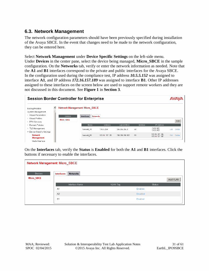
6.3. Network Management
The network configuration parameters should have been previously specified during installation
of the Avaya SBCE. In the event that changes need to be made to the network configuration,
they can be entered here.
Select Network Management under Device Specific Settings on the left-side menu.
Under Devices in the center pane, select the device being managed, Micro_SBCE in the sample
configuration. On the Networks tab, verify or enter the network information as needed. Note that
the A1 and B1 interfaces correspond to the private and public interfaces for the Avaya SBCE.
In the configuration used during the compliance test, IP address 10.5.5.152 was assigned to
interface A1, and IP address 172.16.157.189 was assigned to interface B1. Other IP addresses
assigned to these interfaces on the screen below are used to support remote workers and they are
not discussed in this document. See Figure 1 in Section 3.
On the Interfaces tab, verify the Status is Enabled for both the A1 and B1 interfaces. Click the
buttons if necessary to enable the interfaces.
Page 32
MAA; Reviewed:
SPOC 02/04/2015
Solution & Interoperability Test Lab Application Notes
©2015 Avaya Inc. All Rights Reserved.
32 of 61
EarthL_IPO9SBCE
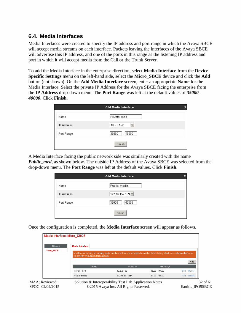
6.4. Media Interfaces
Media Interfaces were created to specify the IP address and port range in which the Avaya SBCE
will accept media streams on each interface. Packets leaving the interfaces of the Avaya SBCE
will advertise this IP address, and one of the ports in this range as the listening IP address and
port in which it will accept media from the Call or the Trunk Server.
To add the Media Interface in the enterprise direction, select Media Interface from the Device
Specific Settings menu on the left-hand side, select the Micro_SBCE device and click the Add
button (not shown). On the Add Media Interface screen, enter an appropriate Name for the
Media Interface. Select the private IP Address for the Avaya SBCE facing the enterprise from
the IP Address drop-down menu. The Port Range was left at the default values of 35000-
40000. Click Finish.
A Media Interface facing the public network side was similarly created with the name
Public_med, as shown below. The outside IP Address of the Avaya SBCE was selected from the
drop-down menu. The Port Range was left at the default values. Click Finish.
Once the configuration is completed, the Media Interface screen will appear as follows.
Page 33
MAA; Reviewed:
SPOC 02/04/2015
Solution & Interoperability Test Lab Application Notes
©2015 Avaya Inc. All Rights Reserved.
33 of 61
EarthL_IPO9SBCE
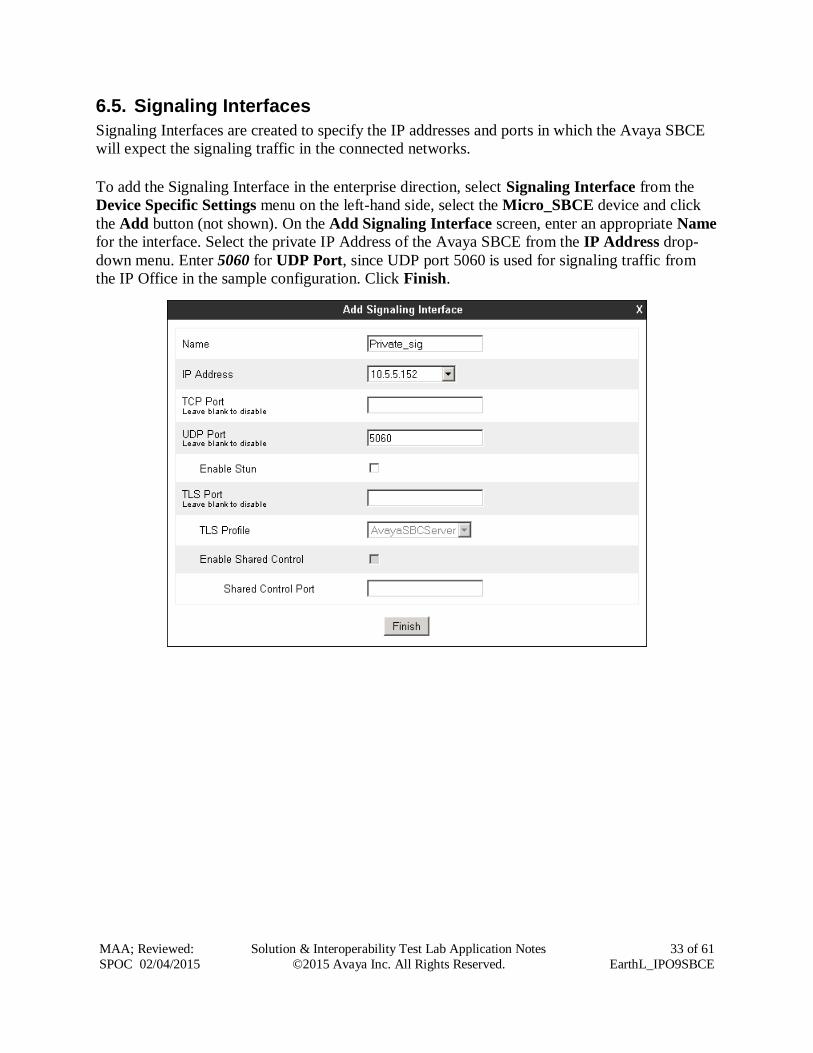
6.5. Signaling Interfaces
Signaling Interfaces are created to specify the IP addresses and ports in which the Avaya SBCE
will expect the signaling traffic in the connected networks.
To add the Signaling Interface in the enterprise direction, select Signaling Interface from the
Device Specific Settings menu on the left-hand side, select the Micro_SBCE device and click
the Add button (not shown). On the Add Signaling Interface screen, enter an appropriate Name
for the interface. Select the private IP Address of the Avaya SBCE from the IP Address drop-
down menu. Enter 5060 for UDP Port, since UDP port 5060 is used for signaling traffic from
the IP Office in the sample configuration. Click Finish.
Page 34
MAA; Reviewed:
SPOC 02/04/2015
Solution & Interoperability Test Lab Application Notes
©2015 Avaya Inc. All Rights Reserved.
34 of 61
EarthL_IPO9SBCE
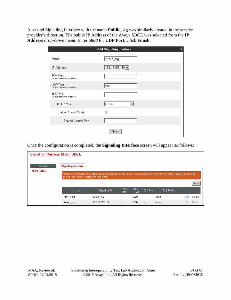
A second Signaling Interface with the name Public_sig was similarly created in the service
provider’s direction. The public IP Address of the Avaya SBCE was selected from the IP
Address drop-down menu. Enter 5060 for UDP Port. Click Finish.
Once the configuration is completed, the Signaling Interface screen will appear as follows:
Page 35
MAA; Reviewed:
SPOC 02/04/2015
Solution & Interoperability Test Lab Application Notes
©2015 Avaya Inc. All Rights Reserved.
35 of 61
EarthL_IPO9SBCE
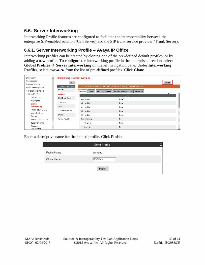
6.6. Server Interworking
Interworking Profile features are configured to facilitate the interoperability between the
enterprise SIP-enabled solution (Call Server) and the SIP trunk service provider (Trunk Server).
6.6.1. Server Interworking Profile – Avaya IP Office
Interworking profiles can be created by cloning one of the pre-defined default profiles, or by
adding a new profile. To configure the interworking profile in the enterprise direction, select
Global Profiles Server Interworking on the left navigation pane. Under Interworking
Profiles, select avaya-ru from the list of pre-defined profiles. Click Clone.
Enter a descriptive name for the cloned profile. Click Finish.
Page 36
MAA; Reviewed:
SPOC 02/04/2015
Solution & Interoperability Test Lab Application Notes
©2015 Avaya Inc. All Rights Reserved.
36 of 61
EarthL_IPO9SBCE
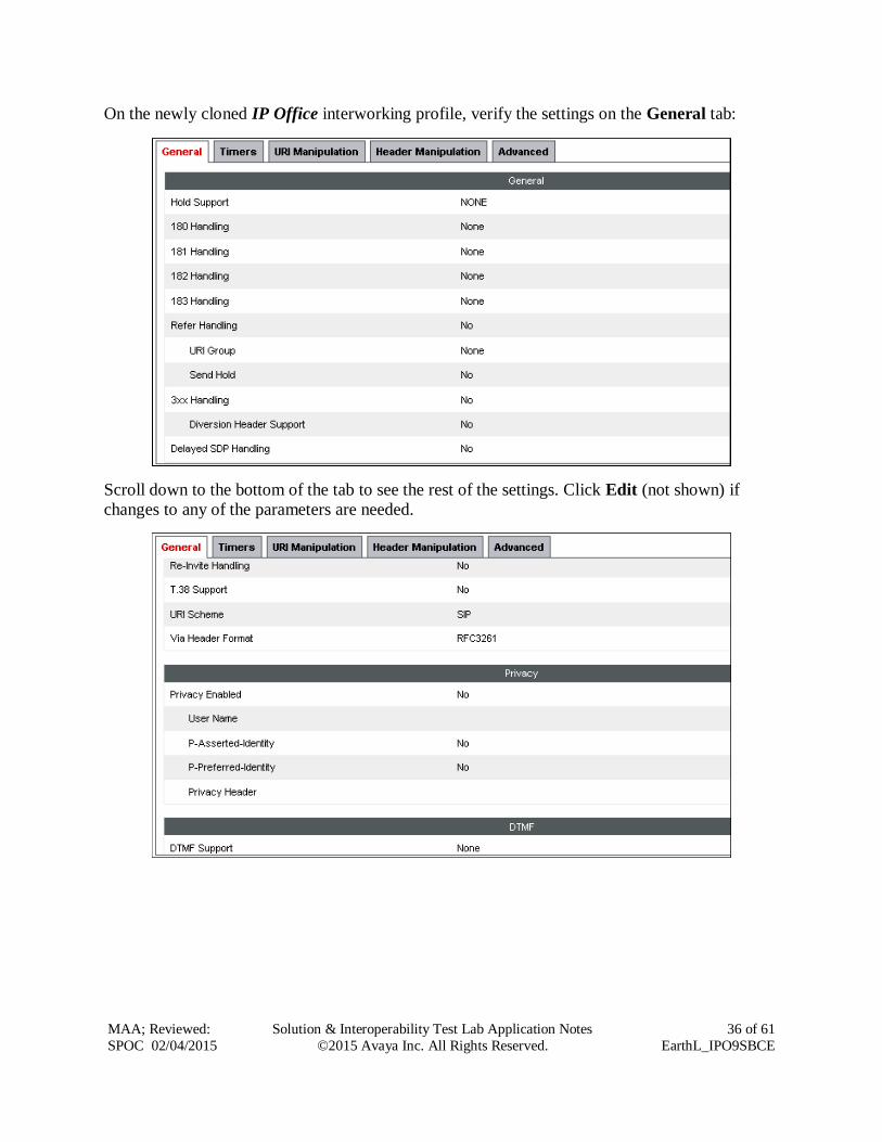
On the newly cloned IP Office interworking profile, verify the settings on the General tab:
Scroll down to the bottom of the tab to see the rest of the settings. Click Edit (not shown) if
changes to any of the parameters are needed.
Page 37
MAA; Reviewed:
SPOC 02/04/2015
Solution & Interoperability Test Lab Application Notes
©2015 Avaya Inc. All Rights Reserved.
37 of 61
EarthL_IPO9SBCE
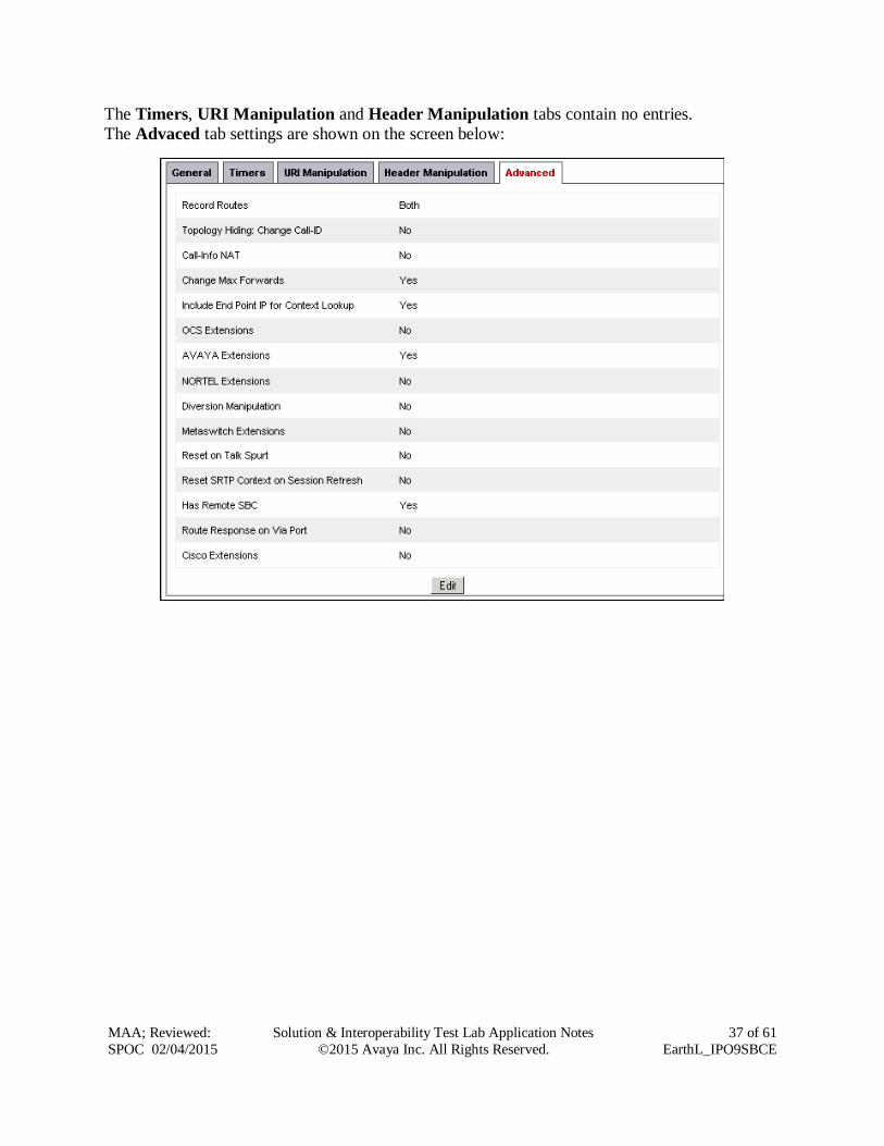
The Timers, URI Manipulation and Header Manipulation tabs contain no entries.
The Advaced tab settings are shown on the screen below:
Page 38
MAA; Reviewed:
SPOC 02/04/2015
Solution & Interoperability Test Lab Application Notes
©2015 Avaya Inc. All Rights Reserved.
38 of 61
EarthL_IPO9SBCE
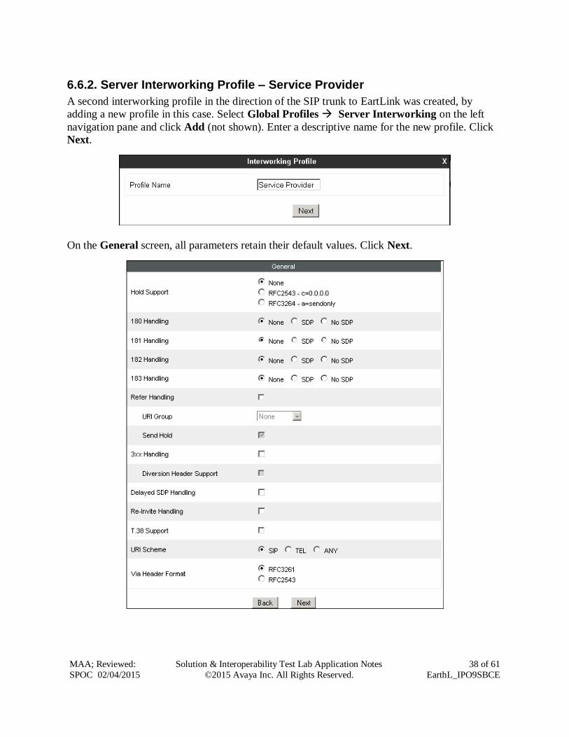
6.6.2. Server Interworking Profile – Service Provider
A second interworking profile in the direction of the SIP trunk to EartLink was created, by
adding a new profile in this case. Select Global Profiles Server Interworking on the left
navigation pane and click Add (not shown). Enter a descriptive name for the new profile. Click
Next.
On the General screen, all parameters retain their default values. Click Next.
Page 39
MAA; Reviewed:
SPOC 02/04/2015
Solution & Interoperability Test Lab Application Notes
©2015 Avaya Inc. All Rights Reserved.
39 of 61
EarthL_IPO9SBCE
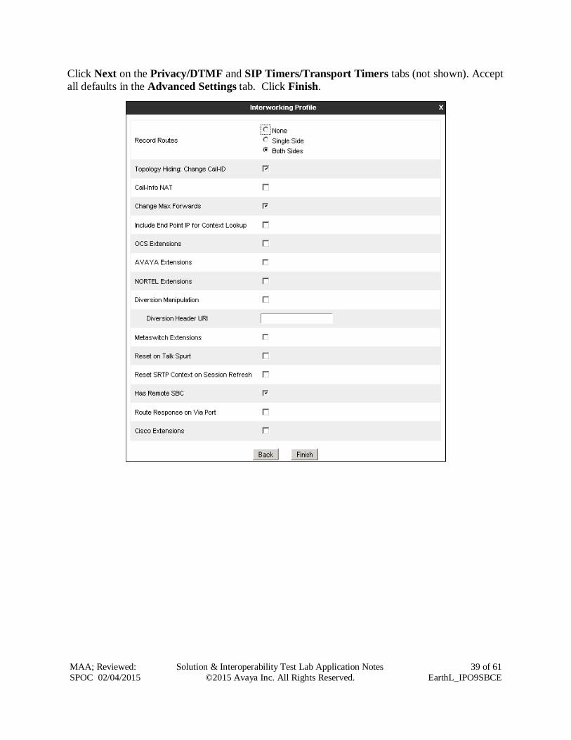
Click Next on the Privacy/DTMF and SIP Timers/Transport Timers tabs (not shown). Accept
all defaults in the Advanced Settings tab. Click Finish.
Page 40
MAA; Reviewed:
SPOC 02/04/2015
Solution & Interoperability Test Lab Application Notes
©2015 Avaya Inc. All Rights Reserved.
40 of 61
EarthL_IPO9SBCE
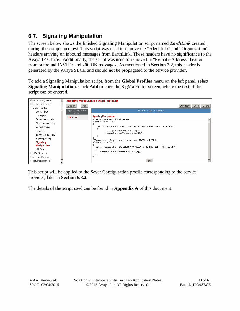
6.7. Signaling Manipulation
The screen below shows the finished Signaling Manipulation script named EarthLink created
during the compliance test. This script was used to remove the “Alert-Info” and “Organization”
headers arriving on inbound messages from EarthLink. These headers have no significance to the
Avaya IP Office. Additionally, the script was used to remove the “Remote-Address” header
from outbound INVITE and 200 OK messages. As mentioned in Section 2.2, this header is
generated by the Avaya SBCE and should not be propagated to the service provider,
To add a Signaling Manipulation script, from the Global Profiles menu on the left panel, select
Signaling Manipulation. Click Add to open the SigMa Editor screen, where the text of the
script can be entered.
This script will be applied to the Sever Configuration profile corresponding to the service
provider, later in Section 6.8.2.
The details of the script used can be found in Appendix A of this document.
Page 41
MAA; Reviewed:
SPOC 02/04/2015
Solution & Interoperability Test Lab Application Notes
©2015 Avaya Inc. All Rights Reserved.
41 of 61
EarthL_IPO9SBCE
6.8. Server Configuration
Server Profiles are created to define the parameters for the Avaya SBCE two peers, i.e., Avaya
IP Office (Call Server) and the SIP Proxy at the service provider’s network (Trunk Server).
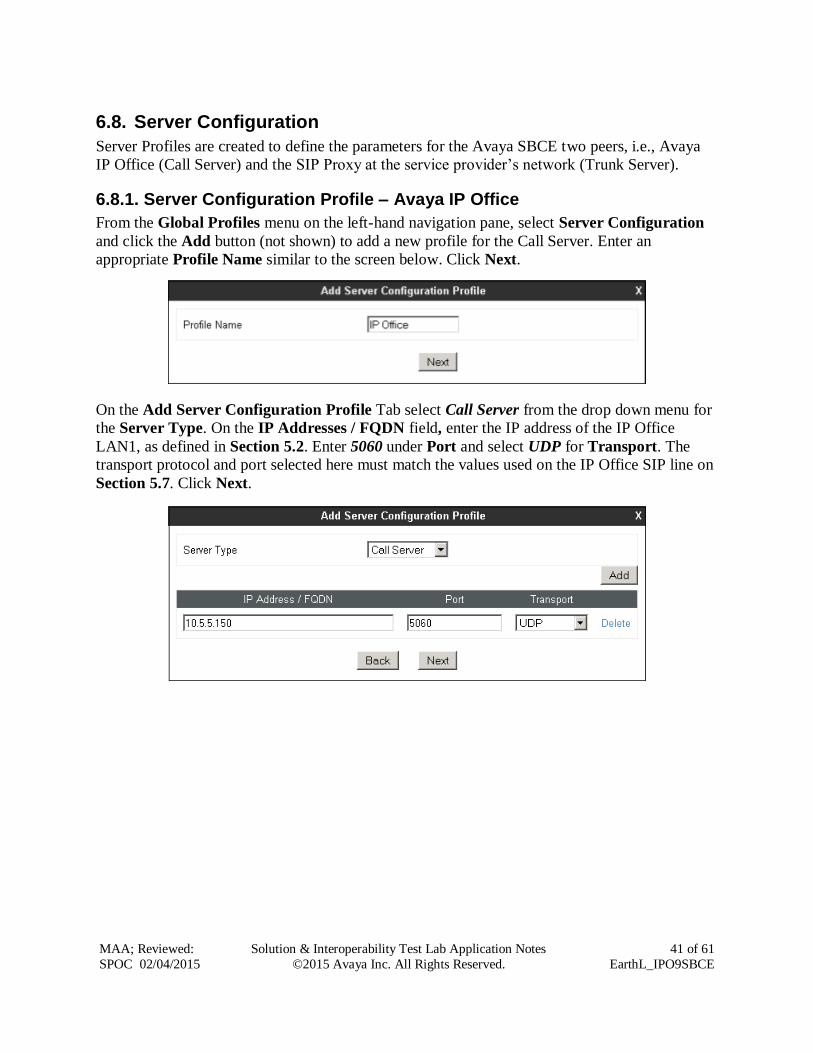
6.8.1. Server Configuration Profile – Avaya IP Office
From the Global Profiles menu on the left-hand navigation pane, select Server Configuration
and click the Add button (not shown) to add a new profile for the Call Server. Enter an
appropriate Profile Name similar to the screen below. Click Next.
On the Add Server Configuration Profile Tab select Call Server from the drop down menu for
the Server Type. On the IP Addresses / FQDN field, enter the IP address of the IP Office
LAN1, as defined in Section 5.2. Enter 5060 under Port and select UDP for Transport. The
transport protocol and port selected here must match the values used on the IP Office SIP line on
Section 5.7. Click Next.
Page 42
MAA; Reviewed:
SPOC 02/04/2015
Solution & Interoperability Test Lab Application Notes
©2015 Avaya Inc. All Rights Reserved.
42 of 61
EarthL_IPO9SBCE
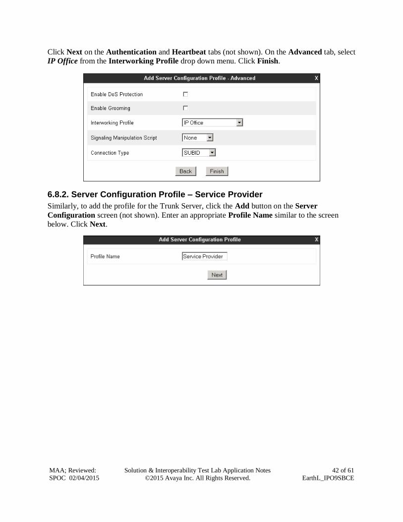
Click Next on the Authentication and Heartbeat tabs (not shown). On the Advanced tab, select
IP Office from the Interworking Profile drop down menu. Click Finish.
6.8.2. Server Configuration Profile – Service Provider
Similarly, to add the profile for the Trunk Server, click the Add button on the Server
Configuration screen (not shown). Enter an appropriate Profile Name similar to the screen
below. Click Next.
Page 43
MAA; Reviewed:
SPOC 02/04/2015
Solution & Interoperability Test Lab Application Notes
©2015 Avaya Inc. All Rights Reserved.
43 of 61
EarthL_IPO9SBCE
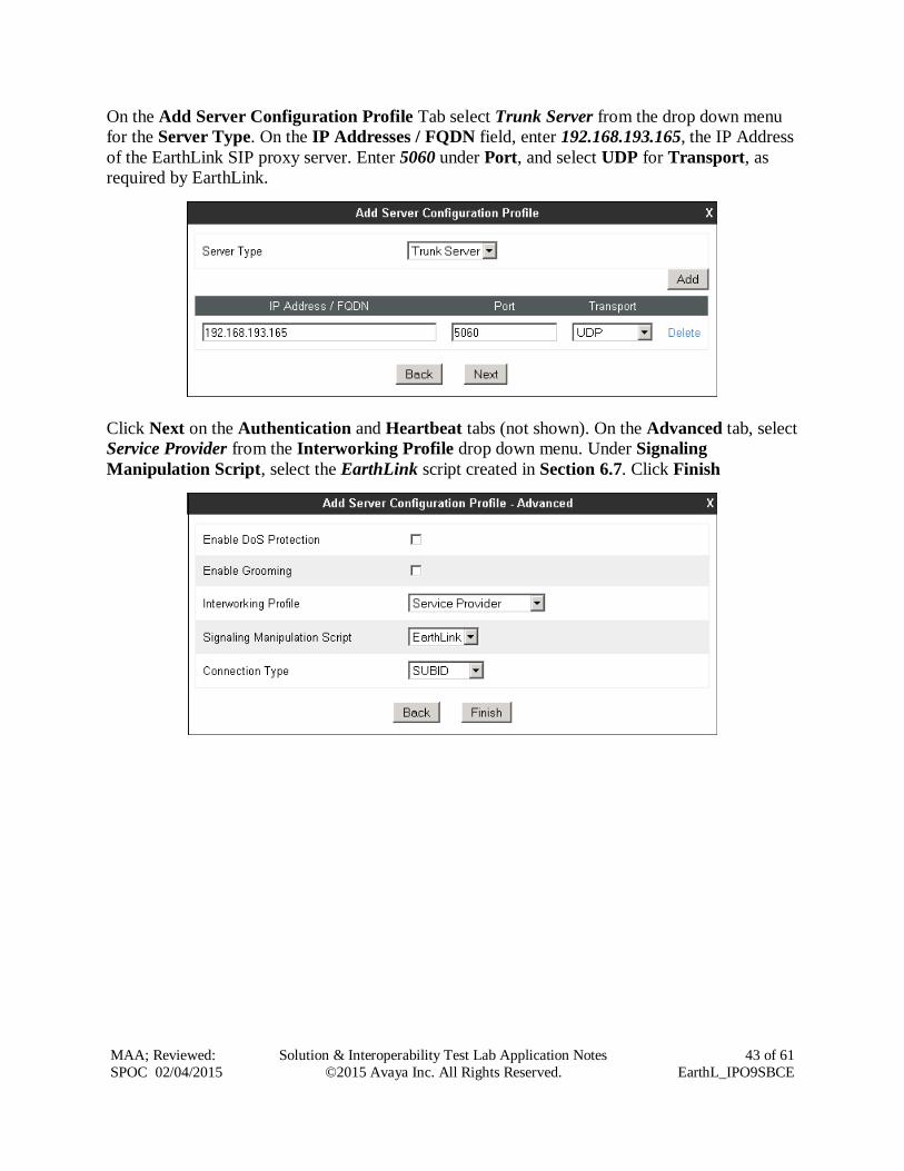
On the Add Server Configuration Profile Tab select Trunk Server from the drop down menu
for the Server Type. On the IP Addresses / FQDN field, enter 192.168.193.165, the IP Address
of the EarthLink SIP proxy server. Enter 5060 under Port, and select UDP for Transport, as
required by EarthLink.
Click Next on the Authentication and Heartbeat tabs (not shown). On the Advanced tab, select
Service Provider from the Interworking Profile drop down menu. Under Signaling
Manipulation Script, select the EarthLink script created in Section 6.7. Click Finish
Page 44
MAA; Reviewed:
SPOC 02/04/2015
Solution & Interoperability Test Lab Application Notes
©2015 Avaya Inc. All Rights Reserved.
44 of 61
EarthL_IPO9SBCE
6.9. Routing
Routing profiles define a specific set of routing criteria that is used, in addition to other types of
domain policies, to determine the path that the SIP traffic will follow as it flows through the
Avaya SBCE interfaces. Two Routing Profiles were created in the test configuration, one for
inbound calls, with the IP Office as the destination, and the second one for outbound calls, which
are routed to the EarthLink SIP trunk.
6.9.1. Routing Profile – Avaya IP Office
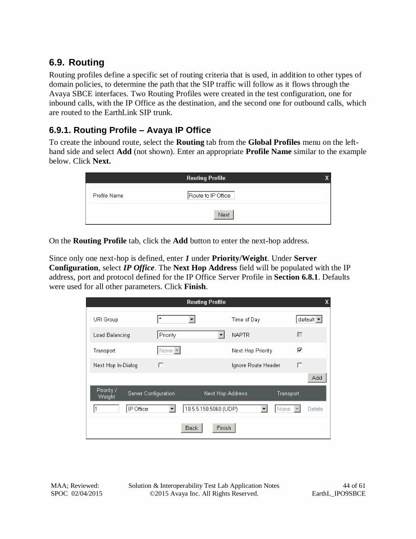
To create the inbound route, select the Routing tab from the Global Profiles menu on the left-
hand side and select Add (not shown). Enter an appropriate Profile Name similar to the example
below. Click Next.
On the Routing Profile tab, click the Add button to enter the next-hop address.
Since only one next-hop is defined, enter 1 under Priority/Weight. Under Server
Configuration, select IP Office. The Next Hop Address field will be populated with the IP
address, port and protocol defined for the IP Office Server Profile in Section 6.8.1. Defaults
were used for all other parameters. Click Finish.
Page 45
MAA; Reviewed:
SPOC 02/04/2015
Solution & Interoperability Test Lab Application Notes
©2015 Avaya Inc. All Rights Reserved.
45 of 61
EarthL_IPO9SBCE
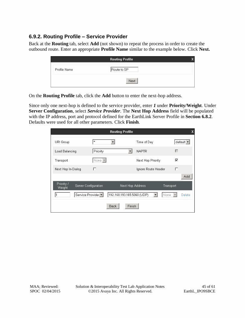
6.9.2. Routing Profile – Service Provider
Back at the Routing tab, select Add (not shown) to repeat the process in order to create the
outbound route. Enter an appropriate Profile Name similar to the example below. Click Next.
On the Routing Profile tab, click the Add button to enter the next-hop address.
Since only one next-hop is defined to the service provider, enter 1 under Priority/Weight. Under
Server Configuration, select Service Provider. The Next Hop Address field will be populated
with the IP address, port and protocol defined for the EarthLink Server Profile in Section 6.8.2.
Defaults were used for all other parameters. Click Finish.
Page 46
MAA; Reviewed:
SPOC 02/04/2015
Solution & Interoperability Test Lab Application Notes
©2015 Avaya Inc. All Rights Reserved.
46 of 61
EarthL_IPO9SBCE
6.10. Topology Hiding
Topology Hiding is a security feature that allows the modification of several SIP headers,
preventing private enterprise network information from being propagated to the untrusted public
network.
Topology Hiding can also be used as an interoperability tool to adapt the host portion in the SIP
headers to the IP addresses or domains expected on the service provider and the enterprise
networks. For the compliance test, only the minimum configuration required to achieve
interoperability on the SIP trunk was performed. Additional steps can be taken in this section to
further mask the information that is sent from the enterprise to the public network.
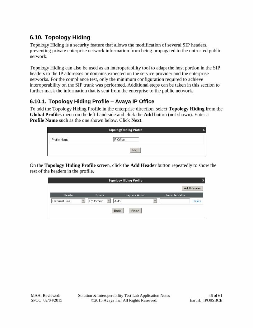
6.10.1. Topology Hiding Profile – Avaya IP Office
To add the Topology Hiding Profile in the enterprise direction, select Topology Hiding from the
Global Profiles menu on the left-hand side and click the Add button (not shown). Enter a
Profile Name such as the one shown below. Click Next.
On the Topology Hiding Profile screen, click the Add Header button repeatedly to show the
rest of the headers in the profile.
Page 47
MAA; Reviewed:
SPOC 02/04/2015
Solution & Interoperability Test Lab Application Notes
©2015 Avaya Inc. All Rights Reserved.
47 of 61
EarthL_IPO9SBCE
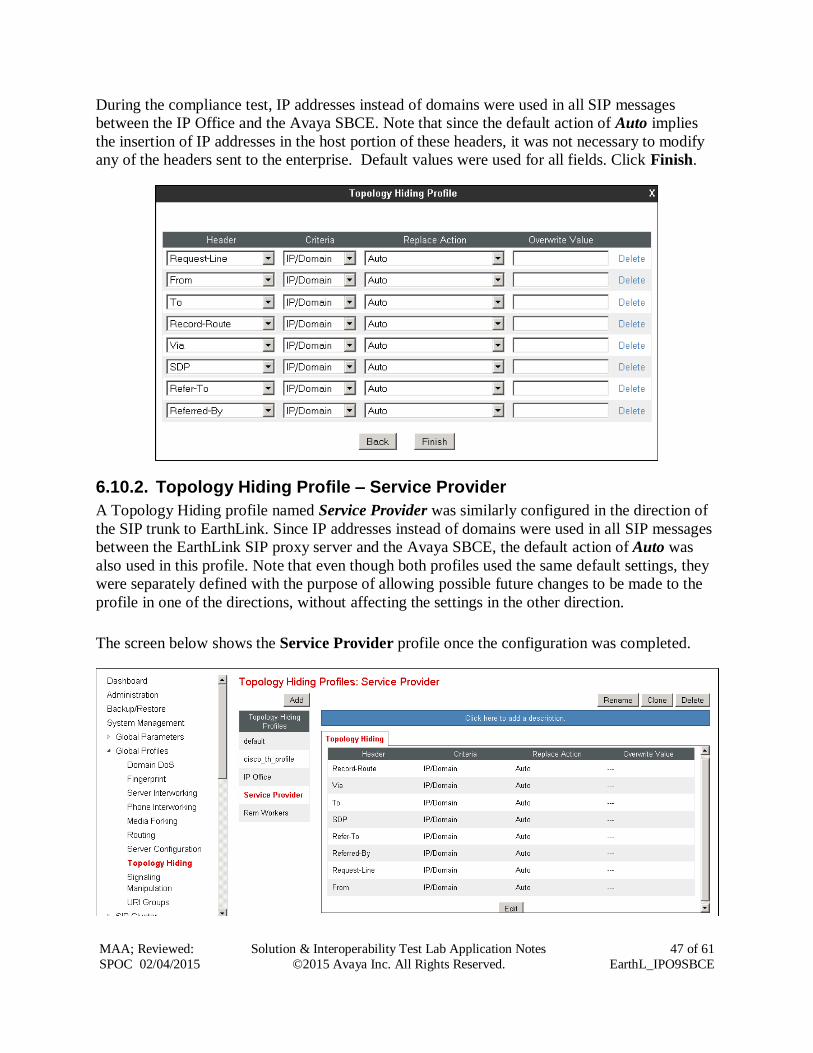
During the compliance test, IP addresses instead of domains were used in all SIP messages
between the IP Office and the Avaya SBCE. Note that since the default action of Auto implies
the insertion of IP addresses in the host portion of these headers, it was not necessary to modify
any of the headers sent to the enterprise. Default values were used for all fields. Click Finish.
6.10.2. Topology Hiding Profile – Service Provider
A Topology Hiding profile named Service Provider was similarly configured in the direction of
the SIP trunk to EarthLink. Since IP addresses instead of domains were used in all SIP messages
between the EarthLink SIP proxy server and the Avaya SBCE, the default action of Auto was
also used in this profile. Note that even though both profiles used the same default settings, they
were separately defined with the purpose of allowing possible future changes to be made to the
profile in one of the directions, without affecting the settings in the other direction.
The screen below shows the Service Provider profile once the configuration was completed.
Page 48
MAA; Reviewed:
SPOC 02/04/2015
Solution & Interoperability Test Lab Application Notes
©2015 Avaya Inc. All Rights Reserved.
48 of 61
EarthL_IPO9SBCE
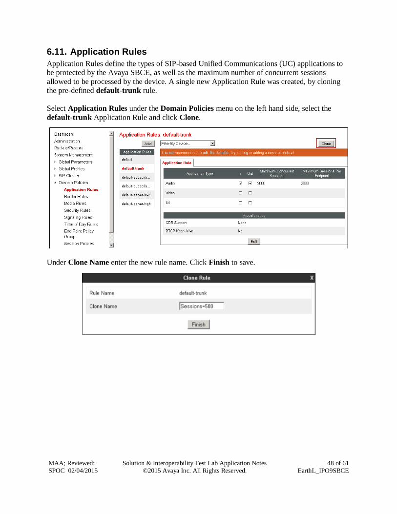
6.11. Application Rules
Application Rules define the types of SIP-based Unified Communications (UC) applications to
be protected by the Avaya SBCE, as well as the maximum number of concurrent sessions
allowed to be processed by the device. A single new Application Rule was created, by cloning
the pre-defined default-trunk rule.
Select Application Rules under the Domain Policies menu on the left hand side, select the
default-trunk Application Rule and click Clone.
Under Clone Name enter the new rule name. Click Finish to save.
Page 49
MAA; Reviewed:
SPOC 02/04/2015
Solution & Interoperability Test Lab Application Notes
©2015 Avaya Inc. All Rights Reserved.
49 of 61
EarthL_IPO9SBCE
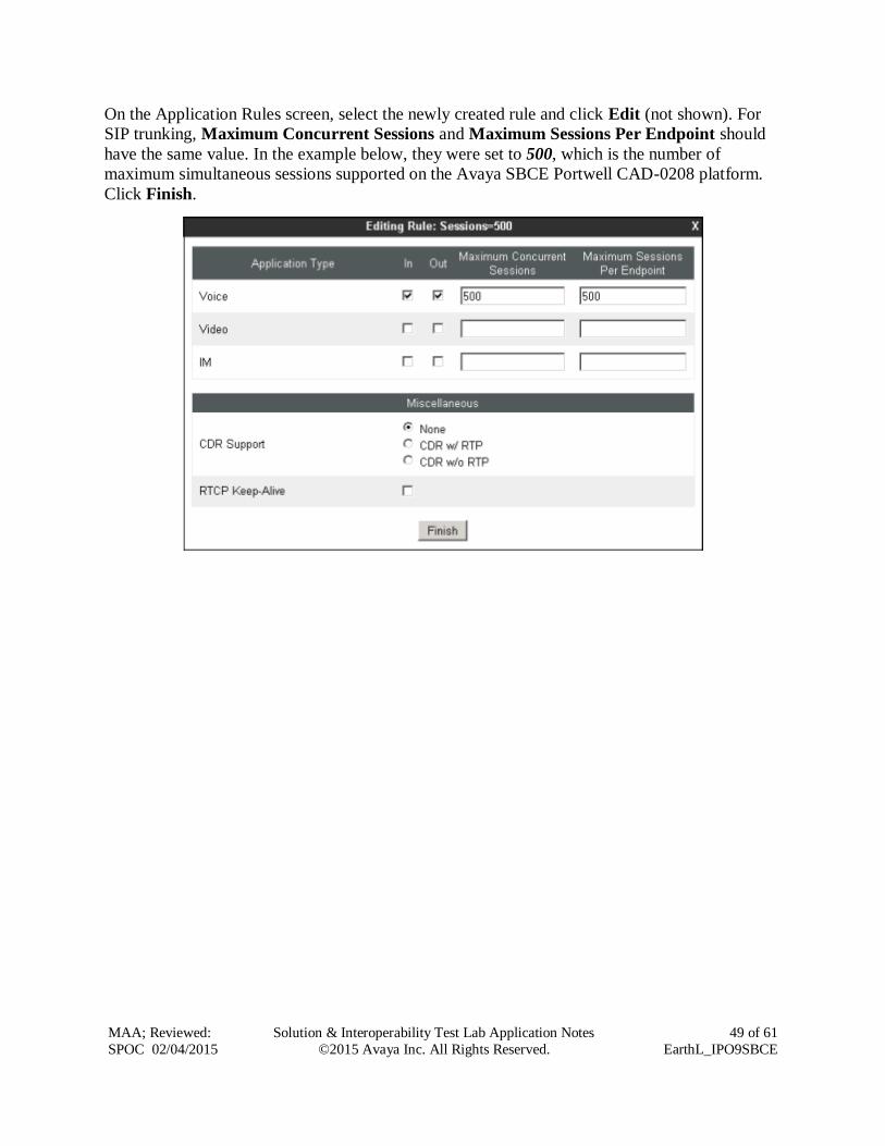
On the Application Rules screen, select the newly created rule and click Edit (not shown). For
SIP trunking, Maximum Concurrent Sessions and Maximum Sessions Per Endpoint should
have the same value. In the example below, they were set to 500, which is the number of
maximum simultaneous sessions supported on the Avaya SBCE Portwell CAD-0208 platform.
Click Finish.
Page 50
MAA; Reviewed:
SPOC 02/04/2015
Solution & Interoperability Test Lab Application Notes
©2015 Avaya Inc. All Rights Reserved.
50 of 61
EarthL_IPO9SBCE
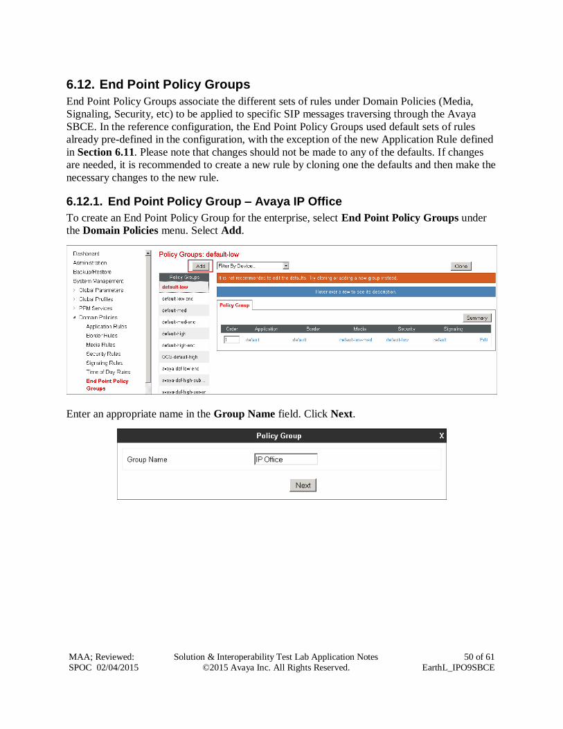
6.12. End Point Policy Groups
End Point Policy Groups associate the different sets of rules under Domain Policies (Media,
Signaling, Security, etc) to be applied to specific SIP messages traversing through the Avaya
SBCE. In the reference configuration, the End Point Policy Groups used default sets of rules
already pre-defined in the configuration, with the exception of the new Application Rule defined
in Section 6.11. Please note that changes should not be made to any of the defaults. If changes
are needed, it is recommended to create a new rule by cloning one the defaults and then make the
necessary changes to the new rule.
6.12.1. End Point Policy Group – Avaya IP Office
To create an End Point Policy Group for the enterprise, select End Point Policy Groups under
the Domain Policies menu. Select Add.
Enter an appropriate name in the Group Name field. Click Next.
Page 51
MAA; Reviewed:
SPOC 02/04/2015
Solution & Interoperability Test Lab Application Notes
©2015 Avaya Inc. All Rights Reserved.
51 of 61
EarthL_IPO9SBCE
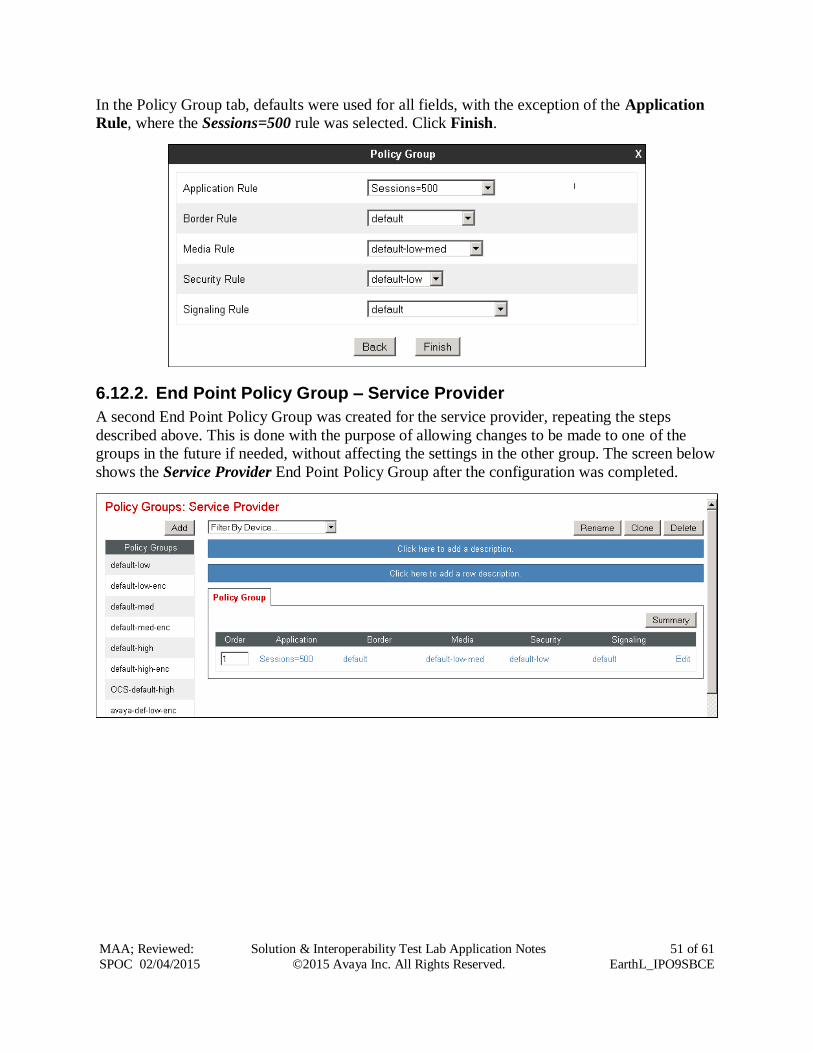
In the Policy Group tab, defaults were used for all fields, with the exception of the Application
Rule, where the Sessions=500 rule was selected. Click Finish.
6.12.2. End Point Policy Group – Service Provider
A second End Point Policy Group was created for the service provider, repeating the steps
described above. This is done with the purpose of allowing changes to be made to one of the
groups in the future if needed, without affecting the settings in the other group. The screen below
shows the Service Provider End Point Policy Group after the configuration was completed.
Page 52
MAA; Reviewed:
SPOC 02/04/2015
Solution & Interoperability Test Lab Application Notes
©2015 Avaya Inc. All Rights Reserved.
52 of 61
EarthL_IPO9SBCE
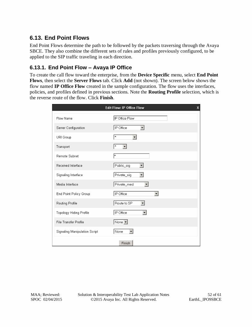
6.13. End Point Flows
End Point Flows determine the path to be followed by the packets traversing through the Avaya
SBCE. They also combine the different sets of rules and profiles previously configured, to be
applied to the SIP traffic traveling in each direction.
6.13.1. End Point Flow – Avaya IP Office
To create the call flow toward the enterprise, from the Device Specific menu, select End Point
Flows, then select the Server Flows tab. Click Add (not shown). The screen below shows the
flow named IP Office Flow created in the sample configuration. The flow uses the interfaces,
policies, and profiles defined in previous sections. Note the Routing Profile selection, which is
the reverse route of the flow. Click Finish.
Page 53
MAA; Reviewed:
SPOC 02/04/2015
Solution & Interoperability Test Lab Application Notes
©2015 Avaya Inc. All Rights Reserved.
53 of 61
EarthL_IPO9SBCE
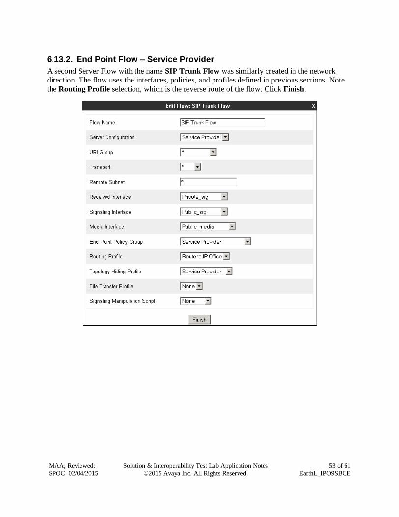
6.13.2. End Point Flow – Service Provider
A second Server Flow with the name SIP Trunk Flow was similarly created in the network
direction. The flow uses the interfaces, policies, and profiles defined in previous sections. Note
the Routing Profile selection, which is the reverse route of the flow. Click Finish.
Page 54
MAA; Reviewed:
SPOC 02/04/2015
Solution & Interoperability Test Lab Application Notes
©2015 Avaya Inc. All Rights Reserved.
54 of 61
EarthL_IPO9SBCE
7. EarthLink SIP Trunking Configuration EarthLink is responsible for the configuration of the EarthLink SIP Trunking service in its
network. The customer will need to provide the IP address used to reach the Avaya SBCE at the
enterprise. EarthLink will provide the customer the necessary information to configure the SIP
trunk connection from the enterprise site to the network, including:
IP address, protocol and port used to reach the EarthLink SIP Proxy server.
Supported codecs and order of preference.
DID numbers.
All IP addresses and port numbers used for signaling or media that will need access to the
enterprise network through any security devices.
8. Verification Steps The following sections include steps that may be used to verify the configuration of the Avaya IP
Office and the Avaya SBCE with the EarthLink SIP Trunking service.
8.1. Avaya IP Office
The Avaya IP Office System Status and Monitor applications are useful tools used for the
verification and troubleshooting of the SIP connection to the service provider via the Avaya
SBCE.
8.1.1. System Status
The Avaya IP Office System Status application can be used to verify the service state of the SIP
line. Launch the application from Start Programs IP Office System Status on the PC
where Avaya IP Office Manager was installed. Under Control Unit IP Address select the IP
address of the IP Office system under verification. Log in using the appropriate credentials
Page 55
MAA; Reviewed:
SPOC 02/04/2015
Solution & Interoperability Test Lab Application Notes
©2015 Avaya Inc. All Rights Reserved.
55 of 61
EarthL_IPO9SBCE
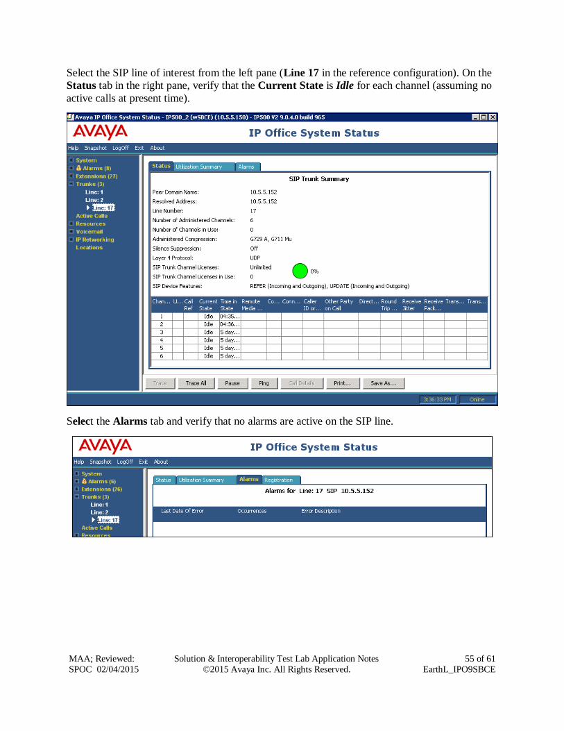
Select the SIP line of interest from the left pane (Line 17 in the reference configuration). On the
Status tab in the right pane, verify that the Current State is Idle for each channel (assuming no
active calls at present time).
Select the Alarms tab and verify that no alarms are active on the SIP line.
Page 56
MAA; Reviewed:
SPOC 02/04/2015
Solution & Interoperability Test Lab Application Notes
©2015 Avaya Inc. All Rights Reserved.
56 of 61
EarthL_IPO9SBCE
8.1.2. Monitor
The Avaya IP Office Monitor application can be used to monitor and troubleshoot signaling
messaging on the SIP trunk. Launch the application from Start Programs IP Office
Monitor on the PC where Avaya IP Office Manager was installed. Click the Select Unit icon on
the taskbar and Select the IP address of the IP Office system under verification.
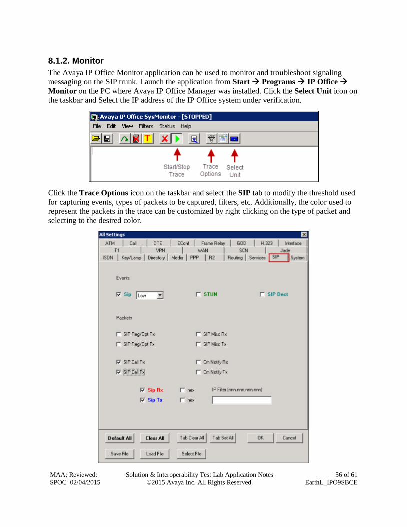
Click the Trace Options icon on the taskbar and select the SIP tab to modify the threshold used
for capturing events, types of packets to be captured, filters, etc. Additionally, the color used to
represent the packets in the trace can be customized by right clicking on the type of packet and
selecting to the desired color.
Page 57
MAA; Reviewed:
SPOC 02/04/2015
Solution & Interoperability Test Lab Application Notes
©2015 Avaya Inc. All Rights Reserved.
57 of 61
EarthL_IPO9SBCE
8.2. Avaya Session Border Controller for Enterprise
There are several links and menus located on the taskbar at the top of the screen of the web
interface that can provide useful diagnostic or troubleshooting information.
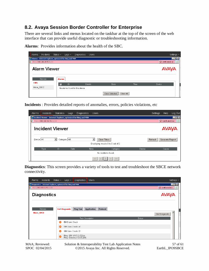
Alarms: Provides information about the health of the SBC.
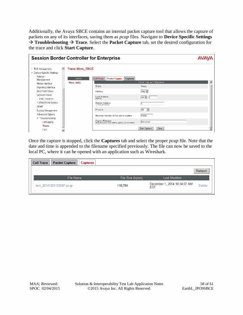
Incidents : Provides detailed reports of anomalies, errors, policies violations, etc
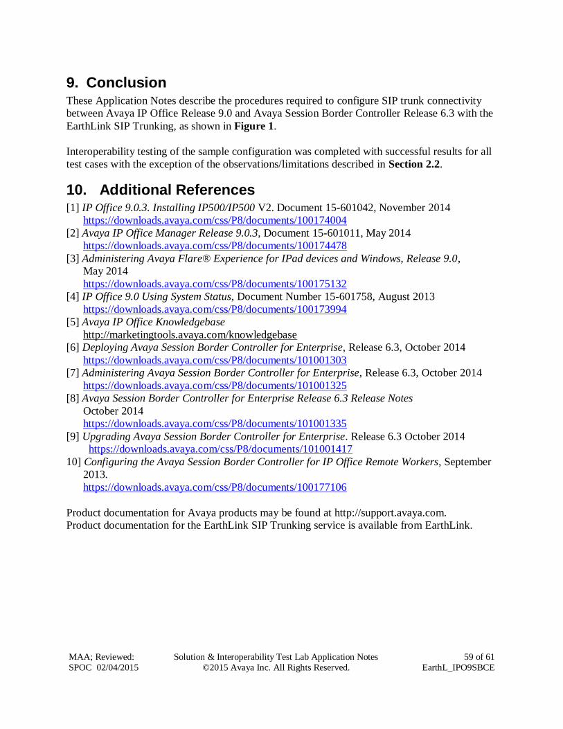
Diagnostics: This screen provides a variety of tools to test and troubleshoot the SBCE network
connectivity.
Page 58
MAA; Reviewed:
SPOC 02/04/2015
Solution & Interoperability Test Lab Application Notes
©2015 Avaya Inc. All Rights Reserved.
58 of 61
EarthL_IPO9SBCE
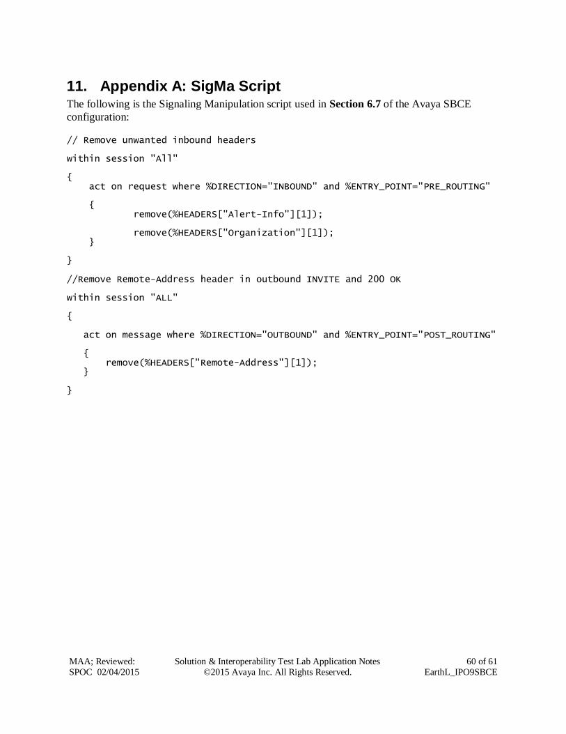
Additionally, the Avaya SBCE contains an internal packet capture tool that allows the capture of
packets on any of its interfaces, saving them as pcap files. Navigate to Device Specific Settings
Troubleshooting Trace. Select the Packet Capture tab, set the desired configuration for
the trace and click Start Capture.
Once the capture is stopped, click the Captures tab and select the proper pcap file. Note that the
date and time is appended to the filename specified previously. The file can now be saved to the
local PC, where it can be opened with an application such as Wireshark.
Page 59
MAA; Reviewed:
SPOC 02/04/2015
Solution & Interoperability Test Lab Application Notes
©2015 Avaya Inc. All Rights Reserved.
59 of 61
EarthL_IPO9SBCE
9. Conclusion These Application Notes describe the procedures required to configure SIP trunk connectivity
between Avaya IP Office Release 9.0 and Avaya Session Border Controller Release 6.3 with the
EarthLink SIP Trunking, as shown in Figure 1.
Interoperability testing of the sample configuration was completed with successful results for all
test cases with the exception of the observations/limitations described in Section 2.2.
10. Additional References [1] IP Office 9.0.3. Installing IP500/IP500 V2. Document 15-601042, November 2014
https://downloads.avaya.com/css/P8/documents/100174004
[2] Avaya IP Office Manager Release 9.0.3, Document 15-601011, May 2014
https://downloads.avaya.com/css/P8/documents/100174478
[3] Administering Avaya Flare® Experience for IPad devices and Windows, Release 9.0,
May 2014
https://downloads.avaya.com/css/P8/documents/100175132
[4] IP Office 9.0 Using System Status, Document Number 15-601758, August 2013
https://downloads.avaya.com/css/P8/documents/100173994
[5] Avaya IP Office Knowledgebase
http://marketingtools.avaya.com/knowledgebase
[6] Deploying Avaya Session Border Controller for Enterprise, Release 6.3, October 2014
https://downloads.avaya.com/css/P8/documents/101001303
[7] Administering Avaya Session Border Controller for Enterprise, Release 6.3, October 2014
https://downloads.avaya.com/css/P8/documents/101001325
[8] Avaya Session Border Controller for Enterprise Release 6.3 Release Notes
October 2014
https://downloads.avaya.com/css/P8/documents/101001335
[9] Upgrading Avaya Session Border Controller for Enterprise. Release 6.3 October 2014
https://downloads.avaya.com/css/P8/documents/101001417
10] Configuring the Avaya Session Border Controller for IP Office Remote Workers, September
2013.
https://downloads.avaya.com/css/P8/documents/100177106
Product documentation for Avaya products may be found at http://support.avaya.com.
Product documentation for the EarthLink SIP Trunking service is available from EarthLink.
Page 60
MAA; Reviewed:
SPOC 02/04/2015
Solution & Interoperability Test Lab Application Notes
©2015 Avaya Inc. All Rights Reserved.
60 of 61
EarthL_IPO9SBCE
11. Appendix A: SigMa Script The following is the Signaling Manipulation script used in Section 6.7 of the Avaya SBCE
configuration:
// Remove unwanted inbound headers within session "All" { act on request where %DIRECTION="INBOUND" and %ENTRY_POINT="PRE_ROUTING" { remove(%HEADERS["Alert-Info"][1]); remove(%HEADERS["Organization"][1]); } } //Remove Remote-Address header in outbound INVITE and 200 OK within session "ALL" { act on message where %DIRECTION="OUTBOUND" and %ENTRY_POINT="POST_ROUTING" { remove(%HEADERS["Remote-Address"][1]); } }
Page 61
MAA; Reviewed:
SPOC 02/04/2015
Solution & Interoperability Test Lab Application Notes
©2015 Avaya Inc. All Rights Reserved.
61 of 61
EarthL_IPO9SBCE
©2015 Avaya Inc. All Rights Reserved.
Avaya and the Avaya Logo are trademarks of Avaya Inc. All trademarks identified by ® and
™ are registered trademarks or trademarks, respectively, of Avaya Inc. All other trademarks
are the property of their respective owners. The information provided in these Application
Notes is subject to change without notice. The configurations, technical data, and
recommendations provided in these Application Notes are believed to be accurate and
dependable, but are presented without express or implied warranty. Users are responsible for
their application of any products specified in these Application Notes.
Please e-mail any questions or comments pertaining to these Application Notes along with the
full title name and filename, located in the lower right corner, directly to the Avaya
DevConnect Program at [email protected] .