Produced Water – Best Management Practices 28 & 29 November 2007 1 Application of an Enhanced Produced Water De-Oiling Technology to Middle East Oilfields M.J. Plebon, TORR Canada Inc. & Marc A. Saad, TORR Canada Inc. Nasser Jeham Al-Kuwari, Manager Production - Dukhan Fields, Qatar Petroleum Ahmed Abbad Al-Aji, Manager Production - Offshore Fields, Qatar Petroleum 1 ABSTRACT For maturing oil wells, the increasing production of water poses a serious challenge to upstream operators. Current disposal practices in the Middle East such as reinjection into disposal wells are presenting environmental concerns due to the long term accumulation of oil in the disposal wells. This oil accumulated over time in conjunction with the large volumes of produced water can contaminate neighboring water aquifers utilized for domestic requirements. The increasing volumes of produced water have deteriorated the characteristics of the oil in the water, consequently making the de-oiling process a more complicated challenge. Oil-in- water droplet size distribution, crude oil specifications, overall process equipment and chemical additives are often some of the major characteristics that need to be collectively addressed. Recently, seasonal changes in ambient conditions have proven to be a challenge for conventional de-oiling equipment. Qatar Petroleum (QP) has been looking at different technologies to address these challenges and have, over the years, performed a number of field trials using different technologies. This paper will present the results of the field trials performed at both the QP Dukhan (Onshore) Field and PS3 Bul Hanine (Offshore) Field using the TORR Canada Inc Technology. TORR Canada Inc. (The Company) has been applying its unique technology called TORR™ (Total Oil Remediation and Recovery) (The Technology) to de-oil produced water to meet and exceed disposal requirements and regulations. The presented solution has been designed to adapt to a wide range of field challenges including seasonal changes in ambient temperature. Both success and failure aspects of different trials are presented to demonstrate the directions taken to adapt a solution. The application of this technology in protecting water resources and solving production issues will be discussed. 2 INTRODUCTION As oil fields mature, the production of water can significantly increase. The industry perceives this excess produced water as a necessary evil that is often a liability and major cost centre. Offshore platforms are faced with additional challenges. The regulations for oil concentration in produced water discharged overboard commonly vary from 29 to 40 ppm. As the water cut increases, the retention time of existing primary separation equipment is reduced to cope with the excess produced water. Failure to handle the water quickly results in the water treatment becoming the bottleneck of the facility. Reduced retention time in the separation equipment can result in difficulties de-oiling the produced water to within discharge regulations. The State of Qatar’s Supreme Council for the Environment and Natural Reserves (SCENR) has mandated all oil production facilities in the state, including QP, to treat their produced water to attain the current maximum oil-in-water concentration limit of 40 ppm while maintaining an average of 20 ppm. QP has identified two producing fields where the need to polish the produced water to values lower than 20 ppm is required:
Transcript
Produced Water – Best Management Practices 28 & 29 November 2007
1
Application of an Enhanced Produced Water De-Oiling Technology to Middle East Oilfields
M.J. Plebon, TORR Canada Inc. & Marc A. Saad, TORR Canada Inc.
Nasser Jeham Al-Kuwari, Manager Production - Dukhan Fields, Qatar Petroleum Ahmed Abbad Al-Aji, Manager Production - Offshore Fields, Qatar Petroleum 1 ABSTRACT
For maturing oil wells, the increasing production of water poses a serious challenge to upstream operators. Current disposal practices in the Middle East such as reinjection into disposal wells are presenting environmental concerns due to the long term accumulation of oil in the disposal wells. This oil accumulated over time in conjunction with the large volumes of produced water can contaminate neighboring water aquifers utilized for domestic requirements.
The increasing volumes of produced water have deteriorated the characteristics of the oil in the water, consequently making the de-oiling process a more complicated challenge. Oil-in-water droplet size distribution, crude oil specifications, overall process equipment and chemical additives are often some of the major characteristics that need to be collectively addressed. Recently, seasonal changes in ambient conditions have proven to be a challenge for conventional de-oiling equipment.
Qatar Petroleum (QP) has been looking at different technologies to address these challenges and have, over the years, performed a number of field trials using different technologies. This paper will present the results of the field trials performed at both the QP Dukhan (Onshore) Field and PS3 Bul Hanine (Offshore) Field using the TORR Canada Inc Technology.
TORR Canada Inc. (The Company) has been applying its unique technology called TORR™ (Total Oil Remediation and Recovery) (The Technology) to de-oil produced water to meet and exceed disposal requirements and regulations. The presented solution has been designed to adapt to a wide range of field challenges including seasonal changes in ambient temperature. Both success and failure aspects of different trials are presented to demonstrate the directions taken to adapt a solution. The application of this technology in protecting water resources and solving production issues will be discussed. 2 INTRODUCTION As oil fields mature, the production of water can significantly increase. The industry perceives this excess produced water as a necessary evil that is often a liability and major cost centre. Offshore platforms are faced with additional challenges. The regulations for oil concentration in produced water discharged overboard commonly vary from 29 to 40 ppm. As the water cut increases, the retention time of existing primary separation equipment is reduced to cope with the excess produced water. Failure to handle the water quickly results in the water treatment becoming the bottleneck of the facility. Reduced retention time in the separation equipment can result in difficulties de-oiling the produced water to within discharge regulations. The State of Qatar’s Supreme Council for the Environment and Natural Reserves (SCENR) has mandated all oil production facilities in the state, including QP, to treat their produced water to attain the current maximum oil-in-water concentration limit of 40 ppm while maintaining an average of 20 ppm. QP has identified two producing fields where the need to polish the produced water to values lower than 20 ppm is required:
Produced Water – Best Management Practices 28 & 29 November 2007
2
ηρρ 18/)(2owr gdv −=
2.1 - Dukhan Onshore Oilfields Dukhan is a big oil field extending over an area of approximately 80 km by 8 km. and encompasses four reservoirs - Khatiyah, Fahahil and Jaleha/Diyab, three of which are oil reservoirs, and the fourth contains non associated gas. Oil and gas are separated in four main degassing stations which are continuously manned namely Khatiyah North, Khatiyah Main, Khatiyah South, Fahahil Main and Jaleha. Unmanned satellite stations are Fahahil North and Fahahil South. The Diyab satellite station at the South end of the field has no process facilities and the total oil production is sent to Jaleha station for processing. Dukhan oil field has production facilities to produce up to 335,000 Barrels per Day (BPD). The produced water is re-injected into the disposal wells in a formation below water aquifers. The disposal volumes and oil-in-water concentration amounts, accumulated over the long years, are now posing a threat on oil seepage into and contamination of the above water aquifers. 2.2 - Bul Hanine Offshore Oilfields The Bul Hanine oilfields are produced through the Production Station 3 (PS-3) offshore production platform. PS-3 produces crude oil, associated gas, condensate and produced water. Oil and condensate are piped to Halul Island Terminal for storage and export, gas is primarily used to assist in lifting the oil from the reservoir and some gas is taken to Halul for fuel. Produced Water is re-injected in disposal wells with a significant concentration of oil-in-water. Alternate disposal methods of the produced water, such as overboard discharge, which are environmentally friendlier and operationally more adequate needed to be investigated. All oil producing facility has significantly different composition and characteristics of produced water. The smaller the oil droplets found in the water, the more difficult it is to remove them. These small droplets are formed from the sheering effect of fluids passing from a high pressure process to a lower pressure through valves and pumps. The mechanical sheering can create a high proportion of dispersed oil in water of 20 µm and less. Even under favourable conditions, these droplets will be difficult to remove. Often chemicals are added to help facilitate the de-oiling process however chemical addition can be inefficient due to the low retention time and inadequate mixing. Unexpected upset conditions in the overall process increase the difficulty of the task of treating the produced water. In this paper, the basic theory of oil/water separation will be reviewed, the technology’s principles for removing and recovering dispersed oil from produced water will be discussed and supporting data will be presented from trials conducted at facilities in Qatar. The paper will show that the technology merits special consideration for de-oiling produced water to meet existing and future discharge regulations. All field data is a result from short term testing of one to four weeks. 3 OIL/WATER SEPARATION THEORY The separation of oil from water and the design of oil/water separation equipment are governed by Stokes’ Law which states:
(1)
From Stokes’ Law, several parameters can be manipulated to augment the separation of oil from water. However, the single most effective parameter that helps facilitate the separation process is the diameter of the oil droplet. The manipulation of the oil droplet diameter will have the largest impact on the rise velocity. Other issues play an important role in the separation efficiency process.
Produced Water – Best Management Practices 28 & 29 November 2007
4
Fig. 4 – General Layout of the Technology
Fig. 5 – Cutaway of Coalescing Element
4 THE TECHNOLOGY – HOW IT WORKS 4.1 Technology Overview The technology is a multi-stage separation system having the capacity of multi-phase separation of large and small oil droplets (free-floating and dispersed) present in produced water. (See Fig. 4) This is done by means of an adsorbent media, the Reusable Petroleum Adsorbent (RPA®, the media). This material is a polymer-based, oleophilic, hydrophobic, non-toxic, media coalescing agent. [1] The technology’s separation process consists of routing the oily water to its inlet. The oily water passes through the first vessel containing continuous coalescing elements which contain the media and a recovery chamber. The media continuously adsorbs the dispersed oil, coalesces the smaller droplets and desorbs larger oil droplets. These droplets rise to the top of the vessel’s recovery chamber. The oil and remaining solution gas (if any) are retrieved for re-use. The effluent water from the technology is treated to the customer’s requirements then disposed of either overboard as in the case for offshore facilities or re-injected into disposal wells or for enhanced oil recovery. A second vessel stage is available if required. [2]
Although upstream oil and gas production and produced water characteristics can vary from one operation to the other, the technology has reached a stage where it is developed and tested to operate within the following parameters:
• Oil Densities: APIº 16 and above. • Fluid Temperature: up to 95 ºC • Inlet Oil concentrations up to 2000 mg/L • Oil droplet diameters down to 2 μm • Flow rates up to 120,000 BWPD with one vessel • Handles upset conditions • Flow turndown ratio 100:1
Depending on the characteristics of the produced water to be treated, the efficiency of the system can be enhanced by providing optimized solutions on a case-by-case basis. This implies optimizing the two basic principles behind the technology being oil coalescence and gravity separation. 4.2 Coalescing Element Overview The coalescing element contains the proprietary media manufactured by the company. The element’s dimensions are standard for all sized and models available. The element is approximately 20 inches high, 6 inches outside diameter and 2 inches inner core. The number of elements contained in one vessel increases to accommodate the vessel’s designed produced water flow rates.
Produced Water – Best Management Practices 28 & 29 November 2007
5
Fig. 6 – Adsorption Process
Fig. 7 - Coalescence
Fig. 8 - Desorbtion
Fig. 9 – Gravity Separation
Three variables within the element can be modified to provide efficient coalescing properties to suit the specific site conditions. Permeability can be altered by the choice and combination of several versions of the coalescing media. The size of the media’s granular structure can be changed to vary the porosity characteristics and finally the compressibility factor is governed by the density in which the media is packed into the element’s housing. While the standard manufactured element can be applied to most produced water processes, the permeability, porosity and compressibility factor can be influenced to provide a unique solution to applications with very unique oil droplet characteristics such as “low oil drop per volume” ratios, complex reverse emulsions and oil droplets coated with chemical surfactants. The following diagrams will assist in describing how the dispersed oily water is treated and how the coalescing elements address the unique oil droplet characteristics often found in upstream applications.
The hydrocarbon contaminated produced water is channeled through the inner core of the continuous coalescing element (CCE). The top of the inner core is capped to force the flow of the oily water through the element. The thermoset polymeric backbone material media is designed to provide a micro-rugged contact surface area that allows for the increase in frictional forces between the dispersed oil droplets and the media. This effect, accompanied by the interfacial tension forces between the oil and the media, break up stable oil droplets 2 microns and larger and adsorbs them on to the media. The media structure in the coalescing elements defines a non-linear migration path for the oil film in a radial outward direction. The media porosity and oil film migration path optimizes the impact probability of oil droplets. Therefore produced water with low oil drop counts per volume is funnelled into a confined area and impact probability is increased. Control of the above parameters varies the probability of impact of smaller oil droplet sizes. Flow velocity controls droplet impact, adsorption and coalescence rates of the media in the coalescing elements.
The elasticity of the media structure in the coalescer element, along with the flow distribution and increased flow velocity of the water through the element, creates an inertial force and pressure drop that allows for the release of large oil droplets through the outer perimeter of the element. The process of adsorption, coalescence and desorbtion repeats itself many times even when the element is fully saturated with oil. The continuous coalescing element cleans itself of the hydrocarbons through the desorbtion of the large oil globules which then possess a high rise velocity. These large oil globules are recovered in the gravity separation recovery system at the top of the vessel. This process of adsorption, coalescence, desorbtion and gravity separation enables the recovery of hydrocarbons on a continuous basis with minimum intervention.
Produced Water – Best Management Practices 28 & 29 November 2007
6
Fig 10. – Field Apparatus
5 FIELD RESULTS The company would like to thank and acknowledge Qatar Petroleum for their cooperation at the Dukhan Fields and on PS3 platform in the Bul Hanine Oilfield. The company would also like to individually acknowledge Mr. Nasser Jeham Al-Kuwari who is the Manager of Production for the Dukhan Fields and Mr. Ahmed Abbad Al-Aji who is the Manager of Production for Offshore Fields. 5.1 Field Apparatus
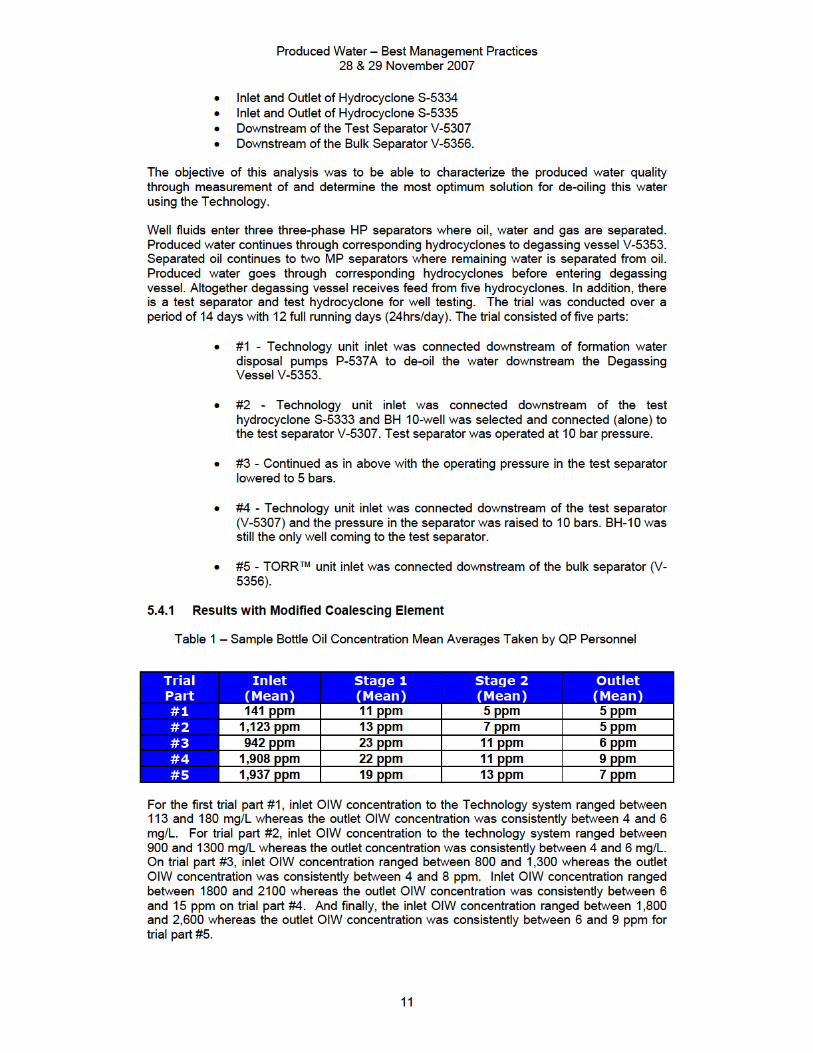
The field trial unit utilized for both Qatar Petroleum sites consisted of a three-stage 10 bar pressure rated system. Vessel body material is of stainless steel and each vessel incorporates a standard continuous coalescing element. The unit had a nominal flow rate capacity of 500 BWPD and maximum operating pressure and temperature of 10 bar and 95ºC respectively. A twin-set of bag filters (5 micron filters) was installed upstream of the Technology’s system to capture any solid particle upsets in the process fluid. Four sample points on the unit allowed for sampling at the inlet of the bag filters, inlet of the first, second and third stages.
5.2 Sampling and Analysis Sampling was done using 100 ml sample containers. Analysis was done with solvent extraction using Xylene as the solvent. Samples were measured using the Hach DR/4000u ultra-violet spectrum analyzer calibrated using crude oil produced from the wells feeding the facility. One measurement method used to evaluate the performance of the process is the Video Imaging Process Analyzer (ViPA). This combines a high-resolution video microscope with an image analysis system. It captures images of the particles in a process flow and allows the monitoring and analysis of those particles in real time. Information on the shape, size, optical density and fourteen other parameters are recorded for each particle in the image before the data is saved and the next image is captured. Up to eight particle types – or sub-populations – can be stored. Approximately fifteen images are analyzed each second. Oil in water emulsions - as all liquid in liquid emulsions - is characterized by their almost perfectly spherical shape. In sharp contrast, sand particles are crystalline and therefore very different in shape to the oil droplets. The analyzer can differentiate such geometries and organize them in a database. This measuring device can plot recorded parameters as an overall distribution for each or all sub-populations. The graphs are reported on screen and on the optional 4-20 mA output. The analyzer is also equipped with a comprehensive suite of trend analysis software. It determines the trends and trigger alarms. This provides vital time, especially on the field, before a process goes out of specifications, to take corrective action and prevent process upsets. [3] 5.3 Khatiyah South (KS) Degassing Station – Dukhan Oilfield, Qatar Petroleum The TORR de-oiler was trialed at the Khatiyah South (KS) degassing station at Qatar Petroleum’s (QP) onshore Dukhan oilfield to evaluate the performance of the system in de-oiling the produced water at that station downstream of the degasser. The produced water to be treated and currently discharged was downstream the degasser at KS and had the following characteristics:
Produced Water – Best Management Practices 28 & 29 November 2007
7
• No visible free-oil • Emulsified OIW • Very stable and small OIW emulsion with a mean size diameter of 4
microns • OIW concentration varying between 100 and 300 mg/L • Produced water temperature varying between 15 and 35 degrees Celsius • Produced water flow rates varying between 3,500 and 18,000 BWPD • Soluble oil content of 7 – 8 mg/L in the produced water
The objective of the trial was to meet the environmental oil-in-water (OIW) disposal limit of less than 40 mg/L with a target of 20 mg/L. Different models of full-scale coalescing elements were used to determine the most successful configuration in attaining the set OIW targets. Specially modified coalescer elements were designed for this extremely difficult application. The sampling and analysis of the results was done using standard QP methods and equipment and performed by QP personnel. Well fluids directed to the KS degassing station go from their respective manifolds into two parallel three-phase separators. The produced water discharged from the separators is then commingled and then passes through the common degasser 23-V-7280. From the degasser, gas is sent to the flare, oil is skimmed off and recovered and water is disposed of into disposal wells. The Technology field unit was fed from a 1” tie-in off the side of the main 16” degasser discharge line. The produced water was pumped through the Technology’s vessels and discharged 3 meters downstream of the feed tie-in. The Technology’s produced water feed and discharge tie-ins were upstream of the degasser level control valve. Recovered oil from the Technology’s vessels was evacuated manually into a collection apparatus. Produced water flow rates varied at the discharge of the degasser between 3,500 and 18,000 BWPD. Fluid flow through the Technology’s vessels was maintained at an average of 280 BWPD. Sock filters with a mesh size of 25 microns were installed upstream of the Technology to catch any coarse solids. However, no detectable solids were observed to be accumulated during the period of the trial. The process upstream of the Technology field unit had the following treatment chemicals being injected:
• Demulsifier at a rate of 35 ppm at the inlet of each three-phase separator. • Reverse Demulsifier at a rate of 3 ppm at the outlet of each three-phase
separator. The crude oil at Khatiyah South has the following characteristics:
• 35.9 API Gravity • Viscosity of 6.54 cSt @ 25 degrees Celsius
The produced water temperature measured varied between 15 and 35 degrees Celsius. 5.3.1 Results with Standard Coalescing Element The field trial was conducted between December 7th and December 12th with 12 hours running each day. The field unit utilized the Company’s standard coalescing element and only two of the three stages were used. Every day 3 to 5 samples were taken and measured in the production laboratory by Qatar Petroleum employees.
Produced Water – Best Management Practices 28 & 29 November 2007
9
Fig. 13 – Video Imaging Process Analyzer Results of Feed
Fig. 14 – Mean Oil Droplet Diameter of Feed
Fig. 15 – Visual Inlet/Outlet Samples with Modified
Element
Feed
Outlet
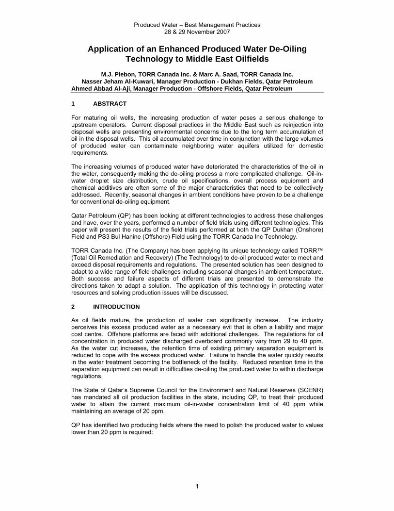
Figure 13 shows the result of a measured sample. The dark gray columns represent the percentage (y-axis) of oil droplets with different diameters in microns (x-axis) measured weighted by the total number of droplets measured. This is an indication of the count of droplets with their respective sizes. In the case of Figure 13, it shows that 3 micron sized
droplets constitute just less than 40% of the total droplets in the flow. Similarly 1 micron and 4 micron droplets are in the range of 15% each of the total droplets. The majority of the droplet count (dark grey columns) is less than 10 microns in size. The light grey columns represent the percentage of oil droplets with different diameters in microns measured weighted by the calculated
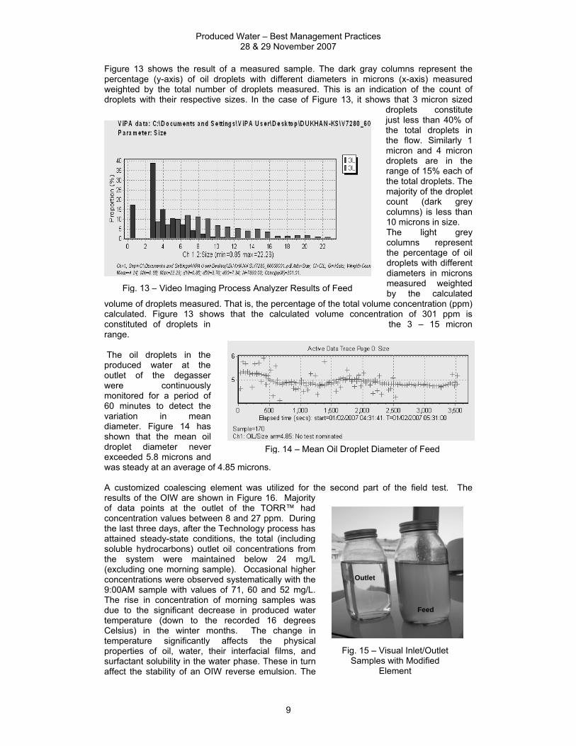
volume of droplets measured. That is, the percentage of the total volume concentration (ppm) calculated. Figure 13 shows that the calculated volume concentration of 301 ppm is constituted of droplets in the 3 – 15 micron range. The oil droplets in the produced water at the outlet of the degasser were continuously monitored for a period of 60 minutes to detect the variation in mean diameter. Figure 14 has shown that the mean oil droplet diameter never exceeded 5.8 microns and was steady at an average of 4.85 microns. A customized coalescing element was utilized for the second part of the field test. The results of the OIW are shown in Figure 16. Majority of data points at the outlet of the TORR™ had concentration values between 8 and 27 ppm. During the last three days, after the Technology process has attained steady-state conditions, the total (including soluble hydrocarbons) outlet oil concentrations from the system were maintained below 24 mg/L (excluding one morning sample). Occasional higher concentrations were observed systematically with the 9:00AM sample with values of 71, 60 and 52 mg/L. The rise in concentration of morning samples was due to the significant decrease in produced water temperature (down to the recorded 16 degrees Celsius) in the winter months. The change in temperature significantly affects the physical properties of oil, water, their interfacial films, and surfactant solubility in the water phase. These in turn affect the stability of an OIW reverse emulsion. The
Produced Water – Best Management Practices 28 & 29 November 2007
13
ρw the water density (kg/m3) ρo the oil density (kg/m3) η the water viscosity (kg/m,sec) 8 REFERENCES [1] RPA® Liquid Sorbent, Canada Patent 2,085,951. [2] TORR™ Patent Pending, Canada PCT/CA01/-1284, UK 0022013.7 [3] R. GASKIN. The ViPA, Jorin Limited, http://www.jorin.co.uk/vipa.htm.


![State of the Art Treatment of Produced Water · State of the Art Treatment of Produced Water 201 3. Produced water management[1] a. Injection into oil wells: The produced water is](https://static.documents.pub/doc/80x56/5e7f81b70c60f14f6a1c8785/state-of-the-art-treatment-of-produced-water-state-of-the-art-treatment-of-produced.jpg)
