VINCENT F. NERADKA, YALE CHANG, JOSEPH E. GRADY , and DANIEL A. TROWBRIDGE APPLICATION OF COMPOSITE MATERIALS TO IMPACT-INSENSITIVE MUNITIONS Over the years, catastrophic accidents have been caused by Navy shipboard munitions that detonated from unplanned stimuli. An international effort is under way to develop insensitive munitions-munitions that exhibit only mild reaction to the unplanned stimuli of fragment and bullet impact, fast and slow cook-off (thermal dwell), and sympathetic detonation. Achieving insensitive munitions for these stimuli requires a unique solution, and bullet impact-insensitivity has proved especially difficult to attain. This article describes a new approach to the development of bullet-impact-insensitive munitions by tailoring the composite material properties to provide rapid venting of the rocket motor case. Test results show that the failure mechanisms of a composite structure can indeed be tailored by material design variables and provide, for the first time, measured bullet impact data, which can be used for analytical predictions. INTRODUCTION "It could be argued that we have lo st more warfighting capabilities due to our own munition s than to hostile action ," re marked Rear Admiral Min g E. Chang in hi s keynote address (Joint Service Bri efin g to Indu stry on In se nsitive Munition s, Dec 1986) urging the rapid devel- opment of in se nsitive munition s. Shipboard munition s accidents s imilar to tho se caused by deto nation of a solid propellant (Fig. 1) have had serious consequences. Sinc e 1966, the se accidents have resulted in 220 death s and 702 injuries, and have damaged or de stroyed over 100 aircraft, causing mater ial losses es timated at $196 mil- lion (keynote address, M. E. Chang). Insensitive muni- tions will minimi ze the violence of reaction and collat- e ral damage that occur as the result of such accidents. Th e need to deve lop such munition s has motivated the recent efforts of APl, the U.S. Depa rtment of Defense , and NATO co untries. The U.S. introduction of in sensitive munition s into the fleet is scheduled for 1995.' The deve lopment of in se nsitive munition s ha s pre- sented considerable challenges in rece nt years. Meeting the requirem ent of bu ll et impact in se nsitivity has prov ed particularly difficult. For composite rocket motor cases, the objective is to des ign a motor case such that bullet impact doe s not cause detonation of the propellant. This article describes a new approach to the design of bullet- impact-insensitive munition s by tailoring the material properties of high-strength, li ght we ight composite ma- terials. The design causes extensive failure in response to bullet impact , thereby achieving rapid venting of the rocket motor case. But beca use of the dynamic natur e of this tailoring, the motor ca se would not be damaged by other lif e-cycle imp acts (e.g., s hipboard shock), and thus its st ructural integrity would be maintain ed. Th e term "dynamic tailorin g" was coined to desc ribe thi s process. To achieve ra pid venting, we first identified theoretical failure m ec hanisms likely to be caused by 418 Figure 1. Detonation of a solid propellant in a rocket motor case during a 50-cali ber bullet impact test at the Naval Air Warfare Center, China Lake, California. bullet impact. Th en seve ral composite configurations that would ex hibit these failure mechanisms were designed, fabricated, and bullet- impa cted. Result s show the extent j o lill s /-/ opkills APL Tec hllical Digest. Vo lume 13. Number 3 (/ 992)
Transcript
VINCENT F. NERADKA, YALE CHANG, JOSEPH E. GRADY, and DANIEL A. TROWBRIDGE
APPLICATION OF COMPOSITE MATERIALS TO IMPACT-INSENSITIVE MUNITIONS
Over the years, catastrophic accidents have been caused by Navy shipboard munitions that detonated from unplanned stimuli. An international effort is under way to develop insensitive munitions-munitions that exhibit only mild reaction to the unplanned stimuli of fragment and bullet impact, fast and slow cook-off (thermal dwell), and sympathetic detonation. Achieving insensitive munitions for these stimuli requires a unique solution, and bullet impact-insensitivity has proved especially difficult to attain. This article describes a new approach to the development of bullet-impact- insensitive munitions by tailoring the composite material properties to provide rapid venting of the rocket motor case. Test results show that the failure mechanisms of a composite structure can indeed be tailored by material design variables and provide, for the first time, measured bullet impact data, which can be used for analytical predictions.
INTRODUCTION
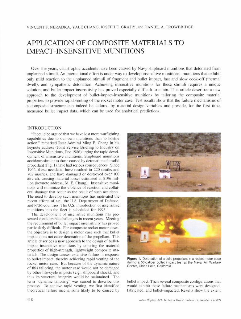
"It could be argued that we have lost more warfighting capabilities due to our own munitions than to hostile action ," remarked Rear Admiral Ming E. Chang in hi s keynote address (Joint Service Briefing to Industry on Insensitive Munitions, Dec 1986) urg ing the rapid deve lopment of insensitive munitions. Shipboard munitions acc idents similar to those caused by detonation of a solid propellant (Fig. 1) have had serious consequences. Since 1966, these accidents have resulted in 220 deaths and 702 injuries, and have damaged or destroyed over 100 a ircraft, causing material losses estimated at $ 196 million (keynote address, M. E. Chang) . Insensitive munitions will minimi ze the violence of reaction and collateral damage that occur as the result of such accidents. The need to develop such munitions has motivated the recent efforts of APl, the U.S. Department of Defense, and NATO co untries. The U.S. introduction of in sensitive munitions into the fleet is scheduled for 1995.'
The development of insensitive munitions has presented considerable challenges in recent years. Meeting the requirement of bu llet impact in sensitivity has proved particularly difficult. For composite rocket motor cases, the objective is to des ign a motor case such that bullet impact does not cause detonation of the propellant. This article describes a new approach to the des ign of bulletimpact-insensitive munitions by tailoring the material properties of high-strength , lightweight composite materials. The design causes ex tensive fa ilure in response to bullet impact, thereby achieving rapid venting of the rocket motor case. But because of the dynamic nature of this tailoring , the motor case would not be damaged by other life-cycle impacts (e.g. , shipboard shock), and thu s its structural integrity would be maintained. The term "dynamic tailoring" was coined to describe thi s process. To achieve rapid venting, we first identified theoretical failure mechanisms likely to be caused by
418
Figure 1. Detonation of a solid propellant in a rocket motor case during a 50-caliber bullet impact test at the Naval Air Warfare Center, China Lake, California.
bullet impact. Then several composite configurations that would ex hibit these failure mechanisms were designed , fabricated , and bullet- impacted. Results show the extent
j olills /-/opkills A PL Techllical Digest. Vo lume 13. Number 3 ( / 992)
to which the failure modes of a composite structure are determined by the material design variables .
COMPOSITE DESIGN FOR INSENSITIVE MUNITIONS ROCKET MOTORS
Through the interdisciplinary application of structures, composite materials, fracture mechanics, and computer technologies, it is now feasib le to design a structure insensitive to bullet impact. The Naval Air Warfare Center (NAWC) Weapons Division, China Lake (formerly the Naval Weapons Center) has established that the fracture of an impacted rocket motor case can prevent the burning propellant from detonating by the rapid venting of the high internal pressure away from the combustion chamber. 2 This phenomenon is ca lled the rapid venting fai lure mode. The process of initiating and controlling fracture has not yet been successfully applied to production configurations. It is, however, attainable through the dynamic tailoring of composite failure modes. Tailoring results in a unique design methodology, incorporating the insensitive munitions attribute without sacrificing existing design features.
The composite material is tailored to provide the same stiffness and strength as the motor cases currently in use, but it should also fracture rapidly and over a large area in response to bullet impact. The fai lure characteristics desired are analogous to those of tempered glass, which has high strength and stiffness, but fractures completely when impacted with enough force. This objective might be accomplished by using a carefully designed composite material that fails by one or more of the failure mechani sms discussed later in this article.
We conceived a program to design an insensitive munitions rocket motor through a systems integration of diverse technologies. The diversity of the activities needed to accomplish the program objectives also required the integration of several organizational activities, and these are noted throughout the article. The program plan called for an iterative approach of computer analysis, composite design, and bullet impact testing. Because of the complexity of the problem, initial efforts focused on making predictions for a free-free flat-plate composite specimen in response to bullet impact. The planned geometries progressed toward representation of the actual propellantfilled filament-wound rocket motor. Each iterative step was to conclude with a validation of the analys is by comparison with the test data. This incremental approach provides a foundation . for subsequent phases, wh ich become increasingly costly. Each step serves as a rational decision point for program continuation. Work has progressed just short of the first of these validation junctures-the comparison of the analytical results with the bullet impact tests.
Composite Failure Modes
Laminated composites have complex structures and material properties that make them distinct from other materials. As a result, they also exhibit unique fai lure modes. Composite materials fracture primarily by delaminating when the matrix material cracks and the plies debond from each other. Interlaminar fracture toughness
.loll/IS Hopkins APL Technical Digest. Vo illme 13. Number 3 (1992)
is the ability of a composite material to resist delamination, and this toughness can be used as a measure of the impact resistance of the material. The fracture toughness of polymer matrix composites is determined primarily by the properties of the matrix material. In general, an increase in the ductility of the matrix wi ll cause a corresponding increase in the fracture toughness of the composite.
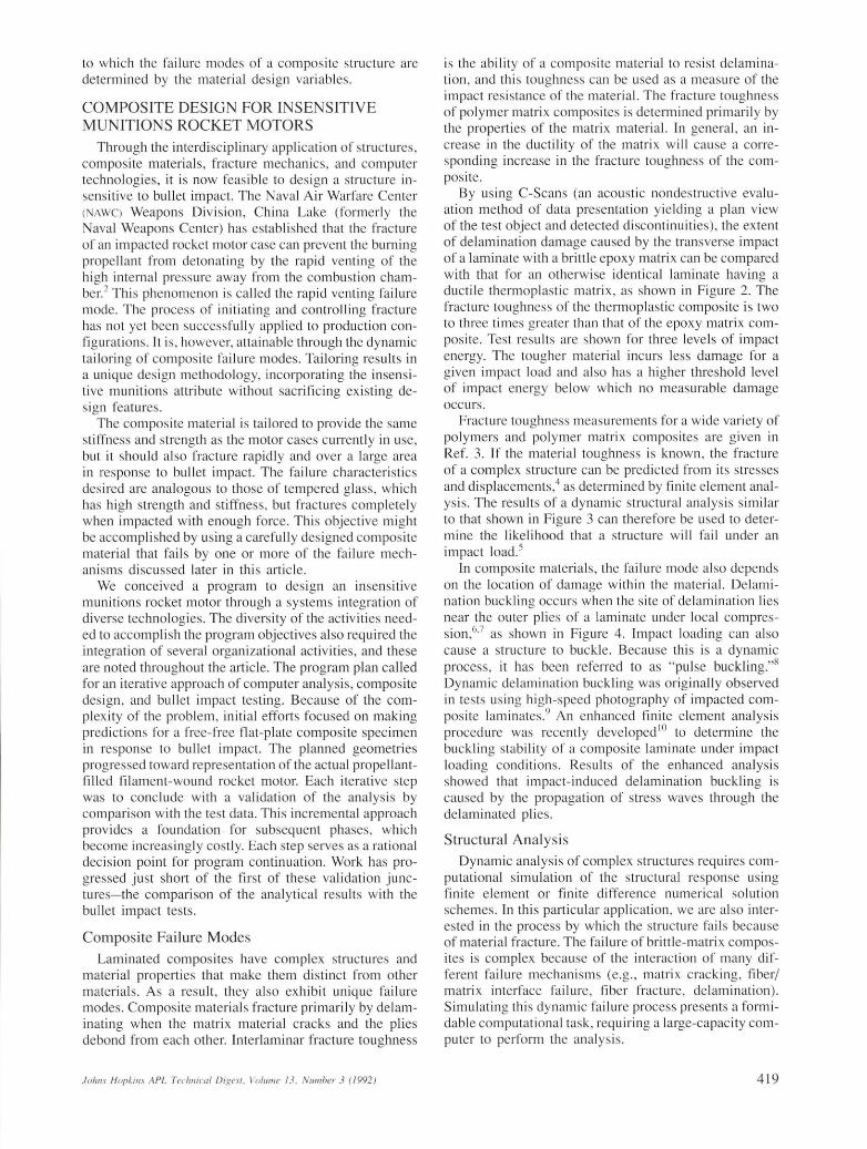
By using C-Scans (an acoust ic nondestructive evaluation method of data presentation yie lding a plan view of the test object and detected discontinuities), the extent of delamination damage caused by the transverse impact of a laminate with a brittle epoxy matrix can be compared with that for an otherwise identical laminate having a ductile thermoplastic matrix, as shown in Figure 2. The fracture toughness of the thermoplastic composite is two to three times greater than that of the epoxy matrix composite. Test results are shown for three levels of impact energy. The tougher material incurs less damage for a given impact load and also has a higher threshold level of impact energy below which no measurable damage occurs.
Fracture toughness measurements for a wide variety of polymers and polymer matrix composites are given in Ref. 3. If the material toughness is known, the fracture of a complex structure can be predicted from its stresses and displacements,4 as determined by finite element analysis . The results of a dynamic structural analysis similar to that shown in Figure 3 can therefore be used to determine the likel1hood that a structure will fail under an impact load.s
In composite materials, the failure mode also depends on the location of damage within the material. Delamination buckling occurs when the site of delamination lies near the outer plies of a laminate under local compression ,6.7 as shown in Figure 4. Impact loading can also cause a structure to buckle. Because this is a dynamic process, it has been referred to as "pulse buckling."g Dynamic delamination buckling was originally observed in tests using high-speed photography of impacted composite laminates. 9 An enhanced finite element analysis procedure was recently developed 10 to determine the buckling stability of a composite laminate under impact loading conditions . Results of the enhanced analysis showed that impact-induced delamination buckling is caused by the propagation of stress waves through the delaminated plies.
Structural Analysis
Dynamic analysis of complex structures requires computational simulation of the structural response using finite element or finite difference numerical solution schemes. In this particular application , we are also interested in the process by which the structure fails because of material fracture. The failure of brittle-matrix composites is complex because of the interaction of many different failure mechanisms (e.g., matrix cracking, fiber/ matrix inteIface failure , fiber fracture, delamination). Simulating this dynamic failu re process presents a formidable computational task, requiring a large-capacity computer to perform the analysis.
419
V. F. Neradka ef al .
A
Figure 2. Ultrasonic C-Scans show less delamination for a tougher thermoplastic matrix after impact . A. Impactinduced delamination in T300/934 B graphite/epoxy . B. Impact-induced delamination in AS4/PEEK graphite/ thermoplastic.
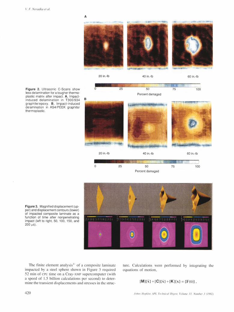
Figure 3. Magnified displacement (upper) and displacement contours (lower) of impacted composite laminate as a function of time after nonpenetrating impact (left to right, 50 , 100, 150, and 200 j-ts).
20 in.-Ib
o
20 in. -Ib
o
The finite e lement analysis!! of a composite laminate impacted by a steel sphere shown in Figure 3 required 52 min of CPU time on a CraY-XMP supercomputer (with a speed of 1.5 bi lli on calculations per second) to determine the transient displacements and stresses in the struc-
420
25
25
40 in .-Ib
50
Percent damaged
40 in.-Ib
50
Percent damaged
60 in.-Ib
100
60 in.-Ib
75 100
ture. Calcu lations were performed by integrating the equations of motion ,
Figure 4. Example of delamination buckli ng under local compression.
for the first 200 fJ-s after impact. The impact force vector {F(t)} and resulting displacement vector {x} are timedependent. In addition, the mass matrix [M], stiffness matrix [K], and damping matrix [C] may also change with time if damage develops in the material as a result of the impact load.
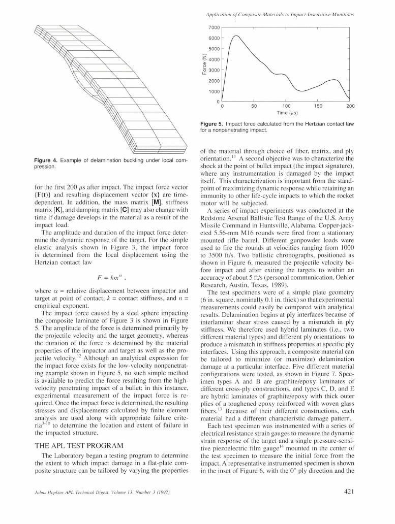
The amplitude and duration of the impact force determine the dynamic response of the target. For the simple elastic analysis shown in F igure 3, the impact force is determined from the local displacement using the Hertzian contact law
F = kot" ,
where ex = relative displacement between impactor and target at point of contact, k = contact stiffness, and n = empirical exponent.
The impact force caused by a steel sphere impacting the composite laminate of Figure 3 is shown in Figure 5. The amplitude of the force is determined primarily by the projectile velocity and the target geometry, whereas the duration of the force is determined by the material properties of the impactor and target as well as the projectile velocity. 12 Although an analytical expression for the impact force exists for the low-velocity nonpenetrating example shown in Figure 5, no such simple method is available to predict the force resulting from the highvelocity penetrating impact of a bullet; in th is instance, experimental measurement of the impact force is required. Once the impact force is determined, the resulting stresses and displacements calculated by fin ite element analysis are used along with appropriate failure criteria3
-10 to determine the location and extent of failure in
the impacted structure.
THE APL TEST PROGRAM The Laboratory began a testing program to determine
the extent to which impact damage in a flat-plate composite structure can be tailored by varying the properties
Application a/Composite Materials to Impact-Insensitive Munitions
7000 ,--------,--------.---------,--------,
6000
5000
2:.- 4000 CD
~ 3000 LL
2000
1000
o L-------~--------~--------L-------~
o 50 100 150 200 Time (J-t5)
Figure 5. Impact force calcu lated from the Hertzian contact law for a nonpenetrating impact.
of the material through choice of fiber, matrix, and ply orientation. !3 A second objective was to characterize the shock at the point of bullet impact (the impact signature), where any instrumentation is damaged by the impact itself. This characterization is important from the standpoint of maximizing dynamic response while retaining an immunity to other life-cycle impacts to which the rocket motor will be subjected.
A series of impact experiments was conducted at the Redstone Arsenal Ballistic Test Range of the U.S. Army Missile Command in Huntsville, Alabama. Copper-jacketed 5.56-mm M16 rounds were fired from a stationary mounted rifle barrel. Different gunpowder loads were used to fire the rounds at velocities ranging from 1000 to 3500 ft/s. Two ballistic chronographs, positioned as shown in Figure 6, measured the projectile velocity before impact and after exiting the targets to within an accuracy of about 5 ft/s (personal communication, Oehler Research , Austin , Texas , 1989).
The test specimens were of a simple plate geometry (6 in. square, nominally 0.1 in. thick) so that experimental measurements could easily be compared with analytical results. Delamination begins at ply interfaces because of interlaminar shear stress caused by a mismatch in ply stiffness. We therefore used hybrid laminates (i .e., two different material types) and different ply orientations to produce a mismatch in stiffness properties at specific ply interfaces. Using this approach, a composite material can be ta ilored to minimize (or maximize) delam ination damage at a particular interface. Five different material configurations were tested, as shown in Figure 7. Specimen types A and B are graphite/epoxy laminates of different cross-ply constructions, and types C, D, and E are hybrid laminates of graphite/epoxy with thick outer plies of a toughened epoxy reinforced with woven glass fibers. 13 Because of their different constructions, each material had a different characteristic damage pattern.
Each test specimen was instrumented with a series of electrical resistance strain gauges to measure the dynamic strain response of the target and a single pressure-sensitive piezoelectric film gauge l 4 mounted in the center of the test specimen to measure the initial force from the impact. A representative instrumented specimen is shown in the inset of Figure 6, with the 0° ply direction and the
421
V. F. Neradka et al.
Figure 6. Bal listic test range, showing chronographs, test specimen support, and test specimen (inset). Rifle barrel in foreground is not visible .
Figure 7. Cross sections of test specimen ply orientations for five layups, A th rough E (s ymmetr ic across the midplane). (Red , glass weave ; blue , 0° ply; gray, 90° ply.)
specimen type "E" clearly marked. The transient signal s fro m the gauges were digitally sampled at a rate of 18 MHz and recorded with a four-channel data acquisition system , which was triggered by a voltage spike generated when the bullet compressed the piezoelectric film gauge. A nonlinear data reduction scheme 1.'1 was used to account for the effects of large strain amplitudes in converting the recorded voltage outputs into strain readings . A compi-
422
lat ion of the strai n data from each test is g iven In
Ref. 13.
RESULTS The impac t force is determined by integration of the
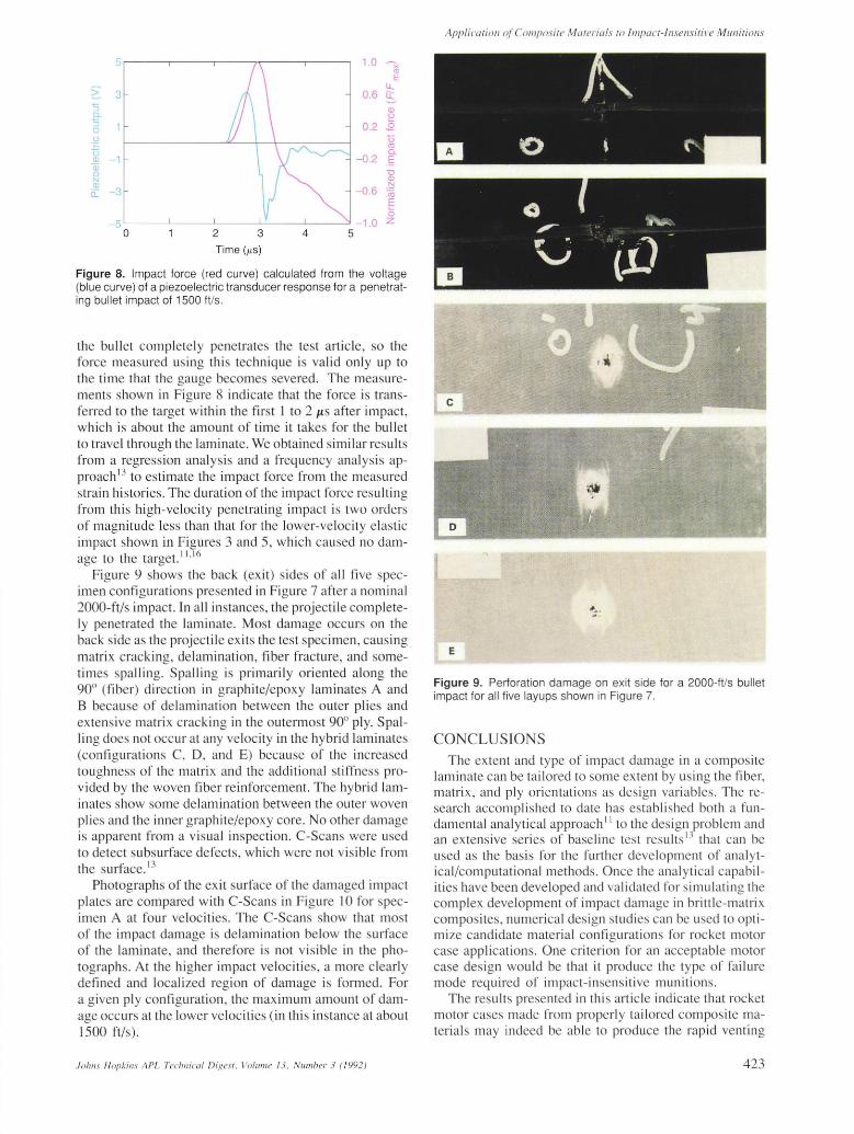
voltage output fro m the piezoelectric film gauge, the results of which are shown in Figure 8 for a lS00-ft/s impact. At the high impact velocities used in these tests,
Figure 8. Impact force (red curve) calculated from the voltage (blue curve) of a piezoelectric transducer response for a penetrating bullet impact of 1500 ft/s.
the bullet completely penetrates the test article, so the force measured using this technique is valid only up to the time that the gauge becomes severed. The measurements shown in Figure 8 indicate that the force is transfen-ed to the target within the first 1 to 2 I-tS after impact, which is about the amount of time it takes for the bullet to travel through the laminate. We obtained similar results from a regression analysis and a frequency analysis approach 13 to estimate the impact force from the measured strain histories. The duration of the impact force res ulting from this high-velocity penetrating impact is two orders of magnitude less than that for the lower-velocity elastic impact shown in Figures 3 and 5, which caused no damage to the target. 1
1.16
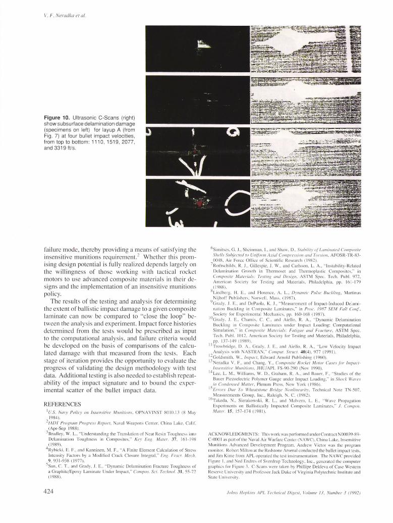
Figure 9 shows the back (exit) sides of all five specimen configurations presented in Figure 7 after a nominal 2000-ft/s impact. In all instances, the projectile completely penetrated the laminate. Most damage occurs on the back side as the projectile exits the test specimen, causing matrix cracking, delamination, fiber fracture, and sometimes spalling. Spalling is primarily oriented along the 90° (fiber) direction in graphite/epoxy laminates A and B because of delamination between the outer plies and extensive matrix cracking in the outermost 90° ply. Spalling does not occur at any velocity in the hybrid laminates (configurations C, D, and E) because of the increased toughness of the matri x and the additional stiffness provided by the woven fiber reinforcement. The hybrid laminates show some delamination between the outer woven plies and the inner graphite/epoxy core. No other damage is apparent from a visual inspection. C-Scans were used to detect subsurface defects, which were not visible from the surface. 13
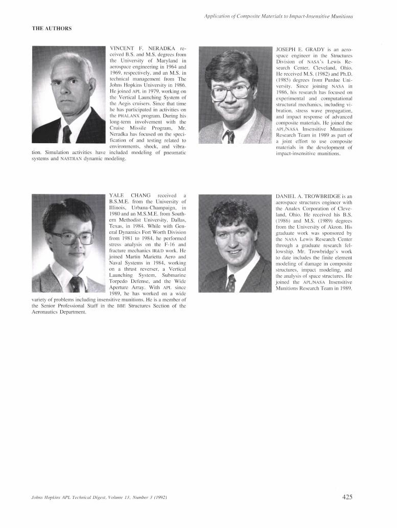
Photographs of the exit surface of the damaged impact plates are compared with C-Scans in Figure 10 for specimen A at four velocities. The C-Scans show that most of the impact damage is delamination below the surface of the laminate, and therefore is not visible in the photographs. At the higher impact velocities, a more clearly defined and localized region of damage is formed. For a given ply configuration, the maximum amount of damage occurs at the lower velocities (in thi s instance at about 1500 ft/s).
AppliCaliOIl o{Composite Materials to fmpacf-fllsensiti1 'e MUllitiolls
E
Figure 9. Perforation damage on exit side for a 2000-ft/s bullet impact for all five layups shown in Figure 7.
CONCLUSIONS The extent and type of impact damage in a composite
laminate can be tailored to some extent by using the fiber, matrix , and ply orientations as design variables. The research accomplished to date has establ ished both a fundamental analytical approach 11 to the design problem and an extensive series of baseline test results 13 that can be used as the basis for the further development of analytical/computational methods. Once the analytical capabi lities have been developed and validated for simulating the complex development of impact damage in brittle-matrix composites, numerical design studies can be used to optimize candidate material configurations for rocket motor case applications. One criterion for an acceptable motor case design would be that it produce the type of failure mode required of impact-insensitive munitions.
The results presented in thi s article indicate that rocket motor cases made from properly tailored composite materials may indeed be able to produce the rapid venting
423
V. F. Neradka ef al.
Figure 10. Ultrasonic C-Scans (right) show subsurface delamination damage (specimens on left) for layup A (from Fig. 7) at four bullet impact velocities , from top to bottom: 1110, 1519, 2077, and 3319 ft/s.
fai lure mode, thereby providing a means of sat isfy ing the in sensitive munitions requirement. 2 Whether this promising design potential is fully realized depends large ly on the wil lingness of those working with tactical rocket motors to use advanced composite materials in their designs and the implementation of an insensitive munitions policy.
The results of the testing and analysis for determining the extent of balli stic impact damage to a given composite laminate can now be compared to "close the loop" between the ana lysis and experiment. Impact force histories determined from the tests would be prescribed as input to the computationa l ana lysis, and fai lure criteria would be developed on the bas is of comparisons of the calculated damage with that measured from the tests. Each stage of iteration provides the opportunity to evaluate the progress of validating the design methodology with test data. Additional testing is also needed to establi sh repeatability of the impact signature and to bound the experimental scatter of the bullet impact data.
REFERENCES I U.S. N(II,), PoliCl' all Ill sellsilil'e Mun ilions , OPNAV I ST 80 10.1 3 (8 May
1984). 2fADT Program Progr ess Repol'/, aval Weapons Center. Chi na Lake. Ca lif.
(A pr-Sep 1988). 3Bradley, W. L. , "Understanding the Translation of Neat Resin Toughness into
Delamination Toughness in Composites," K ey Eng . Maler. 37, 16 1- 198 ( 1989).
4Rybicki , E. F .. and Kanninen, M. E , "A Finite Element Calculati on of Stress Intensi ty Factors by a Modified Crack Closure Integral. " Eng. FraCi. M cch. 9, 93 1-938 ( 1977).
5Sun, C. T. . and Grady. J. E .. " Dynamic Delaminati on Fracture Toughness of a Graphite/Epoxy Lam inate nder Impact ," Compos. Sci . Technof. 31 , 55-72 ( 1988).
424
6S imitses, G. J. , Shei nlll an , 1.. and Shaw, D .. Siahilill' o/Lalllina/cc/ COlllposile Shells Suh/c('/cd 10 Uniform Axial COlllprcssion and Torsion . AFOSR-TR-83-0048, Air Force Office of Scienti fic Research ( 1982).
7Rothschilds. R. J.. Gilles pie. 1. W. , and Carlsson. L. A .. " Instabil it y- Related Delam inati on Growth in Thermoset and Thermoplasti c Compos ites." in COIllf!osile Malerials: Tcsling and Design. ASTM Spec. Tec h. Publ. 972. American Society for Testing and Materi als, Philadelphi a, pp. 16 1- 179 ( 1988).
t; Lindberg, H. E., and Florence , A. L. , Dynamic Pufse Buckling, Martinus Nij hoff Publishers, orwell , Mass. ( 1987) .
9G rady, 1. E. , and DePao la . K. 1. , " Meas urement of Impact-Induced Delam inati on Buckl ing in Composite Laminates," in Proc. 1987 SEM Fall Conj:, Society for Experimenta l Mechanics, pp. 160-168 ( 1987).
IOG rady. J. E .. Chamis. C. c., and Aie llo. R. A. , " Dynamic Delaminati on Buckling in Compos ite Laminates under Impact Load ing: Computati ona l Simulation." in COIII/}()SiIC MOlerials: Faliglle and FraCiurc, ASTM Spec. Tech. Pub!. 1012. American Soc iety for Testing and Materia ls, Philadelphia, pp. 137- 149 ( 1989).
II Trowbridge, D. A .. Grady, J. E., and Aiell o, R. A., "Low Veloc ity Impact Analys is with ASTRA ," CO/JI/Jil/ . SOWI. 40(4), 977 (199 1).
11Goldsmith. W., f lllfJal'l. Edward Arnold Publi shing ( 1960). 13Neradka V. F .. and Chang, Y. , COlllposile Rockel M owr Cases for /mpaCI-
111.lelisilil 'e MIIIlilioll.\', JH U/APL FS-90-290 ( ov 1990). 1-1 Lee . L. Moo Williams, W. D., Graham , R. A .. and Bauer, F., "Studi es of the
Bauer Piezoelectric Polymer Ga uge under Impact Loading." in Shod W(II 'e.l· ill COlldensed MallCI'. Plen um Press, New York ( 1986) .
15 El'l'IJrs 0111' To Whealslolle Bl'idgc NOlifillCal'ilY. Technica l Note T -507 . Measurements Group, Inc., Raleigh, N. C. ( 1982) .
16Takeda, T , Sierakowski , R. L.. and Mal vern. L. E. , "Wave Propagati on Experiment s on Balli sti ca lly Impac ted Composite Laminates." .l . OlllfJOS. Maler. 15 , 157- 174 ( 1981).
ACKNOWLEDGMENTS: Th is work was performed under Cont rac t N00039-89-C-OOO I as part orthe Naval Air Warfare Center (NA WC). China Lake, In sensit ive Munitions Advanced Deve lopment Program. Andrew Victor was the program mon itor. Robert Milton at the Redstone Arsenal conducted the bul let impact test s, and Jim Kime from APL operated the test in strumentation. The A WC prov ided Figure I. and Ned End res of Sverdrup Technology. Inc. , generated the comp uter graphi cs for Figure 3. C-Scans we re taken by Phillipe Dek leva of Case Western Reserve ni versi ty and Professor Jac k Duke of Virginia Polytechnic Institute and State niversity.
Johlls H opkills APL Tec/lIlicaf Digesl. Vol lllll e 13 . NlImhel' 3 (1992 )
THE AUTHORS
VINCENT F. NERADKA received B.S . and M.S. degrees from the Uni ve rs ity of Maryland in ae rospace eng ineering in 1964 and 1969, respect ive ly, and an M.S . in techni ca l management from The Johns Hopk ins Univers it y in 1986. He joined APL in 1979, wo rking on the Verti ca l Launch ing System of the Aegis c rui sers. S ince that ti me he has participated in ac tiviti es on the PHA LANX program. During hi s long-tenn invo lvement with the Crui se Miss il e Prog ram , Mr. Neradka has focused on the specifica ti on of and testing related to environm ents, shock, and vi bra
tion. S imul ation activities have included modeling of pneumatic systems and NASTRAN dynam ic modeling.
Y ALE CHANG rece ived a B.S.M.E. from the Un ivers ity of Illinois , Urbana-Cham paig n, in 1980 and an M.S .M.E. from Southern Method ist U ni vers it y, Dall as, Texas, in 1984. While with Genera l Dynamics Fort Worth Di vis ion from 198 1 to 1984, he performed stress anal ysis on the F- 16 and fracture mechanics IR&D work. He joined Mart in Marietta Aero and Nava l Systems in 1984, work ing on a thru st reverser, a Ve rti ca l Launching System, S ubmarine Torpedo Defense, and the Wide Apel1ure Array. With APL s ince 1989, he has worked on a wide
variety of problems inc ludi ng insens itive munitions. He is a member of the Seni or Profess ional Staff in the BBE Structures Secti on of the Aeronautics Department.
Johns Hopkins APL Techllical Digesl. Volume 13, Number 3 (1992)
Applicotioll a/Composite Materials 10 Impact- In sensitil'e Munitions
JOSEPH E. G RADY is an aerospace e ng ineer in the S tructu res Divis ion of NASA's Lew is Research Cente r, C leveland , Oh io. He rece ived M.S. ( 1982) and Ph .D. ( 1985) degrees from Pu rdue U nive rsily. Since jo in ing NASA in 1986, hi s research has foc used on ex perimenta l and computational structural mec hanics, inc luding v ibration , stress wave pro pagation, and impac t response of advanced composite materia ls. He joi ned the APL/NASA Insens itive Mun iti ons Research Team in 1989 as part of a joint effort to use composite materials in the development of impact-insens iti ve munitions.
DANIEL A. TROWBRlDGE is an aerospace st ructures eng ineer w ith the Analex Corporati on of Cleveland, Ohio. He received his B.S. ( 1986) and M.S. ( 1989) degrees from the Unive rsity of Ak ron. Hi s g rad uate work was sponsored by the NASA Lew is Research Center through a grad uate research re llowsh ip. M r. Trowbridge' s work to date inc ludes the finite e lement mode ling of damage in composite structures , impact modeling, and the ana lysis of space struc tures . He joined the APLjNASA Insens itive M unitions Research Team in 1989.