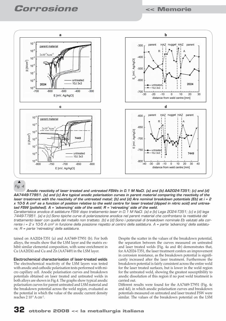
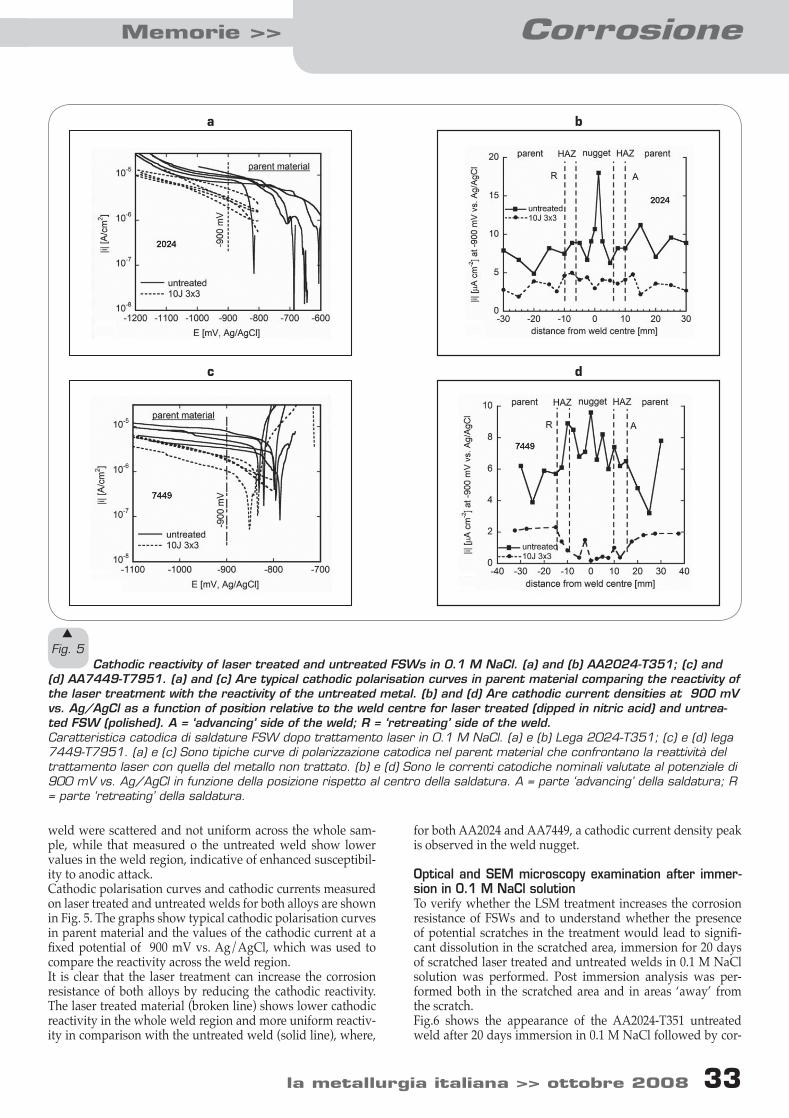
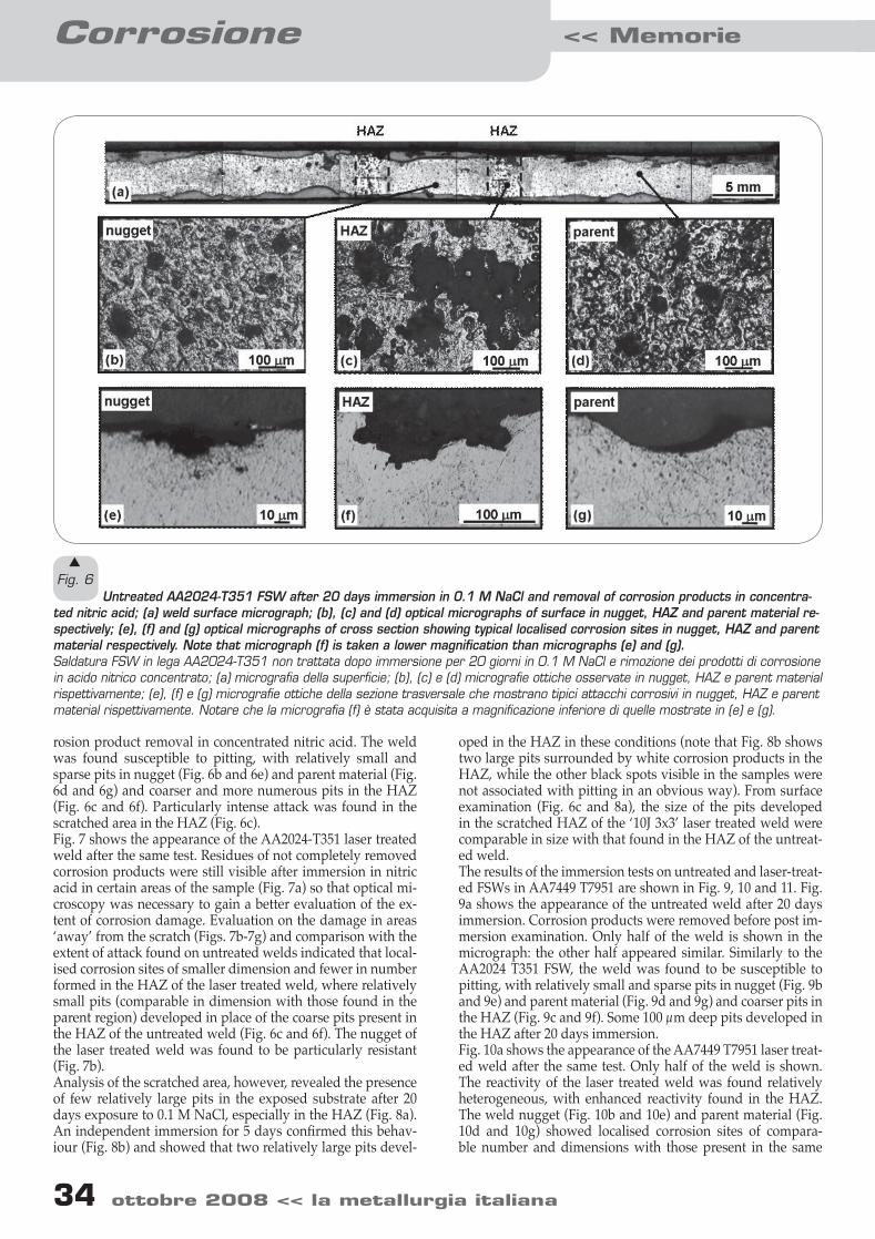
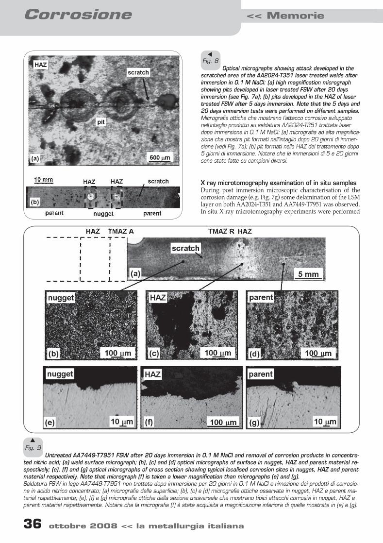
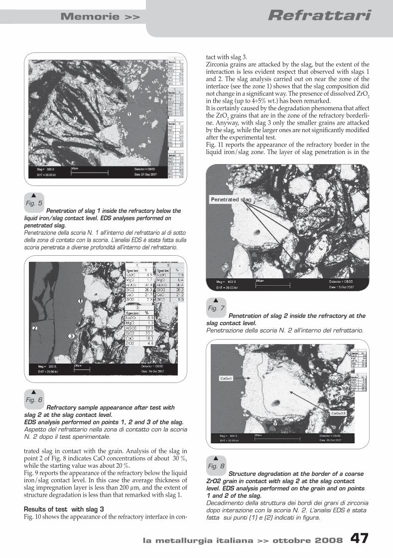
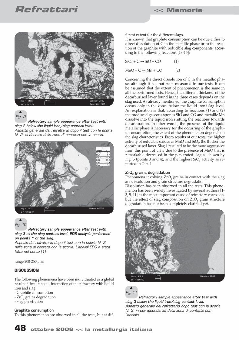
Acciaio inossidabile Memorie >> la metallurgia italiana >> ottobre 2008 3 APPLICATION OF DUPLEX STAINLESS STEEL FOR WELDED BRIDGE CONSTRUCTION IN AGGRESSIVE ENVIRONMENT G. Zilli, F. Fattorini, E. Maiorana Paper presented at the International Conference Duplex 2007, Grado, Italy, June 2007, organised by AIM Maintenance costs are a significant item in life cycle of steel bridges, becoming of paramount importance in aggressive environments. The use of duplex stainless steels for bridge decks would be a major step forward in providing durable, low maintenance structures, exploiting both their corrosion resistance and high mechanical properties, capable of meeting in full the required structural safety performances. A research project partially funded by the EU research programme RFCS (Research Fund for Coal and Steel, Bridgeplex contract RFS-CR-04040) is developing technical information on the use of duplex stainless steel in welded bridge construction via mechanical testing and numerical analyses, so as to provide indications suitable to form the basis for an upgrade of Eurocode 3 [1] and to allow a reliable Life Cycle Cost analysis for this kind of structures so as to address the best material choice for the future bridges. The project is still in progress but first results are available. This paper gives an overview of the project and summarizes results obtained, deeper detailed in other papers presented at the International Conference Duplex 2007 ([5] and [6]). In particular the paper is concerned with: · overview of critical details in a welded bridge deck and relevant data available in literature also on austenitic and austeno-ferritic steels; and · economical evaluations considering maintenance aspects and fabrication costs showing the advantages of the application of duplex stainless steel to defined bridge typologies. Keywords: duplex, stainless steel, bridge, construction, life cycle cost, maintenance INTRODUCTION Service life beyond 100 years is today the target of major infra- structure projects in the world, such as the longer and longer metallic suspension bridges. The capital investment involved is very high and planned maintenance costs are of overall impor- tance for the return on investment. Both safety and reliability become also of paramount importance because any tempo- rary closure is very expensive both in direct maintenance and repair and in traffic interruption. Giuliana Zilli Centro Sviluppo Materiali s.p.a., Italy Francesco Fattorini Centro Sviluppo Materiali s.p.a., Italy Emanuele Maiorana OMBA Impianti & Engineering s.p.a., Italy The aforementioned reasons lead to strongly consider du- plex stainless steels as construction material owing to their expected intrinsic corrosion resistance also in very aggressive atmosphere, assured by their chemical composition (22Cr 5Ni 3Mo 0.2N), and their high mechanical resistance due to their austeno-ferritic microstructure. Together with its intrinsic high cost, a major barrier to the use of duplex stainless steel in welded bridge construction is the lack of experimental data on both their mechanical charac- teristics and technological feasibility with respect to the spe- cific application, properties to be assessed if compared with the vast know-how available for traditional carbon steels. This paper will present an overview of the whole research ac- tivity ongoing in the frame of RFCS programme, highlighting the aspects investigated for the promotion of the use of duplex stainless steel in bridge construction. While specific techni- cal aspects related with the ability of duplex stainless steel
Transcript
Acciaio inossidabileMemorie >>
3 ottobre 2008 << la metallurgia italiana la metallurgia italiana >> ottobre 2008 3
APPLICATION OF DUPLEX STAINLESS STEEL FOR WELDED BRIDGE
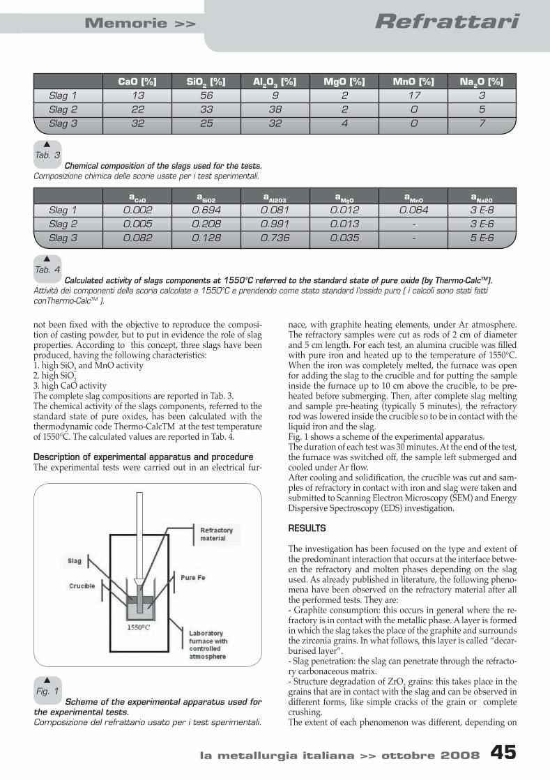
CONSTRUCTION IN AGGRESSIVE ENVIRONMENT
G. Zilli, F. Fattorini, E. Maiorana
Paper presented at the International Conference Duplex 2007, Grado, Italy, June 2007, organised by AIM
Maintenance costs are a significant item in life cycle of steel bridges, becoming of paramount importance in aggressive environments. The use of duplex stainless steels for bridge decks would be a
major step forward in providing durable, low maintenance structures, exploiting both their corrosion resistance and high mechanical properties, capable of meeting in full the required structural safety
performances. A research project partially funded by the EU research programme RFCS (Research Fund for Coal and Steel, Bridgeplex contract RFS-CR-04040) is developing technical information on the use of duplex stainless steel in welded bridge construction via mechanical testing and numerical analyses, so as to
provide indications suitable to form the basis for an upgrade of Eurocode 3 [1] and to allow a reliable Life Cycle Cost analysis for this kind of structures so as to address the best material choice for the future bridges.
The project is still in progress but first results are available. This paper gives an overview of the project and summarizes results obtained, deeper detailed in other papers presented at the International
Conference Duplex 2007 ([5] and [6]). In particular the paper is concerned with: · overview of critical details in a welded bridge deck and relevant data available in literature also on austenitic
and austeno-ferritic steels; and · economical evaluations considering maintenance aspects and fabrication costs showing the advantages of the
application of duplex stainless steel to defined bridge typologies.
Keywords: duplex, stainless steel, bridge, construction, life cycle cost, maintenance
INTRODUCTION
Service life beyond 100 years is today the target of major infra-structure projects in the world, such as the longer and longer metallic suspension bridges. The capital investment involved is very high and planned maintenance costs are of overall impor-tance for the return on investment. Both safety and reliability become also of paramount importance because any tempo-rary closure is very expensive both in direct maintenance and repair and in traffic interruption.
Giuliana Zilli Centro Sviluppo Materiali s.p.a., Italy
Francesco FattoriniCentro Sviluppo Materiali s.p.a., Italy
The aforementioned reasons lead to strongly consider du-plex stainless steels as construction material owing to their expected intrinsic corrosion resistance also in very aggressive atmosphere, assured by their chemical composition (22Cr 5Ni 3Mo 0.2N), and their high mechanical resistance due to their austeno-ferritic microstructure. Together with its intrinsic high cost, a major barrier to the use of duplex stainless steel in welded bridge construction is the lack of experimental data on both their mechanical charac-teristics and technological feasibility with respect to the spe-cific application, properties to be assessed if compared with the vast know-how available for traditional carbon steels. This paper will present an overview of the whole research ac-tivity ongoing in the frame of RFCS programme, highlighting the aspects investigated for the promotion of the use of duplex stainless steel in bridge construction. While specific techni-cal aspects related with the ability of duplex stainless steel
03-10 zilli+pubb.indd 3 13-10-2008 11:26:07
Acciaio inossidabile << Memorie
4 ottobre 2008 << la metallurgia italiana la metallurgia italiana >> ottobre 2008 5
4 ottobre 2008 << la metallurgia italiana la metallurgia italiana >> ottobre 2008 5
s
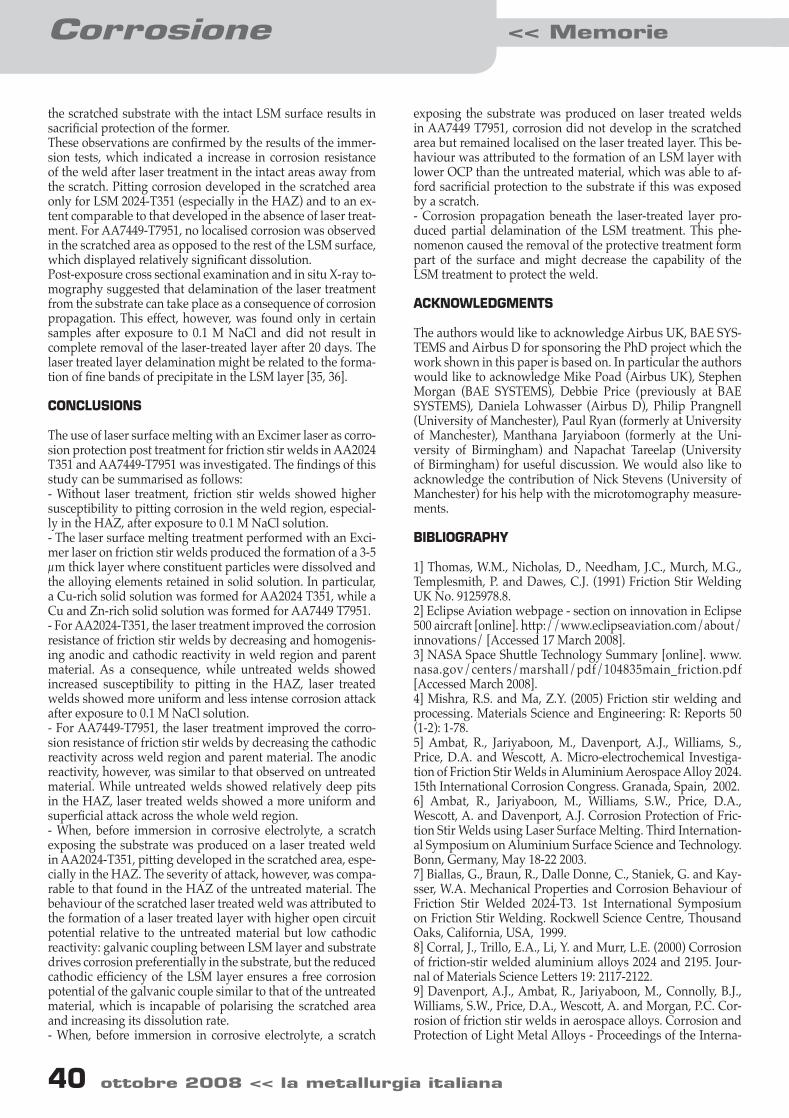
Fig. 1 Verrand viaduct view.
Viadotto Verrand a trave continua in lastra ortotropa (realizzato da OMBA).
to satisfy the bridge design requirements are here only intro-duced as their results are reported in other papers presented at the International Conference Duplex 2007 ([5] and [6]), here an overview of questions addressed and their effects in the view of Life Cycle Cost (LCC) evaluation are presented. CHOICE OF A BRIDGE CASE STUDY Steel bridges are increasingly using complex welded steelwork solutions to emphasise the lightness and aerodynamic shaping steel construction can offer. In this view the most diffuse con-structional typology, especially used in long span bridge deck construction, is the orthotropic deck. The boom of great bridges of the 1990’s concerns long-span suspension bridges.The main span length of cable-suspension bridges is nearing 2 km, which is currently more than twice that other bridge types can reach. The most long span suspension
bridges with the longer central span in the world (the Akashi Kaikyo Bridge, with central span of 1991 m and the Storebaelt East Bridge, with central span of 1624 m), finished at about one year time distance each other, are representative of two differ-ent constructive typologies of bridge: although both employ an orthotropic deck, due to the different cross-section geometries (one is a truss cross section while the other is a box section) have also two different flexural and torsional stiffeners and, conse-quently, different responses to the wind action [7]. It is important to note that with a similar constructive technique (orthotropic deck), are realized also bridges with medium length of span (from 100 m) as results from an overview of the most significant bridge typologies . Orthotropic deck is identified as the most interesting for the scope of this investiga-tion: that bridge typology contains all the critical welded details of the other bridge typologies and some other specific of orthotropic deck bridge.
s
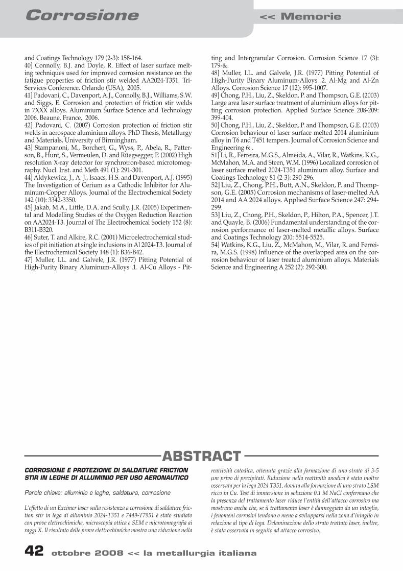
Fig. 2 Transversal section of the Verrand viaduct.
Sezione trasversale di lastra ortotropa (viadotto Verrand, OMBA).
03-10 zilli+pubb.indd 4 13-10-2008 11:26:08
4 ottobre 2008 << la metallurgia italiana la metallurgia italiana >> ottobre 2008 5
Acciaio inossidabileMemorie >>
4 ottobre 2008 << la metallurgia italiana la metallurgia italiana >> ottobre 2008 5
Consequently many research projects and experimental ac-tivities have been devoted in the recent past to study the in service behaviour of this complex steelwork leading to design and execution recommendations. But all of them were developed and verified on traditional constructional steel grades (i.e. S355 [8], [9], [10] and [11]). Although the duplex basic mechanical properties are well known, it is not enough to promote this material for huge weld-ed bridge construction but, because of the relevance of such a structure, more specific investigations on structural compo-nents typical of bridge structure are needed. Presently it is not possible to propose stainless steels for welded bridge construc-tion without having a similar experimental evidence of their applicability, although from the LCC point of view these ma-terials could have some advantages with respect to the more traditional solutions, when the expected service life is prolonged beyond two big maintenance intervention [12]. The existing bridge chosen to have a comparison between the utilization of carbon steel and duplex stainless steel, consider-ing both mechanical behaviour and durability during the whole service life with the scope of evaluating its Life Cycle Cost (LCC), is the Verrand viaduct (Fig. 1 and Fig. 2, [13]). The Verrand viaduct whose owner is R.A.V. spa, built in 2000 by OMBA of Torri di Quartesolo (Vicenza, Italy), is part of the Mont Blanc-Aosta highway, connecting Mont Blanc Tunnel with Morgex. The finishing of this part has permit to go to the Tunnel by an highway broad. The viaduct needed the realiza-
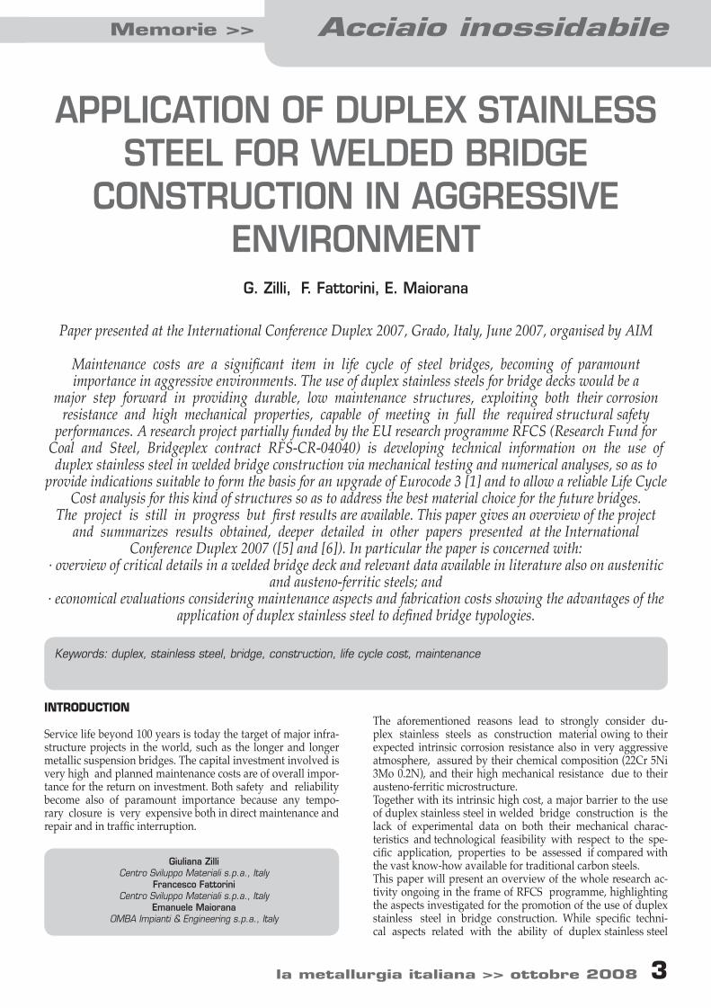
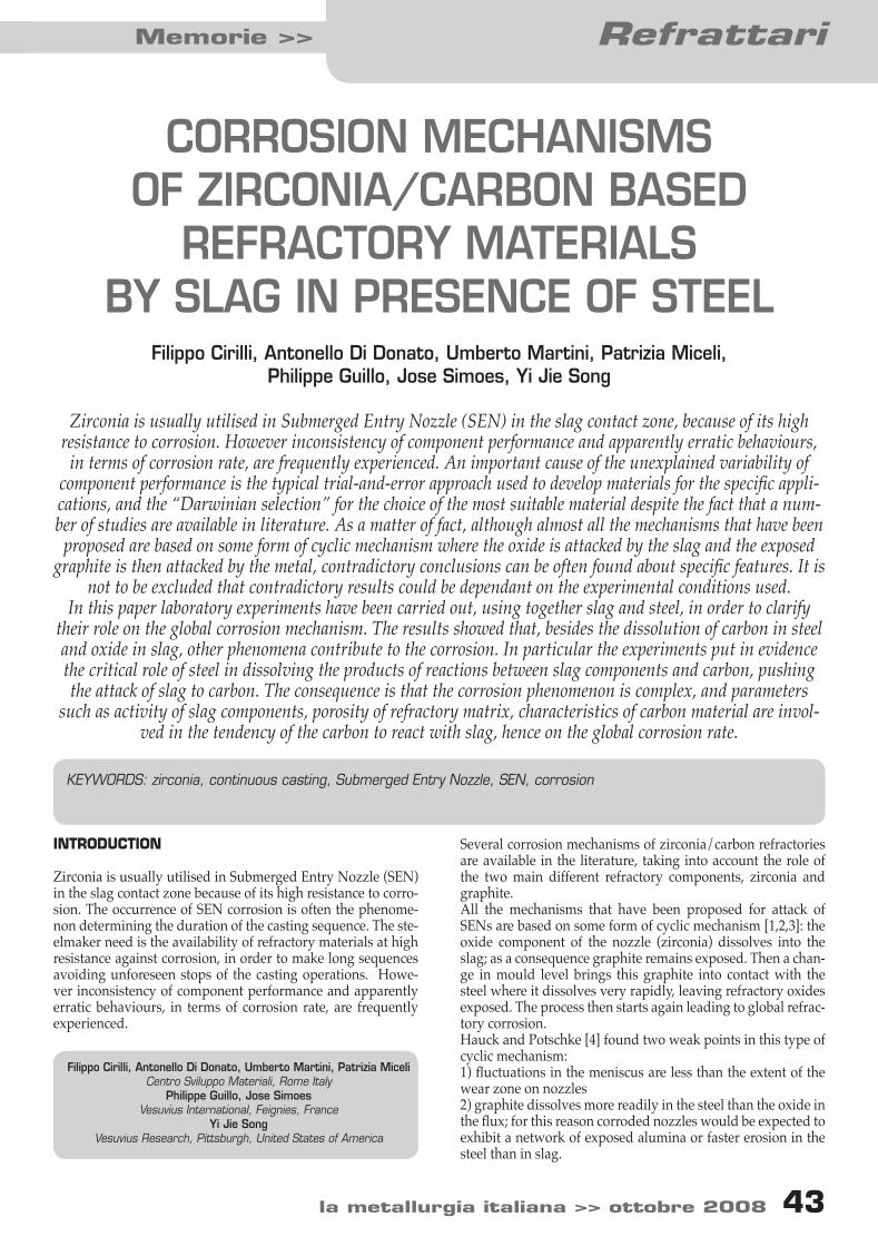
tions of long length spans, to have few intermediate piers, as for geodetics problems as to leave untouched the environ-mental and panoramic view: the Dora Baltea valley. CRITICAL DETAILS IDENTIFICATION Fatigue The bridge deck is the structural part mainly subjected to cy-clic loads (both railway and roadway actions) so as in many cases Fatigue Limit State [1] is the relevant one in design phase. Bridge deck can be made of different construction typologies but orthotropic deck is the most significant one in terms of fa-tigue problems: it presents a great number of welded details and some of them are particularly complex. An orthotropic deck consists of prefabricated deck modules welded at factory and joined together on site also by means of welding. The top plate joints are always welded on site, while beam elements joints can be either bolted or welded. In the transversal section of the Verrand bridge steel deck (Fig. 2,double-beam orthotropic deck) the transversal beams (T shaped section) are bolted; diaphragms and braces are made of bolted T or L profiles. Its static scheme is the continuum beam on a few supports. In Fig. 3 are shown the welded details se-lected for fatigue testing in the research project, results are pre-sented in the paper [6] at the International Conference Duplex 2007. Here below some of those are described also giving details on fabrication and welding procedures adopted, all being in ac-cordance with bridge construction practice and needs: - The edges of the top plate to be joined on site are usu-ally butt welded with a back ceramic support without back-ing run, to avoid the finishing of the weld on the back side. In that case the welding process is mixed: a first pass using the semi-automatic MAG – FCAW and the following passes (2nd4nth) by the automatic SAW process. Clamps are needed to align the plates and to keep the back ceramic support. The clamps are bolted to threaded studs welded on the bottom edge of the top plate, close to the edges to be joined (see Detail A.5 and A.6 of Fig. 3). - Corresponding to the transversal top plate joint of the deck modules it is necessary also to replace the continuity of the longitudinal ribs of the orthotropic deck: the way is to butt weld on site a piece of rib using a support plate (see Detail B.2 of Fig. 3). Large effort was made in the past for assessing the fatigue design curves of full-scale components typical of orthotropic deck, leading also to design indications incorporated in Eurocode 3 [1] for design of steel structures. Eurocode 3 [4] proposes the S-N curves approach for fatigue design, and it classifies a set of structural details assigning them specific design S-N curves.
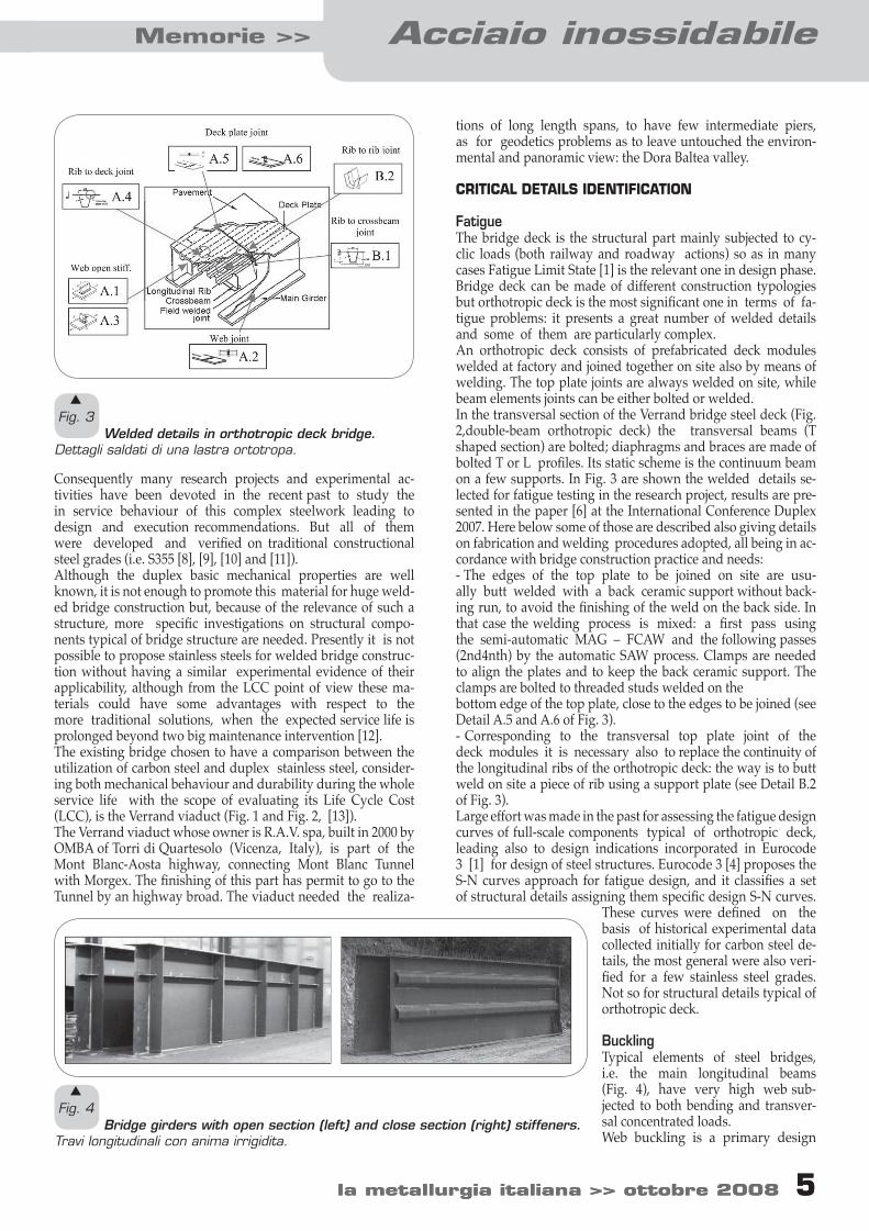
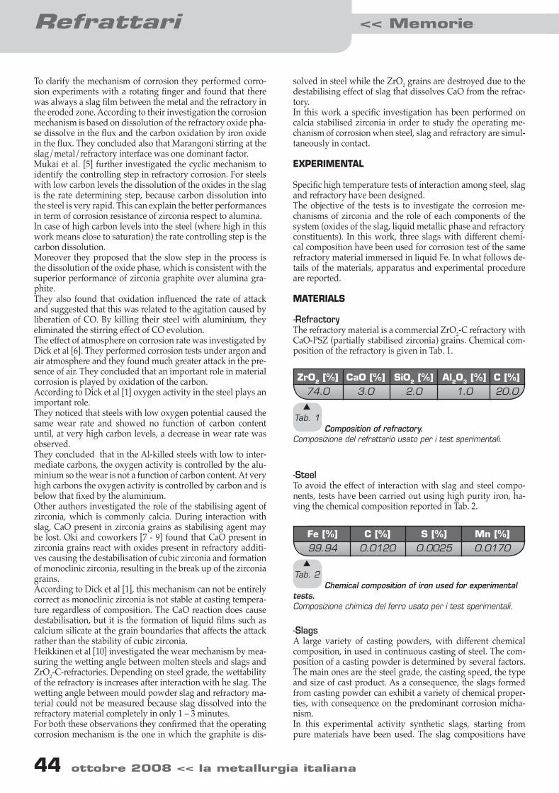
These curves were defined on the basis of historical experimental data collected initially for carbon steel de-tails, the most general were also veri-fied for a few stainless steel grades. Not so for structural details typical of orthotropic deck. Buckling Typical elements of steel bridges, i.e. the main longitudinal beams (Fig. 4), have very high web sub-jected to both bending and transver-sal concentrated loads. Web buckling is a primary design
s
Fig. 3 Welded details in orthotropic deck bridge.
Dettagli saldati di una lastra ortotropa.
s
Fig. 4 Bridge girders with open section (left) and close section (right) stiffeners.
Travi longitudinali con anima irrigidita.
03-10 zilli+pubb.indd 5 13-10-2008 11:26:08
Acciaio inossidabile << Memorie
6 ottobre 2008 << la metallurgia italiana la metallurgia italiana >> ottobre 2008 7
6 ottobre 2008 << la metallurgia italiana la metallurgia italiana >> ottobre 2008 7
criterion for such a structural element. Moreover, the re-petitiveness of low load levels, apart from fatigue problems, can get an unsafe accumulation of plastic strain due to the non-linearity of the s-e curve before the conventional yielding stress Rp0.2%. As results from an overview of data available in literature on ultimate shear resistance (Vult) of plate girders only a few tests are performed on stainless steel girders. It means that the now available design methods [3] are established especially on the basis of traditional carbon steel behaviour although stainless steel has clearly different mechanical properties related to its anisotropic and nonlinear behav-iour. The ultimate shear strength of plate girders with a slender web is especially contributed by the so- called post critical strength reserve, which develops once the shear stress in the web has reached the elastic critical shear buckling stress. All the models developed for the evaluation of the ultimate shear resistance are based on a similar basic idea according to which this resistance is composed of two main contributions: - The “web contribution” , i.e. the elastic critical shear buckling resistance of the web; - The so-called “flange contribution” reflecting the fact that, once the web has buckled, the web is still able to act as a pseudo-diagonal of a truss member, the chords of this member being the flanges and the vertical struts being the transverse stiffeners. Once developed, these models were calibrated against a lot of experimental results obtained from tests on specimens made of carbon steel. The ultimate shear resistance of a slender I (unstiffened or transversely stiffened) plate girder may exceed very sig-nificantly the elastic critical shear buckling resistance of the web by an amount which depends on both web slen-derness and rigidity of the flanges. Of course the account for post-critical strength reserve is beforehand subordinated to the
requirement of sufficient ductility for the steel material that is well known to be a characteristic favourable to duplex stain-less steel. In the ongoing project both experimen-tal activities and numerical analysis are in progress to evaluate the performances of EN 1.4462 duplex stainless steel in the application to bridge girders construction but results are not yet available. Corrosion resistance Looking at the aggressiveness of sites, EN ISO 12944 Standard classifies five different growing levels, from C1 to C5. C5 comprises also a marine site with presence of aggressive pollutants, as the environment of suspension bridges in Japan, in Hong Kong and of the future Messina Strait Bridge can be classified. Corrosion rate of carbon steel in C5 sites is very significant and expected around 80-200mm/year. As a consequence, to preserve the struc-ture costly measures as long lasting paint-ing coating of both external and internal surfaces and/or continuous dehumidi-fication of closed volumes (with R.U.*
40% weathering corrosion rate is practically suppressed) are used. In Tab. 1 an example of such an high protective coating system is reported. EN 1.4462 duplex stainless steel grade selected for this ap-plied research activity (UNS S32205 produced by Industeel) is demonstrating the attitude to be applied without any corro-sion protection, also in class C5 environments and considering welding techniques for the specific application, as reported in the paper [5] of the Conference. Comparing life-cycle costs of alternative materials The life-cycle cost (LCC) is evaluated on the basis of ASTM E917-05 “Standard practice for measuring life-cycle costs of buildings and building systems” [16]. LCCs of alter-native structural material choice for the same bridge deck are compared. In particular EN 1.4462 unprotected stainless steel is taken as an alternative to S460 painted steel. Experimental activities performed during the research project confirmed the duplex stainless steel alternative material sat-isfies the project requirements (structural safety and in-tegrity, reliability, environmental) under the same operational conditions of Verrand bridge but considering a class C5 envi-ronment. That is a fundamental assumption when compar-ing the LCCs of alternatives in general. Considering the attitude of duplex stainless steel to be placed in service without any corrosion protection, that is also in very aggressive environments classifiable as C5 (EN ISO 12944), the most sensitive parameters to be assessed in LCC analysis are those related with corrosion protective systems and their maintenance (cost of protective coatings, the cost and frequency of inspections and maintenance actions). With this respect it is important to note that those parameters are influenced by bridge owner standard practice and can vary by country to country, also techni-cal knowledge is always in progress and new protective systems can arise at the market. As a consequence in the fol-
s
Tab. 1 Paint system for general surface, corrosion category C 5.
Sistema di protezione dalla corrosione per una superficie generica in acciaio da costruzione e corrosività ambientale di categoria C5.
03-10 zilli+pubb.indd 6 13-10-2008 11:26:08
6 ottobre 2008 << la metallurgia italiana la metallurgia italiana >> ottobre 2008 7
Acciaio inossidabileMemorie >>
6 ottobre 2008 << la metallurgia italiana la metallurgia italiana >> ottobre 2008 7
lowing LCCs analysis a protective system for S460 steel bridge is considered which is among the more traditional ones due to the easier availability of data on. Maintenance schedul-ing is reported in Fig. 5. Some effects of alternative materials highlighted during both the fabrication of steelworks for testing and the evalu-ation of test results, are economically assessed in the present LCC analysis As regard the shop and yard productivity, the cost of austeno ferritic is considered 15% higher that follows by the balance between the faster welding rate and the more expensive weld-ing and cutting operations (see also paper [5] of the Confer-ence). The total quantity of the two material is the same as for the car-bon steel bridge as for the duplex bridge in accordance with the available mechanical test results. The increment in the fatigue behaviour of the austeno ferritic s.s. welded details shown by the testing activities [5] is assessed in the following LCC evaluations by not considering repair for fatigue costs during service life of duplex bridge. Only inspection (each year) and cleaning (every 9 years) are considered in the LCC evaluation of duplex alternative. Some of the effects of alternative materials are more difficult to quantify in monetary terms, that is the case of users costs re-lated with the reduction of speed or complete closure of the bridge. For example German Steel Association evaluates for ordinary maintenance operations 20 days of speed reduction from 120 km/h to 60 km/h, while for exceptional maintenance operations 40 days of speed reduction are expected. What this means in monetary terms is also difficult to be further evalu-ated but this aspect should be listed with the others and taken into account in the final evaluations. The LCCs of both bridge alternatives are calculated in present-value that means all costs are discounted to the base time (time of bridge construction). The study period is the expected service life for the bridge that is 100 years. LCC analyses are calculated in constant monetary value (net of gen-eral inflation). Bridge is treated as public utility infrastructure (non-profit building) so income tax effects are not included in the LCC analysis. The discount rate is a very sensitive pa-
rameter for LCCs comparisons with money savings mostly spreaded into the future, as in the present case study. Here two different real discount rates (net of general price in-flation) are used in the LCCs analysis:
Study period 100 years Real discount rate 3.2% and 1.8% Investment cost data S460 EN 1.4462 Material cost 1’100 €/t 5’500 €/t (2006 price) 3’000 €/t (2001 price) Shop cost 320 €/t 420 €/t Yard assembly cost 160 €/t 185 €/t Assembly equipments 200 €/t 200 €/t Corrosion protective coating 35 €/m2 0 Scaffolding and protections included Maintenance cost data Inspection 4 €/t 4 €/t Cleaning 50 €/t - Top coating (high performance system) 25 €/m2 - Coating renewal 35 €/m2 0 Scaffolding and protections included Repair for corrosion (% of initial investment) 5.16% - Repair for fatigue(% of initial investment) 12.3% - User costs related with reduction of service or closure of the bridge during maintenance operations are not monetary evaluated but should be taken into account in the comparison. End of service resale S460 EN 1.4462 30% 75% of material cost The results of LCC evaluations are reported and compared in
Fig. 5
Maintenance timing of painting systems for S460 of two different performance levels.Programma d’ispezione e manutenzione per la protezione dalla corrosione di ponti metallici in ambiente di categoria C5.
s
03-10 zilli+pubb.indd 7 13-10-2008 11:26:08
Acciaio inossidabile << Memorie
8 ottobre 2008 << la metallurgia italiana la metallurgia italiana >> ottobre 2008 9
8 ottobre 2008 << la metallurgia italiana la metallurgia italiana >> ottobre 2008 9
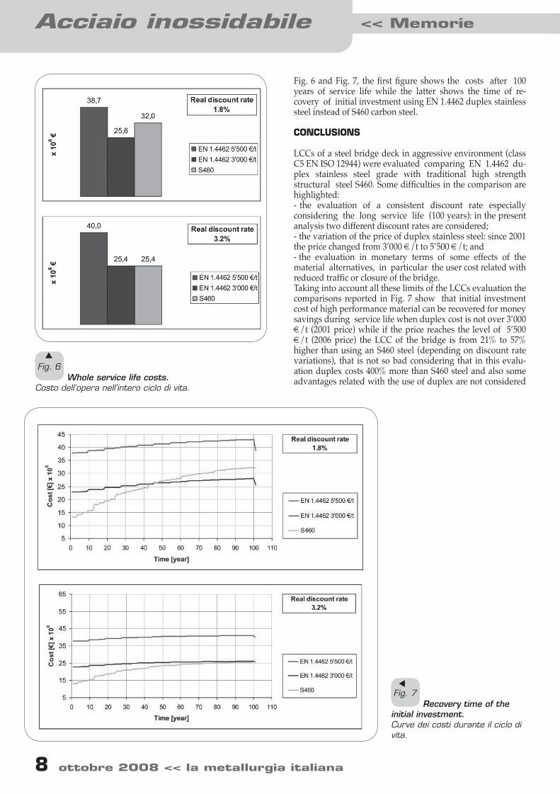
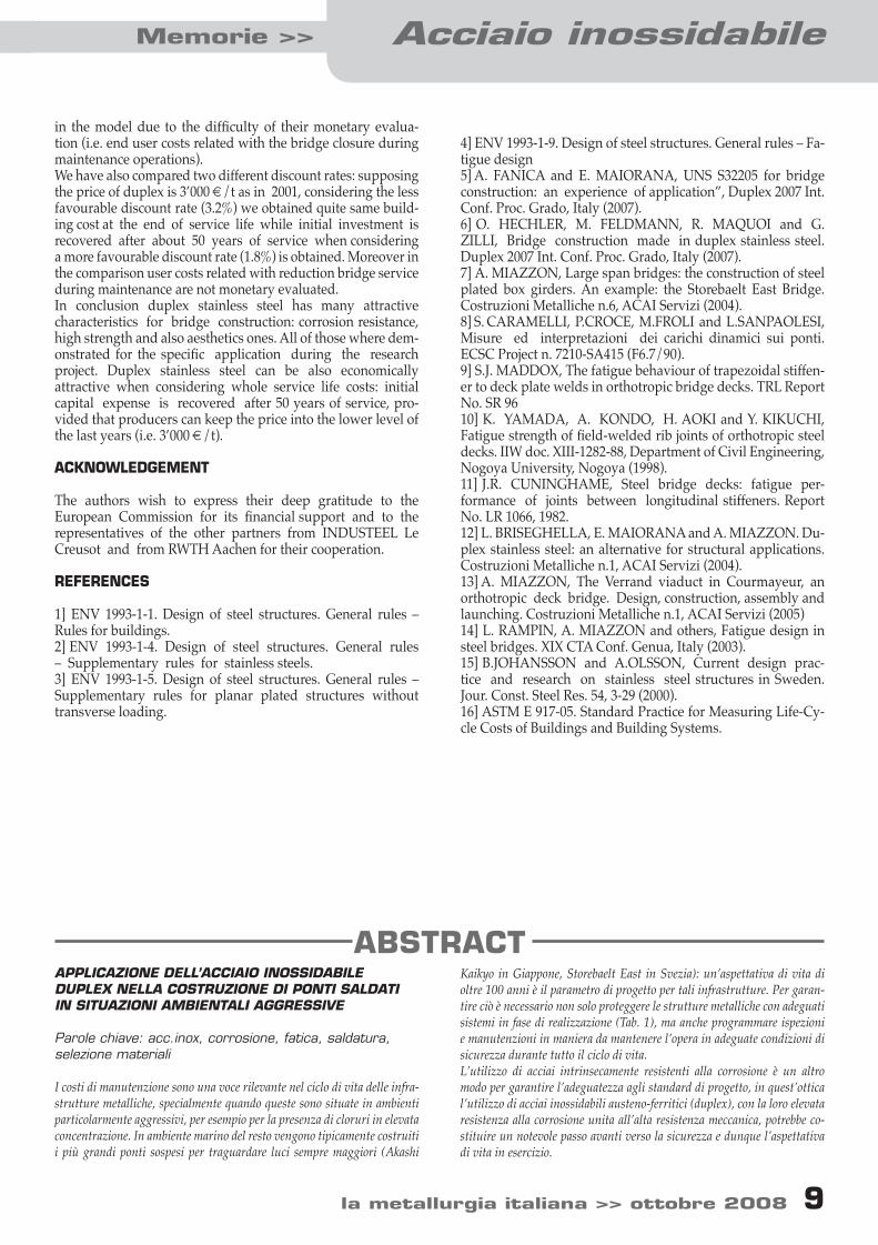
Fig. 6 and Fig. 7, the first figure shows the costs after 100 years of service life while the latter shows the time of re-covery of initial investment using EN 1.4462 duplex stainless steel instead of S460 carbon steel.
CONCLUSIONS LCCs of a steel bridge deck in aggressive environment (class C5 EN ISO 12944) were evaluated comparing EN 1.4462 du-plex stainless steel grade with traditional high strength structural steel S460. Some difficulties in the comparison are highlighted: - the evaluation of a consistent discount rate especially considering the long service life (100 years): in the present analysis two different discount rates are considered; - the variation of the price of duplex stainless steel: since 2001 the price changed from 3’000 €/t to 5’500 €/t; and - the evaluation in monetary terms of some effects of the material alternatives, in particular the user cost related with reduced traffic or closure of the bridge. Taking into account all these limits of the LCCs evaluation the comparisons reported in Fig. 7 show that initial investment cost of high performance material can be recovered for money savings during service life when duplex cost is not over 3’000 €/t (2001 price) while if the price reaches the level of 5’500 €/t (2006 price) the LCC of the bridge is from 21% to 57% higher than using an S460 steel (depending on discount rate variations), that is not so bad considering that in this evalu-ation duplex costs 400% more than S460 steel and also some advantages related with the use of duplex are not considered
s
Fig. 6 Whole service life costs.
Costo dell’opera nell’intero ciclo di vita.
Fig. 7 Recovery time of the
initial investment.Curve dei costi durante il ciclo di vita.
s
03-10 zilli+pubb.indd 8 13-10-2008 11:26:08
8 ottobre 2008 << la metallurgia italiana la metallurgia italiana >> ottobre 2008 9
Acciaio inossidabileMemorie >>
8 ottobre 2008 << la metallurgia italiana la metallurgia italiana >> ottobre 2008 9
in the model due to the difficulty of their monetary evalua-tion (i.e. end user costs related with the bridge closure during maintenance operations). We have also compared two different discount rates: supposing the price of duplex is 3’000 €/t as in 2001, considering the less favourable discount rate (3.2%) we obtained quite same build-ing cost at the end of service life while initial investment is recovered after about 50 years of service when considering a more favourable discount rate (1.8%) is obtained. Moreover in the comparison user costs related with reduction bridge service during maintenance are not monetary evaluated. In conclusion duplex stainless steel has many attractive characteristics for bridge construction: corrosion resistance, high strength and also aesthetics ones. All of those where dem-onstrated for the specific application during the research project. Duplex stainless steel can be also economically attractive when considering whole service life costs: initial capital expense is recovered after 50 years of service, pro-vided that producers can keep the price into the lower level of the last years (i.e. 3’000 €/t). ACKNOWLEDGEMENT The authors wish to express their deep gratitude to the European Commission for its financial support and to the representatives of the other partners from INDUSTEEL Le Creusot and from RWTH Aachen for their cooperation. REFERENCES 1] ENV 1993-1-1. Design of steel structures. General rules – Rules for buildings. 2] ENV 1993-1-4. Design of steel structures. General rules – Supplementary rules for stainless steels. 3] ENV 1993-1-5. Design of steel structures. General rules – Supplementary rules for planar plated structures without transverse loading.
4] ENV 1993-1-9. Design of steel structures. General rules – Fa-tigue design 5] A. FANICA and E. MAIORANA, UNS S32205 for bridge construction: an experience of application”, Duplex 2007 Int. Conf. Proc. Grado, Italy (2007). 6] O. HECHLER, M. FELDMANN, R. MAQUOI and G. ZILLI, Bridge construction made in duplex stainless steel. Duplex 2007 Int. Conf. Proc. Grado, Italy (2007). 7] A. MIAZZON, Large span bridges: the construction of steel plated box girders. An example: the Storebaelt East Bridge. Costruzioni Metalliche n.6, ACAI Servizi (2004). 8] S. CARAMELLI, P.CROCE, M.FROLI and L.SANPAOLESI, Misure ed interpretazioni dei carichi dinamici sui ponti. ECSC Project n. 7210-SA415 (F6.7/90). 9] S.J. MADDOX, The fatigue behaviour of trapezoidal stiffen-er to deck plate welds in orthotropic bridge decks. TRL Report No. SR 96 10] K. YAMADA, A. KONDO, H. AOKI and Y. KIKUCHI, Fatigue strength of field-welded rib joints of orthotropic steel decks. IIW doc. XIII-1282-88, Department of Civil Engineering, Nogoya University, Nogoya (1998). 11] J.R. CUNINGHAME, Steel bridge decks: fatigue per-formance of joints between longitudinal stiffeners. Report No. LR 1066, 1982. 12] L. BRISEGHELLA, E. MAIORANA and A. MIAZZON. Du-plex stainless steel: an alternative for structural applications. Costruzioni Metalliche n.1, ACAI Servizi (2004). 13] A. MIAZZON, The Verrand viaduct in Courmayeur, an orthotropic deck bridge. Design, construction, assembly and launching. Costruzioni Metalliche n.1, ACAI Servizi (2005) 14] L. RAMPIN, A. MIAZZON and others, Fatigue design in steel bridges. XIX CTA Conf. Genua, Italy (2003). 15] B.JOHANSSON and A.OLSSON, Current design prac-tice and research on stainless steel structures in Sweden. Jour. Const. Steel Res. 54, 3-29 (2000). 16] ASTM E 917-05. Standard Practice for Measuring Life-Cy-cle Costs of Buildings and Building Systems.
ABSTRACTAPPLICAZIONE DELL’ACCIAIO INOSSIDABILE DUPLEX NELLA COSTRUZIONE DI PONTI SALDATI IN SITUAZIONI AMBIENTALI AGGRESSIVE
Parole chiave: acc.inox, corrosione, fatica, saldatura, selezione materiali
I costi di manutenzione sono una voce rilevante nel ciclo di vita delle infra-strutture metalliche, specialmente quando queste sono situate in ambienti particolarmente aggressivi, per esempio per la presenza di cloruri in elevata concentrazione. In ambiente marino del resto vengono tipicamente costruiti i più grandi ponti sospesi per traguardare luci sempre maggiori (Akashi
Kaikyo in Giappone, Storebaelt East in Svezia): un’aspettativa di vita di oltre 100 anni è il parametro di progetto per tali infrastrutture. Per garan-tire ciò è necessario non solo proteggere le strutture metalliche con adeguati sistemi in fase di realizzazione (Tab. 1), ma anche programmare ispezioni e manutenzioni in maniera da mantenere l’opera in adeguate condizioni di sicurezza durante tutto il ciclo di vita.L’utilizzo di acciai intrinsecamente resistenti alla corrosione è un altro modo per garantire l’adeguatezza agli standard di progetto, in quest’ottica l’utilizzo di acciai inossidabili austeno-ferritici (duplex), con la loro elevata resistenza alla corrosione unita all’alta resistenza meccanica, potrebbe co-stituire un notevole passo avanti verso la sicurezza e dunque l’aspettativa di vita in esercizio.
03-10 zilli+pubb.indd 9 13-10-2008 11:26:08
Acciaio inossidabile << Memorie
10 ottobre 2008 << la metallurgia italiana la metallurgia italiana >> ottobre 2008 10
Hannecard Italy – Roll Covering looking for Technical-Commercial Representative
with preferred experience in technical sales to steel or non ferro sector
Contact:Please send your CV with English or French front letter to Gunthram Cornelis, Group director Hannecard at [email protected] , with reference “Vacancy Technical Commercial Italy”
Hannecard Italy is specialised in the production of roller and sleeve coverings with rubber elastomers and polyurethanes. It is based in Castelnuovo Scrivia (AL). Since end of 2005 it makes part of the European leader for this products Hannecard (www.hannecard.com) with headquarters in Belgium, group of 350 collaborators. The current local company has a strong growth program is in exe-cution for the coming years. To further support this growth we are looking for an Technical-Commercial Representative. You will be responsible for the maintaining & reinforcing relationships with existent customers (OEMs & End users), as well as developing new customers. Our customers are in the sector of industry (steel, film, wood) and printing, converting and packaging. Your working area will be North to Central Italy. You have at least 3 to 5 year of successful sales experience in B2B of technical products or ser-vices. The experience from steel sector is highly recommended. We are looking for a sales professional, well organised, dynamic (4 days/week customer visits) who can win new customers based on technical competences. We offer technical training by specia-lists (incl. in our European sites) & a rich & challenging working environment.
Tuttavia, benché le caratteristiche meccaniche di base degli acciai inossida-bili duplex siano ben note, poco si conosce sul loro comportamento quando assemblati in componenti saldati di geometrie complesse, i.e. le lastre or-totrope (Fig. 3) largamente utilizzate negli impalcati di ponti di media e grandissima luce, soggetti ai carichi variabili del traffico. Componenti di questo tipo, sia per la loro complessità che per l’importanza strategica in termini di sicurezza, sono stati ampiamente testati in passato per gli ac-ciaio tradizionali da costruzione (i.e. S355) e spesso richiedono tutt’ora un design assisted by testing nelle opere di nuova realizzazione. Per colmare almeno parzialmente questo gap di conoscenza il Fondo di Ri-cerca per l’Acciaio ed il Carbone ha finanziato un progetto di ricerca (“Brid-geplex” RFS-CR-04040) sull’applicazione di acciaio duplex EN1.4462 alla costruzione di ponti in lastra ortotropa in ambienti aggressivi (i.e. classi-ficabili C5 secondo EN ISO 12944). Il progetto prevede la realizzazione, anche in piena scala, ed il testing di componenti saldati caratteristici della tipologia a lastra ortotropa ma realizzati in acciaio duplex EN1.4462.
In questo articolo, oltre a presentare sommariamente le attività del progetto, ci si sofferma in particolare sull’analisi dei costi del ciclo di vita, svolta sulla base delle informazioni tecniche ottenute durante tutto il progetto. I risultati sono incoraggianti ma non decisivi, in quanto il costo del duplex è molto variabile ed ha subito proprio nel periodo del progetto un notevole incremento (+83%). La fattibilità dell’applicazione con gli stessi livelli di sicurezza e nelle stesse condizioni di esercizio del caso studio viadotto Ver-rand, è stata dimostrata da un punto di vista tecnico mediante le attività di realizzazione della carpenteria, da una parte, di testing sperimentale e simulazioni al calcolatore dei carichi di esercizio dall’altra. L’acciaio duplex ha mostrato di essere competitivo anche economicamente rispetto ad un ac-ciaio da costruzione ad elevata resistenza (i.e. S460), in quanto si prevede un recupero dell’investimento iniziale a metà ciclo di vita (Fig. 7), rispar-miando tra l’altro il costo sostenuto dall’utente dell’infrastruttura dovuto alle chiusure anche se parziali per manutenzioni straordinarie e realizzando comunque un’opera dal valore intrinseco superiore.
03-10 zilli+pubb.indd 10 13-10-2008 11:26:09
SaldaturaMemorie >>
11 ottobre 2008 << la metallurgia italiana la metallurgia italiana >> ottobre 2008 11
WELD PROPERTIES OF SANDVIK SAF 2707 HD®
P. Stenvall, M. Holmquist
Super duplex stainless steels have found extensive use in the oil & gas industry and in other areas in the (petro-) chemical processing industry. The recently developed hyper duplex grade Sandvik SAF 2707HD® allows extension of the application range of austenitic-ferritic alloys into even more aggressive conditions.In most applications for Sandvik SAF 2707 HD the equipment needs to be welded. Hence, weldability is of
utmost importance for a stainless steel grade of this kind. Weld documentation was made for a number of joints to simulate various tube- and pipe applications. The welding method used was gas tungsten arc welding.
The joints were tested regarding mechanical properties, microstructure, pitting resistance and in some cases chloride stress corrosion resistance. The filler wire used, designated Sandvik 27.9.5.L, was developed
specifically for Sandvik SAF 2707 HD. Overlay welds were produced using submerged-arc welding and gas tungsten arc welding. The welds were documented regarding ductility, microstructure and pitting resistance. Tube-to-tube sheet welds were also
produced to document the weld behaviour and pitting resistance.
Super duplex stainless steels, such as UNS S32750, have been used for more than 15 years in various industrial segments with great success, e.g. offshore industry, oil refineries, chemical and petrochemical industry, and pulp and paper production [1, 2, 3, 4]. However, environmental requirements and raised productiv-ity demands have, in many areas, forced the end-users into re-circulation of process streams, with increased temperatures and increased pressures leading to more aggressive process environ-ments. In some cases the process environment has become too aggressive for the super duplex grades. Therefore, a new hyper duplex stainless steel has been developed for these aggressive conditions – Sandvik SAF 2707 HD (UNS S32707) [5, 6]. The typical chemical composition is shown in Tab. 1. Parallel to the development of this grade a new welding consumable has been developed, Sandvik 27.9.5.L [7]. Typical chemical composition is shown in Tab. 1. The composition of the filler wire is similar to
Peter Stenvall Sandvik Materials Technology, Sweden
Martin Holmquist Sandvik Materials Technology, The Netherlands
that of the base material. However, the nickel content is higher and the molybdenum and nitrogen contents are somewhat lower in the wire in order to optimize the weld metal properties. Weldability is an important feature for a duplex stainless steel intended for tubular and flat products since welding is the most common technique – and many times the only technique – for joining. Therefore, welding and weldability of SAF 2707 HD has been a vital part of the development work. So far two weld-ing processes have been documented – TIG (GTAW) and sub-merged-arc welding (SAW). Some of the results are presented in this paper.
EXPERIMENTAL
All-weld-metalAll-weld-metals were produced with both TIG and SAW. For mechanical testing the weld metals were produced in grooves according to AWS A5.9 and for the corrosion testing the weld
s
Tab. 1 Nominal chemical composition of SAF 2707 HD, filler
27.9.5.L and other material included in the investigations.Composizione chimica nominale dell’acciaio SAF 2707 HD, del filo d’apporto 27.9.5.L e dell’altro materiale impiegato.
ProductTube/pipe
FillerPlate*
DesignationSAF 2707 HD
27.9.5.LS355N
C (%)0.010.010.15
Mn (%)1
0.81.5
Cr (%)2727-
Ni (%)6.59-
Mo (%)4.84.6
-
N (%)0.40.3
-
Others (%) Co: 1Co: 1
-*) Low alloy steel plate used as base for overlay welding.
11-18 stenvall.indd 11 13-10-2008 14:15:24
Saldatura << Memorie
12 ottobre 2008 << la metallurgia italiana la metallurgia italiana >> ottobre 2008 13
12 ottobre 2008 << la metallurgia italiana la metallurgia italiana >> ottobre 2008 13
metals were produced as overlay welds in 6-8 layers.The TIG welds were produced with Ar + 2%N2 as shielding gas. Wire diameter was 1.6mm. Mechanized TIG was used. The submerged-arc welds were produced with Sandvik flux 15W, a basic flux intended for duplex grades and austenitic high alloyed grades. Wire diameter was 2.4mm. In both cases the heat input was kept below 1.5kJ/mm and the interpass temperature was kept below 100°C.The all-weld-metals were tested in the following way:1. Documentation of microstructures including measurement of ferrite contents using linear analysis.2. Evaluation of alloying vectors for the submerged-arc weld.3. Tensile testing at RT according to EN 10002-1 using turned specimens.4. Charpy-V impact toughness testing according to EN 10045-1. Testing was made at RT, -20°C, -40°C and -60°C. Three specimens were tested at each temperature. 5. Determination of critical pitting temperature (CPT) was made according to ASTM G48-03 Method E modified by Sandvik. (The same double specimens were used through out the CPT determi-nation instead of new specimens at each temperature as stated in ASTM G48-03 Method E.) The surfaces of the specimens were ground using 120-grit abrasive paper.6. Evaluation of resistance to chloride stress corrosion cracking was made in NaCl solution according to ASTM G123 using U-bend specimens according to ASTM G30. Four specimens per weld were tested. Total time for exposure was 1008h. The speci-mens were taken out of the solution for intermediate inspection five times.
Tube weldsGirth welds were produced in tubes with dim. 25.4 x 1,65mm. Square butt joint was used as joint preparation. Welding was per-formed with manual TIG using Ar + 2%N2 as shielding gas and pure N2 as root gas. Filler wire 1.6mm in diameter was used. The weld was made in one run and the top side was brushed subsequent to welding. The weld was not pickled after welding.The tube welds were tested in the following way:1. Tensile testing transverse the weld at RT according to EN 10002-1 using rectangular section specimen t x 10mm.2. Bend testing was made as root bend and face bend test accord-ing to ASME IX using two face bend specimens and two root bend specimens.3. Determination of critical pitting temperature (CPT) was made according to ASTM G48-03 Method E modified by Sandvik. (The same double specimens were used through out the CPT determi-nation instead of new specimens at each temperature as stated in ASTM G48-03 Method E.) Two specimens were used. The temperature increment was 2.5°C and the testing started at 40°C. Before testing the corrosion specimens were degreased but not pickled.4. Documentation of microstructures, including measurement of ferrite contents using linear analysis.
Pipe weldsGirth welds were also produced in pipes 168.28 x 7.11mm (ANSI 6” Sch 40). Here a U-groove was used with 15° bevel, 1.5mm land having 2.5mm extension and 2.5mm radius between the bevel and the extended land. Manual TIG was used with Ar + 2%N2 as shielding gas and pure N2 as root gas. Filler wire diameter was 1.6mm. The weld was made in ten runs and the top side was brushed subsequent to welding. The weld was not pickled after welding.The pipe weld was tested in the following way:
1. Tensile testing transverse the weld at RT according to EN 10002-1 using rectangular section specimen t x 10mm.2. Bend testing was made as root bend and face bend test accord-ing to ASME IX using two face bend specimens and two root bend specimens.3. Determination of critical pitting temperature (CPT) was made according to ASTM G48-03 Method E modified by Sandvik. (The same double specimens were used through out the CPT determi-nation instead of new specimens at each temperature as stated in ASTM G48-03 Method E.) Two specimens were used. The temperature increment was 2.5°C and the testing started at 40°C. Before testing the corrosion specimens were degreased but not pickled.4. Evaluation of resistance to chloride stress corrosion cracking was made in NaCl solution according to ASTM G123 using U-bend specimens according to ASTM G30. Four specimens were tested. The weld was located in the centre of the U-bend and transverse to the bend. Total time for exposure was 1008h. The specimens were taken out of the solution for intermediate in-spection five times.5. Documentation of microstructures including measurement of ferrite contents using linear analysis.
Overlay weldsOne overlay weld was made with TIG and two with SAW, using two different welding fluxes. The TIG weld was made in five layers using Ar + 2%N2 as shielding gas. The filler diameter was 1.6mm. The submerged-arc welds were made in three layers using flux 15W, a basic flux without any alloying elements, and flux 10SW, a neutral chromi-um compensating flux. The basicity (calculated according Bon-iszewski) of flux 15W is around 1.7 and the basicity of flux 10SW is around 1.0. The filler diameter was 2.4mm. The base material was S355N, 50mm in thickness.The overlay welds were tested in the following way:1. Transverse side bend testing was made according to ASME IX using four specimens per weld.2. Determination of critical pitting temperature (CPT) was made according to ASTM G48-03 Method E modified by Sandvik. (The same specimens were used through out the CPT determination instead of new specimens at each temperature as stated in ASTM G48-03 Method E.) Two specimens were used. The temperature increment was 2.5°C and the testing started at 40°C. The cor-rosion specimens were taken from layer 4 and 5 (top layer) of the TIG weld and from layer 3 (top layer) of the submerged-arc weld. The surfaces of the specimens were ground using 120-grit abrasive paper.3. Chemical analysis of top layer.4. Documentation of microstructure and determination of ferrite content in top layer using linear analysis.
Tube-to-tube sheet weldsThe overlay weld produced with SAW and flux 15W was also used for tube-to-tube sheet trials. Sandvik SAF 2707 HD heat exchanger tubes, 25.4 x 1.65mm, were used for the trials. Three holes were drilled in the overlay weld and the base material in carbon steel to simulate a tube sheet. The holes were placed in the corners of a triangle with the sides measuring 55mm, 55mm and 80mm between the corners. Hence the distances between the holes were 30mm and 55mm. The reason for this pitch was to be able to cut out corrosion specimens without destroying the neighbouring tube. The joint type was according to Fig. 1.The tube-to-tube sheet weld was tested in the following way:1. Microstructure documentation of weld metal and HAZ.
11-18 stenvall.indd 12 13-10-2008 14:15:24
12 ottobre 2008 << la metallurgia italiana la metallurgia italiana >> ottobre 2008 13
SaldaturaMemorie >>
12 ottobre 2008 << la metallurgia italiana la metallurgia italiana >> ottobre 2008 13
s
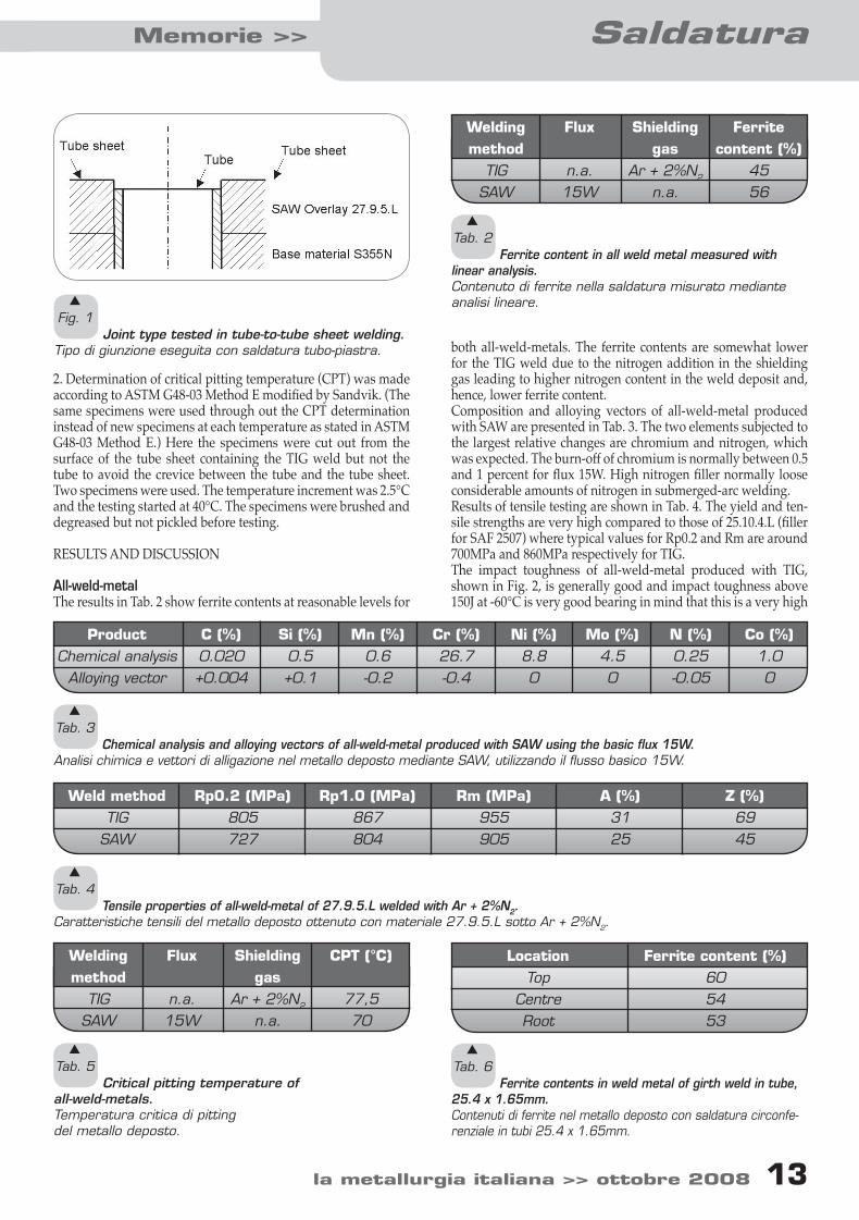
Fig. 1 Joint type tested in tube-to-tube sheet welding.
Tipo di giunzione eseguita con saldatura tubo-piastra. both all-weld-metals. The ferrite contents are somewhat lower for the TIG weld due to the nitrogen addition in the shielding gas leading to higher nitrogen content in the weld deposit and, hence, lower ferrite content.Composition and alloying vectors of all-weld-metal produced with SAW are presented in Tab. 3. The two elements subjected to the largest relative changes are chromium and nitrogen, which was expected. The burn-off of chromium is normally between 0.5 and 1 percent for flux 15W. High nitrogen filler normally loose considerable amounts of nitrogen in submerged-arc welding. Results of tensile testing are shown in Tab. 4. The yield and ten-sile strengths are very high compared to those of 25.10.4.L (filler for SAF 2507) where typical values for Rp0.2 and Rm are around 700MPa and 860MPa respectively for TIG.The impact toughness of all-weld-metal produced with TIG, shown in Fig. 2, is generally good and impact toughness above 150J at -60°C is very good bearing in mind that this is a very high
2. Determination of critical pitting temperature (CPT) was made according to ASTM G48-03 Method E modified by Sandvik. (The same specimens were used through out the CPT determination instead of new specimens at each temperature as stated in ASTM G48-03 Method E.) Here the specimens were cut out from the surface of the tube sheet containing the TIG weld but not the tube to avoid the crevice between the tube and the tube sheet. Two specimens were used. The temperature increment was 2.5°C and the testing started at 40°C. The specimens were brushed and degreased but not pickled before testing.
RESULTS AND DISCUSSION
All-weld-metalThe results in Tab. 2 show ferrite contents at reasonable levels for
Welding method
TIGSAW
Flux
n.a.15W
Shielding gas
Ar + 2%N2
n.a.
Ferrite content (%)
4556
s
Tab. 2 Ferrite content in all weld metal measured with
linear analysis.Contenuto di ferrite nella saldatura misurato mediante analisi lineare.
ProductChemical analysis
Alloying vector
C (%)0.020+0.004
Si (%)0.5+0.1
Mn (%)0.6-0.2
Cr (%)26.7-0.4
Ni (%)8.80
Mo (%)4.50
N (%) 0.25-0.05
Co (%) 1.00
s
Tab. 3 Chemical analysis and alloying vectors of all-weld-metal produced with SAW using the basic flux 15W.
Analisi chimica e vettori di alligazione nel metallo deposto mediante SAW, utilizzando il flusso basico 15W.
Weld methodTIG
SAW
Rp0.2 (MPa)805727
Rp1.0 (MPa)867804
Rm (MPa)955905
A (%)3125
Z (%) 6945
s
Tab. 4 Tensile properties of all-weld-metal of 27.9.5.L welded with Ar + 2%N2.
Caratteristiche tensili del metallo deposto ottenuto con materiale 27.9.5.L sotto Ar + 2%N2.
Welding method
TIGSAW
Flux
n.a.15W
Shielding gas
Ar + 2%N2
n.a.
CPT (°C)
77,570
s
Tab. 5 Critical pitting temperature of
all-weld-metals.Temperatura critica di pitting del metallo deposto.
LocationTop
CentreRoot
Ferrite content (%)605453
s
Tab. 6 Ferrite contents in weld metal of girth weld in tube,
25.4 x 1.65mm.Contenuti di ferrite nel metallo deposto con saldatura circonfe-renziale in tubi 25.4 x 1.65mm.
11-18 stenvall.indd 13 13-10-2008 14:15:25
Saldatura << Memorie
14 ottobre 2008 << la metallurgia italiana la metallurgia italiana >> ottobre 2008 15
14 ottobre 2008 << la metallurgia italiana la metallurgia italiana >> ottobre 2008 15
alloyed duplex filler material. It is interesting to note that the typical duplex behaviour for weld metals, where the curve shows a rather steep slope, is not present in the temperature interval tested. The slope is most likely present at lower temperatures. The TIG results at lower temperatures are somewhat strange showing an increase at the lowest temperature tested. This phenomenon might be an effect of limited basic data. For SAW the toughness level is lower which is expected since slag processes give higher oxygen contents in the weld metal and hence lower toughness. In addition, the ferrite content is higher in the SAW weld metal compared the TIG weld metal and this is also contributing, to lesser extent, to the difference in impact toughness. Still, the toughness is above 40J at -40°C indicating that SAW can be used down to -40°C with acceptable impact toughness.Critical pitting temperatures for the all-weld-metals are shown in Tab. 5. Both welding methods produce weld metals with very high CPT in comparison to that of all-weld-metals in the super duplex filler 25.10.4.L where CPT between 40 and 60°C have been reported [8, 9]. The results of SCC testing of the TIG all-weld-metal according to ASTM G123 with U-bend specimens according to ASTM G30 revealed no signs of stress corrosion cracking after testing for 1008h. The SAW all-weld-metal showed the same results after SCC test-ing for 1008h: No signs of stress corrosion cracking.
Tube weldsThe microstructures in weld metal and heat affected zone, shown in Fig. 3 and 4, are typical for duplex stainless steels. Ferrite con-tents in weld metal measured with linear analysis are shown in Tab. 6. The level is within the most common interval specified by standards and end users, 35-65% ferrite. There are no signs of intermetallic phases in weld metal or HAZ. Examples of the microstructures are shown in Fig. 2 and 3.Results of tensile testing are shown in Tab. 7. In spite of high ten-sile values the ruptures are located to the weld metals. Still, the tensile strength is clearly above the minimum value for SAF 2707 HD base material, which is 920MPa.
Face and root bend test according to ASME IX was carried out to 180° with approved results. Only one fissure appeared in one of the face bend specimens. However, the fissure was only 0.3mm which is approved according to ASME IX where discontinuities below 3mm are allowed. Critical pitting temperature of the tube weld was determined to 67.5°C, see Tab. 8. This level is markedly higher than that of weld-ed joints in SAF 2507 where the CPT is around 50°C [10, 11].
Pipe weldsThe microstructures in weld metal and heat affected zone, shown in Fig.5 and 6, are typical multi pass welds in duplex stainless steels. There are no signs of intermetallic phases in weld metal or HAZ.
s
Fig. 2 Charpy-V impact toughness of all-weld-metal
welded with TIG and SAW. TIG shielding gas: Ar + 2%N2. SAW flux: 15W (basic).IResilienza Charpy-V del metallo deposto mediante TIG e SAW. Gas di copertura TIG: Ar + 2%N2. flusso SAW: 15W (basico).
s
Fig. 3 Microstructure in centre of weld metal in
tube weld. Tube dim. 25.4 x 1.65mm. Magnification: 150x.Microstruttura al centro del metallo deposto in un tubo saldato ( dim. 25.4 x 1.65mm). Ingrandimento: 150x.
s
Fig. 4 Microstructure in HAZ and fusion line in tube
weld. Tube dim. 25.4 x 1.65mm. Magnification: 150x.Microstruttura nella ZTA e sulla linea di fusione in un tubo saldato ( dim. 25.4 x 1.65mm). Ingrandimento: 150x.
11-18 stenvall.indd 14 13-10-2008 14:15:25
14 ottobre 2008 << la metallurgia italiana la metallurgia italiana >> ottobre 2008 15
SaldaturaMemorie >>
14 ottobre 2008 << la metallurgia italiana la metallurgia italiana >> ottobre 2008 15
Ferrite contents in weld metal measured with linear analysis are shown in Tab. 9. The level is within the rather common interval specified by standards and end users, 35-65% ferrite. Results of tensile testing are shown in Tab. 10. The ruptures are located in the parent material about 15mm from the fusion line. Face and root bend test according to ASME IX was carried out to 180° with approved results. One fissure measuring 1.5mm ap-peared in one root bend specimen. However, according to ASME IX this is approved.Critical pitting temperature of the pipe weld was determined to 60°C, see Tab. 11. This value is lower than that of the tube weld described above, but it still is higher than that of SAF 2507 welds where the CPT is around 50°C [9, 10, 11]. With a further optimi-sation of the weld procedure used, a higher CPT for this type of multi-layer joint weld should be possible. The results of SCC testing according to ASTM G123 with U-bend specimens according to ASTM G30 revealed no signs of stress corrosion cracking after testing for 1008h. These results were expected since duplex stainless steels normally have very good
resistance to chloride induced stress corrosion cracking.
Overlay weldsThe basic flux designated 15W produce a surprisingly smooth and sound overlay weld with no signs of porosity on the surface. Slag removal was good and no slag remnants could bee noted.
Test temperature (°C)
RT
Specimen no.12
Rm (MPa)970966
Location of rupture Weld metalWeld metal
s
Tab. 7 Results of tensile testing transverse girth weld in tube 25.4 x 1.65mm.
Risultati delle prove di trazione trasversale in tubi ( dim 25.4 x 1.65mm ) con saldatura circonferenziale.
Specimen no.12
Attack temp. (°C)67.570
Location of attackWeld metal, top and root side.Weld metal, top and root side.
CPT (°C)
67.5
s
Tab. 8 Result of CPT determination of girth weld in tube, 25.4 x 1.65mm.
Risultato della determinazione della CPT in tubi ( dim 25.4 x 1.65mm ) con saldatura circonferenziale.
s
Fig. 5 Microstructure in centre of weld metal in pipe weld.
Pipe dim. 168 x 7,1mm. Magnification: 150x.Microstruttura al centro del metallo deposto in una saldatura di tubazione ( dim. 168 x 7,1mm). Ingrandimento: 150x.
s
Fig. 6 Microstructure in HAZ and fusion line in pipe weld.
Pipe dim. 168 x 7,1mm. Magnification: 150x.Microstruttura nella ZTA e sulla linea di fusione in una salda-tura di tubazione( dim. 168 x 7,1mm). Ingrandimento: 150x.
LocationTop
CentreRoot
Ferrite content (%)604643
s
Tab. 9 Ferrite contents in weld metal of girth weld in pipe,
168 x 7.1mm.Contenuto di ferrite nel metallo deposto con saldatura circonfe-renziale in tubazioni ( dim 25.4 x 1.65mm).
11-18 stenvall.indd 15 13-10-2008 14:15:25
Saldatura << Memorie
16 ottobre 2008 << la metallurgia italiana la metallurgia italiana >> ottobre 2008 17
16 ottobre 2008 << la metallurgia italiana la metallurgia italiana >> ottobre 2008 17
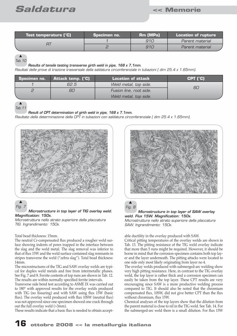
Total bead thickness: 15mm.The neutral Cr-compensated flux produced a rougher weld sur-face showing indents of pores trapped in the interface between the slag and the weld metal. The slag removal was inferior to that of flux 15W and the weld surface contained slag remnants in stripes transverse the weld (“zebra slag”). Total bead thickness: 14mm.The microstructures of the TIG and SAW overlay welds are typi-cal for duplex weld metals and free from intermetallic phases. See Fig. 7 and 8. Ferrite contents of top runs are shown in Tab. 12. The results are within normally specified ferrite intervals. Transverse side bend test according to ASME IX was carried out to 180° with approved results for the overlay welds produced with TIG (no fissuring) and with SAW using flux 15W (basic flux). The overlay weld produced with flux 10SW (neutral flux) was not approved since one specimen showed one crack through out the full overlay weld (>3mm). These results indicate that a basic flux is needed to obtain accept-
able ductility in the overlay produced with SAW.Critical pitting temperatures of the overlay welds are shown in Tab. 13. The pitting resistance of the TIG weld overlay indicate that more than 5 runs might be required. However, it should be borne in mind that the corrosion specimen contains both top lay-er and the layer underneath. The pitting attacks were located to one side only most likely originating from layer no 4.The overlay welds produced with submerged-arc welding show very high pitting resistance. Here, in contrast to the TIG overlay weld, the top layer is rather thick and a corrosion specimen can easily be taken from the top layer. These CPT results are very encouraging since SAW is a more productive welding process compared to TIG. It should also be noted that the chromium compensated flux, 10SW, did not give better CPT than the flux without chromium, flux 15W.Chemical analyses of the top layers show that the dilution from the parent material is close to nil in the TIG weld. See Tab. 14. For the submerged-arc weld there is a small dilution. For flux 15W
Test temperature (°C)
RT
Specimen no.12
Rm (MPa)910910
Location of rupture Parent materialParent material
s
Tab.10 Results of tensile testing transverse girth weld in pipe, 168 x 7,1mm.
Risultati delle prove di trazione trasversale della saldatura circonferenziale in tubazioni ( dim 25.4 x 1.65mm).
Specimen no.12
Attack temp. (°C)62.560
Location of attackWeld metal, top side.Fusion line, root side.Weld metal, top side.
CPT (°C)
60
s
Tab.11 Result of CPT determination of girth weld in pipe, 168 x 7.1mm.
Risultato della determinazione della CPT in tubazioni con saldatura circonferenziale ( dim 25.4 x 1.65mm).
s
Fig. 7 Microstructure in top layer of TIG overlay weld.
Magnification: 150x.Microstruttura nello strato superiore della placcatura TIG. Ingrandimento: 150x.
s
Fig. 8 Microstructure in top layer of SAW overlay
weld. Flux 15W. Magnification: 150x.Microstruttura nello strato superiore della placcatura SAW. Ingrandimento: 150x.
11-18 stenvall.indd 16 13-10-2008 14:15:25
16 ottobre 2008 << la metallurgia italiana la metallurgia italiana >> ottobre 2008 17
SaldaturaMemorie >>
16 ottobre 2008 << la metallurgia italiana la metallurgia italiana >> ottobre 2008 17
the composition is not far from that of all-weld metal in Tab. 3. It is also interesting to note that the chromium compensating flux 10SW is not giving any higher chromium content compared to flux 15W. Indeed, the dilution from parent material is somewhat larger with flux 10SW but this fact cannot explain why there was no effect of the chromium compensation flux. Obviously flux 15W is the best flux for this purpose, giving bet-ter weld bead appearance, approved bend test results and pitting resistance equal to are better than that of flux 10SW.
Tube-to-tube sheet weldsThe ferrite content in the tube-to-tube sheet weld was deter-mined to 33%. The microstructures of tube to tube sheet weld metals, HAZ in tube and HAZ in weld overlay are shown in Fig. 9 and 10. The microstructure in Fig. 9 and ferrite content of 33% indicate that the nitrogen content of the shielding gas can be low-ered to get a slightly higher ferrite level.Determination of pitting resistance in tube-to-tube sheet welds is difficult since the crevice between the tube and the tube sheet needs to be completely removed in order to avoid crevice corro-sion during the pitting test. Here the testing was carried out suc-cessfully and the CPT was determined to 60°C. See Tab. 15.
CONCLUDING REMARKS
It should be noted that the welded joints were not pickled,
ground or polished after welding meaning that the testing was made at fairly severe conditions. If the welds would have been pickled the CPT level would most likely have been even higher. However, the conditions used in these trials are more similar to real conditions, even though pickling of the top side of the weld is rather common.
Weld methodTIG
SAW
Fluxn.a.15W
10SW (Cr comp)
No. of layers533
Ferrite content (%) 536051
s
Tab.12 FFerrite contents of top layers in overlay welds.
Contenuti di ferrite negli strati superiori delle placcature.
Welding method
TIGSAW
Flux
n.a.15W
10SW (Cr comp)
No. of layers
533
Specimen 1
62.57570
Specimen 2
6572,572,5
Attack temp. (°C) CPT (°C)
62,572,570
s
Tab.13 Results of CPT determination of overlay welds.
Risultati delle determinazioni della CPT per le placcature.
Welding method
TIGSAWSAW
Flux
n.a.15W
10SW (Cr comp)
No. of layers
533
C (%)
0.0130.0200.017
Mn (%)
0.80.60.5
Cr (%)
27.026.426.2
Ni (%)
8.88.68.4
Mo (%)
4.54.44.3
N (%)
0.300.240.26
s
Tab.14 Chemical analysis of top layers welded with
filler 27.9.5.L.Analisi chimica degli strati superficiali saldati con materia-le d’apporto 27.9.5.L.
s
Fig. 9 Microstructure in weld metal of tube-to-tube
sheet weld (TIG). Magnification: 300x.Microstruttura del metallo deposto nella saldatura TIG tubo-piastra . Ingrandimento: 300.
11-18 stenvall.indd 17 13-10-2008 14:15:25
Saldatura << Memorie
18 ottobre 2008 << la metallurgia italiana la metallurgia italiana >> ottobre 2008 18
The overlay welds show very good properties and the sub-merged-arc welds show surprisingly good properties, especially with regard to the limited amount of layers. These results indi-cate that SAW, from both a technical and economical point of view, is a good technique for producing a hyper duplex tube sheet surface. The encouraging results of the tube-to-tube sheet welding trials strengthen this indication.
CONCLUSIONS
A new hyper duplex stainless steel, SAF 2707 HD, and matching filler, 27.9.5.L, has been developed with good weldability. Documentation of various welds produced with TIG and SAW shows that the welds possess:- High strength – substantially better than that of SAF 2507/filler 25.10.4.L.- Good ductility.- Good impact toughness.
s
Fig. 10 Microstructure in HAZ of overlay weld in tub-
to-tube sheet weld. TIG weld metal to the right. HAZ in SAW overlay in the centre and to the left. Magnifica-tion: 150x.Microstruttura nella ZTA di una placcatura dopo salda-tura TIG tubo-piastra. Metallo saldato mediante TIG a destra; ZTA nella placcatura SAW al centro e a sinistra. Ingrandimento: 150 x.
- Good resistance to chloride induced stress corrosion cracking.- High pitting resistance – substantially better than that of SAF 2507/filler 25.10.4.L.
REFERENCES
1] J. M. A. QUIK, M. GEUDEKE, Chemical Engineering Progress 11, (1994), p.49.2] P. LØVLAND, Proc. 25th Annual Offshore Technology Con-ference, Houston, Texas (1993), OTC, Richardson, Texas (1993), p.529.3] H. LEONARD, F. STOLL, Stainless Steel World 4, (1997), p.55.4] K. C. BENDALL, Anti-Corrosion Methods and Materials 3, (1997) p.170.5] K. GÖRANSSON, M.-L. NYMAN, M. HOLMQUIST, E. GOMES: “Sandvik SAF 2707 HD (UNS S32707) – a hyper-du-plex stainless steel for severe chloride containing environments” (Houston, USA: Stainless Steel World Conference, 2006) P6003.6] K. GÖRANSSON, M. HOLMQUIST, M.-L. NYMAN, Corro-sion 2007, Nashville, Tennessee (2007), NACE, Houston, Texas (2007) paper no.07189.7] P. STENVALL, M. HOLMQUIST, Corrosion 2007, Nashville, Tennessee (2007), NACE, Houston, Texas (2007), paper No. 07190.8] C.-O. PETTERSSON, Internal Report no. T9801209, Sandvik Steel R&D, Sandviken (1998).9] S.-Å. FAGER, Proc. Duplex Stainless Steels, Beaune (1991), Les Editons de Physique, Les Ulis Cedix (1991), p.403.10] S.-Å. FAGER, L. ÖDEGÅRD, Proc. Third Internat. Offshore and Polar Conference, Singapore (1993), The Int. Soc. of Offshore and Polar Engineers (1993), p.416.11] S.-Å. FAGER, L. ÖDEGÅRD, Proc. Applications of Stainless Steels, Stockholm (1992), Jernkontoret (1992) p.307.
Specimen no.12
Attack temp. (°C)
6065
Location of attackT/TS weld
HAZ in overlay weld
CPT (°C)
60
s
Tab.15 Results of CPT determination of tube-to-tube sheet
welds.Risultati della determinazione della CPT per le saldature tubo-piastra.
ABSTRACTPROPRIETÀ DELLE SALDATURE IN ACCIAIO SANDVIK SAF 2707 HD®
Keywords: acciaio inossidabile, saldatura
Gli acciai inossidabili Super duplex, hanno trovato ampio impiego nell’industria petrolifera e in altri settori relativi alla chimica di tra-sformazione del petrolio. Il grado Hyper duplex SAF 2707HD ®, re-centemente sviluppato da Sandvik, consente l’estensione del campo di applicazione degli acciai austeno-ferritici a condizioni ancor più aggressive. Nella maggior parte delle possibili applicazioni dell’acciaio Sandvik SAF 2707 HD le attrezzature devono essere saldate, pertanto la saldabilità è estremamente importante per questo tipo di materiale.
E’ stata quindi prodotta una documentazione sulla saldatura di questo acciaio per molteplici tipi di giunzioni, al fine di simulare diverse ap-plicazioni in tubi e tubazioni. Il metodo di saldatura utilizzato è stato il TIG. Le giunzioni sono state sottoposte a prove per determinarne pro-prietà meccaniche, microstruttura, resistenza alla pitting (CPT-critical pitting temperature) e, in alcuni casi, la resistenza alla corrosione sot-to sforzo da cloruri. Il filo d’apporto utilizzato, denominato Sandvik 27.9.5.L, è stato sviluppato specificamente per l’acciaio Sandvik SAF 2707 HD. Sono state indagate anche placcature prodotte utilizzando l’arco sommerso e il metodo TIG, che sono state caratterizzate in termi-ni di duttilità, microstruttura e resistenza al pitting. Si sono poi realiz-zate anche saldature tubo-piastra per documentarne il comportamento e la resistenza al pitting.
11-18 stenvall.indd 18 13-10-2008 14:15:25
SaldaturaMemorie >>
19 ottobre 2008 << la metallurgia italiana la metallurgia italiana >> ottobre 2008 19
RESEARCH OF THE BEST TECHNOLOGICAL AND METALLURGICAL PARAMETERS FOR PERFORMING THE ELECTRIC RESISTANCE
WELDING OF LOW CARBON STEELS C. Mapelli, C. Corna
This work deals with the research of the optimal technological and metallurgical parameters in order to implement a reliable procedure for the electric resistive welding of low carbon structural steel, in order to evaluate the
conditions which can grant the best mechanical performances. Low carbon steels must be featured by high plastic formability properties, since the production process consists in the piping of a rolled band, followed by an Electric
Resistance Welding (ERW) of the edges. The optimal technological parameters have been identified performing welding tests at several levels of electric power, squashing length and forward velocity of the pipe along the coil axis. Several mechanical tests have been performed for the determination of the properties of the materials under examination, in order to characterize the main mechanical properties, i.e. Young modulus, yield and the ultimate stresses, yield point elongation (the strain after which the plastic behaviour takes place), anisotropy coefficients (rm, Δr), Vickers micro-hardness and hardening coefficient of the materials analysed, while the residual stress
induced in correspondence of the welded joining have been determined by X-ray diffraction. The microstructural characteristics of the steels have been obtained through micrographic analyses coupled with the use of Electron Back Scattered Diffraction techniques (EBSD). The value assumed by the hardening coefficient and by the yield
elongation point has been revealed to be a strongly significant parameter for assuring the quality of the joining in order to avoid a very early formation of the cracks in the welding region.
Keywords: electric resistive welding, cementite precipitation, hardening coefficient, yield elongation point, residual stresses
INTRODUCTION
This work is about the identification of the best technological pa-rameters of the steel properties which can grant the soundness of pipes realized by ERW high frequency welding. This process is based on the resistive heating of the edges of the steels which cross a volume contained in a coil interested by a current varying at high frequency (500-1000kHz). The time-variant magnetic flow induced by the coils current causes a potential difference and a related current which concentrates on the steel edges pro-ducing an intensive and concentrated heating (Fig. 1).Just after the heating, the strip edges are pulled against themsel-ves by the action of rollers. This is the system through which the welding operation is performed exploiting the High Frequency
Carlo Mapelli, Cristian Corna Sezione Materiali per Applicazioni Meccaniche
Dipartimento di Meccanica, Politecnico di Milano, via La Masa 34, 20156 MILANO (ITALY)
Fig. 1 Example of a simulation showing the layout of the
system and the resistive heating produced on the pipe edges to be joined.Esempio di una simulazione che mostra il layout del sistema e il riscaldamento prodotto sulle estremità del tubo che devono essere saldate.
19-27 mapelli.indd 19 13-10-2008 10:58:30
Saldatura << Memorie
20 ottobre 2008 << la metallurgia italiana la metallurgia italiana >> ottobre 2008 21
20 ottobre 2008 << la metallurgia italiana la metallurgia italiana >> ottobre 2008 21
Electric Resistance Welding process: the two metallic edges are pressed by the welding-rollers and brought to fusion by the Jou-le effect1,2,3,4,5,6)(Fig. 2).The rolled and annealed plates of Low Carbon steels know a wide use for the production of pipes, also for the good forma-bility attitude which can grant the realization of complex shape component through the forming of the welded pipes. The sy-stem and the steel characterization are necessary to understand the possible reasons which cause the formation of unacceptable micro-cracks near the seam of the welded steel (Fig. 3), because this type of failure forbids the use of the welded components (Fig. 4, Fig. 5).
EXPERIMENTAL PROCEDURES
The analysis has been performed on a Low Carbon Steel with a chemical composition largely used, in automotive fielda, for sport equipment applications etc. (Tab. 1). The welding
s
Fig. 2 Layout of a ERW system for pipe production.
Layout del sistema ERW per la produzione dei tubi.
s
Fig. 3 Example of the complex tubular shape realized
by plastic deformation of the welded pipes.Esempio delle complesse forme tubolari realizzate mediante deformazione plastica dei tubi saldati.
s
Fig. 4 Example of a micro-crack revealed near the
seam region of a welded steel plate.Esempio di una micro-cricca rivelata vicino alla regione di giunzione.
s
Fig. 5 Example of a fracture nucleated and grown
near non-metallic defects trapped within the seam.Esempio di una frattura nucleata e propagata in prossimità di inclusioni non metalliche intrappolate all’interno della regione di saldatura.
19-27 mapelli.indd 20 13-10-2008 10:58:30
20 ottobre 2008 << la metallurgia italiana la metallurgia italiana >> ottobre 2008 21
SaldaturaMemorie >>
20 ottobre 2008 << la metallurgia italiana la metallurgia italiana >> ottobre 2008 21
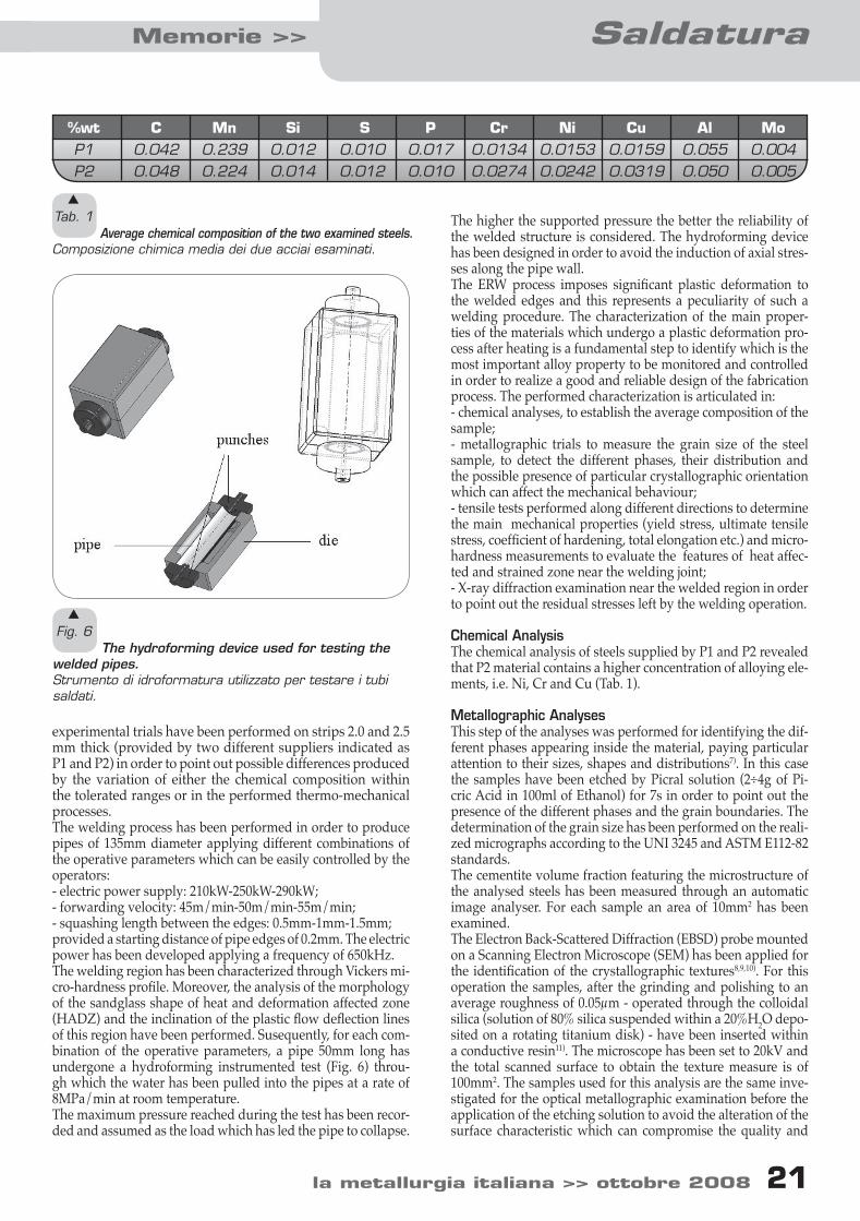
experimental trials have been performed on strips 2.0 and 2.5 mm thick (provided by two different suppliers indicated as P1 and P2) in order to point out possible differences produced by the variation of either the chemical composition within the tolerated ranges or in the performed thermo-mechanical processes. The welding process has been performed in order to produce pipes of 135mm diameter applying different combinations of the operative parameters which can be easily controlled by the operators:- electric power supply: 210kW-250kW-290kW;- forwarding velocity: 45m/min-50m/min-55m/min;- squashing length between the edges: 0.5mm-1mm-1.5mm;provided a starting distance of pipe edges of 0.2mm. The electric power has been developed applying a frequency of 650kHz. The welding region has been characterized through Vickers mi-cro-hardness profile. Moreover, the analysis of the morphology of the sandglass shape of heat and deformation affected zone (HADZ) and the inclination of the plastic flow deflection lines of this region have been performed. Susequently, for each com-bination of the operative parameters, a pipe 50mm long has undergone a hydroforming instrumented test (Fig. 6) throu-gh which the water has been pulled into the pipes at a rate of 8MPa/min at room temperature.The maximum pressure reached during the test has been recor-ded and assumed as the load which has led the pipe to collapse.
The higher the supported pressure the better the reliability of the welded structure is considered. The hydroforming device has been designed in order to avoid the induction of axial stres-ses along the pipe wall. The ERW process imposes significant plastic deformation to the welded edges and this represents a peculiarity of such a welding procedure. The characterization of the main proper-ties of the materials which undergo a plastic deformation pro-cess after heating is a fundamental step to identify which is the most important alloy property to be monitored and controlled in order to realize a good and reliable design of the fabrication process. The performed characterization is articulated in:- chemical analyses, to establish the average composition of the sample;- metallographic trials to measure the grain size of the steel sample, to detect the different phases, their distribution and the possible presence of particular crystallographic orientation which can affect the mechanical behaviour;- tensile tests performed along different directions to determine the main mechanical properties (yield stress, ultimate tensile stress, coefficient of hardening, total elongation etc.) and micro-hardness measurements to evaluate the features of heat affec-ted and strained zone near the welding joint;- X-ray diffraction examination near the welded region in order to point out the residual stresses left by the welding operation.
Chemical AnalysisThe chemical analysis of steels supplied by P1 and P2 revealed that P2 material contains a higher concentration of alloying ele-ments, i.e. Ni, Cr and Cu (Tab. 1).
Metallographic AnalysesThis step of the analyses was performed for identifying the dif-ferent phases appearing inside the material, paying particular attention to their sizes, shapes and distributions7). In this case the samples have been etched by Picral solution (2÷4g of Pi-cric Acid in 100ml of Ethanol) for 7s in order to point out the presence of the different phases and the grain boundaries. The determination of the grain size has been performed on the reali-zed micrographs according to the UNI 3245 and ASTM E112-82 standards. The cementite volume fraction featuring the microstructure of the analysed steels has been measured through an automatic image analyser. For each sample an area of 10mm2 has been examined. The Electron Back-Scattered Diffraction (EBSD) probe mounted on a Scanning Electron Microscope (SEM) has been applied for the identification of the crystallographic textures8,9,10). For this operation the samples, after the grinding and polishing to an average roughness of 0.05μm - operated through the colloidal silica (solution of 80% silica suspended within a 20%H2O depo-sited on a rotating titanium disk) - have been inserted within a conductive resin11). The microscope has been set to 20kV and the total scanned surface to obtain the texture measure is of 100mm2. The samples used for this analysis are the same inve-stigated for the optical metallographic examination before the application of the etching solution to avoid the alteration of the surface characteristic which can compromise the quality and
%wtP1P2
C0.0420.048
Mn0.2390.224
Si0.0120.014
S0.0100.012
P0.0170.010
Cr0.01340.0274
Ni0.01530.0242
Cu0.01590.0319
Al 0.0550.050
Mo 0.0040.005
s
Tab. 1 Average chemical composition of the two examined steels.
Composizione chimica media dei due acciai esaminati.
s
Fig. 6 The hydroforming device used for testing the
welded pipes.Strumento di idroformatura utilizzato per testare i tubi saldati.
19-27 mapelli.indd 21 13-10-2008 10:58:30
Saldatura << Memorie
22 ottobre 2008 << la metallurgia italiana la metallurgia italiana >> ottobre 2008 23
22 ottobre 2008 << la metallurgia italiana la metallurgia italiana >> ottobre 2008 23
the reliability of the results obtained through EBSD technique. The analysis of this crystallographic aspect can be useful in or-der to determine the origin of possible differences revealed in the mechanical behaviour.
Mechanical Analyses The plates provided for welding were treated through specific thermo-mechanical processes and so they can show significant non isotropic characteristics, then the characterization of their mechanical properties has been carried out along different di-rections.The characterization was performed through tensile tests ap-plying an elongation velocity of 25mm/min according to UNI EN 10002 which allowed to measure the Young modulus, the yield and the ultimate tensile stresses, the yield point elonga-tion (YPE) (the elongation at which the steel begins to flow plastically) and the hardening coefficient of the material (n) according to ASTM E646-00, which can be derived making a logarithmic linearization of the Hollomon equation12,13):
(1)
where εp represents the plastic component of the deformation.
As already anticipated, materials which undergo a rolling pro-cess show anisotropy in the mechanical behaviour, so the ten-sile specimens have been sampled along the three main charac-teristic directions rotated of 0, 45, 90° from the rolling one. For each sample two tensile specimens for each orientation have been considered. In order to obtain the average parameters which can describe this anisotropy the mechanical properties measured along the different directions have been reduced to an average synthetic form:
(2) The subscripts represent the angles of misalignment from the rolling direction. For the analysis of these parameters related to the anisotropy two samples have been tested for each direc-tion for the plate with a thickness of 2mm and for the one with a thickness of 2.5mm. In the rolled products other interesting parameters to be taken into account are the average normal anisotropy coefficient rm and the planar anisotropy Δr14,15) ac-cording to ASTM E517-00. The measurements of the aniso-tropy parameters have been performed after the application of a 10% strain.
s
Fig. 7 Maximum water pressure reached in 2.0 mm
thick pipe as a function of the squashing length and of the provider.Massima pressione raggiunta dall’acqua in un tubo di spessore 2.0mm in funzione della lunghezza di schiacciamento e del fornitore.
s
Fig. 8 Maximum water pressure reached in 2.5mm
thick pipe as a function of the squashing length and of the provider.Massima pressione raggiunta dall’acqua in un tubo di spessore 2.5mm in funzione della lunghezza di schiacciamento e del fornitore.
19-27 mapelli.indd 22 13-10-2008 10:58:31
22 ottobre 2008 << la metallurgia italiana la metallurgia italiana >> ottobre 2008 23
SaldaturaMemorie >>
22 ottobre 2008 << la metallurgia italiana la metallurgia italiana >> ottobre 2008 23
The presence of a possible Heat Affected Deformed Zone (HADZ) has been evaluated through the determination of Vi-ckers micro-hardnesses (ASTM E384) across the welded joint, in which the measurements have been performed with a step of 50μm between two successive measurements and applying a load of 25g for 15s.
Determination of the residual stressesUsing an X-Ray diffractometer (X-Stress 3000) and varying the work angle between -45° and +45°, the measurement of the residual stresses inside the material has been performed: the diffractometer provides the values of the two stresses σ1 and σ2 and the amplitude of the angle φ, representing the ro-tation between the stresses measured along the fixed reference system and the direction of the principal stresses(σ,τ). These quantities can be opportunely elaborated to give the value of the Von Mises equivalent stress: (3)where
(4)
(5)
RESULTS AND DISCUSSION
The highest resistance level to the hydroforming pressu-re has been reached for 1mm pulling length and this im-plies (provided an initial edge distance of 0.2mm) that the squashing penetration between the pulled edges is of 0.8mm (Fig. 7, Fig. 8, Fig. 9). This distance seems funda-mental to grant a correct symmetry of the sandglass shape of HADZ and the average deflection angle of 35.1° (st.dev. ±3.1°) at the middle of thickness and of 78.3° (st.dev. ±2.9°) near the surface in order to assure an efficient removal of the defects produced by the presence of oxides or dirty residuals (Fig. 10, Fig. 11). At the same time the largest
s
Fig. 9 Morphology of the welded zone in 2.5mm thick
pipes with steel provided by P1.Morfologia della zona saldata in un tubo di spessore 2.5mm fornito da P1.
s
Fig. 10 Example of the revealed deflection lines
of plastic flow revealed on a welding performed through the correct combination of the technological parameters.Esempio delle linee di deflessione associate al flusso plastico rivelate su una saldatura effettuata con il settaggio ottimale dei parametri tecnologici.
s
Fig. 11 Example of dirty materials and oxides pulled out
from the welded joining by the squashing movement.Esempio dello sporco e degli ossidi estratti dal giunto saldato durante il movimento di squashing.
19-27 mapelli.indd 23 13-10-2008 10:58:31
Saldatura << Memorie
24 ottobre 2008 << la metallurgia italiana la metallurgia italiana >> ottobre 2008 25
24 ottobre 2008 << la metallurgia italiana la metallurgia italiana >> ottobre 2008 25
squashing (1.5mm) seems to cause an excessive distor-tion of the sandglass shape which is always associated to unacceptable damage of the seam or of the adjacent region (Fig. 9).The lowest value of the squashing length does not grant the complete expulsion of the defects and this is proved by the values assumed by the deflection angle of 23.1° (st.dev. ±4.3°) at the middle of thickness and 47.1° (st.dev. ±5.1°), near the surface, which does not seem enough to assure the removal of the defect and a strong and reliable welded junction (Fig. 9, Fig. 12). Once identified the most favourable squashing length, it is possible to search the correct combination of electric po-wer supply and forwarding velocity. The more promising combinations seem to be:- 210kW for 45m/min;- 250kW for 50m/min;- 290kW for 55m/min.This indicates that the specific energy for unit length to be welded is included between 280kJ/m and 316kJ/m.On the other hand, difference shown by the steels produ-ced by different providers demonstrate that the correct in-dividuation of the technological parameters is not enough for maximizing the mechanical performances of the wel-ded pipes. Actually, the pipes produced using the steel provided by P2 show systematically worse performances than the ones provided by P1. Thus, micro-structural inve-stigations can cast a further light to assure a better quality level.The surface developments of the cracks are always parallel to the welding seam (Fig. 4, Fig. 13). The P1 steel shows slightly coarser grains than P2 one and so these steels present different values of the grain size ASTM coefficient (9 and 10, respectively) (Fig. 14).The amount of cementite (Fe3C) precipitated on the grain boundaries in P2 steels is of 31% greater than the one fe-aturing the P1 microstructure (Fig. 15); this precipitation allows the enhancement of the hardness of the material but causes, at the same time, increase in the brittleness and a loss in the plastic formability of the steel (Tab. 2).The texture analysis16,17,18,19) points out the presence of com-
s
Fig. 12 Examples of defects trapped within the
welding and the absence of regular continuity within the joining associated with the lowest level of squashing.Esempio dei difetti intrappolati all’interno della saldatura e dell’assenza della regolare continuità in corrispondenza delle giunzioni associate ai livelli più bassi di squashing (schiacciamento).
s
Fig. 13 Example of a fracture developed on the welded
pipe.Esempio di una frattura sviluppatasi sul giunto saldato.
s
Fig. 14 Example of the grains featuring two steels
provided by P1 and P2.Esempio della microstruttura caratteristica dei due acciai forniti da P1 and P2.
s
Fig. 15 Example of the characteristic difference in the
features of the cementite precipitates present in steels provided by P1 and P2. In the P1 steel the cementite precipitates are less and less coarse than in P2 steel.Esempio delle tipiche differenze nelle caratteristiche della cementite precipitata negli acciai forniti da P1 and P2: nell’acciaio P1 i precipitati sono inferiori in numero e meno grossolani rispetto all’acciaio P2.
19-27 mapelli.indd 24 13-10-2008 10:58:31
24 ottobre 2008 << la metallurgia italiana la metallurgia italiana >> ottobre 2008 25
SaldaturaMemorie >>
24 ottobre 2008 << la metallurgia italiana la metallurgia italiana >> ottobre 2008 25
ponents particularly suitable for a plastic deformation pro-cess, actually a prominence of the components in γ-fibre in all the samples under examination has been revealed; the only difference is the greater dispersion of components featuring the P2 samples, joined together with a lower in-tensity of favourable textures characterized by the planes {111} and {110} of the body centred cubic lattice lying pa-rallel to the rolling plane (Fig. 16, Fig. 17). Moreover, P2 steel shows a more intense {001}<100> Cube component which is usually detrimental for the formability attitude. Thus, this situation can cause a worse formability attitude, which seems to produce considerable variation on the har-dening coefficient. The tensile tests carried out indicated that P2 steels are fea-tured by higher values of Young modulus and yield stress, if compared to the values typical of P1 materials (Tab. 2).On the contrary, P1 steels present yield point elongations slightly higher than P2 ones, even if the values are very close and correspond to few percents. The presence of si-gnificant yield point elongation is a peculiarity of the low carbon steels and it can represent a ductility parameter of the material, although an excessive value of this parameter may cause the appearance of the so called ‘Lüders bands’ on the surface and on the layer immediately under it. This phenomenon can be detrimental for the surface quality of the component, but in this case the performed industrial trials have not revealed this problem.The average normal anisotropy parameter (rm) and the one describing the planar anisotropy (Δr) turned out to be practically similar in all the analysed samples and the dif-ference pointed out cannot be the responsible for the for-mation of the micro-cracks developed in P2 steel.On the contrary, the hardening coefficient and the yield elongation point assume significantly higher values in the steels provided by P1 than in the ones from P2. Thus, this parameter seems to cover an important role in order to avoid the start up and the development of the cracks
P1 2mm P1 2.5mmP2 2mm
P2 2.5mm
E(GPa)
205189202207
Yield stress (MPa)300275303325
Yield point of elongation (%)
44.53.63
rm
0.910.940.930.93
Δr
-0.09-0.13-0.1
-0.18
n
0.220.2
0.150.14
s
Tab. 2 Main average mechanical characteristics revealed by
the tensile tests.Valori medi delle principali caratteristiche meccaniche misurate mediante prove di trazione.
s
Fig. 16 Main textures pointed out by the ODF diagram
section on correspondence of (a)ϕ2=0° and (b)ϕ2=45°at the middle of the thickness in steel 2.5mm thick provided by P1.Principali tessiture emerse dalla sezione del diagramma ODF in corrispondenza di (a)ϕ2=0° e (b)ϕ2=45° a metà profondità in un acciaio dello spessore di 2.5mm fornito da P1.
s
Fig. 17 Main textures pointed out by the ODF diagram
section on correspondence of (a)ϕ2=0° and (b)ϕ2=45° at the middle of the thickness in steel 2.5mm thick provided by P2.Principali tessiture emerse dalla sezione del diagramma ODF in corrispondenza di (a)ϕ2=0° e (b)ϕ2=45° a metà profondità in un acciaio dello spessore di 2.5mm fornito da P2.
s
Fig. 18 Example of the comparison of the average
measured micro-hardness profile in the steel provided by P1 and P2.Esempio del confronto dei profili medi di microdurezza negli acciai forniti da P1 e P2.
19-27 mapelli.indd 25 13-10-2008 10:58:31
Saldatura << Memorie
26 ottobre 2008 << la metallurgia italiana la metallurgia italiana >> ottobre 2008 27
26 ottobre 2008 << la metallurgia italiana la metallurgia italiana >> ottobre 2008 27
near the welding seam. The Vickers micro-hardness pro-file measured on the welding reveals a hardness of about 220-240HV and a slightly higher value in the region just adjacent the seam and more pronounced in the steel pro-vided by P2, probably due also to a larger carbide precipi-tation (Fig. 18). The value of hardness measured in HADZ are extremely high if compared to the base material ones featured by average values included between 120-140HV. Provided that the melted and solidified region is averagely around 40μm, the increase to around 220-240HV revealed for about 200μm on the two sides of the seam appears to be largely caused not only by heating but also by the harde-ning process due to the performed plastic straining.The analyses realized using the X-Ray diffractometer con-firmed this statement, revealing that P1 steels show average higher residual stresses, if compared to welded steels provi-ded by P2 [233MPa (P1) vs. 118MPa (P2)] (Tab. 3). The most plausible explanation of this phenomenon could be the par-tial relax of the stresses produced by the formation even of micro-cracks in the region adjacent the welding seam.Thus, the results of the performed analysis pointed out that the significant difference are related to:- the chemical composition of the steel;- the amount of the cementite precipitation on the grain boundaries;- the values assumed by the hardening coefficient;- the relaxation residual stresses produced by the welding system.These aspects can play a cooperative role in the produc-tion of the revealed damage of the welded structure. The most reliable explanation of the failure process can be sum-marized in this way: when the compression produced by the rolls between the sides to be welded is removed, the welded pipe undergoes a displacement due to the elastic return which produces a stress on the welded seam and on the adjacent regions. These residual stresses produce some strains in the steels which are higher when the hardening coefficient is lower. Actually, a high hardening coefficient contains the deformation produced by the residual stresses. If the hardening coefficient is low enough to cause a defor-mation which is over the maximum local strain acceptable
by the material, this gives rise to the cracks. The formation of cracks relaxes the induced residual stress and this can explain the lowest values found in the cracked steels. On the other hand, the chemical composition and the related cementite precipitation seem to play an important role too, because the presence of elements which increase the car-bide formation, i.e. chromium, increases the hardness and decreases the ductility of steel which is more sensitive to the cracks induced by the strain caused by the welding stresses. Thus, a high yield point of elongation, a high har-dening coefficient and a chemical composition not prone to the carbide precipitation seem to be the most important parameters for a correct realization of the ERW process to produce tubular structure.
CONCLUSIONS
The production of pipes featured by a correct soundness throu-gh the ERW process can take advantage by the control of the technological parameters: a squashing length of 1 mm starting from a distance of 0.2 mm associated to an energy supply per unit length included in the range of 280kJ/m and 316kJ/m se-ems to represent an optimal combination. On the other hand, at least two further important aspects re-lated to the selection of the material need to be taken into ac-count. The first aspect is the choice of a steel with a contained tendency to the precipitation of carbides, because this avoid an excessive lowering of the ductility of the steels; on the other hand, this is a factor always taken into account for all the wel-ding process. A second important aspect, that can be added also to the procedure of quality control of the starting base material is granting high enough hardening index and yield elongation point, because they can decrease the plastic strain induced by the residual stresses left by the welding system wi-thin the steel structure.
REFERENCES
[1] R.K.Nichols: ‘High frequency welding, the process and the applications’, Proceeding of International Tube Confe-rence, 1999; [2] R.K.Nichols: ‘High frequency: pipe and tube welding’, Proceedings International Tube Conference, 1994;[3] P.F. Scott: ‘Key parameters of high frequency welding’, Proceedings of the Tube&Pipes Congress 1996, Dusseldorf, Germany, 1996;
1
35834-85
1236-772
2
129-30
216857
-121
3
1384831
3107802
4
25711040
411820-37
P1
P2
s
Tab. 3 Measured residual stress measured in the
region where the micro-cracks usually take place.Sforzi residui misurati nella regione dove generalmente si sviluppano le microcricche.
Average Von Mises Stress 118MPa
n° of test
sigma 1 (MPa)sigma 2 (MPa)
Phi
n° of testsigma 1 (MPa)sigma 2 (MPa)
Phi
s
Fig. 19 Example of micro-fracture revealed in steel
provided by P2 featured by a lower residual stress.Esempio di una microfrattura rivelata nell’acciaio fornito da P2 e caratterizzato da un basso livello degli sforzi residui.
19-27 mapelli.indd 26 13-10-2008 10:58:31
26 ottobre 2008 << la metallurgia italiana la metallurgia italiana >> ottobre 2008 27
SaldaturaMemorie >>
26 ottobre 2008 << la metallurgia italiana la metallurgia italiana >> ottobre 2008 27
[4] J. W. Elmer, T. A. Palmer, W. Zhang, B. Wood and T. De-bRoy: Acta Mater., 51 (2003), 3333.[5] B. H. Chang and Y. Zhou: J. Mater. Process. Technol., 139 (2003), 635.[6] A. De, L. Dorn and O. P. Gupta: Sci. Technol. Weld. Joi-ning, 5 (2000), 49;[7] Y. Watanabe and I. Momose: Ironmaking Steelmaking, 31 (2004), 265;[8] Internet site: www.ebsd.com;[9] W. B Hutchinson and M. Hatherley: An Introduction to Texture in Metals, Monograph 5, The Institution of Metal-lurgists, London, (1979), 255. [10] U. F. Kocks, C. N. Tomè and H.-R. Wenk: Texture and Anisotropy, Cambridge University Press, Cambridge, (2000), 421;[11] W. F. Hosford and R. M. Caddell: Metal Forming: Me-chanics and Metallurgy, 2nd Ed., PTR Prentice Hall, New York, (1993), 286 [12] R. K. Ray, J. J. Jonas and R. E. Hook: Int. Mater. Rev., 39 (1994), 129;[13] Standard UNI EN 10002, ‘Materiali metallici: prova di trazione a temperatura ambiente’ (1992);[14] Standard ASTM E517-00: ‘Standard test method for pla-stic strain ratio for sheet metal’ (August 2000);[15] W. T. Lankford, S. C. Snyder and J. A. Bauscher: Trans. Am. Soc. Met., 42 (1950), 1197. [16] M. R. Barnett: Modern LC and ULC Sheets Steels for Cold Forming: Processing and Properties, ed. by W. Bleck,
Aachen University of Technology, Aachen, (1998), 61;[17] M. R. Barnett and J. J. Jonas: ISIJ Int., 39 (1999), 856;[18] H. J. Bunge: Texture Analysis in Materials Science-Ma-thematical Methods, Butterworths, London, (1982), 145;[19] U. F. Kocks, C. N. Tomè and H.-R. Wenk: Texture and Anisotropy, Cambridge University Press, Cambridge, (2000), 421.
LIST OF SYMBOLS
E Young modulus [GPa]rm average normal anisotropy coefficientΔr planar anisotropy coefficientK coefficient of strengthening in the Hollomon relation [MPa]n hardening coefficientσV.M. Von Mises Equivalent Stress [MPa]εw width deformationεt thickness deformationεp plastic component of the deformationl0 initial length of the specimen used for the tensile test [m] lf final length of the specimen used for the tensile test [m]r normal anisotropy coefficientrm average normal anisotropy coefficientXm average value of the generic mechanical parameter XXn value of the generic mechanical parameter X along a
direction rotated by n from the rolling directionw0 initial width of the specimen used for the tensile test [m]wf final width of the specimen used for the tensile test [m]
ABSTRACTRICERCA DEI PARAMETRI TECNOLOGICI E METALLURGICI OTTIMALI PER L’ESECUZIONE DELLA SALDATURA PER RESISTENZA ELETTRICA DEGLI ACCIAI A BASSO CARBONIO
Parole chiave: saldatura per resistenza elettrica, preci-pitazione della cementite, coefficiente di incrudimento, deformazione allo snervamento, sforzi residui
Il presente lavoro tratta la ricerca dei parametri tecnologici e metallurgici ottimali per implementare un processo affidabile di saldatura elettrica per resistenza degli acciai strutturali a basso tenore di carbonio (Tabella 1) e per stabilire le condizioni in grado di garantire le migliori prestazioni dal punto di vista meccanico. Gli acciai in esame devono possedere elevate capacità di deformazione plastica in quanto il processo produttivo prevede l’avvolgimento di un nastro laminato, seguito dalla saldatura delle estre-mità per resistenza elettrica (ERW – Electric Resistance Welding) (Figure 1 e 2). I parametri tecnologici ottimali sono stati evidenziati mediante
l’esecuzione di test di saldatura a diversi livelli di potenza elettrica, lun-ghezza di schiacciamento e velocità di avanzamento del tubo lungo gli assi delle bobine. Per la misura delle proprietà del materiale considerato sono stati eseguiti diversi test meccanici allo scopo di caratterizzare le principa-li proprietà meccaniche, quali il modulo di Young, i carichi di snervamen-to e di rottura, l’allungamento al punto di snervamento (lo sforzo oltre il quale comincia il comportamento plastico), i coefficienti di anisotropia (rm, Δr), le microdurezze Vickers e i coefficienti di incrudimento (Tabella 2); gli sforzi residui indotti in corrispondenza dei giunti saldati sono stati determinati per mezzo della diffrazione di raggi X (Tabella 3). Le caratte-ristiche microstrutturali degli acciai sono state ottenute attraverso analisi micrografiche accoppiate all’utilizzo di tecniche di diffrazione EBSD (dif-frazione degli elettroni retrodiffusi) (Figure 16 e 17). Si è riscontrato che i valori dei coefficienti di incrudimento e dei punti di yield elongation sono da ritenersi un parametro particolarmente significativo per assicurare la qualità della saldatura ed evitare la prematura formazione di cricche in prossimità dei giunti saldati (Figure 13 e 19) a seguito delle operazioni di compressione o espansione sulle superfici laterali dei tubi.
19-27 mapelli.indd 27 13-10-2008 10:58:32
CorrosioneMemorie >>
29 ottobre 2008 << la metallurgia italiana la metallurgia italiana >> ottobre 2008 29
CORROSION AND PROTECTION OF FRICTION STIR WELDS IN AEROSPACE
ALUMINIUM ALLOYS C. G. Padovani, A. J. Davenport, B. J. Connolly, S. W. Williams,
A. Groso, M. Stampanoni, F. Bellucci
Keywords: aluminium alloys, welding, corrosion
INTRODUCTION
Friction stir welding [1] (FSW) offers the opportunity of obtain-ing high quality welds in the traditionally poorly weldable high strength aluminium alloys of the 2XXX and 7XXX series. Due to the excellent quality of the welded joints, aircraft manufactures are considering the introduction of this technology in aircraft components. Friction stir welding has been used with success in joining primary structures in the Eclipse 500™ jet [2], and will be applied to join external fuel tanks in the NASA Space Shuttle [3]. A review of recent investigations on the properties of FSW has been compiled by Mishra and Ma. [4]. The corrosion performance of the welds has been analysed in a number of studies, which show that the thermal cycle produced by welding leads to significant changes in the microstructure of the metal, leading to enhanced corrosion susceptibility [5-24]. In aerospace alloys of the 2XXX and 7XXX series, this causes con-cerns related to the corrosion-fatigue of FSW components, as the onset of localised corrosion in aluminium alloys is known to be able to decrease this parameter (e.g. [25]). Recent work on AA2024 T351 [16, 17] showed the correlation between welding parameters and precipitation of the age-S phase, while for 7XXX
C. G. Padovani, A. J. Davenport, B. J. ConnollyUniversity of Birmingham, Metallurgy and Materials, Birmingham (UK)
S. W. WilliamsCranfield University, Welding Engineering Research Centre, Cranfield (UK)
A. Groso, M. StampanoniSwiss Light Source, Paul Scherrer Institut, Villigen PSI, (Switzerland)
F. BellucciUniversità degli studi di Napoli Federico II, Dipartimento di Ingegneria
dei Materiali, Napoli (Italia)
alloys changes in electrochemical behaviour have been attributed to the precipitation of η phase.Due to the sensitisation of the weld region, it may be desirable to improve the corrosion performance of friction stir welds by the use of appropriate post treatments. The use of post weld heat treatments to increase and homogenise the corrosion resistance of the weld had limited success [22, 26-30] and tend to be restricted by physical limitations related to the size of the components to be treated.Laser surface melting is able to increase the corrosion resistance of aluminium by dissolving the detrimental constituent particles present in commercial alloys [31] and can be considered for the treatment of FSW due to its ability of forming, in appropriate conditions, corrosion resistant, precipitate free layers. This has been obtained with Excimer lasers [32-39], in which the short du-ration of the thermal cycle induced by laser irradiation leads to limited microsegregation in the molten and resolidified layer. The use of laser surface melting to increase the corrosion resist-ance of friction stir welds has been recently investigated [5, 6, 10, 11, 40, 41]. Apart from increasing the corrosion resistance of the parent material and of the weld region, the use of laser surface melting to increase the corrosion resistance of welds might offer
AA2024AA7449
Si0.500.12
Fe0.500.15
Cu3.8-4.91.4-2.1
Mn0.3-0.90.20
Mg1.2-1.81.8-2.7
Cr0.10
-
Zn0.25
7.5-8.7
Ti + Zr 0.150.25
Al balbal
s
Tab. 1 Nominal chemical composition of AA2024 and AA7449.
Composizione chimica nominale delle leghe AA2024 and AA7449.
the ulterior benefit of reducing galvanic coupling effects between different weld regions that can occur if wetting of the metal with a relatively conductive electrolyte takes place. This paper discuss the application of laser treatment with Excimer laser to increase the corrosion resistance of friction stir welds in AA2024-T351 and AA7449 T7951.
EXPERIMENTAL METHOD
AA2024-T351 and AA7449-T7951 laser surface melted friction stir welds were supplied by BAE SYSTEMS in the form of 4.0 mm and 12.2 mm thick plates respectively; the nominal chemical com-position of the alloys is reported in Tab. 1. Friction stir welding was performed with a Triflute™ carbon steel tool piece at rotation
29-42 padovani.indd 29 13-10-2008 11:18:47
Corrosione << Memorie
30 ottobre 2008 << la metallurgia italiana la metallurgia italiana >> ottobre 2008 31
30 ottobre 2008 << la metallurgia italiana la metallurgia italiana >> ottobre 2008 31
speed of 486 rpm and a traverse speed of 195 mm min 1. Me-chanical milling of few mm from the weld surface was performed before laser-treating the welds to remove the characteristic weld “crown”.Laser surface melting was performed in BAE SYSTEMS with a XeCl Excimer laser (wavelength λ = 308 nm) on the surface of FSW plates (L-LT plane). The laser was operated at a fluence of 10 J cm-2 in a 3x3 raster scanning mode in order to obtain 9 pulses per unit area and hence an integrated fluence of 90 J cm2. The laser treatment was performed in air after organic degreasing of the plates with iso propanol. Appropriate degreasing was found to be important as external species (for example from the lubricant used during previous rolling operations) were found to be poten-tially incorporated in the treated layer if not adequately removed. The laser focusing system comprised of micro-array of lenses that produced a spot size of 1.5 mm x 1.5 mm.The morphology of laser-treated FSW was characterised with SEM microscopy of surface and cross section. The cross sections were prepared via cutting with a Struers “Accutom 5” precision machine, cold mounting in a Met Prep “Tri-Hard” epoxy resin and polishing to 1 μm with Struers “DiaDuo” diamond suspen-sion. Before examination, a thin carbon coating was deposited on the sample in order to eliminate charging effects at the metal/resin interface and make it electrically conductive. For this analy-sis a JEOL 7000F FEG-SEM was used in secondary electron and backscattering mode at an accelerating voltage of 15 kV. Chemical analysis of the laser treated material was also carried out using Energy Dispersive X-ray Spectroscopy (EDX), performed at an accelerating voltage of 15 kV with a JEOL 6400 SEM equipped with a Noran Instruments EDX detector.The electrochemical reactivity of laser-treated and untreated welds was tested in a 0.1 M NaCl solution in a micro-capillary cell. In this setup a droplet of solution of controlled dimensions is positioned via a pipette tip on the area to be tested. The pipette is physically connected to a solution reservoir where both reference electrode (Ag/AgCl) and counter electrode (platinum wire) are accommodated. Details on the use of this technique are reported elsewhere [5, 6, 16, 17]. For all the tests performed in this work, a pipette tip with a contact area of 1.2 mm2 was used. Anodic and cathodic polarisation tests were performed on selected areas of la-ser treated and untreated welds; the tests were performed on the weld surface in a scan perpendicular to the welding direction in order to obtain a map of the electrochemical reactivity as a func-tion of position across the weld line. Anodic and cathodic scans were performed separately on different spots after 300 seconds of free corrosion in which the open circuit potential (OCP) was monitored. The scan started at the OCP (± 10 mV) and proceeded to higher (anodic polarisation) and lower (cathodic polarisation) values of the potential. Only the cathodic polarisation measure-ments performed on the laser treated AA2024-T351 started from a value of the potential different from the OCP, which was -800 mV vs. Ag/AgCl. The sweep rate was 1 mV s-1. The surface preparation involved polishing to 1 μm 3 days before testing for untreated welds and 30 seconds immersion in concentrated ni-tric acid immediately before testing for the laser treated welds. Just before testing, untreated and laser treated weld samples were rinsed with deionised water, ethanol and air dried. Nitric acid dipping was adopted as preparation procedure for the laser treated material since the normal grinding/polishing preparation procedure would have removed the laser treated layer. The fact that untreated and laser treated surfaces were pre-treated, before the electrochemical tests, in different manners did not affect the interpretation of the results (not shown). Immersion tests in Cl-containing electrolyte were performed to
verify whether the presence of laser treatment on the alloys would reduce the severity of corrosion and to understand whether the presence of scratches in the treatment would be accompanied by significant corrosion of the substrate. Samples about 1 cm wide and 8 cm long (for an overall area of 8 cm2) were scratched and immersed in corrosive electrolyte. The immersion was carried out in two independent tests for 5 and 20 days in a naturally aerated 0.1 M NaCl solution on untreated and laser treated welds. The samples were covered in several layers of “Stopping off” lacquer to expose only the L-LT surface. The immersion was performed in a beaker immersed in a thermal bath at a temperature of 25°C; deionised water was periodically added to the system in order to keep the solution volume and the electrolyte concentration con-stant with time. The samples were scratched across the weld re-gion perpendicular to the welding direction. Both untreated and laser treated welds were scratched for consistency. The scratch was produced few days before immersion in the electrolyte with a sharp stainless steel tool and was estimated to be ~ 10-15 μm deep after profilometric analysis. As the depth of the LSM layer was only 3 5 μm thick, the scratch was deep enough to expose the substrate. On the corroded samples, 2D analysis was performed via optical and SEM microscopy of surface and cross section and 3D analysis was performed with X ray microtomography (ex situ samples). Before examination, removal of corrosion products was carried out in some cases with immersion for 2 minutes in con-centrated nitric acid.Open circuit potential (OCP) measurements were also performed on untreated, intact laser-treated and scratched laser treated samples to evaluate the effects of galvanic coupling between la-ser treated layer and scratched area (substrate). The dimension of these samples was about 9 cm2, similar to that of scratched weld samples. This ensured similar anode/cathode ratio in both experiments. The tests were performed for 24 hours in naturally aerated 0.1 M NaCl in a beaker containing 500 ml of solution. The data acquisition rate was set to 1 measurement every 100 seconds. The samples were covered with several layers of “Stopping off” lacquer in order to expose only the scratched L-LT surface (laser treated or untreated). For these measurements, the reference elec-trode was a Saturated Calomel Electrode (SCE). The temperature was controlled at values of 25°C with a water bath. X ray microtomography was performed at the Materials Science beamline of the Swiss Light Source at the Paul Scherrer Institut in Switzerland [43]. This technique represents a powerful tool to image the microstructure of relatively small volumes of material in 3 dimensions and was used to understand the mechanism of corrosion propagation in laser treated material. The acquisition apparatus comprised a 28 μm thick Ce-doped YAG scintillator. The beam energy was set to 17.5 keV, the exposure time to 2 sec-onds. 721 radiographs were acquired in a complete 180° rotation around the sample axis at regular angles of ~ 0.25 degrees. The acquisition window of the camera was set to 1024 x 1024 pixels in 2x ‘binning mode’, resulting in a theoretical pixel size of ~ 1.4 μm. The 3D information was reconstructed with traditional filtered (Butterworth) backprojection algorithm. Sample ‘pins’ (parallel-epipeds with base dimension of about 700 μm x 700 μm) were cut with a Struers “Accutom-5” machine and glued with “Araldite” glue in stainless steel holders. Ex situ samples were cut out from nugget, HAZ and parent material of laser treated welds after immersion test, as described in the previous paragraphs. These samples were analysed in order to investigate corrosion propa-gation in damaged LSM layers. Samples for in situ experiments were cut from nugget, HAZ and parent material of laser-treated welds and exposed in situ to a 0.1 M NaCl solution in a radiation transparent silicone rubber tube. In this case, the cut surfaces of
29-42 padovani.indd 30 13-10-2008 11:18:48
30 ottobre 2008 << la metallurgia italiana la metallurgia italiana >> ottobre 2008 31
CorrosioneMemorie >>
30 ottobre 2008 << la metallurgia italiana la metallurgia italiana >> ottobre 2008 31
s
Fig. 1 Excimer laser treated AA2024-T351 FSW; (a)
and (b) optical micrographs showing surface morpho-logy after the treatment; (c) and (d) SEM micrographs (secondary electron mode) showing absence of precipi-tation on the treated surface.Saldatura FSW in lega 2024-T351 dopo trattamento con Excimer laser; (a) e (b) micrografie che mostrano la morfologia della superficie dopo il trattamento; (c) e (d) micrografie SEM (secondary electron mode) che mostra-no l’assenza di precipitati sulla superficie trattata.
the sample were exposed to the corrosive solution in addition to the laser treated surface. The samples were glued to the stainless steel holders with a continuous layer of glue in order to prevent the simultaneous exposure to the electrolyte of aluminium and stainless steel which would have resulted in undesired galvanic coupling effects. On each in situ sample, analysis before and dur-ing immersion (after 24 hours) was carried out. These samples were analysed to investigate the mechanism of corrosion propa-gation in laser treated layers.
EXPERIMENTAL RESULTS
Laser-treated layer morphologyFig. 1a shows an optical micrograph of a AA2024 T351 laser treated friction stir weld; the characteristic pattern produced
s
Fig. 2 Cross section SEM micrographs (backscattered
electron mode) showing melted constituent particles in the LSM layer produced on (a) parent material, (b) FSW HAZ and, (c) FSW nugget on AA2024-T351 laser treated FSW.Micrografie SEM della sezione trasversale (backscattered electron mode) che mostrano la dissoluzione delle parti-celle costituenti nello strato LSM su (a) parent material, (b) FSW HAZ e, (c) FSW nugget su saldature FSW in lega AA2024-T351.
s
Fig. 3 EDX elemental analysis of untreated and laser
treated parent material; (a) AA2024 T351; (b) AA-449-T7951. The laser treated material shows slight enrichment in Cu (a) and Cu and Zn (b) relative to the untreated material. The nominal chemical composition of the alloys is also plotted.Analisi EDX su parent material trattato laser e non trat-tato; (a) lega AA2024-T351; (b) lega AA7449 T7951. Il materiale trattato laser mostra arricchimento in Cu (a) e Cu e Zn (b) della superficie rispetto al materiale non trattato. La composizione chimica nominale delle leghe è anche riportata.
a
b
on the metal surface after the LSM treatment is visible from the magnified view displayed in Fig. 1b. Higher magnification SEM micrographs of the treated surface show the absence of the characteristic micron-sized constituent particles found in AA2024-T351 (Figs. 1c and 1d). SEM micrographs of the cross section of the same sample show dissolution of the bright, micron-sized constituent particles and formation of a 3 5 μm thick precipitate-free layer in any weld region (Fig. 2). Similar morphology was found for the AA7449-T7951 (not shown), although less contrast elemental between LSM layer and sub-strate was visible in this case in the SEM backscattered im-ages.Fig. 3 shows the elemental composition of the LSM layer ob-
29-42 padovani.indd 31 13-10-2008 11:18:48
Corrosione << Memorie
32 ottobre 2008 << la metallurgia italiana la metallurgia italiana >> ottobre 2008 33
32 ottobre 2008 << la metallurgia italiana la metallurgia italiana >> ottobre 2008 33
tained on AA2024-T351 (a) and AA7449-T7951 (b). For both alloys, the results show that the LSM layer and the matrix ex-hibit similar elemental composition, with some enrichment in Cu (AA2024) and Cu and Zn (AA7449) in the LSM layer.
Electrochemical characterisation of laser-treated weldsThe electrochemical reactivity of the LSM layers was tested with anodic and cathodic polarisation tests performed with mi-cro capillary cell. Anodic polarisation curves and breakdown potentials obtained on laser treated and untreated welds in both alloys are shown in Fig.4. The graphs show typical anodic polarisation curves for parent untreated and LSM material and the breakdown potential across the weld region, evaluated as the potential in which the value of the anodic current density reaches 2 10-5 A cm-2.
Despite the scatter in the values of the breakdown potential, the separation between the curves measured on untreated and laser treated welds (Fig. 4a and 4b) demonstrates that, for AA2024-T351, the laser treatment confers an improvement in corrosion resistance, as the breakdown potential is signifi-cantly increased after the laser treatment. Furthermore the breakdown potential is fairly consistent across the entire weld for the laser treated surfaces, but is lower in the weld region for the untreated weld, showing the greatest susceptibility to anodic dissolution of this region if no post weld treatment is carried out.Different results were found for the AA7449-T7951 (Fig. 4c and 4d), in which anodic polarisation curves and breakdown potentials measured on untreated and laser treated FSW were similar. The values of the breakdown potential on the LSM
s
Fig. 4 Anodic reactivity of laser treated and untreated FSWs in 0.1 M NaCl. (a) and (b) AA2024-T351; (c) and (d)
AA7449-T7951. (a) and (c) Are typical anodic polarisation curves in parent material comparing the reactivity of the laser treatment with the reactivity of the untreated metal; (b) and (d) Are nominal breakdown potentials (Eb) at i = 2 x 10⁻⁵ A cm2 as a function of position relative to the weld centre for laser treated (dipped in nitric acid) and untrea-ted FSW (polished). A = ‘advancing’ side of the weld; R = ‘retreating’ side of the weld.Caratteristica anodica di saldature FSW dopo trattamento laser in 0.1 M NaCl. (a) e (b) Lega 2024-T351; (c) e (d) lega 7449-T7951. (a) e (c) Sono tipiche curve di polarizzazione anodica nel parent material che confrontano la reattività del trattamento laser con quella del metallo non trattato. (b) e (d) Sono i potenziali di breakdown nominale Eb valutati alla cor-rente i = 2 x 10⁻⁵ A cm2 in funzione della posizione rispetto al centro della saldatura. A = parte ‘advancing’ della saldatu-ra; R = parte ‘retreating’ della saldatura.
a b
c d
29-42 padovani.indd 32 13-10-2008 11:18:48
32 ottobre 2008 << la metallurgia italiana la metallurgia italiana >> ottobre 2008 33
CorrosioneMemorie >>
32 ottobre 2008 << la metallurgia italiana la metallurgia italiana >> ottobre 2008 33
weld were scattered and not uniform across the whole sam-ple, while that measured o the untreated weld show lower values in the weld region, indicative of enhanced susceptibil-ity to anodic attack. Cathodic polarisation curves and cathodic currents measured on laser treated and untreated welds for both alloys are shown in Fig. 5. The graphs show typical cathodic polarisation curves in parent material and the values of the cathodic current at a fixed potential of 900 mV vs. Ag/AgCl, which was used to compare the reactivity across the weld region.It is clear that the laser treatment can increase the corrosion resistance of both alloys by reducing the cathodic reactivity. The laser treated material (broken line) shows lower cathodic reactivity in the whole weld region and more uniform reactiv-ity in comparison with the untreated weld (solid line), where,
for both AA2024 and AA7449, a cathodic current density peak is observed in the weld nugget.
Optical and SEM microscopy examination after immer-sion in 0.1 M NaCl solutionTo verify whether the LSM treatment increases the corrosion resistance of FSWs and to understand whether the presence of potential scratches in the treatment would lead to signifi-cant dissolution in the scratched area, immersion for 20 days of scratched laser treated and untreated welds in 0.1 M NaCl solution was performed. Post immersion analysis was per-formed both in the scratched area and in areas ‘away’ from the scratch.Fig.6 shows the appearance of the AA2024-T351 untreated weld after 20 days immersion in 0.1 M NaCl followed by cor-
s
Fig. 5 Cathodic reactivity of laser treated and untreated FSWs in 0.1 M NaCl. (a) and (b) AA2024-T351; (c) and
(d) AA7449-T7951. (a) and (c) Are typical cathodic polarisation curves in parent material comparing the reactivity of the laser treatment with the reactivity of the untreated metal. (b) and (d) Are cathodic current densities at 900 mV vs. Ag/AgCl as a function of position relative to the weld centre for laser treated (dipped in nitric acid) and untrea-ted FSW (polished). A = ‘advancing’ side of the weld; R = ‘retreating’ side of the weld.Caratteristica catodica di saldature FSW dopo trattamento laser in 0.1 M NaCl. (a) e (b) Lega 2024-T351; (c) e (d) lega 7449-T7951. (a) e (c) Sono tipiche curve di polarizzazione catodica nel parent material che confrontano la reattività del trattamento laser con quella del metallo non trattato. (b) e (d) Sono le correnti catodiche nominali valutate al potenziale di 900 mV vs. Ag/AgCl in funzione della posizione rispetto al centro della saldatura. A = parte ‘advancing’ della saldatura; R = parte ‘retreating’ della saldatura.
a b
c d
29-42 padovani.indd 33 13-10-2008 11:18:48
Corrosione << Memorie
34 ottobre 2008 << la metallurgia italiana la metallurgia italiana >> ottobre 2008 35
34 ottobre 2008 << la metallurgia italiana la metallurgia italiana >> ottobre 2008 35
rosion product removal in concentrated nitric acid. The weld was found susceptible to pitting, with relatively small and sparse pits in nugget (Fig. 6b and 6e) and parent material (Fig. 6d and 6g) and coarser and more numerous pits in the HAZ (Fig. 6c and 6f). Particularly intense attack was found in the scratched area in the HAZ (Fig. 6c).Fig. 7 shows the appearance of the AA2024-T351 laser treated weld after the same test. Residues of not completely removed corrosion products were still visible after immersion in nitric acid in certain areas of the sample (Fig. 7a) so that optical mi-croscopy was necessary to gain a better evaluation of the ex-tent of corrosion damage. Evaluation on the damage in areas ‘away’ from the scratch (Figs. 7b-7g) and comparison with the extent of attack found on untreated welds indicated that local-ised corrosion sites of smaller dimension and fewer in number formed in the HAZ of the laser treated weld, where relatively small pits (comparable in dimension with those found in the parent region) developed in place of the coarse pits present in the HAZ of the untreated weld (Fig. 6c and 6f). The nugget of the laser treated weld was found to be particularly resistant (Fig. 7b).Analysis of the scratched area, however, revealed the presence of few relatively large pits in the exposed substrate after 20 days exposure to 0.1 M NaCl, especially in the HAZ (Fig. 8a). An independent immersion for 5 days confirmed this behav-iour (Fig. 8b) and showed that two relatively large pits devel-
oped in the HAZ in these conditions (note that Fig. 8b shows two large pits surrounded by white corrosion products in the HAZ, while the other black spots visible in the samples were not associated with pitting in an obvious way). From surface examination (Fig. 6c and 8a), the size of the pits developed in the scratched HAZ of the ‘10J 3x3’ laser treated weld were comparable in size with that found in the HAZ of the untreat-ed weld.The results of the immersion tests on untreated and laser-treat-ed FSWs in AA7449 T7951 are shown in Fig. 9, 10 and 11. Fig. 9a shows the appearance of the untreated weld after 20 days immersion. Corrosion products were removed before post im-mersion examination. Only half of the weld is shown in the micrograph: the other half appeared similar. Similarly to the AA2024 T351 FSW, the weld was found to be susceptible to pitting, with relatively small and sparse pits in nugget (Fig. 9b and 9e) and parent material (Fig. 9d and 9g) and coarser pits in the HAZ (Fig. 9c and 9f). Some 100 μm deep pits developed in the HAZ after 20 days immersion.Fig. 10a shows the appearance of the AA7449 T7951 laser treat-ed weld after the same test. Only half of the weld is shown. The reactivity of the laser treated weld was found relatively heterogeneous, with enhanced reactivity found in the HAZ. The weld nugget (Fig. 10b and 10e) and parent material (Fig. 10d and 10g) showed localised corrosion sites of compara-ble number and dimensions with those present in the same
s
Fig. 6 Untreated AA2024-T351 FSW after 20 days immersion in 0.1 M NaCl and removal of corrosion products in concentra-
ted nitric acid; (a) weld surface micrograph; (b), (c) and (d) optical micrographs of surface in nugget, HAZ and parent material re-spectively; (e), (f) and (g) optical micrographs of cross section showing typical localised corrosion sites in nugget, HAZ and parent material respectively. Note that micrograph (f) is taken a lower magnification than micrographs (e) and (g).Saldatura FSW in lega AA2024-T351 non trattata dopo immersione per 20 giorni in 0.1 M NaCl e rimozione dei prodotti di corrosione in acido nitrico concentrato; (a) micrografia della superficie; (b), (c) e (d) micrografie ottiche osservate in nugget, HAZ e parent material rispettivamente; (e), (f) e (g) micrografie ottiche della sezione trasversale che mostrano tipici attacchi corrosivi in nugget, HAZ e parent material rispettivamente. Notare che la micrografia (f) è stata acquisita a magnificazione inferiore di quelle mostrate in (e) e (g).
29-42 padovani.indd 34 13-10-2008 11:18:48
34 ottobre 2008 << la metallurgia italiana la metallurgia italiana >> ottobre 2008 35
CorrosioneMemorie >>
34 ottobre 2008 << la metallurgia italiana la metallurgia italiana >> ottobre 2008 35
regions in the untreated weld. However, laser treatment was beneficial in decreasing the reactivity of the HAZ, in which su-perficial attack (Fig. 10c and 10f) was found in place on fairly deep pits (Fig. 9c and 9f).Fig. 11 shows optical micrographs of the scratched area in different regions of the AA7449-T791 laser treated weld after 20 days immersion. Contrarily to what observed for AA2024 T351, the extent of attack in the scratched area was found to be much lower than on the laser treated surface. The number of pits in parent material (Fig. 11a) and nugget (Fig. 11c), for example, was much lower in the scratched area than on the intact LSM surface and much lower that that found on the un-treated weld.Open circuit potential measurements on AA2024-T351 and AA7449-T7951 laser treated and untreated parent material were employed to explain the behaviour of the scratched laser treated material. Measurements performed in 0.1 M NaCl on intact and scratched laser treated parent material and on un-treated parent material are shown in Fig. 12. For AA2024 T351 (Fig.12a), the measurements show higher OCP of the intact laser treated material in comparison with the untreated and scratched laser treated material. For AA7449-T7951 (Fig.12b), in contrast, the OCP of the LSM layer was lower that that
observed on intact parent material and similar to that of the scratched LSM material. Considerations on the OCP measure-ments are presented in the discussion.
X-ray microtomography examination of ex-situ samplesIn order to study corrosion propagation in damaged laser treated layers, X-ray microtomography was used to analyse ex situ samples cut out from a scratched AA7449-T7951 laser treated weld after immersion in 0.1 M NaCl for 5 days. The corrosion products were not removed before examination. Surface observation of the weld (Fig.11) had highlighted attack of the LSM surface in all weld regions but virtually no attack of the underlying substrate in the scratched area. X ray micro-tomography was used to gain a better characterisation of the corrosion damage. The observation that little attack develops in the scratched area of LSM AA7449 when exposed to NaCl is significantly strengthen by the set of micrographs displayed in Fig. 13, which show “slices” parallel to the LSM layer extract-ed form a 3D volume reconstruction of a sample cut out from the HAZ region of a LSM weld. Significant generalised attack, penetrating to a depth of about 30 μm, is visible on the surface of the sample. In contrast, no attack is visible in the scratched area of this sample.
s
Fig. 7 Laser treated AA2024-T351 FSW after 20 days immersion in 0.1 M NaCl and removal of corrosion products in concen-
trated nitric acid; (a) weld surface micrograph; (b), (c) and (d) optical micrographs of surface ‘away’ from the scratch in nugget, HAZ and parent material respectively; (e), (f) and (g) optical micrographs of cross section ‘away’ from the scratch showing typical localised corrosion sites in nugget, HAZ and parent material respectively.Saldatura FSW in lega AA2024-T351 trattata laser dopo immersione per 20 giorni in 0.1 M NaCl e rimozione dei prodotti di corrosio-ne in acido nitrico concentrato; (a) micrografia della superficie; (b), (c) e (d) micrografie ottiche della superficie in zone lontane dall’inta-glio in nugget, HAZ e parent material rispettivamente; (e), (f) e (g) micrografie ottiche della sezione trasversale in zone lontane dall’inta-glio che mostrano tipici attacchi corrosivi in nugget, HAZ e parent material rispettivamente.
29-42 padovani.indd 35 13-10-2008 11:18:49
Corrosione << Memorie
36 ottobre 2008 << la metallurgia italiana la metallurgia italiana >> ottobre 2008 37
36 ottobre 2008 << la metallurgia italiana la metallurgia italiana >> ottobre 2008 37
s
Fig. 9 Untreated AA7449-T7951 FSW after 20 days immersion in 0.1 M NaCl and removal of corrosion products in concentra-
ted nitric acid; (a) weld surface micrograph; (b), (c) and (d) optical micrographs of surface in nugget, HAZ and parent material re-spectively; (e), (f) and (g) optical micrographs of cross section showing typical localised corrosion sites in nugget, HAZ and parent material respectively. Note that micrograph (f) is taken a lower magnification than micrographs (e) and (g).Saldatura FSW in lega AA7449-T7951 non trattata dopo immersione per 20 giorni in 0.1 M NaCl e rimozione dei prodotti di corrosio-ne in acido nitrico concentrato; (a) micrografia della superficie; (b), (c) e (d) micrografie ottiche osservate in nugget, HAZ e parent ma-terial rispettivamente; (e), (f) e (g) micrografie ottiche della sezione trasversale che mostrano tipici attacchi corrosivi in nugget, HAZ e parent material rispettivamente. Notare che la micrografia (f) è stata acquisita a magnificazione inferiore di quelle mostrate in (e) e (g).
Fig. 8 Optical micrographs showing attack developed in the
scratched area of the AA2024-T351 laser treated welds after immersion in 0.1 M NaCl: (a) high magnification micrograph showing pits developed in laser treated FSW after 20 days immersion (see Fig. 7a); (b) pits developed in the HAZ of laser treated FSW after 5 days immersion. Note that the 5 days and 20 days immersion tests were performed on different samples.Micrografie ottiche che mostrano l’attacco corrosivo sviluppato nell’intaglio prodotto su saldatura AA2024-T351 trattata laser dopo immersione in 0.1 M NaCl: (a) micrografia ad alta magnifica-zione che mostra pit formati nell’intaglio dopo 20 giorni di immer-sione (vedi Fig. 7a); (b) pit formati nella HAZ del trattamento dopo 5 giorni di immersione. Notare che le immersioni di 5 e 20 giorni sono state fatte su campioni diversi.
s
X ray microtomography examination of in situ samplesDuring post immersion microscopic characterisation of the corrosion damage (e.g. Fig. 7g) some delamination of the LSM layer on both AA2024-T351 and AA7449-T7951 was observed. In situ X ray microtomography experiments were performed
29-42 padovani.indd 36 13-10-2008 11:18:49
36 ottobre 2008 << la metallurgia italiana la metallurgia italiana >> ottobre 2008 37
CorrosioneMemorie >>
36 ottobre 2008 << la metallurgia italiana la metallurgia italiana >> ottobre 2008 37
on “pins” cut from the nugget, HAZ and parent material of a laser treated weld to investigate this effect. In this case, dif-ferently from the “ex situ” samples, the cut untreated surfaces were exposed together with the laser treated surface.Fig. 14 shows X ray microtomography “slices” perpendicular to the axis of the “pin” sample acquired on LSM AA2024 T351 in situ before (Fig. 14a) and after (Fig. 14b) 24 hours exposure of a parent material sample in 0.1 M NaCl. The distribution of constituent particles clearly identifies the two slices as the same section of the sample. It is evident how delamination of the LSM layer took place during corrosion propagation in the laser treated material. The results obtained on HAZ and nugget samples, however, did not show any sign of delamina-tion after 24 hours exposure, suggesting that this phenomenon might take place only on some areas of a laser treated surface. Similar results were found on AA7449 T7951 (not shown).
DISCUSSION
Electrochemical measurements and immersion tests indicated a higher corrosion susceptibility of the weld region in com-parison with the parent material for untreated FSWs in both AA2024 T351 and AA7449-T7951. These results are in agree-
ment with the findings of other studies that highlighted the decrease in corrosion resistance often obtained in heat treat-able aluminium alloys as a consequence of friction stir welding [5-24].Laser surface melting produced the formation of a homogene-ous, 3-5 μm thick laser treated layer across weld region and parent material. Thermal dissolution of constituent particles and fine precipitates occurred in the LSM weld, leading to the formation of a precipitate free layer. The dissolution of con-stituent particles was enhanced in the nugget region (e.g. Fig. 2b), as in these area the constituent particles are fragmented into smaller pieces by the action of the FSW tool [16, 17]. The morphology of the laser treated layer observed in this study is consistent to that observed by other studies after laser surface melting aluminium alloys with Excimer lasers [32-39].Electrochemical measurements indicated that laser surface melting with an Excimer laser can improve the corrosion resist-ance of AA2024-T351 friction stir welds by decreasing cathod-ic reactivity and increasing the breakdown potential in weld region and parent material. Furthermore the electrochemical measurements showed that laser treating the weld can produce a certain homogenisation of the reactivity, with consequent re-duction of galvanic coupling effects that could occur if wetting
s
Fig. 10 Laser treated AA7449-T7951 FSW after 20 days immersion in 0.1 M NaCl and removal of corrosion products in concen-
trated nitric acid; (a) weld surface micrograph; (b), (c) and (d) optical micrographs of surface ‘away’ from the scratch in nugget, HAZ and parent material respectively; (e), (f) and (g) optical micrographs of cross section ‘away’ from the scratch showing typical localised corrosion sites in nugget, HAZ and parent material respectively.Saldatura FSW in lega AA7449-T7951 trattata laser dopo immersione per 20 giorni in 0.1 M NaCl e rimozione dei prodotti di cor-rosione in acido nitrico concentrato; (a) micrografia della superficie; (b), (c) e (d) micrografie ottiche della superficie in zone lontane dall’intaglio in nugget, HAZ e parent material rispettivamente; (e), (f) e (g) micrografie ottiche della sezione trasversale in zone lontane dall’intaglio che mostrano tipici attacchi corrosivi in nugget, HAZ e parent material rispettivamente.
29-42 padovani.indd 37 13-10-2008 11:18:49
Corrosione << Memorie
38 ottobre 2008 << la metallurgia italiana la metallurgia italiana >> ottobre 2008 39
38 ottobre 2008 << la metallurgia italiana la metallurgia italiana >> ottobre 2008 39
achieved through the dissolution of constituent particles and finer precipitates that, being rich in noble elements such as Cu or Fe, act as catalytic sites for oxygen reduction (e.g. [44, 45]). The increase in breakdown potential observed for AA2024 is likely to be related to the dissolution of constituent particles, which can be preferential sites for pitting initiation (e.g. [46]), but also to the formation of a homogeneous Cu-rich laser treat-ed layer: Cu is known to increase the breakdown potential of aluminium alloys when in solid solution [47] and might en-hance the dissolution resistance of the LSM layer. The increase in breakdown potential and the decrease in cathodic reactivity found in this study on AA2024 T351 are consistent with the results found by Chan et al. [33] after LSM of AA6013 with an Excimer laser. In contrast, it has been shown that alloying Zn in Al decreases the breakdown potential [48], and this effect is thought to be responsible of the anodic characteristic of the AA7449 LSM layer. The increase in breakdown potential and decrease in cathodic reactivity achieved on AA2024 T351 after LSM with Excimer laser are superior than that reported by similar studies on AA2024 and AA2014 after LSM with CW Nd:YAG and CO2 lasers [49-54]. This was attributed to the higher homogeneity of the treatments obtained with pulsed lasers such as Excimer lasers in comparison with treatments obtained with CW lasers such as CW Nd:YAG and CO2 lasers, in which, in contrast, higher levels of microsegregation are produced.If LSM can represent an effective way of improving the corro-sion resistance of FSWs, it is important to consider the fact that the laser treated layer is only 3-5 μm thick and that exposure of the substrate (either due to the presence of a pre-existing de-
s
Fig. 11 Optical micrographs showing the appearance of the scratched area of the laser treated AA7449-T7951 FSW shown in
Fig. 10 after 20 days immersion in 0.1 M NaCl. Corrosion products were removed in concentrated nitric acid after immersion. (a) Parent material; (b) HAZ; (c) weld nugget. The amount of corrosion attack present in the scratched area is lower than that found on the LSM surface.Micrografia ottica che mostra l’area intagliata della saldatura FSW in lega AA7449-T7951 trattata laser mostrata in Fig.10 dopo im-mersione per 20 giorni in 0.1 M NaCl. I prodotti di corrosione sono stati rimossi in acido nitrico dopo l’immersione. (a) Parent material; (b) HAZ; (c) weld nugget. L’attacco corrosive presente nell’area intagliata è di entità minore di quello osservato sulla superficie LSM.
a
b
Fig. 12 Open circuit potential of untreated, scratched
laser treated and intact laser treated parent mate-rial specimens during immersion in 0.1 M NaCl; (a) AA2024 T351; (b) AA7449-T7951.Potenziale a circuito aperto di campioni di parent ma-terial non trattato, trattato laser intagliato e trattato laser intatto durante immersione in 0.1 M NaCl; (a) lega AA2024 T351; (b) lega AA7449-T7951.
s
of the metal surface with a continuous, conductive electrolyte takes place. On AA7449-T7951, only decrease in cathodic reac-tivity was found after laser treatment, while the anodic reactiv-ity remained similar to that of untreated material.The reduction in cathodic reactivity produced with LSM is
29-42 padovani.indd 38 13-10-2008 11:18:49
38 ottobre 2008 << la metallurgia italiana la metallurgia italiana >> ottobre 2008 39
CorrosioneMemorie >>
38 ottobre 2008 << la metallurgia italiana la metallurgia italiana >> ottobre 2008 39
fect or as a consequence of corrosion development over time) may occur. In this scenario, considerations related to the ex-posure of damaged (scratched) laser treated samples and to potential galvanic coupling effects between the LSM layer and the substrate become important.The results shown in this paper indicate that, for AA2024 T351, the intact laser treated layer has higher OCP than the untreated parent material. This suggests that, if the substrate is exposed, galvanic coupling effects between laser treated layer and sub-strate tend to drive corrosion preferentially in the substrate. The OCP of the scratched laser treated sample, however, is similar to that of the untreated material indicating that the
s
Fig. 13 X-ray microtomography “slices” of scratched laser treated AA7449-T7951 FSW in HAZ region after ex-situ immersion for
5 days in 0.1 M NaCl. The slices show planes parallel to the laser treatment at different depths below the surface: (a) 7 μm; (b) 15 μm; (c) 31 μm. Although significant corrosion is observed on the sample, little attack developed in the scratched area.‘Sezione’ di microtomografia ai raggi X di un campione di saldatura FSW in lega AA7449-T7951 trattata laser nella HAZ dopo immersio-ne per 5 giorni in 0.1 M NaCl. Le sezioni mostrano piani paralleli al trattamento laser a diverse profondità sotto la superficie: (a) 7 μm; (b) 15 μm; (c) 31 μm. Sebbene l’attacco corrosivo osservato sulla superficie del campione sia notevole, l’entità della corrosione nell’inta-glio è limitata.
Fig. 14 X-ray micro-tomography “slices” of a parent mate-
rial laser treated sample collected in situ before and after immersion for 24 hours in 0.1 M NaCl. The slices show the same plane perpendicular to the pin axis direction (a) before immersion and (b) during immersion (24 hours) and highlight delamination of the laser treated layer during exposure to the electrolyte. The in-situ samples were extracted from a pristine, non scratched, laser treated AA2024-T351 FSW.’Fetta’ di microtomografia ai raggi X di un campione di parent material trattato laser acquisita in situ prima e dopo immersio-ne per 24 ore in 0.1 M NaCl. La fetta mostra lo stesso piano perpendicolare all’asse del campione (a) prima dell’immersione e (b) durante l’immersione (24 ore) ed evidenzia delaminazione dello strato LSM durante esposizione all’elettrolita. I campioni per misure in situ sono stati estratti da saldature FSW trattate laser in lega AA2024-T351 non intagliate
s
galvanic couple formed between the LSM layer and the sub-strate is corroding at the potential that the uncoupled substrate alone would exhibit during free corrosion. This suggests that, at least for the anode/cathode ratio used in this study, the low cathodic reactivity of the LSM layer is unable to significantly polarise the substrate and that galvanic coupling between the substrate (anode) and the LSM layer (cathode) does not re-sult in accelerated corrosion rate of the substrate. For AA7449 T7951, in contrast, the incorporation of Zn into the LSM layer ensured a relatively high anodic reactivity of the laser treated surface. The OCP of the laser treated layer was lower than that of the untreated substrate, ensuring that galvanic coupling of
29-42 padovani.indd 39 13-10-2008 11:18:49
Corrosione << Memorie
40 ottobre 2008 << la metallurgia italiana la metallurgia italiana >> ottobre 2008 41
40 ottobre 2008 << la metallurgia italiana la metallurgia italiana >> ottobre 2008 41
the scratched substrate with the intact LSM surface results in sacrificial protection of the former.These observations are confirmed by the results of the immer-sion tests, which indicated a increase in corrosion resistance of the weld after laser treatment in the intact areas away from the scratch. Pitting corrosion developed in the scratched area only for LSM 2024-T351 (especially in the HAZ) and to an ex-tent comparable to that developed in the absence of laser treat-ment. For AA7449-T7951, no localised corrosion was observed in the scratched area as opposed to the rest of the LSM surface, which displayed relatively significant dissolution. Post-exposure cross sectional examination and in situ X-ray to-mography suggested that delamination of the laser treatment from the substrate can take place as a consequence of corrosion propagation. This effect, however, was found only in certain samples after exposure to 0.1 M NaCl and did not result in complete removal of the laser-treated layer after 20 days. The laser treated layer delamination might be related to the forma-tion of fine bands of precipitate in the LSM layer [35, 36].
CONCLUSIONS
The use of laser surface melting with an Excimer laser as corro-sion protection post treatment for friction stir welds in AA2024 T351 and AA7449-T7951 was investigated. The findings of this study can be summarised as follows: - Without laser treatment, friction stir welds showed higher susceptibility to pitting corrosion in the weld region, especial-ly in the HAZ, after exposure to 0.1 M NaCl solution.- The laser surface melting treatment performed with an Exci-mer laser on friction stir welds produced the formation of a 3-5 μm thick layer where constituent particles were dissolved and the alloying elements retained in solid solution. In particular, a Cu-rich solid solution was formed for AA2024 T351, while a Cu and Zn-rich solid solution was formed for AA7449 T7951.- For AA2024-T351, the laser treatment improved the corrosion resistance of friction stir welds by decreasing and homogenis-ing anodic and cathodic reactivity in weld region and parent material. As a consequence, while untreated welds showed increased susceptibility to pitting in the HAZ, laser treated welds showed more uniform and less intense corrosion attack after exposure to 0.1 M NaCl solution.- For AA7449-T7951, the laser treatment improved the corro-sion resistance of friction stir welds by decreasing the cathodic reactivity across weld region and parent material. The anodic reactivity, however, was similar to that observed on untreated material. While untreated welds showed relatively deep pits in the HAZ, laser treated welds showed a more uniform and superficial attack across the whole weld region.- When, before immersion in corrosive electrolyte, a scratch exposing the substrate was produced on a laser treated weld in AA2024-T351, pitting developed in the scratched area, espe-cially in the HAZ. The severity of attack, however, was compa-rable to that found in the HAZ of the untreated material. The behaviour of the scratched laser treated weld was attributed to the formation of a laser treated layer with higher open circuit potential relative to the untreated material but low cathodic reactivity: galvanic coupling between LSM layer and substrate drives corrosion preferentially in the substrate, but the reduced cathodic efficiency of the LSM layer ensures a free corrosion potential of the galvanic couple similar to that of the untreated material, which is incapable of polarising the scratched area and increasing its dissolution rate.- When, before immersion in corrosive electrolyte, a scratch
exposing the substrate was produced on laser treated welds in AA7449 T7951, corrosion did not develop in the scratched area but remained localised on the laser treated layer. This be-haviour was attributed to the formation of an LSM layer with lower OCP than the untreated material, which was able to af-ford sacrificial protection to the substrate if this was exposed by a scratch.- Corrosion propagation beneath the laser-treated layer pro-duced partial delamination of the LSM treatment. This phe-nomenon caused the removal of the protective treatment form part of the surface and might decrease the capability of the LSM treatment to protect the weld.
ACKNOWLEDGMENTS
The authors would like to acknowledge Airbus UK, BAE SYS-TEMS and Airbus D for sponsoring the PhD project which the work shown in this paper is based on. In particular the authors would like to acknowledge Mike Poad (Airbus UK), Stephen Morgan (BAE SYSTEMS), Debbie Price (previously at BAE SYSTEMS), Daniela Lohwasser (Airbus D), Philip Prangnell (University of Manchester), Paul Ryan (formerly at University of Manchester), Manthana Jaryiaboon (formerly at the Uni-versity of Birmingham) and Napachat Tareelap (University of Birmingham) for useful discussion. We would also like to acknowledge the contribution of Nick Stevens (University of Manchester) for his help with the microtomography measure-ments.
BIBLIOGRAPHY 1] Thomas, W.M., Nicholas, D., Needham, J.C., Murch, M.G., Templesmith, P. and Dawes, C.J. (1991) Friction Stir Welding UK No. 9125978.8.2] Eclipse Aviation webpage - section on innovation in Eclipse 500 aircraft [online]. http://www.eclipseaviation.com/about/innovations/ [Accessed 17 March 2008].3] NASA Space Shuttle Technology Summary [online]. www.nasa.gov/centers/marshall/pdf/104835main_friction.pdf [Accessed March 2008].4] Mishra, R.S. and Ma, Z.Y. (2005) Friction stir welding and processing. Materials Science and Engineering: R: Reports 50 (1-2): 1-78.5] Ambat, R., Jariyaboon, M., Davenport, A.J., Williams, S., Price, D.A. and Wescott, A. Micro-electrochemical Investiga-tion of Friction Stir Welds in Aluminium Aerospace Alloy 2024. 15th International Corrosion Congress. Granada, Spain, 2002.6] Ambat, R., Jariyaboon, M., Williams, S.W., Price, D.A., Wescott, A. and Davenport, A.J. Corrosion Protection of Fric-tion Stir Welds using Laser Surface Melting. Third Internation-al Symposium on Aluminium Surface Science and Technology. Bonn, Germany, May 18-22 2003.7] Biallas, G., Braun, R., Dalle Donne, C., Staniek, G. and Kay-sser, W.A. Mechanical Properties and Corrosion Behaviour of Friction Stir Welded 2024-T3. 1st International Symposium on Friction Stir Welding. Rockwell Science Centre, Thousand Oaks, California, USA, 1999.8] Corral, J., Trillo, E.A., Li, Y. and Murr, L.E. (2000) Corrosion of friction-stir welded aluminium alloys 2024 and 2195. Jour-nal of Materials Science Letters 19: 2117-2122.9] Davenport, A.J., Ambat, R., Jariyaboon, M., Connolly, B.J., Williams, S.W., Price, D.A., Wescott, A. and Morgan, P.C. Cor-rosion of friction stir welds in aerospace alloys. Corrosion and Protection of Light Metal Alloys - Proceedings of the Interna-
29-42 padovani.indd 40 13-10-2008 11:18:49
40 ottobre 2008 << la metallurgia italiana la metallurgia italiana >> ottobre 2008 41
CorrosioneMemorie >>
40 ottobre 2008 << la metallurgia italiana la metallurgia italiana >> ottobre 2008 41
tional Symposium. Orlando, FL., United States, Oct 12-17 2003: Electrochemical Society Inc., Pennington, United States, Elec-trochemical Society Proceedings 403-412.10] Davenport, A.J., Jariyaboon, M., Padovani, C., Tareelap, N., Connolly, B.J., Williams, S.W. and Siggs, E. Corrosion and Protection of Friction Stir Welds. ICAA10. Vancouver, Canada, 9-13 July 2006: Trans Tech Publications, Materials Science Fo-rum 669-704.11] Davenport, A.J., Tareelap, N., Padovani, C., Connolly, B.J., Williams, S.W., Siggs, E. and Price, D.A. Corrosion protection of aerospace aluminum alloys with laser surface melting. Los Angeles, CA, United States, 2005: Electrochemical Society Inc., Pennington, NJ 08534-2896, United States, Meeting Abstracts 551.12] Gerard, H. and Ehrstrom, J.C. Friction Stir Welding of dis-similar alloys for aircrafts. 5th International Symposium on Friction Stir Welding. Metz, France, 14-16 September 2004.13] Hannour, F., Davenport, A.J. and Morgan, P.C. Corrosion of Friction Stir Welds in High Strength Aluminium Alloys. 2nd International Symposium on Friction Stir Welding. Gotheborg, Sweden, 2000, June 26-28.14] Hannour, F., Davenport, A.J., Williams, S.W., Morgan, P.C. and Figgures, C.C. Corrosion Behaviour of Laser Treated Fric-tion Stir Weld in High Strength Aluminium Alloys. 3rd Inter-national Friction Stir Welding Symposium. Kobe, Japan, 27-28 September 2001.15] Hu, W. and Meletis, E.I. (2000) Corrosion and environ-ment-assisted cracking behavior of friction stir welded Al 2195 and Al 2219 alloys. The 7th International Conference ICCA7 - ‘Aluminium Alloys: ‘Their Physical and Mechanical Proper-ties’, Apr 9-Apr 14 2000 Materials Science Forum 331 (II): 1683-1688.16] Jariyaboon, M. (2005) Corrosion of Friction Stir Welds in High Strength Aluminium Alloys. Thesis, Metallurgy & Mate-rials, The University of Birmingham.17] Jariyaboon, M., Davenport, A.J., Ambat, R., Connolly, B.J., Williams, S.W. and Price, D.A. (2006) The Effect of Welding Pa-rameters on the Corrosion Behaviour of Friction Stir Welded AA2024-T351. Corrosion Science 49 (2): 877-909.18] Lumsden, J.B., Mahoney, M.W., Pollock, G. and Rhodes, C.G. (1999) Intergranular corrosion following friction stir welding of aluminum alloy 7075-T651. Corrosion 55 (12): 1127-1135.19] Lumsden, J.B., Mahoney, M.W., Rhodes, C.G. and Pollock, G.A. (2003) Corrosion behavior of friction-stir-welded AA-050-T7651. Corrosion 59 (3): 212-219.20] Paglia, C.S., Ungaro, L.M., Pitts, B.C., Carroll, M.C., Rey-nolds, A.P. and Buchheit, R.G. The corrosion and environmen-tally assisted cracking behavior of high strength aluminum alloys friction stir welds: 7075-T651 vs. 7050-T7451. Friction Stir Welding and Processing II, Mar 2-6 2003. San Diego. CA, United States, 2003: Minerals, Metals and Materials Society, Warrendale, PA 15086, United States, TMS Annual Meeting 65-75.21] Paglia, C.S., Carroll, M.C., Pitts, B.C., Reynolds, T. and Buchheit, R.G. (2002) Strength, Corrosion and Environmental Assisted Cracking of a 7075-T6 Friction Stir Weld. Aluminum Alloys 2002, Materials Science Forum: 1677-1684.22] Pao, P.S., Gill, S.J., Feng, C.R. and Sankaran, K.K. (2001) Corrosion-fatigue crack growth in friction stir welded Al 7050. Scripta Materialia 45 (5): 605-612.23] Squillace, A., De Fenzo, A., Giorleo, G. and Bellucci, F. (2004) A comparison between FSW and TIG welding tech-niques: modifications of microstructure and pitting corro-
sion resistance in AA 2024-T3 butt joints. Journal of Materials Processing Technology 152 (1): 97-105.24] Wadeson, D.A., Zhou, X., Thompson, G.E., Skeldon, P., Oosterkamp, L.D. and Scamans, G. (2006) Corrosion behav-iour of friction stir welded AA7108 T79 aluminium alloy. Cor-rosion Science 48 (4): 887-897.25] DuQuesnay, D.L., Underhill, P.R. and Britt, H.J. (2003) Fa-tigue crack growth from corrosion damage in 7075-T6511 alu-minium alloy under aircraft loading. International Journal of Fatigue 25 (5): 371-377.26] Jata, K.V., Sankaran, K.K. and Rushau, J.J. (2000) Friction-Stir Welding Effects on Microstructure and Fatigue of Alumini-um Alloy 7050-T7451. Metallurgical and Materials Transactions A: Physical Metallurgy and Materials Science 31A: 2181-2192.27] Mahoney, M.W., Rhodes, C.G., Flintoff, J.G., Spurling, R.A. and Bingel, W.H. (1998) Properties of friction-stir-welded 7075 T651 aluminum. Metallurgical and Materials Transactions a-Physical Metallurgy and Materials Science 29 (7): 1955-1964.28] Sullivan, A., Kamp, N. and Robson, J.D. Microstructural evolution in AA7449 plate subject to friction stir welding and post weld heat treatment. ICAA10. Vancouver, Canada, 9-13 July 2006: Trans Tech Publications, Materials Science Forum 1181-1186.29] Hassan, K.A.A., Norman, A.F., Price, D.A. and Prangnell, P.B. (2003) Stability of nugget zone grain structures in high strength Al-alloy friction stir welds during solution treatment. Acta Materialia 51 (7): 1923-1936.30] Krishnan, K.N. (2002) The effect of post weld heat treat-ment on the properties of 6061 friction stir welded joints. Jour-nal of Materials Science 37 (3): 473-480.31] Watkins, K.G., McMahon, M.A. and Steen, W.M. (1997) Microstructure and corrosion properties of laser surface proc-essed aluminium alloys: a review. Materials Science and Engi-neering A 231 (1-2): 55-61.32] Tareelap, N., Davenport, A.J., Williams, S.W. and Siggs, E. Laser surface alloying of high strength aluminium alloys. Fourth International Symposium on Aluminium Surface Sci-ence and Technology. Beaune, France, May, 14-18 2006.33] Chan, C.P., Yue, T.M. and Man, H.C. (2002) Effect of excimer laser surface treatment on corrosion behaviour of aluminium alloy 6013. Materials Science and Technology 18 (5): 575-580.34] Chan, C.P., Yue, T.M. and Man, H.C. (2003) The effect of excimer laser surface treatment on the pitting corrosion fatigue behaviour of aluminium alloy 7075. Journal of Materials Sci-ence 38 (12): 2689-2702.35] Ryan, P. (2007) Surface treatment of aluminium aerospace alloys with high power laser and electron beam systems. PhD Thesis, Materials Science, University of Manchester.36] Ryan, P., Prangnell, P.B. and Williams, S.W. (2006) “Epitax-ial grain growth during surface modification of friction stir welded aerospace alloys by a pulsed laser system.” In (ed.) Aluminum Alloys 2006 - Materials Science Forum Vancouver, Canada: Trans Tech Publications. pp.1169-1174.37] Xu, W.L., Yue, T.M., Man, H.C. and Chan, C.P. (2006) Laser surface melting of aluminium alloy 6013 for improving pitting corrosion fatigue resistance. Surface and Coatings Technology 200: 5077-5086.38] Yue, T.M., Dong, C.F., Yan, L.J. and Man, H.C. (2004) The effect of laser surface treatment on stress corrosion cracking behaviour of 7075 aluminium alloy. Materials Letters 58 (5): 630-635.39] Yue, T.M., Yan, L.J., Chan, C.P., Dong, C.F., Man, H.C. and Pang, G.K.H. (2004) Excimer laser surface treatment of alumi-num alloy AA7075 to improve corrosion resistance. Surface
29-42 padovani.indd 41 13-10-2008 11:18:49
Corrosione << Memorie
42 ottobre 2008 << la metallurgia italiana la metallurgia italiana >> ottobre 2008 42
ABSTRACTCORROSIONE E PROTEZIONE DI SALDATURE FRICTION STIR IN LEGHE DI ALLUMINIO PER USO AERONAUTICO
Parole chiave: alluminio e leghe, saldatura, corrosione
L’effetto di un Excimer laser sulla resistenza a corrosione di saldature fric-tion stir in lega di alluminio 2024-T351 e 7449-T7951 è stato studiato con prove elettrochimiche, microscopia ottica e SEM e microtomografia ai raggi X. Il risultato delle prove elettrochimiche mostra una riduzione nella
reattività catodica, ottenuta grazie alla formazione di uno strato di 3-5 μm privo di precipitati. Riduzione nella reattività anodica è stata inoltre osservata per la lega 2024 T351, dovuta alla formazione di uno strato LSM ricco in Cu. Test di immersione in soluzione 0.1 M NaCl confermano che la presenza del trattamento laser riduce l’entità dell’attacco corrosivo ma mostrano anche che, se il trattamento laser è danneggiato da un intaglio, i fenomeni corrosivi tendono o meno a svilupparsi nella zona d’intaglio in relazione al tipo di lega. Delaminazione dello strato trattato laser, inoltre, è stata osservata in seguito ad attacco corrosivo.
and Coatings Technology 179 (2-3): 158-164.40] Connolly, B.J. and Doyle, R. Effect of laser surface melt-ing techniques used for improved corrosion resistance on the fatigue properties of friction stir welded AA2024-T351. Tri-Services Conference. Orlando (USA), 2005.41] Padovani, C., Davenport, A.J., Connolly, B.J., Williams, S.W. and Siggs, E. Corrosion and protection of friction stir welds in 7XXX alloys. Aluminium Surface Science and Technology 2006. Beaune, France, 2006.42] Padovani, C. (2007) Corrosion protection of friction stir welds in aerospace aluminium alloys. PhD Thesis, Metallurgy and Materials, University of Birmingham.43] Stampanoni, M., Borchert, G., Wyss, P., Abela, R., Patter-son, B., Hunt, S., Vermeulen, D. and Rüegsegger, P. (2002) High resolution X-ray detector for synchrotron-based microtomog-raphy. Nucl. Inst. and Meth 491 (1): 291-301.44] Aldykewicz, J., A. J., Isaacs, H.S. and Davenport, A.J. (1995) The Investigation of Cerium as a Cathodic Inhibitor for Alu-minum-Copper Alloys. Journal of the Electrochemical Society 142 (10): 3342-3350.45] Jakab, M.A., Little, D.A. and Scully, J.R. (2005) Experimen-tal and Modelling Studies of the Oxygen Reduction Reaction on AA2024-T3. Journal of The Electrochemical Society 152 (8): B311-B320.46] Suter, T. and Alkire, R.C. (2001) Microelectrochemical stud-ies of pit initiation at single inclusions in Al 2024-T3. Journal of the Electrochemical Society 148 (1): B36-B42.47] Muller, I.L. and Galvele, J.R. (1977) Pitting Potential of High-Purity Binary Aluminum-Alloys .1. Al-Cu Alloys - Pit-
ting and Intergranular Corrosion. Corrosion Science 17 (3): 179-&.48] Muller, I.L. and Galvele, J.R. (1977) Pitting Potential of High-Purity Binary Aluminum-Alloys .2. Al-Mg and Al-Zn Alloys. Corrosion Science 17 (12): 995-1007.49] Chong, P.H., Liu, Z., Skeldon, P. and Thompson, G.E. (2003) Large area laser surface treatment of aluminium alloys for pit-ting corrosion protection. Applied Surface Science 208-209: 399-404.50] Chong, P.H., Liu, Z., Skeldon, P. and Thompson, G.E. (2003) Corrosion behaviour of laser surface melted 2014 aluminium alloy in T6 and T451 tempers. Journal of Corrosion Science and Engineering 6: .51] Li, R., Ferreira, M.G.S., Almeida, A., Vilar, R., Watkins, K.G., McMahon, M.A. and Steen, W.M. (1996) Localized corrosion of laser surface melted 2024-T351 aluminium alloy. Surface and Coatings Technology 81 (2-3): 290-296.52] Liu, Z., Chong, P.H., Butt, A.N., Skeldon, P. and Thomp-son, G.E. (2005) Corrosion mechanisms of laser-melted AA 2014 and AA 2024 alloys. Applied Surface Science 247: 294-299.53] Liu, Z., Chong, P.H., Skeldon, P., Hilton, P.A., Spencer, J.T. and Quayle, B. (2006) Fundamental understanding of the cor-rosion performance of laser-melted metallic alloys. Surface and Coatings Technology 200: 5514-5525.54] Watkins, K.G., Liu, Z., McMahon, M., Vilar, R. and Ferrei-ra, M.G.S. (1998) Influence of the overlapped area on the cor-rosion behaviour of laser treated aluminium alloys. Materials Science and Engineering A 252 (2): 292-300.
29-42 padovani.indd 42 13-10-2008 11:18:50
RefrattariMemorie >>
43 ottobre 2008 << la metallurgia italiana la metallurgia italiana >> ottobre 2008 43
CORROSION MECHANISMS OF ZIRCONIA/CARBON BASED
REFRACTORY MATERIALS BY SLAG IN PRESENCE OF STEEL
Filippo Cirilli, Antonello Di Donato, Umberto Martini, Patrizia Miceli, Philippe Guillo, Jose Simoes, Yi Jie Song
Zirconia is usually utilised in Submerged Entry Nozzle (SEN) in the slag contact zone, because of its high resistance to corrosion. However inconsistency of component performance and apparently erratic behaviours, in terms of corrosion rate, are frequently experienced. An important cause of the unexplained variability of
component performance is the typical trial-and-error approach used to develop materials for the specific appli-cations, and the “Darwinian selection” for the choice of the most suitable material despite the fact that a num-ber of studies are available in literature. As a matter of fact, although almost all the mechanisms that have been proposed are based on some form of cyclic mechanism where the oxide is attacked by the slag and the exposed
graphite is then attacked by the metal, contradictory conclusions can be often found about specific features. It is not to be excluded that contradictory results could be dependant on the experimental conditions used.
In this paper laboratory experiments have been carried out, using together slag and steel, in order to clarify their role on the global corrosion mechanism. The results showed that, besides the dissolution of carbon in steel and oxide in slag, other phenomena contribute to the corrosion. In particular the experiments put in evidence the critical role of steel in dissolving the products of reactions between slag components and carbon, pushing the attack of slag to carbon. The consequence is that the corrosion phenomenon is complex, and parameters
such as activity of slag components, porosity of refractory matrix, characteristics of carbon material are invol-ved in the tendency of the carbon to react with slag, hence on the global corrosion rate.
KEYWORDS: zirconia, continuous casting, Submerged Entry Nozzle, SEN, corrosion
INTRODUCTION
Zirconia is usually utilised in Submerged Entry Nozzle (SEN) in the slag contact zone because of its high resistance to corro-sion. The occurrence of SEN corrosion is often the phenome-non determining the duration of the casting sequence. The ste-elmaker need is the availability of refractory materials at high resistance against corrosion, in order to make long sequences avoiding unforeseen stops of the casting operations. Howe-ver inconsistency of component performance and apparently erratic behaviours, in terms of corrosion rate, are frequently experienced.
Filippo Cirilli, Antonello Di Donato, Umberto Martini, Patrizia MiceliCentro Sviluppo Materiali, Rome Italy
Philippe Guillo, Jose Simoes Vesuvius International, Feignies, France
Yi Jie SongVesuvius Research, Pittsburgh, United States of America
Several corrosion mechanisms of zirconia/carbon refractories are available in the literature, taking into account the role of the two main different refractory components, zirconia and graphite.All the mechanisms that have been proposed for attack of SENs are based on some form of cyclic mechanism [1,2,3]: the oxide component of the nozzle (zirconia) dissolves into the slag; as a consequence graphite remains exposed. Then a chan-ge in mould level brings this graphite into contact with the steel where it dissolves very rapidly, leaving refractory oxides exposed. The process then starts again leading to global refrac-tory corrosion. Hauck and Potschke [4] found two weak points in this type of cyclic mechanism:1) fluctuations in the meniscus are less than the extent of the wear zone on nozzles2) graphite dissolves more readily in the steel than the oxide in the flux; for this reason corroded nozzles would be expected to exhibit a network of exposed alumina or faster erosion in the steel than in slag.
43-50 cirilli .indd 43 9-10-2008 15:35:56
Refrattari << Memorie
44 ottobre 2008 << la metallurgia italiana la metallurgia italiana >> ottobre 2008 45
44 ottobre 2008 << la metallurgia italiana la metallurgia italiana >> ottobre 2008 45
To clarify the mechanism of corrosion they performed corro-sion experiments with a rotating finger and found that there was always a slag film between the metal and the refractory in the eroded zone. According to their investigation the corrosion mechanism is based on dissolution of the refractory oxide pha-se dissolve in the flux and the carbon oxidation by iron oxide in the flux. They concluded also that Marangoni stirring at the slag/metal/refractory interface was one dominant factor.Mukai et al. [5] further investigated the cyclic mechanism to identify the controlling step in refractory corrosion. For steels with low carbon levels the dissolution of the oxides in the slag is the rate determining step, because carbon dissolution into the steel is very rapid. This can explain the better performances in term of corrosion resistance of zirconia respect to alumina.In case of high carbon levels into the steel (where high in this work means close to saturation) the rate controlling step is the carbon dissolution. Moreover they proposed that the slow step in the process is the dissolution of the oxide phase, which is consistent with the superior performance of zirconia graphite over alumina gra-phite.They also found that oxidation influenced the rate of attack and suggested that this was related to the agitation caused by liberation of CO. By killing their steel with aluminium, they eliminated the stirring effect of CO evolution.The effect of atmosphere on corrosion rate was investigated by Dick et al [6]. They performed corrosion tests under argon and air atmosphere and they found much greater attack in the pre-sence of air. They concluded that an important role in material corrosion is played by oxidation of the carbon.According to Dick et al [1] oxygen activity in the steel plays an important role.They noticed that steels with low oxygen potential caused the same wear rate and showed no function of carbon content until, at very high carbon levels, a decrease in wear rate was observed. They concluded that in the Al-killed steels with low to inter-mediate carbons, the oxygen activity is controlled by the alu-minium so the wear is not a function of carbon content. At very high carbons the oxygen activity is controlled by carbon and is below that fixed by the aluminium. Other authors investigated the role of the stabilising agent of zirconia, which is commonly calcia. During interaction with slag, CaO present in zirconia grains as stabilising agent may be lost. Oki and coworkers [7 - 9] found that CaO present in zirconia grains react with oxides present in refractory additi-ves causing the destabilisation of cubic zirconia and formation of monoclinic zirconia, resulting in the break up of the zirconia grains. According to Dick et al [1], this mechanism can not be entirely correct as monoclinic zirconia is not stable at casting tempera-ture regardless of composition. The CaO reaction does cause destabilisation, but it is the formation of liquid films such as calcium silicate at the grain boundaries that affects the attack rather than the stability of cubic zirconia.Heikkinen et al [10] investigated the wear mechanism by mea-suring the wetting angle between molten steels and slags and ZrO2-C-refractories. Depending on steel grade, the wettability of the refractory is increases after interaction with he slag. The wetting angle between mould powder slag and refractory ma-terial could not be measured because slag dissolved into the refractory material completely in only 1 – 3 minutes.For both these observations they confirmed that the operating corrosion mechanism is the one in which the graphite is dis-
solved in steel while the ZrO2 grains are destroyed due to the destabilising effect of slag that dissolves CaO from the refrac-tory. In this work a specific investigation has been performed on calcia stabilised zirconia in order to study the operating me-chanism of corrosion when steel, slag and refractory are simul-taneously in contact.
EXPERIMENTAL
Specific high temperature tests of interaction among steel, slag and refractory have been designed.The objective of the tests is to investigate the corrosion me-chanisms of zirconia and the role of each components of the system (oxides of the slag, liquid metallic phase and refractory constituents). In this work, three slags with different chemi-cal composition have been used for corrosion test of the same refractory material immersed in liquid Fe. In what follows de-tails of the materials, apparatus and experimental procedure are reported.
MATERIALS
-RefractoryThe refractory material is a commercial ZrO2-C refractory with CaO-PSZ (partially stabilised zirconia) grains. Chemical com-position of the refractory is given in Tab. 1.
ZrO2 [%]74.0
CaO [%]3.0
SiO2 [%]2.0
C [%]20.0
Al2O3 [%]1.0
s
Tab. 1 Composition of refractory.
Composizione del refrattario usato per i test sperimentali.
Fe [%]99.94
C [%]0.0120
S [%]0.0025
Mn [%]0.0170
s
Tab. 2 Chemical composition of iron used for experimental
tests.Composizione chimica del ferro usato per i test sperimentali.
-SteelTo avoid the effect of interaction with slag and steel compo-nents, tests have been carried out using high purity iron, ha-ving the chemical composition reported in Tab. 2.
-SlagsA large variety of casting powders, with different chemical composition, in used in continuous casting of steel. The com-position of a casting powder is determined by several factors. The main ones are the steel grade, the casting speed, the type and size of cast product. As a consequence, the slags formed from casting powder can exhibit a variety of chemical proper-ties, with consequence on the predominant corrosion micha-nism. In this experimental activity synthetic slags, starting from pure materials have been used. The slag compositions have
43-50 cirilli .indd 44 9-10-2008 15:35:56
44 ottobre 2008 << la metallurgia italiana la metallurgia italiana >> ottobre 2008 45
RefrattariMemorie >>
44 ottobre 2008 << la metallurgia italiana la metallurgia italiana >> ottobre 2008 45
not been fixed with the objective to reproduce the composi-tion of casting powder, but to put in evidence the role of slag properties. According to this concept, three slags have been produced, having the following characteristics:1. high SiO2 and MnO activity2. high SiO2 3. high CaO activity The complete slag compositions are reported in Tab. 3.The chemical activity of the slags components, referred to the standard state of pure oxides, has been calculated with the thermodynamic code Thermo-CalcTM at the test temperature of 1550°C. The calculated values are reported in Tab. 4.
Description of experimental apparatus and procedureThe experimental tests were carried out in an electrical fur-
nace, with graphite heating elements, under Ar atmosphere. The refractory samples were cut as rods of 2 cm of diameter and 5 cm length. For each test, an alumina crucible was filled with pure iron and heated up to the temperature of 1550°C. When the iron was completely melted, the furnace was open for adding the slag to the crucible and for putting the sample inside the furnace up to 10 cm above the crucible, to be pre-heated before submerging. Then, after complete slag melting and sample pre-heating (typically 5 minutes), the refractory rod was lowered inside the crucible so to be in contact with the liquid iron and the slag.Fig. 1 shows a scheme of the experimental apparatus.The duration of each test was 30 minutes. At the end of the test, the furnace was switched off, the sample left submerged and cooled under Ar flow.After cooling and solidification, the crucible was cut and sam-ples of refractory in contact with iron and slag were taken and submitted to Scanning Electron Microscopy (SEM) and Energy Dispersive Spectroscopy (EDS) investigation.
RESULTS
The investigation has been focused on the type and extent of the predominant interaction that occurs at the interface betwe-en the refractory and molten phases depending on the slag used. As already published in literature, the following pheno-mena have been observed on the refractory material after all the performed tests. They are:- Graphite consumption: this occurs in general where the re-fractory is in contact with the metallic phase. A layer is formed in which the slag takes the place of the graphite and surrounds the zirconia grains. In what follows, this layer is called “decar-burised layer”. - Slag penetration: the slag can penetrate through the refracto-ry carbonaceous matrix.- Structure degradation of ZrO2 grains: this takes place in the grains that are in contact with the slag and can be observed in different forms, like simple cracks of the grain or complete crushing.The extent of each phenomenon was different, depending on
s
Fig. 1 Scheme of the experimental apparatus used for
the experimental tests.Composizione del refrattario usato per i test sperimentali.
Slag 1Slag 2Slag 3
CaO [%]132232
SiO2 [%]563325
Al2O3 [%]9
3832
MgO [%]224
MnO [%] 1700
Na2O [%] 357
s
Tab. 3 Chemical composition of the slags used for the tests.
Composizione chimica delle scorie usate per i test sperimentali.
Slag 1Slag 2Slag 3
aCaO
0.0020.0050.082
aSiO2 0.6940.2080.128
aAl2O3
0.0810.9910.736
aMgO
0.0120.0130.035
aMnO
0.064--
aNa2O 3 E-83 E-6 5 E-6
s
Tab. 4 Calculated activity of slags components at 1550°C referred to the standard state of pure oxide (by Thermo-CalcTM).
Attività dei componenti della scoria calcolate a 1550°C e prendendo come stato standard l’ossido puro ( i calcoli sono stati fatti conThermo-CalcTM ).
43-50 cirilli .indd 45 9-10-2008 15:35:56
Refrattari << Memorie
46 ottobre 2008 << la metallurgia italiana la metallurgia italiana >> ottobre 2008 47
46 ottobre 2008 << la metallurgia italiana la metallurgia italiana >> ottobre 2008 47
the slag composition used for the test. The results of each ex-periment are reported in the following.
Results of test with slag 1Fig. 2 reports a zone of the border of refractory in contact with the slag 1. The photo shows the upper part of the sample, which was in contact with the slag. EDS analysis performed on the slag at two different distances from the refractory bor-der shows that the slag composition differs from the original for the presence of ZrO2 coming from dissolution of refractory grains. The decreasing ZrO2 concentration from area 1 to area 2 in Fig. 2 is due to the diffusion of zirconia into the slag.Fig. 3 reports a magnification of Fig. 2. The zirconia grains ap-
pear drastically modified after interaction with the slag. The slag penetrated through the grains and this led to a progressi-ve degradation of the coarse grains structure, whilst the finer grains were completely broken and dispersed into the slag.The EDS analysis performed on the slag penetrated through the refractory shows an increase in CaO percentage to 26% re-spect to the initial value of 13 % (point 1 of Fig. 3). The CaO increase is due to complete CaO loss of the whole grains (as revealed by EDS analysis in point 2 and point 3 of Fig. 3).Fig. 4 reports the appearance of the refractory below the liquid iron/slag contact level. A layer of slag impregnation, where graphite has been completely replaced by the slag is visible and has been indicated in Fig. 4. Beyond this layer, the slag pe-netrates through the refractory as shown by Fig. 5. EDS analy-ses show a decrease in MnO content of the penetrated slag.Again, ZrO2 grains in contact with the slag showed structure degradation and CaO loss; moreover a layer of slag impregna-tion, where graphite has been completely replaced by the slag is visible. Beyond this layer, the slag penetrates through the refractory
Results of test with slag 2Fig. 6 reports the general appearance of the refractory border in the upper part of the sample in contact only with the slag. Zirconia dissolution from the refractory and diffusion into the slag are shown by EDS analysis performed in points 1 and 3 close to the refractory and in point 2 inside the slag.Penetration of slag 2 inside the refractory is shown at higher magnification in Fig. 7. Slag 2 reacted with zirconia grains at the refractory border. Here, the coarse zirconia grains under-went structure degradation at the borders while the inner part of the grains did not show slag penetration. Fig. 8 shows a magnification of a coarse zirconia grain in con-tact with the slag and the EDS analysis performed both on grain and slag. CaO was still present with the original con-centration of 3 - 4 % inside the inner part of the grain where the slag did not penetrate. At the grain border, where structure degradation is evident, CaO was partially loss into the pene-
s
Fig. 2 Refractory sample appearance after test with
slag 1 at the slag contact level. EDS analysis performed on areas 1 and 2 of the slag.Aspetto generale del refrattario dopo il test con la scoria 1 nella zona di contatto con la scoria N.1. Nelle zone indicate in figura con (1) e (2) è stata fatta l’analisi EDS.
s
Fig. 3 Zirconia grain degradation of refractory
interacting with slag 1 at the slag contact level.Ingrandimento di Figura 2 che mostra la degradazione dei grani di zirconia del refrattario, nella zona di contatto con la scoria N. 1.
s
Fig. 4 Refractory sample appearance after test
with slag 1 below the liquid iron/slag contact level. Decarburised layer is visible.Aspetto generale del refrattario nella zona di contatto con l’acciaio dopo il test con la scoria N. 1. Lo strato decarburato è ben visibile in figura.
43-50 cirilli .indd 46 9-10-2008 15:35:57
46 ottobre 2008 << la metallurgia italiana la metallurgia italiana >> ottobre 2008 47
RefrattariMemorie >>
46 ottobre 2008 << la metallurgia italiana la metallurgia italiana >> ottobre 2008 47
trated slag in contact with the grain. Analysis of the slag in point 2 of Fig. 8 indicates CaO concentrations of about 30 %, while the starting value was about 20 %.Fig. 9 reports the appearance of the refractory below the liquid iron/slag contact level. In this case the average thickness of slag impregnation layer is less than 200 µm, and the extent of structure degradation is less than that remarked with slag 1.
Results of test with slag 3Fig. 10 shows the appearance of the refractory interface in con-
tact with slag 3. Zirconia grains are attacked by the slag, but the extent of the interaction is less evident respect that observed with slags 1 and 2. The slag analysis carried out on near the zone of the interface (see the zone 1) shows that the slag composition did not change in a significant way. The presence of dissolved ZrO2 in the slag (up to 4÷5% wt.) has been remarked. It is certainly caused by the degradation phenomena that affect the ZrO2 grains that are in the zone of the refractory borderli-ne. Anyway, with slag 3 only the smaller grains are attacked by the slag, while the larger ones are not significantly modified after the experimental test. Fig. 11 reports the appearance of the refractory border in the liquid iron/slag zone. The layer of slag penetration is in the
s
Fig. 5 Penetration of slag 1 inside the refractory below the
liquid iron/slag contact level. EDS analyses performed on penetrated slag.Penetrazione della scoria N. 1 all’interno del refrattario al di sotto della zona di contato con la scoria. L’analisi EDS è stata fatta sulla scoria penetrata a diverse profondità all’interno del refrattario.
s
Fig. 6 Refractory sample appearance after test with
slag 2 at the slag contact level. EDS analysis performed on points 1, 2 and 3 of the slag.Aspetto del refrattario nella zona di contatto con la scoria N. 2 dopo il test sperimentale.
s
Fig. 7 Penetration of slag 2 inside the refractory at the
slag contact level.Penetrazione della scoria N. 2 all’interno del refrattario.
s
Fig. 8 Structure degradation at the border of a coarse
ZrO2 grain in contact with slag 2 at the slag contact level. EDS analysis performed on the grain and on points 1 and 2 of the slag.Decadimento della struttura dei bordi dei grani di zirconia dopo interazione con la scoria N. 2. L’analisi EDS è stata fatta sui punti (1) e (2) indicati in figura.
43-50 cirilli .indd 47 9-10-2008 15:35:57
Refrattari << Memorie
48 ottobre 2008 << la metallurgia italiana la metallurgia italiana >> ottobre 2008 49
48 ottobre 2008 << la metallurgia italiana la metallurgia italiana >> ottobre 2008 49
range 200-250 μm.
DISCUSSION
The following phenomena have been individuated as a global result of simultaneous interaction of the refractory with liquid iron and slag:- Graphite consumption- ZrO2 grains degradation- Slag penetration
Graphite consumptionTo this phenomenon are observed in all the tests, but at dif-
ferent extent for the different slags.It is known that graphite consumption can be due either to direct dissolution of C in the metallic phase or to the reac-tion of the graphite with reducible slag components, accor-ding to the following reactions [13-15]:
SiO2 + C → SiO + CO (1)
MnO + C → Mn + CO (2)
Concerning the direct dissolution of C in the metallic pha-se, although it has not been measured in our tests, it can be assumed that the extent of phenomenon is the same in all the performed tests. Hence, the different thickness of the decarburised layer found in the three cases depends on the slag used. As already mentioned, the graphite consumption occurs only in the zones below the liquid iron/slag level. An explanation is that, according to reactions (1) and (2) the produced gaseous species SiO and CO and metallic Mn dissolve into the liquid iron shifting the reactions towards decarburation. In other words, the presence of the liquid metallic phase is necessary for the occurring of the graphi-te consumption; the extent of the phenomenon depends on the slag characteristics. From results of our tests, the higher activity of reducible oxides as MnO and SiO2, the thicker the decarburised layer. Slag 1 resulted to be the more aggressive from this point of view due to the presence of MnO that is remarkable decreased in the penetrated slag as shown by Fig. 5 (points 3 and 4), and the highest SiO2 activity as re-ported in Tab. 4.
ZrO2 grains degradationPhenomena involving ZrO2 grains in contact with the slag are dissolution and grain structure degradation. Dissolution has been observed in all the tests. This pheno-menon has been widely investigated by several authors [1-3, 5, 11] as the most important cause of refractory corrosion, but the effect of slag composition on ZrO2 grain structure degradation has not been completely clarified yet.
s
Fig. 9 Refractory sample appearance after test with
slag 2 below the liquid iron/slag contact level.Aspetto generale del refrattario dopo il test con la scoria N. 2, al di sotto della zona di contatto con la scoria.
s
Fig. 10 Refractory sample appearance after test with
slag 3 at the slag contact level. EDS analysis performed on points 1 of the slag.Aspetto del refrattario dopo il test con la scoria N. 3 nella zona di contato con la scoria. L’analisi EDS è stata fatta nel punto (1).
s
Fig. 11 Refractory sample appearance after test with
slag 3 below the liquid iron/slag contact level.Aspetto generale del refrattario dopo test con la scoria N. 3, in corrispondenza della zona di contatto con l’acciaio.
43-50 cirilli .indd 48 9-10-2008 15:35:57
48 ottobre 2008 << la metallurgia italiana la metallurgia italiana >> ottobre 2008 49
RefrattariMemorie >>
48 ottobre 2008 << la metallurgia italiana la metallurgia italiana >> ottobre 2008 49
As a matter of fact, the degradation of the grain structure plays an important role in the corrosion of the material. In fact, grain degradation is accomplished by the slag penetra-tion through the material and the loss of portions of ZrO2 grains after their crushing.Grains degradation occurred with all the three slags. Results from SEM observations showed that in general the grain de-gradation is associated with the loss of the stabilising agent CaO [12] as confirmed by the absence of CaO in the crushed grains and by the enrichment in CaO of the slag surroun-ding them. It follows that the extent of CaO dissolution from the grain into the slag can depend on slag characteristics, in particular on CaO activity in the slag or, in other words, on basicity index CaO/SiO2. In our tests, the extent of grain degradation is significantly different depending on the slag used: structure degradation occurs in the whole ZrO2 grain in the case of slag 1, while it takes place mainly on the border of the grain in the case of slag 2 and with even less extent in the case of slag 3.From a qualitative evaluation, the extent of grains degrada-tion has the following order:
Again slag 1 results to be the most aggressive also regarding the extent of grain structure degradation due to the high si-lica activity and low calcia activity.
Slag penetrationThe slag can penetrate through the refractory matrix. At this stage, slag penetration cannot be directly put in rela-tion to refractory corrosion, but it should be considered part of the global corrosion mechanism since most of the grains reached by the penetrated slag are partially or even totally degraded.Tab. 5 reports the maximum values of slag penetration depth observed with the three slags. It is expected that the extent of penetration of a slag depends on slag viscosity and interfacial tension between slag and ZrO2. In this case, the interfacial tension can be considered as a first approxima-tion depending on the characteristics of the slags used, that is on the slag surface tension. However there is no agreement between slag penetration and calculated [16] slag viscosity and surface tension [17] va-lues reported in Tab. 6. This can be explained by considering that the chemical composition of the penetrated slag can be modified by reactions like decarburation and dissolution of stabilising agent CaO. The reaction with the graphite matrix typically causes a decrease of MnO and SiO2, the reaction with the ZrO2 grains typically leads to an increase of CaO that is lost from the grains. This leads to the consideration that slag penetration could depend on characteristics of the modified penetrated slag rather than on the starting slag composition used.
CONCLUSIONS
Zirconia is usually utilised in Submerged Entry Nozzle (SEN) in the slag contact zone, because of its high resistance to cor-rosion. The occurrence of SEN corrosion is often the pheno-menon determining the duration of the casting sequence.An activity has been carried out to investigate the corrosion mechanism of calcia stabilised zirconia based refractory in presence of slag and steel. Slags with different activity of its constituents have been used.The carried out activity individuate three main phenomenon operating at the same time:1. Graphite consumption: the graphite of the refractory may be lost not only by direct dissolution into the steel, but also for the reaction with slag constituents. The reactions betwe-en slag components as SiO2 and MnO that can oxidise the graphite needs the presence of the metallic phase to take place. The higher are the activity values of the above men-tioned species the more is the level of decarburization of the refractory. Of course, a higher decarburization level of the refractory implies a higher global corrosion rate.2. Zirconia grains degradation: this is associated with the dissolution of the stabilising agent CaO. A correlation betwe-en the “capacity” of the slag to dissolve CaO and the extent of degradation of the zirconia grains has been found. Slags with high SiO2 and low CaO activities cause high levels of zirconia grains degradation up to a complete crushing, thus concurring to a faster global corrosion of the material.3. Slag penetration: the slag penetrates through the refrac-tory matrix. The penetrated slag interacts with the zirconia grains in the inner parts of the refractory beyond the bor-derline of the decarburised layer. The grains interacted with this penetrated slag are often partially or even totally degra-ded. This means that also the phenomenon of slag penetra-tion can participate at the global corrosion mechanism. In general, the extent of slag penetration can be put in relation with slag properties like viscosity, but it must be taken into account that the composition of the penetrated slag can vary depending on the reactions involved in the interaction me-chanism. This work demonstrated that the same ZrO2/C refractory material underwent corrosion with different extents when
Penetration (μm)Slag 1400
Slag 2400
Slag 3500
s
Tab. 5 Depth of slag penetration inside zirconia refractory.
Profondità di penetrazione delle tre scorie nel refrattario.
Viscosity (Pa·s)Surface tension (mN/m)
Slag 12.2350
Slag 24.6362
Slag 31.5345
s
Tab. 6 Calculated viscosity according to Ref. 16 and calcula-
ted surface tension according to Ref. 17 for the three slags used in the experimental tests.Viscosità calcolate usando il modello del rif. 6 e tensioni super-ficiali calcolate secondo il modello riportato nel rif. 17 per le tre scorie usate nei test sperimentali.
43-50 cirilli .indd 49 9-10-2008 15:35:57
Refrattari << Memorie
50 ottobre 2008 << la metallurgia italiana la metallurgia italiana >> ottobre 2008 50
ABSTRACTMECCANISMI DI CORROSIONE DEI REFRATTARI DI ZIRCONIA PER EFFETTO DELL’INTERAZIONE CON LA SCORIA IN PRESENZA DI ACCIAIO
Parole chiave:
I refrattari a base zirconia/carbone spesso sono utilizzati per realizzare quella parte dello scaricatore paniera/lingottiera che è in contatto con la scoria delle polveri di colaggio. Tuttavia è noto dalla esperienza industria-le che tali materiali hanno una notevole variabilità di comportamento nei confronti della resistenza alla corrosione a seguito della interazione con la scoria.Spesso, nella selezione dei materiali più idonei ad essere utilizzati negli scaricatori per la colata continua si segue un approccio empirico, per cui si testano direttamente sul campo diversi refrattari per selezionare, in riferimento al tipo di acciaio e di scoria, quello più resistente. In letteratura esistono molti studi sui meccanismi di degradazione della zirconia, la maggior parte dei quali basati su meccanismi di tipo “ciclico”, in cui l’ossido è attaccato dalla scoria e la grafite, che rimane libera, viene
sciolta dall’acciaio. Tuttavia le conclusioni circa gli aspetti controllanti la corrosione di questi materiali sono spesso contraddittori, anche in relazio-ne alle diverse condizioni sperimentali utilizzate per studiare i fenomeni.In questo articolo sono mostrati i risultati di una specifica attività speri-mentale di laboratorio per chiarire meglio il meccanismo di corrosione dei refrattari di zirconia quando interagiscono simultaneamente con la scoria e l’acciaio. I risultati hanno mostrato che oltre alla dissoluzione della zir-conia nella scoria e della grafite nell’acciaio, altri fenomeni intervengono contribuendo alla corrosione globale del materiale. Gli esperimenti infatti hanno evidenziato il ruolo importante che svolge l’acciaio nel disciogliere al suo interno i prodotti delle reazioni tra scoria e carbone (ad esempio SiO2+C → SiO+CO ed MnO+C→Mn+CO) spingendo fortemente la re-azione verso i prodotti ed accelerando l’attacco della scoria sul carbonio. In estrema sintesi si può affermare che la corrosione dei materiali a base zirconia e carbone è un fenomeno complesso che è controllato da una serie di parametri tra cui i principali sono l’attività delle specie presenti nella scoria, la porosità del refrattario e le caratteristiche della matrice carbo-niosa.
interacting with different slags. The global corrosion of the material is mainly due to the consumption of the graphite matrix and the degradation of the zirconia grains. The incre-ase of the activities of slag components like SiO2 and MnO that are more aggressive towards the carbonaceous matrix and the subsequent decrease of CaO activity that implies an increase of the capacity of the slag to dissolve CaO, cause a shortening of the refractory lifetime.In the reality of steel casting where different casting powders can be used, the application of the obtained results can give indications about the increasing or the shortening of the life-time of the refractory used for SEN.
REFERENCES
1] A. F. Dick, X. Yu, R. J. Pmfret and K. S. Coley, ISIJ Internatio-nal, Vol. 37 (1997), No. 2, p. 1022] B. Mairy, J. Piret, Metall. Rep. CRM, 56 (1980), p. 173] T. M. Bruton, C. F. Cooper, D. A. Croft, P. N. Horning, Fach-ber. Huttenprax. Metallweterverarb., 17 (1979), p. 8664] F. Hauck, J. Potschke, Arch. Eisenhuttenwes., 53 (1982), (4), p. 1335] K. Mukai, J. M. Toguri, N. M. Stubina, J. Yoshitomi, ISIJ Int., Vol. 29 (1989), No. 6, p. 469-476
6] A. F. Dick, S. Zarrug, R. J. Pomfret, K. S. Coley, Proc. 4th Int. Conf. on Molten Slags and Fluxes, ISIJ, Tokyo, (1992), p. 3807] K. Oki, M. Sugie, K. Kurihara, Y. Aiba, T. Maeda, Taikabutsu Overseas, Vol. 3, No. 3, p. 38] K. Oki, M. Sugie, K. Kurihara, Y. Aiba, T. Maeda, Taikabutsu Overseas, Vol. 4, No. 2, p. 429] Y. Aiba, K. Oki, M. Sugie, K. Kurihara, S. Oya, Taikabutsu Overseas, Vol. 5, No. 1, p. 310] E. P. Heikkinen, R. A. Mattila, T. M. T. Kokkonen, J. J. Här-kki and E. M. Männistö, 2002 Steelmaking Conference Proce-edings p. 41911] A. B. Fox, M. E. Valdez, J. Gisby, R. C. Atwood, P. D. Lee and S. Sridhar, ISIJ Int., Vol. 44 (2004), No. 5, p. 83612] Y. Aiba, Taikabutsu Overseas. Vol. 5 (1985), No. 1, p. 313] F. Cirilli, A. Di Donato, P. Dupel, P. Guillo, Proceedings of the Congress Molten Slags, Fluxes and Salts, Stockholm 12-15/06/2000, Helsinki 16-17/06/200014] L. Hong and V. Sahajwalla, ISIJ International, Vol. 44 (2004), No. 5, p. 785 15] J. Safarian et al, ISIJ International, Vol. 46 (2006), No. 8, p. 112016] P.V. Riboud, Y. Roux, D. Lucas, H. Gaye: Fachber. Hütten-prax. Metallweiterverarb. Vol. 19 (1981), p. 859 17] R.E. Boni, G. Derge, J. Metals, Vol. 8 (1956), p. 53
43-50 cirilli .indd 50 9-10-2008 15:35:57
SiderurgiaMemorie >>
51 ottobre 2008 << la metallurgia italiana la metallurgia italiana >> ottobre 2008 51
APPLICATION OF OPTICAL BASICITY PARAMETER TO FOAMING OF SLAGS
Y. A. A. Murali Krishna, T. Sowmya, S. Raman Sankaranarayanan
Metallurgical slags play an important role in the melting and refining of metals. Efforts are being made, by many researchers, to understand the factors influencing the properties of slags. Optical basicity is a chemical
parameter which has been applied to glasses and slags, and, is a more comprehensive representation of slag composition than conventional basicity. Foaming is an important phenomenon in steelmaking, but limited information is available on the effect of slag composition on foaming. Optical basicity values, for different
slags, were calculated from the chemical composition – following the approach of Duffy and co-workers. The calculated values were then applied to follow the trends in foaming, bath smelting and ladle slags. The results demonstrate the potential use of optical basicity in this area, but the trends could be investigated further with
respect to structure and the ionic concentrations.
KEYWORDS: metallurgical slags, foaming, chemical composition, optical basicity
INTRODUCTION
Selection and performance of slags is very critical for many operations in melting, refining and casting of metals. Chemical properties of metallurgical slags such as chemical composition and basicity as well as physical properties such as fusion tem-perature, viscosity, foaming index have a strong influence on the performance of slags [1]. However, physical properties of slags need to be measured at elevated temperatures and of-ten difficulties are encountered in the same. Hence, the need to predict properties of slags based on chemical composition and certain empirical relations. Optical basicity, a parameter based on the ionic nature of oxides, has been used for predic-ting the properties of glasses and slags. The present work is an attempt to track the variations in foaming behaviour of slags, as function of optical basicity. The approach has been used for studying the behaviour of three different types of slags used in ironmaking and steelmaking.
FOAMING
Foam is a system consisting of a concentrated dispersion of gas bubbles in a liquid. Foam properties depend primarily on chemical composition, interfacial characteristics, rheolo-gy, pressure and temperature. Foaming has been observed in metallurgical processes such as oxygen steelmaking, but has become a critical phenomenon in the newer process modifi-cations. Experimental investigations, based on actual foam
Y. A. A. Murali Krishna, T. Sowmya, S. Raman SankaranarayananDepartment of Metallurgical and Materials Engineering
National Institute of TechnologyTiruchirappalli – 620 015 India
measurements and physical models have been reported in the literature [2]. Viscosity has been cited as an important influen-cing variable, but not much work has been done on the relation between chemical composition and foaming. This becomes significant as the experimental measurement of viscosity is a difficult proposition.
CONCEPT OF OPTICAL BASICITY
Oxide slags used in melting and refining are considered ionic in nature and the behaviour of the slag is strongly influenced by the chemical composition, structure and nature of ions/ionic charges. Parameters such as basicity do not take into consideration the presence of many oxide species (other than lime and silica) and also the ionicity is itself a function of the chemical composition. The relation between the ionic structure and optical basicity for salts, glasses and slags as well as the significance of optical basicity in metallurgical processes has been described in the literature [3-7]. Procedures for calcula-tion of optical basicity have been described, in detail, in the literature. Calcium Oxide is taken as the anchor point with an optical basicity value of 1 and different numerical values have been assigned to the other oxides. Therefore, the optical basi-city value of a slag can be simply calculated from the chemical composition (expressed in equivalent fractions of ions) and the polarizing powers of different ions. The optical basicity (∧) of a slag is given by:
∧ = ∧1X1 + ∧2X2 + …….where ∧i is the optical basicity of the pure oxide i, and Xi is the equivalent fraction of oxide i.
PROBLEM FORMULATION AND APPROACH
Physical properties of slags – such as foaming index and visco-sity have been experimentally measured by other researchers
51-54 raman.indd 51 13-10-2008 16:45:13
Siderurgia << Memorie
52 ottobre 2008 << la metallurgia italiana la metallurgia italiana >> ottobre 2008 53
52 ottobre 2008 << la metallurgia italiana la metallurgia italiana >> ottobre 2008 53
s
Fig. 1 Relation between calculated optical basicity10 and
measured foaming index of simplified bath smelting slags.Relazione fra la “Optical Basicity”10 calcolata e l’indice di forma-zione di schiuma per le scorie di bagni di fusione semplificati.
and reported in the literature [8-10]. Data from the literature, on chemical composition (Tab. 1) and physical properties, have been used in this paper. Slag compositions (weight percentage) were converted into mole percentage and then into equivalent fractions. These were then used to determine the optical basi-city values of slags (Tab. 2). Data on bath smelting slags and la-dle slags have been taken into consideration in this paper. The relevance of optical basicity to the said problem has been con-firmed by tracking viscosity and surface tension as function of optical basicity [11]. RESULTS AND DISCUSSION
Experimental data on foaming index, reported by Ito and Fruehan10, for CaO – SiO2 – Al2O3 - FeO slags, were taken for analyzing the relation between optical basicity and foaming index. The optical basicity for these (5) slags was in the range of 0.67 to 0.69 and a reasonable correlation with foaming in-dex, with R2 value of 0.67, was observed. Foaming index was found to increase steadily with increasing values of optical ba-sicity (Fig. 1). This could possibly be so as high basicity slags are presumed to have low surface tension and high viscosity – which would have a stabilizing effect on the foam. Further, the surface tension values were plotted as function of optical basicity (Fig. 2). An excellent correlation, with R2 value of 1.00, was observed. Relation between optical basicity and viscosity (R2 = 1.00) has been reported elsewhere [7,11] and these fin-dings justify the use of optical basicity for tracking trends in slag foaming.Metallurgical slags, even in the same unit process, may have
a variety of chemical compositions and hence the analysis was extended further. Experimental data of Tokumitsu et al, reported by Fruehan9,10, covering CaO – SiO2 – MgO – Al2O3 – FeO were then analyzed. The foaming index, in this system (4 slags) (Fig. 3), was found to increase steadily with increasing values of optical basicity (0.69 to 0.70), and the cor-relation is very good with R2 value of 0.91. The slags of this system, bearing 15 weight percent Al2O3, would be having much higher viscosities compared to the previous system, and consequently, the increased viscosity would have resul-ted in higher values for the foaming index. The higher nume-
Tab.2 Optical basicities of pure oxides, used for calculations on
different slags.Optical basicity di ossidi puri, utilizzati nei calcoli per le diverse scorie.
s
Fig. 2 Relation between calculated optical basicity10 and
surface tension of simplified bath smelting slags.Relazione fra la “Optical Basicity”10 calcolata e la tensione superficiale di schiume di bagno di fusione semplificate.
51-54 raman.indd 52 13-10-2008 16:45:13
52 ottobre 2008 << la metallurgia italiana la metallurgia italiana >> ottobre 2008 53
SiderurgiaMemorie >>
52 ottobre 2008 << la metallurgia italiana la metallurgia italiana >> ottobre 2008 53
rical values for foaming index, in all the four cases, support this interpretation.The analysis was then extended to ladle slags9. In this case (3 slags), the foaming index was found to decrease steadily with increasing optical basicity values (0.75 to 0.77), with an excel-lent correlation (R2 = 0.98) (Fig. 4). Good correlation between surface tension and optical basicity (R2 = 0.89)11 was observed in this case also. The reverse trend (foaming Vs optical basici-ty) is attributed to the presence of CaF2 in these slags, which could considerably alter the silicate structure and reduce the viscosity. This interpretation is supported by the fact that the foaming indices are lower in this system than the previous sy-stem.Presence of oxide particles/precipitates can have a significant impact on the behaviour of slags. Slags containing di-calcium silicate additions, as reported by Jiang and Fruehan [9], were then investigated. In this system (5 points) (Fig. 5), foaming index (1-4) was found to increase steadily with increasing va-lues of optical basicity (0.65 – 0.67). Correlation was very good, with R2 value of 0.87. In this case, the presence of oxide parti-cles would have increased the slag viscosity (R2 = 1.0) [11] and this, in turn, would have stabilized the foam – resulting in the relatively higher values observed for foaming index.
CONCLUDING REMARKS
The concept of optical basicity, which is much more compre-hensive of the slag composition than basicity, has been ap-plied to study the trends in foaming of slags. The exercise has been useful as the potential for the use of optical basici-ty has been demonstrated. It could also be seen that the ef-fect of oxide composition on slag structure, involving Al2O3 and CaF2, has a strong influence on foaming. The relation between slag composition and structure has been reported elsewhere [12,13]. A more rigorous analysis of slag structure (Vs composition) can result in an improved understanding of slag behaviour. ACKNOWLEDGEMENT The authors wish to acknowledge the management of National Institute of Technology – Tiruchirappalli and the Department of Metallurgical and Materials Engineering, for permission to carry out the said work. SRS is grateful to the MHRD, for fi-nancial support of research in process metallurgy. Suggestions made by the referee, towards improving the manuscript, are much appreciated.
REFERENCES 1] R. H. Tupkary, “Introduction to Modern Steel Making”, Khanna Publishers, 1997. 2] Kimihisa Ito, R. J. Fruehan, “Study on the foaming of CaO – SiO2 – FeO slags: Part I. Foaming parameters and Experimen-tal Results”, Met. Trans. B, 1989, vol. 20 B, pp. 509 – 514.3] J. A. Duffy and M. D. Ingram, “Establishment of an Optical Scale for Lewis Basicity in Inorganic Oxyacids, Molten salts and Glasses – III”, Journal of American Chemical Society, Dec 1, 1971, pp. 6448 – 6454.4] J. A. Duffy and M. D. Ingram, “Lewis Acid – Base interac-tions in inorganic Oxyacids, Molten salts and Glasses – III “, J. Inorg. Nucle. Chem., 1974, vol.36, pp. 43 - 47. 5] J. A. Duffy and M. D. Ingram, “Optical Basicity - IV: Influen-ce of electro negativity on the Lewis Basicity and solvent pro-
s
Fig. 3 Relation between calculated optical basicity and me-
asured foaming index of bath smelting slags in CaO – SiO2 – MgO – Al2O3 – FeO system.Relazione fra la “Optical Basicity” calcolata e l’indice di forma-zione di schiuma misurato per schiume di bagno di fusione in sistemi CaO – SiO2 – MgO – Al2O3 – FeO.
s
Fig. 4 Relation between calculated optical basicity and
measured foaming index of ladle slags.Relazione fra la “Optical Basicity”calcolata e l’indice di formazio-ne di schiuma misurato per le scorie.
s
Fig. 5 Effect of addition of 2CaO - SiO2 particles on the
optical basicity and measured foaming index of slags.Effetto dell’aggiunta di 2CaO - SiO2 sull’ “Optical Basicity”e l’indi-ce di formazione di schiuma misurato per le scorie.
51-54 raman.indd 53 13-10-2008 16:45:13
Siderurgia << Memorie
54 ottobre 2008 << la metallurgia italiana la metallurgia italiana >> ottobre 2008 54
perties of molten Oxyanion salts and Glasses”, J. Inorg. Nucle. Chem., 1975, vol.37, pp. 1203 – 1206.6] D. R. Gaskell, “Optical Basicity and the Thermodynamic properties of Slags”, Met. Trans. B, 1989, vol. 20 B, pp. 113 – 118.7] B. Gururaj, “Effect of Optical Basicity on properties of Metal-lurgical Slags”, M.E. (Materials Science) Thesis, Regional Engi-neering College (now NIT – T), Tiruchirappalli, January 2000.8] F. Z. Ji, Du Sichen, and S. Seetharaman, “Experimental stu-dies of viscosities in FeO – MgO – SiO2 and FeO-MnO-SiO2 slags”, Iron making and Steel making, vol. 25, No.4, pp. 309 – 316.9] R. Jiang and R. J. Fruehan, “Slag Foaming in Bath Smelting”, Met. Trans. B, 1991, vol. 22 B, pp. 481 – 489.
10] Kimihisa Ito and R. J. Fruehan, “Study on the foaming of Cao – SiO2 – FeO slags: Part II: Dimensional Analysis and Foa-ming in Iron and Steel making Processes”, Met. Trans. B, 1989, vol. 20 B, pp. 515 – 520.11] Y. A. A. Murali Krishna, “Analysis of slag foaming and vi-scosity using optical basicity”, M.E. (Materials Science) Thesis, Regional Engineering College (now NIT – T), Tiruchirappalli, January 2001.12] S. Raman Sankaranarayanan, “Crystallization and related phenomena in continuous casting mould powders” Ph.D. The-sis, Drexel University, 1992.13] E. T. Turkdogan, “Physicochemical properties of molten slags and glasses” J. W. Arrowsmith Ltd, Bristol, 1983, pp 164 – 168.
ABSTRACTAPPLICAZIONE DEI PARAMETRI DI “OPTICAL BASICITY” ALLA FORMAZIONE DI SCHIUMA NELLE SCORIE
Parole chiave: siderurgia, affinazione
Le scorie metallurgiche svolgono un ruolo importante nella fusione e af-finazione di metalli. Molti ricercatori stanno compiendo sforzi per capire i fattori che influenzano le proprietà delle scorie. La “Optical Basicity” è un parametro chimico che è stata applicata ai vetri e alle scorie, e for-nisce una rappresentazione più completa della composizione delle sco-
rie rispetto alla basicità convenzionale. La formazione di schiuma è un fenomeno importante in siderurgia, tuttavia le informazioni disponibili sugli effetti della composizione delle scorie sulla formazione di schiuma sono limitate. Per le diverse scorie, sono stati calcolati valori di “Optical Basicity”, a partire dalla composizione chimica - seguendo l’approccio di Duffy e collaboratori. I valori calcolati sono stati quindi in seguito applicati per seguire le tendenze alla formazione delle schiume, dei bagni di fusione e delle scorie di siviera. I risultati ottenuti dimostrano un po-tenziale utilizzo della “Optical Basicity” in questo settore, ma ulteriori sviluppi potrebbero essere investigati in termini di struttura e concen-trazione ionica.