108 ECTI TRANSACTIONS ON ELECTRICAL ENG., ELECTRONICS, AND COMMUNICATIONS VOL.10, NO.1 February 2012 Application of Key Cutting Algorithms for Optimal Power Flow Problems Uthen Leeton 1 and Thanatchai Kulworawanichpong 2 , Non-members ABSTRACT This paper illustrates an application of Key Cut- ting Algorithm (KCA) to optimal power flow (OPF) problems in comparative with some effective mathe- matical and evolutionary optimization methods. The KCA is one of intelligence algorithms (AI), which was just developed since 2009. This algorithm emulates the work of locksmiths to open the lock. The best key that matches a given lock is pretended to be an optimal solution of a relevant optimization problem. The basic structure of the key cutting algorithm is as simple as that of genetic algorithms in which a string of binary numbers is employed as a key to open the lock. The proposed algorithm was tested with four mathematical test functions and three standard IEEE test power systems (6-bus, 14-bus and 30-bus test systems). The test power systems were divided into two cases. The first test case was given by apply- ing a quadratic function to generators’ fuel-cost curve whereas a non-smooth fuel-cost function was assigned to the second. The comparisons among solutions ob- tained by sequential quadratic programming (SQP), genetic algorithms (GA), particle swarm optimization (PSO) and key cutting algorithm (KCA) were carried out. As revealed from the simulated results, the ef- fectiveness of the KCA algorithm for solving OPF problems was confirmed. Keywords: Optimal Power Flow, Genetic Al- gorithm, Particle Swarm Optimization, Sequential Quadratic Programming, Key Cutting Algorithm 1. INTRODUCTION To date, an electrical power system is very large and obviously complicated due to technological en- hancement of power system engineering. Increas- ing of electrical energy consumption often leads ex- tending and upgrading an existing power transmis- sion and distribution network to serve all customers sufficiently, effectively and economically. To achieve good performance for power delivery, a real power dispatching problem must be taken into account in order to minimize total generation cost [1]. Also, Manuscript received on August 1, 2011 ; revised on October 14, 2011. 1,2 The authors are with the Power System Research Unit, School of Electrical Engineering, Institute of Engineer- ing, Suranaree University of Technology, Nakhon Ratchasima 30000, Thailand. , E-mail: [email protected] and [email protected]appropriately reactive power flows relate to power losses and system voltage profiles, directly. In this viewpoint, tap setting of under-load tap-changing transformers (ULTCs), voltage magnitude of voltage- controlled buses or installing reactive power sources can improve voltage characteristics and reduce power losses, considerably [2]. In 1968, Dommel and Tin- ney [3] proposed the method of OPF, which em- ploys allocation of real power generated by generators to co-operate with controlling ULTCs, magnitude of voltage-controlled buses or reactive power sources for minimizing the system objective. As a general approach, a typical OPF problem em- ploys an optimization method for balancing the power flow equations, and finding the optimum solution. The solution satisfies the constraint of the minimum value of an objective function, ie total generation cost for most cases, within the entire search space. The OPF problem is in general non-convex and non-linear. It may exist many local minima. Many mathematical techniques have been developed and applied to this problem such as linear programming, interior point method, quadratic programming, etc [4]. The algo- rithms essentially need some problem simplification such that the problem is linear or convex. Thus, a true global minimum cannot be guaranteed. Then, stochastic optimization methods such as Genetic Al- gorithms (GAs), Simulated Annealing (SA), Artificial Neural Network (ANN), Evolutionary Programming (EP), Particle Swarm Optimization (PSO) [5-9], were applied for solving such a problem directly without any simplification. These methods can successfully manipulate a problem in non-convex or non-linear. Therefore, an obtained optimal solution is more ac- curate and realistic. Unfortunately, these algorithms normally take lengthy calculation time when com- pared with the mathematical optimization methods. In 2005, artificial bees colony has been introduced and performed drastically improved search performance. Regarded as one of stochastic search processes, ABC provides a near global minimum by successfully avoid- ing local-minimum traps. Successful applications of the ABC have emerged, such as in [10-12]. Although the ABC algorithm was developed as a stochastic op- timization technique, it can find an optimal solution within a short calculation time. In November 2009, Jing Qin introduced a key cutting algorithm that em- ulates the lock picking work of locksmiths to open a lock [13]. This algorithm is simple to understand and be implemented. In Qin’s paper, a 9-number puzzle
Transcript
108 ECTI TRANSACTIONS ON ELECTRICAL ENG., ELECTRONICS, AND COMMUNICATIONS VOL.10, NO.1 February 2012
Application of Key Cutting Algorithms forOptimal Power Flow Problems
Uthen Leeton1 and Thanatchai Kulworawanichpong2 , Non-members
ABSTRACT
This paper illustrates an application of Key Cut-ting Algorithm (KCA) to optimal power flow (OPF)problems in comparative with some effective mathe-matical and evolutionary optimization methods. TheKCA is one of intelligence algorithms (AI), which wasjust developed since 2009. This algorithm emulatesthe work of locksmiths to open the lock. The bestkey that matches a given lock is pretended to be anoptimal solution of a relevant optimization problem.The basic structure of the key cutting algorithm isas simple as that of genetic algorithms in which astring of binary numbers is employed as a key to openthe lock. The proposed algorithm was tested withfour mathematical test functions and three standardIEEE test power systems (6-bus, 14-bus and 30-bustest systems). The test power systems were dividedinto two cases. The first test case was given by apply-ing a quadratic function to generators’ fuel-cost curvewhereas a non-smooth fuel-cost function was assignedto the second. The comparisons among solutions ob-tained by sequential quadratic programming (SQP),genetic algorithms (GA), particle swarm optimization(PSO) and key cutting algorithm (KCA) were carriedout. As revealed from the simulated results, the ef-fectiveness of the KCA algorithm for solving OPFproblems was confirmed.
To date, an electrical power system is very largeand obviously complicated due to technological en-hancement of power system engineering. Increas-ing of electrical energy consumption often leads ex-tending and upgrading an existing power transmis-sion and distribution network to serve all customerssufficiently, effectively and economically. To achievegood performance for power delivery, a real powerdispatching problem must be taken into account inorder to minimize total generation cost [1]. Also,
Manuscript received on August 1, 2011 ; revised on October14, 2011.1,2 The authors are with the Power System Research
Unit, School of Electrical Engineering, Institute of Engineer-ing, Suranaree University of Technology, Nakhon Ratchasima30000, Thailand. , E-mail: [email protected][email protected]
appropriately reactive power flows relate to powerlosses and system voltage profiles, directly. In thisviewpoint, tap setting of under-load tap-changingtransformers (ULTCs), voltage magnitude of voltage-controlled buses or installing reactive power sourcescan improve voltage characteristics and reduce powerlosses, considerably [2]. In 1968, Dommel and Tin-ney [3] proposed the method of OPF, which em-ploys allocation of real power generated by generatorsto co-operate with controlling ULTCs, magnitude ofvoltage-controlled buses or reactive power sources forminimizing the system objective.
As a general approach, a typical OPF problem em-ploys an optimization method for balancing the powerflow equations, and finding the optimum solution.The solution satisfies the constraint of the minimumvalue of an objective function, ie total generation costfor most cases, within the entire search space. TheOPF problem is in general non-convex and non-linear.It may exist many local minima. Many mathematicaltechniques have been developed and applied to thisproblem such as linear programming, interior pointmethod, quadratic programming, etc [4]. The algo-rithms essentially need some problem simplificationsuch that the problem is linear or convex. Thus, atrue global minimum cannot be guaranteed. Then,stochastic optimization methods such as Genetic Al-gorithms (GAs), Simulated Annealing (SA), ArtificialNeural Network (ANN), Evolutionary Programming(EP), Particle Swarm Optimization (PSO) [5-9], wereapplied for solving such a problem directly withoutany simplification. These methods can successfullymanipulate a problem in non-convex or non-linear.Therefore, an obtained optimal solution is more ac-curate and realistic. Unfortunately, these algorithmsnormally take lengthy calculation time when com-pared with the mathematical optimization methods.In 2005, artificial bees colony has been introduced andperformed drastically improved search performance.Regarded as one of stochastic search processes, ABCprovides a near global minimum by successfully avoid-ing local-minimum traps. Successful applications ofthe ABC have emerged, such as in [10-12]. Althoughthe ABC algorithm was developed as a stochastic op-timization technique, it can find an optimal solutionwithin a short calculation time. In November 2009,Jing Qin introduced a key cutting algorithm that em-ulates the lock picking work of locksmiths to open alock [13]. This algorithm is simple to understand andbe implemented. In Qin’s paper, a 9-number puzzle
Application of Key Cutting Algorithms for Optimal Power Flow Problems 109
and a quadratic function of a single variable were usedfor test. The results were satisfactory but limited. Inour further work, this key cutting algorithm alwaysfails when the number of control variables is equal orgreater than two. With respect to the original keycutting algorithm, some modifications are made inorder to improve the performance of the algorithmsuitable for unconstrained optimization problems.
This paper organizes a total of five sections. Nextsection, Section two, illustrates optimal power flowproblems with corresponding mathematical expres-sions of its objective and various practical constraints.Section three gives the brief of three intelligences al-gorithm (GA, PSO, and KCA) for comparative pur-poses. It also provides the algorithm procedure, de-scribed step-by-step. Section four is the simulationresults and discussion. Conclusion remark is in Sec-tion five.
2. OPTIMAL POWER FLOW PROBLEMS
2.1 Problem Formulation
The optimal power flow problem is a nonlinear op-timization problem. It consists of a nonlinear ob-jective function defined with nonlinear constraints.The optimal power flow problem requires the solutionof nonlinear equations, describing optimal and/or se-cure operation of power systems. The general optimalpower flow problem can be expressed as a constrainedoptimization problem as follows.
Minimize f(x)
Subject to g(x) = 0, equality constraints
h(x) ≤ 0,inequality constraints
By converting both equality and inequality con-straints into penalty terms and therefore added toform the penalty function as described in (1) and (2).
P (x) = f(x) + Ω(x) (1)
Ω(x) = ρg2(x) + [max(0, h(x))]2 (2)
Where P (x) is the penalty functionΩ(x) is the penalty termρ is the penalty factor
By using a concept of the penalty method [14], theconstrained optimization problem is transformed intoan unconstrained optimization problem in which thepenalty function as described above is minimized.
2.2 Objective Function
Although most of optimal power flow problems in-volve the total production cost of the entire power
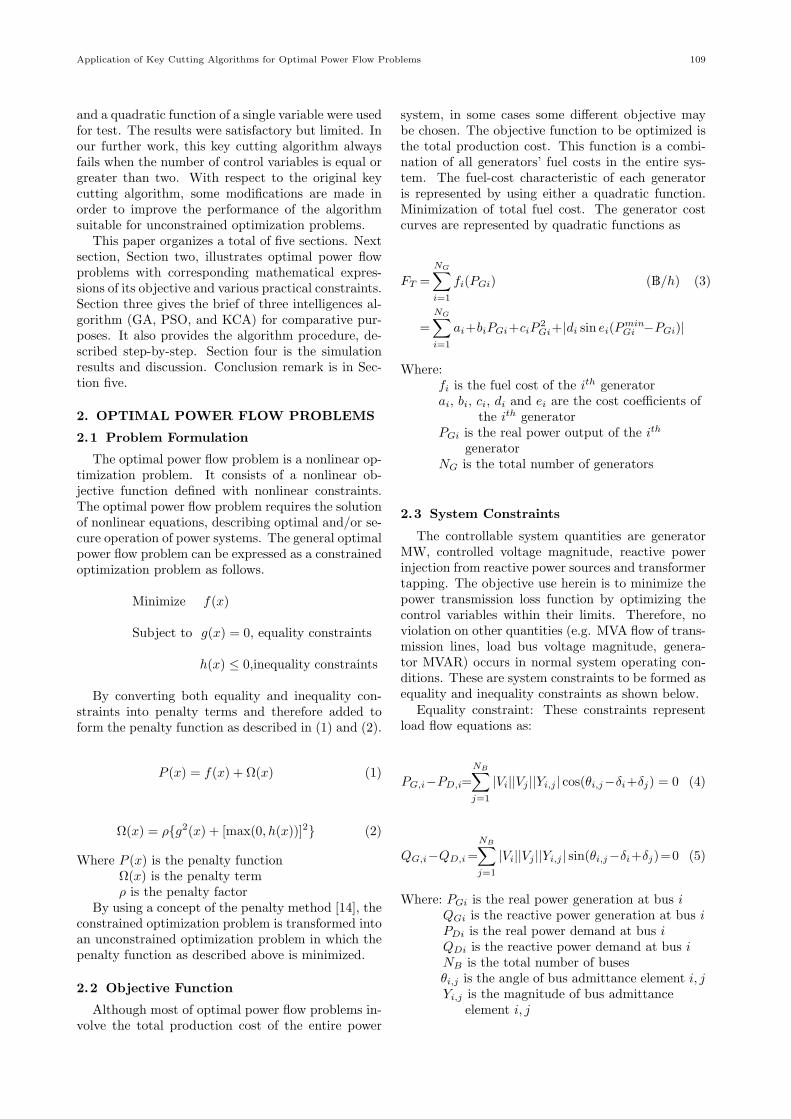
system, in some cases some different objective maybe chosen. The objective function to be optimized isthe total production cost. This function is a combi-nation of all generators’ fuel costs in the entire sys-tem. The fuel-cost characteristic of each generatoris represented by using either a quadratic function.Minimization of total fuel cost. The generator costcurves are represented by quadratic functions as
FT =
NG∑i=1
fi(PGi) (฿/h) (3)
=
NG∑i=1
ai+biPGi+ciP2Gi+|di sin ei(Pmin
Gi −PGi)|
Where:fi is the fuel cost of the ith generatorai, bi, ci, di and ei are the cost coefficients of
the ith generatorPGi is the real power output of the ith
generatorNG is the total number of generators
2.3 System Constraints
The controllable system quantities are generatorMW, controlled voltage magnitude, reactive powerinjection from reactive power sources and transformertapping. The objective use herein is to minimize thepower transmission loss function by optimizing thecontrol variables within their limits. Therefore, noviolation on other quantities (e.g. MVA flow of trans-mission lines, load bus voltage magnitude, genera-tor MVAR) occurs in normal system operating con-ditions. These are system constraints to be formed asequality and inequality constraints as shown below.
Equality constraint: These constraints representload flow equations as:
PG,i−PD,i=
NB∑j=1
|Vi||Vj ||Yi,j | cos(θi,j−δi+δj) = 0 (4)
QG,i−QD,i=
NB∑j=1
|Vi||Vj ||Yi,j | sin(θi,j−δi+δj)=0 (5)
Where: PGi is the real power generation at bus iQGi is the reactive power generation at bus iPDi is the real power demand at bus iQDi is the reactive power demand at bus iNB is the total number of busesθi,j is the angle of bus admittance element i, jYi,j is the magnitude of bus admittance
element i, j
110 ECTI TRANSACTIONS ON ELECTRICAL ENG., ELECTRONICS, AND COMMUNICATIONS VOL.10, NO.1 February 2012
1) Inequality constraint: Variable limitations
V mini ≤ Vi ≤ V max
i (6)
Tmini ≤ Ti ≤ Tmax
i (7)
Qmincomp,i ≤ Qcomp,i ≤ Qmax
comp,i (8)
PminG,i ≤ PG,i ≤ Pmax
G,i (9)
Where: V mini , V max
i are upper and lower limits ofvoltage magnitude at bus iTmini , Tmax
i are upper and lower limits of tapposition of transformer iQmin
comp,i, Qmaxcomp,iare upper and lower limits
of reactive power source iPminG,i , Pmax
G,i are upper and lower limits ofpower generated by generator i
2.4 Control Parameters
Initially, the KCA was designed to work on abinary-valued encoding representation of the problemparameters. During the searching process, a lock-smith as a collection of the key set represents a so-lution vector (keys). Let xi be a created key set aspossible solutions. The power output of all generat-ing units (P , Q), the voltage magnitude and angle of
all buses (|V |, δ) and the tapping value of all trans-
formers (T ) and reactive power injection from reac-
tive power compensators (Qc) are typical members ofthe solution vector and it can be written as describedin (10).
xi =[P Q |V | δ T QC
]T(10)
2.5 Control Parameters
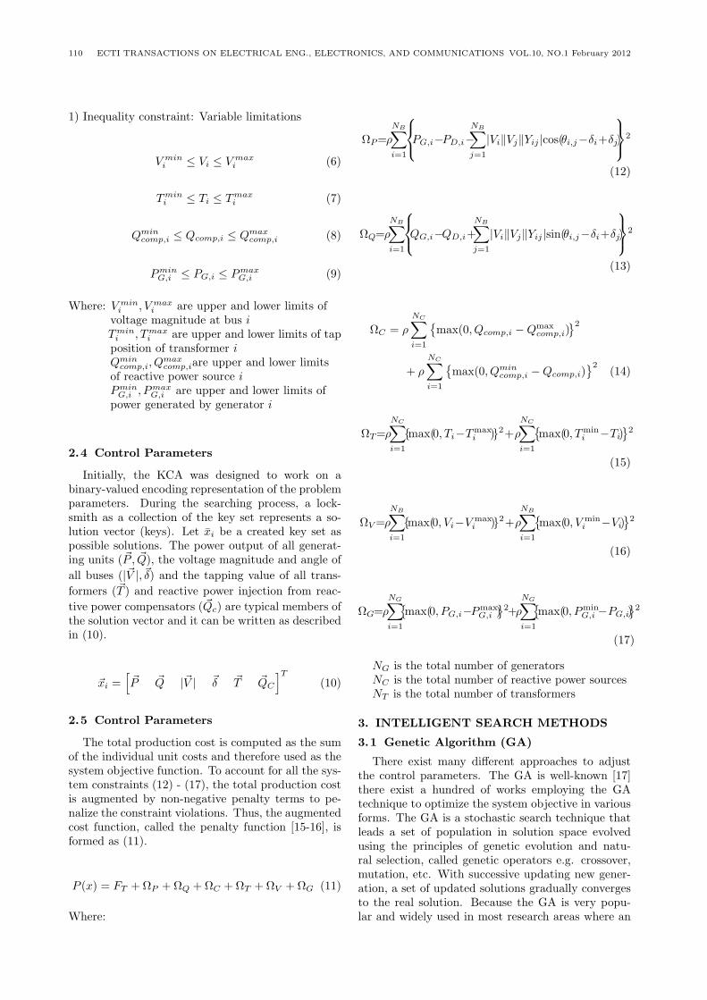
The total production cost is computed as the sumof the individual unit costs and therefore used as thesystem objective function. To account for all the sys-tem constraints (12) - (17), the total production costis augmented by non-negative penalty terms to pe-nalize the constraint violations. Thus, the augmentedcost function, called the penalty function [15-16], isformed as (11).
P (x) = FT +ΩP +ΩQ +ΩC +ΩT +ΩV +ΩG (11)
Where:
ΩP=ρ
NB∑i=1
PG,i−PD,i−NB∑j=1
|Vi∥Vj∥Yij |cos(θi,j−δi+δj)
2
(12)
ΩQ=ρ
NB∑i=1
QG,i−QD,i+
NB∑j=1
|Vi∥Vj∥Yij |sin(θi,j−δi+δj)
2
(13)
ΩC = ρ
NC∑i=1
max(0, Qcomp,i −Qmax
comp,i)2
+ ρ
NC∑i=1
max(0, Qmin
comp,i −Qcomp,i)2
(14)
ΩT=ρ
NC∑i=1
max(0, Ti−Tmaxi )2+ρ
NC∑i=1
max(0, Tmin
i −Ti)2
(15)
ΩV=ρ
NB∑i=1
max(0, Vi−V maxi )2+ρ
NB∑i=1
max(0, V min
i −Vi)2
(16)
ΩG=ρ
NG∑i=1
max(0, PG,i−Pmax
G,i )2+ρ
NG∑i=1
max(0, Pmin
G,i −PG,i)2
(17)
NG is the total number of generatorsNC is the total number of reactive power sourcesNT is the total number of transformers
3. INTELLIGENT SEARCH METHODS
3.1 Genetic Algorithm (GA)
There exist many different approaches to adjustthe control parameters. The GA is well-known [17]there exist a hundred of works employing the GAtechnique to optimize the system objective in variousforms. The GA is a stochastic search technique thatleads a set of population in solution space evolvedusing the principles of genetic evolution and natu-ral selection, called genetic operators e.g. crossover,mutation, etc. With successive updating new gener-ation, a set of updated solutions gradually convergesto the real solution. Because the GA is very popu-lar and widely used in most research areas where an
Application of Key Cutting Algorithms for Optimal Power Flow Problems 111
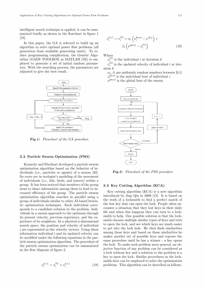
intelligent search technique is applied, it can be sum-marized briefly as shown in the flowchart in figure 1[18].
In this paper, the GA is selected to build up analgorithm to solve optimal power flow problems (allgeneration from available generating units). To re-duce programming complication, the Genetic Algo-rithm (GADS TOOLBOX in MATLAB [19]) is em-ployed to generate a set of initial random parame-ters. With the searching process, the parameters areadjusted to give the best result.
Fig.1: Flowchart of the GA procedure
3.2 Particle Swarm Optimization (PSO)
Kennedy and Eberhart developed a particle swarmoptimization algorithm based on the behavior of in-dividuals (i.e., particles or agents) of a swarm [20].Its roots are in zoologist’s modeling of the movementof individuals (i.e., fish, birds, and insects) within agroup. It has been noticed that members of the groupseem to share information among them to lead to in-creased efficiency of the group. The particle swarmoptimization algorithm searches in parallel using agroup of individuals similar to other AI-based heuris-tic optimization techniques. Each individual corre-sponds to a candidate solution to the problem. Indi-viduals in a swarm approach to the optimum throughits present velocity, previous experience, and the ex-perience of its neighbors. In a physical n-dimensionalsearch space, the position and velocity of individuali are represented as the velocity vectors. Using theseinformation individual i and its updated velocity canbe modified under the following equations in the par-ticle swarm optimization algorithm. The procedure ofthe particle swarm optimization can be summarizedin the flow diagram of figure 2.
xk+1i = x
(k)i + vk+1
i (18)
vk+1i = v
(k)i + αi
(xlbesti − x(k)i
)+
βi
(xgbest − x
(k)i
)(19)
Wherex(k)i is the individual i at iteration k
v(k)i is the updated velocity of individual i at iter-
ation kαi, βi are uniformly random numbers between [0,1]xlbesti is the individual best of individual i
xgbest is the global best of the swarm
Fig.2: Flowchart of the PSO procedure
3.3 Key Cutting Algorithm (KCA)
Key cutting algorithm (KCA) is a new algorithmintroduced by Jing Qin in 2009 [13]. It is based onthe work of a locksmith to find a perfect match ofthe lost key that can open the lock. People often en-counter a situation that they lost keys in their dailylife and when this happens they can turn to a lock-smith to help. One possible solution is that the lock-smith chooses multiple similar types of keys and triesto open the lock, and see which keys are much easierto get into the lock hole. He then finds similaritiesamong those keys and based on those similarities hemakes another set of possible keys and repeats thesame procedure until he has a winner - a key opensthe lock. To make such problem more general, an ob-jective function of any problem can be considered asa lock without key and a solution to the problem is akey to open the lock. Similar procedures as the lock-smith does can be employed to solve the optimizationproblems. This algorithm can be described as follows.
112 ECTI TRANSACTIONS ON ELECTRICAL ENG., ELECTRONICS, AND COMMUNICATIONS VOL.10, NO.1 February 2012
A.DefinitionsDefinition 1 Lock: Problem requires solution. Forthis example the lock is Find the X when Y has theminimum value.Definition 2 Key: One possible solution for the prob-lem. For the quadratic equation problem, A real num-ber for X, like X = 4 is a key.Definition 3 Tooth: One component of the vector ofthe solution. One tooth on the key is one componentof the vector of the solution. Here, X is a real value;we can encode a real value with its binary format.X=5 (binary is 00000101)
Fig.3: One component of the vector of the solution
Definition 4 Key Set: A set of possible solutions.Definition 5 Fitness: The degree of how the key andlock matches. The differences between the candidatekey and the key open the lock.Definition 6 Similarity: The degree of similaritiesamong all keys in a key set.Definition 7 Key cutting: Adjust one tooth on thekey or change one component in the solution vector.For instance, X=5 (0000101B), change the 2nd toothfrom 0 to 1, 0101⇒0111.Definition 8 Probability factor of Key Cutting: Theprobability uses to control the variation of one tooth.For instance, X=5 (00000101B). This probability isused to control each 1 and 0 in 00000101 the proba-bility of changing from 1 to 0 or vice versa. In thekey cutting algorithm, the probability factor of keycutting is calculated based on the similarity in thekey set.Definition 9 Selection: Choose a subset from a keyset to go into next iteration.
B. Basic Algorithm procedureAssume a key is k= [sn, sn-1,. . .,s1]Step 1: Encoding the Key.Step 2: Random generate the initial Key Set K0, to-tal number of keys is 2m.Step 3: Calculate the Fitness of each Key in the Keyset.Step 4: Selection half of all Keys in the Key Set witha higher Fitness, which makes a new Key Set K1’Step 5: Calculate the Probability factor of Key Cut-tingpij(i = 1, 2,m; j = 1, 2, n) for each Tooth Sij .Use a matrix, the key vector in Key Set K1’:
pij =1-(the number of Sij in column J/m)Step 6: Based on pij, perform the Key Cutting foreach Tooth Sij in Key Set K1’. And create a new KeySet K1”. K1’ and K1” together makes up of Key SetK1
Step 7: Repeat 2 to 5 until one of the following con-dition is met, output the best Key in the final KeySet as the final solution.
Termination condition:1) reaches the maximum iteration.2) within predefined solution variance.3) All Keys are the same in the Key Set.
The key cutting algorithm can be summarized inthe following steps or as shown in figure 4.
Fig.4: : Flowchart of the KCA procedure
C. Modifications of the Key Cutting AlgorithmIn the original key cutting algorithm, it converges
to a solution very fast. However, in multivariate prob-lems, it usually fails to find the optimal solution. Akey set with key cutting probability is used and keypicking is repeatedly performed iteration-byiteration,until all keys are the same. The major disadvantageof this algorithm occurs when a majority of keys in akey set is not good enough to open the lock. The sim-ilarity acquired among those keys can cause a trap ofsolutions to force all keys in a key set being the same.To avoid such a trap, additional feature must be in-serted to create various candidates to open the lock.In this paper, four strategies are tried as follows.
Application of Key Cutting Algorithms for Optimal Power Flow Problems 113
Modification 1 (KCA1): Tooth adjustment is per-formed at only one tooth with the highest key cut-ting probability and the highest probability mustbe greater than 0.5, otherwise skip the adjustment.However, there might be more than one tooth havingthe same value of the highest probability, only onetooth will be selected randomly for simplification.
Modification 2 (KCA2): Similar to the modification1. To increase opportunity of finding a good key can-didate, all teeth having the same value of the highestprobability will be performed the tooth adjustment.Only one adjustment that gives the best fitness is se-lected to create a new key instead of using the randomselection as applied in Modification 1.
Modification 3 (KCA3): Tooth adjustment is appliedto all teeth having the probability higher than 0.5.Only one adjustment that gives the best fitness isselected to create a new key.
Modification 4 (KCA4): Similar to the modification3. However, if the key cutting probability of a newkey set is equal to the key cutting probability of thekey set from the previous iteration, then generate anew key set and restart the process.
4. RESULTS AND DISCUSSION
The test systems were separated into two groups.The first group consisted of four standard mathemat-ical functions test of small-scale. The second groupemployed three standard IEEE test power systemswhich were the 6-bus, 14-bus and 30-bus test powersystems [21]. The detail of each group was given asfollows.
4.1 Mathematical Test Functions
This paper uses the proposed algorithm to mini-mize the following two typical multi-peak functionswhich has many local extreme values. During theprocess of optimization, it is easy to become stuck inthese local minima and lead to a premature conver-gence. To compare results obtained by using geneticalgorithm and key cutting algorithm, all test caseswere simulated by using the same computer whichwas an Intelr, Core 2 Duo, 2.4 GHz, 3.0 GB RAM.
4.1...1 Test Function 1
The test of this function is carried out by apply-ing the same parameter setting to all the key cuttingalgorithms and genetic algorithms as follows.
• Population size is 80• Maximum iteration is 50• No stalled generation is applied• 16-bit resolution is used for each variable
f(x1, x2) = − sin(x1)
x1× sin(x2)
x2(20)
For the test functions 1 shown as equation (20)[22] has infinitely local minima. The point (0,0) issaid to be the global minimum. The objective at itsglobal minimum is 0 as the 3D characteristic of thetest function 1 shown in figure 5. In table 1 and2 are fitness value solution, average CPU computa-tional time and an optimal solution adjustment foreach method. Comparisons of the convergence amongGA and KCA for the test function one were presentedin figure 6.
Fig.5: 3D characteristic of the test function 1
After 30 trials of solutions, the selected conver-gence from each method is shown in figure 6. KCA2and KCA4 are the two best methods for finding
Fig.6: Convergences of the test function 1
Table 1: Statistic of fitness value and average CPUcomputational time for the test function 1
114 ECTI TRANSACTIONS ON ELECTRICAL ENG., ELECTRONICS, AND COMMUNICATIONS VOL.10, NO.1 February 2012
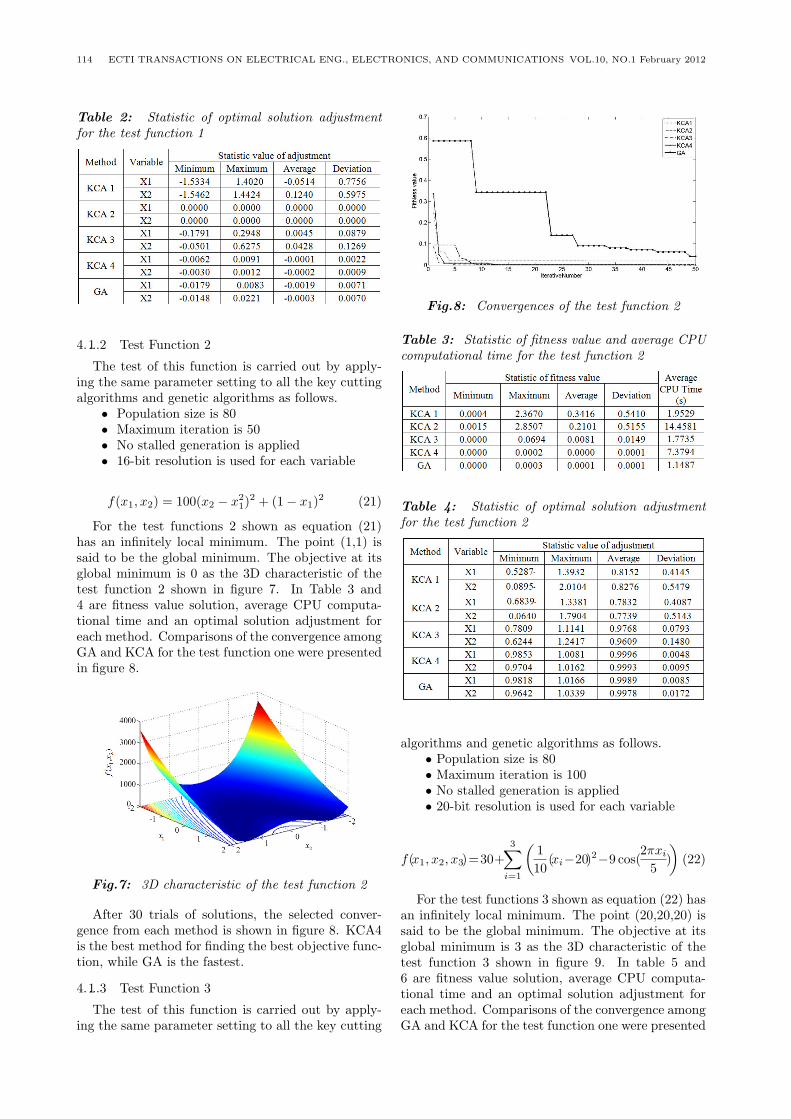
Table 2: Statistic of optimal solution adjustmentfor the test function 1
4.1...2 Test Function 2
The test of this function is carried out by apply-ing the same parameter setting to all the key cuttingalgorithms and genetic algorithms as follows.
• Population size is 80• Maximum iteration is 50• No stalled generation is applied• 16-bit resolution is used for each variable
f(x1, x2) = 100(x2 − x21)
2 + (1− x1)2 (21)
For the test functions 2 shown as equation (21)has an infinitely local minimum. The point (1,1) issaid to be the global minimum. The objective at itsglobal minimum is 0 as the 3D characteristic of thetest function 2 shown in figure 7. In Table 3 and4 are fitness value solution, average CPU computa-tional time and an optimal solution adjustment foreach method. Comparisons of the convergence amongGA and KCA for the test function one were presentedin figure 8.
Fig.7: 3D characteristic of the test function 2
After 30 trials of solutions, the selected conver-gence from each method is shown in figure 8. KCA4is the best method for finding the best objective func-tion, while GA is the fastest.
4.1...3 Test Function 3
The test of this function is carried out by apply-ing the same parameter setting to all the key cutting
Fig.8: Convergences of the test function 2
Table 3: Statistic of fitness value and average CPUcomputational time for the test function 2
Table 4: Statistic of optimal solution adjustmentfor the test function 2
algorithms and genetic algorithms as follows.• Population size is 80• Maximum iteration is 100• No stalled generation is applied• 20-bit resolution is used for each variable
f(x1, x2, x3)=30+3∑
i=1
(1
10(xi−20)2−9 cos(
2πxi
5)
)(22)
For the test functions 3 shown as equation (22) hasan infinitely local minimum. The point (20,20,20) issaid to be the global minimum. The objective at itsglobal minimum is 3 as the 3D characteristic of thetest function 3 shown in figure 9. In table 5 and6 are fitness value solution, average CPU computa-tional time and an optimal solution adjustment foreach method. Comparisons of the convergence amongGA and KCA for the test function one were presented
Application of Key Cutting Algorithms for Optimal Power Flow Problems 115
in figure 10.
Fig.9: 3D characteristic of the test function 3
After 30 trials of solutions, the selected conver-gence from each method is shown in figure 10. KCA4and GA are the two best methods for finding the bestobjective function, while only GA is the fastest.
Table 5: Statistic of fitness value and average CPUcomputational time of the test function 3
Table 6: Statistic of optimal solution adjustment ofthe test function 3
4.1...4 Test Function 4
The test of this function is carried out by apply-ing the same parameter setting to all the key cuttingalgorithms and genetic algorithms as follows.
• Population size is 30• Maximum iteration is 50
Fig.10: Convergences of the test function 3
• No stalled generation is applied• 16-bit resolution is used for each variable
For the test functions 4 shown as equation (23)has an infinitely local minimum. The point (0,0) issaid to be the global minimum. The objective at itsglobal minimum is 0 as the 3D characteristic of thetest function 4 shown in figure 11. In table 7 and8 are fitness value solution, average CPU computa-tional time and an optimal solution adjustment foreach method. Comparisons of the convergence amongGA and KCA for the test function one were presentedin figure 12.
f(x1, x2) = 0.5 +sin2
√x21 + x2
2 − 0.5
(1 + 0.001 ∗ (x21 + x2
2))2
(23)
For the test functions 4 shown as equation (23)has an infinitely local minimum. The point (0,0) issaid to be the global minimum. The objective at itsglobal minimum is 0 as the 3D characteristic of thetest function 4 shown in figure 11. In table 7 and8 are fitness value solution, average CPU computa-tional time and an optimal solution adjustment foreach method. Comparisons of the convergence amongGA and KCA for the test function one were presentedin figure 12.
Fig.11: 3D characteristic of the test function 4
After 30 trials of solutions, the selected conver-gence from each method is shown in figure 12. KCA4is the best method for finding the best objective func-tion, while GA is the fastest.
116 ECTI TRANSACTIONS ON ELECTRICAL ENG., ELECTRONICS, AND COMMUNICATIONS VOL.10, NO.1 February 2012
Fig.12: Convergences of the test function 4
Table 7: Statistic of fitness value and average CPUcomputational time of the test function 4
Table 8: Statistic of optimal solution adjustment ofthe test function 4
4.2 IEEE Standard Test Systems
Although a modern electric power system consistsof many types of power plants, in this research thetests focused on fossil power generation units only.A simple model of such a generator is made from itsinput fuel cost in /h and corresponding power out-put generated in MW as input and output variables,respectively [18]. The test case scenarios were di-vided into two main conditions. There were smoothand non-smooth fuel-cost curve conditions. In thesmooth curve case, all generators’ fuel-cost curveswere quadratic whilst the second test employed avalve-point loading function [23,24]. Fuel cost func-tion of each generator connected to the system is gen-erally given in the form of valve-point loading func-tion with having a quadratic term in it.
4.2...1 Smooth fuel cost case - quadratic cost func-tion
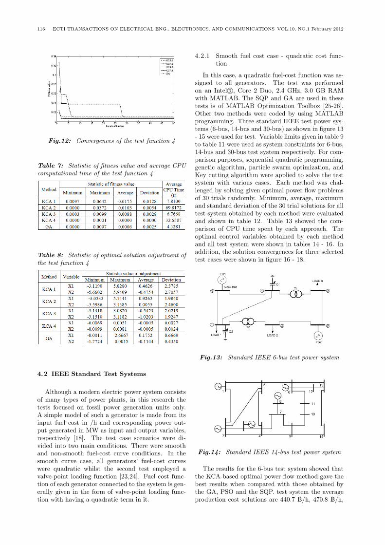
In this case, a quadratic fuel-cost function was as-signed to all generators. The test was performedon an Intelr, Core 2 Duo, 2.4 GHz, 3.0 GB RAMwith MATLAB. The SQP and GA are used in thesetests is of MATLAB Optimization Toolbox [25-26].Other two methods were coded by using MATLABprogramming. Three standard IEEE test power sys-tems (6-bus, 14-bus and 30-bus) as shown in figure 13- 15 were used for test. Variable limits given in table 9to table 11 were used as system constraints for 6-bus,14-bus and 30-bus test system respectively. For com-parison purposes, sequential quadratic programming,genetic algorithm, particle swarm optimization, andKey cutting algorithm were applied to solve the testsystem with various cases. Each method was chal-lenged by solving given optimal power flow problemsof 30 trials randomly. Minimum, average, maximumand standard deviation of the 30 trial solutions for alltest system obtained by each method were evaluatedand shown in table 12. Table 13 showed the com-parison of CPU time spent by each approach. Theoptimal control variables obtained by each methodand all test system were shown in tables 14 - 16. Inaddition, the solution convergences for three selectedtest cases were shown in figure 16 - 18.
Fig.13: Standard IEEE 6-bus test power system
Fig.14: Standard IEEE 14-bus test power system
The results for the 6-bus test system showed thatthe KCA-based optimal power flow method gave thebest results when compared with those obtained bythe GA, PSO and the SQP. test system the averageproduction cost solutions are 440.7 ฿/h, 470.8 ฿/h,
Application of Key Cutting Algorithms for Optimal Power Flow Problems 117
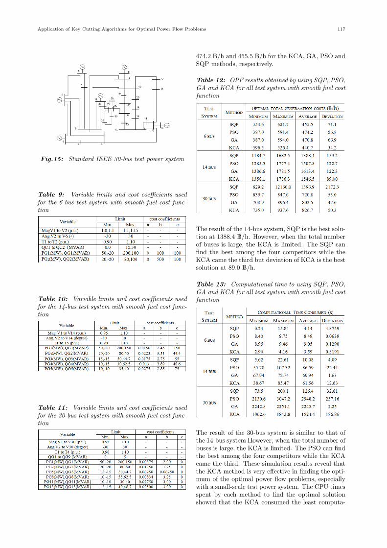
Fig.15: Standard IEEE 30-bus test power system
Table 9: Variable limits and cost coefficients usedfor the 6-bus test system with smooth fuel cost func-tion
Table 10: Variable limits and cost coefficients usedfor the 14-bus test system with smooth fuel cost func-tion
Table 11: Variable limits and cost coefficients usedfor the 30-bus test system with smooth fuel cost func-tion
474.2 ฿/h and 455.5 ฿/h for the KCA, GA, PSO andSQP methods, respectively.
Table 12: OPF results obtained by using SQP, PSO,GA and KCA for all test system with smooth fuel costfunction
The result of the 14-bus system, SQP is the best solu-tion at 1388.4 ฿/h. However, when the total numberof buses is large, the KCA is limited. The SQP canfind the best among the four competitors while theKCA came the third but deviation of KCA is the bestsolution at 89.0 ฿/h.
Table 13: Computational time to using SQP, PSO,GA and KCA for all test system with smooth fuel costfunction
The result of the 30-bus system is similar to that ofthe 14-bus system However, when the total number ofbuses is large, the KCA is limited. The PSO can findthe best among the four competitors while the KCAcame the third. These simulation results reveal thatthe KCA method is very effective in finding the opti-mum of the optimal power flow problems, especiallywith a small-scale test power system. The CPU timesspent by each method to find the optimal solutionshowed that the KCA consumed the least computa-
118 ECTI TRANSACTIONS ON ELECTRICAL ENG., ELECTRONICS, AND COMMUNICATIONS VOL.10, NO.1 February 2012
Table 14: Optimal solution by each method for the6-bus system with smooth fuel cost function
Table 15: Optimal solution by each method for the14-bus system with smooth fuel cost function
tional time effort for 6 bus test system, However SQPconsumed the least computational time effort for 14and 30 bus test system.
Table 16: Optimal solution by each method for the30-bus system with smooth fuel cost function
Fig.16: Convergence characteristics of each methodfor the 6-bus test system with smooth fuel cost func-tion
Fig.17: Convergence characteristics of each methodfor the 14-bus test system with smooth fuel cost func-tion
Fig.18: Convergence characteristics of each methodfor the 30-bus test system with smooth fuel cost func-tion
4.2...2 Non-smooth fuel cost case - valve point load-ing
In this case, a valve-effect fuel-cost function wasassigned to all generators. Three standard IEEE testpower systems (6-bus, 14-bus and 30-bus) were usedfor test. Variable limits given in table 16 to table18 were used as system constraints for 6-bus, 14-busand 30-bus test system respectively. For comparisonpurposes, sequential quadratic programming, geneticalgorithm and key cutting algorithm were applied tosolve the test system with various cases. Each method
Application of Key Cutting Algorithms for Optimal Power Flow Problems 119
was challenged by solving given optimal power flowproblems of 30 trials randomly. Minimum, average,maximum and standard deviation of the 30 trial so-lutions for all test system obtained by each methodwere evaluated and shown in table 19. Table 20showed the comparison of CPU time spent by eachapproach. The optimal control variables obtained byeach method and all test system were shown in tables21 - 23.
Table 17: Variable limits and cost coefficients usedfor the 6-bus test system with non- smooth fuel costfunction
The results show that, for the 6-bus system, theKCA can again obtain the lowest averaged minimumcost function (609.6 ฿/h, 635.5 ฿/h and 614.4 ฿/hfor KCA, GA and SQP respectively). Due to a smallnumber of control variables to be optimized, the SQPcan be an appropriate choice of solving the optimalpower flow problem even the fuel-cost function is non-smooth. The result of the 14-bus system, when com-paring the averaged minimum costs obtained amongthose methods, the SQP is the best method (1749.5฿/h for the SQP, 1991.0 ฿/h for the GA and 1998.6฿/h for the KCA). However, with calculation timecomparison, the KCA method can obtain the solu-tion with the second calculation average time con-sumed (16.69 s) better than GA-based, while the fastmethod is SQP consumed average time at 15.46 s.The last test system is the 30-bus test system. TheKCA is the best method (518.7 ฿/h for the KCA,526.3 ฿/h for the GA and 766.1 ฿/h for the SQP).However, the KCA is the slowest method to find thesolution. The solution convergences for each test casewere shown in figure 19 - 21. Although the SQP is thefastest method, the KCA can find the most accuratesolution with satisfactory CPU time consumed.
Table 18: Variable limits and cost coefficients usedfor the 14-bus test system with non- smooth fuel costfunction
Table 19: Variable limits and cost coefficients usedfor the 30-bus test system with non- smooth fuel costfunction
Table 20: OPF Results Obtained by using SQP,GA and KCA for all Test System with non-smoothfuel cost function
Table 21: Computational Time to using SQP, GAand KCA for all Test System with non-smooth fuelcost function
Table 22: Optimal solution by each method for the6-bus system with non-smooth fuel cost function
120 ECTI TRANSACTIONS ON ELECTRICAL ENG., ELECTRONICS, AND COMMUNICATIONS VOL.10, NO.1 February 2012
Table 23: Optimal solution by each method for the14-bus system with non-smooth fuel cost function
Table 24: Optimal solution by each method for the30-bus system with non-smooth fuel cost function
Fig.19: Convergence characteristics of each methodfor the 6-bus test system with non-smooth fuel costfunction
Fig.20: Convergence characteristics of each methodfor the 14-bus test system with non- smooth fuel costfunction
Fig.21: Convergence characteristics of each methodfor the 30-bus test system with non- smooth fuel costfunction
5. CONCLUSIONS
This paper described the use of key cutting al-gorithm to find optimal power flow solutions. Thiswork was conducted by 30 trials for both smooth andnon-smooth fuel-cost functions in which four stan-dard IEEE test power systems (6-bus, 14-bus and30-bus) were employed. The test also applied theSQP, the genetic algorithm (GA) and particle swarmoptimization of 30 trials each for comparison. Theresults showed that the key cutting algorithm can bethe accurate method with satisfactory time consumedamong all as it gives the smallest standard deviationof the 30 trial solutions for every test case. It alsorevealed that the SQP is suitable for optimal powerflow problems with smooth quadratic fuel-cost func-tions where the total number of buses is small.
6. ACKNOWLEDGEMENT
This work supported by the Thailand ResearchFund through the Royal Golden Jubilee Ph.D. Pro-gram (Grant No. PHD/0047/2551) to Uthen Leetonand Thanatchai Kulworawanichpong are acknowl-edged.
Application of Key Cutting Algorithms for Optimal Power Flow Problems 121
References
[1] A.H. El-Abiad and F.J. Jaimes, “A method foroptimum scheduling of power and voltage mag-nitude,” IEEE Transactions. Power Apparatusand System., Vol. PAS-88, pp. 413 - 422, 1969.
[2] M.O. Mansour and T.M. Abdel-Rahman, ”Non-linear VAR optimization using decompositionand coordination”, IEEE Transactions. PowerApparatus and System, Vol. PAS-103, pp. 246- 255, 1984.
[3] H.W. Dommel and W.F. Tinney, ”Optimalpower flow solutions”, IEEE Transactions. PowerApparatu. System, Vol. PAS-87, pp. 1866 - 1876,1968.
[4] A.J. Wood and B.F. Wollenburg, Power Gener-ation Operation and Control, 2 (John Wiley &Sons, 1996)
[5] Y. Hong-Tzer, Y. Pai-Chuan and H. Ching-Lien,”Evolutionary programming based economic dis-patch for units with non-smooth fuel cost func-tions”, IEEE Transactions Power System, Vol.11, pp. 112 - 118, 1996.
[6] W. Kit Po, ”Computational intelligence appli-cations in unit commitment, economic dispatchand load flow”, The 4th International Confer-ence on Advances in Power System Control, Op-eration and Management (APSCOM-97), vol. 1,pp. 54-59, 1997.
[7] D.C. Walters and G.B. Sheble, ”Genetic algo-rithm solution of economic dispatch with valvepoint loading”, IEEE Transactions on PowerSystem, Vol. 8, pp. 1325-1332, 1993.
[8] D. Khanh andW. Kit Po, ”Artificial intelligence-based machine-learning system for thermal gen-erator scheduling”, IEE Proceeding. Generation,Transmission and Distribution, Vol. 142, pp. 195- 201, 1995.
[9] J.T. Ma and L.L. Lai, ”Evolutionary program-ming approach to reactive power planning”, IEEProceeding. Generation, Transmission and Dis-tribution, Vol. 143, pp. 365 - 370, 1996.
[10] T.L. Nguyen and Q.A. Nguyen, ”Application ofartificial bee colony algorithm (ABC) for recon-figuring distribution network”, The 10th Inter-national Conference on Computer Modelling andSimulation (ICCMS-2011), Vol. 1, pp. 102-106,2010.
[11] D. Karaboga, ”A new design method based onartificial bees colony algorithm for digital IRRfilters”, Journal of the Franklin Institute, Vol.346, pp.328 - 348, 2009.
[12] D. Karaboga and B. Busturk, ”A powerful andefficient algorithm for numerical function op-timization: artificial bee colony optimization”,Journal of Global Optimization, Vol. 39, pp. 459- 471, 2007.
[13] J. Qin, ”A New Optimization Algorithm and ItsApplication - Key Cutting Algorithm”, In 2009
IEEE International Conference on Grey Systemsand Intelligent Services IEEE Press, New York,pp. 1537-1541, 2009.
[14] P. Dutta and A. K. Sinha, ”Voltage Stabil-ity Constrained Multi-objective Optimal PowerFlow using Particle Swarm Optimization”, 1stInternational Conference on Industrial and In-formation Systems, pp. 161 - 166, 8-11 August2006.
[15] J. Nocedal, and S.J. Wright, Numerical opti-mization, (Springer, 2000).
[16] S.G. Nash and A. Sofer, Linear and nonlinearprogramming, (McGraw-Hill, 1996).
[17] Z. Haibo, Z. Lizi and M. Fanling, ”Reactivepower optimization based on genetic algorithm”,International Power Conference on Power Sys-tem Technology, pp.1448 - 1453, 18-21 August1998.
[18] K. Somsai, A. Oonsivilai, A. Srikaew, and T.Kulworawanichpong, ”Optimal PI controller de-sign and simulation of a static var compen-sator using MATLAB’s SIMULINK”, The 7th
WSEAS International Conference on POWERSYSTEMS, Beijing, China, pp. 30 - 35, Septem-ber 2007.
[20] J. Hazra1 and A. K. Sinha, ”A Study on Realand Reactive Power Optimization using ParticleSwarm Optimization”, International Conferenceon Industrial and Information Systems, pp. 323- 328, 9-11 August 2007.
[21] Z. Haibo, Z. Lizi and M. Fanling, Reactive poweroptimization based on genetic algorithm, In-ternational Power Conference on Power SystemTechnology vol. 2, 18-21 August, pp. 1448 - 1453,1998.
[22] S. He., Q.H. Wu, J.R. Saunders, Group SearchOptimizer: An Optimization Algorithm Inspiredby Animal Searching Behavior. IEEE Transac-tions Evolutionary Computation 13, 973-990,2009.
[23] P.N. Biskas, N.P. Ziogos, A. Tellidou, C.E.Zoumas, A.G. Bakirtzis and V. Petridis, ”Com-parison of two metaheuristics with mathematicalprogramming methods for the solution of OPF”,Generation, Transmission and Distribution, Vol.153, pp. 16 - 24. , 2006.
[24] M.J. Rider, C.A. Castro, M.F. Bedrinana andA.V. Garcia, ”Towards a fast and robust interiorpoint method for power system applications”,Generation, Transmission and Distribution, Vol.151, pp. 575 - 581, 2004.
[25] K. Vaisakh, P. Praveena and S. Rama MohanaRao, ”Solving optimal power flow problems us-ing bacterial swarm optimization algorithm”, In-ternational Conference Advance in Power Sys-
122 ECTI TRANSACTIONS ON ELECTRICAL ENG., ELECTRONICS, AND COMMUNICATIONS VOL.10, NO.1 February 2012
tem Control,Operation and Management (AP-SCOM’09, pp. 1 - 7), 2009.
[26] X.P. Zhang and E.J. Handschin, ”Advanced im-plementation of UPFC in a nonlinear interior-point OPF”, Generation, Transmission and Dis-tribution, Vol. 148, pp. 489 - 496, 2006.
Uthen Leeton is a Ph.D. Studentof the School of Electrical Engineer-ing, Institute of Engineering, Surana-ree University of Technology, NakhonRatchasima, THAILAND. He receivedB.Eng. with first-class honour in Elec-trical Engineering from Suranaree Uni-versity of Technology, Thailand (2007).His fields of research interest include apower system analysis, optimization andartificial intelligent techniques. He has
joined the school since June 2009 and is a research assistantand a member in Power System Research Unit, Suranaree Uni-versity of Technology.
Thanatchai Kulworawanichpong isan associate professor of the School ofElectrical Engineering, Institute of En-gineering, Suranaree University of Tech-nology, Nakhon Ratchasima, THAI-LAND. He received B.Eng. with first-class honour in Electrical Engineeringfrom Suranaree University of Technol-ogy, Thailand (1997), M.Eng. in Elec-trical Engineering from ChulalongkornUniversity, Thailand (1999), and Ph.D.
in Electronic and Electrical Engineering from the Universityof Birmingham, United Kingdom (2003). His fields of researchinterest include a broad range of power systems, power elec-tronic, electrical drives and control, optimization and artificialintelligent techniques. He has joined the school since June 1998and is currently a leader in Power System Research, SuranareeUniversity of Technology, to supervise and co-supervise over15 postgraduate students.