Application of Linux Single Board Computers to Amateur Radio Willem A Schreüder AC0KQ [email protected]RMHAM University October 15, 2016 http://www.prinmath.com/ham/talks/ http://www.rmham.org/wordpress/course-syllabus
● Why Linux SBCs● Installing and Configuring the OS● BPQ Packet/RMS Gateway/APRS iGate● AllStarLink Repeater● Control and Monitoring● SDR● Questions and Pizza● Don't freak out over the number of slides. Most of
them take 10 seconds to cover.
Single Board Computers
● Full Linux boxes (today's topic)– Raspberry Pi
– Beaglebone
● Microcontrollers (not covered)– Arduino
– PICAXE
– BASIC Stamp
Why Linux SBCs?
● Runs a full Linux OS● Usable stand alone computer or server● Built in connectivity
– Ethernet networking
– USB and serial
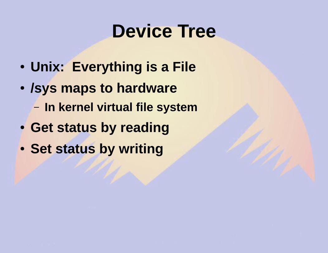
– General purpose IO
● Low power (5V 1A)● Expandable using daughter boards● Inexpensive ($50 for a working system)
SBC Pros and Cons
● Pros– Inexpensive
– No moving parts
– 5V power
– Expandable
● Cons– SD cards corrupted by bad power
– SD card is not a great hard disk
Raspberry Pi
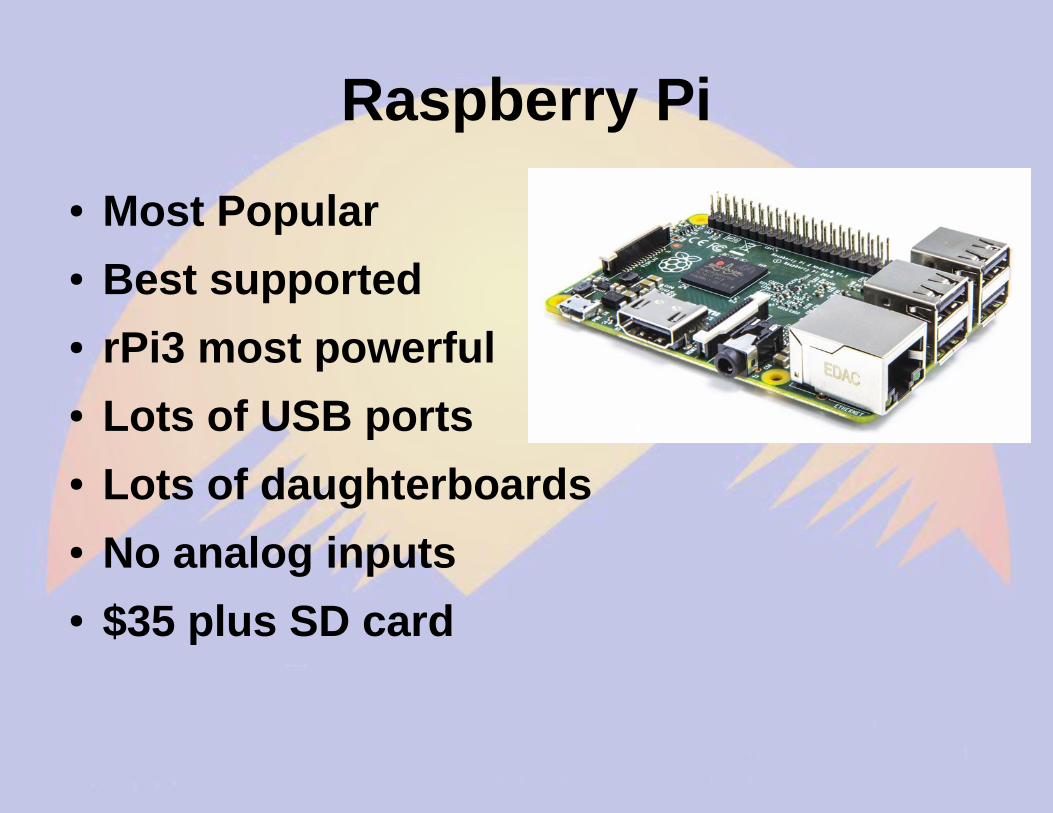
● Most Popular● Best supported● rPi3 most powerful● Lots of USB ports● Lots of daughterboards● No analog inputs● $35 plus SD card
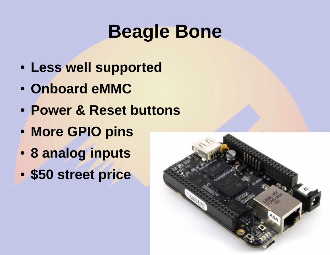
● Less well supported● Onboard eMMC● Power & Reset buttons● More GPIO pins● 8 analog inputs● $50 street price
Beaglebone Models
● White– Original 720 MHz A8
● Black– Most Popular 1GHz A8
● Green– Same CPU as Black
– No barrel power, two Grove connectors
● Industrial– Black with extended temperature range
Beagle Bone Black
Other Linux SBCs
● Examples– Intel Edison
– VoCore
– Odroid
● Less well supported● Fewer peripherals● Sometimes better performance● Mostly higher priced
Power and Storage
● Runs on 5V DC– Needs clean power
– Draws 0.5-1.0 A without daughter boards
● Micro SD card storage– Finite life
– Marginal performance
– Bad power kills SD
Must Have Accessories
● Micro SD card– Faster is better
● Class 10● UHS 1● UHS 3
– At least 4GB● 16GB is ample
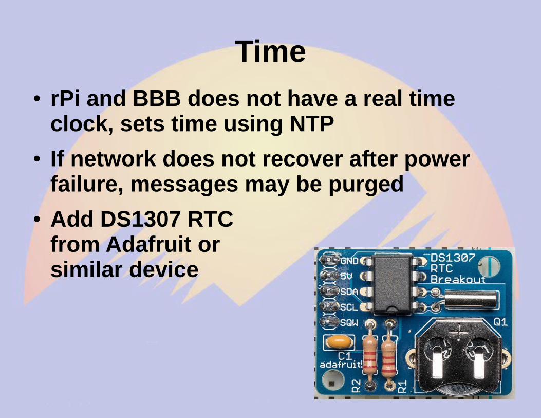
● Real time clock– PiFace Shim RTC
– Adafruit DS1307
– Needed if nonetwork (NTP)
Nice to have
● Official Raspberry 7” Touchscreen
Power Control
● Andice LabsPowercape
● Adafruit Powerboost 1000C
● Charges and boosts 4V from LIPO battery
TNC-X/Pi/Black
● Designed by John Hansen W2FS● Based on PIC Microcontroller● MX614 Bell 202 modem chip● KISS interface
– Serial
– USB
– I2C
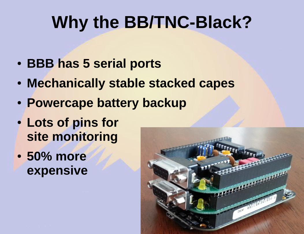
Why the BB/TNC-Black?
● BBB has 5 serial ports● Mechanically stable stacked capes● Powercape battery backup● Lots of pins for
site monitoring● 50% more
expensive
Part 1aGetting Started on the
Raspberry Pi
rPi Materials
● Raspberry Pi 2B or 3B● Micro SD card● 5V 1A power supply● USB A to micro USB B cable● Ethernet cable● Direct connection
– Monitor or TV
– HDMI cable
– USB keyboard and mouse
Raspberry OS Choices● https://www.raspberrypi.org/downloads/● Debian derivatives are most popular
– Raspbian (Official Supported OS)
– Alternatives are● NOOBS (New Out Of the Box Software)● Ubuntu Mate (Ubuntu Desktop)● Windows 10 IOT (a.k.a. YGBSM)● several others, some not Linux based
● Debian 8 (Jessie) adopts systemd– This changes how system programs are run
● No more /etc/init.d/XXX and /etc/inittab● Control programs with systemctl
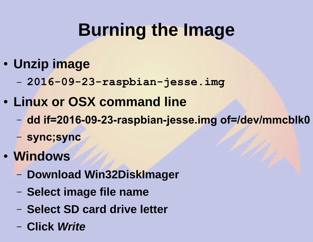
Burning the Image
● Unzip image– 2016-09-23-raspbian-jesse.img
● Linux or OSX command line– dd if=2016-09-23-raspbian-jesse.img of=/dev/mmcblk0
– sync;sync
● Windows– Download Win32DiskImager
– Select image file name
– Select SD card drive letter
– Click Write
First boot with Pixel
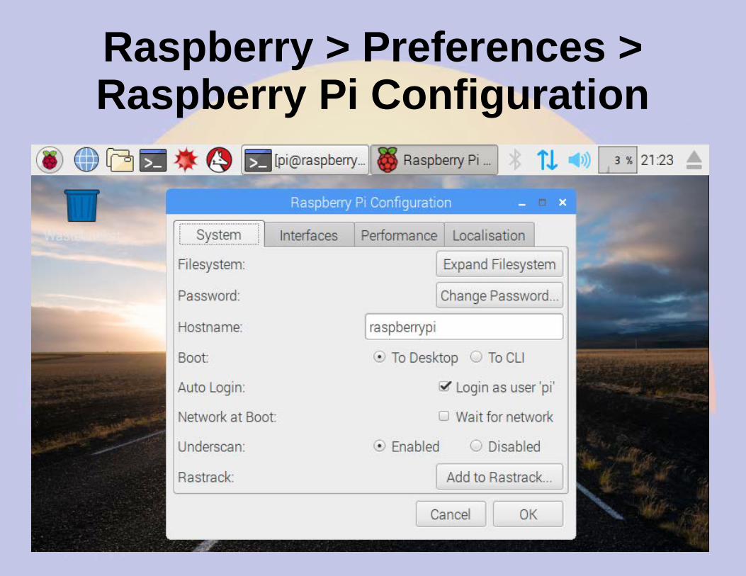
Raspberry > Preferences >Raspberry Pi Configuration
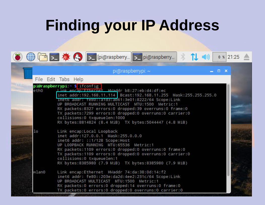
Finding your IP Address
Remote Access
● Do ifconfig from the keyboard● Look for hostname raspberrypi
– Assign a reserved IP address and add DNS
● Advantages of using ssh– Can access the device from anywhere
– Automatic logins using authorized_keys
– Text based menus work great remotely
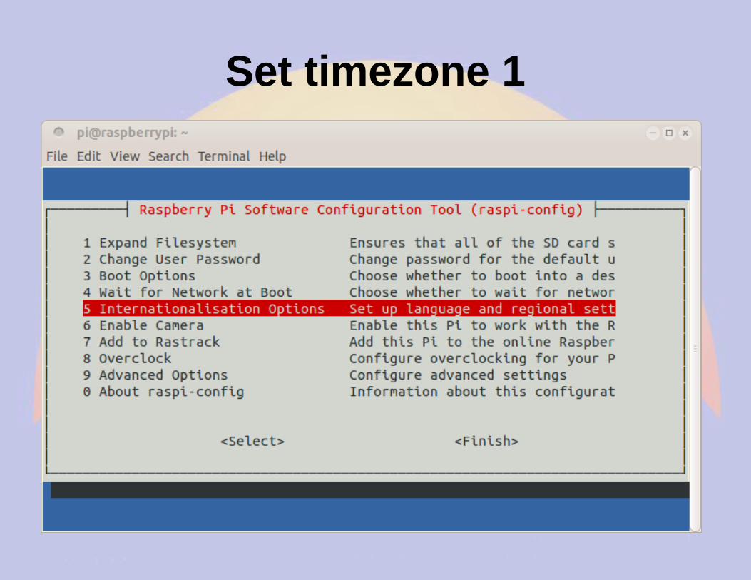
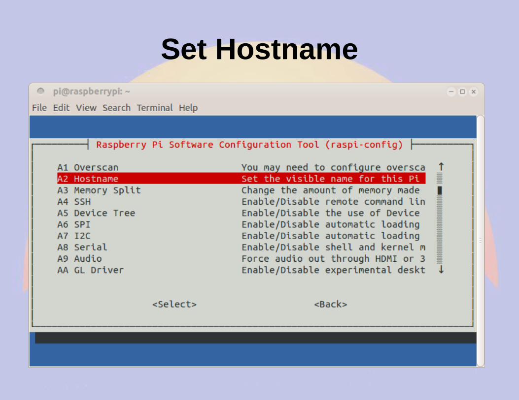
Configuring rPi
● Plug in keyboard, mouse and screen– Menu >Preferences > rPi Configuration
● Plug in ethernet cable and locate the IP address– Default hostname is raspberrypi
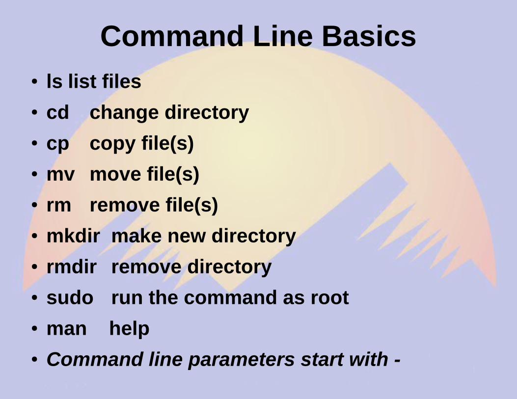
Command Line Basics● ls list files● cd change directory● cp copy file(s)● mv move file(s)● rm remove file(s)● mkdir make new directory● rmdir remove directory● sudo run the command as root● man help● Command line parameters start with -
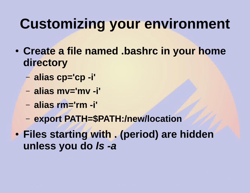
Customizing your environment
● Create a file named .bashrc in your home directory– alias cp='cp -i'
– alias mv='mv -i'
– alias rm='rm -i'
– export PATH=$PATH:/new/location
● Files starting with . (period) are hidden unless you do ls -a
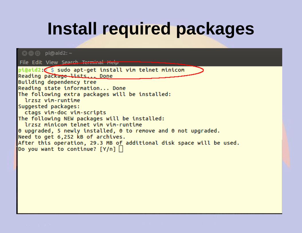
Software Maintenance
● apt-get update– Download index of latest software available
● apt-get upgrade– Upgrade all packages to latest versions
● apt-get install foo– Install package foo
● apt-get remove foo– Remove package foo
Editing files
● leafpad rPi editor● nano Easy to use● vi/vim/gvim The editor for real men● emacs For uber-nerds● BPQ has an editor built into the web
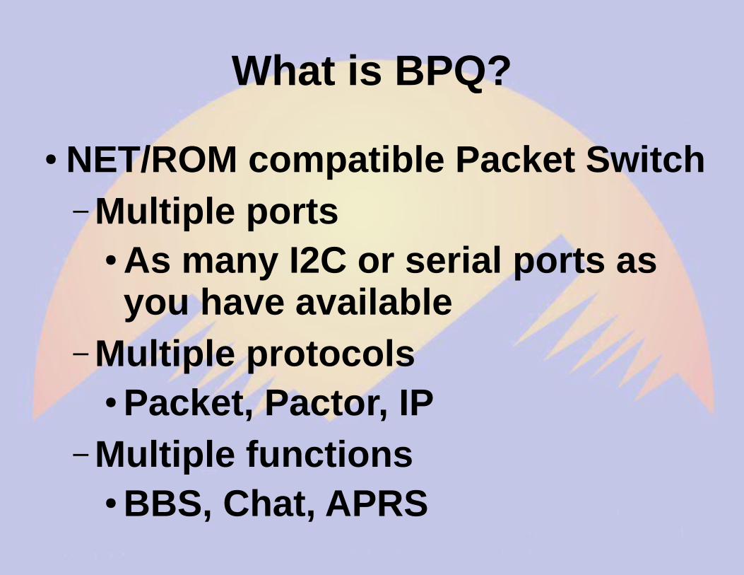
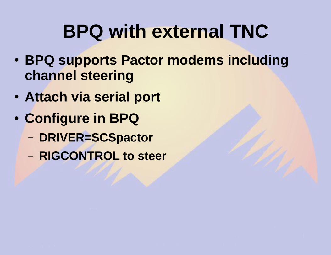
● As many I2C or serial ports as you have available
– Multiple protocols● Packet, Pactor, IP
– Multiple functions● BBS, Chat, APRS
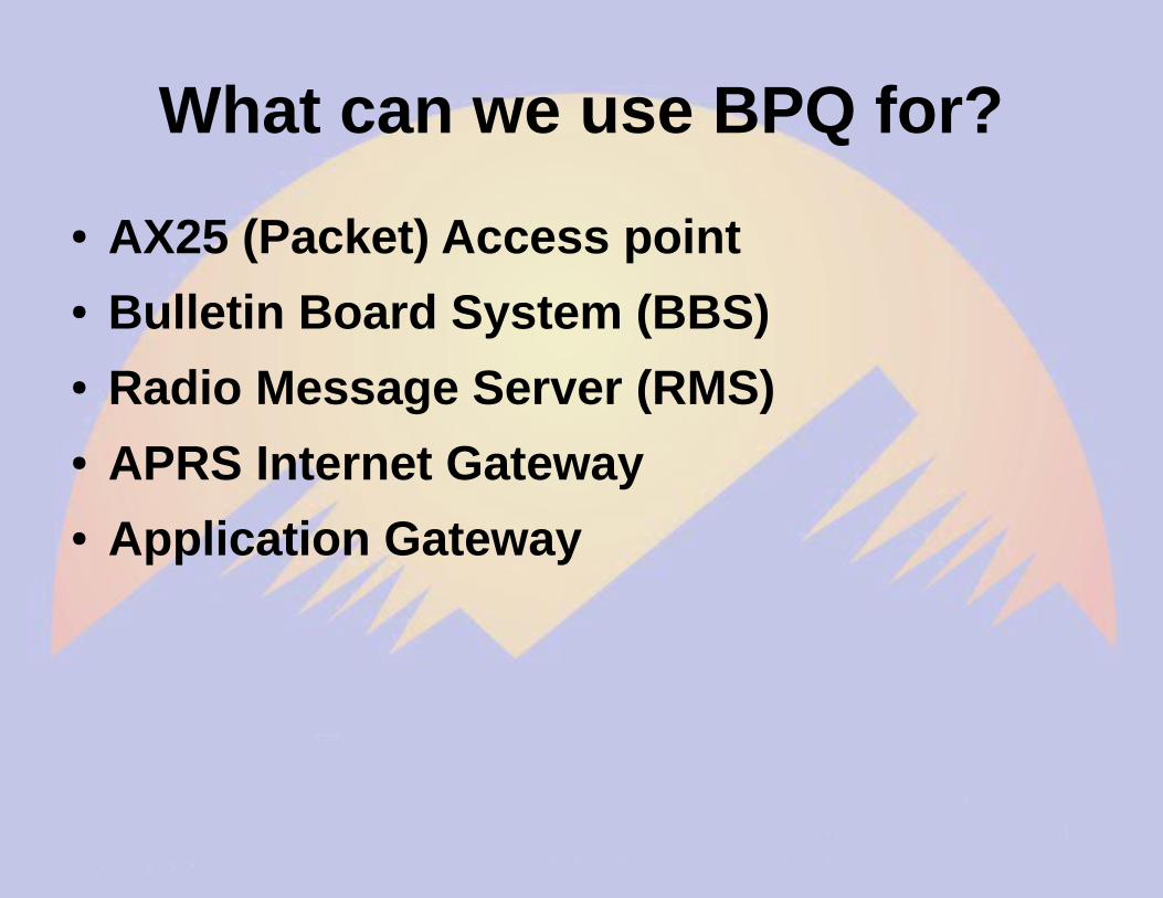
What can we use BPQ for?
● AX25 (Packet) Access point● Bulletin Board System (BBS)● Radio Message Server (RMS)● APRS Internet Gateway● Application Gateway
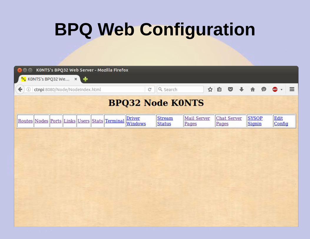
BPQ Web Configuration
BBS Message Page
Message Forwarding
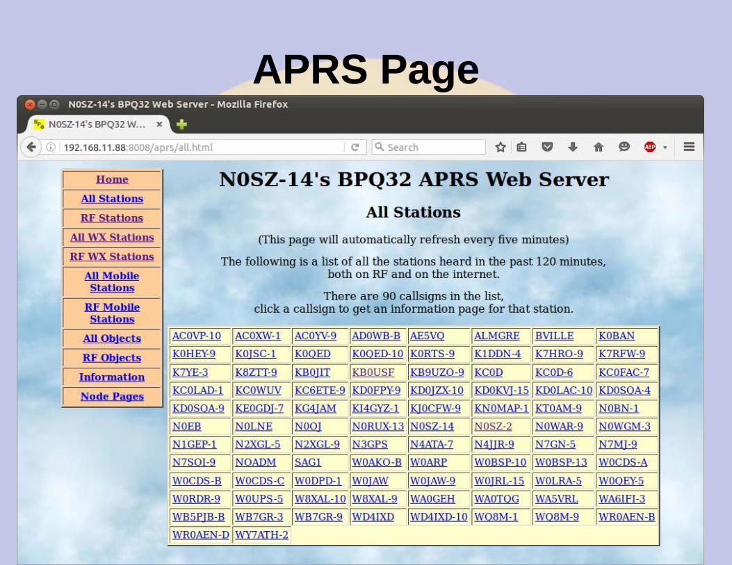
APRS Page
Stations Heard on RF
Station Map
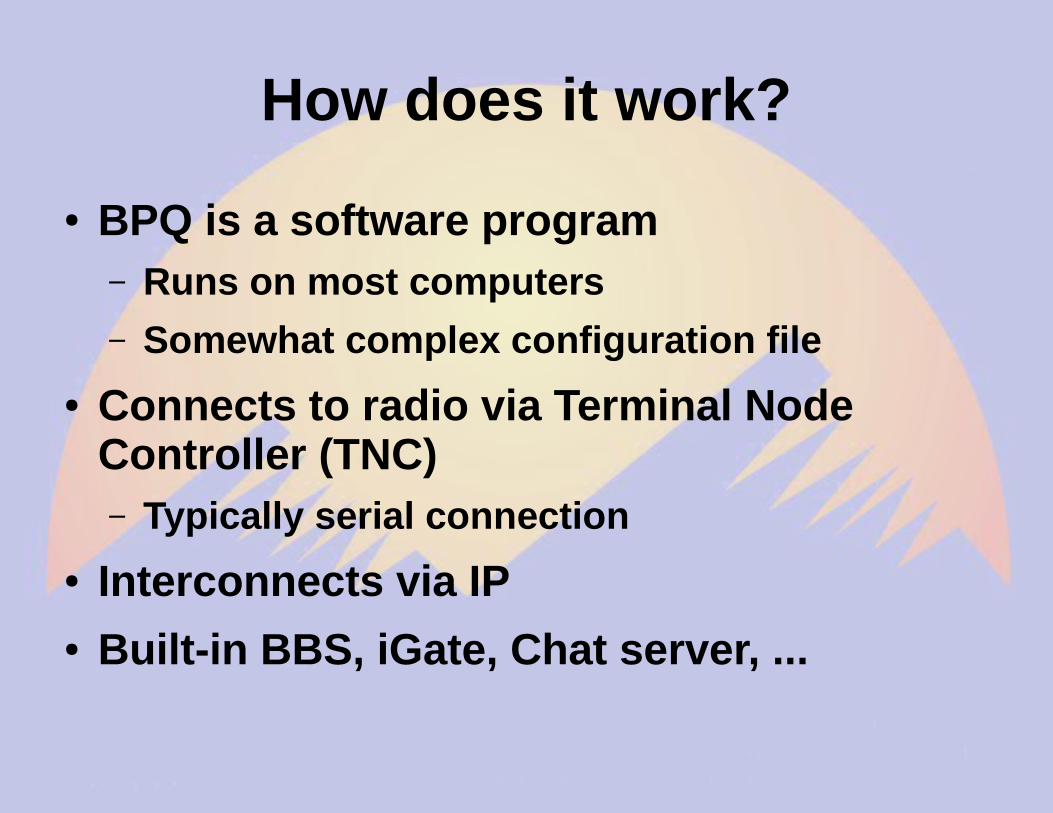
How does it work?
● BPQ is a software program– Runs on most computers
– Somewhat complex configuration file
● Connects to radio via Terminal Node Controller (TNC)– Typically serial connection
● Interconnects via IP● Built-in BBS, iGate, Chat server, ...
rPi/BPQ vs. KPC3+ BBS
● rPi/BPQ Pros– Lower cost ($100)
– Much larger capacity (GB vs. kB)
– More ports (multiple RF, serial and IP)
– Sophisticated forwarding
● rPi/BPQ Cons– Higher current draw
– Less tolerant of bad power
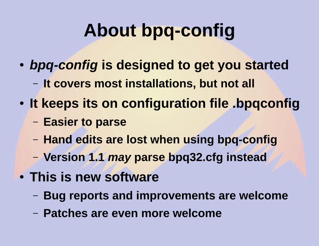
Complaint: Hard to set up BPQ
● BPQ is very sophisticated, and that necessarily adds complexity
● Solutions:– Use bpq-config to get started– Web interface for BBS etc.– Join a support group
● Yahoo BPQ32● RMHAM
Why so rPi and BBB centric?
● BPQ is software – runs anywhere– Supported on Windows, OSX, Linux– Best run as a headless server
● rPi and BBB are– Inexpensive– Reliable Linux boxes– DC powered– TNC/Pi & TNC/Black daughter boards– All the cool kids have one
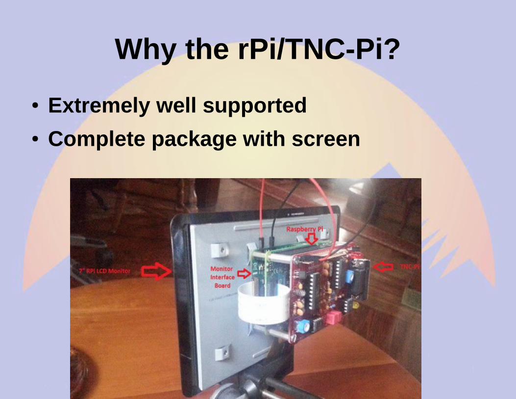
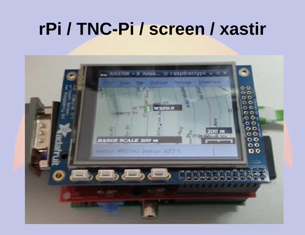
Why the rPi/TNC-Pi?
● Extremely well supported● Complete package with screen
Brief history of BPQ
● Written by John Wiseman G8BPQ● Originally called BPQCODE● Became BPQ32 in late 90s● Ported to OSX/Linux in 2000s● Ported to Raspberry Pi/TNC-PI and Beagle
Bone Black/TNC-Black
Building the TNC kit
● It takes a few hours to build– Quality soldering iron time
– Simple, excellent instructions
● Test it– Check voltages, insert ICs
– LEDs should flash on power up
– Configure OS and BPQ
● John W2FS provides outstanding after-sales support
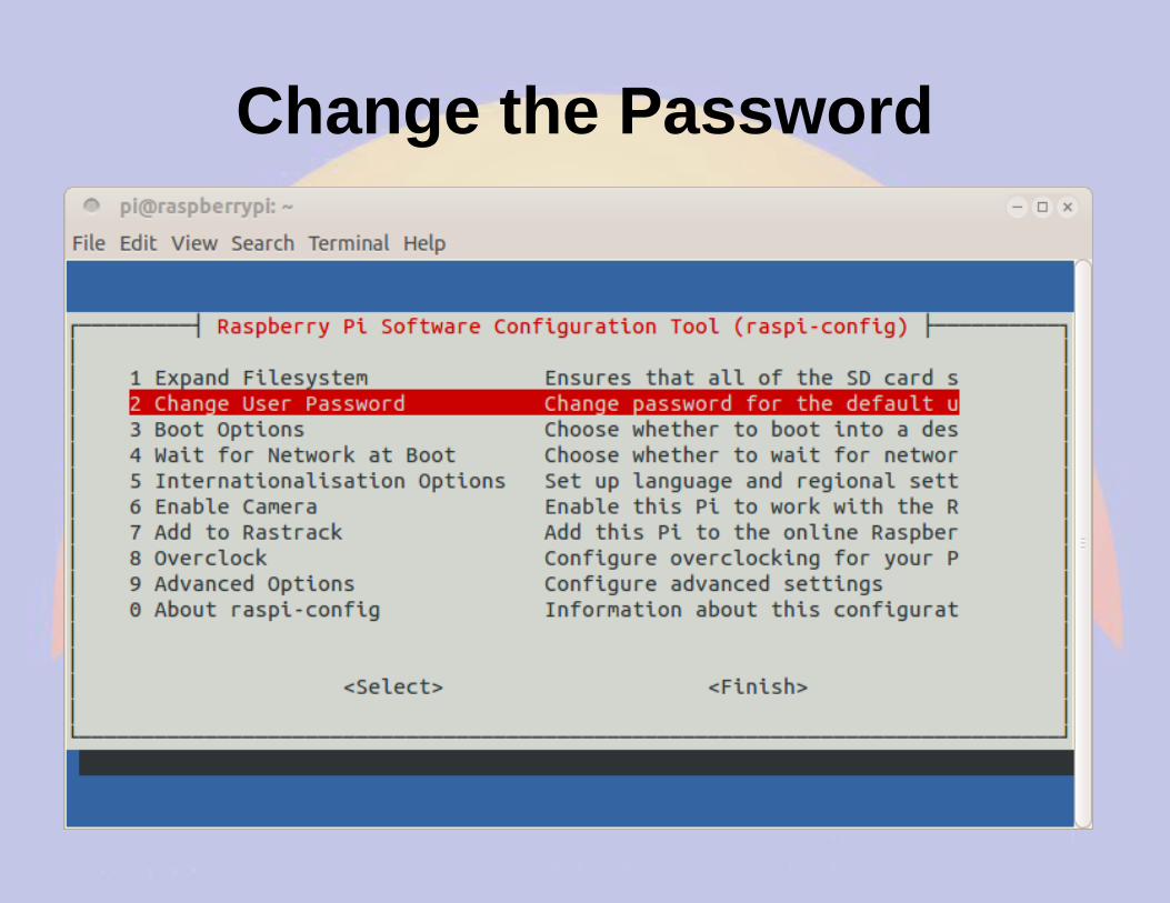
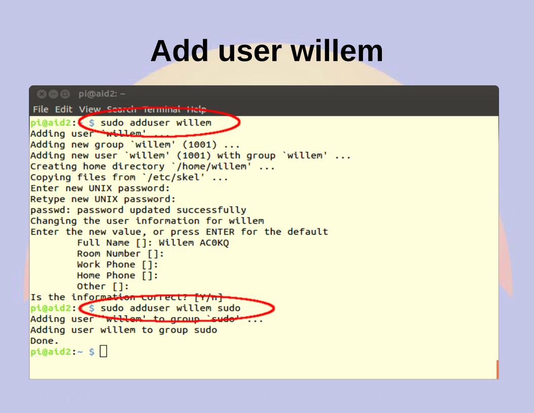
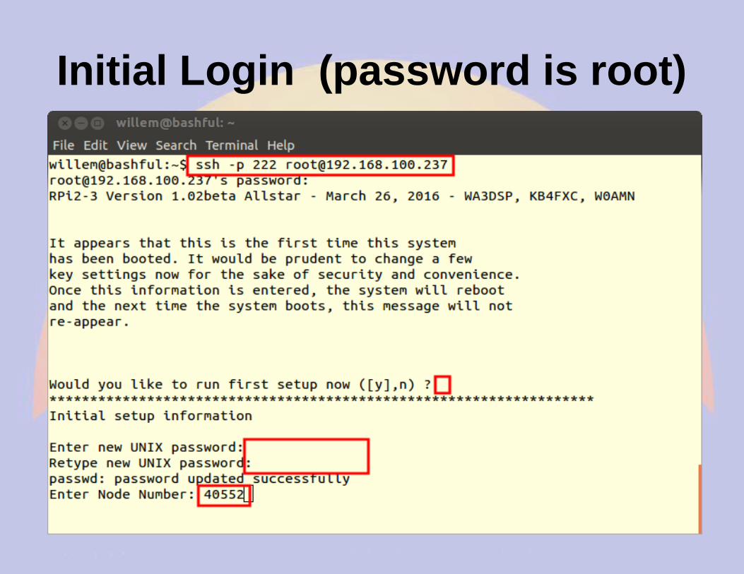
Selecting a Username
● Default user name– Raspberry Pi = pi
– Beaglebone Black = debian
● The default user name is good for BPQ and similar programs with multiple users
● Create a login for each user● Create subdirectories for programs like
BPQ which will clutter the home directory
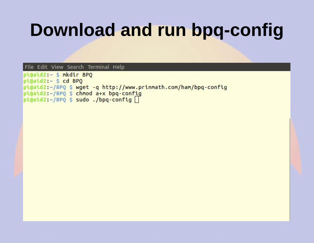
Download and run bpq-config
Download BPQ(Can also be used to update BPQ)
Configure BPQ
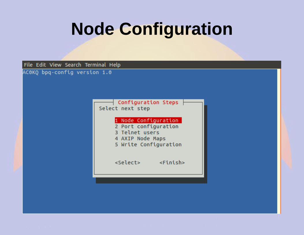
Node Configuration
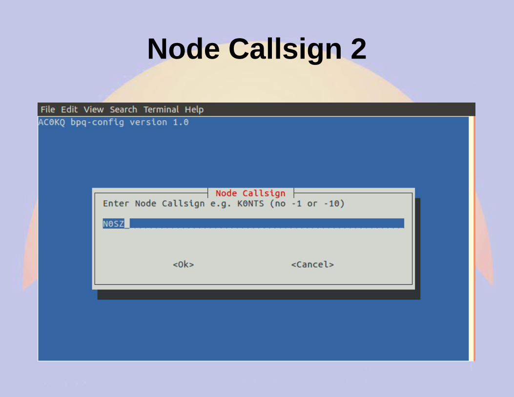
Node Callsign 1
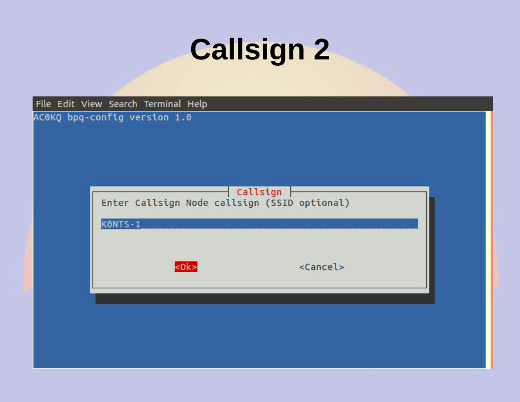
Node Callsign 2
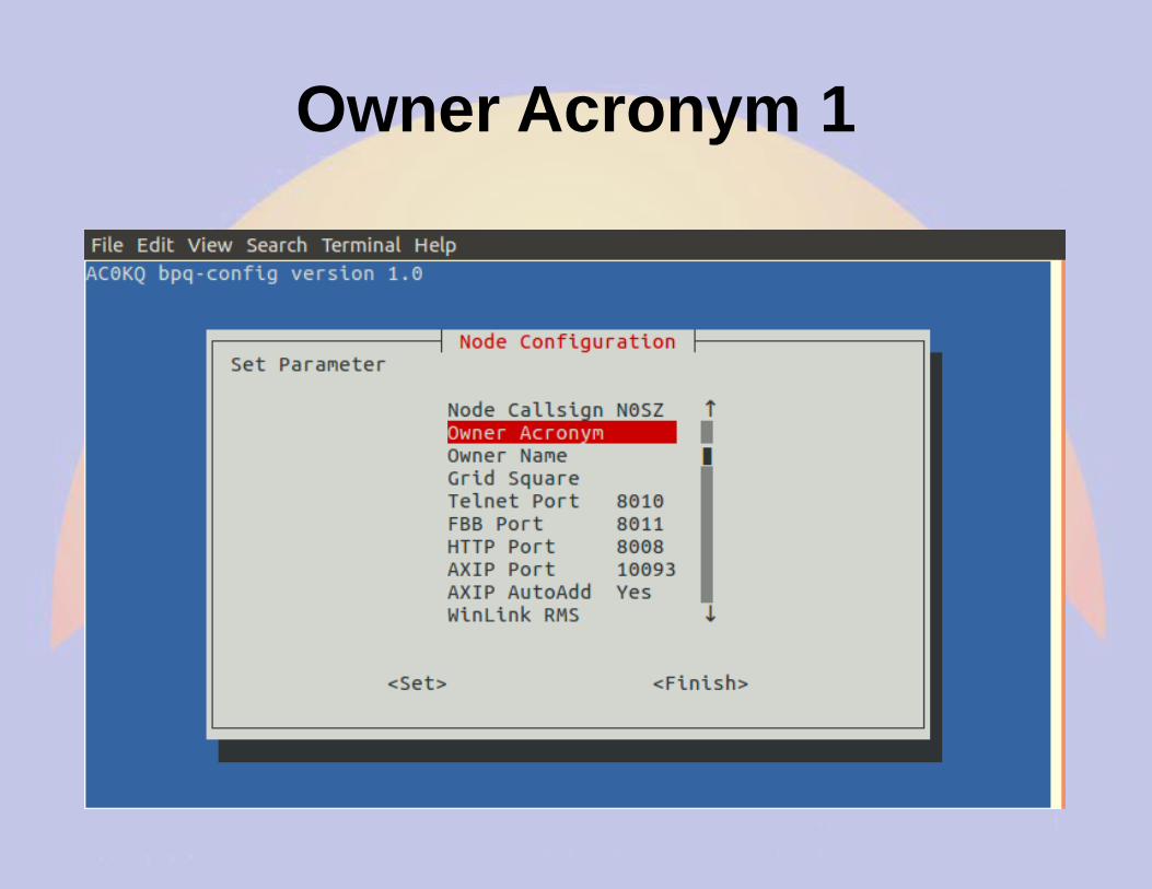
Owner Acronym 1
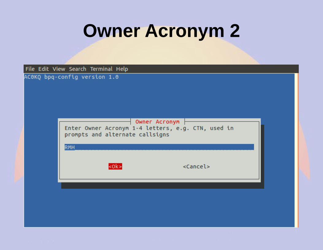
Owner Acronym 2
Owner Name 1
Owner Name 2
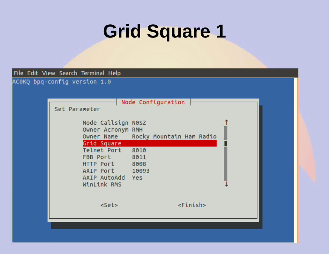
Grid Square 1
Grid Square 2
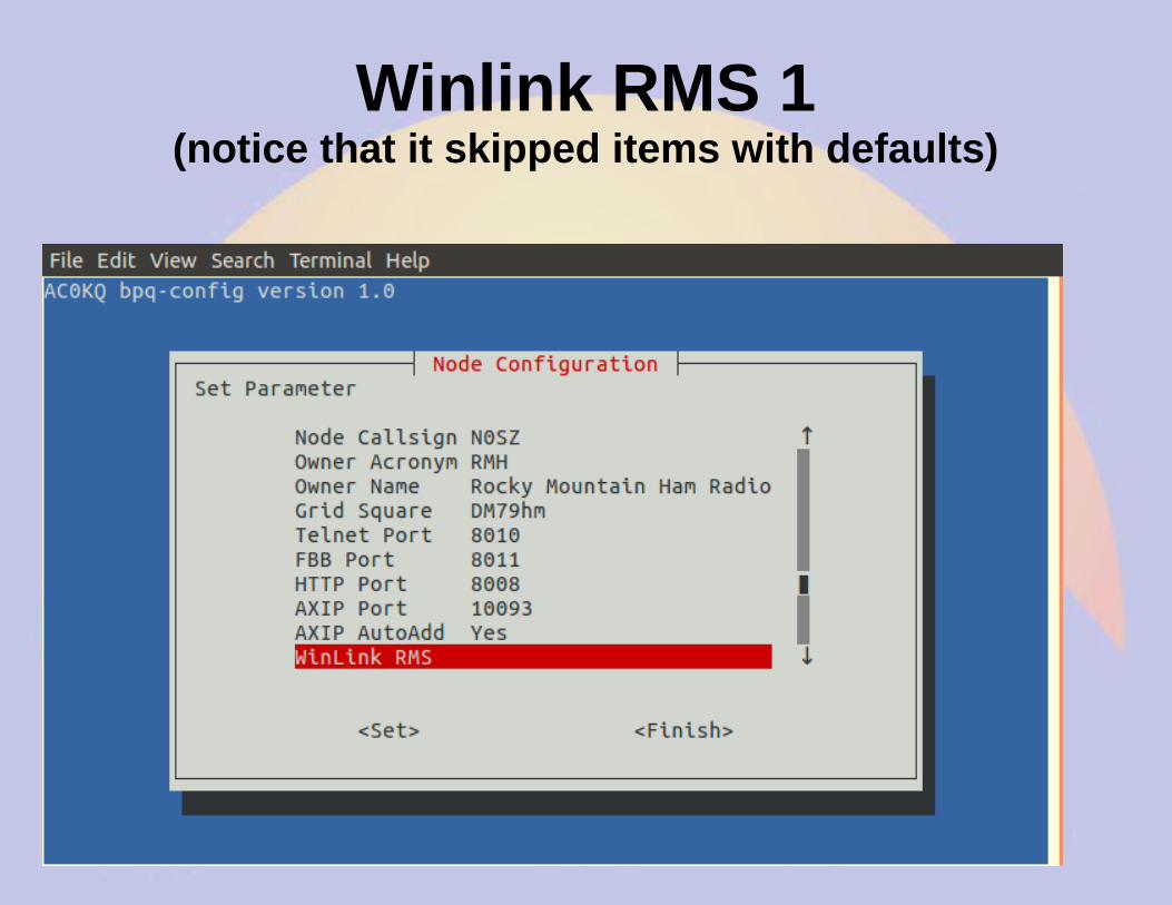
Winlink RMS 1(notice that it skipped items with defaults)
Winlink RMS 2
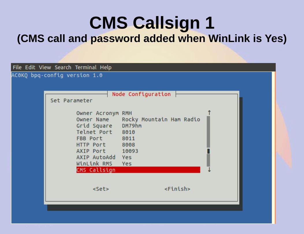
CMS Callsign 1(CMS call and password added when WinLink is Yes)
CMS Callsign 2
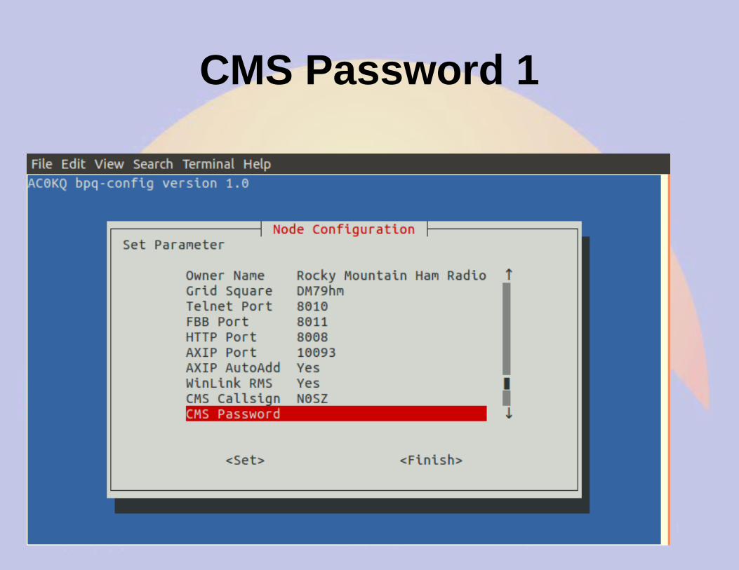
CMS Password 1
CMS Password 2
Chat Server 1
Chat Server 2
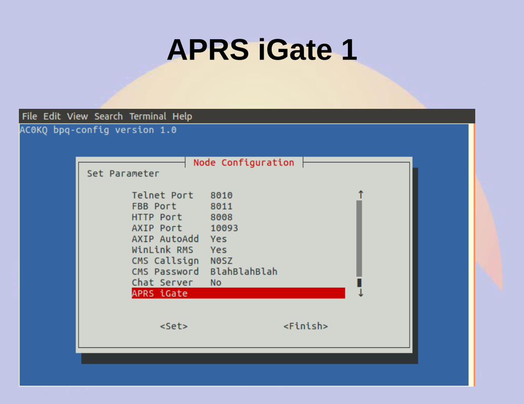
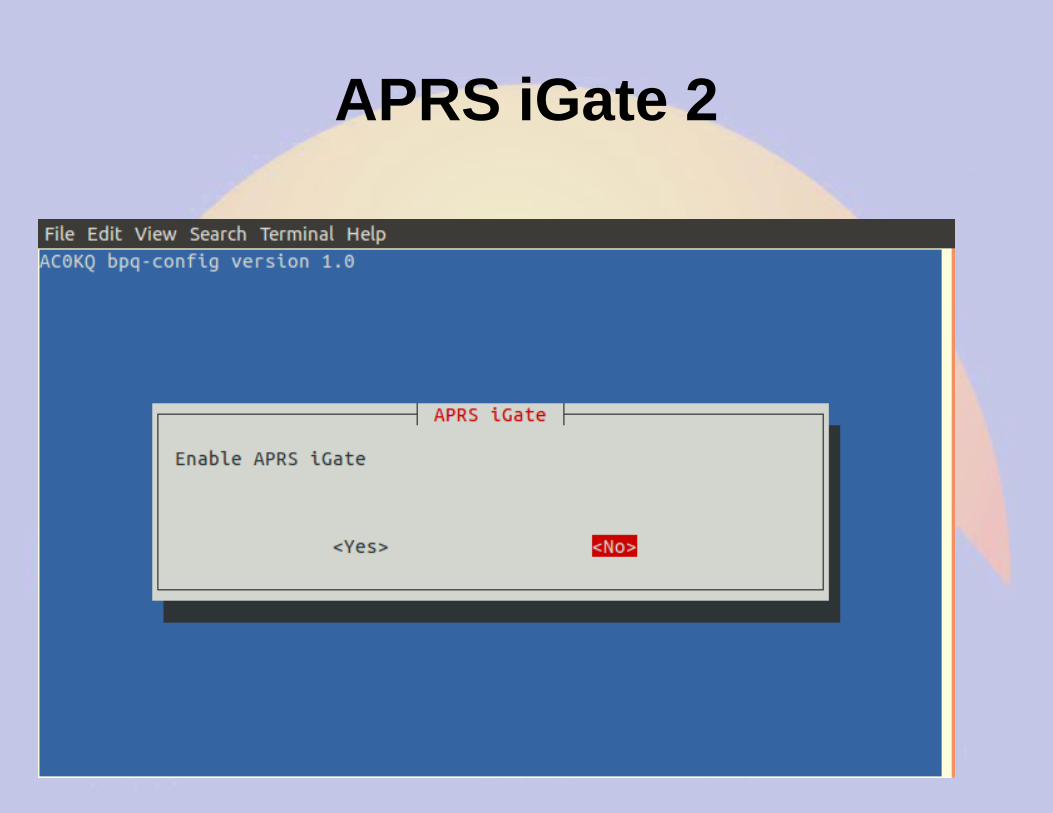
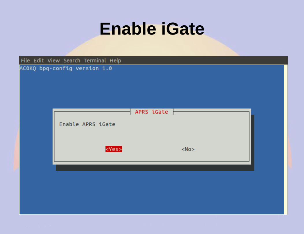
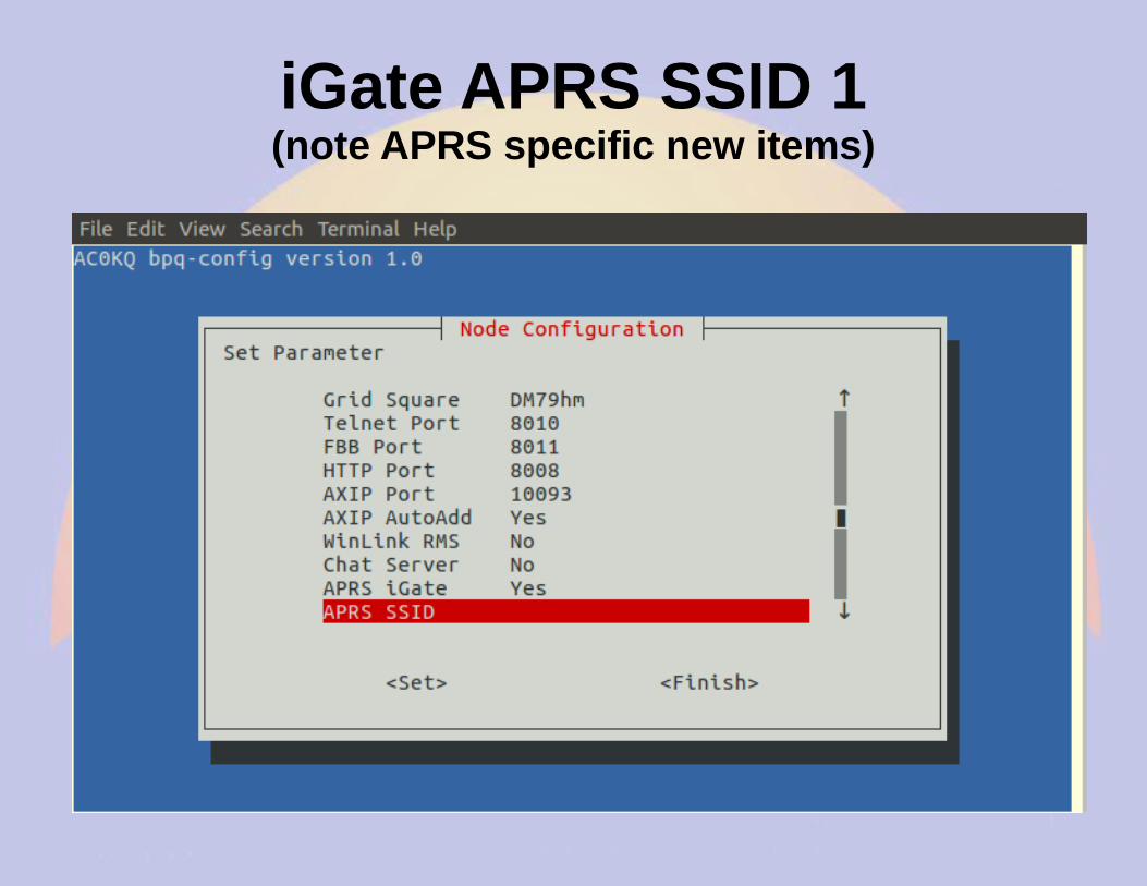
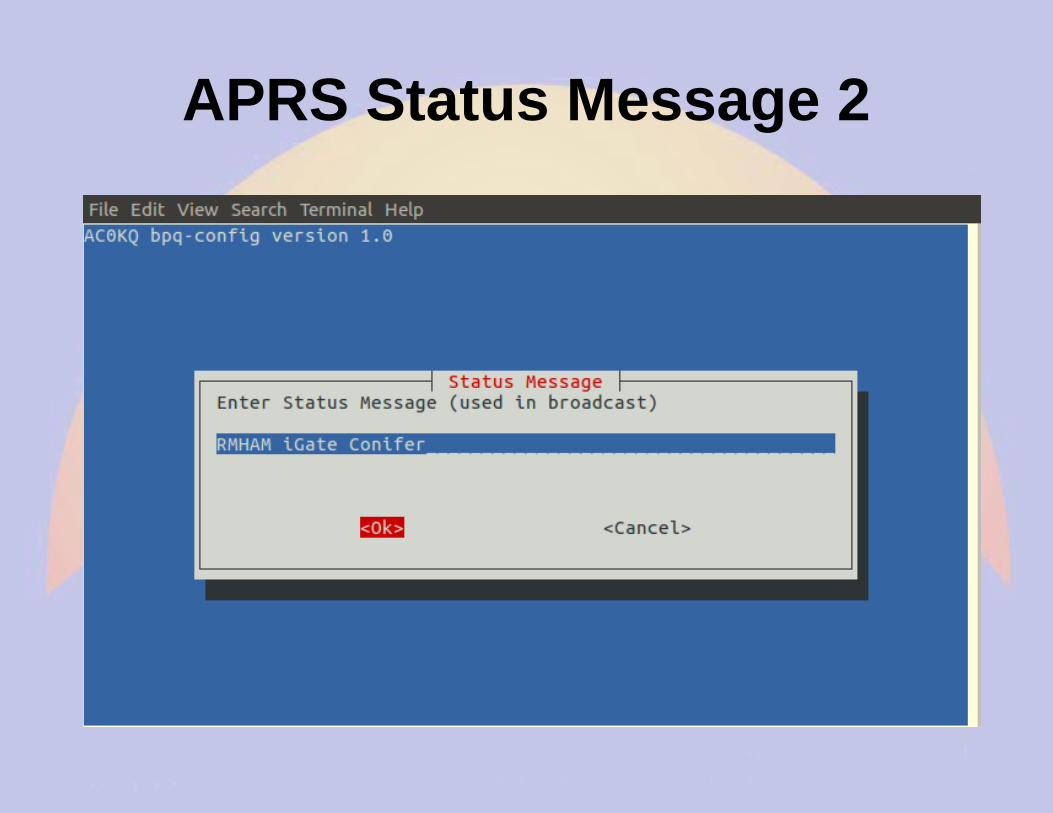
APRS iGate 1
APRS iGate 2
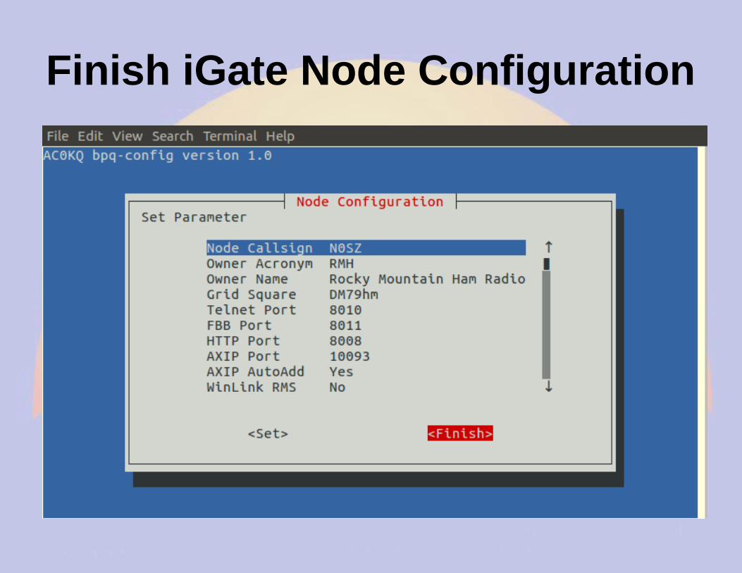
Finish Node Configuration
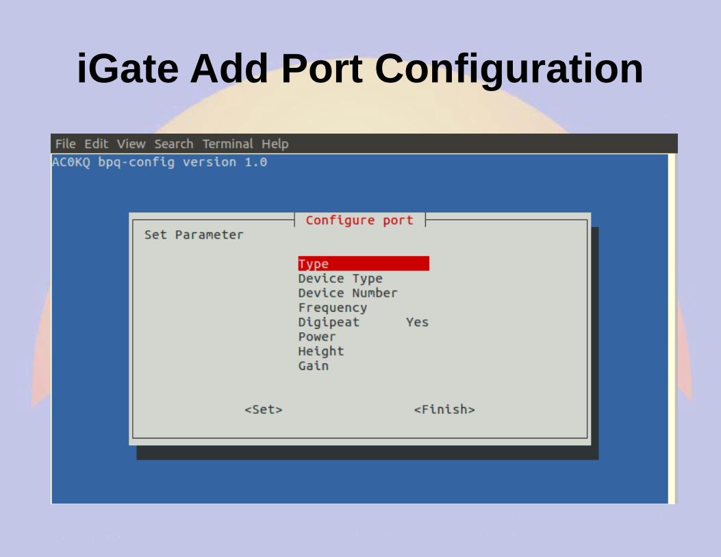
Configure Port
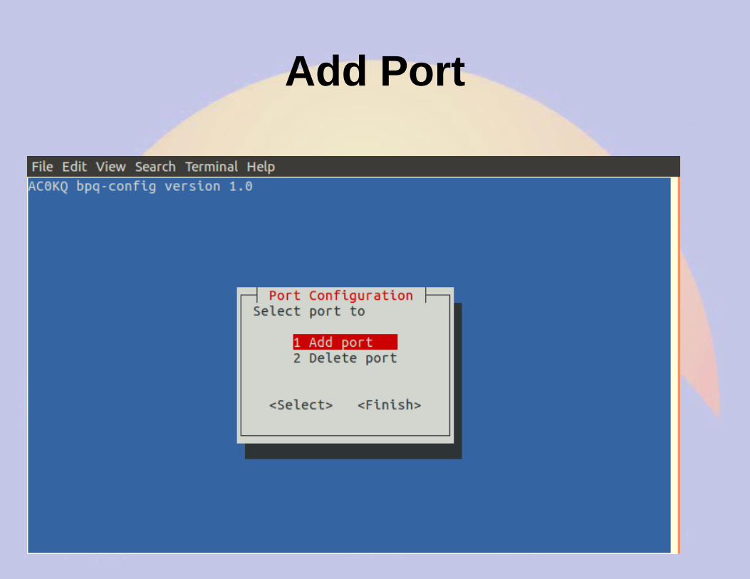
Add Port
Port Type 1
Port Type 2
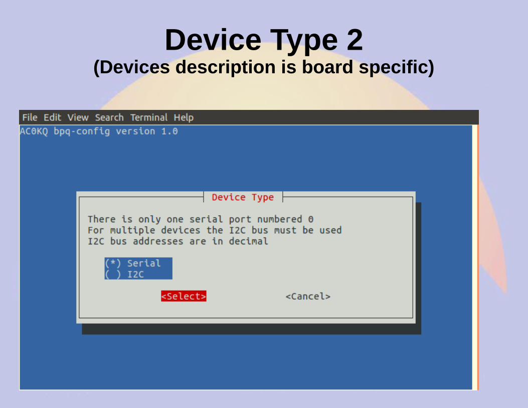
Device Type 1
Device Type 2(Devices description is board specific)
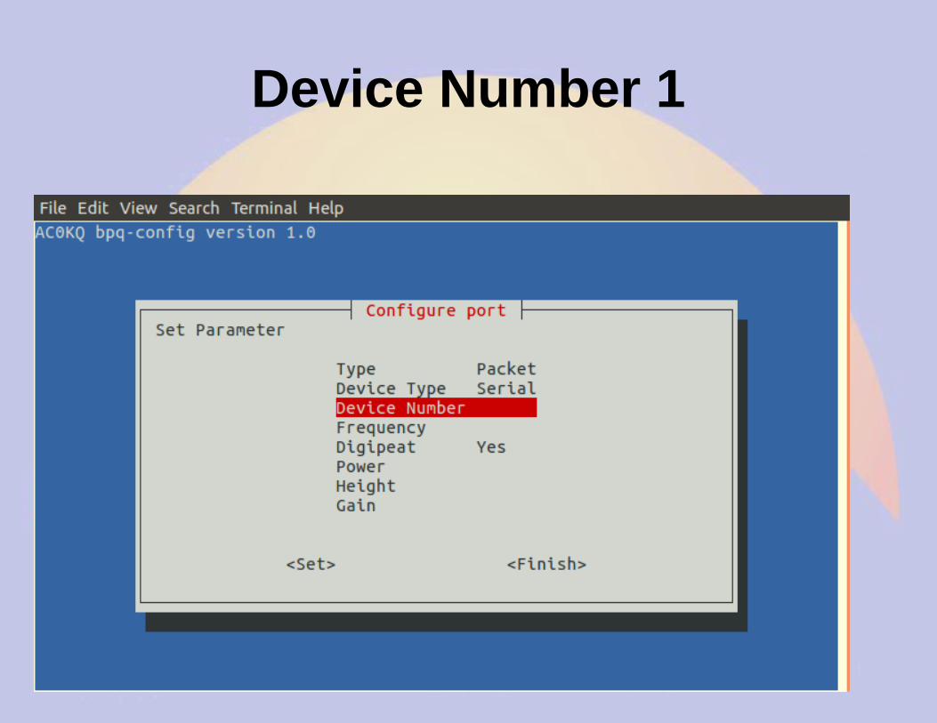
Device Number 1
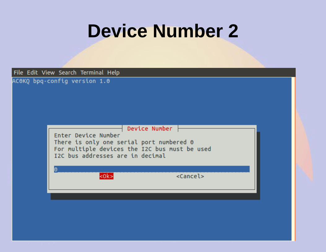
Device Number 2
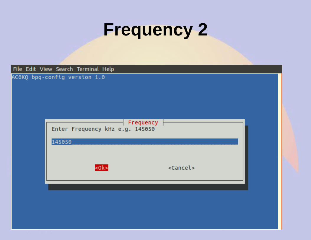
Frequency 1
Frequency 2
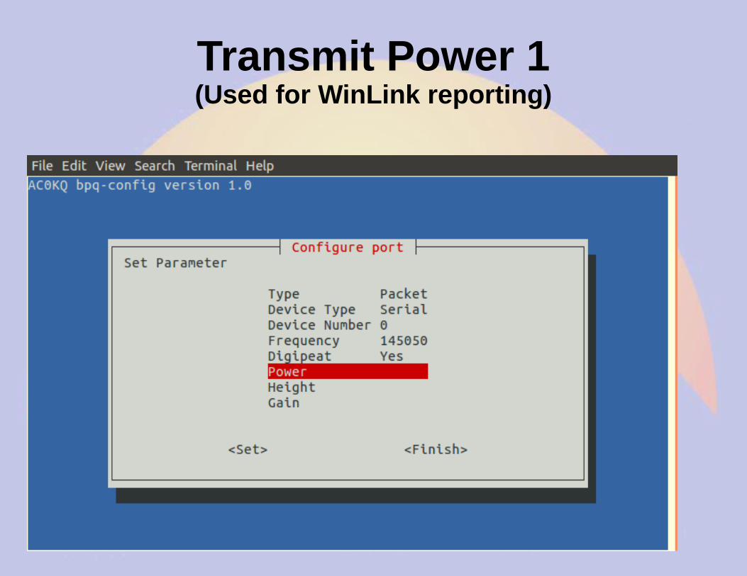
Transmit Power 1(Used for WinLink reporting)
Transmit Power 2
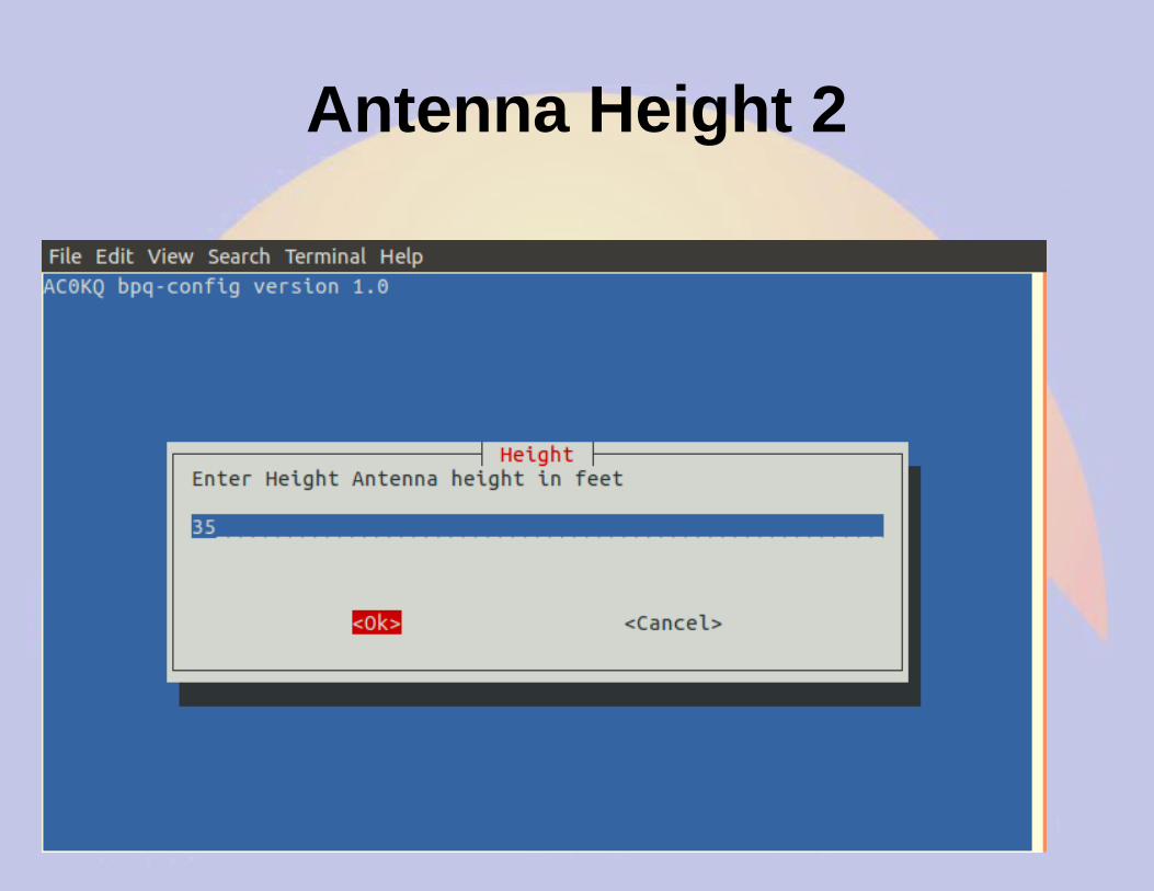
Antenna Height 1(Used for WinLink reporting)
Antenna Height 2
Antenna Gain 1(Used for WinLink reporting)
Antenna Gain 2
Finish Port Configuration
Finish Adding Ports
Add Telnet (IP) Users(You mast have at least one)
Add new Telnet user
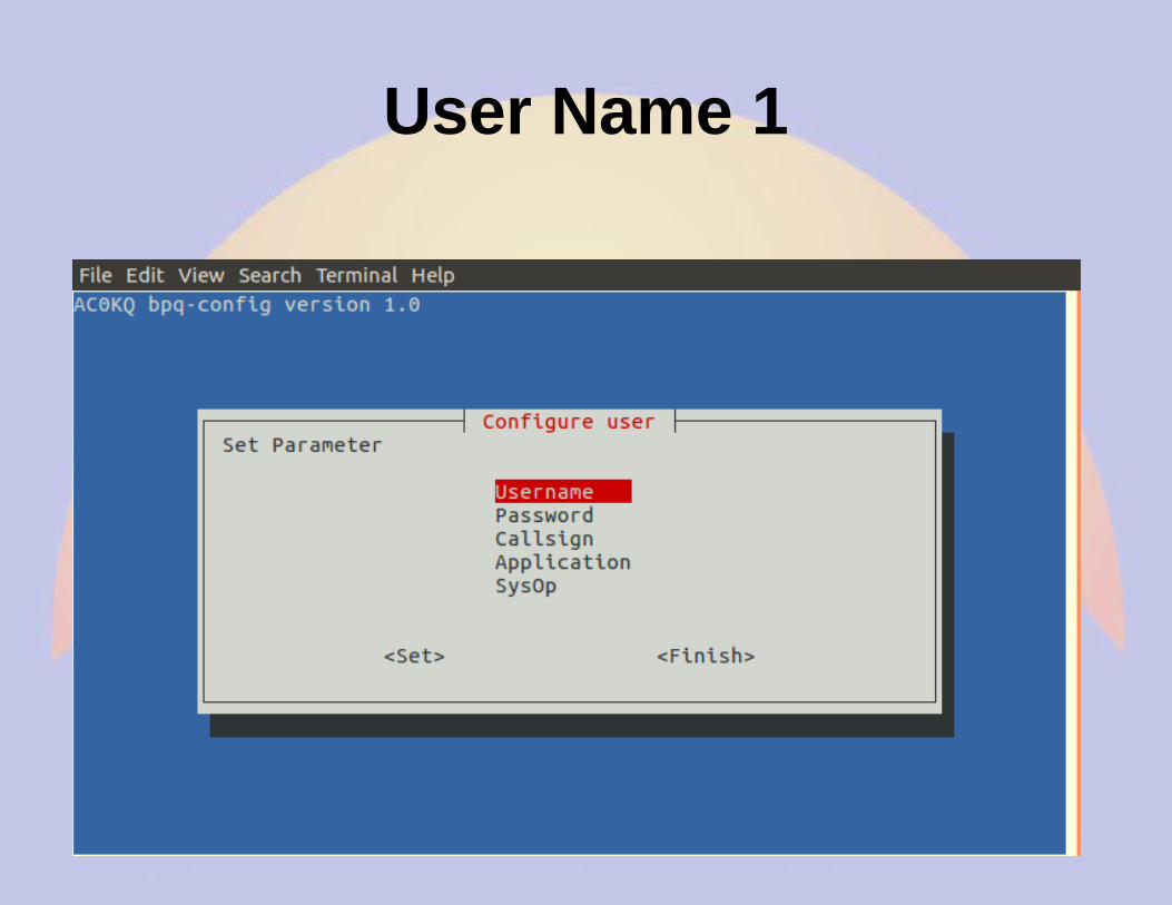
User Name 1
User Name 2
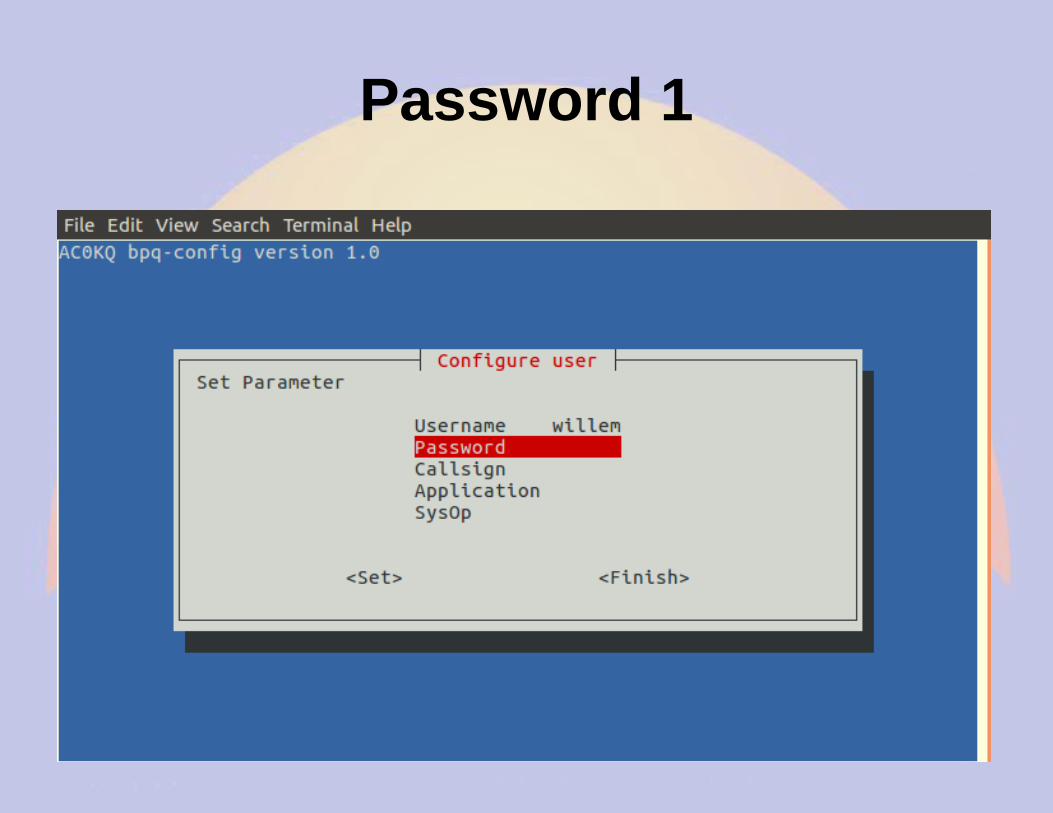
Password 1
Password 2
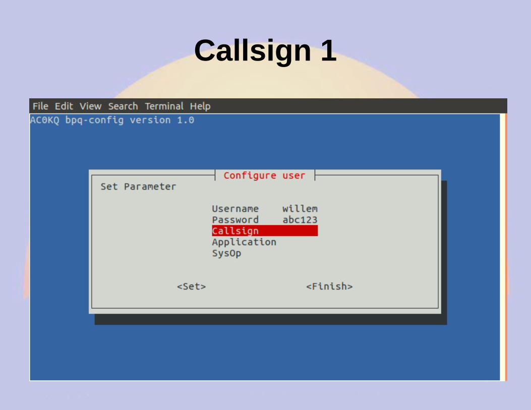
Callsign 1
Callsign 2
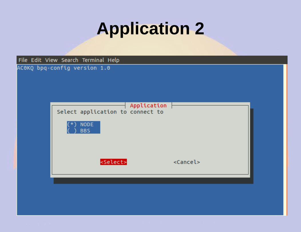
Application 1
Application 2
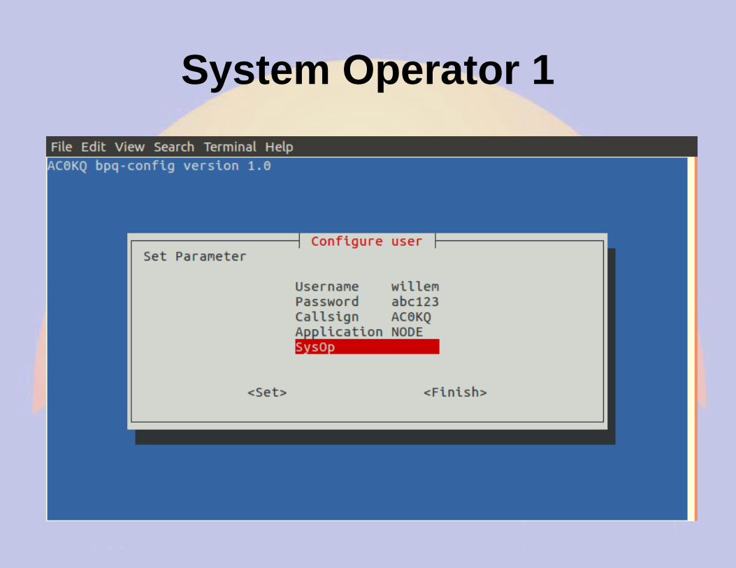
System Operator 1
System Operator 2
Finish User Configuration
Add Another User
Finish adding second user
Finish adding Telnet Users
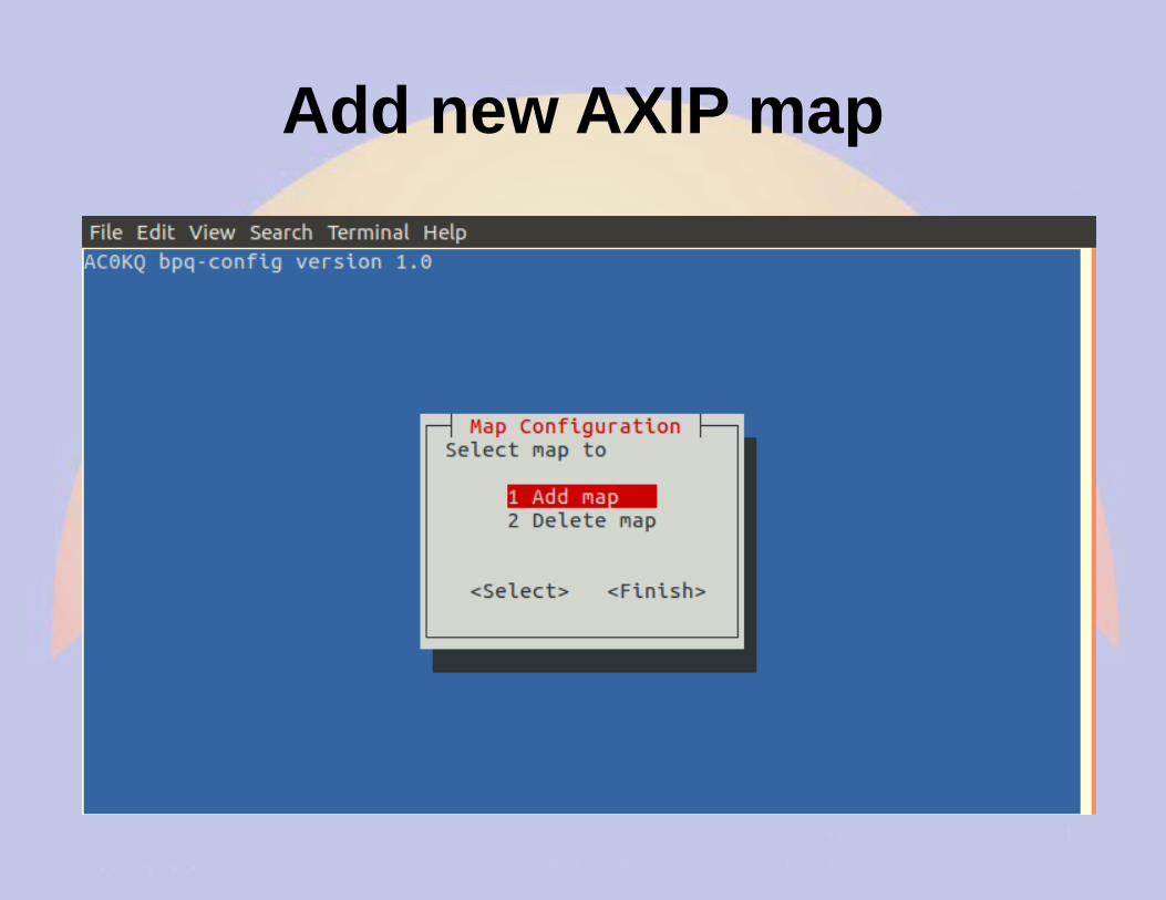
Configure AXIP Node Maps
Add new AXIP map
Callsign 1
Callsign 2
AX IP Address 1
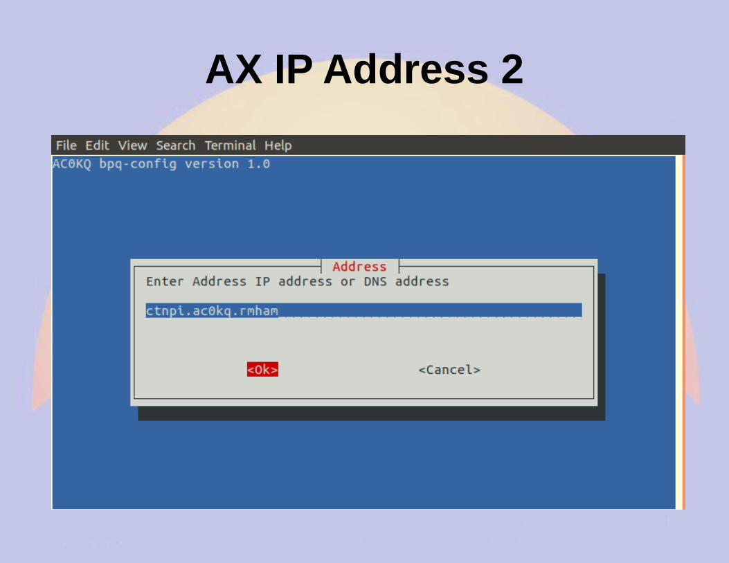
AX IP Address 2
Done Adding AXIP Map
Finish adding AXIP maps
Write BPQ Configuration
Files Written by bpq-config
Done with Configuration
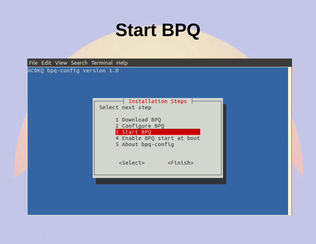
Start BPQ
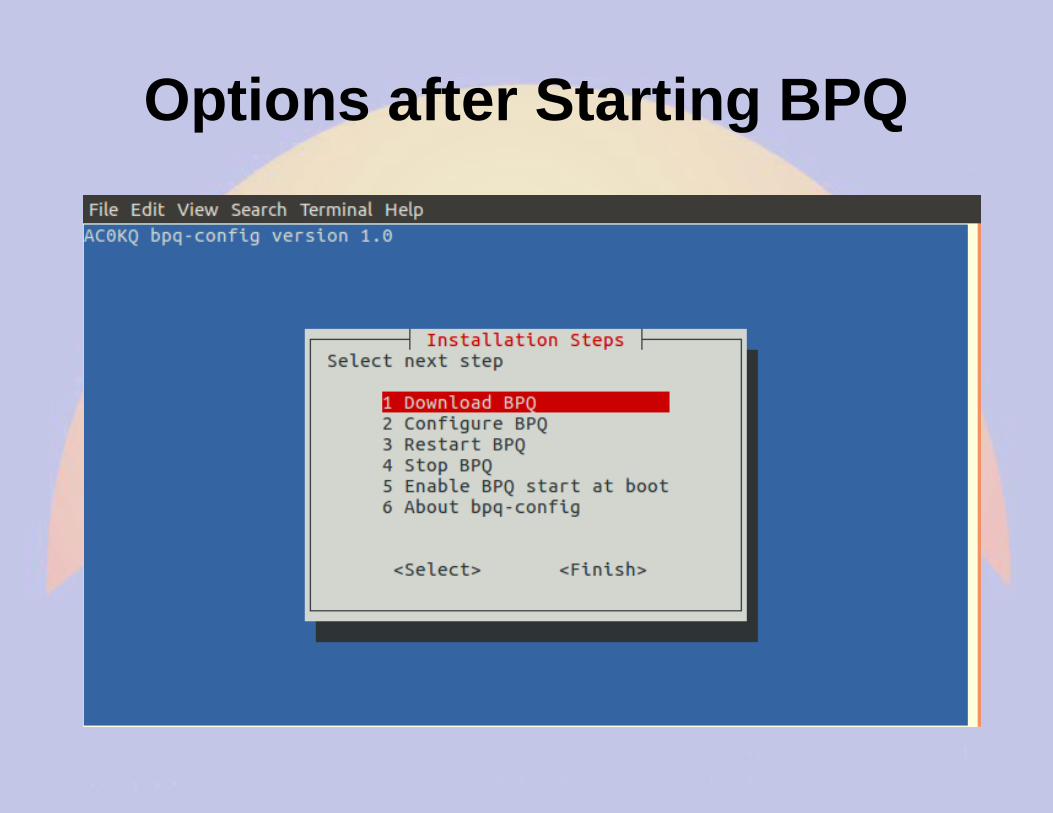
Options after Starting BPQ
Browse to BPQ node port 8008(if you configured a different port, use it instead)
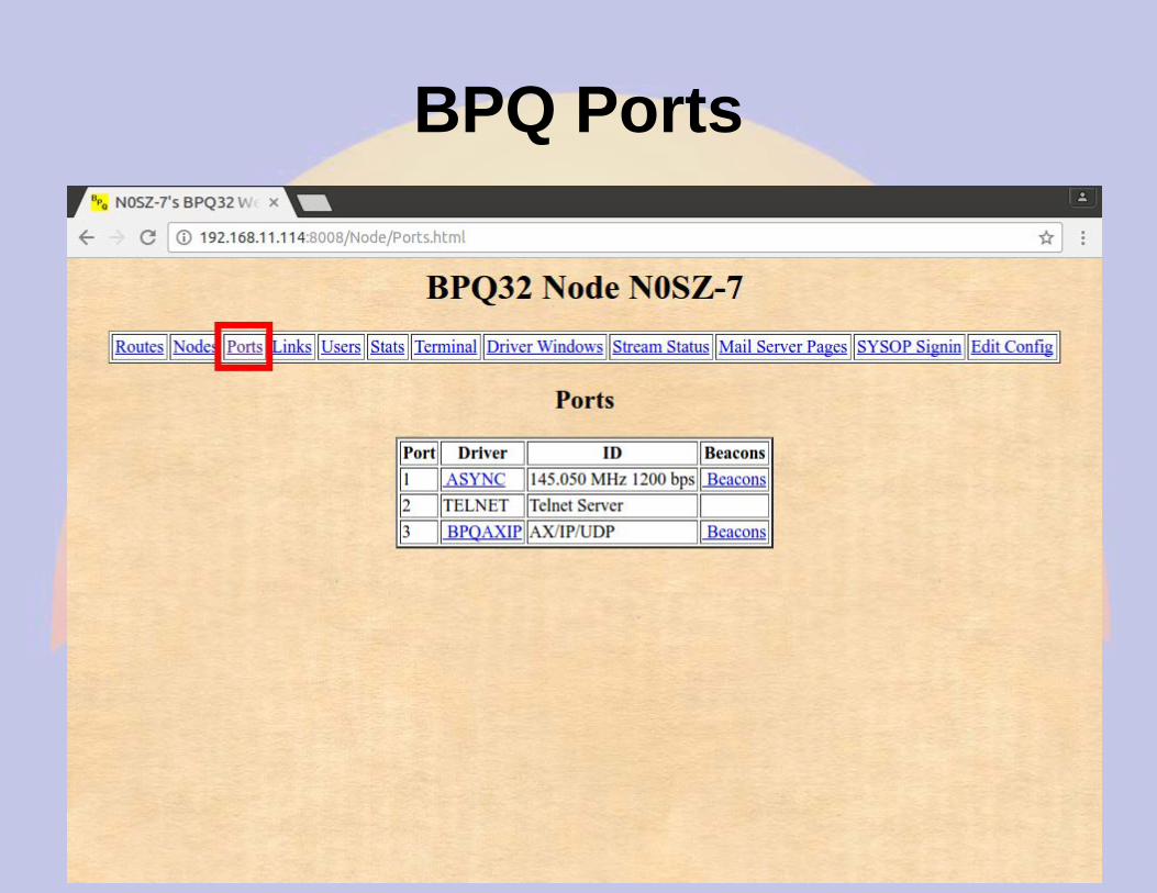
BPQ Ports
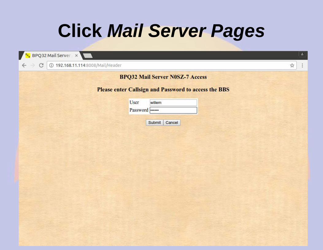
Click Mail Server Pages
BBS Configuration(bpq-config set most of these in linmail.cfg)
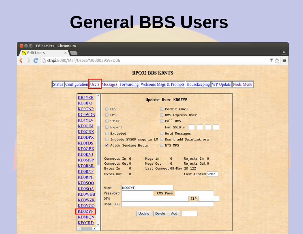
BBS Users(bpq-config added RMS and telnet users)
User RMS is a WinLink2000
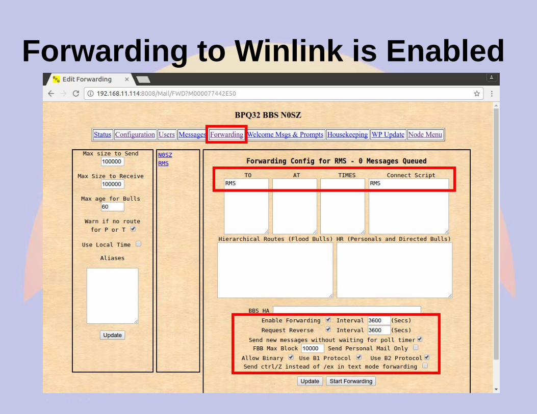
Forwarding to Winlink is Enabled
Housekeeping
Connect out via RF
Connect in via RF (as AC0KQ)
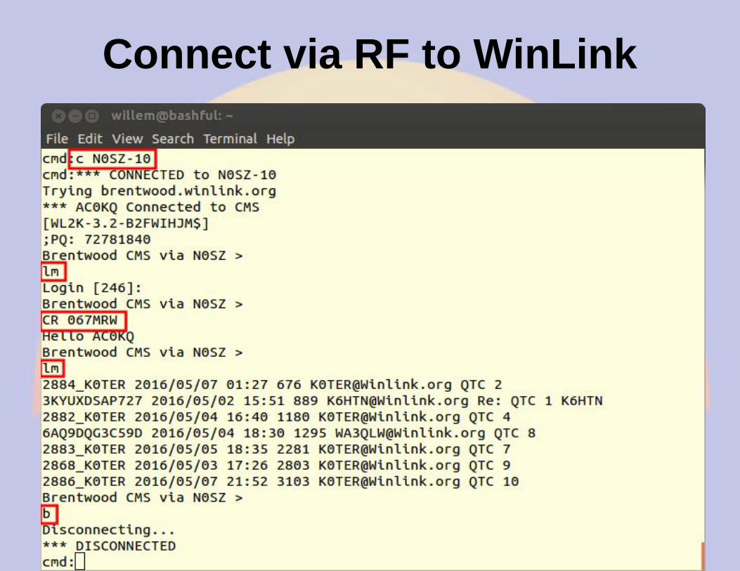
Connect via RF to WinLink
BBS Messages
General BBS Users
WinLink User Download
Forwarding BBS
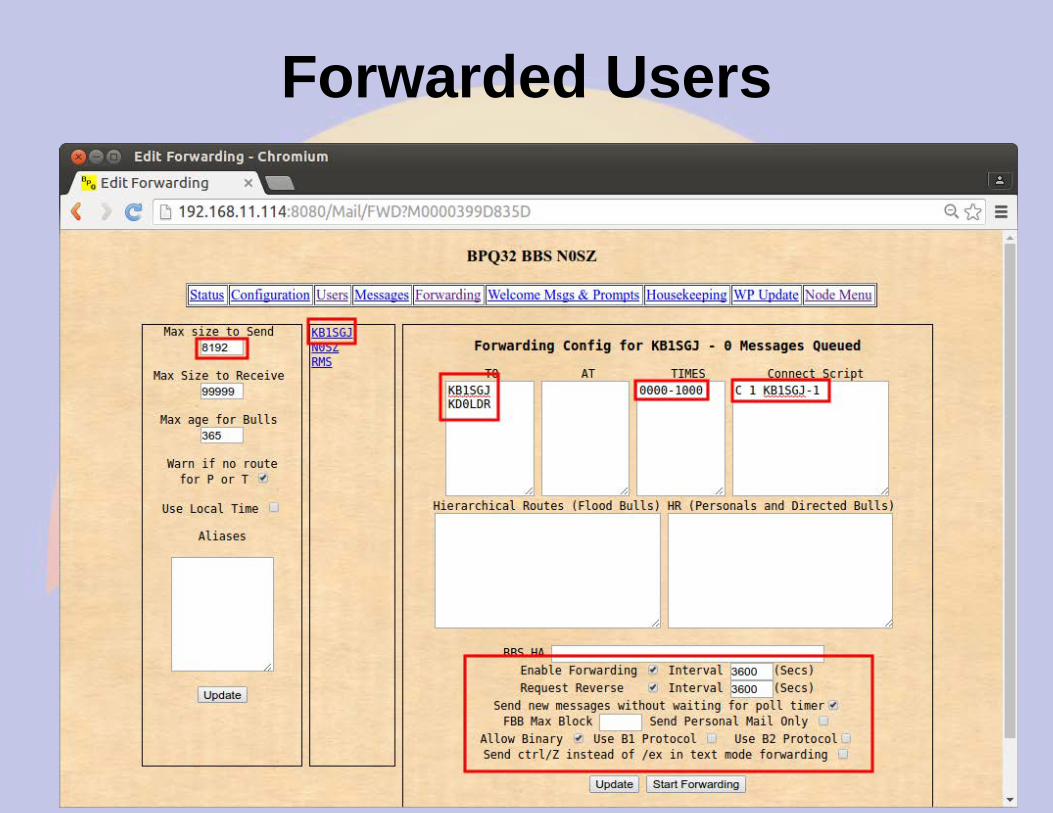
Forwarded Users
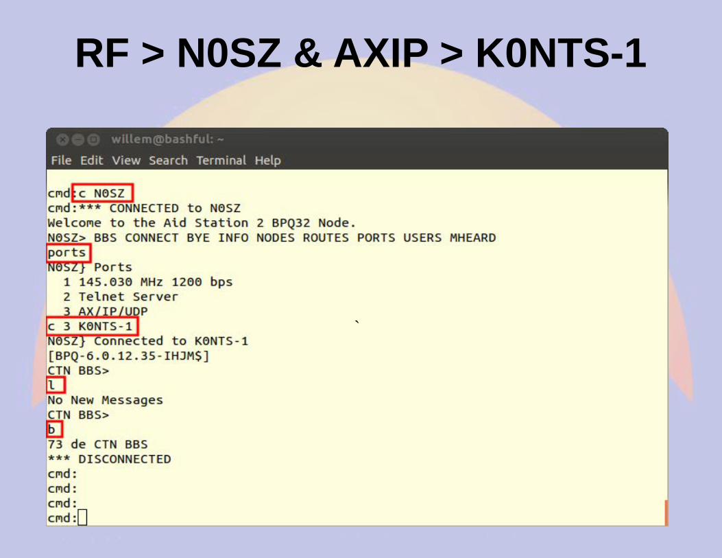
RF > N0SZ & AXIP > K0NTS-1
`
Setting up an iGate
● This iGate setup is on a BeagleBone Black– The only difference with an rPi is the serial
port names in the Port section
● The Node setup is the same as what was done previously– Some but not all the parameters are relevant
● Ports are mapped as Packet or APRS in port configuration– You can have both Packet and APRS ports on
the same BPQ node
Node Configuration(Note that Winlink RMS and Chat is NO)
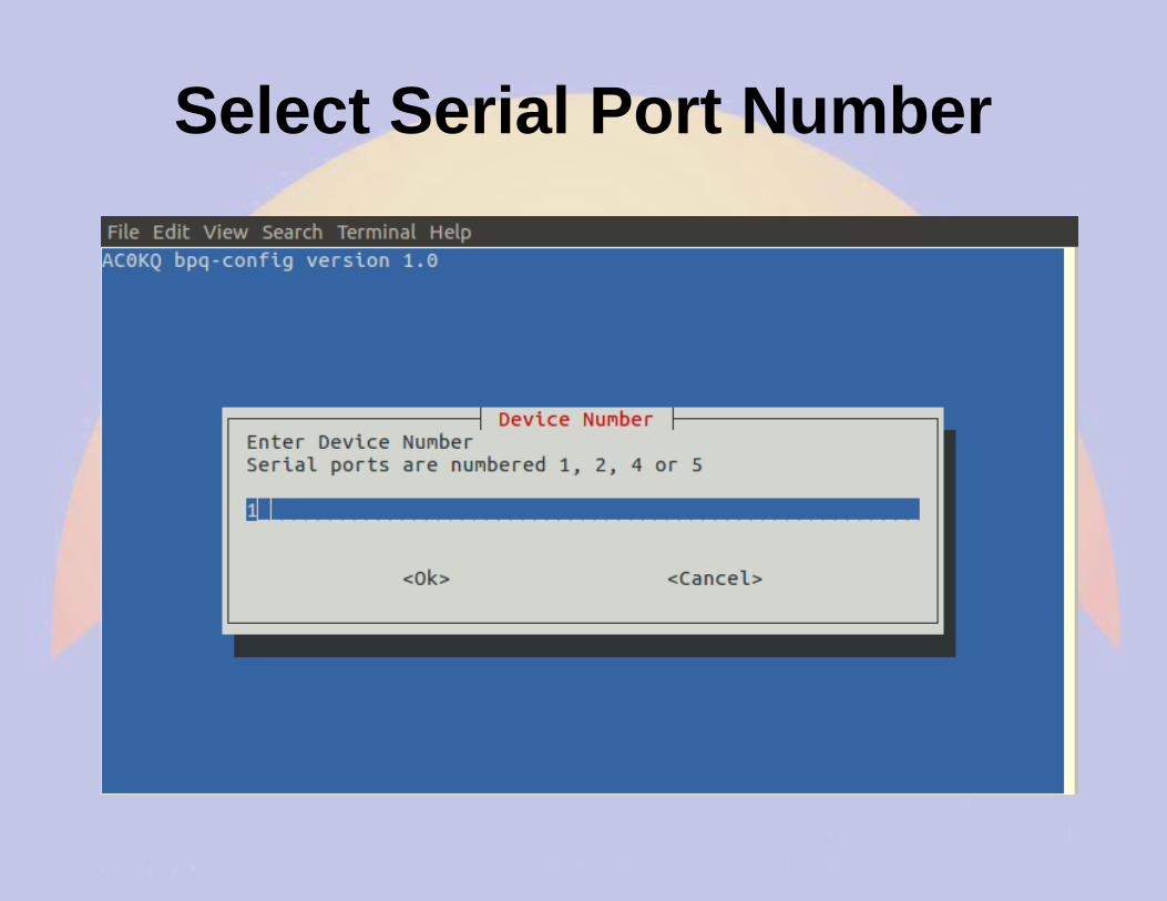
Set Serial Port(Note that this is a Beaglebone so 4 ports)
Select Serial Port Number
Select Serial Port Number
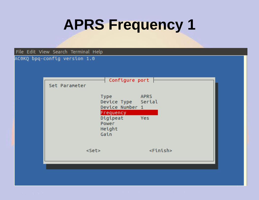
APRS Frequency 1
APRS Frequency 2
Finish Port Configuration
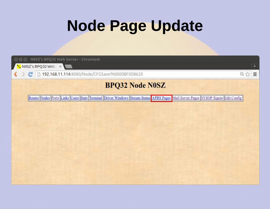
Node Page Update
APRS Main Page
APRS RF Stations
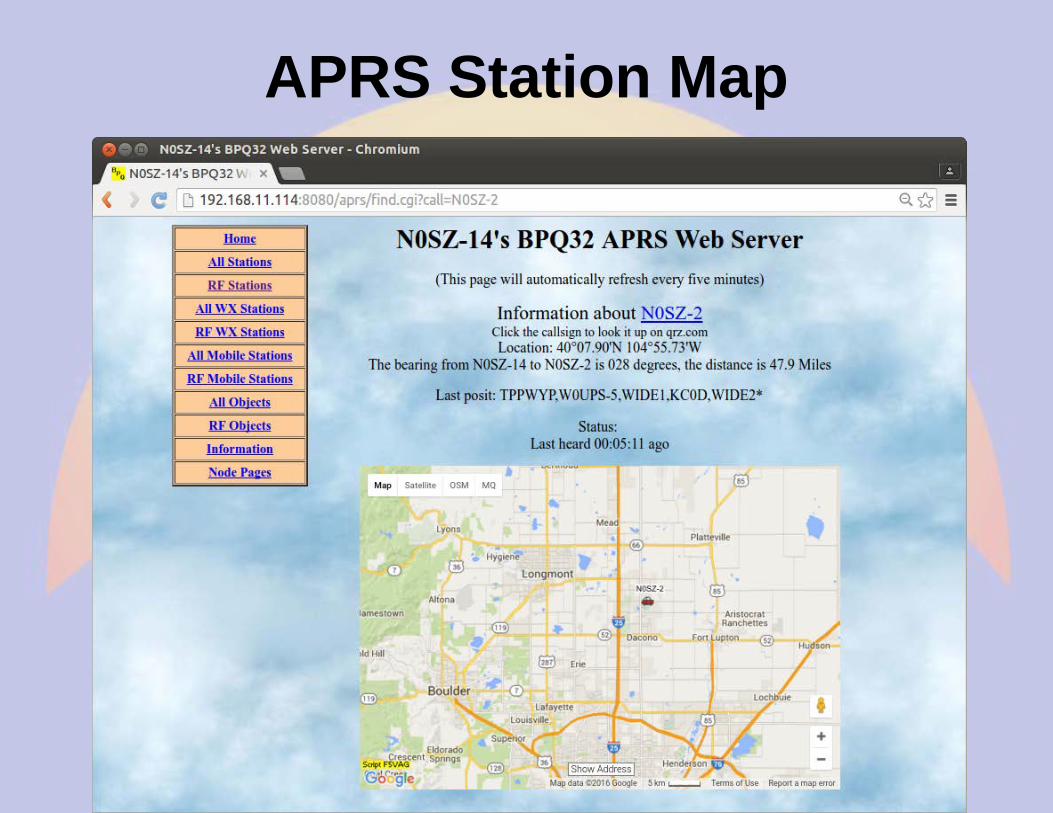
APRS Station Map
Report on aprs.fi
Data graph on aprs.fi
Adding device ports
● Beaglebone has 5 serial ports– Stack 4 TNC-Blacks
– Attach external devices via headers
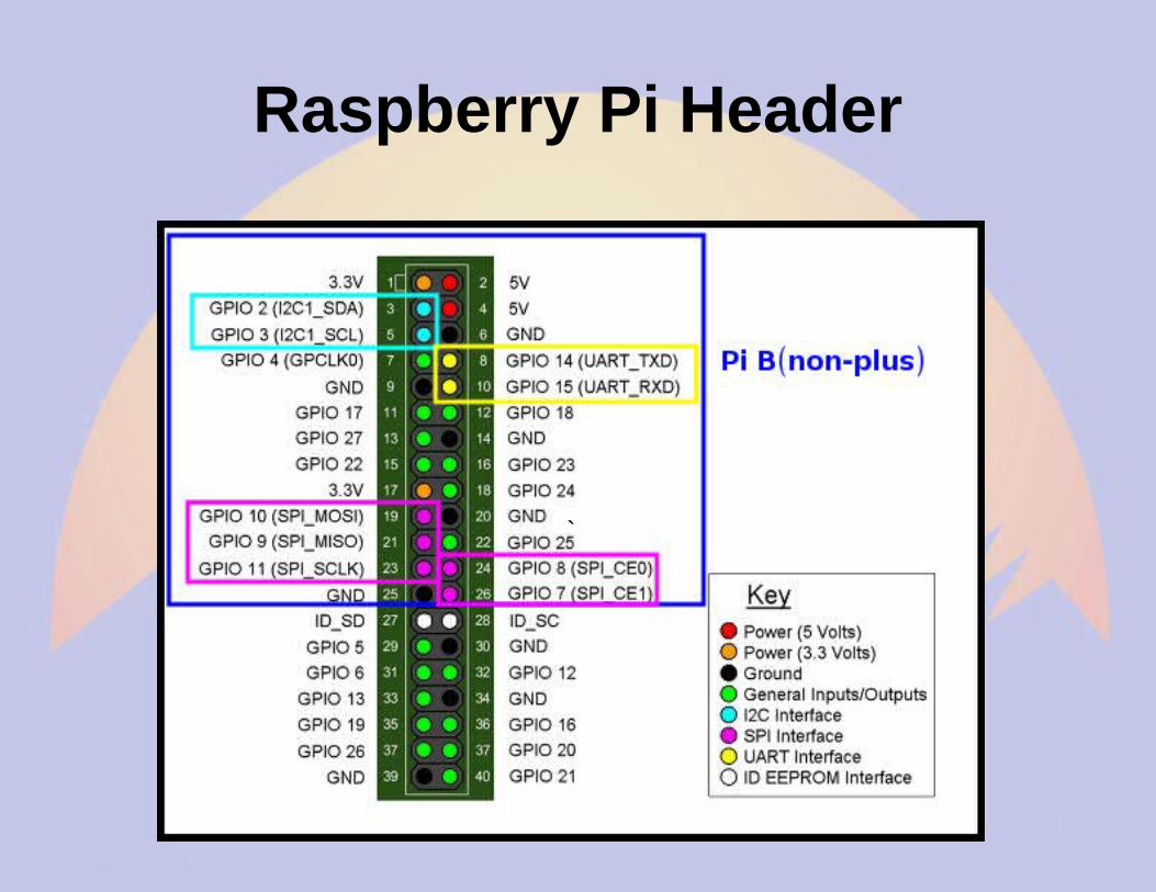
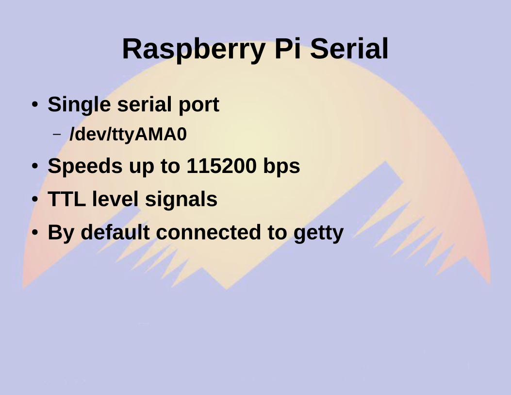
● Raspberry Pi has 1 serial port– Access TNC-Pi via I2C bus
– Requires reprogramming of TNC-Pi
Reprogramming TNC
● Disable BPQ to have exclusive access to the TNC device– systemctl disable bpq.service
– systemctl stop bpq.service
● Turn off power between steps● Enable BPQ when done
– systemctl enable bpq.service
– systemctl start bpq.service
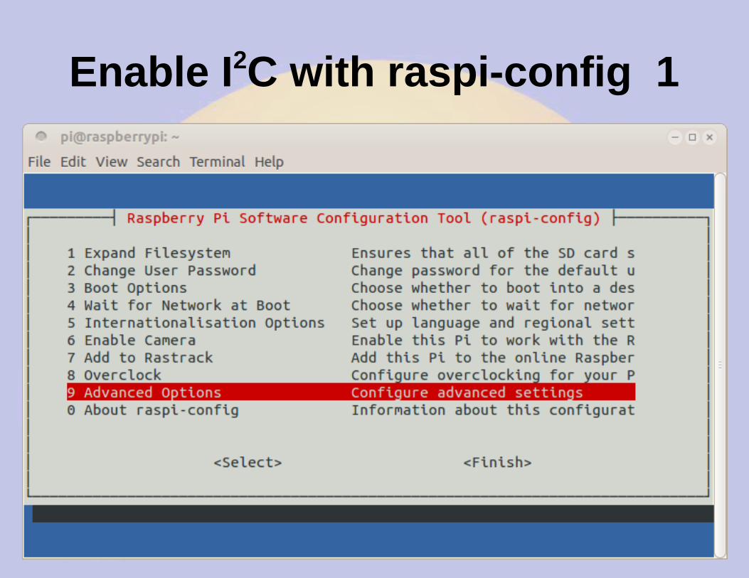
Enable I2C kernel modules
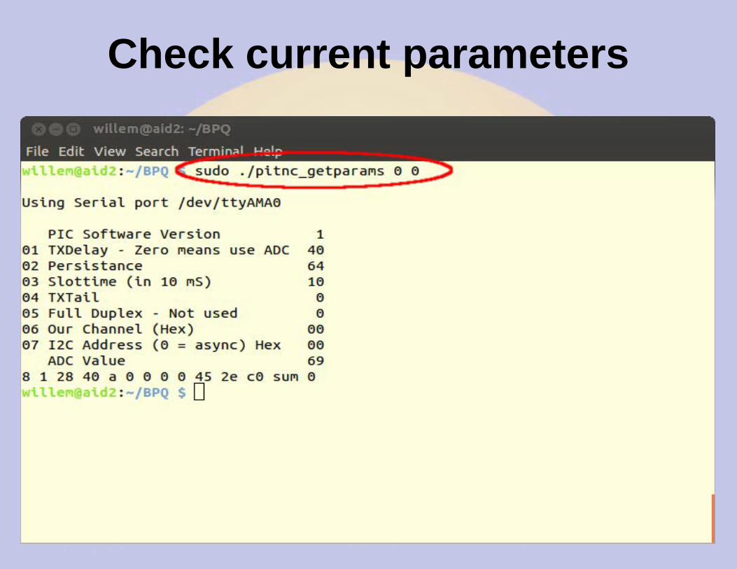
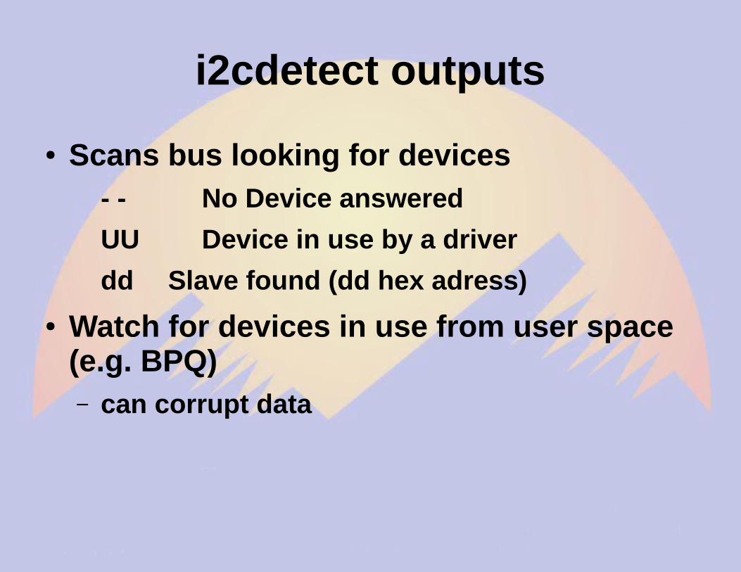
Check current parameters
Set I2C address to 16 (0x10)
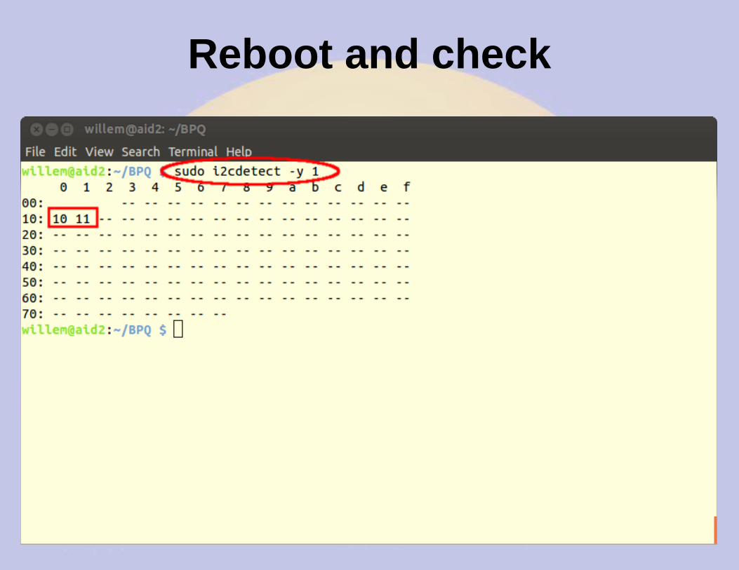
Power off&on and check
Check parameters
Adding a Second RF Port
● Must use I2C since rPi has only one serial port
● Convert first TNC to I2C before mounting second TNC
● Test it to make sure it works● Add second TNC● Power down between steps
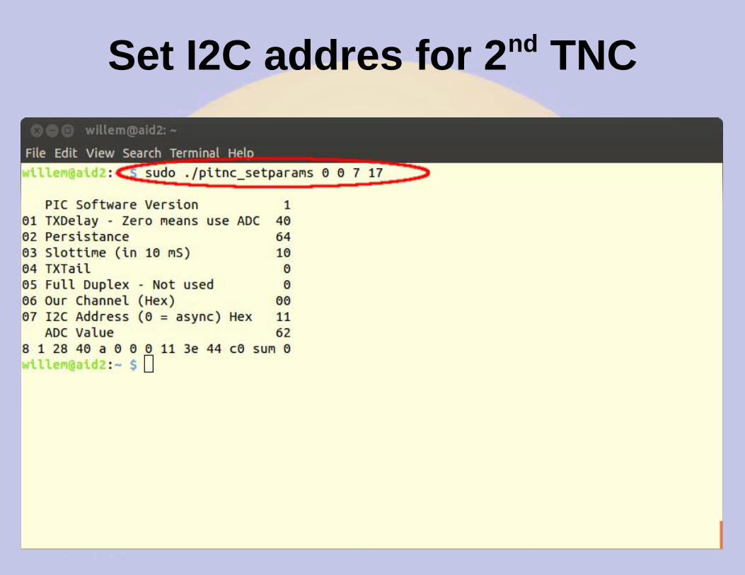
Set I2C addres for 2nd TNC
Reboot and check
BPQ Port 1
Port 1 is for BBS/RMS
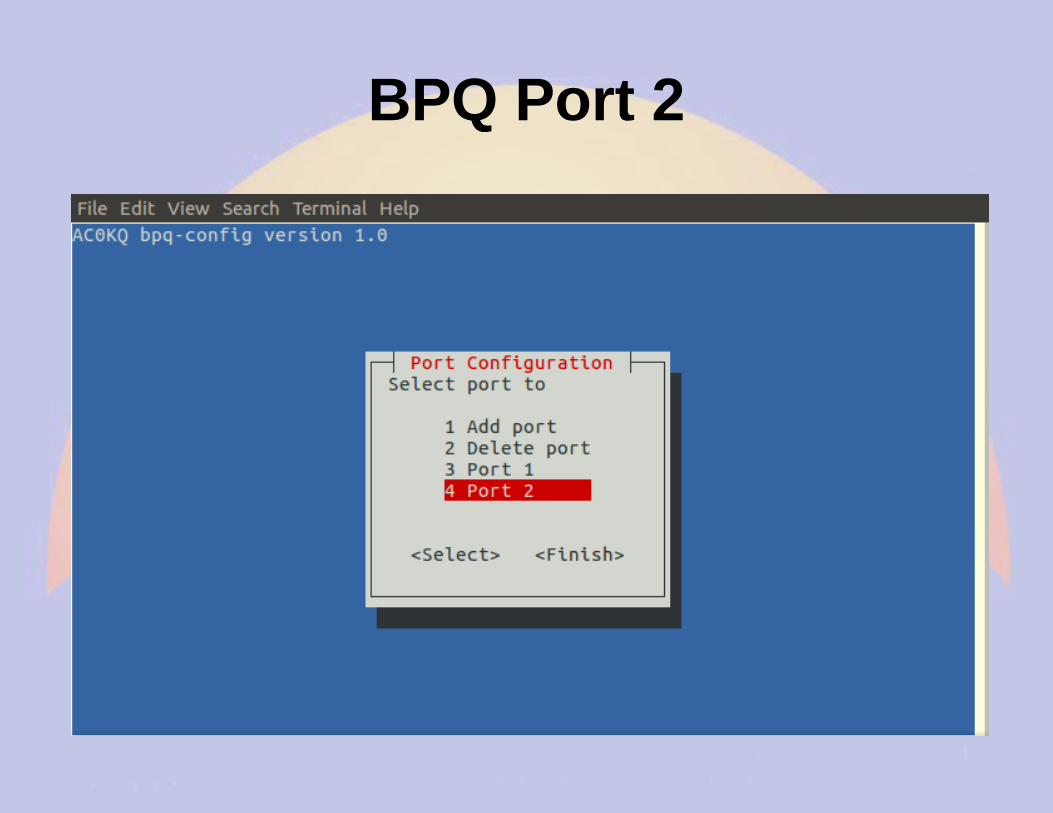
BPQ Port 2
Port 2 is for APRS
BPQ Ports Page
Advanced Configuration
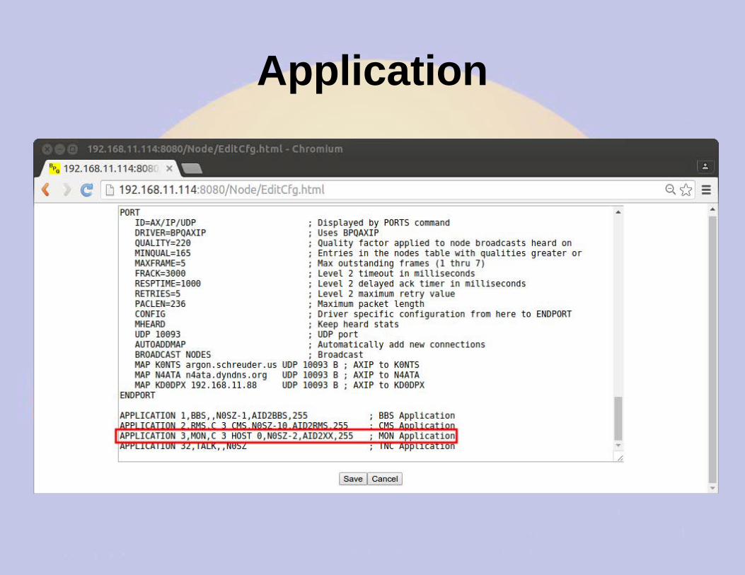
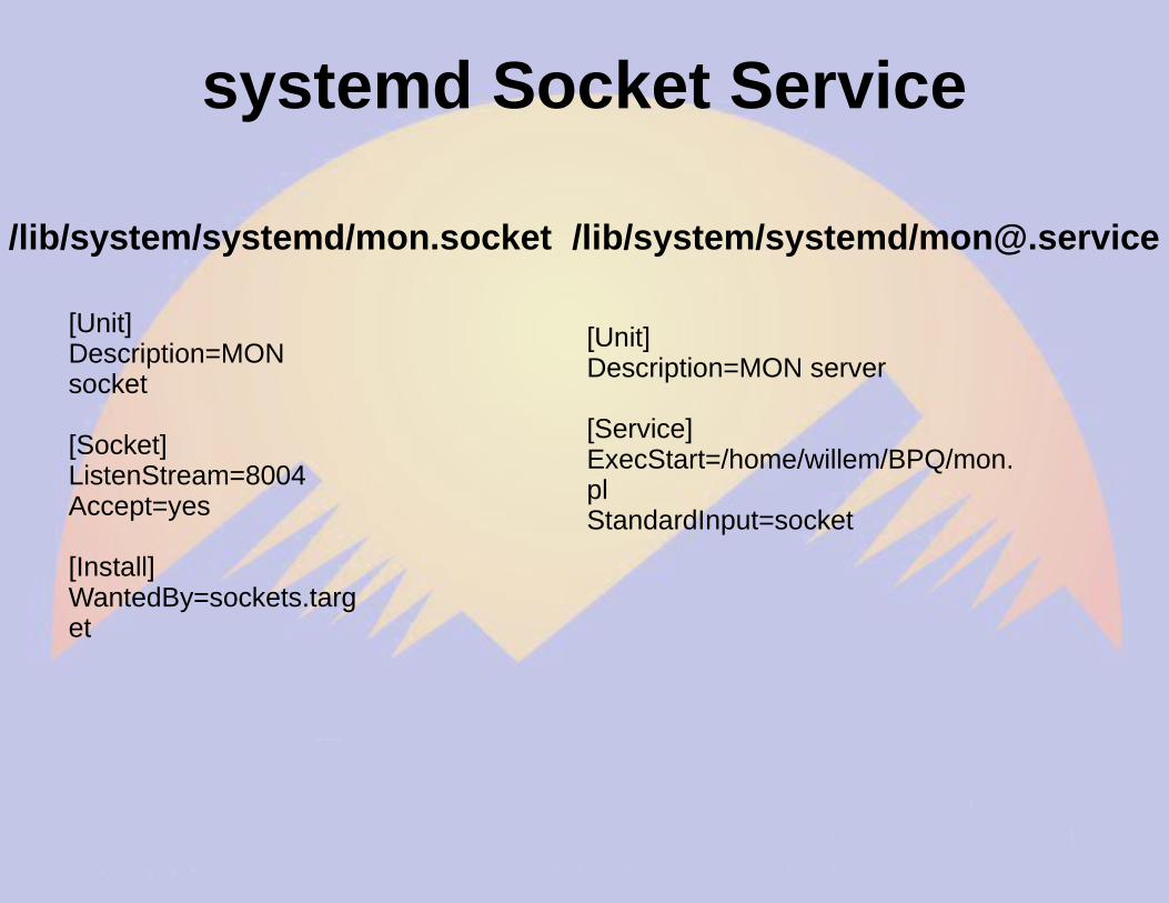
Adding a new service
● BPQ adds new services via TCP/IP● BPQ connects to local port● Received stream piped to stdin● Transmits output from stdout● First line is connected station call
Monitor service
● Written in Perl● Interprets commands● Used to get system time and disk● Bye to exit● Mapped to N0SZ-2 and port 8004
for i in range(0,8): # Snarf file fd = open("/sys/devices/ocp.3/helper.16/AIN%d" % i) text = fd.read() fd.close() # Decode voltage V = float(text)/1000 # Print voltage print "AIN%d = %5.3fV" % (i,V)
# Snarf the slave list filefd=open("/sys/bus/w1/devices/w1_bus_master1/w1_master_slaves")text = fd.read()fd.close()# Split text on line breaksslaves = filter(None,text.split("\n"))# Sort so that order is predictableslaves.sort()
Reading Temps in Python 2# Blank dictionarytemps = {}# Loop over devicesfor slave in slaves: if slave=="": continue # Snarf device file fd = open("/sys/bus/w1/devices/"+slave+"/w1_slave") text = fd.read() fd.close() # Split lines lines = text.split("\n") words = lines[1].split(" ") # Get temperature C = float(words[9][2:])/1000 F = 9*C/5+32 # Add result to dictionary temps[slave] = "%.1fF" % F
Observations
● Temperature conversion occurs when you cat the file– About 700mS per device
● Temperature reads are best done using a separate thread
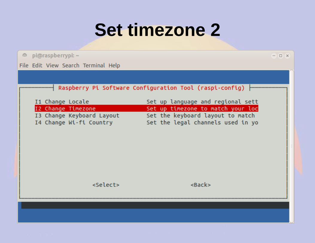
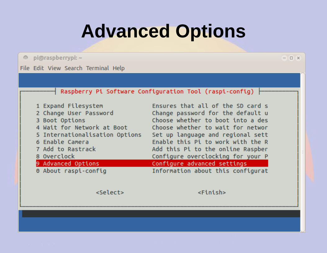
● rPi 1wire support in raspi-config
Part 5 Software Defined Receiver
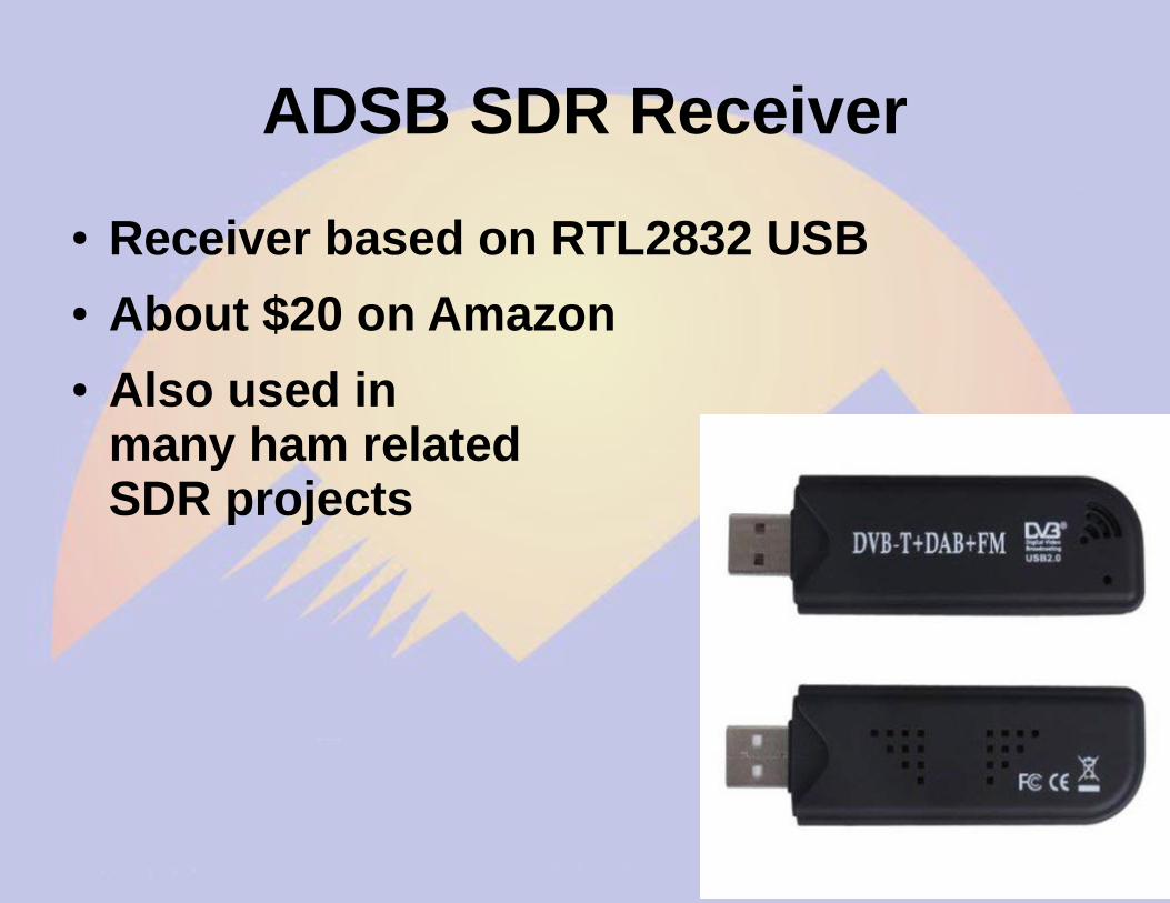
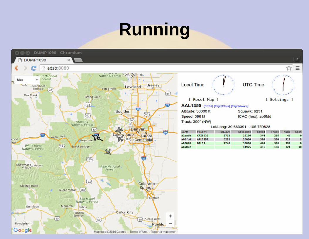
ADSB SDR Receiver
● Receiver based on RTL2832 USB● About $20 on Amazon● Also used in