Simon Bott, Farhat Beg Application of pulsed power driven plasmas to study astrophysical jets and supersonic outflows Simon Bott, Farhat Beg University of California, San Diego Sergey Lebedev, Jerry Chittenden Imperial College London, UK Presented at the first U.S. Plasma Jet Workshop, which was sponsored by the DOE Office of Fusion Energy Sciences and held at Los Alamos National Laboratory on January 24-25, 2008
Transcript
Simon Bott, Farhat Beg
Application of pulsed power driven plasmas to study
astrophysical jets and supersonic outflows
Simon Bott, Farhat Beg
University of California, San Diego
Sergey Lebedev, Jerry Chittenden
Imperial College London, UK
Presented at the first U.S. Plasma Jet Workshop, which was sponsored by the
DOE Office of Fusion Energy Sciences and held at Los Alamos National
Laboratory on January 24-25, 2008
Ablating wires
Introduction
2
0IdmVabl
µ−=
• Mass ablation rate described by Rocket model (S.Ledebev, Phys Plasmas, 8, p3734, (2001)) 16mm
04 RdtVabl
π−=
• Mass ablated determined by Imax
• Timescale determined by τ
Ge
nera
tor
Dri
ve C
urr
ent
/ M
A
IMAX
abl
Time-slice from 3D Resistive MHD Gorgon Code (J.Chittenden, Plasma Phys Control Fusion 46, B457 (2004)
0 50 100 150 200 250 300 350
Ge
nera
tor
Dri
ve C
urr
ent
/ M
A
Time/ nsτ
Generator Location Imax ττττMAGPIE Imperial College 1MA (2MA) 250nsGenASIS UCSD 0.25 MA 150ns
X-Pinch Driver UCSD 0.08 MA 50ns
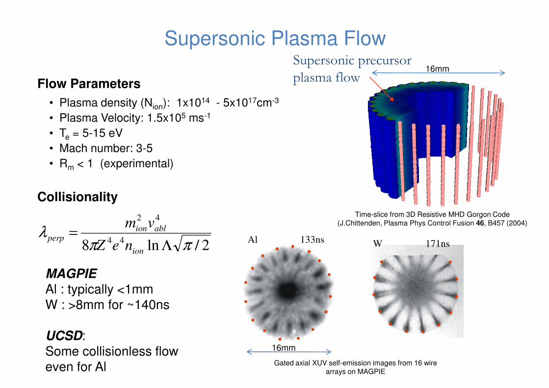
Supersonic Plasma Flow
• Plasma density (Nion): 1x10¹⁴ - 5x1017cm-3
• Plasma Velocity: 1.5x10⁵ ms-1
• T = 5-15 eV
Supersonic precursor
plasma flowFlow Parameters
16mm
• Te = 5-15 eV
• Mach number: 3-5
• Rm < 1 (experimental)
2/ln8 44
42
ππλ
Λ=
ion
ablionperp
neZ
vm
Collisionality
133ns 171nsWAl
Time-slice from 3D Resistive MHD Gorgon Code (J.Chittenden, Plasma Phys Control Fusion 46, B457 (2004)
MAGPIE
Al : typically <1mm
W : >8mm for ~140ns
UCSD:
Some collisionless flow
even for Al
16mm
Gated axial XUV self-emission images from 16 wire arrays on MAGPIE
Shock formation in supersonic plasma flow
Collisional systems:
• e.g. Nested Wire Arrays at >1MA
Outer array wires
Plasma flowfrom outer array
Inner array wires
Axis
Shock formation in supersonic plasma flow
Collisional systems:
• e.g. Nested Wire Arrays at >1MA
• Data from 32 outer and 16 inner Al wires on MAGPIE
Outer arrayposition
Outer array wires
Plasma flowfrom outer array
Axial gated XUV self-emission imaging of nested Al arrays on MAGPIE (D.J.Ampleford in prep. PRL)
on MAGPIE
• Bow shocks formed around inner wires
• Secondary shocking also observed
• D.J.Ampleford at HEDLA
Shock formation in supersonic plasma flow
Collisional systems:
• e.g. Nested Wire Arrays at >1MA
• Data from 32 outer and 16 inner Al wires on MAGPIE
Outer arrayposition
Outer array wires
Plasma flowfrom outer array
Collisionless systems:
Axial gated XUV self-emission imaging of nested Al arrays on MAGPIE (D.J.Ampleford in prep. PRL)
XUV Spectroscopy
on MAGPIE
• Bow shocks formed around inner wires
• Secondary shocking also observed
• D.J.Ampleford at HEDLA
Generator
Axis
• UCSD experiments will provide collisionless flow,
• E.g. Laser driven experiments by Bell et
al Phys Rev A, 38, p1363 (1998)
• Good diagnostic access and shot rate
Ireturn Iwire
J x Bwire return
Ablated plasma flowaccelerated by JxB force
CATHODE ANODE
P = vflow ρ2
Single metal wireX
Radiography andimaging diagnostics
Obstruction
Precursor Column parameters
• Nion : 1018-1022 cm-3 (0.1 – 1 kg/m3)
• Z: (Al) ~7, (W) ~ 14
• Te ~ 60eV – 100 eV
• Diameter: 0.5-3 mm
Dense precursor
condensation on
axis
Inertially Confined plasma column formed
• Diameter: 0.5-3 mm
ArrayAxis
-1 0 1 2 3 4 5 6 7 8 9 10 11 12 13 14 15 16 17 18
0.0
0.5
1.0
1.5
2.0
2.5
3.0
Film
contr
ast
/ arb
. units
Scale / mm
133ns
163ns
193ns
3.0
3.5
4.0
4.5
5.0Radiography Data
COBRA
MAGPIE
Rocket Model
precursor radius = 0.6mm
Vabl
= 1.5 x 10⁵ ms
-1
COBRA
MAGPIE
Den
sity /
kg
m-3
Axis
Axial (lineouts right) and radial gated XUV self-emission images, along with column density with time for MAGPIE and COBRA W experiments (Bott et al, Phys Rev E, 74 046403 (2006))
Radiatively cooled and steady state (several shock transit times)
0 25 50 75 100 125 150 175 200 225 250 275 300
0.0
0.5
1.0
1.5
2.0
2.5 MAGPIE
Den
sity /
kg
m
Time / ns16mm
Optical Streak Photograph from MAGPIE of 32 wire Al array
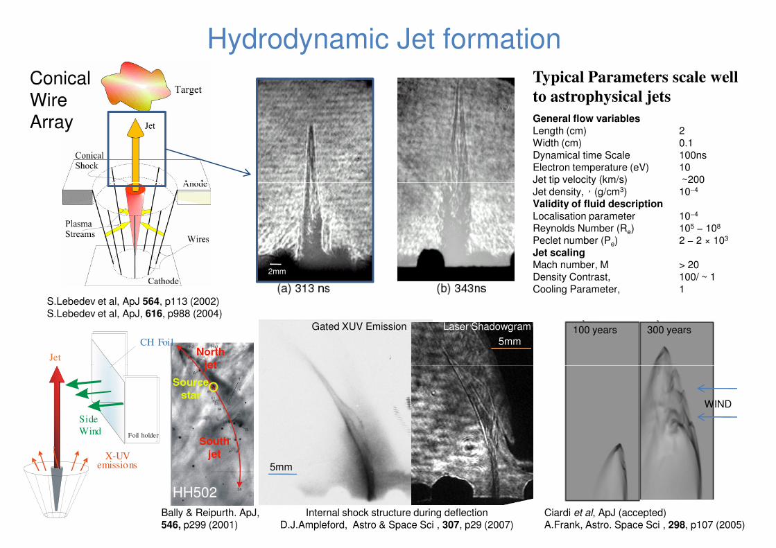
Typical Parameters scale well
to astrophysical jets
Hydrodynamic Jet formation
General flow variablesLength (cm) 2
Width (cm) 0.1Dynamical time Scale 100nsElectron temperature (eV) 10Jet tip velocity (km/s) ~200
Conical
Wire
Array
Jet tip velocity (km/s) ~200�Jet density, (g/cm3) 10−4
Validity of fluid description
Localisation parameter 10−4
Reynolds Number (Re) 105 − 108
Peclet number (Pe) 2 − 2 × 10³
Jet scalingMach number, M > 20Density Contrast, 100/ ~ 1
Cooling Parameter, 1S.Lebedev et al, ApJ 564, p113 (2002)S.Lebedev et al, ApJ, 616, p988 (2004)
2mm
Gated XUV Emission Laser Shadowgram 100 years 300 years5mm
Jet
CH Foil
Internal shock structure during deflectionD.J.Ampleford, Astro & Space Sci , 307, p29 (2007)
Ciardi et al, ApJ (accepted)A.Frank, Astro. Space Sci , 298, p107 (2005)
WIND
5mmX-UV
emissions
Foil holder
Side
Wind
Bally & Reipurth. ApJ, 546, p299 (2001)
HH502
Variation of jet parameters: Jets at UCSD• Range of jet parameters possible using different currents (e.g. 2 Generators at UCSD &
MAGPIE)
• First free propagating jets from x-pinches recently measured at UCSD at 80 kA
ρ (cm-2) 4.5
Are
al E
lectr
on
Density (
x 1
0 c
m)
17
-2
166 ns
D.M.Haas at APS 2007, and in prep. APL
5.5 x 10¹⁷
1 x 10¹⁶
8 x 10¹⁷
ρe (cm-2)
3
-1 0 1 2 3 4 5 6 7 8 91
1.5
2
2.5
3.5
4.5
4
Distance From top of Anode (mm)
AverageBackground
Level
Are
al E
lectr
on
Density (
x 1
0 c
m)
17
-2
2mm
Parameter 80 kA X-pinch measured 250 kA Conical Expected (HEDLA)Vjet 3.3 x 10⁴ ms-1 1 x 10⁵ ms-1 (100 km/s)cs (radial exp) 5.5 x 10³ ms-1
M 4-8 M > 10ρe (cm-3 ) few x 1017 ~ 1018 - 1019
T (eV) ~15 ~15 Z ~5 ~ 5
D.M.Haas at APS 2007, and in prep. APL
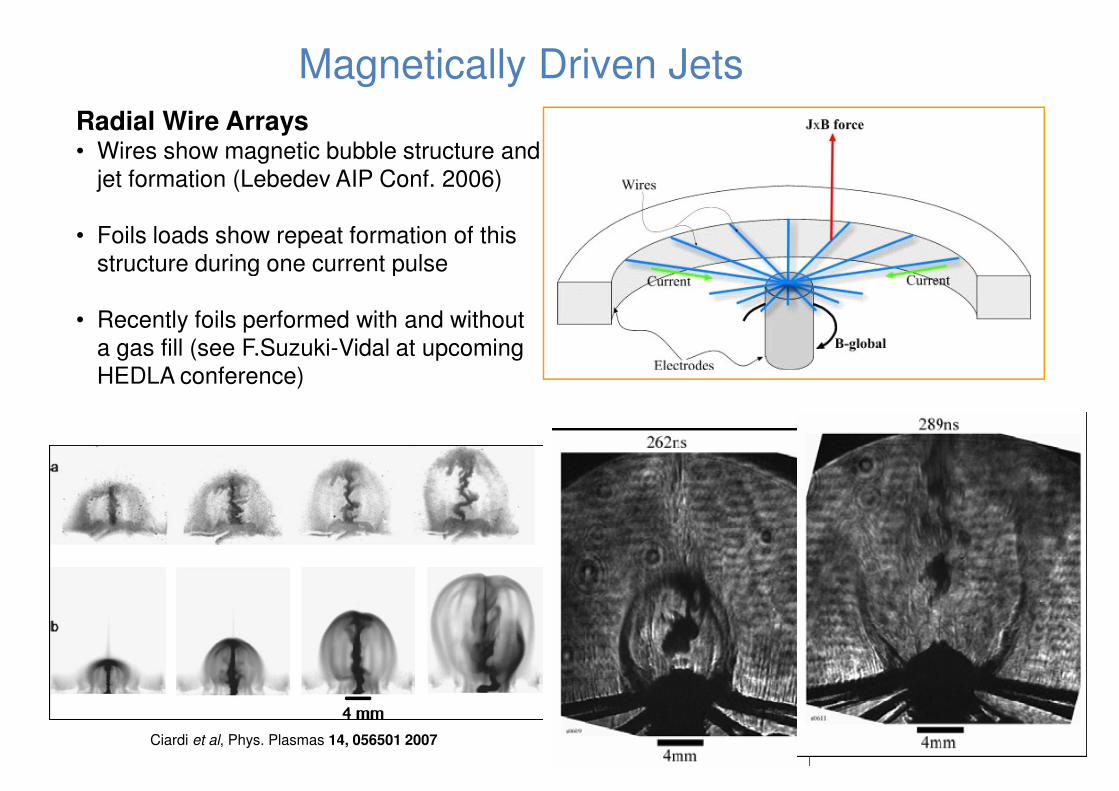
Magnetically Driven Jets
Radial Wire Arrays• Wires show magnetic bubble structure and
jet formation (Lebedev AIP Conf. 2006)
• Foils loads show repeat formation of this structure during one current pulsestructure during one current pulse
• Recently foils performed with and without a gas fill (see F.Suzuki-Vidal at upcoming HEDLA conference)
Ciardi et al, Phys. Plasmas 14, 056501 2007
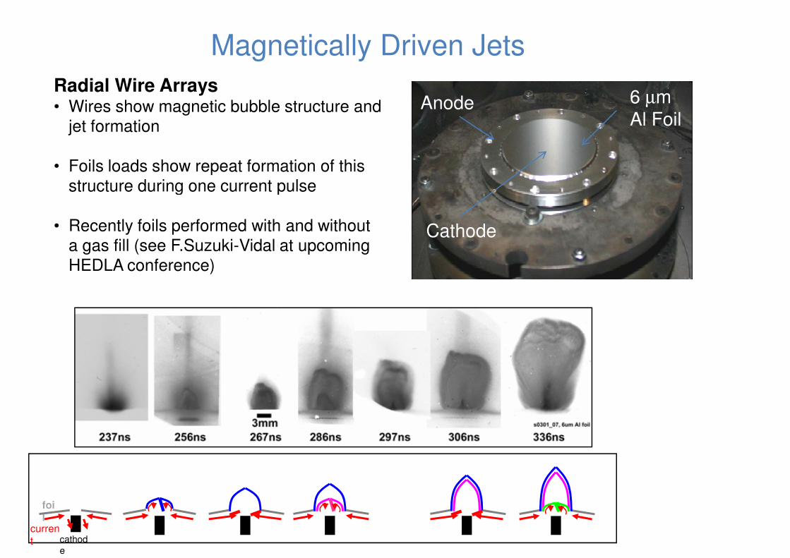
Magnetically Driven Jets
6 µm
Al FoilAnode
Radial Wire Arrays• Wires show magnetic bubble structure and
jet formation
• Foils loads show repeat formation of this structure during one current pulse
Cathode
structure during one current pulse
• Recently foils performed with and without a gas fill (see F.Suzuki-Vidal at upcoming HEDLA conference)
current cathod
e
foil
Magnetically Driven Jets
Radial Wire Arrays• Wires show magnetic bubble structure and
jet formation
• Foils loads show repeat formation of this structure during one current pulsestructure during one current pulse
• Recently foils performed with and without a gas fill (see F.Suzuki-Vidal at upcoming HEDLA conference)
current cathod
e
foil
Future Studies at UCSD
UCSD Drivers
• Good diagnostic access, high shot rate• 2 generators to give plasma source, and independent
B-field or second plasma
Jet
GenASIS
250 kALTD
10
mm
Single metal wire
20 - 40 mm
Parameter space accessible
Can adjust Plasma ρ : nion ~1014 – 1017 cm-3
B-field: Variable up to ~50T (200 kA)
Difficult to adjust: Plasma velocity (ablation physics)T: 10eV in flow, 60-100 eV in column
Material At No. below 6(C) (typ. 13, Al)
Physical Conditions: Collisionality of flowMagnetization of ions
β
Jet propagation into B-field
Ireturn Iwire
X-Pinch
80 kA
10 m
m
AnodeCathode X-Pinch80 kA
Marx
10
mm
10 mm
Low T limits plasma to low βNeed to investigate application to cosmic shocks (Drake PoP 2000)
Modelling
• GORGON for hydro and magnetic jets (J. Chittenden & A.Ciardi)
• Also use of LSP, h2d, and ePlas at UCSD
Kinetic compression of exploding foil
P = vflow ρ2
Single metal wire
GenASIS250 kA
LTD
80 kAMarx
MetalFoil
Cathode Anode
20 - 40 mm
10 m
m
Imperial College / UCSD Collaborative Studies
Imperial College: High current drive, extensive diagnostics, experienced team
UCSD: 2 drivers, high shot rate in simplified set-ups
Precursor Compression of targets using ablated
Iarray
Ablated plasmaflow
Precursor Column
WIRES
P = vflow ρ2
JxB force ANODE
Compression of targets using ablated plasma flow
Pressures: 1 – 100 kbar
AXIS
Bglobal CATHODE
Imperial College / UCSD Collaborative Studies
Imperial College: High current drive, extensive diagnostics, experienced team
UCSD: 2 drivers, high shot rate in simplified set-ups
Bz Compression of targets using ablated
Iarray
Ablated plasmaflow
WIRES
P = vflow ρ 2
JxB force ANODE
Bz
Iφ
Compression of targets using ablated plasma flow
Pressures: 1 – 100 kbar
Magnetic field in precursor column
Twisted Arrays
Bglobal CATHODE
Imperial College / UCSD Collaborative Studies
Imperial College: High current drive, extensive diagnostics, experienced team
UCSD: 2 drivers, high shot rate in simplified set-ups
Compression of targets using ablated
Iarray
A blated plasmaflow
WIRES
P = vflow ρ 2
JxB force ANODE
Current DriveMarx or
inductive split
Compression of targets using ablated plasma flow
Pressures: 1 – 100 kbar
Magnetic field in precursor column
Twisted ArraysInductive split from main current
Bglobal CATHODE
current
Additional generator
Imperial College / UCSD Collaborative Studies
Imperial College: High current drive, extensive diagnostics, experienced team
UCSD: 2 drivers, high shot rate in simplified set-ups
B Compression of targets using ablated
Iarray
Ablated plasma
flow
Thin-WalledMetal tube
WIRES
P = vflow ρ 2
JxB force ANODE
Bz Compression of targets using ablated plasma flow
Pressures: 1 – 100 kbar
Magnetic field in precursor column
Twisted ArraysInductive split from main current
Bglobal CATHODE
current
Additional generator
B-field flux compression
Imperial College / UCSD Collaborative Studies
Imperial College: High current drive, extensive diagnostics, experienced team
UCSD: 2 drivers, high shot rate in simplified set-ups
Precursor Column
Iarray
Bglobal
Ablated plasmaflow
P = vflow
ρ2
JxB force
Jet
Jet Interaction Experiments
Use of radial / conical arrays for interaction with
Precursor plasma column
Magnetised precursorJet
Counter-propagating jet
Jets and outflows from pulsed power driven plasmas
Well characterised……
• Generation and deflection of hydrodynamic jets
• Generation of magnetically driven jets• Generation of magnetically driven jets
Systems developing…..
•Multi-stage magnetically driven jets
•Low jet/ambient medium density ratio experiments
•Hydro Jet work at UCSD
•Jets with angular momentum (Ampleford, PRL 100, p035001, 2008)
To come……
•Compression of magnetised plasmas
•Propagation of plasma into B-field / magnetised targets