29 Application of Seismic Refraction Tomography to Karst Cavities Jacob R. Sheehan 1 , William E. Doll 1 , David B. Watson 2 , Wayne A. Mandell 3 1 Battelle, 105 Mitchell Rd, Suite 103, Oak Ridge, TN 37830 2 Oak Ridge National Laboratory, 1 Bethel Valley Rd, Oak Ridge, TN 37831 3 U.S. Army Environmental Center, 5179 Hoadley Rd, Aberdeen, MD 21010 ABSTRACT For three years we have used synthetic and field data to investigate the effectiveness of commercial refraction tomography codes on both simple and complex subsurface velocity structures, with the ultimate goal of determining the suitability of the method for karst problems. The results of these studies indicate that refraction tomography is able to resolve karst features under some conditions. The analysis of field data acquired on the Oak Ridge Reservation, TN shows low velocity zones on three parallel seismic lines. These zones are located at similar depths and fall on a line that is parallel to geologic strike, leading to an interpre- tation of a possible karst conduit. This feature has velocities of about 1500-2000 m/s in a matrix of 3000- 4000 m/s, reasonable velocities for a mud filled void in saprolite at these depths. Drilling of this feature is anticipated in the near future. Analysis of a seismic line taken over the known mud-filled cavity shows a low velocity feature with a location consistent with drilling results. The velocity of the feature is about 1000 m/s, a value that is a little lower than that found for the features discussed above. Synthetic modeling some- times generates results similar to the field results, but often fails to image cavities as well, or at all. Ongoing investigations are aimed at refining our understanding of the circumstances where these methods can be suc- cessful, and investigating the relevance of model results to actual field conditions. INTRODUCTION Oak Ridge National Laboratory and Battelle have been working with the United States Army Environmental Center to assess the performance of seismic refraction tomography (SRT) for karst ter- rains (Sheehan et al, 2005a, Sheehan et al, 2004, Sheehan et al, 2003). These terrains frequently con- tain sinkholes, irregular and gradational bedrock interfaces, remnants of high velocity bedrock above these interfaces, deeply weathered fractures, and voids that may be air-, water-, or mud-filled. The seismic velocity of unconsolidated sedi- ments and voids associated with karst features usu- ally differs significantly from carbonate parent rock, making seismic methods a possible tool for mapping such features. In this paper, we are concerned with detection of karst voids, and will not be concerned with depressions, pinnacles, grikes, or other karst morphologic features (Carpenter et al, 1998). Many seismic methods have been applied to karst problems, but few have been successful. Some success has been attained in detecting sink- holes, or other structural features that lie above voids, but it has proven difficult to image or detect cavities with seismic methods. Conventional seis- mic refraction methods (e.g. delay-time or general- ized reciprocal) in particular fall short because air- water- or mud-filled voids occur as velocity lows, and these are largely incompatible with the constant velocity layered models that these methods require (Doll et. al, 1999). Our first step in evaluating the effectiveness of SRT for karst detection was to use synthetic travel- times generated from 2-D models using the refrac- tion tomography code GeoCT-II (version 2.3) (GeoTomo, LLC). The synthetic models allow us to have a “reference” model with which to compare the results generated by SRT using another refraction tomography code, Rayfract™ (version 2.51, Intelli- gent Resources Inc.). No synthetic model will ever be a completely accurate depiction of the real subsurface. Models are comprised of discrete units, which are further
Transcript
29
Application of Seismic Refraction Tomography to Karst Cavities
Jacob R. Sheehan1, William E. Doll1, David B. Watson2, Wayne A. Mandell31Battelle, 105 Mitchell Rd, Suite 103, Oak Ridge, TN 378302Oak Ridge National Laboratory, 1 Bethel Valley Rd, Oak Ridge, TN 378313 U.S. Army Environmental Center, 5179 Hoadley Rd, Aberdeen, MD 21010
ABSTRACT
For three years we have used synthetic and field data to investigate the effectiveness of commercial refraction tomography codes on both simple and complex subsurface velocity structures, with the ultimate goal of determining the suitability of the method for karst problems. The results of these studies indicate that refraction tomography is able to resolve karst features under some conditions. The analysis of field data acquired on the Oak Ridge Reservation, TN shows low velocity zones on three parallel seismic lines. These zones are located at similar depths and fall on a line that is parallel to geologic strike, leading to an interpre-tation of a possible karst conduit. This feature has velocities of about 1500-2000 m/s in a matrix of 3000-4000 m/s, reasonable velocities for a mud filled void in saprolite at these depths. Drilling of this feature is anticipated in the near future. Analysis of a seismic line taken over the known mud-filled cavity shows a low velocity feature with a location consistent with drilling results. The velocity of the feature is about 1000 m/s, a value that is a little lower than that found for the features discussed above. Synthetic modeling some-times generates results similar to the field results, but often fails to image cavities as well, or at all. Ongoing investigations are aimed at refining our understanding of the circumstances where these methods can be suc-cessful, and investigating the relevance of model results to actual field conditions.
INTRODUCTION
Oak Ridge National Laboratory and Battelle have been working with the United States Army Environmental Center to assess the performance of seismic refraction tomography (SRT) for karst ter-rains (Sheehan et al, 2005a, Sheehan et al, 2004, Sheehan et al, 2003). These terrains frequently con-tain sinkholes, irregular and gradational bedrock interfaces, remnants of high velocity bedrock above these interfaces, deeply weathered fractures, and voids that may be air-, water-, or mud-filled.
The seismic velocity of unconsolidated sedi-ments and voids associated with karst features usu-ally differs significantly from carbonate parent rock, making seismic methods a possible tool for mapping such features. In this paper, we are concerned with detection of karst voids, and will not be concerned with depressions, pinnacles, grikes, or other karst morphologic features (Carpenter et al, 1998).
Many seismic methods have been applied to karst problems, but few have been successful.
Some success has been attained in detecting sink-holes, or other structural features that lie above voids, but it has proven difficult to image or detect cavities with seismic methods. Conventional seis-mic refraction methods (e.g. delay-time or general-ized reciprocal) in particular fall short because air- water- or mud-filled voids occur as velocity lows, and these are largely incompatible with the constant velocity layered models that these methods require (Doll et. al, 1999).
Our first step in evaluating the effectiveness of SRT for karst detection was to use synthetic travel-times generated from 2-D models using the refrac-tion tomography code GeoCT-II (version 2.3) (GeoTomo, LLC). The synthetic models allow us to have a “reference” model with which to compare the results generated by SRT using another refraction tomography code, Rayfract™ (version 2.51, Intelli-gent Resources Inc.).
No synthetic model will ever be a completely accurate depiction of the real subsurface. Models are comprised of discrete units, which are further
30
broken down into small constant velocity grid cells. This means that however carefully constructed and applied, numerical analysis is based upon simplified and digitized representations of physical laws and models. In addition, most commercially available numerical modeling packages are based on two dimensional models. Three dimensional numerical analysis is in development, but is currently too com-putationally-intensive to be practical for most appli-cations.
Field testing complements the models by pro-viding realistic parameters and a basis for determin-ing model validity. For this we used five refraction tomography profiles collected in support of the Nat-ural and Accelerated Bioremediation Research (NABIR) Field Research Center (FRC). NABIR is a DOE sponsored research program to develop and evaluate bioremediation tools for contaminated sites. Liquid wastes containing nitrate, uranium, technetium, tetrachloroethylene, and other contami-nants were disposed of in sludge ponds until the mid-1980s, at which time the ponds were remedi-ated and capped with a parking lot. A large contam-ination plume within the underlying unconsolidated saprolite and inter-bedded shale and carbonate bed-rock is now spreading away from the site of the old ponds.
CONVENTIONAL AND TOMOGRAPHIC REFRACTION TOMOGRAPHY
Conventional refraction inversion methods use a “layer cake” approach. The subsurface is divided into a number of continuous constant velocity layers with velocities and thicknesses that are varied through interactive forward modeling in an effort to match the traveltimes that are determined from the field data. These methods require that sections of the traveltime curves be mapped to refractors, a task that can be difficult at best in karst situations. The pres-ence of karst features means that there can be large and sudden changes in the shape of the bedrock. There can also be localized features such as voids that contradict the assumption of continuous con-stant velocity layers.
Unlike conventional refraction methods, SRT does not require that the model be broken into
constant velocity continuous layers. Instead the model is made up of a high number of small constant velocity grid cells or nodes. Inversion is performed by an automated procedure which involves raytrac-ing through an initial model and comparing the mod-eled traveltimes to the field data, and adjusting the model grid-by grid in order to match the modeled traveltimes to the field data. This process is itera-tively repeated until a preset number of iterations as been reached. Because there is no assumption of continuous constant velocity layers, SRT can model localized velocity anomalies.
RESULTS
Synthetic
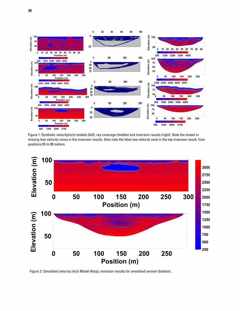
Synthetic models were used to test various properties, limitations and capabilities of SRT for cavity detection. A sample of the models that have been studied and the inversion results are shown in Figure 1. The most basic requirement for detecting a cavity is to have adequate ray coverage in the area surrounding it. Both survey geometry and the veloc-ity structure affect the ray coverage. As the effect of geometry is well-understood, we will focus on the effect of the velocity structure.
In order to be able to image a cavity success-fully, there must be rays that penetrate deeper than the cavity and can be refracted back to the surface. One factor that can limit the depth of penetration is the presence of sharp high-contrast velocity bound-aries. These boundaries cause most of the seismic energy to be reflected back to the surface. The energy that passes through the transition is refracted to shallow angles, limiting the depth of penetration within the area below the transition.
Even if energy does penetrate to adequate depths to image a cavity, it must have a path back to the surface in order to be detected. Seismic rays can return to the surface if there is a change in velocity under the cavity. This can be in the form of a verti-cal velocity gradient. Normally, velocities will increase slightly with depth in sedimentary rocks, so in a karst investigation this requisite can be easily met.
31
Ray coverage alone is not enough to insure that the cavity can be detected. Models that are otherwise identical can be created with and without voids to evaluate travel time changes due to the void. We have found cases where the ray coverage around the cavity is extensive, but the first arrival traveltimes generated from the model do not reflect the presence of the cavity, making it impossible for the inversion algorithm to detect the cavity. Even when a cavity has a significant effect on the travel times, the inver-sion may result in a feature with velocities only slightly lower than that of the surrounding volume. This muted response is unlikely to give the user con-fidence that a cavity has actually been detected.
In some cases applying matrix smoothing to the synthetic model before performing raytracing increases the effect of the cavity on the traveltimes, and allows the inverted result to better match the true model. An example of this is shown in Figure 2. In other cases smoothing has no effect at all.
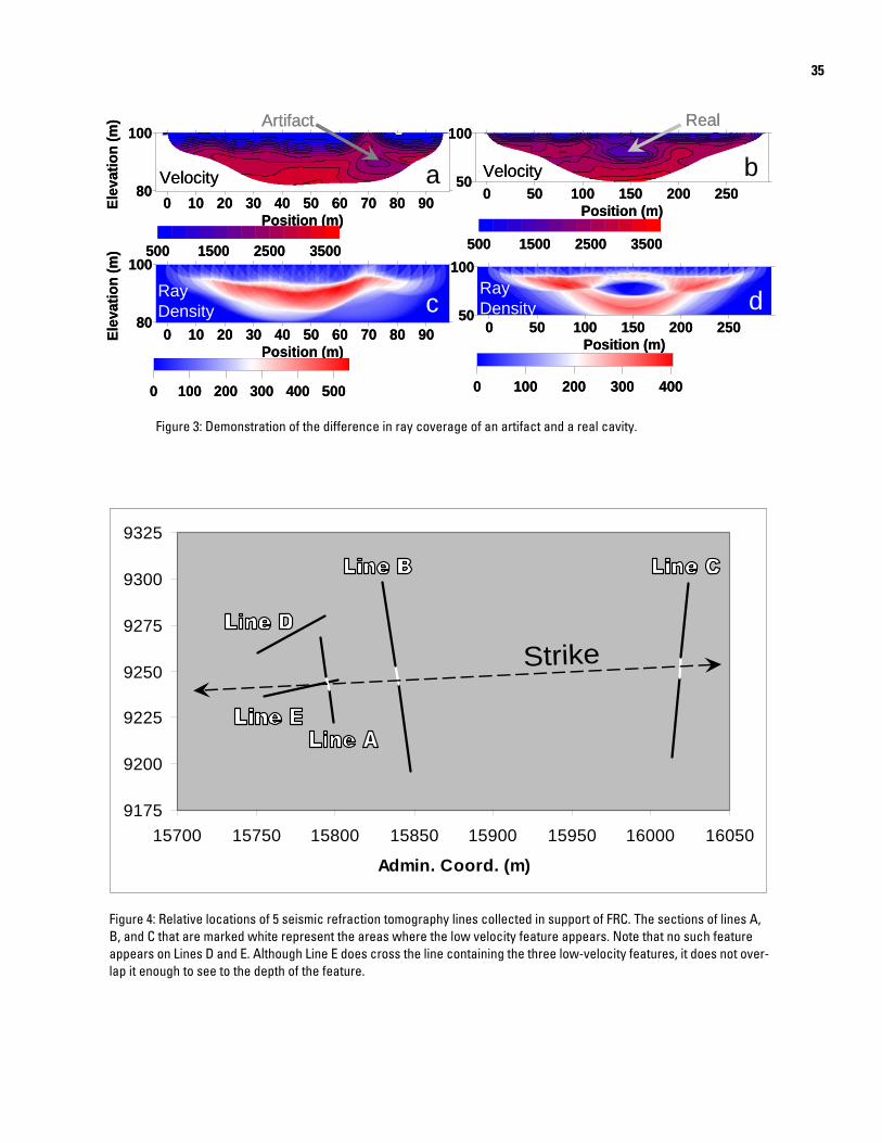
SRT can create false positives as well as false negatives such as in the top result shown in Figure 1. These artifacts have been observed when inverting synthetic data, which does not include the inevitable noise and picking errors and inaccuracies. The inclu-sion of such factors is likely to increase the occur-rence of both false negatives and positives. One way artifacts can sometimes be distinguished from real features is by examining the ray coverage. In the case of a real low-velocity feature, the ray coverage should be nearly zero within the feature. Artifacts are usually caused by an area of low ray coverage, but not as low as is usually the case with a true fea-ture. A good example of this is shown in Figure 3. Figure 3a shows an artifact where indicated. Figure 3b shows the ray coverage for this model. The ray coverage in the vicinity of the cavity is low com-pared to the high coverage area above it that is caused by the increase in velocity. Figure 3c shows a feature that is real. Note that the ray coverage (Fig-ure 3d) is drastically lower in the area of the cavity.
Field Results
Four new refraction tomography profiles (des-ignated by Line A, C, D and E, Figure 4) were acquired in support of research at the NABIR FRC
site (Sheehan et. al, 2005b). Lines A and C are ori-ented parallel to an earlier line (Doll et al., 2002), designated Line B for this paper.
Lines A, D, and E used one-meter receiver spacing and two-meter shot spacing. Line B con-sisted of three collinear lines and combined for anal-ysis. Line C was collected using 2 meter receiver spacing and 4 meter shot spacing. All data were col-lected using a 48 channel Geometrics Strataview seismograph. Ten Hz geophones were used for Lines A, C, D and E and 40 Hz receivers were used for line B.
Lines A, B and C each show a very well-defined (~ 10m wide) low velocity feature (Figure 5). These low velocity features are all similar in size, at the same approximate depth, and fall on a line that is parallel to geologic strike at the field site (Figure 4). There is no such feature in lines D or E, which run roughly parallel to strike and perpendicular to the other three lines.
The ray coverage for Lines A and C are shown in Figure 6. In both cases the area of the low veloc-ity feature has very low ray coverage, just as in the example discussed above and shown in Figure 3. Because of this and the correlation to geologic strike it is reasonable to assume that these low velocity fea-tures are not artifacts, but rather indicate a long con-duit in the carbonate bedrock. This feature yields seismic velocities of approximately 1500-2000 m/s in a matrix of 3000-4000 m/s. The apparent cavity is below the water table so it cannot be air-filled, but its velocity is so low that we must surmise that it is water- or mud-filled.
Mud-filled Cavity
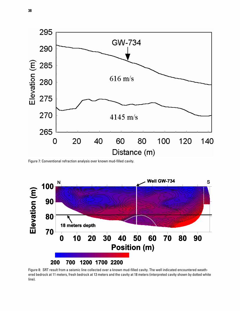
We examined a refraction tomography line taken over a known mud-filled cavity centered on a well designated GW-734 investigated by Doll et al., 1999 and described in Doll et al., this volume. In the previous work at this site various geophysical meth-ods were utilized in an effort to characterize a known mud-filled cavity. One of the methods used was con-ventional delay-time refraction analysis. The seis-mic analysis provided a bedrock profile that
32
matched the drilling logs, but was unable to image the cavity.
During installation of well GW-734, drillers encountered the cavity starting at a depth of 18 meters, and extending to at least 30 meters. Conven-tional refraction analysis at this site failed to show the cavity (Figure 7). The SRT result for the line shows a low velocity feature with a location consis-tent with the drilling results (Figure 8). The velocity of the feature is about 1000 m/s. The velocity of the surrounding area is about 2750 m/s, which is consis-tent with measured velocities for fractured and weathered carbonate at this locale.
CONCLUSIONSOur assessment of synthetic models for deter-
mining the capabilities and limitations of seismic refraction for cavity detection has had mixed results. Usually the cavity will be represented in the inver-sion result, but the velocity will not be as low as it should be. At other times the cavity is not detected at all. In one case applying matrix smoothing to the model before generating the synthetic data allowed the cavity to be detected when it was previously undetectable. However, smoothing other models did not have such a positive effect, demonstrating the complexity of synthetic modeling and analysis.
Analysis of field data suggests that SRT is capa-ble of imaging cavities. Four seismic lines from two separate sites on the Oak Ridge Reservation show possible and known cavities. At the FRC a low velocity feature occurs at a consistent depth and fall-ing along a line parallel to geologic strike. Another seismic line was collected over a cavity that had been found by drilling. The drilling found that the top of the cavity is at a depth of about 18 meters and the bottom was at 30 meters or deeper. The SRT result shows a low velocity feature at a depth that is consistent with the drilling results.
SRT has the potential to be an effective tool for studies where the presence of cavities needs to be detected. It is not a fail-proof method, however. False positives and negatives are possible.
Future Work
We hope to build a physical scaled model in order to further evaluate the effectiveness of refrac-tion tomography and to improve synthetic modeling procedures. This will allow controlled acquisition of data from a known three-dimensional model while avoiding many of the limitations of computer models. To the extent that a model is an accurate representation of the problem of interest, data collected using a physical model will more reliably replicate the physical response without errors asso-ciated with discretizing the properties of a model. In addition, a physical model, as long as it is large enough, will include 3-D effects.
Comparison of the traveltimes generated from digital and physical versions of the same model should greatly improve our understanding of the behavior of digital computer models. This would in turn allow more effective use of computer models for all types of geologic settings.
REFERENCES
Carpenter, P. J., W. E. Doll, and R. D. Kaufmann, 1998 Geophysical character of buried sinkholes on the Oak Ridge Reservation, Tennessee, Jour. Environmental and Engineering Geophysics, v. 3, p. 133-146.
Doll, W.E., J. E. Nyquist, P. J. Carpenter, R. D. Kauf-mann and B. J. Carr, 1998 Geophysical Surveys of a Known Karst Feature, Oak Ridge Y-12 Plant, Oak Ridge, Tennessee, Jour. Environmental and Engineer-ing Geophysics, v. 3, p. 133-146, 1998
Doll, W.E., J.E. Nyquist, P.J. Carpenter, R.D. Kaufmann, and B.J. Carr, 1999, Geophysical surveys of a known karst feature: Oak Ridge Y-12 Plant, Oak Ridge, Ten-nessee, in Geo-engineering for underground facilities, ASCE Geotechnical Special Publication No. 90, G. Fernandez and R. Bauer, ed., p. 684-694.
Doll, W.E., T.J. Gamey, D.B. Watson, and P.M. Jardine, 2002. Geophysical profiling in support of a nitrate and uranium groundwater remediation study, 2002 Annual Meeting of the Symposium on the Application of Geo-physics to Engineering and Environmental Problems, Las Vegas, NV, February 10-14 2002.
33
Doll, W.E., B.J. Carr, J.R. Sheehan, and W.A. Mandell, this volume, Application of Seismic Refraction Tomography to Karst Cavities
Sheehan, J.R., W. E. Doll, and W. Mandell, 2003. Evalu-ation of refraction tomography codes for near-surface applications. Extended abstract, presented at the 2003 Annual Meeting of the Society of Exploration Geo-physicists, Dallas TX, October 26-31, 2003, 4.
Sheehan, J.R., W. E. Doll and W. Mandell, 2004. Com-parison of MASW and Refraction Tomography. Extended abstract, presented at the 2004 Annual Meeting of the Symposium on the Application of Geo-physics to Engineering and Environmental Problems, Colorado Springs, CO, February 22-26 2004.
Sheehan, J.R., W. E. Doll and W.A. Mandell, 2005a. An Evaluation of Methods and Available Software for Seismic Refraction Tomography Analysis, Jour. Envi-ronmental and Engineering Geophysics, v. 10, p. 21-34, 2005
Sheehan, J.R., W. E. Doll and W.A. Mandell, and D.B. Watson, 2005b. Detecting Cavities with Seismic Refraction Tomography: Can it be done?. Extended abstract, presented at the 2005 Annual Meeting of the Symposium on the Application of Geophysics to Engi-neering and Environmental Problems, Atlanta, GA, April 3-7, 2005.
34
Figure 2: Smoothed velocity (m/s) Model 4(top), inversion results for smoothed version (bottom).
0 10 20 30 40 50 60 70 80 9080
100
Elev
atio
n (m
)
0 50 100 150 200 250
255075
100
Elev
atio
n (m
)
0 50 100 150 200 25050
75100
Elev
atio
n (m
)
0 50 100 150 200 250
5075
100
Elev
atio
n (m
)
250 1250 2250 3250 4500
1250 2250 3250 4250 5250
500 1500 2500 3500 4500
500 1250 2000 2750
0 10 20 30 40 50 60 70 80 90Position (m)
80
90
100
Elev
atio
n (m
)
0 50 100 150 200 250 300Position (m)
50
100
Elev
atio
n (m
)
0 50 100 150 200 250 300Position (m)
50
100
Elev
atio
n (m
)
0 50 100 150 200 250 300Position (m)
50
100
Elev
atio
n (m
)
250 1250 2250 3250 4250
1250 2250 3250 4250 5250
500 1500 2500 3500 4500
500 1250 2000 2750
0255075
0 100 200 300
0
25
50
0 100 200 300
0
25
0 20 40 60 80 100
0255075
0 100 200 300
0255075
0 100 200 300
0
25
50
0 100 200 300
0
25
0 20 40 60 80 100
0255075
0 100 200 300
Figure 1: Synthetic velocity(m/s) models (left), ray coverage (middle) and inversion results (right). Note the muted or missing low-velocity zones in the inversion results. Also note the false low velocity zone in the top inversion result, from positions 65 to 80 meters.
0 50 100 150 200 250Position (m)
50
100
Elev
atio
n (m
)
0 50 100 150 200 250 300Position (m)
50
100
Elev
atio
n (m
)
250
500
750
1000
1250
1500
1750
2000
2250
2500
2750
3000
35
0 50 100 150 200 250
Position (m)
50
100
0 50 100 150 200 250
Position (m)
50
100
0 100 200 300 400
0 10 20 30 40 50 60 70 80 90
Position (m)
80
100
Ele
va
tio
n (
m)
0 10 20 30 40 50 60 70 80 90
Position (m)
80
100
Ele
va
tio
n (
m)
0 100 200 300 400 500
500 1500 2500 3500500 1500 2500 3500
Artifact Real
VelocityVelocity
Ray
Density
Ray
Density
0 50 100 150 200 250
Position (m)
50
100
0 50 100 150 200 250
Position (m)
50
100
0 100 200 300 400
0 10 20 30 40 50 60 70 80 90
Position (m)
80
100
Ele
va
tio
n (
m)
0 10 20 30 40 50 60 70 80 90
Position (m)
80
100
Ele
va
tio
n (
m)
0 100 200 300 400 500
500 1500 2500 3500500 1500 2500 3500
Artifact Real
VelocityVelocity
Ray
Density
Ray
Densityc
ba
d
Fi 3 D t ti f th diff i f tif t d l it
9175
9200
9225
9250
9275
9300
9325
15700 15750 15800 15850 15900 15950 16000 16050
Admin. Coord. (m)
Strike
9175
9200
9225
9250
9275
9300
9325
15700 15750 15800 15850 15900 15950 16000 16050
Admin. Coord. (m)
Strike
Figure 3: Demonstration of the difference in ray coverage of an artifact and a real cavity.
Figure 4: Relative locations of 5 seismic refraction tomography lines collected in support of FRC. The sections of lines A, B, and C that are marked white represent the areas where the low velocity feature appears. Note that no such feature appears on Lines D and E. Although Line E does cross the line containing the three low-velocity features, it does not over-lap it enough to see to the depth of the feature.
36
0 5 10 15 20 25 30 35 40 45Position (m)
75
80
85
90
95
100
Elev
atio
n (m
)
0 10 20 30 40 50 60 70 80 90Position (m)
60
70
80
90
100
Elev
atio
n (m
)
500 1500 2500 3500 4500
30 40 50 60 70 80 90 100 110 120 130Position (m)
70
80
90
100
Elev
atio
n (m
)
Figure 5: Velocity results (m/s) from three parallel seismic lines all showing a similar low-velocity zone. The top line is A, the middle line is B, and the bottom line is C.
37
0 5 10 15 20 25 30 35 40 45Position (m)
75
80
85
90
95
100El
evat
ion
(m)
0 10 20 30 40 50 60 70 80 90Position (m)
270
280
290
300
Elev
atio
n (m
)
0
50
100
150
200
250
300
350
Figure 6: Ray coverage for FRC lines A (top) and C (bottom). Note the low coverage areas that correspond to the low velocity zones. This is in contrast to the case for the artifact shown in figure 3.
38
Figure 7: Conventional refraction analysis over known mud-filled cavity.
0 10 20 30 40 50 60 70 80 90Position (m)
70
80
90
100
Elev
atio
n (m
)
200 700 1200 1700 2200
18 meters depth
Well GW-734N S
0 10 20 30 40 50 60 70 80 90Position (m)
70
80
90
100
Elev
atio
n (m
)
200 700 1200 1700 2200
18 meters depth
Well GW-734N S
0 10 20 30 40 50 60 70 80 90Position (m)
70
80
90
100
Elev
atio
n (m
)
200 700 1200 1700 2200
18 meters depth
Well GW-734N S
Figure 8: SRT result from a seismic line collected over a known mud-filled cavity. The well indicated encountered weath-ered bedrock at 11 meters, fresh bedrock at 13 meters and the cavity at 18 meters (interpreted cavity shown by dotted white line).
39
Borehole geophysical techniques to determine groundwater flow in the freshwater/saline-water transition zone of the Edwards aquifer, south-central Texas
By R.B. Lambert1, A.G. Hunt2, G.P. Stanton3, and J. Waugh41U.S. Geological Survey, 5563 De Zavala Rd., Suite 290, San Antonio, TX 78249 2U.S. Geological Survey, Bldg. 21, M.S. 963, Denver Federal Center, Denver, CO 802253U.S. Geological Survey, 8027 Exchange Drive, Austin, TX 787544San Antonio Water System, 1001 E. Market St., San Antonio, TX 78298
ABSTRACT
The Edwards aquifer is the primary water supply for nearly 2 million people in the San Antonio area of south-central Texas. The freshwater/saline-water transition zone in this carbonate aquifer is fresh to moderately saline with dissolved-solids concentrations ranging from 1,000 to 10,000 milligrams per liter. Recent work by the U.S. Geological Survey in cooperation with the San Antonio Water System has shown that the transition zone is physically and chemically more dynamic than previously thought, and that there is vertical and horizontal stratification within the transition zone. Borehole geophysical techniques includ-ing fluid profiling of conductance and temperature, acoustic televiewer surveys, and flowmeter surveys are being used in monitor well transects to indicate which fractures and hydrostratigraphic subdivisions in the Edwards aquifer are more transmissive. When combined with other geologic, geochemical, and hydrologic information, these data can provide a two-dimensional subsurface representation of the freshwater/saline-water transition zone. This information is needed to improve the understanding of how water moves in and near the transition zone.
40
An Evaluation of Methods Used to Measure Horizontal Borehole Flow
By Wayne A. Mandell1, James R. Ursic2, William H. Pedler3, Jeffrey J. Jantos3, E. Randall Bayless4, and Kirk G. Thibodeaux5
1U.S. Army Environmental Center, Aberdeen Proving Ground, Maryland2U.S. Environmental Protection Agency, Chicago, Illinois3RAS, Inc., Golden, Colorado4U.S. Geological Survey, Indianapolis, Indiana5U.S. Geological Survey, Stennis Space Center, Mississippi
ABSTRACT
Identifying and quantifying ground-water-flow rates and directions are important components of most hydrologic investigations. High flow rates through preferential-flow zones commonly observed in karstic bedrock and the potential for rapid transport of dissolved solutes accentuate the value of flow-rate and direc-tion information. Typically, field characterization of preferential-flow zones in fractured-rock aquifers relies on tracer studies and vertical-flowmeter measurements. In unconsolidated aquifers, identification of flow rate and direction relies on multiple well installations and geometric triangulation. Horizontal borehole flowmeters and hydrophysical logging may provide quick, direct, and cost-effective alternatives for char-acterizing flow through discrete borehole intervals.
A collaborative investigation by the U.S. Army Environmental Center, the U.S. Environmental Protec-tion Agency, the U.S. Geological Survey, and RAS, Inc., has been evaluating three borehole flowmeters and hydrophysical logging in an aquifer-simulation chamber at the USGS Hydraulic Instrumentation Facility-Hydraulic Laboratory. The evaluation assesses the capabilities of the methods to measure horizontal ground-water flow and their applicability to field situations. The chamber is 4x4x6 feet and contains approx-imately 8,000 pounds of granular media. Hydraulic gradient, ground-water flow and direction are controlled by fluid levels in reservoirs on opposite ends of the chamber. Hydraulic heads are monitored with nine pie-zometers along the axis of the chamber and tank discharge is measured with inline paddle flowmeters and volumetric measurements.
During 2003 and 2005, flow rates and directions were measured in 2- and 6-inch slotted-PVC well screens and 4- and 6-inch wire-wound well screens. The well screens were installed during 2003 in a sim-ulated aquifer of uniformly sized medium sand and during 2005 in a simulated aquifer of uniformly sized fine (granule) gravel. Flow rates through the aquifer-simulation chamber ranged from approximately 4 to 155 feet/day and hydraulic gradients ranged from 0.0017 to 0.167 feet/foot.
Hydrophysical logging (NxHpL) and the horizontal heat-pulse flowmeter (KVA Model 200) were capable of measuring flow and flow direction through a 6-inch slotted-PVC well screen installed in the sim-ulated medium-sand aquifer. The acoustic flowmeter (prototype ADV) and optical flowmeter (prototype SCBFM) were hampered by the relatively low transport of colloidal matter through the well screen. All four methods measured flow through the simulated gravel aquifer, however the 3.5-inch diameter of the ADV prohibited measurements in the 2-inch well.
Results of this study indicate that the NxHpL, KVA, and SCBFM accurately measured ground-water-flow rate, and the KVA and SCBFM accurately measured ground-water-flow direction. The NxHpL does not measure ground-water-flow direction. The ADV was inaccurate at measuring ground-water-flow rate and direction. Detailed information about the strengths and limitations of each method and a complete pre-sentation of the data and analysis will be presented at the USGS Karst Interest Group Workshop.
41
Characterization of Hydrostratigraphic Units of the Capture, Recharge, and Confining Zones of the Edwards Aquifer Using Electrical and Natural Gamma Signatures
By Bruce D. Smith1, Allan K. Clark2, Jason R. Faith2,and Gregory P. Stanton3 1U.S. Geological Survey, MS 964, Box 25046, Denver Federal Center, Denver, CO 80225, 2U.S. Geological Survey, 5563 DeZavala Rd, San Antonio, TX 78249,3U.S. Geological Survey, 8027 Exchange Drive, Austin, TX 78754
ABSTRACT
Two high resolution multi-frequency airborne resistivity surveys have been completed over the Edwards aquifer capture (lower confining units), recharge, and upper confining areas in different geologic and structural settings. Borehole geophysical logs have been acquired to assist in characterization and map-ping of hydrostratigraphic units. These surveys shed additional light on the complex hydrostratigraphy and structure of one of the most productive and permeable carbonate aquifers in the United States. Detailed map-ping of near surface units and structure is essential in understanding possible subsurface groundwater flow paths, aquifer resources, and vulnerability to near surface contamination. The geophysical surveys map the near surface variations in electrical conductivity that can be correlated with variations in hydrostratigraphic units. Alluvial deposits and Quaternary formations are thin so the very high frequency resistivity data (around 100 kHz) provide a surrogate map of the bedrock geology and structure. Detailed comparison of the geology and geophysics suggests that hydrostratigraphic subdivision of the stratigraphic sequence cor-relates better with the lithologic complexity mapped by the airborne geophysics. Particular levels of resis-tivity of the bedrock hydrostratigraphy can be interpreted from the airborne surveys just as particular levels of resistivity are interpreted from borehole geophysical logs. In particular the Del Rio and Eagle Ford for-mations consisting mostly of clays are the lowest resistivity hydrostratigraphic units in the upper confining zone. These units are excellent “marker beds” for interpretation of stratigraphy for the airborne survey in Medina County. Another low resistivity unit is associated with the upper-most unit of the lower member of the Glen Rose Limestone. This unit serves as an excellent marker unit for the bottom of hydrostratigraphic interval E of the Trinity aquifer in Bexar County. All of the units of the Edwards group have high resistiv-ities but in Medina County the upper and lower Devils River can be separated on the basis of a lower overall resistivity of the upper unit in Medina County. The Trinity aquifer (Glen Rose Limestone) has a lower over-all resistivity than the Edwards is consistent with it’s role as the lower confining unit. However, there are thin high resistivity limestone units in the upper zone that can be mapped in detail by the airborne geophys-ics. Hydrostratigraphic unit D in the upper Trinity aquifer is characterized by a very high resistivity and can be used as a marker unit in stratigraphic interpretation. Current work is focusing on utilizing the detailed airborne resistivity surveys to refine bedrock geologic maps and construct 3D geologic models. This infor-mation will be critical to future generations of groundwater models of the Edwards Aquifer.
42
Use of Helium Isotopes to Discriminate Between Flow Paths Associated with the Freshwater/Saline Water Transition Zone of the Edwards Aquifer, South-Central Texas.
By Andrew G. Hunt1,Rebecca B. Lambert2, Gary P. Landis1, and John R. Waugh3
1U.S. Geological Survey, MS 963, Bld. 21, Denver Federal Center, Denver, CO 802252U.S. Geological Survey, Texas Water Science Center,5563 De Zavala Rd, San Antonio, TX 78249 3San Antonio Water Systems, 1101 E. Market St., San Antonio, TX 78298
ABSTRACT
The Edwards Aquifer currently is the primary source of water in south central Texas for agriculture, municipal, industrial, and ecological needs, supplying over 1.5 million people and supporting unique habi-tats for endangered species. The aquifer consists of limestone with some dolostone members of the Edwards Group (lower Cretaceous) that dip in a southeasterly direction. Structurally the aquifer is faulted by the Bal-cones fault zone, a system of Miocene age normal faults that run parallel to the strike of the aquifer. The up-dip freshwater zone of the aquifer is recharged with surface water along the northern area of the outcropping Edwards Group. Adjacent to the freshwater zone is the saline-water zone that forms an interface at the down-dip limit of the fresh water. Though the freshwater/saline-water interface is spatially defined within the aquifer, little is known about the nature of groundwater flow between and along its surface. Concerns are that structural, lithologic and hydrologic features and freshwater extraction may influence the possible up-dip migration of the saline water into the freshwater zone and may adversely affect current freshwater supplies.
Discrete samples were taken from an existing monitoring well network representing a variety of differ-ent flow regimes spanning the transition zone. The results show that the saline waters are overwhelmingly enriched in helium (up to 4000 times that of atmospheric solubility). Sources of helium in a ground water sample include atmospheric helium at solubility, helium associated with excess air incorporated during recharge, and excess helium derived from external sources such as release from the rocks that comprise the aquifer or a basal helium flux into the aquifer. In the fresh water zone, atmospheric solubility (R/RA ~ 0.989) and excess air sources (R/RA =1.0) characterize the composition of the helium isotopes in the samples. In the saline waters, the externally sourced helium dominates the sample composition, with two distinctive end member compositions of 0.13 and 0.22 R/RA apparent from the data set. The unique isotopic ratio of the excess helium indicates that the excess helium is mainly associated with a basal flux to the aquifer that appears to be geographically controlled by the Balcones fault system. This dichotomy in helium isotopic compositions allows us to use the helium data to deduce flow compartmentalization observed in the monitoring well transects and estimate the influence of ground water flow and mixing within the freshwater/ saline water transition zone.
43
Airborne and Ground Electrical Surveys of the Edwards and Trinity Aquifers, Medina, Uvalde, and Bexar Counties, Texas
By Bruce D Smith1, David V. Smith1, Jeffrey G. Paine2, and Jared D. Abraham1 1U.S. Geological Survey, MS 964, Box 25046, Denver Federal Center, Denver, CO 80225, 2Bureau of Economic Geology, Jackson School of Geological Sciences, The University of Texas at Austin, Univ. Station, Box X, Austin, TX 78713
ABSTRACT
Helicopter electromagnetic (HEM) and magnetic surveys were flown in the Seco Creek area, (Medina and Uvalde Counties, TX, 2002) and in Northern Bexar County (TX, 2003). The purpose of these surveys was to map structure and lithology of the Edwards and Trinity aquifers consisting of the catchment zone (Glen Rose, Trinity Group), recharge zone (Devils River, Edwards Group), and confined zone. The latter survey concentrated on Camps Stanley and Bullis, which are located mostly on the Glenn Rose. The south-ern part of Camp Bullis includes the faulted contact between the Edwards Group (recharge zone) and the catchment (Glenn Rose).
Ground geophysical surveys at Seco Creek, conducted by the USGS in April 2002, consisted of total field magnetics, dc resistivity and shallow terrain conductivity measurements. In May 2003, BEG (Bureau of Economic Geology) acquired ground electrical conductivity measurements at 379 locations. Re-mapping of the geology along the nine geophysical lines was done at the same time. The shallow ground conductivity interpretations were supplemented by time domain EM (TDEM) soundings by the USGS. Ground-based measurements demonstrate that (a) mapped geologic units consisting of Cretaceous age limestones and dolomitized limestones, marls, mudstones, shales, and Quaternary alluvial deposits have differences in apparent conductivity, (b) geologic structures such as faults and karst can have detectable apparent conduc-tivity signatures, and (c) conductivity measurements can be combined with geologic maps and outcrop stud-ies to identify hidden contacts, covered strata, and unmapped structural features. Limited comparisons of measurements confirm that the ground and airborne geophysical systems produce similar apparent electrical conductivities at comparable frequencies and coil orientation.
The ground based geophysical surveys refine the airborne geophysical data, revealing greater structural complexity than depicted in the original geologic mapping. Ramp structures are well defined by the geo-physical surveys including a large complexly breached ramp along Seco Creek. The airborne geophysical data indicate a distinct difference in electrical resistivity between the upper and lower Devils River forma-tions in the recharge area. In addition the electrical data have been used to map the subsurface configuration of upper confining clay units (Del Rio and Eagle Ford). The Glenn Rose formation has a lower resistivity than the Edwards group formations. A previously unknown collapse feature in the study area is inferred from a high resistivity area along Seco Creek in the Trinity Aquifer. Geologic maps of four 7.5-minute quad-rangles of the Seco Creek area have been digitized and revised based on the geophysical surveys. The geo-physical data has been critical in the construction of a 3D geologic model of the study area because of deficient well data for subsurface information and the extent of colluvium hiding near surface structures and bedrock. Ground geophysical surveys can capture small-scale lateral electrical conductivity changes, com-plementing smoothed but spatially dense airborne electrical conductivity measurements. Airborne surveys cover large areas that are inaccessible or impractical to survey using ground-based instruments. They also provide aerial detail of the subsurface not available from photo-geologic and other near-surface mapping methods.
44
Magnetic Geophysical Applications Reveal Igneous Rocks and Geologic Structures in the Edwards Aquifer, Texas
By D.V. Smith1, C. Foss2, and B.D. Smith1 (Authors)1U.S. Geological Survey, Box 25046 MS964, Denver, CO 80225-0046 2Encom Technology Pty Ltd, Level 2, 118 Alfred Street, Milsons Point NSW 2061, Australia
ABSTRACT
High-resolution aeromagnetic surveys were completed over the Edwards aquifer in Uvalde and Medina Counties west of San Antonio, Texas. These surveys have provided new information on the geology and structure of one of the most productive and permeable carbonate aquifers in the United States. A regional scale fixed-wing survey, flown in 2001, revealed the widespread occurance of shallow igneous rocks. Geo-physical interpretations show many of the magnetic anomalies to be vertical or subvertical volcanic pipes. Other shallow anomalies are interpreted as sills, lava lakes and pyroclastic flows. The absence of dikes and dike-like structures leads to the hypothesis that the emplaced volcanic rocks affect ground water flow locally, but not significantly on a regional scale. The interpreted intrusive boundaries and geometry can be used in regional hydrologic models to evaluate their influence on ground water flow. Deeper seated anom-alies are interpreted as magmatic reservoirs that perhaps served as sources for the late-Cretaceous volcan-ism.
A small scale very high resolution magnetic data set was acquired in 2003 as part of a helicopter elec-tromagnetic survey of the North Seco Creek study area, which is outside the main Uvalde volcanic field. In addition to a single small volcanic pipe, this data set reveals the trace of the Woodard Cave fault, a major normal fault juxtaposing the rocks of the Trinity Group, comprising the upper Trinity aquifer to the north, with the Devils River Formation, constituting the Edwards aquifer to the south. This important finding, that a fault between adjoining limestone units is associated with a linear magnetic low, led to a re-examination of the fixed-wing aeromagnetic data. Through careful microleveling, filtering and image enhancement tech-niques, we see that major faults of the Balcones fault zone are associated with vestigial magnetic lineaments on a regional scale.