67
Application of STPA to Subsea Systems 2.2.2018 Hyungju Kim Mary Ann Lundteigen Opportunities and Challenges

Application of STPA to Subsea Systems
2.2.2018Hyungju Kim
Mary Ann Lundteigen
Opportunities and Challenges
2
Contents
1. Introduction to STPA
2. STPA Studies in RAMS Group
3. STPA to Subsea Systems – Subsea Gas Compression (ESREL 2018)
4. STPA to Subsea Systems – Isolation of Subsea Wells (OTC 2018)
5. Conclusion and Future Work

3
Introduction to STPA

4
• A hazard identification technique based on control and systems theory
• The main objective is to identify unsafe control actions and derive safety constraints
• Systems-Theoretic Process Analysis (STPA)
• Used in many different sectors and domains, but have not yet been tested for subsea systems
What is STPA?
• Accidents are not “Failure Problem”, but “Control Problem”

5
• We already have widely used Hazard Identification Methods
o Preliminary Hazard Analysis (PHA)
o Failure Modes and Effects Analysis (FMEA)
o HAZard and OPerability analysis (HAZOP)
.
.
.
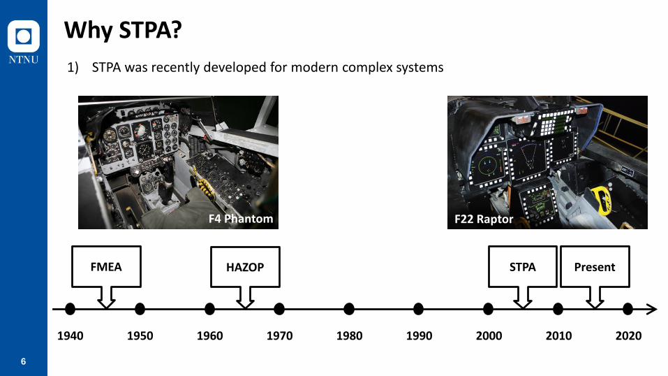
Why STPA?
6
1940 1950 1960 20101970 1980 1990 2000 2020
HAZOPFMEA Present
F4 Phantom F22 Raptor
STPA
1) STPA was recently developed for modern complex systems
Why STPA?

7
2) STPA is a top-down approach: analysis can be conducted from the beginning of a project
Design process
System requirement
Basicscheme/spec.
Concept design
Detaildesign
Productiondesign
Construction
FMEA
STPA
Finding flaws too late may cause significant costs
Identifying flaws in early stage can save unnecessary costs
Why STPA?
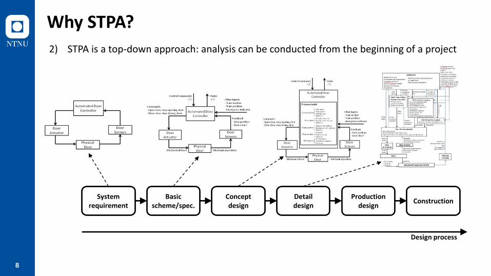
8
Design process
System requirement
Basicscheme/spec.
Concept design
Detaildesign
Productiondesign
Construction
2) STPA is a top-down approach: analysis can be conducted from the beginning of a project
Why STPA?
9
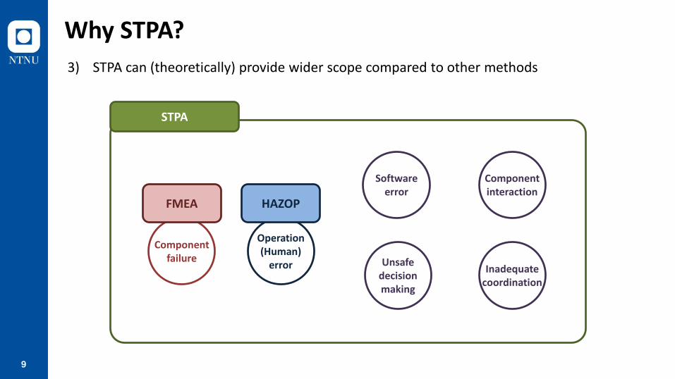
3) STPA can (theoretically) provide wider scope compared to other methods
STPA
Operation(Human)
error
Componentfailure
FMEA HAZOP
Softwareerror
Unsafedecisionmaking
Componentinteraction
Inadequatecoordination
Why STPA?

10
3) STPA can (theoretically) provide wider scope compared to other methods
Why STPA?
U.S. Missile Defence System (Pereira et al. 2006)
o The system had been subjected to standard hazard analysis methods, but one more
additional analysis was required
o STPA found so many flaws (by two persons for only three month analysis),
so that the deployment was delayed for six months to fix them

11
Why STPA?
Japanese Aerospace Exploration Agency (JAXA) (Ishimatsu et al. 2014)
o JAXA used STPA experimentally on their unmanned spacecraft
o STPA found everything identified in fault tree analysis
o STPA found additional hazardous scenarios related to system design flaws, software errors,
hazardous interactions, etc.
3) STPA can (theoretically) provide wider scope compared to other methods
12
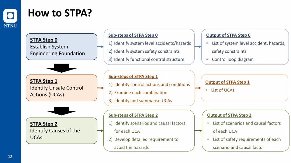
How to STPA?
STPA Step 0Establish System Engineering Foundation
STPA Step 1Identify Unsafe Control Actions (UCAs)
STPA Step 2Identify Causes of the UCAs
Sub-steps of STPA Step 0
1) Identify system level accidents/hazards
2) Identify system safety constraints
3) Identify functional control structure
Sub-steps of STPA Step 2
1) Identify scenarios and causal factors
for each UCA
2) Develop detailed requirement to
avoid the hazards
Output of STPA Step 0
• List of system level accident, hazards,
safety constraints
• Control loop diagram
Output of STPA Step 2
• List of scenarios and causal factors
of each UCA
• List of safety requirements of each
scenario and causal factor
Output of STPA Step 1
• List of UCAs
Sub-steps of STPA Step 1
1) Identify control actions and conditions
2) Examine each combination
3) Identify and summarise UCAs

13
STPA Studies in RAMS Group

14
STPA Studies in RAMS Group
• Subsea Gatebox (prioritization) – Master thesis (Nanda)
• Subsea Gatebox (post process) – Journal paper (Juntao)
• Isolation of subsea wells – OTC 2018
• Subsea gas compression – ESREL 2018
• To be continued…
• Autonomous ship (pre-screening) – Master thesis (Jiahui)
• Dynamic positioning system in Arctic condition – ESREL 2018 (with KRISO)
• Securing maintenance are – Master thesis (Sunniva)

15
Description of the Papers
Title: Application of Systems-Theoretic Process Analysis to a Subsea Gas Compression System
Title: Application of Systems-Theoretic Process Analysisto the isolation of subsea wells
ESREL 2018 OTC 2018
Main Objective
Discuss opportunities and challenges of the application of STPA to subsea systems
Focus: Subsea processing system
(Extend the discussion to the general
use of STPA)
Focus: Subsea safety system
(More focus on specific features
of subsea systems)

16
STPA to Subsea Gas Compression
ESREL 2018
17
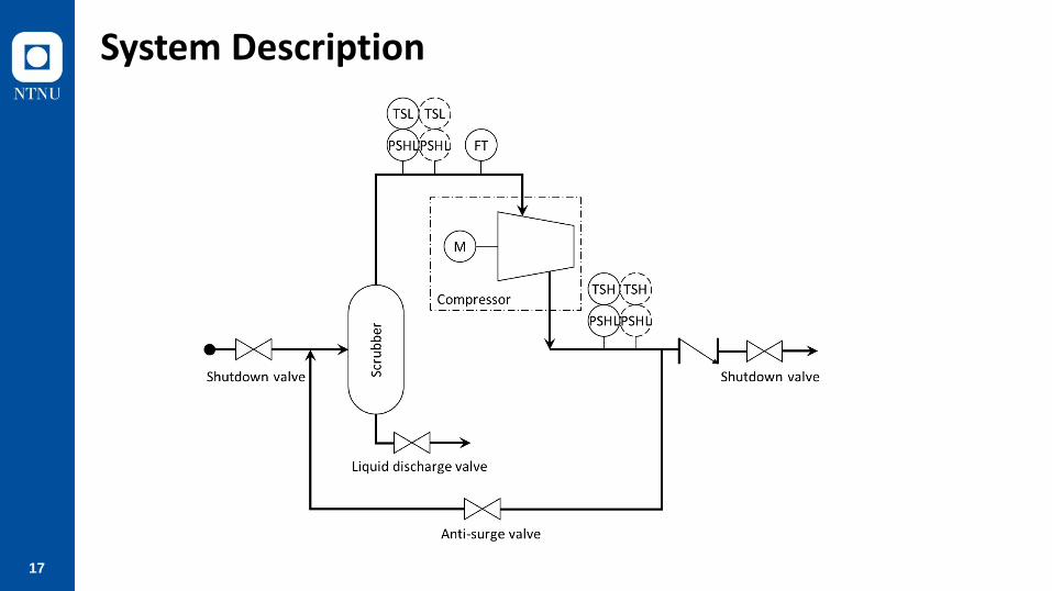
System Description
18
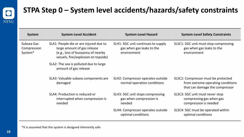
STPA Step 0 – System level accidents/hazards/safety constraints
System System-Level Accident System-Level Hazard System-Level Safety Constraints
Subsea Gas Compression System*
SLA1: People die or are injured due to large amount of gas release (e.g., loss of buoyancy of nearby vessels, fire/explosion on topside)
SLH1: SGC unit continues to supply gas when gas leaks to the environment
SLSC1: SGC unit must stop compressing gas when gas leaks to the environment
SLA2: The sea is polluted due to large amount of gas release
SLA3: Valuable subsea components are damaged
SLH2: Compressor operates outside normal operation conditions
SLSC2: Compressor must be protected from extreme operating conditions that can damage the compressor
SLA4: Production is reduced or interrupted when compression is needed
SLH3: SGC unit stops compressing gas when compression is needed
SLSC3: SGC unit must never stop compressing gas when gas compression is needed
SLH4: Compressor operates outside optimal conditions
SLSC4: SGC must be operated within optimal conditions
*It is assumed that the system is designed inherently safe
19
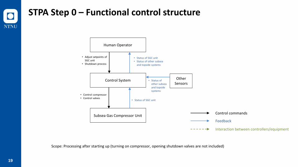
Human Operator
Control System
Interaction between controllers/equipment
Feedback
Control commands
Other Sensors
• Status of other subseaand topsidesystems
Subsea Gas Compressor Unit
• Status of SGC unit
Scope: Processing after starting up (turning on compressor, opening shutdown valves are not included)
• Control compressor• Control valves
• Status of SGC unit• Status of other subsea
and topside systems
• Adjust setpoints of SGC unit
• Shutdown process
STPA Step 0 – Functional control structure

20
• Status of other topside systems
• Speed up/downcomp.
• Tripcomp.
• Status of SGC unit• Status of other subsea
and topside systems
• Adjust setpointsof SGC unit
• Shutdown process Control System
• Shutdownprocess
• Open/close LDV• Open/close ASV
• Close SDVs
Subsea Gas CompressorUnit
• Open/close LDV• Open/close ASV• Close SDVs
SDVsposition
CloseSDVs
ASVposition
Open/close ASV
LDVposition
Open/closeLDV
• Compressor inlet temp.• Compressor inlet press.• Compressor inlet flow• Compressor outlet temp.• Compressor outlet press.• Scrubber level
SCM/SEM
SDVs ASV LDV Sensors
Human Operator
Other Topside Sensors
• Status of SGC• SDVs / ASV/ LDV position• Compressor inlet/outlet flow/temp./press.• Scrubber level• Status of other subsea systems
• Status of other subsea systems Other Subsea
Sensors
• Status of SGC unit andother subsea systems
• Status of SGC unit andother subsea systems
SCU
Abbreviation
• VSD: Variable Speed Drive
• PCS: Process Control System
• PSD: Process Shutdown
• SCU: Subsea Control Unit
• SCM: Subsea Control Module
• SEM: Subsea Electronic Module
• SGC: Subsea Gas Compressor
• SDV: Shutdown Valve
• ASV: Anti-Surge Valve
• LDV: Liquid Discharge Valve
Statusof SGC
• Speed up/downcomp.
• Comp. speed
SGC
VSD PSD System
• Trip compressor
PCS
STPA Step 0 – Functional control structure
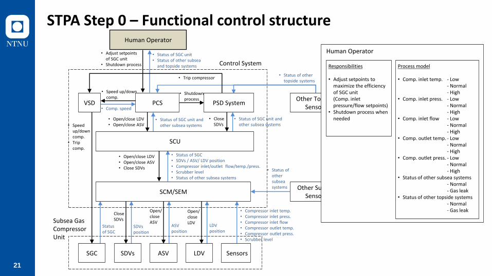
21
• Status of other topside systems
• Speed up/downcomp.
• Tripcomp.
• Status of SGC unit• Status of other subsea
and topside systems
• Adjust setpointsof SGC unit
• Shutdown process Control System
• Shutdownprocess
• Open/close LDV• Open/close ASV
• Close SDVs
Subsea Gas CompressorUnit
• Open/close LDV• Open/close ASV• Close SDVs
SDVsposition
CloseSDVs
ASVposition
Open/close ASV
LDVposition
Open/closeLDV
• Compressor inlet temp.• Compressor inlet press.• Compressor inlet flow• Compressor outlet temp.• Compressor outlet press.• Scrubber level
SCM/SEM
SDVs ASV LDV Sensors
Human Operator
Other Topside Sensors
• Status of SGC• SDVs / ASV/ LDV position• Compressor inlet/outlet flow/temp./press.• Scrubber level• Status of other subsea systems
• Status of other subsea systems Other Subsea
Sensors
• Status of SGC unit andother subsea systems
• Status of SGC unit andother subsea systems
SCU
Statusof SGC
• Speed up/downcomp.
• Comp. speed
SGC
VSD PSD System
• Trip compressor
PCS
Human Operator
Responsibilities
• Adjust setpoints tomaximize the efficiency of SGC unit(Comp. inlet pressure/flow setpoints)
• Shutdown process when needed
Process model
• Comp. inlet temp. - Low- Normal- High
• Comp. inlet press. - Low- Normal- High
• Comp. inlet flow - Low- Normal- High
• Comp. outlet temp. - Low- Normal- High
• Comp. outlet press. - Low- Normal- High
• Status of other subsea systems- Normal- Gas leak
• Status of other topside systems- Normal- Gas leak
STPA Step 0 – Functional control structure

22
• Status of other topside systems
• Speed up/downcomp.
• Tripcomp.
• Status of SGC unit• Status of other subsea
and topside systems
• Adjust setpointsof SGC unit
• Shutdown process Control System
• Shutdownprocess
• Open/close LDV• Open/close ASV
• Close SDVs
Subsea Gas CompressorUnit
• Open/close LDV• Open/close ASV• Close SDVs
SDVsposition
CloseSDVs
ASVposition
Open/close ASV
LDVposition
Open/closeLDV
• Compressor inlet temp.• Compressor inlet press.• Compressor inlet flow• Compressor outlet temp.• Compressor outlet press.• Scrubber level
SCM/SEM
SDVs ASV LDV Sensors
Human Operator
Other Topside Sensors
• Status of SGC• SDVs / ASV/ LDV position• Compressor inlet/outlet flow/temp./press.• Scrubber level• Status of other subsea systems
• Status of other subsea systems Other Subsea
Sensors
• Status of SGC unit andother subsea systems
• Status of SGC unit andother subsea systems
SCU
Statusof SGC
• Speed up/downcomp.
• Comp. speed
SGC
VSD PSD System
• Trip compressor
PCS
PCS
Responsibilities
• Deliver PSD commandfrom human operatorto PSD system
• Automatically adjustcompressor speed
• Automatically open/close LDV
• Automatically open/close ASV
Process model
• Setpoints - Optimal- Not optimal
• Comp. inlet temp. - Low- Normal- High
• Comp. inlet press. - Low- Normal- High
• Comp. inlet flow - Low- Normal- High
• Comp. outlet temp. - Low- Normal- High
• Comp. outlet press. - Low- Normal- High
• Scrubber level - Low- Normal- High
STPA Step 0 – Functional control structure
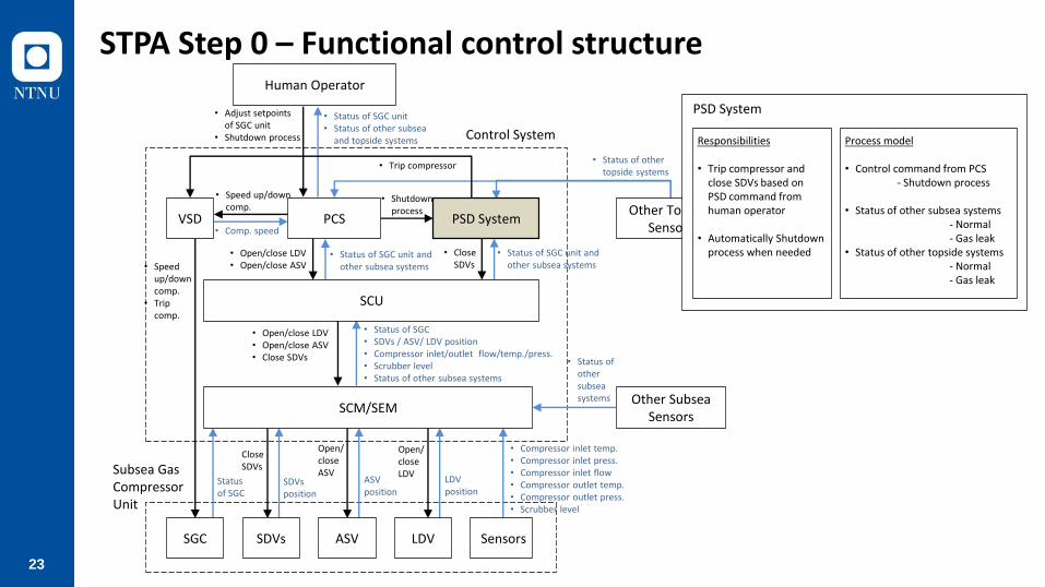
23
• Status of other topside systems
• Speed up/downcomp.
• Tripcomp.
• Status of SGC unit• Status of other subsea
and topside systems
• Adjust setpointsof SGC unit
• Shutdown process Control System
• Shutdownprocess
• Open/close LDV• Open/close ASV
• Close SDVs
Subsea Gas CompressorUnit
• Open/close LDV• Open/close ASV• Close SDVs
SDVsposition
CloseSDVs
ASVposition
Open/close ASV
LDVposition
Open/closeLDV
• Compressor inlet temp.• Compressor inlet press.• Compressor inlet flow• Compressor outlet temp.• Compressor outlet press.• Scrubber level
SCM/SEM
SDVs ASV LDV Sensors
Human Operator
Other Topside Sensors
• Status of SGC• SDVs / ASV/ LDV position• Compressor inlet/outlet flow/temp./press.• Scrubber level• Status of other subsea systems
• Status of other subsea systems Other Subsea
Sensors
• Status of SGC unit andother subsea systems
• Status of SGC unit andother subsea systems
SCU
Statusof SGC
• Speed up/downcomp.
• Comp. speed
SGC
VSD PSD System
• Trip compressor
PCS
PSD System
Responsibilities
• Trip compressor and close SDVs based on PSD command from human operator
• Automatically Shutdown process when needed
Process model
• Control command from PCS- Shutdown process
• Status of other subsea systems- Normal- Gas leak
• Status of other topside systems- Normal- Gas leak
STPA Step 0 – Functional control structure

24
• Status of other topside systems
• Speed up/downcomp.
• Tripcomp.
• Status of SGC unit• Status of other subsea
and topside systems
• Adjust setpointsof SGC unit
• Shutdown process Control System
• Shutdownprocess
• Open/close LDV• Open/close ASV
• Close SDVs
Subsea Gas CompressorUnit
• Open/close LDV• Open/close ASV• Close SDVs
SDVsposition
CloseSDVs
ASVposition
Open/close ASV
LDVposition
Open/closeLDV
• Compressor inlet temp.• Compressor inlet press.• Compressor inlet flow• Compressor outlet temp.• Compressor outlet press.• Scrubber level
SCM/SEM
SDVs ASV LDV Sensors
Human Operator
Other Topside Sensors
• Status of SGC• SDVs / ASV/ LDV position• Compressor inlet/outlet flow/temp./press.• Scrubber level• Status of other subsea systems
• Status of other subsea systems Other Subsea
Sensors
• Status of SGC unit andother subsea systems
• Status of SGC unit andother subsea systems
SCU
Statusof SGC
• Speed up/downcomp.
• Comp. speed
SGC
VSD PSD System
• Trip compressor
PCS
VSD
Responsibilities
• Deliver “Speed up/down” and “Trip” command to SGC
Process model
• Control command from PCS- Speed up- Speed down
• Control command from PSD- Trip compressor
STPA Step 0 – Functional control structure

25
• Status of other topside systems
• Speed up/downcomp.
• Tripcomp.
• Status of SGC unit• Status of other subsea
and topside systems
• Adjust setpointsof SGC unit
• Shutdown process Control System
• Shutdownprocess
• Open/close LDV• Open/close ASV
• Close SDVs
Subsea Gas CompressorUnit
• Open/close LDV• Open/close ASV• Close SDVs
SDVsposition
CloseSDVs
ASVposition
Open/close ASV
LDVposition
Open/closeLDV
• Compressor inlet temp.• Compressor inlet press.• Compressor inlet flow• Compressor outlet temp.• Compressor outlet press.• Scrubber level
SCM/SEM
SDVs ASV LDV Sensors
Human Operator
Other Topside Sensors
• Status of SGC• SDVs / ASV/ LDV position• Compressor inlet/outlet flow/temp./press.• Scrubber level• Status of other subsea systems
• Status of other subsea systems Other Subsea
Sensors
• Status of SGC unit andother subsea systems
• Status of SGC unit andother subsea systems
SCU
Statusof SGC
• Speed up/downcomp.
• Comp. speed
SGC
VSD PSD System
• Trip compressor
PCS
SCU
Responsibilities
• Deliver control commands from PCS and PSD system to SCM/SEM
Process model
• Control commands from PCS- Open/close LDV- Open/close ASV
• Control commands from PSD sys.- Close SDVs
STPA Step 0 – Functional control structure
26
• Status of other topside systems
• Speed up/downcomp.
• Tripcomp.
• Status of SGC unit• Status of other subsea
and topside systems
• Adjust setpointsof SGC unit
• Shutdown process Control System
• Shutdownprocess
• Open/close LDV• Open/close ASV
• Close SDVs
Subsea Gas CompressorUnit
• Open/close LDV• Open/close ASV• Close SDVs
SDVsposition
CloseSDVs
ASVposition
Open/close ASV
LDVposition
Open/closeLDV
• Compressor inlet temp.• Compressor inlet press.• Compressor inlet flow• Compressor outlet temp.• Compressor outlet press.• Scrubber level
SCM/SEM
SDVs ASV LDV Sensors
Human Operator
Other Topside Sensors
• Status of SGC• SDVs / ASV/ LDV position• Compressor inlet/outlet flow/temp./press.• Scrubber level• Status of other subsea systems
• Status of other subsea systems Other Subsea
Sensors
• Status of SGC unit andother subsea systems
• Status of SGC unit andother subsea systems
SCU
Statusof SGC
• Speed up/downcomp.
• Comp. speed
SGC
VSD PSD System
• Trip compressor
PCS
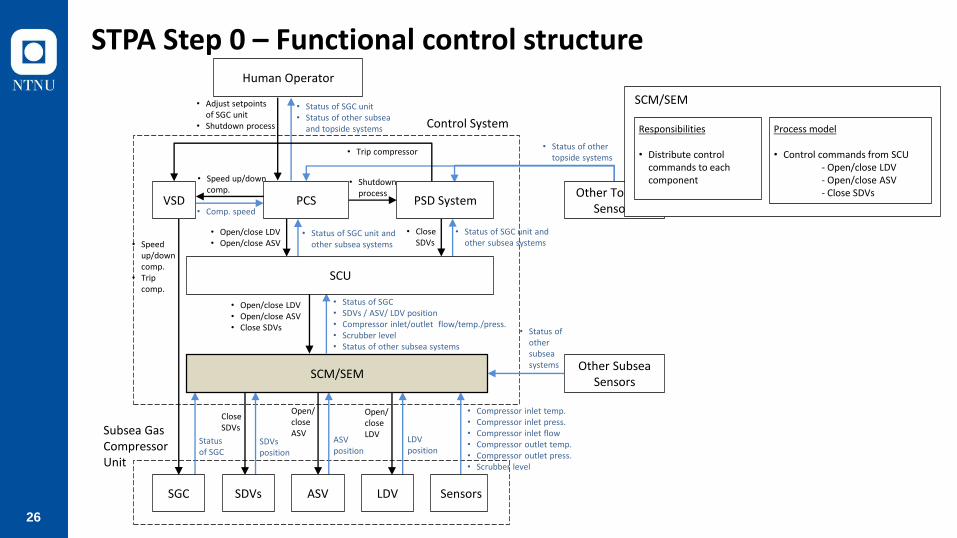
SCM/SEM
Responsibilities
• Distribute control commands to each component
Process model
• Control commands from SCU- Open/close LDV- Open/close ASV- Close SDVs
STPA Step 0 – Functional control structure

27
STPA Step 1 – Identifying UCAs

28
STPA Step 1 – Identifying UCAs
Controller : PCS
No Control Action
Condition Unsafe Control Actions?
Scrubber level Not provided Provided Too early Too late Too short Too long
1 Open LDV High
2 Normal
3 Low
4 Close LDV High
5 Normal
6 Low
Open LDV
Unsafe Safe Unsafe UnsafeSafe SafeSafe Safe Safe Safe Safe Safe
Safe N/A N/A N/A N/AUnsafe

29
STPA Step 1 – Identifying UCAs
Controller : PCS
No Control Action
Condition Unsafe Control Actions?
Scrubber level Not provided Provided Too early Too late Too short Too long
1 Open LDV High Unsafe [H2] Safe Safe Unsafe [H2] Unsafe [H2] Safe
2 Normal Safe Safe Safe Safe Safe Safe
3 Low Safe Unsafe [H2] N/A N/A N/A N/A
4 Close LDV High Safe Unsafe [H2] N/A N/A N/A N/A
5 Normal Safe Safe Safe Safe Safe Safe
6 Low Unsafe [H2] Safe Safe Unsafe [H2] Unsafe [H2] Safe
UCA.PCS.LDV.001: Open LDV command is not provided when scrubber level is high
UCA.PCS.LDV.002: Open LDV command is provided too late when scrubber level is high
UCA.PCS.LDV.003: Open LDV command is provided too short when scrubber level is high
UCA.PCS.LDV.004: Open LDV command is provided when scrubber level is low
UCA.PCS.LDV.005: Close LDV command is provided when scrubber level is high

30
STPA Step 2: Identifying Causes of UCAs and Safety Constrains
UCA-PCS001: Open LDV command is not provided when scrubber level is high
Scenario Associated Causal Factors Safety Constraints
PCS receives wrong measurement of scrubber level
Drift of scrubber LT SC-PCS001-01: Scrubber LT must be calibrated periodically SC-PCS001-02: Scrubber LT must have 2oo3 configuration
PCS receives no measurement of scrubber level
No power supply to scrubber LT
SC-PCS001-03: PCS must generate an alarm when no signal is received from scrubber LT
SC-PCS001-04: Scrubber LT must be connected to UPS
Broken signal wires from scrubber LT to PCS
SC-PCS001-03: PCS must generate an alarm when no signal is received from scrubber LT
SC-PCS001-05: Signal wires must be inspected periodically
PCS receives correct measurement, but PCS does not provide open LDV command
Wrong logic inside PCS SC-PCS001-06: PCS logic to generate “open LDV” command must be fully tested during commissioning period

31
Results
• Status of other topside systems
• Speed up/downcomp.
• Tripcomp.
• Status of SGC unit• Status of other subsea
and topside systems
• Adjust setpointsof SGC unit
• Shutdown process Control System
• Shutdownprocess
• Open/close LDV• Open/close ASV
• Close SDVs
Subsea Gas CompressorUnit
• Open/close LDV• Open/close ASV• Close SDVs
SDVsposition
CloseSDVs
ASVposition
Open/close ASV
LDVposition
Open/closeLDV
• Compressor inlet temp.• Compressor inlet press.• Compressor inlet flow• Compressor outlet temp.• Compressor outlet press.• Scrubber level
SCM/SEM
SDVs ASV LDV Sensors
Human Operator
Other Topside Sensors
• Status of SGC• SDVs / ASV/ LDV position• Compressor inlet/outlet flow/temp./press.• Scrubber level• Status of other subsea systems
• Status of other subsea systems Other Subsea
Sensors
• Status of SGC unit andother subsea systems
• Status of SGC unit andother subsea systems
SCU
Statusof SGC
• Speed up/downcomp.
• Comp. speed
SGC
VSD PSD System
• Trip compressor
PCS
10
30 1215
31
31
129 UCAs

32
129 UCAs
• Status of other topside systems
• Speed up/downcomp.
• Tripcomp.
• Status of SGC unit• Status of other subsea
and topside systems
• Adjust setpointsof SGC unit
• Shutdown process Control System
• Shutdownprocess
• Open/close LDV• Open/close ASV
• Close SDVs
Subsea Gas CompressorUnit
• Open/close LDV• Open/close ASV• Close SDVs
SDVsposition
CloseSDVs
ASVposition
Open/close ASV
LDVposition
Open/closeLDV
• Compressor inlet temp.• Compressor inlet press.• Compressor inlet flow• Compressor outlet temp.• Compressor outlet press.• Scrubber level
SCM/SEM
SDVs ASV LDV Sensors
Human Operator
Other Topside Sensors
• Status of SGC• SDVs / ASV/ LDV position• Compressor inlet/outlet flow/temp./press.• Scrubber level• Status of other subsea systems
• Status of other subsea systems Other Subsea
Sensors
• Status of SGC unit andother subsea systems
• Status of SGC unit andother subsea systems
SCU
Statusof SGC
• Speed up/downcomp.
• Comp. speed
SGC
VSD PSD System
• Trip compressor
PCS30 12
31
31
H1:18 (14%)
H2: 66 (51%)H3:9 (7%)
H4:36 (28%)
Results
H1: Gas leak (human & Env.)H2: Compressor damageH3: Unnecessary production stopH4: Low efficiency
10
15

33
Discussion
STPA Hazards (UCAs)Causes/Scenarios/
Safety Requirements
Functionalcontrol structure
HAZOP
FMECA
Brainstorming
1) Identifying Causes, Scenarios, and Safety Requirements
Systematic approach
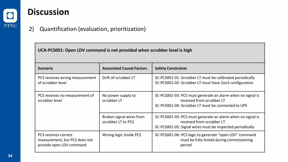
34
Discussion
2) Quantification (evaluation, prioritization)
UCA-PCS001: Open LDV command is not provided when scrubber level is high
Scenario Associated Causal Factors Safety Constraints
PCS receives wrong measurement of scrubber level
Drift of scrubber LT SC-PCS001-01: Scrubber LT must be calibrated periodically SC-PCS001-02: Scrubber LT must have 2oo3 configuration
PCS receives no measurement of scrubber level
No power supply to scrubber LT
SC-PCS001-03: PCS must generate an alarm when no signal is received from scrubber LT
SC-PCS001-04: Scrubber LT must be connected to UPS
Broken signal wires from scrubber LT to PCS
SC-PCS001-03: PCS must generate an alarm when no signal is received from scrubber LT
SC-PCS001-05: Signal wires must be inspected periodically
PCS receives correct measurement, but PCS does not provide open LDV command
Wrong logic inside PCS SC-PCS001-06: PCS logic to generate “open LDV” command must be fully tested during commissioning period

35
STPA to Isolation of Subsea Wells
OTC 2018

36
System Description

37
STPA Step 0 – System level accidents/hazards/safety constraints
System Accident Hazard Safety Constraints
Emergency Shut Down (ESD) System – Isolation of Subsea Well
SLA1: People die or are injured due to fire and/or explosion
SLH1: Hydrocarbons are released at manned platform or inside safety zone, and ignite
SLSC1: Hydrocarbons must never be released at manned platform or inside safetyzone
SLSC2: Released hydrocarbons must never be ignited
SLA2: The sea is polluted due to hydrocarbon release
SLH2: ESD system is not able to shut down subsea wells when hydrocarbons are released to the environment
SLSC3: ESD system must always shut down subsea wells when hydrocarbons are released to the environment
SLA3: Production is interrupted unnecessarily
SLH3: ESD system shuts down subsea wells when hydrocarbons are not released to the environment
SLSC4: ESD system must never shut down subsea wells when there is no hydrocarbon release
38
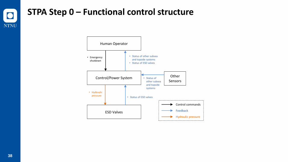
STPA Step 0 – Functional control structure
Human Operator
Control/Power System
Feedback
Control commands
Other Sensors
• Status of other subseaand topsidesystems
ESD Valves
• Status of ESD valves
• Hydraulic pressure
• Status of other subseaand topside systems
• Status of ESD valves
• Emergencyshutdown
Hydraulic pressure

39
STPA Step 0 – Functional control structure
• Status of other topside systems
• Status of othersubsea systems
• Status of ESD valves
Control/Power System
• Bleed down hydraulic pressure
• Cut off elec. power
ESDValves
• Pressure of DHSV• Pressure of PMV• Pressure of PWV• Pressure of CIV
Human Operator
Other Topside Sensors
• Status of other subsea systems Other Subsea
Sensors
Abbreviation
• SAS: Safety Automation System
• HPU: Hydraulic Power Unit
• EPU: Electric Power Unit
• SCM: Subsea Control Module
• DCV: Direction Control Valve
• ESD: Emergency Shutdown
• DHSV: Down Hole Safety Valve
• PMW: Production Master Valve
• PWV: Production Wing Valve
• CIV: Chemical Injection Valve
• SEM: Subsea Electronic Module
HPU
SCM
Hydraulic pressure Electric power
Dump DCV
DHSV DCV
PMV DCV
PWV DCV
CIV DCV
DHSV PMV PWV CIV Sensors
Hydraulicpressure
Hydraulicpressure
Hydraulicpressure
Hydraulicpressure
• Status of other subseaand topside systems
• Status of ESD valves
SEM
• Bleed down hyd. pressure
• Cut off electricalpower
SASESD
EPU
• Emergencyshutdown
Feedback
Control commands
Hydraulic pressure
Hydraulic pressure
40
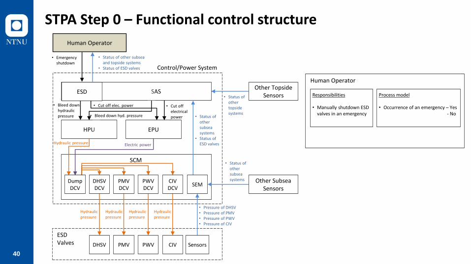
STPA Step 0 – Functional control structure
• Status of other topside systems
• Status of othersubsea systems
• Status of ESD valves
• Emergencyshutdown
Control/Power System
• Bleed down hydraulic pressure
• Cut off elec. power
ESDValves
• Pressure of DHSV• Pressure of PMV• Pressure of PWV• Pressure of CIV
Human Operator
Other Topside Sensors
• Status of other subsea systems Other Subsea
Sensors
HPU
SCM
Hydraulic pressure Electric power
Dump DCV
DHSV DCV
PMV DCV
PWV DCV
CIV DCV
DHSV PMV PWV CIV Sensors
Hydraulicpressure
Hydraulicpressure
Hydraulicpressure
Hydraulicpressure
• Status of other subseaand topside systems
• Status of ESD valves
SEM
• Bleed down hyd. pressure
• Cut off electricalpower
SASESD
EPU
Human Operator
Responsibilities
• Manually shutdown ESD valves in an emergency
Process model
• Occurrence of an emergency – Yes- No

41
STPA Step 0 – Functional control structure
SAS
Responsibilities
• Automatically shutdown ESD valves when pre-defined abnormal conditions are detected
Process model
• Gas at HVAC inlet - Detected- Not detected
• Gas in non-hazardous area- Detected- Not detected
• Gas in hazardous area- Detected- Not detected
• Fire in hazardous area- Detected- Not detected
• Gas/water heat exchanger tube - Ruptured- Normal
• Status of other topside systems
• Status of othersubsea systems
• Status of ESD valves
• Emergencyshutdown
Control/Power System
• Bleed down hydraulic pressure
• Cut off elec. power
ESDValves
• Pressure of DHSV• Pressure of PMV• Pressure of PWV• Pressure of CIV
Human Operator
Other Topside Sensors
• Status of other subsea systems Other Subsea
Sensors
HPU
SCM
Hydraulic pressure Electric power
Dump DCV
DHSV DCV
PMV DCV
PWV DCV
CIV DCV
DHSV PMV PWV CIV Sensors
Hydraulicpressure
Hydraulicpressure
Hydraulicpressure
Hydraulicpressure
• Status of other subseaand topside systems
• Status of ESD valves
SEM
• Bleed down hyd. pressure
• Cut off electricalpower
SASESD
EPU

42
STPA Step 0 – Functional control structure
ESD
Responsibilities
• Shutdown ESD valves when human operator provides emergency shutdown command
Process model
• Control command from human- Emergency shutdown- None
• Status of other topside systems
• Status of othersubsea systems
• Status of ESD valves
• Emergencyshutdown
Control/Power System
• Bleed down hydraulic pressure
• Cut off elec. power
ESDValves
• Pressure of DHSV• Pressure of PMV• Pressure of PWV• Pressure of CIV
Human Operator
Other Topside Sensors
• Status of other subsea systems Other Subsea
Sensors
HPU
SCM
Hydraulic pressure Electric power
Dump DCV
DHSV DCV
PMV DCV
PWV DCV
CIV DCV
DHSV PMV PWV CIV Sensors
Hydraulicpressure
Hydraulicpressure
Hydraulicpressure
Hydraulicpressure
• Status of other subseaand topside systems
• Status of ESD valves
SEM
• Bleed down hyd. pressure
• Cut off electricalpower
SASESD
EPU

43
STPA Step 0 – Functional control structure
HPU
Responsibilities
• Bleed down hydraulic pressure when ESD or SAS provides bleed down hydraulic pressure command
Process model
• Control command from ESD or SAS- Bleed down hydraulic
pressure- None
EPU
Responsibilities
• Cut off electrical power when Human Operator or SAS provides cut off electrical power command
Process model
• Control command from ESD or SAS- Cut off electric power- None
• Status of other topside systems
• Status of othersubsea systems
• Status of ESD valves
• Emergencyshutdown
Control/Power System
• Bleed down hydraulic pressure
• Cut off elec. power
ESDValves
• Pressure of DHSV• Pressure of PMV• Pressure of PWV• Pressure of CIV
Human Operator
Other Topside Sensors
• Status of other subsea systems Other Subsea
Sensors
HPU
SCM
Hydraulic pressure Electric power
Dump DCV
DHSV DCV
PMV DCV
PWV DCV
CIV DCV
DHSV PMV PWV CIV Sensors
Hydraulicpressure
Hydraulicpressure
Hydraulicpressure
Hydraulicpressure
• Status of other subseaand topside systems
• Status of ESD valves
SEM
• Bleed down hyd. pressure
• Cut off electricalpower
SASESD
EPU
44
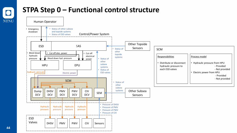
STPA Step 0 – Functional control structure
• Status of other topside systems
• Status of othersubsea systems
• Status of ESD valves
• Emergencyshutdown
Control/Power System
• Bleed down hydraulic pressure
• Cut off elec. power
ESDValves
• Pressure of DHSV• Pressure of PMV• Pressure of PWV• Pressure of CIV
Human Operator
Other Topside Sensors
• Status of other subsea systems Other Subsea
Sensors
HPU
SCM
Hydraulic pressure Electric power
Dump DCV
DHSV DCV
PMV DCV
PWV DCV
CIV DCV
DHSV PMV PWV CIV Sensors
Hydraulicpressure
Hydraulicpressure
Hydraulicpressure
Hydraulicpressure
• Status of other subseaand topside systems
• Status of ESD valves
SEM
• Bleed down hyd. pressure
• Cut off electricalpower
SASESD
EPU
SCM
Responsibilities
• Distribute or disconnect hydraulic pressure to each ESD valves
Process model
• Hydraulic pressure from HPU - Provided- Not provided
• Electric power from HPU- Provided- Not provided

45
STPA Step 1 – Identifying UCAs
Controller : SAS
No Control Action
Condition Unsafe Control Actions?
Pre-defined abnormal conditions
Not provided Provided Too early Too late Too short Too long
1 Bleed down hydraulic pressure
Occurred Unsafe [H1,H2] Safe N/A Unsafe [H1,H2] Unsafe [H1,H2] N/A
2 Not occurred Safe Unsafe [H3] N/A N/A N/A N/A
3 Cut off electrical power
Occurred Unsafe [H1,H2] Safe N/A Unsafe [H1,H2] Unsafe [H1,H2] N/A
4 Not occurred Safe Unsafe [H3] N/A N/A N/A N/A

46
STPA Step 1 – Identifying UCAs
No UCAs
UCA.HOP.001 Human Operator does not provide emergency shutdown command when an emergency occurs [H1,H2]
UCA.HOP.002 Human Operator provides emergency shutdown command too late when an emergency occurs [H1,H2]
UCA.HOP.003 Human Operator provides emergency shutdown command when an emergency does not occur [H3]
UCA.ESD.001 ESD does not provide bleed down hydraulic pressure command when Human Operator provides emergency shutdown command [H1,H2]
UCA.ESD.002 ESD provides bleed down hydraulic pressure command too late when Human Operator provides emergency shutdown command [H1,H2]
UCA.ESD.003 ESD provides bleed down hydraulic pressure command too short when Human Operator provides emergency shutdown command [H1,H2]
UCA.ESD.004 ESD provides bleed down hydraulic pressure command when Human Operator does not provide emergency shutdown command [H3]
UCA.ESD.005 ESD does not provide cut off electrical power command when Human Operator provides emergency shutdown command [H1,H2]
UCA.ESD.006 ESD provides cut off electrical power command too late when Human Operator provides emergency shutdown command [H1,H2]
UCA.ESD.007 ESD provides cut off electrical power command too short when Human Operator provides emergency shutdown command [H1,H2]
UCA.ESD.008 ESD provides cut off electrical power command when Human Operator does not provide emergency shutdown command [H3]
UCA.SAS.001 SAS does not provide bleed down hydraulic pressure command when pre-defined abnormal conditions are detected [H1,H2]
UCA.SAS.002 SAS provides bleed down hydraulic pressure command too late when pre-defined abnormal conditions are detected [H1,H2]
UCA.SAS.003 SAS provides bleed down hydraulic pressure command too short when pre-defined abnormal conditions are detected [H1,H2]
UCA.SAS.004 SAS provides bleed down hydraulic pressure command when pre-defined abnormal conditions are not detected [H3]
UCA.SAS.005 SAS does not provide cut off electrical power command when pre-defined abnormal conditions are detected [H1,H2]
UCA.SAS.006 SAS provides cut off electrical power command too late when pre-defined abnormal conditions are detected [H1,H2]
UCA.SAS.007 SAS provides cut off electrical power command too short when pre-defined abnormal conditions are detected [H1,H2]
UCA.SAS.008 SAS provides cut off electrical power command when pre-defined abnormal conditions are not detected [H3]
UCA.HPU.001 HPU provides hydraulic pressure when ESD or SAS provides bleed down hydraulic pressure command [H1,H2]
UCA.HPU.002 HPU does not provide hydraulic pressure too late when ESD or SAS provides bleed down hydraulic pressure command [H1,H2]
UCA.HPU.003 HPU does not provide hydraulic pressure too short when ESD or SAS provides bleed down hydraulic pressure command [H1,H2]
UCA.HPU.004 HPU does not provide hydraulic pressure when ESD or SAS does not provide bleed down hydraulic pressure command [H3]
UCA.EPU.001 EPU provides electric power when ESD or SAS provides cut off electrical power command [H1,H2]
UCA.EPU.002 EPU does not provide electric power too late when ESD or SAS provides cut off electrical power command [H1,H2]
UCA.EPU.003 EPU does not provide electric power too short when ESD or SAS provides cut off electrical power command [H1,H2]
UCA.EPU.004 EPU does not provide electric power when ESD or SAS does not provide cut off electrical power command [H3]
UCA.SCM.001 SCM does not distribute hydraulic pressure when hydraulic pressure or electric power is supplied [H3]
UCA.SCM.002 SCM distributes hydraulic pressure when hydraulic pressure or electric power is not supplied [H1,H2]
UCA.SCM.003 SCM does not distribute hydraulic pressure too late when hydraulic pressure or electric power is not supplied [H1,H2]

47
STPA Step 2: Identifying Causes of UCAs and Safety Constrains
UCA.SAS.001: SAS does not provide bleed down hydraulic pressure command when pre-defined abnormal conditions have occurred
ScenarioAssociated Causal Factors
Safety Constraints
SNR.SAS.001.02SAS receives no information about pre-defined conditions
Failure of sensors SC.SAS.001.02.01All sensors for pre-defined conditions must be tested periodicallySC.SAS.001.02.02All sensors for pre-defined conditions must have redundancy (e.g., 2oo3 configuration)
Broken signal wires between sensors and SAS
SC.SAS.001.02.03All signal wires for pre-defined conditions must be inspected periodicallySC.SAS.001.02.04SAS must generate an alarm when no signal is received from any sensors for pre-defined conditions
No power supply to sensors
SC.SAS.001.02.05All sensors for pre-defined conditions must be connected to redundant power supply or UPSSC.SAS.001.02.04SAS must generate an alarm when no signal is received from any sensors for pre-defined conditions

48
ResultsNo
UCA.HOP.001
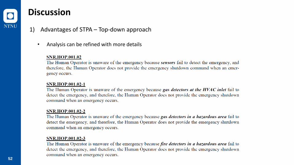
SNR.HOP.001.01 Human Operator receives wrong feedback from SAS due to sensor failure
SNR.HOP.001.02 Human Operator receives no feedback from SAS due to sensor failure
SNR.HOP.001.03 Human Operator receives no feedback from SAS due to communication cable failure
SNR.HOP.001.04 Human Operator receives no feedback from SAS due to loss of power supply
SNR.HOP.001.05 Human Operator receives wrong feedback from SAS due to software error inside SAS
SNR.HOP.001.06 Human Operator receives no feedback from SAS due to software error inside SAS
SNR.HOP.001.07 Human Operator receives no feedback from SAS due to HMI failure
SNR.HOP.001.08 Human Operator receives correct feedback from SAS, but does not provide command
UCA.HOP.002
SNR.HOP.002.01 Human Operator receives feedback from SAS too late due to sensor failure
SNR.HOP.002.02 Human Operator receives feedback from SAS too late due to software error inside SAS
SNR.HOP.002.03 Human Operator receives feedback from SAS in time, but provides control command too late
UCA.HOP.003
SNR.HOP.003.01 Human Operator receives wrong feedback from SAS due to sensor failure
SNR.HOP.003.02 Human Operator receives wrong feedback from SAS due to software error inside SAS
SNR.HOP.003.03 Human Operator receives correct feedback from SAS, but provides command
UCA.ESD.001
SNR.ESD.001.01 ESD does not receive control command from Human Operator due to cable failure
SNR.ESD.001.02 ESD does not receive control command from Human Operator due to loss of power supply
SNR.ESD.001.03 ESD receives control command from Human Operator, but does not provide control command due to ESD system failure
UCA.ESD.002
SNR.ESD.002.01 No possible scenario
UCA.ESD.003
SNR.ESD.003.01 No possible scenario
UCA.ESD.004
SNR.ESD.004.01 ESD provides control command due to short circuit
UCA.ESD.005
SNR.ESD.005.01 ESD does not receive control command from Human Operator due to cable failure
SNR.ESD.005.02 ESD does not receive control command from Human Operator due loss of power supply
SNR.ESD.005.03 ESD receives control command from Human Operator, but does not provide control command due to ESD system failure
UCA.ESD.006
SNR.ESD.006.01 No possible scenario
UCA.ESD.007
SNR.ESD.007.01 No possible scenario
UCA.ESD.008
SNR.ESD.008.01 ESD provides control command due to short circuit
UCA.SAS.001
SNR.SAS.001.01 SAS receives wrong feedback from sensors due to sensor failure
SNR.SAS.001.02 SAS receives no feedback from sensors due to sensor failure
SNR.SAS.001.03 SAS receives no feedback from sensors due to signal cable failure
SNR.SAS.001.04 SAS receives no feedback from sensors due to loss of power supply
SNR.SAS.001.05 SAS receives correct feedback from sensors, but does not provide command due to software error inside SAS
UCA.SAS.002
SNR.SAS.002.01 SAS receives feedback from sensors too late due to sensor failure
SNR.SAS.002.02 SAS receives feedback from sensors in time, but provides control command too late due to software error inside SAS
UCA.SAS.003
SNR.SAS.003.01 SAS stops providing bleed down commend too soon due to software error inside SAS
UCA.SAS.004
SNR.SAS.004.01 SAS receives wrong feedback from sensors due to sensor failure
SNR.SAS.004.02 SAS receives correct feedback from sensors, but provides command due to software error inside SAS
UCA.SAS.005
SNR.SAS.005.01 SAS receives wrong feedback from sensors due to sensor failure
SNR.SAS.005.02 SAS receives no feedback from sensors due to sensor failure
SNR.SAS.005.03 SAS receives no feedback from sensors due to signal cable failure
SNR.SAS.005.04 SAS receives no feedback from sensors due to loss of power supply
SNR.SAS.005.05 SAS receives correct feedback from sensors, but does not provide command due to software error inside SAS
UCA.SAS.006
SNR.SAS.006.01 SAS receives feedback from sensors too late due to sensor failure
SNR.SAS.006.02 SAS receives feedback from sensors in time, but provides control command too late due to software error inside SAS
UCA.SAS.007
SNR.SAS.007.01 SAS stops providing bleed down commend too soon due to software error inside SAS
UCA.SAS.008
SNR.SAS.008.01 SAS receives wrong feedback from sensors due to sensor failure
SNR.SAS.008.02 SAS receives correct feedback from sensors, but provides command due to software error inside SAS
UCA.HPU.001
SNR.HPU.001.01 HPU receives wrong command from ESD or SAS due to communication cable failre
SNR.HPU.001.02 HPU receives no command from ESD or SAS due to communication cable failure
SNR.HPU.001.03 HPU receives no command from ESD or SAS due to loss of power supply
SNR.HPU.001.04 HPU receives command from ESD or SAS, but provides hydraulic pressure due to software error inside HPU
SNR.HPU.001.05 HPU receives command from ESD or SAS, but provides hydraulic pressure due to solenoid valve faliure
UCA.HPU.002
SNR.HPU.002.01 HPU receives command from ESD or SAS too late due to communication cable failure
SNR.HPU.002.02 HPU receives command in time, but stop providing hydraulic pressure too late due to software error inside HPU
SNR.HPU.002.03 HPU receives command in time, but stop providing hydraulic pressure too late due to solenoid valve failure
UCA.HPU.003
SNR.HPU.003.01 HPU starts providing hydraulic pressure again due to software error inside HPU
SNR.HPU.003.02 HPU starts providing hydraulic pressure again due to solenoid valve failure
UCA.HPU.004
SNR.HPU.004.01 HPU receives wrong command from ESD or SAS due to communication cable failre
SNR.HPU.004.02 HPU does not receive command from ESD or SAS, but provides hydraulic pressure due to software error inside HPU
SNR.HPU.004.03 HPU does not receive command from ESD or SAS, but provides hydraulic pressure due to solenoid valve faliure
UCA.EPU.001
SNR.EPU.001.01 EPU receives wrong command from ESD or SAS due to communication cable failre
SNR.EPU.001.02 EPU receives no command from ESD or SAS due to communication cable failure
SNR.EPU.001.03 EPU receives no command from ESD or SAS due to loss of power supply
SNR.EPU.001.04 EPU receives command from ESD or SAS, but provides electric power due to software error inside EPU
SNR.EPU.001.05 EPU receives command from ESD or SAS, but provides electric power due to relay faliure
UCA.EPU.002
SNR.EPU.002.01 EPU receives command from ESD or SAS too late due to communication cable failure
SNR.EPU.002.02 EPU receives command in time, but stop providing electric power too late due to software error inside EPU
SNR.EPU.002.03 EPU receives command in time, but stop providing electric power too late due to relay failure
UCA.EPU.003
SNR.EPU.003.01 EPU starts providing hydraulic pressure again due to software error inside EPU
SNR.EPU.003.02 EPU starts providing hydraulic pressure again due to relay failure
UCA.EPU.004
SNR.EPU.004.01 EPU receives wrong command from ESD or SAS due to communication cable failre
SNR.EPU.004.02 EPU does not receive command from ESD or SAS, but provides electric power due to software error inside EPU
SNR.EPU.004.03 EPU does not receive command from ESD or SAS, but provides electric power due to relay faliure
UCA.SCM.001
SNR.SCM.001.01 Hydraulic leak
SNR.SCM.001.02 DCVs are clogged
UCA.SCM.002
SNR.SCM.002.01 No possible scenario
UCA.SCM.003
SNR.SCM.003.01 Dut to long distance between HPU and SCM
SCM does not distribute hydraulic pressure when hydraulic pressure or electric power is supplied [H3]
SCM distributes hydraulic pressure when hydraulic pressure or electric power is not supplied [H1,H2]
SCM does not distribute hydraulic pressure too late when hydraulic pressure or electric power is not supplied [H1,H2]
HPU does not provide hydraulic pressure too short when ESD or SAS provides bleed down hydraulic pressure command [H1,H2]
HPU does not provide hydraulic pressure when ESD or SAS does not provide bleed down hydraulic pressure command [H3]
EPU provides electric power when ESD or SAS provides cut off electrical power command [H1,H2]
EPU does not provide electric power too late when ESD or SAS provides cut off electrical power command [H1,H2]
EPU does not provide electric power too short when ESD or SAS provides cut off electrical power command [H1,H2]
EPU does not provide electric power when ESD or SAS does not provide cut off electrical power command [H3]
HPU does not provide hydraulic pressure too late when ESD or SAS provides bleed down hydraulic pressure command [H1,H2]
ESD provides cut off electrical power command too short when Human Operator provides emergency shutdown command [H1,H2]
ESD provides cut off electrical power command when Human Operator does not provide emergency shutdown command [H3]
SAS does not provide bleed down hydraulic pressure command when pre-defined abnormal conditions are detected [H1,H2]
SAS provides bleed down hydraulic pressure command too late when pre-defined abnormal conditions are detected [H1,H2]
SAS provides bleed down hydraulic pressure command too short when pre-defined abnormal conditions are detected [H1,H2]
SAS provides bleed down hydraulic pressure command when pre-defined abnormal conditions are not detected [H3]
SAS does not provide cut off electrical power command when pre-defined abnormal conditions are detected [H1,H2]
SAS provides cut off electrical power command too late when pre-defined abnormal conditions are detected [H1,H2]
SAS provides cut off electrical power command too short when pre-defined abnormal conditions are detected [H1,H2]
SAS provides cut off electrical power command when pre-defined abnormal conditions are not detected [H3]
HPU provides hydraulic pressure when ESD or SAS provides bleed down hydraulic pressure command [H1,H2]
ESD provides cut off electrical power command too late when Human Operator provides emergency shutdown command [H1,H2]
Contents
Human Operator does not provide emergency shutdown command when an emergency occurs [H1,H2]
Human Operator provides emergency shutdown command too late when an emergency occurs [H1,H2]
Human Operator provides emergency shutdown command when an emergency does not occur [H3]
ESD does not provide bleed down hydraulic pressure command when Human Operator provides emergency shutdown command [H1,H2]
ESD provides bleed down hydraulic pressure command too late when Human Operator provides emergency shutdown command [H1,H2]
ESD provides bleed down hydraulic pressure command too short when Human Operator provides emergency shutdown command [H1,H2]
ESD provides bleed down hydraulic pressure command when Human Operator does not provide emergency shutdown command [H3]
ESD does not provide cut off electrical power command when Human Operator provides emergency shutdown command [H1,H2]
No UCAs
UCA.HOP.001 Human Operator does not provide emergency shutdown command when an emergency occurs [H1,H2]
UCA.HOP.002 Human Operator provides emergency shutdown command too late when an emergency occurs [H1,H2]
UCA.HOP.003 Human Operator provides emergency shutdown command when an emergency does not occur [H3]
UCA.ESD.001 ESD does not provide bleed down hydraulic pressure command when Human Operator provides emergency shutdown command [H1,H2]
UCA.ESD.002 ESD provides bleed down hydraulic pressure command too late when Human Operator provides emergency shutdown command [H1,H2]
UCA.ESD.003 ESD provides bleed down hydraulic pressure command too short when Human Operator provides emergency shutdown command [H1,H2]
UCA.ESD.004 ESD provides bleed down hydraulic pressure command when Human Operator does not provide emergency shutdown command [H3]
UCA.ESD.005 ESD does not provide cut off electrical power command when Human Operator provides emergency shutdown command [H1,H2]
UCA.ESD.006 ESD provides cut off electrical power command too late when Human Operator provides emergency shutdown command [H1,H2]
UCA.ESD.007 ESD provides cut off electrical power command too short when Human Operator provides emergency shutdown command [H1,H2]
UCA.ESD.008 ESD provides cut off electrical power command when Human Operator does not provide emergency shutdown command [H3]
UCA.SAS.001 SAS does not provide bleed down hydraulic pressure command when pre-defined abnormal conditions are detected [H1,H2]
UCA.SAS.002 SAS provides bleed down hydraulic pressure command too late when pre-defined abnormal conditions are detected [H1,H2]
UCA.SAS.003 SAS provides bleed down hydraulic pressure command too short when pre-defined abnormal conditions are detected [H1,H2]
UCA.SAS.004 SAS provides bleed down hydraulic pressure command when pre-defined abnormal conditions are not detected [H3]
UCA.SAS.005 SAS does not provide cut off electrical power command when pre-defined abnormal conditions are detected [H1,H2]
UCA.SAS.006 SAS provides cut off electrical power command too late when pre-defined abnormal conditions are detected [H1,H2]
UCA.SAS.007 SAS provides cut off electrical power command too short when pre-defined abnormal conditions are detected [H1,H2]
UCA.SAS.008 SAS provides cut off electrical power command when pre-defined abnormal conditions are not detected [H3]
UCA.HPU.001 HPU provides hydraulic pressure when ESD or SAS provides bleed down hydraulic pressure command [H1,H2]
UCA.HPU.002 HPU does not provide hydraulic pressure too late when ESD or SAS provides bleed down hydraulic pressure command [H1,H2]
UCA.HPU.003 HPU does not provide hydraulic pressure too short when ESD or SAS provides bleed down hydraulic pressure command [H1,H2]
UCA.HPU.004 HPU does not provide hydraulic pressure when ESD or SAS does not provide bleed down hydraulic pressure command [H3]
UCA.EPU.001 EPU provides electric power when ESD or SAS provides cut off electrical power command [H1,H2]
UCA.EPU.002 EPU does not provide electric power too late when ESD or SAS provides cut off electrical power command [H1,H2]
UCA.EPU.003 EPU does not provide electric power too short when ESD or SAS provides cut off electrical power command [H1,H2]
UCA.EPU.004 EPU does not provide electric power when ESD or SAS does not provide cut off electrical power command [H3]
UCA.SCM.001 SCM does not distribute hydraulic pressure when hydraulic pressure or electric power is supplied [H3]
UCA.SCM.002 SCM distributes hydraulic pressure when hydraulic pressure or electric power is not supplied [H1,H2]
UCA.SCM.003 SCM does not distribute hydraulic pressure too late when hydraulic pressure or electric power is not supplied [H1,H2]
• 30 UCAs
• 71 Scenarios
SLH1 & SLH222 (73%)
SLH38 (27%)
Physical componentfailure 48 (68%)
Softwareerror 20 (28%)
Human error3 (4%)

49
Discussion
1) Advantages of STPA – Wider scope
• STPA can cover human errors, software flaws, and physical component failures
50
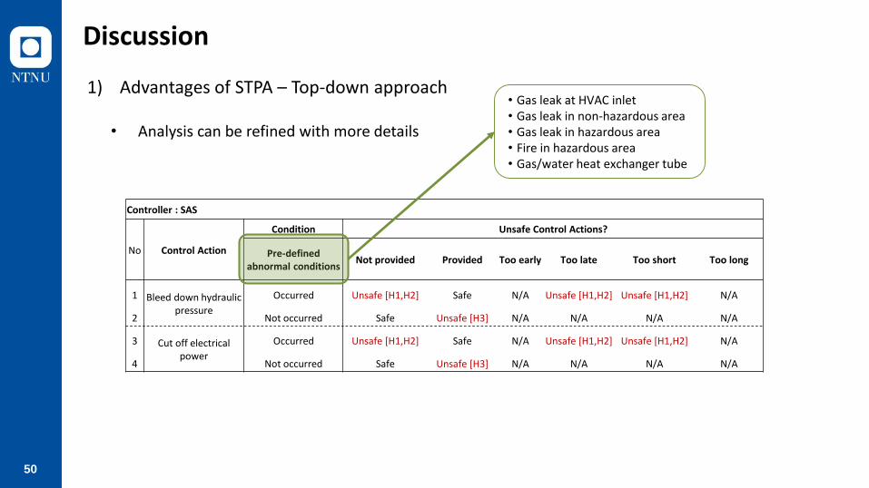
Discussion
1) Advantages of STPA – Top-down approach
• Analysis can be refined with more details
Controller : SAS
No Control Action
Condition Unsafe Control Actions?
Pre-defined abnormal conditions
Not provided Provided Too early Too late Too short Too long
1 Bleed down hydraulic pressure
Occurred Unsafe [H1,H2] Safe N/A Unsafe [H1,H2] Unsafe [H1,H2] N/A
2 Not occurred Safe Unsafe [H3] N/A N/A N/A N/A
3 Cut off electrical power
Occurred Unsafe [H1,H2] Safe N/A Unsafe [H1,H2] Unsafe [H1,H2] N/A
4 Not occurred Safe Unsafe [H3] N/A N/A N/A N/A
• Gas leak at HVAC inlet• Gas leak in non-hazardous area• Gas leak in hazardous area• Fire in hazardous area• Gas/water heat exchanger tube

51
Discussion
Gas at HVAC
inlet
GAS in non-
hazardous area
Gas in
hazardous area
Fire in
hazardous area
Gas/water
heat exchanger Not provided Provided Too early Too late Too short Too long
1 Not detected Not detected Not detected Not detected Normal
2 Detected Not detected Not detected Not detected Normal
3 Not detected Detected Not detected Not detected Normal
4 Not detected Not detected Detected Not detected Normal
5 Not detected Not detected Not detected Detected Normal
6 Not detected Not detected Not detected Not detected Ruptured
7 Detected Detected Not detected Not detected Normal
8 Detected Not detected Detected Not detected Normal
9 Detected Not detected Not detected Detected Normal
10 Detected Not detected Not detected Not detected Ruptured
11 Not detected Detected Detected Not detected Normal
12 Not detected Detected Not detected Detected Normal
13 Not detected Detected Not detected Not detected Ruptured
14 Not detected Not detected Detected Detected Normal
15 Not detected Not detected Detected Not detected Ruptured
16 Not detected Not detected Not detected Detected Ruptured
17 Detected Detected Detected Not detected Normal
18 Detected Detected Not detected Detected Normal
19 Detected Detected Not detected Not detected Ruptured
20 Detected Not detected Detected Detected Normal
21 Detected Not detected Detected Not detected Ruptured
22 Detected Not detected Not detected Detected Ruptured
23 Not detected Detected Detected Detected Normal
24 Not detected Detected Detected Not detected Ruptured
25 Not detected Detected Not detected Detected Ruptured
26 Not detected Not detected Detected Detected Ruptured
27 Detected Detected Detected Detected Normal
28 Detected Detected Detected Not detected Ruptured
29 Detected Detected Not detected Detected Ruptured
30 Detected Not detected Detected Detected Ruptured
31 Not detected Detected Detected Detected Ruptured
32 Detected Detected Detected Detected Ruptured
Controller : SAS
No Control Action
Unsafe Control Actions?
Bleed down hydraulic
pressure
Cut off electrical power
Condition
52
Discussion
1) Advantages of STPA – Top-down approach
• Analysis can be refined with more details

53
Discussion
2) Suggestions – Modelling of fail-safe functions
54
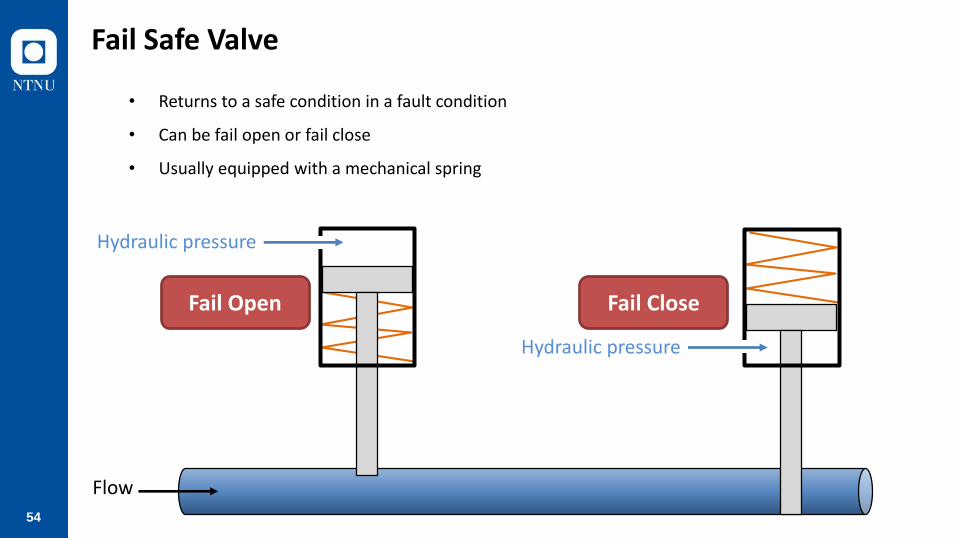
Fail Safe Valve
• Returns to a safe condition in a fault condition
• Can be fail open or fail close
• Usually equipped with a mechanical spring
Hydraulic pressure
Flow
Hydraulic pressure
Fail Open Fail Close
55
Discussion
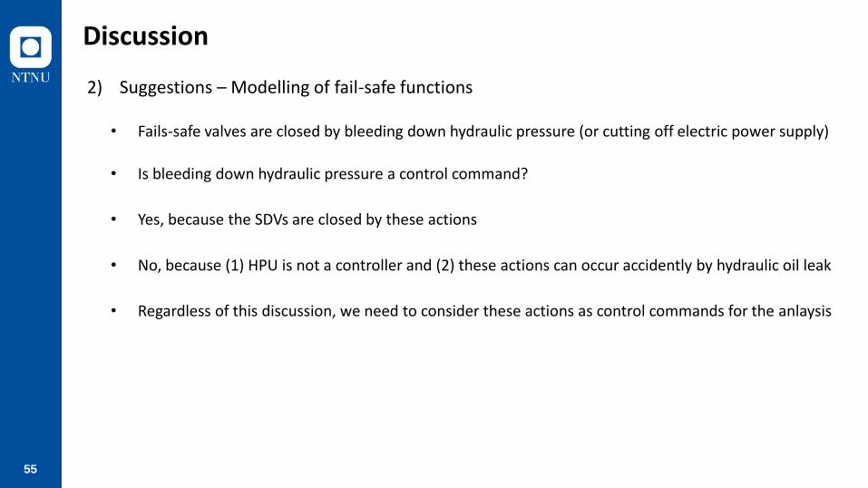
2) Suggestions – Modelling of fail-safe functions
• Fails-safe valves are closed by bleeding down hydraulic pressure (or cutting off electric power supply)
• Is bleeding down hydraulic pressure a control command?
• Yes, because the SDVs are closed by these actions
• No, because (1) HPU is not a controller and (2) these actions can occur accidently by hydraulic oil leak
• Regardless of this discussion, we need to consider these actions as control commands for the anlaysis

56
Discussion
2) Suggestions – Modelling of fail-safe functions
Human Operator
Control/Power System Other Sensors
• Status of other subseaand topsidesystems
ESD Valves
• Status of ESD valves
• Hydraulic pressure
• Status of other subseaand topside systems
• Status of ESD valves
• Emergencyshutdown
• Status of other topside systems
• Status of othersubsea systems
• Status of ESD valves
Control/Power System
• Bleed down hydraulic pressure
• Cut off elec. power
ESDValves
• Pressure of DHSV• Pressure of PMV• Pressure of PWV• Pressure of CIV
Human Operator
Other Topside Sensors
• Status of other subsea systems Other Subsea
Sensors
HPU
SCM
Hydraulic pressure Electric power
Dump DCV
DHSV DCV
PMV DCV
PWV DCV
CIV DCV
DHSV PMV PWV CIV Sensors
Hydraulicpressure
Hydraulicpressure
Hydraulicpressure
Hydraulicpressure
• Status of other subseaand topside systems
• Status of ESD valves
SEM
• Bleed down hyd. pressure
• Cut off electricalpower
SASESD
EPU
• Emergencyshutdown

57
Discussion
2) Suggestions – Long distance between controller and actuator

58
Discussion
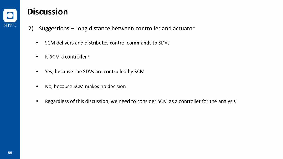
2) Suggestions – Long distance between controller and actuator
59
Discussion
2) Suggestions – Long distance between controller and actuator
• SCM delivers and distributes control commands to SDVs
• Is SCM a controller?
• Yes, because the SDVs are controlled by SCM
• No, because SCM makes no decision
• Regardless of this discussion, we need to consider SCM as a controller for the analysis

60
Discussion
Human Operator
Control/Power System Other Sensors
• Status of other subseaand topsidesystems
ESD Valves
• Status of ESD valves
• Hydraulic pressure
• Status of other subseaand topside systems
• Status of ESD valves
• Emergencyshutdown
• Status of other topside systems
• Status of othersubsea systems
• Status of ESD valves
Control/Power System
• Bleed down hydraulic pressure
• Cut off elec. power
ESDValves
• Pressure of DHSV• Pressure of PMV• Pressure of PWV• Pressure of CIV
Human Operator
Other Topside Sensors
• Status of other subsea systems Other Subsea
Sensors
HPU
SCM
Hydraulic pressure Electric power
Dump DCV
DHSV DCV
PMV DCV
PWV DCV
CIV DCV
DHSV PMV PWV CIV Sensors
Hydraulicpressure
Hydraulicpressure
Hydraulicpressure
Hydraulicpressure
• Status of other subseaand topside systems
• Status of ESD valves
SEM
• Bleed down hyd. pressure
• Cut off electricalpower
SASESD
EPU
• Emergencyshutdown
2) Suggestions – Long distance between controller and actuator

61
Discussion
3) Remaining Challenges
• Status of other topside systems
• Status of othersubsea systems
• Status of ESD valves
Control/Power System
• Bleed down hydraulic pressure
• Cut off elec. power
ESDValves
• Pressure of DHSV• Pressure of PMV• Pressure of PWV• Pressure of CIV
Human Operator
Other Topside Sensors
• Status of other subsea systems Other Subsea
Sensors
HPU
SCM
Hydraulic pressure Electric power
Dump DCV
DHSV DCV
PMV DCV
PWV DCV
CIV DCV
DHSV PMV PWV CIV Sensors
Hydraulicpressure
Hydraulicpressure
Hydraulicpressure
Hydraulicpressure
• Status of other subseaand topside systems
• Status of ESD valves
SEM
• Bleed down hyd. pressure
• Cut off electricalpower
SASESD
EPU
• Emergencyshutdown
• Dynamic control structure

62
Discussion
3) Remaining Challenges
• When to stop the analysis?
UCA.SAS.001: SAS does not provide bleed down hydraulic pressure command when pre-defined abnormal conditions have occurred
ScenarioAssociated Causal Factors
Safety Constraints
SNR.SAS.001.02SAS receives no information about pre-defined conditions
Failure of sensors SC.SAS.001.02.01All sensors for pre-defined conditions must be tested periodicallySC.SAS.001.02.02All sensors for pre-defined conditions must have redundancy (e.g., 2oo3 configuration)
No power supply to sensors
SC.SAS.001.02.05All sensors for pre-defined conditions must be connected to redundant power supply or UPSSC.SAS.001.02.04SAS must generate an alarm when no signal is received from any sensors for pre-defined conditions

63
Conclusion and Future Work

64
Conclusion
• Advantages of STPA - systematic approach to identify hazards
- wide scope
- top-down approach
• Challenges of STPA - Quantification of the results
- STPA Step 2 relies on brainstorming
- Dynamic control structure

65
Future Work
• Subsea Processing System
• Subsea Safety System
• Subsea Production System
• Summarize overall challenges and provide solutions

66
Any Questions?

67


