NASA TECHNICAL MEMORANDUM N 69 10110 NASA TM X-53769 August 21, 1968 APPLICATION OF THE CHARACTERISTIC METHOD IN CALCULATING THE TIME DEPENDENT, ONE-D IMENS IONAL, COMPRESS I BLE FLOW IN A TUBE WIND TUNNEL Aero-Astrodynamics Laboratory NASA https://ntrs.nasa.gov/search.jsp?R=19690000779 2020-05-25T19:21:41+00:00Z
Transcript
N A S A TECHNICAL MEMORANDUM
N 6 9 1 0 1 1 0 NASA TM X-53769
August 21, 1968
APPLICATION OF THE CHARACTERISTIC METHOD I N CALCULATING THE TIME DEPENDENT, ONE-D IMENS IONAL, COMPRESS I BLE FLOW I N A TUBE WIND TUNNEL
APPLICATION OF THE CHARACTERISTIC METHOD I N CALCULATING THE
TIME DEPENDENT, ONE-DIMENSIONAL, COMPRESSIBLE FLOW
I N A TUBE WIND TUNNEL
John D. Warmbrod and Heinz G. S t ruck
George C . Marshall Space F l i g h t Center
ABSTRACT
This r e p o r t p re sen t s i n d e t a i l a c a l c u l a t i o n method f o r one- dimensional, time-dependent flow through a pressure- tube wind tunne l . The computational procedure involves the method of c h a r a c t e r i s t i c s f o r t h e one-dimensional unsteady flow of a p e r f e c t gas and accounts f o r area changes, shock formations, and i n t e r s e c t i o n of d i s c o n t i n u i t i e s i n the flow f i e l d .
A computer program w r i t t e n i n F o r t r a n language w a s cons t ruc t ed f o r t h e CDC 3200 d i g i t a l computer and is presented along w i t h a d e t a i l e d d e s c r i p t i o n of the p r e p a r a t i o n of i npu t f o r the program.
Calculated r e s u l t s of t he program are presented f o r a pressure- tube wind tunnel now under cons t ruc t ion a t MSFC.
NASA - GEORGE C . MARSHALL SPACE FLIGHT CENTER
.
NASA - GEORGE C. MARSHALL SPACE FLIGHT CENTER
-
Technical M e m o r a n d u m X-53769
A u g u s t 21, 1968
APPLICATION OF THE CHARACTERISTIC METHOD I N CALCULATING THE
TIME DEPENDENT, ONE-DIMENSIONAL, COMPRESSIBLE FLOW
I N A TUBE WIND TUNNEL
John D. W a r m b r o d and H e i n z G. S t r u c k
4
AEROPHYSICS D I V I S I O N AERO-ASTRODYNAMICS LABORATORY
RESEARCH AND DEVELOPMENT OPERATIONS
TABLE OF CONTENTS
Page
I . INTRODUCTION ............................................ I1 . THE DIFFERENTIAL EQUATIONS .............................. 111 . THE NORMAL SHOCK RELATIONS .............................. I V . THE INITIAL CONDITIONS .................................. V . CHARACTERISTIC SOLUTION .................................
A . C a l c u l a t i o n Procedure f o r a Regular Po in t ........... B . C a l c u l a t i o n Procedure f o r Po in t s Near Boundaries ....
V I . CALCULATION PROCEDURE FOR A CONTACT SURFACE ............. V I 1 . CALCULATION PROCEDURE FOR A SHOCK POINT .................
A . Q Shock P o i n t ....................................... B . P Shock P o i n t .......................................
V I 1 1 . INTERACTION OF DISCONTINUITIES .......................... A . Merging of Two Q Shocks ............................. B . Cross ing of a Q Shock by a Contac t Su r face ..........
IX . EXIT CONDITIONS ......................................... A . Subsonic Flow a t E x i t ............................... B . Sonic Flow a t E x i t .................................. C . Supersonic Flow a t Ex i t .............................
X . SOME PERTINENT DETAILS ABOUT THE CALCULATION PROCEDURE .. A . Geometrical Aspects ................................. B . Grid Cont ro l ........................................ C . Restart Procedure ...................................
X I . DISCUSSION OF THE RESULTS. .............................. APPENDIX A . D e r i v a t i o n of t h e C h a r a c t e r i s t i c Equat ions ........
............ APPENDIX B . The F o r t r a n Program and Its I n p u t Data 1 . P r e p a r a t i o n of the Inpu t Data f o r the
2 . Computer Program .............................. The F o r t r a n Program and Subrout ines ...........
1
3
7
11
14 15 18
21
25 25 27
29 30 32
34 35 36 36
36 36 37 38
38
55
59
59 61
iii
LIST OF ILLUSTRATIONS
T i t l e Figure
1 A
1 B
9
10
11
Aerodynamic Boundaries of F a c i l i t y wi th the Mach 2 Nozzle. ...................................... 42
Aerodynamic Boundaries of F a c i l i t y w i t h the Mach 1 Nozzle ....................................... 43
44
45
........................ Wave Diagram f o r MTEST - - 2.0
- Wave Diagram f o r MTEST - 1 . 4 ........................ Wave Diagram f o r MTEST = 1 . 7 ........................ 46
47 ........................ Wave Diagram f o r MTEST = 3.5
........................ Wave Diagram f o r = 5.0 48
Pressure as a Function of Time a t a S t a t i o n i n the Test Sec t ion f o r Supersonic T e s t Mach Numbers.. ..... 49
Pressure as a Function of Time a t a S t a t i o n i n the Test Sec t ion f o r Subsonic and Sonic Test Mach Numbers...... ....................................... 50
S t a r t Time as a Function of T e s t Mach Number.. ...... 51
T e s t Reynolds Number as a Function of Test Mach Number........ ...................................... 52
S t a t i c Pressure as a Function of Mach Number i n the Test Sec t ion During Steady Flow Period .......... 53
i v
Symbol
a
A
cP
f
LO
MS
M~~~~
P
P C
P
U
S W
Y
P
DEFINITION OF SYMBOLS
D e f i n i t i o n
nondimensional speed of sound a"/a;
c ros s - s e c t i o n a l a r e a
s p e c i f i c h e a t a t constant p r e s s u r e
f9CLo nondimensional quan t i ty - where f" is the sum of body
and d i s s i p a t i v e forces p e r u n i t mass
2 a;
t o t a l l e n g t h of f a c i l i t y (wi th dimensions)
Mach number o f shock
Mach number i n t e s t s e c t i o n du r ing s t e a d y s t a t e d u r a t i o n
nondimensional s t a t i c p r e s s u r e p"/p:
i n i t i a l p re s su re r a t i o a c r o s s diaphragm
r i g h t running c h a r a c t e r i s t i c v a r i a b l e
l e f t running c h a r a c t e r i s t i c v a r i a b l e
gas cons t an t
nondimensional s p e c i f i c entropy s / c (y -1 )
nondimens i o n a l time a:t"'/Lo
nondimens i o n a l temperature T"/ TE
nondimensional f low v e l o c i t y u"/a:
nondimensional shock v e l o c i t y w;/a:
P
r a t i o of s p e c i f i c heats
nondimens iona l dens i ty
ao +;k 0
nond imens i o n a l quan t i ty where fl r e p r e s e n t s the yA pz
Subsc r ip t s
DEFINITION OF SYMBOLS (Continued)
D e f i n i t i o n
0 reference condi t ions which f o r t h e case a t hand were the condi t ions on the r i g h t s i d e of the diaphragm b e f o r e r u p t u r e
S shock condi t ions
C.S. contact s u r f a c e condi t ions
S u p e r s c r i p t s
9; d h e n s iona l q u a n t i t i e s
v i
TECHNICAL MEMORANDUM X-53769
APPLICATION OF THE CHARACTERISTIC METHOD I N CALCULATING THE
TIME DEPENDENT, ONE-DIMENSIONAL, COMPRESSIBLE FLOW
I N A TUBE WIND TUNNEL
SUMMARY
This r e p o r t p re sen t s i n d e t a i l a c a l c u l a t i o n method f o r one-dimen- s i o n a l , time-dependent flow through a pressure- tube wind tunnel . The - computational procedure involves the method of c h a r a c t e r i s t i c s for the one-dimensional unsteady flow of a p e r f e c t gas and accounts f o r a r e a changes, shock formations, and i n t e r s e c t i o n of d i s c o n t i n u i t i e s i n the flow f i e l d .
A computer program w r i t t e n i n For t r an language was constructed f o r t h e CDC 3200 d i g i t a l computer and i s presented along w i t h a d e t a i l e d d e s c r i p t i o n of the p r e p a r a t i o n of input f o r the program.
Calculated r e s u l t s of the program a r e presented f o r a pressure- tube wind tunne l now under c o n s t r u c t i o n a t MSFC.
I. INTRODUCTION
Ludwieg [ 7 ] f i r s t proposed the p r i n c i p l e of the p r e s s u r e tube wind tunne l and supervised the cons t ruc t ion of the f i r s t f a c i l i t y of t h i s type a t t h e Aerodynamische Versuchsanstal t i n Gzt t ingen. Some experiments were r epor t ed i n r e fe rence 8 of the s t a g n a t i o n p res su re l o s s , and some s c h l i e r e n p i c t u r e s were made of the supe r son ic j e t a t t he o u t l e t of the nozzle . Ca lcu la t ions and measurements were given t h a t show the e x t e n t of s t a g n a t i o n p res su re l o s s e s i n the t e s t s e c t i o n w i t h inc reas ing bound- a r y l a y e r t h i ckness . It was concluded t h a t f o r l a r g e tube diameters (and t h e r e f o r e l a r g e Reynolds numbers) t he l i m i t l e n g t h ( s t a g n a t i o n p r e s s u r e l o s s l e s s than 1 pe rcen t due t o the boundary l a y e r ) of tne tube is approximately 100 tube diameters.
A supe r son ic p re s su re tube wind tunnel w a s cons t ruc t ed a t the Royal Armament Research and Development Establishment i n England during 1957, and some measurements from t h i s w i n d tunnel a r e r epor t ed i n r e f e r e n c e 4 . Reference 3 r epor t ed f u r t h e r measurements of the pressure at the nozzle end of the tube and s t a t i c and p i t o t p re s su res i n the working s e c t i o n of t he nozzle . The diaphragm was located a t the nozzle e x i t . P i c t u r e s of
L
the flow around a model were made by a h igh speed camera. c a l c u l a t i o n procedure f o r one-dimensional flow repor t ed i n r e f e r e n c e 3 w a s used to o b t a i n a n a l y t i c a l r e s u l t s f o r running times and s t a t i c p re s - s u r e s i n the t e s t s e c t i o n . Their a n a l y t i c a l procedure assumed t h a t the expansion fan emanated from the nozzle t h r o a t r a t h e r than from the diaphragm l o c a t i o n , and thus neglected the unsteady expansion from the diaphragm through the nozzle t h r o a t . changes were accounted f o r by s t eady s t a t e assumptions. An approximate method f o r c a l c u l a t i n g the boundary l a y e r growth along the tube i s a l s o presented.
An approximate
The e f f e c t s of c r o s s - s e c t i o n a l a r e a
Reference 6 , which is a good d i s c u s s i o n on the s o l u t i o n of hyperbol ic d i f f e r e n t i a l equat ions that d e s c r i b e one-dimensional , non-steady, com- p r e s s i a e , m u l t i - i s e n t r o p i c flow, presented t h r e e methods f o r so lv ing the d i f f e r e p t i a l equa t ions , along wi th the advantages and disadvantages assoc- i a t e d with each method. Some hand c a l c u l a t i o n s f o r a n example of i s en - t r o p i c flow were made, b u t no ex tens ive a p p l i c a t i o n of the procedures was performed.
B u l l [ l , 21 g ives some measurements and c a l c u l a t i o n s of t he s t a r t i n g processes on a n i n t e r m i t t e n t supersonic wind tunnel t h a t were made a t the I n s t i t u t e of Aerophysics a t the U n i v e r s i t y of Toronto. This tunnel con- s i s ted of a vacuum r e s e r v o i r a t the end of a Lava1 nozzle wi th a c e l l o - phane diaphragm loca ted e i t h e r upstream o r downstream of the t h r o a t . Some c a l c u l a t i o n s were made f o r one case assuming the flow t o be time- dependent and one-dimensional, and a wave diagram w a s presented f o r t h e e a r l y phase of t h e flow from these c a l c u l a t i o n s .
Rudinger [ 9 ] presen t s an e x c e l l e n t t e x t on c a l c u l a t i o n procedures f o r solving t h e p a r t i a l d i f f e r e n t i a l . equat ions of non-steady, one-dimen- s i o n a l flow of compressible f l u i d s through a duc t . Because of the con- s i s t e n t a n d s t r a i g h t f o r w a r d p r e s e n t a t i o n of the s o l u t i o n techniques descr ibed i n t h i s book, many of the c a l c u l a t i o n procedures descr ibed i n the present r e p o r t were borrowed from t h i s sou rce .
D a b [5] discussed a proposed Ludwieg-tube type of f a c i l i t y a t t h e Marshall Space F l i g h t Center f o r aerodynamic t e s t i n g , a t o r near f u l l s c a l e Reynolds number, of a Sa tu rn V r o c k e t . This proposal generated an i n t e r e s t a t the Center i n developing a n a n a l y t i c a l c a p a b i l i t y f o r c a l c u l a t i n g s t a r t times and o t h e r p r o p e r t i e s of t he flow p e r t i n e n t t o t h i s f a c i l i t y , thus leading t o the m a t e r i a l presented he re . Some experi- mental r e s u l t s of the s t a r t i n g c h a r a c t e r i s t i c s f o r a sma l l - sca l e p i l o t model of a blowdown wind tunnel t h a t w a s t e s t e d a t MSFC a r e presented i n r e fe rence 11.
2
This paper p re sen t s a numerical procedure f o r so lv ing the pa r t i a l d i f f e r e n t i a l equat ions t h a t descr ibe the flow i n a pressure- tube wind tunnel by a method g e n e r a l l y r e f e r r e d t o as the "method of c h a r a c t e r - i s t i c s . " The mathematical model o f the flow is assumed t o be time- dependen t , one-d imens ional , mu1 ti- i s e n t r o p i c , and compress i b l e. A computer program i n F o r t r a n I V language was formulated, and wave d i a - grams and o t h e r r e s u l t s of the flow t h a t were c a l c u l a t e d from t h i s program a r e given.
The tunnel considered h e r e (see Figure 1 ) c o n s i s t s of a long tube t h a t s e r v e s as the s t o r a g e r e s e r v o i r , a convergent-divergent nozzle and t e s t s e c t i o n , and an o u t l e t i n t o e i t h e r the atmosphere o r an emptying r e s e r v o i r . The tube, closed a t one end, i s divided downstream of the t e s t s e c t i o n by a diaphragm. When the diaphragm i s rup tu red , the h igh p r e s s u r e gas on the l e f t s i d e of the diaphragm expands and compresses the gas on t h e 1ow.pressure s i d e , thus c r e a t i n g a shock wave, con tac t s u r f a c e , and an expansion f a n (see Sec t ion I V ) . The con tac t s u r f a c e i s def ined as the gas p a r t i c l e s that were i n i t i a l l y i n c o n t a c t w i t h the diaphragm s u r f a c e . The expansion fan , bounded on t h e l e f t by what i s termed he re as the head wave and on t h e r i g h t by the t a i l wave, i s mathematically the family of l e f t - runn ing c h a r a c t e r i s t i c s . The s o l u - t i o n c o n s i s t s of t r a c i n g the l e f t - and r igh t - runn ing c h a r a c t e r i s t i c curves i n the ( x , t ) - p l a n e a f t e r the flow s t a r t s a t time = 0.
The s t a r t i n g time is de f ined as the t i m e when the flow p r o p e r t i e s i n t h e t e s t s e c t i o n become constant . The end t e s t time is def ined as the time t h a t i t takes the headwave t o t r a v e l along the tube, r e f l e c t from the closed end of the tube, and reach the t e s t s e c t i o n . Thus, t he use- f u l r u n time i s the d i f f e r e n c e between the end t e s t t i m e and the s t a r t time. It i s f a i r l y ev iden t t h a t run times can be increased by inc reas - ing the l eng th of t he tube. Ludwieg [8] pointed ou t t h a t t o keep boundary l a y e r e f f e c t s n e g l i g i b l e the tube l e n g t h should no t exceed approximately 100 tube diameters . Boundary l a y e r e f f e c t s can be approximately accounted f o r i n the method presented i n t h i s r e p o r t .
11. THE DIFFERENTIAL EQUATIONS
The main purpose of t h i s r e p o r t is t o p re sen t t he p r a c t i c a l numeri- c a l procedures f o r so lv ing the time-dependent equat ions f o r one-dimen- s i o n a l flow through a wind tunnel . Therefore , the fundamental d i f f e r e n t i a l equat ions which a r e der ived i n numerous r e f e r e n c e s w i l l be l i s t e d he re only i n the f i n a l form (see reference 9 ) :
3
Continui ty Equation
Momentum Equa t&
Equation of S t a t e
a*2 = 7 = 7RT".
In t eg ra t ed Form of the F i r s t Law of Thermodynamics
( 3 )
The s u b s c r i p t o i n d i c a t e s some s t a t e from which entropy changes a r e measured. The s t a r s u p e r s c r i p t r e f e r s t o dimensional q u a n t i t i e s . For a d e f i n i t i o n of t he symbols, t he r eade r should r e f e r t o the D e f i n i t i o n of Symbols. The underlying assumptions i n the d e r i v a t i o n of t he above equat ions are :
(1) A l l q u a n t i t i p s depend on the time t" and a s i n g l e coord ina te x" .
(2) There is only one v e l o c i t y component u" and t h a t is i n the 2 ' -direct ion.
(3) The gas fol lows the i d e a l gas l a w s , and the va lues of t he s p e c i f i c h e a t a r e cons t an t . ,
( 4 ) A l l body and d i s s i p a t i v e f o r c e s a r e lumped i n t o a r e s u l t a n t f o r c e pe r u n i t mass, which i s denoted i n t h e momentum equat ion by f*.
( 5 ) G a s i s permit ted t o leave the d u c t through the walls and is denoted i n the c o n t i n u i t y equa t ion by $*, which is def ined as the mass flow through t h e walls per u n i t l eng th .
4
It i s customary t o s o l v e the above s e t of equat ions by a numerical
These curves a r e usual ly def ined as p a r t i c l e paths and i n t e g r a t i o n procedure along a s e t of curves C i n t he independent v a r i a b l e ( x , t ) - p l a n e . c h a r a c t e r i s t i c curves. Appendix A p r e s e n t s t he d e r i v a t i o n of the charac- t e r i s t i c equat ions which a r e presented he re i n t h e i r f i n a l forms.
DS - - - a l n A - a ' I n A + a - + ( y - 1) a - - f ax a t 6 t D t a u 6- Q -
6 s
a t
The entropy cond i t ion ,which must be p re sc r ibed f o r any problem i s given i n a gene ra l form as
and t h i s completes the system of equations f o r the t h r e e dependent v a r i a b l e s a , u , and S. The prescr ibed entropy cond i t ion f o r t he c a l - c u l a t i o n procedures descr ibed i n the subsequent s e c t i o n s of t h i s r e p o r t i s given by
which c h a r a c t e r i z e s the flow as m u l t i - i s e n t r o p i c . This s a t i s f i e s t he cond i t ion t h a t the entropy of each gas p a r t i c l e remains cons t an t ; how- ever, d i f f e r e n t p a r t i c l e s may have d i f f e r e n t e n t r o p i e s .
The s p e c i a l symbols f o r t he d i f f e r e n t i a l ope ra to r s a r e def ined as
a a 8+ - a t + (U + a) - ax - -
5
a 6 = - a - at + (U - a) ax a + u - a=- D a
D t a t ax -
( 9 )
A l l q u a n t i t i e s a r e nondimensional i n the above equat ions (see D e f i n i t i o n of Symbols). Equations (5) through (7) form a system of t h r e e l i n e a r f i r s t - o r d e r equat ions f o r t h r e e dependent v a r i a b l e s , a , u , and S, that w i l l be solved by means of a s tep-by-step procedure. Q , and S vary along curves i n the ( x , t ) - p l a n e t h a t s a t i s f y
The parameters P,
f o r P, (11) dx - = u + a d t
dx d t - = u f o r S.
The c h a r a c t e r i s t i c v a r i a b l e s a r e def ined by t h e r e l a t i o n s
2 p = - y , l a + u
and
2 Q = - a - u . Y - 1
The d e t a i l s of the c a l c u l a t i o n procedure f o r s o l v i n g numerical ly
The e f f e c t s of boundary l a y e r and mass flow through the the system of equations (5) through ( 7 ) a r e given i n l a t e r s e c t i o n s of t h i s r e p o r t . w a l l s of the d u c t were no t considered,and the terms t h a t r e p r e s e n t those e f f e c t s have been omitted from the equa t ions . .
6
111. THE NORMAL SHOCK RELATIONS
The c h a r a c t e r i s t i c equat ions which were der ived from the b a s i c d i f - f e r e n t i a l equat ions i n Appendix A a r e solved by tak ing small s tep-by-s tep increments i n t ime, and t h e so lu t ion f o r each c h a r a c t e r i s t i c proceeds a long i t s r e s p e c t i v e c h a r a c t e r i s t i c . These t h r e e c h a r a c t e r i s t i c curves were r e f e r r e d t o as P i n d i r e c t i o n u + a , Q i n d i r e c t i o n u - a , and S i n d i r e c t t o n u. S ince t h e c h a r a c t e r i s t i c S fol lows a curve of d i r e c - t i o n u, which i s the p a r t i c l e pa th , two curves of t h i s family can never c r o s s . Whenever two curves of the same family ( e i t h e r P o r Q ) meet, a d i s c o n t i n u i t y i n the p re s su re e x i s t s a t t h i s po in t . A boundary i n t h e f low is thus e s t a b l i s h e d , and t h i s boundary i s def ined as a normal shock wave. Two types of shock waves can t h e r e f o r e occur , e i t h e r a P shock (converging of t he P c h a r a c t e r i s t i c s ) o r a Q shock (converging of t he Q c h a r a c t e r i s t i c s ) . The shock wave path w i l l d i v i d e t h e wave diagram i n t o two p a r t s , and on each s i d e c e r t a i n cond i t ions must be matched. S ince i t is assumed t h a t changes of t he f l o w v a r i a b l e s a c r o s s a shock wave t ake p l ace in s t an taneous ly , the s teady s t a t e r e l a t i o n s h i p s between flow v a r i a b l e s on each s i d e of t h e shock can be employed. The equat ions which r e l a t e the flow v a r i a b l e s upstream and downstream of a s t a t i o n a r y normal shock are g e n e r a l l y r e f e r r e d t o as t h e Rankine-Hugoniot equat ions . The d e r i v a t i o n of t hese equat ions can be found i n many r e fe rences ( e . g . , [12, 1 3 ] ) , and t h e r e f o r e w i l l n o t be repea ted here . Since we a r e deal- ing w i t h shocks that move wi th r e spec t t o the coord ina te system, some mod i f i ca t ions t o the s t a t i o n a r y shock r e l a t i o n s a r e necessary . The equat ions appearing i n t h i s s ec t ion are presented i n t h e i r f i n a l form as they were used i n the computational scheme. is def ined he re as the Mach number of a supersonic f low i n which the shock would be s t a t i o n a r y .
The shock Mach number MS
The r e l a t i o n s a c r o s s a Q shock p o i n t a r e as fol lows:
I
7
(3) Q Charac te r i s t i c
UR - 'L a L L a
(4) P C h a r a c t e r i s t i c
u - u R L
L a L a
(5) Entropy
( 6 ) Pressu re
- - - p R - 2Y M 2 - y - 1 PL y + l s y + l '
(7) Shock Veloci ty R e l a t i v e t o the Duct
ws = uL - aL MS. (22)
The s u b s c r i p t s L and R r e f e r t o the flow p r o p e r t i e s on the l e f t - and right-hand s i d e s of the shock p o i n t , and the s u b s c r i p t S r e f e r s t o the shock. Analogous r e l a t i o n s f o r a P shock p o i n t a r e :
8
Ve 1 oc it y
8
c
.
Speed of Sound
(3) Q Characteristic
u - u R L
R a R a
( 4 ) P Characteristic
(5) Entropy
(6) Pressure
- - pL - - 2Y M2 - y-l y + l s y + l ' p R
(7) Shock Velocity Relative to the Duct
w = u + aR MS. S R
The c a l c u l a t i o n procedure a t a shock p o i n t involves the matching of t he c h a r a c t e r i s t i c s o l u t i o n wi th t h e Rankine-Hugoniot s o l u t i o n a t t h e shock p o i n t . From equat ions (18) and (26) , i t can be seen that the r e l a t i o n s
= a s shock
where f o r t he Rankine-Hugoniot s o l u t i o n ,
expressing equat ion
.
and, from t h e c h a r a c t e r i s t i c s o l u t i o n , is c a l c u l a t e d from equa- t i o n (30) f o r t he a p p r o p r i a t e shock. The s u b s c r i p t s R.H. and CH. r e f e r t o the Rankine-Hugoniot and c h a r a c t e r i s t i c s o l u t i o n s , r e s p e c t i v e l y . The condi t ion t h a t A - a t a shock p o i n t is s a t i s f i e d by ~ R . H . - 'SCH.
(31) as
which, with 4 and y g iven , is a n a l g e b r a i c equa t ion f o r MS. This
equa t ion is solved i n t h e computer program by the Newton-Raphson method f o r f inding the r e a l r o o t s of a l g e b r a i c and t r anscenden ta l equat ions. The i t e r a t i o n procedure t o s a t i s f y matching t h e s o l u t i o n of t he charac- t e r i s t i c equations w i t h t h e Rankine-Hugoniot equat ions a t a shock p o i n t is described i n Sec t ion V I I .
CH.
Some remarks should be made he re about how the presence of a shock wave (P o r Q ) a f f e c t s t he flow and p o s s i b l y the o rde r of c a l c u l a t i o n as pe r t a in ing t o t h e wave diagram. Assuming t h e gas t o be flowing from l e f t t o r i g h t , the v e l o c i t y of a P shock is supe r son ic r e l a t i v e t o the v e l o c i t y of the gas flow t o the r i g h t ; t h e r e f o r e , t he P shock overtakes t h e flow of gas ahead of it. The flow cond i t ions which l i e t o the r i g h t of the P shock p a t h i n the wave diagram are no t then inf luenced by e i t h e r t he presence o r s t r e n g t h of t he P shock wave. The speed of a gas which is flowing from l e f t t o r i g h t w i l l then be increased a f t e r passage of t he P shock wave.
1 0
For a Q shock, t he v e l o c i t y of t he flow is g r e a t e r than the veloc- i t y of t h e shock r e l a t i v e t o the d u c t , and t h e r e f o r e the flow cond i t ions which l i e t o t h e l e f t of t he Q shock p a t h i n the wave diagram a r e inde- pendent of t he s t r e n g t h o r presence of the shock wave. It is seen , then, t h a t , i n case of a gas flowing from l e f t t o r i g h t , a Q shock w i l l slow down t h e flow as i t passes through the shock.
IV. THE INITIAL CONDITIONS
Consider a duct which i s closed on the l e f t end and which opens i n t o t h e atmosphere o r i n t o a n emptying r e s e r v o i r on the r i g h t end divided by a diaphragm i n t o two chambers. Let t he p re s su re of the gas on the l e f t - hand s i d e of t h e diaphragm be higher than on the r i g h t , and fur thermore, i t i s n o t r e s t r i c t e d t h a t t he gases on both s i d e s of t he diaphragm be the same o r have t h e same temperature. When the diaphragm is suddenly removed, t he gas which was i n i t i a l l y on t h e l e f t s i d e of the diaphragm expands and compresses the gas which w a s i n i t i a l l y on the r ight-hand s i d e , forming a P shock. The P shock t r ave l s through the gas which was i n i t i a l l y on t h e r ight-hand s i d e . Also created a t diaphragm rup tu re i s a con tac t s u r f a c e . This con tac t s u r f a c e i s defined as the i n t e r f a c e between the paths of t h e gas p a r t i c l e s which were i n i t i a l l y i n con tac t w i th each s i d e of t h e diaphragm. t h e r e f o r e cons is ts of the simultaneous s o l u t i o n of t he c h a r a c t e r i s t i c equat ions , the Rankine-Hugoniot equations , and the boundary cond i t ions f o r t he con tac t s u r f a c e . It i s assumed t h a t t he diaphragm is i n s t a n t l y removed, s o the d i scuss ion t h a t follows a p p l i e s f o r time equals zero a t the diaphragm l o c a t i o n xD.
The problem a t the i n s t a n t the diaphragm is rup tu red
t Consider the duct shown i n the i l l u s t r a t i o n which is divided i n t o two chambers by a diaphragm. Let t he sub- s c r i p t 2 r e f e r t o the h igh p res su re gas on the l e f t -
and the s u b s c r i p t 1 r e f e r t o P Shock hand s i d e of t he diaphragm
the gas on the r ight-hand s i d e . The p resc r ibed i n i t i a l cond i t ions f o r t he gases i n the two chambers a r e the fol lowing:
0 0
11
(1)
(2)
t h e p r e s s u r e of t h e gases on each s i d e p*, and p:,
the r a t i o of s p e c i f i c h e a t of t h e g a s e s y2 and y1 and t h e i r gas c o n s t a n t s R2 and R,,
t h e tempera tures of t h e gases T.k, and T:, and (3)
( 4 ) t h e geometry of t h e duc t i n a form such t h a t t h e term (dA/dx)/A can be c a l c u l a t e d a t any s t a t i o n , x, t h e loca - t i o n of t h e diaphragm, xg, and the t o t a l l e n g t h , Lo.
It i s convenient t o choose t h e i n i t i a l c o n d i t i o n s of t h e gas on t h e r igh t -hand s i d e of t h e diaphragm as the r e f e r e n c e s t a t e . One has then t h e fo l lowing va lues f o r t h e i n i t i a l p r o p e r t i e s of t h e f low on t h e r i g h t - and l e f t -hand s i d e s , r e s p e c t i v e l y .
* a 1 = - = 1
2 0
s, = so = 0
ay 2
Y 2 - P2 = 1 a2 + u 2
2 Y 2 - 1 a2 - u 2 42 =
P;
PJ; P 2 = -
(33)
A l l d i s t a n c e s a r e nondimensionalized by t h e t o t a l l e n g t h of the d u c t , L,, and the t ime i s nondimensionalized by
,
a" t*
LO
0 t = - ( 3 4 )
12
The wave phenomenon that develops a t diaphragm r u p t u r e i s shown i n The d e t a i l s of c a l c u l a t i n g the i n i t i a l s o l u t i o n s are the i l l u s t r a t i o n .
g iven i n the fol lowing s t e p s :
(1) Assume t h a t t h e v e l o c i t y u3 ( the v e l o c i t y between the c o n t a c t s u r f a c e and the P shock) has been g iven as a r e s u l t of t h e pre- v ious i t e r a t i o n cyc le o r f o r t he f i r s t i t e r a t i o n has been guessed. S ince the v e l o c i t y , ul, and speed of sound, al, are known, the P shock Mach number can be c a l c u l a t e d by the q u a d r a t i c s o l u t i o n of equa t ion (23) from the Rankine-Hugoniot r e l a t i o n s :
(2) C a l c u l a t e the flow p r o p e r t i e s on the l e f t s i d e of t h e P shock by the Rankine-Hugoniot r e l a t i o n s :
, (3) One of the boundary condi t ions a c r o s s the c o n t a c t s u r f a c e
i s s a t i s f i e d by s e t t i n g p 4 = p3, and s i n c e t h e expansion takes p l ace i s e n t r o p i c a l l y , t he speed of sound on t h e l e f t s i d e of the c o n t a c t s u r - face is given by
13
( 4 ) The v e l o c i t y u4 on the l e f t s i d e of the c o n t a c t s u r f a c e i s given by the requirement t h a t the c h a r a c t e r i s t i c v a r i a b l e P remains cons t an t from t h e head-wave t o t h e l e f t s i d e of t he c o n t a c t su r f ace :
From the d e f i n i t i o n of P, t he v e l o c i t y u4 can be c a l c u l a t e d by
2 72 - 1 a4.
u4 = P4 -
(5) S a t i s f y t h e second boundary cond i t ion a c r o s s the c o n t a c t s u r f a c e by s e t t i n g u3 = u4 which y i e l d s a r ev i sed va lue f o r u3. S t e p s (1) through (5) a r e repeated u n t i l the d i f f e r e n c e between t h e c a l c u l a t e d va lues i n u3 f o r subsequent i t e r a t i o n cyc le s is less than a p resc r ibed to l e rance .
A t the i n i t i a l t i m e t = 0, a centered expansion f a n o r i g i n a t e s a t the diaphragm l o c a t i o n which is bounded on the l e f t by the head-wave (Q2 c h a r a c t e r i s t i c ) and on the r i g h t by the tail-wave (Q4 c h a r a c t e r i s t i c ) . Addit ional Q waves a r e introduced between the head- and ta i l -waves t o keep the net of c h a r a c t e r i s t i c s s u f f i c i e n t l y f i n e ; e .g . , a t o t a l of n i n i t i a l Q waves i s employed i n the computer program.
V. CHARACTERISTIC SOLUTION
I n the numerical s o l u t i o n of t he s e t of c h a r a c t e r i s t i c equat ions given i n Sect ion 11, s e v e r a l procedures could be employed. l y i n g process f o r so lv ing t h e s e equat ions i s , however, the same rega rd - l e s s of the p a r t i c u l a r procedure and is the i n t e g r a t i o n of t he c h a r a c t e r i s t i c equat ions along t h e i r r e s p e c t i v e paths i n the x, t -plane. This i n t e g r a t i o n is c a r r i e d o u t by a s tep-by-step procedure along s h o r t s t r a i g h t l i n e segments, t he s l o p e s of t h e r e s p e c t i v e c h a r a c t e r i s t i c v a r i a b l e s being approximated by the average of t h e i r va lues a t the end of t he s h o r t l i n e segments. The c h a r a c t e r i s t i c curves f o r t he case a t hand a r e designated as P , whose pa th i n the x , t plane i s i n d i r e c t i o n u + a , Q i n d i r e c t i o n u - a, and S i n d i r e c t i o n u. Af t e r exp lo r ing s e v e r a l d i f f e r e n t procedures , i t w a s decided t o use a cons t an t time i n t e r v a l and t o follow the pa th of one of t he family of c h a r a c t e r i s t i c s ( Q ) , and t o u s e a n i n t e r p o l a t i o n technique t o fo l low the pa th of t he o t h e r family (P) between subsequent t i m e i n t e r v a l s . The o rde r of cal- c u l a t i o n as performed by t h e computer program is from l e f t t o r i g h t a long a l i n e t = cons tan t .
The under-
14
.
A. Ca lcu la t ion Procedure f o r a Regular P o i n t
s o l u t i o n has been completed f o r j p o i n t s on t h e l i n e t l = t o + At
s c r i p t A r e f e r t o p r o p e r t i e s a t tl” the j + 1 p o i n t on the l i n e t l which is t o be c a l c u l a t e d , B r e f e r t o the p o i n t or! t he to l i n e t o r through which t h e P c h a r a c t e r - i s t i c t h a t i n t e r s e c t s p o i n t s A and B passes, C r e f e r t o the p o i n t on t h e to l i n e through
(see i l l u s t r a t i o n ) . Let the sub-
which t h e entropy p a t h that
Entropy Path j A f * &
Q Wave
> X
The s t r a i g h t l i n e segment f o r t he P wave t h a t i n t e r s e c t s p o i n t s A and B i n the t i m e i n t e r v a l t l - to = At m u s t s a t i s f y the r e l a t i o n
B x - x (u + a)A + (u + a) A B - -
At 2 9 (42 )
which can be r e w r i t t e n as
( 4 3 ) At
A B 2 B’ ( u + a ) = x + - ( u + a ) At A 2 x - -
The l e f t s i d e of the above equation r e l a t e s t he p o s i t i o n and flow pro- p e r t i e s uA and aA a t p o i n t A on l i n e t l t o the corresponding p r o p e r t i e s a t p o i n t B on the l i n e to. Keeping i n mind t h a t t h e flow p r o p e r t i e s a r e a known f u n c t i o n of x on the l i n e t as a r e s u l t of t he previous s t a g e of c a l c u l a t i o n o r as g iven i n i t i a ? c o n d i t i o n s , then f o r given q u a n t i t i e s of XA, ups9_ and a A , w e can f ind the p o i n t xB and t h e flow p r o p e r t i e s a t xB by i n t e r p o l a t i o n i f a t a b l e of
At z1(x) = x + - 2 (u + a)
has been prepared for the d i s t r i b u t i o n of p o i n t s on the to l i n e .
( 4 4 )
15
Following the same approach f o r t h e entropy p a t h used f o r t he p wave, the s t r a i g h t l i n e segment f o r t h e entropy p a t h i n t h e t i m e i n t e r v a l must s a t i s f y the r e l a t i o n
x - x u + u A c - A c
At - 2 ,
which can be w r i t t e n as
XA - 2 At UA = xc + 2 At uc.
A t a b l e of va lues f o r
At z2(x) = x + 2 u
(45)
(47 1
is a l s o assumed t o have been prepared and s t o r e d a t the completion of the c a l c u l a t i o n s f o r t he to l i n e . Since the procedure fol lows each Q c h a r a c t e r i s t i c from one time i n t e r v a l t o t h e nex t , an analogous t a b l e f o r t h e Q wave i s not necessary.
The step-by-step procedure f o r c a l c u l a t i n g t h e flow p r o p e r t i e s and p o s i t i o n of p o i n t A is as follows:
(1) Assuming t h a t UA and a A have been g iven from a previous s t e p , o r f o r the f i r s t i t e r a t i o n have been guessed, the l o c a t i o n of xA is g iven by i n t e r s e c t i o n of the l i n e segment f o r t he Q-wave p a t h t h a t passes through xD w i t h the cons t an t time l i n e , t = tl.
x = x + - At [ ( u - a)A + (u - a),]. A D 2
(2) Ca lcu la t e the lef t -hand s i d e s of equat ions ( 4 3 ) and ( 4 6 ) :
A c 1 = x - -
A 2
At - - ‘2 e “A 2 UA,
(49)
16
whereby the p o i n t s XB and xc can be found by an inve r se i n t e r p o l a t i o n of t h e prepared t a b l e s of zl(x) and z2(x) . The flow p r o p e r t i e s u , a , and S are then given f o r t hese two p o i n t s by i n t e r p o l a t i o n . Values for the c h a r a c t e r i s t i c v a r i a b l e s P and Q a r e c a l c u l a t e d by equat ions (14) and (15) f o r t hese two p o i n t s .
L
(3) The c h a r a c t e r i s t i c v a r i a b l e s PA and QA a r e then c a l c u l a t e d
a + a 1 dA A dx B :t A] (-au - -) + (-au - -)
2 A B at + 2 ('A - 'B) PA = PB + [
(50)
a + a 1 dA A D
(-au - -) + (-au - - QA = QD + i A dx D 2 !:)A] at + ('A - 'D) '
where the geometr ical term - - dA i s assumed t o be a known f u n c t i o n of x. A dx
(4) From the d e f i n i t i o n of t he c h a r a c t e r i s t i c v a r i a b l e s , equa- t i o n s (14) and (15) , new va lues of t he v e l o c i t y uA and speed of sound aA can be c a l c u l a t e d .
(5) Steps (1) through ( 4 ) a r e repeated u n t i l the d i f f e r e n c e s of UA and a A f o r subsequent i t e r a t i o n cyc le s a r e l e s s than a p resc r ibed t o l e r a n c e .
Af t e r t he convergence is met, the f i n a l values of t he flow p r o p e r t i e s from the l a s t i t e r a t i o n cyc le a r e s t o r e d f o r use i n c a l c u l a t i n g t h e s o l u - t i o n s a t the nex t time i n t e r v a l . A l l i n t e r p o l a t i o n s that were c a r r i e d out i n t he above s t e p s a r e l i n e a r .
1 7
B. Ca lcu la t ion Procedure f o r P o i n t s Near Boundaries
The procedure f o r c a l c u l a t i n g a r e g u l a r p o i n t g iven under Sec t ion V(A) involved p ro jec t ing a Q wave from time to t o time t l along i t s r e s p e c t i v e c h a r a c t e r i s t i c , and by an i n t e r p o l a t i o n process f i n d i n g the p o i n t a t the previous time i n t e r v a l where the P c h a r a c t e r i s t i c passes that i n t e r s e c t s w i th the Q wave a t the time t,. It is obvious t h a t t h i s s t anda rd procedure cannot be appl ied f o r c a l c u l a t i n g po in t s ve ry near t o the r i g h t s i d e of a boundary o r d i s c o n t i n u i t y s i n c e the Q wave and entropy p a t h can c ross the boundary i n t h e time i n t e r v a l . For example, t he i l l u s t r a t i o n shows the i n t e r s e c t i o n of t he P and Q c h a r a c t e r i s t i c s a long w i t h t h e entropy p a t h a t p o i n t A. Since the P c h a r a c t e r i s t i c i n t e r s e c t s the Q shock a t p o i n t B, t he s tandard procedure g iven i n Sec t ion V(A) i s n o t a p p l i c a b l e .
I > x
An a l t e r n a t e procedure w a s used f o r c a l c u l a t i n g p o i n t s on t h e r i g h t s i d e of a boundary .where the P c h a r a c t e r i s t i c o r entropy p a t h c ros ses t h e boundary i n the time i n t e r v a l under cons ide ra t ion . Consider the p a t h of t h e boundary between t i m e s to and t l along w i t h the flow pro- p e r t i e s on the right-hand s i d e of the shock a t times to and t, t o be known. The equat ions t h a t must be solved t o determine t h e l o c a t i o n and flow p r o p e r t i e s a t p o i n t A a r e :
I
x -. x (u + a) + (u + a)
t l - t A B - - A B along the P wave, ( 5 4 )
2 B
18
4
x - x A C = + uc along the entropy path,
2 C t, - t
1 dA 1 dA A dx A (-au - -) + (-au - -)
A dx B] (t, - tB) PA = PB + 2
(SA - SD) ' aA aD
2 QA = QD = 1 2 2 D] At +
1 dA A dx A r ( - a u - -) + (-au - -)
( 5 9 )
The equa t ion f o r any p o i n t B on the pa th of t h e boundary between t i m e s to and t, is given by
where the s u b s c r i p t s R , O and R y l r e f e r t o p r o p e r t i e s on the right-hand s i d e of the boundary a t t i m e s to and tl. Combining equat ions (54) and (60) r e s u l t s i n
x - x t 1 - t = A R , 1 Y (61)
- x R y l R , O (u + a ) + (u + a ) B x B A
2 At
- -1- wiiich r e l a t e s the i n t e r s e c t i o n of the P v u e with the boundary. ing the s u b s c r i p t B i n equat ion (60) by the s u b s c r i p t C and combining t h i s equat ion wi th equat ion (56) r e s u l t s i n
Replac-
1 9
- A K,l - t l - t C u + u x - x 9 A C - R , 1 R,O
2 At
which r e l a t e s the i n t e r s e c t i o n of t he entropy p a t h w i t h t h e boundary.
The s tep-by-step procedure f o r s o l v i n g t h e above s e t of equat ions f o r t h e p o s i t i o n and flow p r o p e r t i e s a t p o i n t A is as fol lows:
(1) Assume that UA and a A are known from the previous i tera- t i o n s t e p o r f o r t he f i r s t i t e r a t i o n have been guessed. Equation (55) g ives the r e l a t i o n f o r XA
at x = % + T [ ( u - a)A + (u - a),]. A
(2) The p o i n t of i n t e r s e c t i o n of t h e P wave and the boundary is found by so lv ing equat ion (61) by t he i t e r a t i o n p rocess , i . e . ,
B Y ( a ) guess t
(b) o b t a i n uB and aB by a l i n e a r i n t e r p o l a t i o n of t hese known p r o p e r t i e s on t h e r i g h t s i d e of t h e boundaries a t times to and tl, and
( c ) c a l c u l a t e a n improved v a l u e of t B from equa- t i o n (61).
Steps (b) and (c ) a r e r epea ted u n t i l changes i n t B s a t i s f y a p resc r ibed to l e rance . The a x i a l l o c a t i o n XB is then c a l c u l a t e d by equa t ion (54 ) , and SB i s g iven by i n t e r p o l a t i o n as w a s done f o r UB and a g i n s t e p (b) .
(3) The p o i n t of i n t e r s e c t i o n of t he entropy p a t h and the boundary i s given by s o l v i n g equat ion (62) by the same method as described above f o r equat ion (61). The entropy Sc is then g iven by i n t e r p o l a t i o n of t he known va lues of S a t x and xo R. The entropy a t p o i n t A i s then given by (57 ) . I f tC s t he entropy i s handled i n t h e same way as descr ibed i n Sec t ion V, paragraph A , f o r a r e g u l a r p o i n t .
( 4 ) Values f o r t he c h a r a c t e r i s t i c v a r i a b l e s a t p o i n t A a r e g iven by equat ions (58) and (59) from which improved va lues of uA and aA can be ca l cu la t ed .
20
a = y-l (pA + 9,) A 4
Steps (1) through ( 4 ) are repeated u n t i l UA and a A converge t o a f i n a l va lue w i t h i n a p resc r ibed to l e rance ,
V
V I . CALCULATION PROCEDURE FOR A CONTACT SURFACE
A c o n t a c t s u r f a c e is defined as the i n t e r f a c e between the paths of two d i f f e r e n t gases , or the same gas a t d i f f e r e n t entropy l e v e l s , i n which no f l u x of matter passes . I n the x , t - p l a n e the con tac t s u r f a c e is a l i n e of d i s c o n t i n u i t y i n which the speed of sound and the entropy are discont inuous. By na tu re of i t s d e f i n i t i o n , the f low v e l o c i t y and p r e s s u r e through t h e c o n t a c t su r f ace a t a p o i n t i n the x , t - p l a n e a r e c o n s t a n t .
Before e n t e r i n g i n t o a d i scuss ion of the i t e r a t i o n procedure f o r c a l c u l a t i n g the flow p r o p e r t i e s on each s i d e of t he c o n t a c t s u r f a c e , some r e l a t i o n s which w i l l be required a r e de r ived . L and R r e f e r t o flow cond i t ions on the l e f t and r i g h t s i d e s of t he c o n t a c t s u r f a c e , r e s p e c t i v e l y . The c h a r a c t e r i s t i c s P on the l e f t and Q on t h e r i g h t are, by d e f i n i t i o n ,
Let t he s u b s c r i p t s
2 - - - 1 aL + uL pL YL
By applying the boundary condi t ion uL = uR, equat ions (66) and (67) combine t o g i v e
3 3
2 1
The pressures on each s i d e of the c o n t a c t s u r f a c e a r e expressed as
which includes the cond i t ion t h a t the r e f e r e n c e entropy l e v e l i s zero. Applying the boundary cond i t ion pL = pR, equat ions (69) and (70) combine t o g ive
When equations (68) and (71) a r e combined, t he s a t i s f a c t i o n of both boundary condi t ions ac ross the con tac t s u r f a c e i s included. We then ob ta i n
which, f o r PLY Q R , SR, SL, yL, and yR g iven , is a t r anscenden ta l equat ion.
This equat ion must-be solved numerical ly f o r aL. be solved d i r e c t l y t o g i v e
- For YL = YR - y, i t can
22
t l
t 0
It i s assumed that the so lu - t i o n i s given f o r a d i s t r i b u t i o n of n p o i n t s on the to l i n e and t h a t a con tac t s u r f a c e passes through t h i s l i n e . Also assumed is t h a t j r e g u l a r po in t s have been c a l c u l a t e d on the t, l i n e . The procedure f o r c a l c u l a t i n g the c o n t a c t s u r f a c e p o i n t on the t, l i n e is given i n the fol lowing s t e p s .
X Q Waves X x l ~ L , 1 , R ,j \. //
/ Contact - s u r f a c e / /
1 .X
(1) The values f o r the entropy on each s i d e of t he c o n t a c t s u r f a c e a r e given s i n c e the entropy l e v e l f o r each s i d e remains con- s t a n t throughout t h e r e f o r e , s e t
the t r a j e c t o r y of the c o n t a c t s u r f a c e i n the x , t - p l a n e ;
= s 1 , L 0,L S
where the f i r s t s u b s c r i p t 0 o r 1 r e f e r s t o the to o r t l l i n e , r e s p e c t i v e l y .
(2) Assuming that ulYL and al have been given from the pre- v ious i t e r a t i o n c y c l e , o r f o r the f i rs t i t e r a t i o n cyc le , have been guessed, c a l c u l a t e t he x l o c a t i o n of t h e c o n t a c t s u r f a c e p o i n t on the t l l i n e :
+ u ). - At = x 1 , L 1 , R - xO,L '2 ( u l , L 0,L X (74)
( 3 ) S a t i s f y the boundary cond i t ion of no v e l o c i t y change a c r o s s the c o n t a c t s u r f a c e a t a p o i n t by s e t t i n g u l Y R = u 1 , ~ and s a t i s f y i n g the analogous boundary cond i t ion f o r pressure by c a l c u l a t i n g the speed of sound on the r ight-hand s i d e from equation (71).
( 4 ) Find the p o i n t s on the to l i n e through which the P and Q waves t h a t i n t e r s e c t a t x1 = ~ 1 , ~ pass. This is accomplished by a n i n t e r p o l a t i o n process t h a t ' l o c a t e s t he x s t a t i o n s on the to l i n e t h a t s a t i s f y
23
- x (u + a l l + (U + a ) P X 1 ,L P - I - at 2 (75)
f o r t h e P wave, and
f o r the Q wave. xp and XQ on the to l i n e which s a t i s f y t h e above r e l a t i o n s .
The s u b s c r i p t s P and Q r e f e r t o p r o p e r t i e s a t t h e p o i n t s
(5) Ca lcu la t e va lues f o r P ~ , L and Q 1 R by way of the cha rac t e r - i s t i c s equations
1 dA 1 dA A dx P (-au - -) + (-au
P 1,L =,,+[ 2
(77) and
1 dA 1 dA A dx Q (-au - -) + (-au
Q 1 , R = QQ -I- i 2
(6) Ca lcu la t e an improved v a l u e f o r a1 by s o l v i n g equa t ion (72), o r by solving (73) f o r yL = yR, and a n impcoved v a l u e f o r u by 1 , L
Steps (2) through (6) are repea ted u n t i l b o t h ul,L and a cons t an t values w i t h i n a p resc r ibed to l e rance .
converge t o 1,L .
V I I . CALCULATION PROCEDURE FOR A SHOCK POINT
p o i n t generated from t h e p o i n t on t h e immediate l e f t s i d e of t h e shock wave on t h e to l i n e . I f we keep i n mind that Q charac- t e r i s t i c s overtake a Q shock from b o t h s i d e s , t h e i l l u s tra-
A
crossed t i o n shows the Q shock waves p a t h that from have the t1
l e f t s i d e . A f t e r the i t e r a t i o n
p l e t e d , those p o i n t s t h a t l i e on to t h e r ight-hand s i d e of t he shock a t time t l a r e d i sca rded . These p o i n t s were r e t a i n e d only f o r i n t e r p o l a t i o n of p r o p e r t i e s on the l e f t s i d e of t he shock dur- ing t h e i t e r a t i o n procedure for the shock p o i n t .
f o r t h e shock p o i n t has been com-
Y
Q Shock
A t t Qwa:e%7\- \ \ ‘ 1 \ \ \ \ \ I \ , L 1 1 1
X 0,L O , R
X
, x
A s suggested by Hartree [ 6 ] , it was found t h a t the t reatment of boundaries and d i s c o n t i n u i t i e s was s impler when using a cons t an t time i n t e r v a l r a t h e r than following a gr id of c h a r a c t e r i s t i c s . This method, explained i n d e t a i l i n Sec t ion V for a gene ra l p o i n t , fol lows one of t h e f ami ly of c h a r a c t e r i s t i c s (Q waves) from time to t o time tl = t o + A t and i n t e r p o l a t e s the x s t a t i o n a t t i m e to through which t h e o t h e r c h a r a c t e r i s t i c s (P waves) pass. The o rde r of t he c a l c u l a t i o n s proceeds from l e f t t o r i g h t i n the wave diagram f o r each l i n e t = cons tan t . Because of t he o rde r and method by which the c a l c u l a t i o n s a r e c a r r i e d o u t , t h e d e t a i l e d procedure used t o c a l c u l a t e a Q shock p o i n t i s some- w h a t d i f f e r e n t from t h a t f o r a P shock p o i n t . The d e t a i l s of the pro- cedure f o r each type of shock po in t w i l l t h e r e f o r e be presented s e p a r a t e l y .
A . Q Shock P o i n t
The c a l c u l a t i o n procedure f o r t h e Q shock p o i n t on the t l l i n e i s now g iven i n t h e order t h a t the computer program a c t u a l l y s o l v e s t h e p r ob 1 em:
This equation i s solved by the method of i t e r a t i o n f o r x
t l Q'
(1) Guess the shock v e l o c i t y w a t time t l = to + At. 1 ,s Calculate the average shock v e l o c i t y between times to and tl:
X
Wave
X Q
- 0,s + wl,s 2 w =
( 2 ) Ca lcu la t e the p o s i t i o n of t h e shock p o i n t on the t, l i n e :
( 3 ) I n t e r p o l a t e f o r t he p r o p e r t i e s u 1 L , a l ,L and SlYL on the l e f t s i d e of t he shock po in t . 9
( 4 ) Calcu la t e the shock Mach number:
- w l , L 1,s 1 , L
U
M = a 1,s
(5) Ca lcu la t e t he p r o p e r t i e s on the r i g h t s i d e of the Q shock p o i n t which a re given by the Rankine-Hugoniot equat ions presented i n Sec t ion 111.
(6) The p o i n t x on t h e to l i n e through which the Q c h a r a c t e r - Q i s t i c passes t h a t a l s o passes through the p o i n t x i s found by s a t i s - fy ing
1 , R
2 6
A
I > x
(7) Calcu la t e a new value f o r t he Q c h a r a c t e r i s t i c on the r i g h t s i d e of the shock p o i n t by
(-au - 1 -) dA + (-au
2 at + 2 (83) A dx Q
Ql,R = QQ i- c (8) The following r e l a t i o n s h i p a c r o s s the shock i s now
c a l c u l a t e d :
Q l , R - Ql,L 4 ;= a1 T
1,s This r e l a t i o n s h i p y i e l d s a new value f o r the shock Mach number M through the Rankine-Hugoniot equation ( 3 2 ) .
( 9 ) A new shock v e l o c i t y w 1 , s is then given by
W = u - a M ( 8 5 ) 1,s 1,L 1 , L 1,s.
A comparison of the guessed shock v e l o c i t y w i t h the ca l cu la t ed shock v e l o c i t y determines whether a prescr ibed t o l e r a n c e i n t h e i r d i f f e r e n c e has been met. Steps (1) through (9) a r e repeated by r ep lac ing the guessed va lue of w 1 , s by t h e ca l cu la t ed va lue u n t i l the to l e rance is met.
A l l p o i n t s , p rev ious ly ca l cu la t ed on the l i n e tl, which l i e on t h e right-hand s i d e of the shock point a r e now dropped. on the r i g h t of a boundary i s discussed i n Sec t ion V, Paragraph B, of t h i s r e p o r t .
Ca lcu la t ion of p o i n t s
B. P Shock Po in t
The c a l c u l a t i o n procedure f o r a P shock p o i n t is somewhat d i f f e r e n t from that of a Q shock p o i n t , but t he underlying process of matching the Rankine-Hugoniot s o l u t i o n w i t h the c h a r a c t e r i s t i c s o l u t i o n a t the shock p o i n t is the same. Again i t i s assumed t h a t t he c a l c u l a t i o n pro- t ceeds from l e f t t o r i g h t and t h a t j p o i n t s have been c a l c u l a t e d on the t l l i n e as shown i n the i l l u s t r a t i o n . The d e t a i l e d pro- t l cedure f o r c a l c u l a t i n g the P shock p o i n t is given i n the fol lowing s t e p s .
I Q Waves
-P Shock
1 X 27
(1) Guess the shock v e l o c i t y w 1 s and c a l c u l a t e the average ' shock v e l o c i t y between times to and tl:
c u l a t i n g a general p o i n t , and t h e r e f o r e a step-by-step explana- t i o n of t he procedure w i l l not be repeated here. The d i f f e r e n c e is t l t h a t a p a r t i c u l a r Q c h a r a c t e r i s t i c i s n o t followed; t h e r e f o r e , i n t e r - p o l a t i o n s a t time to a r e neces-
c h a r a c t e r i s t i c s t h a t pas s through t h e p o i n t xi R . This s t e p y i e l d s
to s a r y t o f i n d both the P and Q
+ wl,s W - 0,s 2 w =
X 1 , L x \k 1 , R
' ' '% Shock P X
,x
(2) Calcu la t e the p o s i t i o n of t he shock p o i n t on the t l l i n e :
- = x = x + n t * w . (86) X 1 , L 1 , R 0,L
( 4 ) By knowing the flow v a r i a b l e s on the r i g h t s i d e of the shock p o i n t from the above s t e p , the P shock Mach number i s c a l c u l a t e d by
(5) The Rankine-Hugoniot r e l a t i o n s (Sect ion 111) g ive the flow v a r i a b l e s on the lef t -hand s i d e of t he P shock.
(6) The p o i n t xp on the to l i n e through which the P cha rac t e r - i s t i c passes (see i l l u s t r a t i o n ) and t h a t a l s o passes through the p o i n t x 1 , ~ i s found by s a t i s f y i n g
- x (u + a) + (u + a ) l , (88)
1 , L P - P X
- At 2
P ' This equat ion is solved by the method of i t e r a t i o n f o r x
28
(7) Ca lcu la t e a new value f o r t he P c h a r a c t e r i s t i c on the l e f t - hand s i d e of t h e P shock by
1 dA 1 dA A d x P
2
(-au - -) + ( -au
P 1YL = P P + [
(8) Ca lcu la t ion of the r e l a t i o n s h i p
a c r o s s the shock y i e l d s a new value f o r M 1 by way of the Rankine- Hugoniot equat ion (32). Y
(9) A new shock v e l o c i t y w i s c a l c u l a t e d by 1,s
W = u + a M 1,s 1 , R 1 , R 1,s '
Comparison of the guessed va lue with the c a l c u l a t e d va lue of t he shock v e l o c i t y determines whether a prescribed t o l e r a n c e has been met f o r t h e i r d i f f e r e n c e . Steps (1) through (9) a r e repeated by r e p l a c i n g the guessed va lue wi th the c a l c u l a t e d va lue u n t i l t h i s t o l e r a n c e i s met.
V I I I . INTERACTION OF D I S C O N T I N U I T I E S
Thus f a r i n t h i s r e p o r t , we have d e a l t only w i t h cases where charac- t e r i s t i c s c ros s o r i n t e r s e c t ; however, i t can e a s i l y be seen t h a t t h e r e a r e many o t h e r p o s s i b i l i t i e s of boundaries and d i s c o n t i n u i t i e s i n t e r s e c t - ing w i t h one another, such as shocks of l i k e f ami l i e s i n t e r s e c t i n g , shocks of u n l i k e f a m i l i e s i n t e r s e c t i n g , and shock c o n t a c t s u r f a c e i n t e r s e c t i o n s . A 1 though the gene ra l methods f o r hand1 ing these i n t e r a c t i o n s a r e s imilar , each case r e q u i r e s somewhat d i f f e r e n t c a l c u l a t i o n procedures. Because of t he l a r g e number of p o s s i b i l i t i e s that can occur , only the i n t e r s e c t i o n of the d i s c o n t i n u i t i e s t h a t were encountered i n the problem a t hand w i l l be d i scussed . The reader s h o u l d be able t o e a s i l y m o d i f y t he discussed pro- cedure f o r a p a r t i c u l a r i n t e r a c t i o n no t t r e a t e d h e r e i n .
29
A . Merging of Two Q Shocks
When one Q shock overtakes a n o t h e r , the wave diagram i n the v i c i n i t y of the point of i n t e r s e c t i o n of the two Q shocks appears a s shown i n the i l l u s t r a t i o n . A Q shock s t r o n g e r than e i t h e r of the merging shocks r e s u l t s . Also produced is a con- t a c t su r f ace which is the p a r - t i c l e p a t h t h a t passes through
s e p a r a t e s the gases t h a t have been compressed by the two shocks. For y 5 513 (see r e f - erence l o ) , a r e f l e c t e d wave which w a s created by the i n t e r - a c t i o n s was found t o be q u i t e weak f o r a l l of t h e shock- shock i n t e r a c t i o n s encountered i n t h i s problem.
the i n t e r s e c t i o n p o i n t and t l
The i n t e r a c t i o n of two Q shocks
Resu l t an t Q Shock
TC o n t a c t S u r f a c e
Ref 1 e c ted
P s
X
was solved by an approximate t r ia l -
,
.
and-error procedure. Assume t h a t two Q shocks have been de tec t ed t o c ros s between times to and tl. Of course, t h e r e m u s t be some l o g i c a l check t o d e t e c t t h i s c ros s ing i n the computer program, b u t , as t h e r e a r e numerous ways t h i s could be handled, t h i s w i l l not be discussed he re . Let X I , tI r e f e r t o the p o i n t of i n t e r s e c t i o n of the two Q shocks, the s u b s c r i p t s 1 through 5 r e f e r t o flow p r o p e r t i e s of the regions i n the v i c i n i t y of t he i n t e r a c t i o n as shown i n the i l l u s t r a - t i o n , and A , B, and C r e f e r t o the t h r e e Q shocks. The i t e r a t i o n pro- cedure i s as follows:
(1) Consider t h a t the v e l o c i t y u 5 has been given from the previous i t e r a t i o n s t e p o r f o r t he f i r s t i t e r a t i o n cycle has been guessed. It i s assumed t h a t the flow p r o p e r t i e s of Region 1 a r e g iven by the values of the flow which had been c a l c u l a t e d on the l e f t s i d e of shock A a t time to, and t h a t the p rope r ty va lues of r eg ion 3 a r e those which were ca l cu la t ed €or the r ight-hand s i d e of shock B a t time to. These assumptions are j u s t i f i e d because of the smallness of the time s t e p At .
( 2 ) P r o p e r t i e s i n r eg ion 5 can then be c a l c u l a t e d from the Rankine-Hugoniot r e l a t i o n s a c r o s s a Q shock:
1 u - u 5 -
Ac - a 1 Y
30
( 3 ) Since the r e f l e c t e d wave was a centered expansion f a n f o r t h e range of y p o s s i b l e f o r t h i s problem, the entropy a c r o s s t h e expan- s i o n i s constant; . i . e . , S4 = S3. The speed of sound f o r r e g i o n 4 i s then g iven by s a t i s f y i n g the boundary cond i t ion of equal p re s su re a c r o s s the c o n t a c t su r f ace :
( 4 ) The r e f l e c t e d wave, which i s always an expansion wave f o r Y = < 5 1 3 , s e p a r a t e s r eg ion 3 from region 4 , and t h e va lue of t he charac- t e r i s t i c v a r i a b l e Q a c r o s s t h e r e f l e c t e d wave i s cons t an t . Therefore , by s e t t i n g Q 4 = Q3, t he v e l o c i t y i n r e g i o n 4 i s given by
( 5 ) An improved va lue f o r u 5 i s g iven by s a t i s f y i n g the second boundary cond i t ion a c r o s s the contact su r f ace :
u5 = u4. (98)
S t eps (2 ) through (5) a re repeated u n t i l the d i f f e r e n c e i n c a l c u l a t e d v a l u e s of a5 f o r subsequent i t e r a t i o n cycles i s l e s s than a p resc r ibed t o l e r a n c e .
31
The shock v e l o c i t y of shock C i s then g iven by
w = u, + alMC, C ( 9 9 )
t h e l o c a t i o n of t he Q shock po in t on the l i n e t, i s
and the l o c a t i o n of t he con tac t s u r f a c e p o i n t on the l i n e t, i s
x ( t l ) = XI + U5(t, - t I> . c . s.
The r e f l e c t e d wave w a s found t o be ve ry weak f o r a l l t he i n t e r a c t i o n s of two Q shocks t h a t occurred i n the problem. Poin ts on the r ight-hand s i d e of t he c o n t a c t s u r f a c e on l i n e t l were c a l c u l a t e d i n the same manner as t h e poin ts near boundaries (see Sec t ion V, Paragraph B ) . This , i n e f f e c t , spreads the centered expansion, which was weak over the t i m e i n t e r v a l at r a t h e r than a t a po in t . This approximate way of handl ing t h e r e f l e c t e d wave should be q u i t e good s i n c e t h e time s t e p i s small.
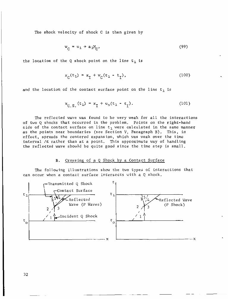
B. Crossing of a Q Shock by a Contact Sur face
The following i l l u s t r a t i o n s show the two types of i n t e r a c t i o n s t h a t can occur when a con tac t s u r f a c e i n t e r s e c t s w i t h a Q shock.
t
Contact Surface
Wave ( P Waves) (P Shock)
nc iden t Q Shock t 0
t . 0
32
I f the p re s su re r a t i o across the t r ansmi t t ed Q shock p5 /p2 is l e s s than the p re s su re r a t i o ac ross the i n c i d e n t Q shock p3/p1, then the r e f l e c t e d wave is a r a r e f a c t i o n fan. However, i f p5/p0 > p3/p1, t h e r e f l e c t e d wave i s a P shock. I n the cases c a l c u l a t e d f o r the problem a t hand i n which a con tac t su r f ace c ros s ing a Q shock occurred, the r e f l e c t e d wave was always a weak r a r e f a c t i o n fan . w a s coded f o r t he case of only the r e f l e c t e d wave being a r a r e f a c t i o n f a n , b u t maintaining the c a p a b i l i t y of d e t e c t i n g i f the r e f l e c t e d wave i s a P shock and p r i n t i n g o u t a message desc r ib ing t h i s cond i t ion and the s t r e n g t h of the P shock. The r a r e f a c t i o n f a n i s handled i n the same manner as t h a t descr ibed i n the previous s e c t i o n when two Q shocks i n t e r a c t .
The computer program
The i n t e r a c t i o n of the contact s u r f a c e and a Q shock was solved by an approximate t r i a l - a n d - e r r o r procedure. s e c t i o n p o i n t , t he s u b s c r i p t s 1 through 5 r e f e r t o the regions ind ica t ed i n the i l l u s t r a t i o n s , and A and B r e f e r t o t h e i n c i d e n t and t r ansmi t t ed Q shocks, r e s p e c t i v e l y . Flow p r o p e r t i e s i n r eg ions 1, 2 , and 3 are assumed known. Ca lcu la t ion s t e p s f o r s o l v i n g the i n t e r a c t i o n process a r e as fol lows:
Let xI, tI r e f e r t o the i n t e r -
(1) Consider t h a t the v e l o c i t y i n r eg ion 5 (u5) has been given from the previous i t e r a t i o n cycle o r f o r the f i r s t cyc le has been guessed.
(2) The remaining p r o p e r t i e s i n r eg ion 5 can then be c a l c u l a t e d from the Rankine-Hugoniot r e l a t i o n s a c r o s s a Q shock:
"B 2
(105)
33
( 3 ) Since i t has been assumed t h a t t he r e f l e c t e d wave i s a r a r e f a c t i o n fan, t he re i s no change i n en t ropy a c r o s s t h e r e f l e c t e d wave; i . e . , S 4 = S 3 . The speed of sound i s then g iven by s a t i s f y i n g t h e bound- a r y condi t ion of equal p re s su re through the con tac t s u r f a c e ,
L a4 = a5e
( 4 ) An a d d i t i o n a l cond i t ion t h a t m u s t be s a t i s f i e d is t h e con- s t ancy of the c h a r a c t e r i s t i c v a r i a b l e Q a c r o s s the expansion f an
which by d e f i n i t i o n y i e l d s the r e l a t i o n s h i p f o r t he v e l o c i t y i n r eg ion 4 .
( 5 ) The second boundary cond i t ion ac ross t h e c o n t a c t s u r f a c e i s now s a t i s f i e d by s e t t i n g
ug = u 4
which then provides the improved va lue f o r u 5 i n t he next i t e r a t i o n cyc le .
S teps (2 ) through (5) are repea ted u n t i l t he prescr ibed to l e rance f o r t h e d i f f e rence i n success ive va lues of u 5 i s m e t .
The loca t ion of the shock and con tac t s u r f a c e p o i n t s , and the c a l - c u l a t i o n of points on the r i g h t s i d e of t he con tac t s u r f a c e by the charac- t e r i s t i c s o l u t i o n a t time tl , fo l low t h e same procedure descr ibed i n the previous s e c t i o n when two Q shocks i n t e r a c t .
I X . E X I T CONDITIONS
A f t e r diaphragm r u p t u r e , the volume of gas t h a t has been compressed on the lef t -hand s i d e of t he diaphragm flows through the f a c i l i t y and empties i n t o a r e s e r v o i r which i s connected t o the end of t he d u c t .
34
Since the mathematical s o l u t i o n i s intended t o c a l c u l a t e only the e a r l y development of the flow, i t is not necessary t o include the cond i t ions f o r inf low a t the end of the d u c t . The p o s s i b i l i t y of inflow a t the e x i t could e x i s t only a t a ve ry l a t e time because of a bui ldup of p re s - s u r e i n the emptying r e s e r v o i r , or a t a ve ry l a t e s t a g e of the blowdown i f emptying i n t o the atmosphere.
For the problem a t hand, gas is always assumed t o be leaving the d u c t a t the e x i t s t a t i o n Lo and i s t h e r e f o r e t r e a t e d as an outf low problem. The gas i n the e x t e r n a l region i s assumed t o be a t r e s t . The c a l c u l a t i o n procedure f o r s a t i s f y i n g t h e a p p r o p r i a t e boundary cond i t ions f o r subsonic , s o n i c , or supersonic flow a t the e x i t i s now given.
A. Subsonic Flow a t E x i t
For subsonic flow it is assumed t h a t the p re s su res on each s i d e of t h e e x i t plane fol low the s t e a d y s t a t e boundary cond i t ion of equal p r e s s u r e . Since we have chosen the condi t ions which were on the r i g h t s i d e of the diaphragm be fo re rupture as the r e f e r e n c e s t a t e , the p re s - s u r e a t the e x i t is given by p~ = p~~ = 1 where the s u b s c r i p t s EL and ER r e f e r t o the l e f t - and right-hand s i d e s of the e x i t plane, respec- t i v e l y . The i t e r a t i o n procedure t o c a l c u l a t e t he flow p r o p e r t i e s a t the e x i t is as follows:
(1) The v e l o c i t y uE is given by the previous i t e r a t i o n cyc le , o r f o r the f i r s t cycle i s gueksed.
(2) The entropy SE a t the e x i t i s given by the conventional procedure as f o r a r e g u l a r p o i n t (Section V, Paragraph A).
(3) Applying the boundary cond i t ion p = 1 a t the e x i t r e s u l t s i n t h e following equat ion f o r t he speed of sound, we o b t a i n
which includes the cond i t ions t h a t the p r o p e r t i e s on the r i g h t s i d e of t he e x i t plane a r e the r e f e r e n c e s t a t e and the r e f e r e n c e entropy i s zero.
( 4 ) The va lue f o r the P c h a r a c t e r i s t i c PE a t the e x i t i s found i n the same manner as f o r a r egu la r p o i n t . n i shes a r e l a t i o n fo r t h e v e l o c i t y :
T k i s va lue then f u r -
2 = p - - U ~ L E~ - 1 a ~ L *
35
Steps (2) through ( 4 ) a r e repeated u n t i l t he change i n u f o r sub- sequent i t e r a t i o n cycles i s l e s s than a p resc r ibed to l e rance . EL
\
X. SOME PERTINENT DETAILS ABOUT THE CALCULATION PROCEDURE
B. Sonic Flow a t E x i t
The boundary cond i t ion t o be s a t i s f i e d f o r s o n i c flow a t the e x i t is uE = aEL. condikions a t the e x i t i s as follows:
The t r i a l - a n d - e r r o r procedure t o c a l c u l a t e the s o n i c flow
(1) Assume t h a t t he v e l o c i t y U E ~ has been given from the previous i t e r a t i o n cycle or f o r the f i r s t cyc le has been guessed.
(2)
(3 ) Values f o r the entropy SE
S a t i s f y the boundary cond i t ion by s e t t i n g aEL = uEL,
L and c h a r a c t e r i s t i c P E ~ a r e found by the standard procedure (Sect ion V, Paragraph A).
( 4 ) A new va lue f o r UE i s given by L
Steps ( 2 ) through ( 4 ) a r e repeated u n t i l the change i n uEL fo r sub- sequent i t e r a t i o n cycles is l e s s than a p resc r ibed t o l e r a n c e .
C . Supersonic Flow a t E x i t
For supersonic outflow, the e x i t cond i t ions can be c a l c u l a t e d by the s t anda rd procedure s i n c e both P and Q c h a r a c t e r i s t i c s reach the e x i t .
A . Geometrical Aspects
E f f e c t s on the flow p r o p e r t i e s due t o the change i n c ros s s e c t i o n a r e f e l t through the term
which appears i n both c h a r a c t e r i s t i c equat ions. Information concerning the geometry of the duct m u s t be furnished t o t h e computer program i n a
form such t h a t the term
can be evaluated a t any p o i n t x. The a c t u a l duct shape i s approximated by a s e r i e s of s t r a i g h t l i n e segments f o r the i n s i d e diameter i n the a x i a l d i r e c t i o n . T o avoid d i s c o n t i n u i t i e s i n the f i r s t d e r i v a t i v e s of t he a r e a a t the j u n c t i o n of the l i n e segments, a parabola which con- nected the s t r a i g h t l i n e s a t a d i s t ance of E on each s i d e of t he j u n c t i o n w a s used as shown i n the i l l u s t r a t i o n .
The computer program r e q u i r e s M i npu t STRAIGHT LINE cards regarding the geometry f o r which each card con ta ins an a x i a l s t a t i o n x E ( i ) a long wi th the corresponding diameter
E ( ), and curve f i t parameter E$(i), where i = 1 , M . The l e f t end of t he supply tube
0 is r e f e r r e d t o by i = 1, and the x>k =
r i g h t end of the f a c i l i t y where x" = Lo is r e f e r r e d t o by i = M . The remaining i n d i c e s i = 2,M-1 r e f e r t o the junct ion of t he s t r a i g h t l i n e segments. The program a u t o m t ical 1 y nond imens iona 1 i z e s a1 1 d is - tances by Lo.
* d>k i
- . -- x ( i ) E
B. G r i d Control
To keep the c h a r a c t e r i s t i c grid a t a s u f f i c i e n t d e n s i t y , i t was necessa ry t o e s t a b l i s h some c r i t e r i a t o e i t h e r i n t roduce o r take ou t p o i n t s a t each time s t e p . It i s seen, f o r i n s t ance , t h a t i n regions where t h e r e is s o n i c flow, a d d i t i o n a l p o i n t s m u s t be introduced, s i n c e i n subsonic flow, the Q c h a r a c t e r i s t i c s t r a v e l t o the l e f t , and i n supe r son ic flow, they t r a v e l t o the r i g h t i n the wave diagram (see Figure 2 ) .
Whether o r no t p o i n t s should be introduced w a s determined by pre- s c r i b i n g an upper l i m i t i n the change of Q between two consecut ive p o i n t s and an upper l i m i t i n t he allowable d i s t a n c e between them. L e t t h e s e l i m i t s be r e f e r r e d t o as amax and Axmax and consider t h a t t he s o l u t i o n has been completed up t o a p o i n t j on a l i n e t = tl. The fol lowing q u a n t i t i e s a r e then ca l cu la t ed :
Y M = Q ( j ) - Q(j-1)
.& = x ( j ) - x( j -1 ) .
37
I f e i t h e r rQ o r Ax i s l a r g e r than the p re sc r ibed upper l i m i t s f o r t hese q u a n t i t i e s , any number from one t o t h r e e a d d i t i o n a l p o i n t s o r Q waves a r e introduced between x ( j ) and x ( j - 1 ) . These a d d i t i o n a l p o i n t s a r e calcu- l a t e d by the method of c h a r a c t e r i s t i c s i n a s p e c i a l sub rou t ine c a l l e d POINTADD of the computer program. The maximum al lowable d i f f e r e n c e i n Q between two a d j a c e n t po in t s LQmX i s a r equ i r ed inpu t (TOLQ) of the computer program. Values of TOLQ = .05 f o r t he subsonic cases and TOLQ = . 2 for the supersonic cases were found t o g i v e good r e s u l t s . The upper l i m i t f o r t he d i s t a n c e between any. two p o i n t s Axmax i s au to - m a t i c a l l y determined by the computer program. The va lue of Axmax i s no t cons t an t throughout t he d u c t s i n c e , i n s e c t i o n s where t h e r e a r e a r e a changes, a much denser d i s t r i b u t i o n of p o i n t s i s necessary than i n s t r a i g h t s ec t ions where t h e r e a r e no a r e a changes. The program a l s o takes o u t points au tomat i ca l ly when the g r i d becomes too dense.
By running repeated cases f o r s e v e r a l time increments, i t was found t h a t At = .001 f o r subsonic and A t = .002 f o r supersonic cases gave s a t i s f a c t o r y r e s u l t s . What i s meant by subsonic and supe r son ic cases as r e f e r r e d t o above p e r t a i n s t o the s t a t e of the flow i n the t e s t s ec - t i o n a f t e r the flow is e s t a b l i s h e d . The d i s t a n c e between the po in t s i n the a x i a l d i r e c t i o n was found t o be much more c r i t i c a l than the time i n t e r v a l i n the s e c t i o n s where the re were l a r g e a r e a changes.
C . R e s t a r t Procedure
Since each case took a f a i r l y l a r g e amount of time on the CDC 3200 computer, a r e s t a r t procedure w a s incorporated i n the program. Each time on the computer, a p re sc r ibed number of time i n t e r v a l s a r e computed and the d i s t r i b u t i o n of po in t s and t h e i r p e r t i n e n t p r o p e r t i e s f o r the l as t ca l cu la t ed time a r e punched on computer c a r d s , which a r e then used as inpu t for t he nex t run. The p repa ra t ion of i npu t f o r the program is explained i n d e t a i l i n Appendix B.
X I . DISCUSSION OF THE RESULTS
The c a l c u l a t i o n procedures descr ibed i n t h i s r e p o r t f o r the one- dimensional flow through the pressure- tube tunnel were programmed f o r the CDC 3200 computer. Ca lcu la t ions were performed f o r t he a n t i c i p a t e d range of Mach numbers f o r the f a c i l i t y . Figure 1A presen t s the ae ro - dynamic boundaries f o r the f u l l - s c a l e d f a c i l i t y w i t h the Mach 2 nozzle i n s t a l l e d . The interchangeable nozzle s e c t i o n s f o r the supersonic cases were designed from the r e s u l t s of a two-dimensional method of cha rac t e r - i s t i c s s a t i s f y i n g the cond i t ion of uniform flow a t the nozzle e x i t plane. The spool length s a t i s f i e s the cond i t ion t h a t the l e n g t h of the nozzle and spool equaled 138 inches f o r each case. The d i s t a n c e from the
38
diaphragm t o the nozzle t h r o a t was approximately 29 pe rcen t longer f o r MTEST = 3.5 and 5.0 than the corresponding l e n g t h f o r MTEST = 1.4 , 1 . 7 , and 2.04. Figure 1 B p re sen t s t h e aerodynamic boundaries of t h e tunnel w i t h the s o n i c nozzle i n s t a l l e d . This conf igu ra t ion was used f o r t he s o n i c and subsonic cases that were c a l c u l a t e d . The subsonic Mach numbers i n t h e t e s t s e c t i o n were a t t a i n e d by choking the flow downstream of t h e t e s t s e c t i o n by the use of choking f l a p s as shown i n Figure 1B. Also shown i n Figures 1A and 1B a r e imaginary o r e f f e c t i v e boundaries which w e r e assumed t o approximately account f o r blockage by the model support and diaphragm c u t t e r mechanisms.
The following i n i t i a l and r e fe rence cond i t ions were assumed f o r a l l of t he cases ca l cu la t ed :
(1) The gas on each s i d e of t he diaphragm is a i r whose r a t i o of s p e c i f i c hea t s i s y = 1.4 .
(2) The temperature of the a i r on each s i d e of the diaphragm 295.57 "K. i s T'; = T Y C =
2
(3) The p r o p e r t i e s o f the a i r on the r i g h t s i d e of the diaphragm be fo re rupture a r e :
a t = 1130 f t / s e c
p; = 14.7 l b / i n 2 = 2116.8 l b / f t 2
s, = 0.
( 4 ) The r e fe rence condi t ions a r e the s t a t e of the a i r on the r i g h t s i d e of t he diaphragm be fo re r u p t u r e .
(5) The r e fe rence l eng th i s the t o t a l l e n g t h of t he f a c i l i t y :
Lo = 325 f t .
Figure 2 p re sen t s the wave diagram f o r t he case i n which the Mach number i n the t e s t s e c t i o n during the per iod of s t e a d y flow ( r e f e r r e d t o as MEST) was two. B r i e f l y recapping what occurs during the e a r l y development of t he flow, we can see the centered expansion f a n , which i s bounded on the l e f t by the head-wave and on t h e r i g h t by the t a i l - wave, that o r i g i n a t e s a t the diaphragm l o c a t i o n a t the i n s t a n t the diaphragm r u p t u r e s . The expansion waves t h a t make u p t h i s centered expansion f a n a c c e l e r a t e s the a i r which w a s i n i t i a l l y on the l e f t s i d e of t he diaphragm s o t h a t i t s tar ts t o flow o u t through the f a c i l i t y , A l so shown i s the P shock that was formed when the diaphragm was rup tu red . The P shock a c c e l e r a t e s the s t i l l a i r through which i t passes
39
as it t r a v e l s ou t of the duc t . The pa th of t he con tac t s u r f a c e , i . e . , t he i n t e r f a c e t h a t d iv ides the two volumes of a i r of d i f f e r e n t entropy that were i n i t i a l l y i n con tac t w i th each s i d e of t he diaphragm be fo re r u p t u r e , i s shown as i t t r a v e l s ou t of t h e d u c t . Between the ta i l -wave of t h e i n i t i a l centered expansion f a n and the con tac t s u r f a c e , two Q shocks a r e formed which e v e n t u a l l y i n t e r a c t w i th each o t h e r . Created a t t h i s i n t e r a c t i o n a r e a shock s t r o n g e r than e i t h e r of t he o r i g i n a l two, a c o n t a c t su r f ace , and a weak expansion wave. A s soon as the s o n i c Mach number is reached a t the nozzle t h r o a t , no more expansion waves can pass through, and t h e r e f o r e only a n expansion f a n of f i n i t e width can t r a v e l t o t h e l e f t through the supply tube. A s h o r t time a f t e r the flow i n the t h r o a t chokes, a Q shock i s formed j u s t downstream of the nozzle t h r o a t and s lowly t r a v e l s through the remainder of t he nozzle and the t e s t s ec - t i o n . A steady flow i s e s t a b l i s h e d behind t h i s Q shock, and the s t a r t time is the re fo re defined as the time when the Q shock passes ou t of t he t e s t s e c t i o n . Some of the Q and P c h a r a c t e r i s t i c curves a r e t r aced i n the wave diagram presented i n Figure 2. It is seen t h a t the paths of t he P c h a r a c t e r i s t i c curves a r e f a i r l y uniform throughout the wave diagram, b u t t he paths of t he Q c h a r a c t e r i s t i c s do not fol low any sys t ema t i c p a t t e r n s i n the e a r l y s t a g e s of t he flow. A f t e r e s t ab l i shmen t of s t eady flow, both c h a r a c t e r i s t i c s fol low a uniform p a t t e r n ; i . e . , a t each x s ta- t i o n the slopes of both c h a r a c t e r i s t i c s a r e cons t an t i n time a f t e r e s t a b - l ishment of s t eady flow. A t any time, we cen recognize the flow regime a t any p o s i t i o n i n the f a c i l i t y by observing the d i r e c t i o n s of t he Q c h a r a c t e r i s t i c s . Subsonic Mach numbers a r e cha rac t e r i zed by the Q c h a r a c t e r i s t i c curves t r a v e l i n g t o the l e f t , s o n i c when t r a v e l i n g i n t h e v e r t i c a l d i r e c t i o n , and supersonic when t r a v e l i n g t o the r i g h t .
Figures 3 through 6 p re sen t the wave diagrams f o r t e s t Mach numbers 1 .4 , 1 . 7 , 3.5, a n d 5 . 0 . The wave diagrams f o r a l l supe r son ic cases a r e s i m i l a r t o Figure 2 , and t h e r e f o r e the Q and P c h a r a c t e r i s t i c n e t is no t shown i n Figures 3 through 6 , because t o enable one t o d r a w the charac- t e r i s t i c curves r e q u i r e s a p r i n t - o u t a t each time s t e p by the computer program. This p r i n t - o u t takes much more computer time and r e s u l t s i n volumes of paper.
Figure 7 p l o t s the s t a t i c p re s su re as a f u n c t i o n of time a t a s ta - t i o n i n the t e s t s e c t i o n f o r the supe r son ic range of t e s t s e c t i o n Mach numbers ca l cu la t ed . The drop i n p re s su re t o a cons t an t va lue a f t e r the shock passes t h i s s t a t i o n thereby e s t a b l i s h e s the s t a r t i n g time def ined as the beginning of the per iod of s t eady flow.
For the subsonic cases , the flow i s choked downstream of the t e s t s e c t i o n by choking f l a p s which a r e approximated by assumed boundaries t h a t account f o r t he f l a p s and blockage due t o the model suppor t and diaphragm c u t t e r mechanism. Cases were c a l c u l a t e d i n which subsonic and s o n i c Mach numbers of .515, - 7 , and 1 .0 r e s u l t e d i n the t e s t s e c t i o n du r ing the period of s t e a d y flow cond i t ions . For the subson ic , as i n
40
,
t he supe r son ic cases , only a n expansion f a n of f i n i t e width can pass through the t h r o a t s i n c e no more expansion waves can pass through the t h r o a t a f t e r choking occurs. Steady flow is e s t a b l i s h e d i n the t e s t s e c t i o n only a f t e r the h igh ly nonl inear e f f e c t s of a r e a changes on t h e s l o p e s of t he P and Q c h a r a c t e r i s t i c v a r i a b l e s a t each x s t a t i o n upstream of the t h r o a t have died o u t w i t h time. This e f f e c t i s i l l u s - t r a t e d i n Figure 8, which shows the p re s su re as a func t ion of time a t an a x i a l s t a t i o n i n the t e s t s ec t ion . The s t a r t i n g times f o r the sub- s o n i c and s o n i c cases a r e def ined as the times when s t eady s t a t e con- d i t i o n s a r e e s t a b l i s h e d throughout t he t e s t s e c t i o n .
S t a r t i n g times f o r a l l of the cases t h a t were c a l c u l a t e d a r e p l o t t e d i n f i g u r e 9 as a func t ion of t h e t e s t Mach number. It is seen t h a t t he subsonic and s o n i c Mach numbers r equ i r e a longer s t a r t time, s i n c e the s t eady ing of the flow p r o p e r t i e s in t h e t e s t s e c t i o n i s a gradual pro- cess whereby, f o r t he supe r son ic cases , a s t r o n g shock passes through t h e t e s t s e c t i o n t h a t i n s t a n t l y e s t a b l i s h e s a s t eady flow behind i t , The s t a r t i n g t i m e s f o r t he supersonic cases depend, however, on the speed a t which the shock t r a v e l s through the nozzle and t e s t s e c t i o n , This speed is governed by the l o c a l f low cond i t ions upstream of the shock and the s t r e n g t h of t he shock.
Figure 10 p resen t s t he ca l cu la t ed Reynolds number per f o o t i n t h e t e s t s e c t i o n d u r i n g . t h e period of s t eady flow f o r the range of t e s t Mach numbers and f o r t he maximum charge p res su re of 48.64 a t m assumed f o r t h e f a c i l i t y . It i s seen t h a t t he h i g h e s t t e s t Reynolds number of approximately 2 x l o8 pe r f o o t for t h e f a c i l i t y w i l l occur i n the v i c i n i t y of a t e s t Mach number of 1.4. Figure 10 shows one case which was c a l - c u l a t e d f o r a t e s t Mach number of 2.04 i n which the charge p res su re was assumed t o be 18.03 atm. This reduct ion i n charge p res su re r e s u l t e d i n approximately a l i n e a r r educ t ion in t e s t Reynolds number f o r t h i s p a r t i c u l a r Mach number. The e f f e c t on s t a r t i n g time by t h i s r e d u c t i o n i n charge p res su re was found t o be n e g l i g i b l e , however.
The s t a t i c p re s su re i n t h e t e s t s e c t i o n during t h e per iod of s t e a d y flow is presented as a f u n c t i o n of Mach number i n Figure 11. The expected t r end of decreasing p res su re wi th inc reas ing Mach number i s shown.
To check the e f f e c t s of t h e s e t t l i n g chamber on t h e s t a r t t ime, one case f o r M ~ S T = 2.04 was ca l cu la t ed i n which t h e s e t t l i n g chamber w a s removed. A comparison of t h e s e r e s u l t s w i t h t h e corresponding case w i t h a s e t t l i n g chamber showed a n e g l i g i b l e d i f f e r e n c e i n the s t a r t time.
The p re l imina ry a n a l y t i c a l r e s u l t s t h a t have been c a l c u l a t e d by t h < - - - - - -As. - - - * < l 1 l.- -------A v , : t h nTrnnr;mn.ntnl r n o s - 1 to v~hnn t h n G q , - ; l - L L l L 3 yLuLcuuLc W L L l " C L u L t L y c a L c : u W L L L L G * y c L L L l l G I I L Q L L G D L L A L D W I ' L L L L L l C L U b I I
i t y is completed and measured data made a v a i l a b l e . Future a n a l y t i c a l i n v e s t i g a t i o n s t o include the e f f e c t s of boundary l a y e r and mass removal of gas through the w a l l s i n t he t e s t s e c t i o n f o r t r a n s o n i c Mach numbers a r e planned.
41
t t
,oodsf-$
+ lodd P P O W s! * (+)
0
0 .L 0 0 I - m CI, c L 0)
Y) c 0 0
a
0 I
.- R
L 0
c = 0 I m
42
h w c
B
c 0
J
43
a n d I I I I I I i
9 9 9 0 6 VI N
0. 9 W Lo w t
44
.
I I 0 a 7
0 '?
I I
?
3
c
45
4
o?
IC
46
0 n 0 v)
"! 7 rl 9 0
u1 u.
I I I I I I I i OD r- W v) 0 c) N Y 0 -
*- 9 9 9 9 9 9 9 9
47
1 -
2 -
.- I- ; - v)
I I I 0 0 0 c! ‘u 7.
48
L
I .I .3
I h I
t ( *
p (atm)
50
40
30
20
10
0
I I I I 1 -
0 .025 .050 .0\5 A00 .I 25 t" (sec)
FIG. 7. PRESSURE A S A FUNCTION OF TIME
AT A STATION I N THE TEST SECTION
FOR SUPERSONIC TEST MACH NUMBERS ~-
Drop in Pressure' Due MTEST 4 . 4 7 To Shock Passing
ih ,
49
5 0
4 5
4 0
3 5
3 0
2 5
20
1 5
1 1.0
0.1 0.2 0.3 0.4 0.5 t ( - 1
I 0 ,025 ,050 ,075 A00 .I 25 .I150
t * ( s e d
FIG. 8. PRESSURE AS A AT A STATION I N THE
FOR SUBSONIC AND SONIC
FUNCTION OF T I M E
E S T MACH NUMBERS T E S T SECTION
.
50
c I I
9 0 In 7.
a W
c v) W c IL 0
e 4 c v)
a
51
Y 0
E w m a z
I 0 4 I
+ v) W t
LL 0
z 0 t 0 z = LL
4
v) 4
-
a W m
t v) W t
0 T-
c3 LL -
52
P
c u) m I-
t
a
L
53
REFERENCES
1.
2.
3.
4 .
5.
6.
7.
8 .
9.
10.
11.
12.
13.
54
B u l l , G. V . , " S t a r t i n g Processes i n an I n t e r m i t t e n t Supersonic Wind Tunnel," UTIA Report No. 12 , Un ive r s i ty of Toronto, February 1951.
B u l l , G. V . , " I n v e s t i g a t i o n i n t o the Operating Cycle of a Two-Dimen- s i o n a l Supersonic Wind Tunnel," J o u r n a l of t h e Aeronaut ica l Sciences, September 1952.
Cable, A. J . , R. N . Cox, "The Ludwieg Pressure-Tube Supersonic Wind Tunnel," The Aeronaut ical Q u a r t e r l y , p . 143-157, May 1963.
Cox, R . N . , "Discussion Following the P r e s e n t a t i o n o f Papers on Hypersonics," AGARD Reports 132-147, p. 28, Ju ly 1957.
D a h , W . K . , "Discussion of a Proposed High Reynolds Number Test F a c i l i t y , " Aero I n t e r n a l Note No. 21-65, MSFC, September 1965.
Hartree, D. R . , "Some P r a c t i c a l Methods of Using C h a r a c t e r i s t i c s i n the Ca lcu la t ion of Non-Steady Compressible Flow," United S t a t e s Atomic Energy Commission, AECU-2713, September 1953.
Ludwieg, H. , "Der Rohrwindkanel Z e i t s c h i f t f u r Flugwessenschaften," Jahrgang 3, Heft 7 , p. 206, J u l y 1955.
Ludwieg, H., "Tube Wind Tunnel - A Spec ia l Type of Blowdown Tunnel," J u l y 1957, North A t l a n t i c T rea ty Organizat ion Advisory Group f o r Aeronaut ical Research and Development, Report 143.
Rudinger, G . , Wave Diagrams f o r Nonsteady Flow i n Ducts, D. Van Nostrand Company, Inc . , New York, 1955.
B u l l , G. V . , Fowell, L. R . , and Henshaw, D. H. , "The I n t e r a c t i o n of Two S imi l a r ly 'Fac ing Shock Waves," Jou rna l of Aeronaut ica l Sciences, pp. 210-212, March 1954.
Davis, J . W . , and Gwin, H. S . , " F e a s i b i l i t y S tud ie s of a Shor t Dura- t i o n High Reynolds Number Tube Wind Tunnel," MSFC TM X-53571, January 1967.
P a i , S. P . , I n t r o d u c t i o n t o t h e Theory of Compressible Flow, D. Van Nostrand Company, I n c . , New York, 1959.
Shapiro, A. H. , Compressible F lu id Flow, Vol. 1, The Ronald P res s Company, New York, 1953.
J
APPENDIX A
Derivat ion of t he C h a r a c t e r i s t i c Equations
The b a s i c d i f f e r e n t i a l equations (1) through ( 4 ) can be w r i t t e n i n nondimensional form (see D e f i n i t i o n of Symbols) as:
Con t inu i ty
Moment um
Equation of S t a t e
a2 = E = T. P
F i r s t Law of Thermodynamics
1 In E - - I n p . s - s o - - - Y - 1 P Y
(A- 3 )
(A- 4 )
Some u s e f u l r e l a t i o n s t h a t r e s u l t from the combining of equations (A-3) and ( A - 4 ) a r e
(A- 5a)
(A- 5b)
(A- 5 C )
55
Due t o the r e l a t i o n s (A-5a) through (A-5c), t h e c o n t i n u i t y equa t ion (A-1) can be expressed as
-- A) A) 2 aa aU 2 a a 7 - i a t y - l ax ax ax a t - a + - ~ - + a - = - a u
and the momentum equat ion as
- + u aU -+-a aU 2 & = a 2 & + f . at ax - 1 ax ax (A-7)
Adding equat ion (A-7) t o equa t ion (A-6) r e s u l t s i n the fol lowing equat ion:
a(1n A) a(1n A) + ya (E + - a -,,) as a t Y ax - a ax -au - + ( u + a ) - = ap aP a t ax
The s u b s t a n t i a l d e r i v a t i v e i n the x , t - p l a n e i s def ined as
Le t t he d i f f e r e n t i a l ope ra to r
56
- = L + ( u + a ) - 6+ a 6t a t ax
(A- 10)
(A-11)
r e p r e s e n t t he change of a parameter i n the d i r e c t i o n
- = dx u + a d t
i n the x , t - p l a n e . Equation (A-8) can then be w r i t t e n as
S u b t r a c t i n g equat ion (A-7) from (A-6) y i e l d s
where
2 Q = - a - u .
Y - 1
Let t he d i f f e r e n t i a l ope ra to r
&- a a 6 t a t + (u e a ) ax - = -
r e p r e s e n t t he change of a parameter i n a d i r e c t i o n
i n t h e x , t -p l ane . Equation (A-14) can then be w r i t t e n as
(A- 1 2 )
(A- 13)
(A- 14 )
(A- 15)
(A- 16)
(A-17)
57
A t h i r d r e l a t i o n i s r equ i r ed t o complete the system f o r the t h r e e dependent v a r i a b l e s a , u , and S . Given by the entropy cond i t ion which m u s t be prescr ibed f o r any problem,this r e l a t i o n i s given h e r e i n a gene ra l form as
DS (A-19) - = D t F(a>uYSYxYt)*
Equations (A-13), (A-18), and (A-19) form the system of equat ions t h a t m u s t be solved f o r the t h r e e dependent v a r i a b l e s u , a , and S . These equat ions a r e solved by a s tep-by-step procedure along the c h a r a c t e r i s t i c curves P , Q , and S i n the x , t - p l a n e . The d e t a i l s of s o l v i n g these equa- t i o n s a r e presented i n o t h e r s e c t i o n s of t h i s r e p o r t .
1
58
APPENDIX B
The For t r an Program and I ts Input Data
1. P repa ra t ion of the Inpu t Data f o r t h e Computer Program
The computer program and the sub rou t ines employed by the pro- gram a r e w r i t t e n i n F o r t r a n IV language f o r t he CDC 3200 computer i n P a r t 2 of t h i s Appendix. To run the program, the fol lowing inpu t cards m u s t be prepared:
C a r d No. Columns For t r an Symbol
1 1-14 TOL
2
15-28 TOLQ
29-42 P2P1
43-56 A 2
1-14 G
1
15-28 XREF
Format
E14.8
E14.8
E14.8
E14.8
E14.8
E14.8
Des c r i p t ion
Tolerance f o r which a l l s o l u t i o n s ca l cu la t ed by a n i t e r a t i o n procedure i s s a t i s f i e d .
Maximum d i f f e r e n c e QMAx between the va lues of t he c h a r a c t e r i s t i c Q f o r neigh- bo r ing Q waves (see Sec- t i o n X, Paragraph B) .
R a t i o of the p re s su re on the l e f t -hand s i d e of the d i a - phragm t o t h a t on the r i g h t b e f o r e rup tu re (pz/p;).
Nondimens iona l speed of sound on l e f t s i d e of d i a - phragm be fo re rup tu re ; s e e equa t ion (33).
Ra t io of s p e c i f i c h e a t (y) . The program assumes t h a t the gases on both s i d e s of t he diaphragm have the same va lue f o r y.
To ta l f a c i l i t y l e n g t h (Lo) by which a l l d i s t a n c e s a r e nond imens iona l ized .
59
Card No. Columns
29-42
43-56
57-59
3 t o M+2 1-13
15-28
29-42
M+3 1-14
15-17
18-20
M+4 1-15
For t r an Symbol
XD
XTEST
M
XE
DE
EPS
DT
NUMT
NPRNT
T
Format
E14.8
E14.8
I 3
E14.8
E14.8
E14.8
1114.8
I 3
I 3
E15.8
Des c r i p t ion
Diaphragm l o c a t i o n ($).
Axial l o c a t i o n ( X ~ S T ) i n t e s t s e c t i o n f o r which p r e s s u r e and Mach number a r e determined and p r i n t e d o u t .
Number of cards used i n des c r i b ing t unne 1 geome t r y (see Sec t ion X, Paragraph A ) .
Axial s t a t i o n (x; f o r which diameter and curve parameter a r e g iven .
Diameter (dg) of the a x i a l l y symmetric duct a t x'?
Curve f i t parameter (E';) a t xE (see Sec t ion X, Paragraph A).
E '
E
Nondimens i o n a l time i n t e r v a l
Number time s t e p s t o be loca ted .
P r i n t o u t frequency.
Nondimens i o n a l time .
For T > 0, the program incorpora t e s a r e s t a r t procedure that r e q u i r e s information from the l a s t c a l c u l a t e d time i n o rde r t o resume c a l c u l a t i o n s . This information i s contained i n a number of cards that have been au tomat i ca l ly prepared a t t he t e rmina t ion of t he previous run. Therefore , f o r T > 0, the input d a t a , beginning wi th card #M+4 p l u s the remaining required input , is a u t o m a t i c a l l y prepared a t the t e rmina t ion of t h e previous run.
For T = 0, card #M* i s the l a s t i npu t d a t a card.
60
4
1
61
6 3
.
65
.
.
67
1 3
2Q 21
27
27
2 4
1
5 9 5 9 6n
61
6 7
6 7
68
GO Tn 52 5 6 C A L L I N 1 kH(2 , I Y , 1, X G , C G , X S , S S )
5 5
69
4
7 1
7 2
7 3
3 2 0 0 F O R T R A N ( 2 . 1 . 0 ) / ( R T S )
I
1s 3
4 5
2 n 24
5 7 s 0
1 0 11
13 1 7
8
75
87
6n
6 1
6 7
6 3
6 4
8 4
8 5
86
7 6
.
7 7
I 78
J
79
i I J
I O IO I d IO I U i f3 r3 +
I O
1 ) 1 ) 11
c
3 2 0 0 F O R T R A N ( 2 . 1 . 0 ) / ( R T Z )
c
4
81
L
32110 FOt?TRAN (2.1.0 ) / ( R T S 1
.
’ - I
83
A
.
a4
.
85
.‘
87
c
-A
89
1
2 3 4
5
6 7
8
9
..'
c
90
1. 2
3 4 5
6 7 A
9
10 YDISR=XQCS NQ0CS=2
11 CONTINUE RETURN END
9 1
S U R R O U T I hE P H U C K ( 10, h , N N )
3 2 0 0 c O R T f i A l v U I A G N C S T I C R E S U L T S - FOR I N T E R
93
APPROVAL NASA TM X-53769
APPLICATION OF THE CHARACTERISTIC METHOD I N CALCULATING THE TIME DEPENDENT, ONE-DIMENSIONAL, COMPRESSIBLE FLOW
I N A TUBE W I N D TUNNEL
by John D . Warmbrod and Heinz G. S t r u c k
The informat ion i n t h i s r e p o r t has been reviewed f o r s e c u r i t y c l a s - s i f i c a t i o n . Review of any in fo rma t ion concerning Department of Defense o r Atomic Energy Commission programs has been made by t h e MSFC S e c u r i t y C l a s s i f i c a t i o n O f f i c e r . This r e p o r t , i n i t s e n t i r e t y , has been d e t e r - mined t o be u n c l a s s i f i e d .
This document has a l s o been reviewed and approved f o r t e c h n i c a l accuracy .
Werner T U K. D a h
Chief , Aerophysics Div i s ion
~~
E. D. G e i s s l e r D i r e c t o r , Aero-As trodynamics Laboratory
h
c
D I S TRIBUT I O N
D I R
DEP-T
R-DIR
MS-IP
MS-IL (8)
MS-T ( 6 )
PAT
I-RM-M
MS-H
R-AERO D r . G e i s s l e r M r . Jean M r . Reed M r . Murphree M r . D a h M r . Holderer M r . L ins l ey M r . Wilson M r . F e l i x D r . Krause M r . S t ruck M r . Warmbrod (15) M r . Sims M r . Andrews M r . J. Johnson M r . Ramsey M r . Dunn M r . Weaver M r . Davis M r . Donehoo M r . Hensen M r . Wilhold M r . J . Jones M r . L. Schutzenhofer
Sandia Corp. Livermore, C a l i f . Attn: G. R. Otey
Arnold Engr. Dev, Center Tullahoma, Tennessee Attn: M r . Palco
M r . Davis
Corne 11 Aeronaut ical Laboratory 4455 Genessee S t . P. 0. Box 235 Buffalo, New York At tn : J i m Martin
P r ince ton Un ive r s i ty The James Forres tal Campus Gas Dynamics Lab. P r ince ton , N . J . Attn: P ro f . Seymour Bogdonof f
Lewis Research Center Cleveland , Ohio Attn: G. Mandel, L i b r a r y
Ames Research Center Moffet t F i e l d , C a l i f . Attn: J. Lloyd Jones
Langley Res. Center ( 2 ) Hampton, Ca. Attn: Aero-Physics Div. , Res. Ofc.
J. V. Becker Robert Trimpi
S c i . & Tech. In fo . F a c i l i t y ( 2 5 ) P. 0. Box 33 College Park, Md. 20740 Attn: NASA Rep. (S-AK/RKT)
Mart in M a r i e t t a Corp Nuclear Div. Baltimore, Md, Attn: A . J . Cu lo t t a
Tulane Univ. New Orleans, La. At tn: Chemical Engr. Dept.