Application of the sound substructure modification method Peters, A.A.A. Published: 01/01/2001 Document Version Publisher’s PDF, also known as Version of Record (includes final page, issue and volume numbers) Please check the document version of this publication: • A submitted manuscript is the author's version of the article upon submission and before peer-review. There can be important differences between the submitted version and the official published version of record. People interested in the research are advised to contact the author for the final version of the publication, or visit the DOI to the publisher's website. • The final author version and the galley proof are versions of the publication after peer review. • The final published version features the final layout of the paper including the volume, issue and page numbers. Link to publication Citation for published version (APA): Peters, A. A. A. (2001). Application of the sound substructure modification method: using an Audi A4 Avant. (DCT rapporten; Vol. 2001.052). Eindhoven: Technische Universiteit Eindhoven. General rights Copyright and moral rights for the publications made accessible in the public portal are retained by the authors and/or other copyright owners and it is a condition of accessing publications that users recognise and abide by the legal requirements associated with these rights. • Users may download and print one copy of any publication from the public portal for the purpose of private study or research. • You may not further distribute the material or use it for any profit-making activity or commercial gain • You may freely distribute the URL identifying the publication in the public portal ? Take down policy If you believe that this document breaches copyright please contact us providing details, and we will remove access to the work immediately and investigate your claim. Download date: 02. Jun. 2018
Transcript
Application of the sound substructure modificationmethodPeters, A.A.A.
Published: 01/01/2001
Document VersionPublisher’s PDF, also known as Version of Record (includes final page, issue and volume numbers)
Please check the document version of this publication:
• A submitted manuscript is the author's version of the article upon submission and before peer-review. There can be important differencesbetween the submitted version and the official published version of record. People interested in the research are advised to contact theauthor for the final version of the publication, or visit the DOI to the publisher's website.• The final author version and the galley proof are versions of the publication after peer review.• The final published version features the final layout of the paper including the volume, issue and page numbers.
Link to publication
Citation for published version (APA):Peters, A. A. A. (2001). Application of the sound substructure modification method: using an Audi A4 Avant.(DCT rapporten; Vol. 2001.052). Eindhoven: Technische Universiteit Eindhoven.
General rightsCopyright and moral rights for the publications made accessible in the public portal are retained by the authors and/or other copyright ownersand it is a condition of accessing publications that users recognise and abide by the legal requirements associated with these rights.
• Users may download and print one copy of any publication from the public portal for the purpose of private study or research. • You may not further distribute the material or use it for any profit-making activity or commercial gain • You may freely distribute the URL identifying the publication in the public portal ?
Take down policyIf you believe that this document breaches copyright please contact us providing details, and we will remove access to the work immediatelyand investigate your claim.
6. Validation of calculated modified interior sound pressure levels
7. Conclusions
References
Appendices
I Technical specifications of AUDI A4 Avant (711-307, IN-W-4613)
II a&b Definition measurement points on Audi A4 Avant
III LMS set-up measurements with hammer excitation
IV LMS set-up APS measurements with rolling road
V LMS set-up FRF measurements with rolling road
VIa -d Influence of the reference on (Pk,road) new
VII' & b Optimised masses and mass combinations
VIII List of validation measurements
IXa-
u Comparing measured and calculated sound pressure levels
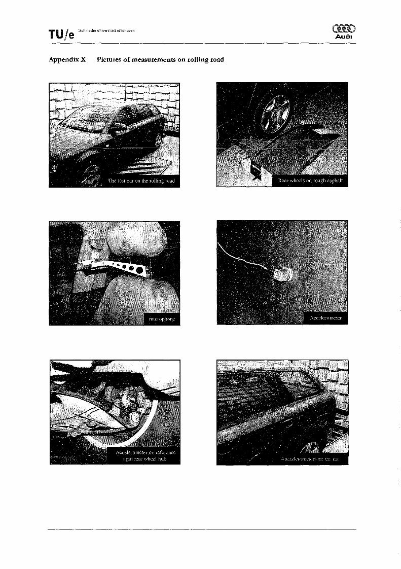
X Pictures of measurements using rolling road
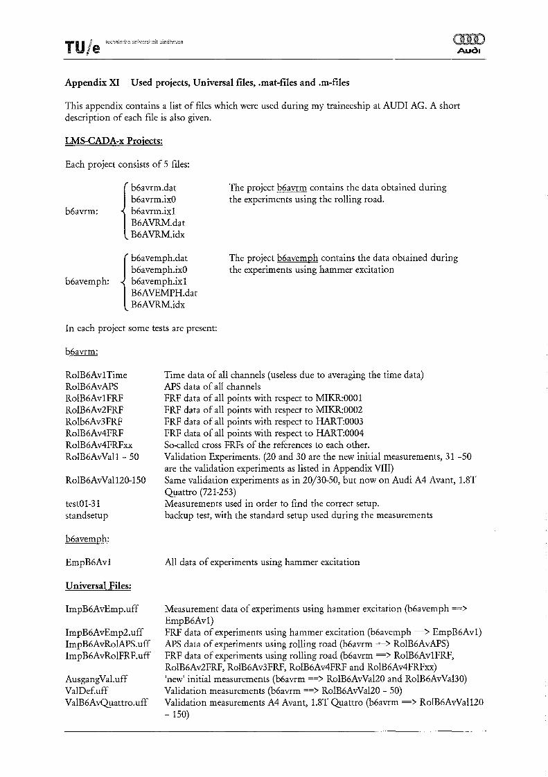
XI Used projects, Universal files, .mat-files and .m-files
XII Validation measurements using an Audi A4 Avant l.8I Qyattro
Application of the sound substructure modification method
- 1 -
2
3
4
7
7
8
9
10
12
13
16
19
20
TU/e tHn;1ische universiteit eindhoven (lID
Audl
Introduction
Reduction of interior vehicle road-noise, specifically the low-frequency "booming nOISe, is an important comfort target in the development of a new car model. Structural vibrations of the car-body are often responsible for the low frequency noise, but the relationship between the interior sound level and the car body vibrations is not straightforward. In the past an analytical-experimental method that permits the prediction of interior sound level variations due to the local coupling of defined subsystems has been developed at AUDI AG. The method has been derived from the substructure analysis used in structural dynamics. It has been extended to a hybrid acoustical/structural formulation, applied on a system constituted of the interior passenger car cabin and the car-structure. This method is known as the "Sound Substructure Modification Method" or the "Impedance-method". During my traineeship at AUDI AG in Ingolstadt this method has been applicated on an Audi A4 Avant. Booming noise, road-excited, is typically seen in combi/stationcar like cars. Goal of this trainees hip is to make the "Impedance-method" a workable tool for AUDI AG, so that it can be used more easily for future, new car-models. Secondly, an optimisation routine has to be implemented. In this way it becomes possible to calculate the optimal modifications of the car, with respect to the minimisation of the "booming noise".
Application of the sound substructure modification method
-2-
TU Ie technische uni',ersiteil eindhoven mID Audl
1. Booming noise
Reduction of interior vehicle road-noise, specifically the low-frequency booming-noise, is an important comfort target in the development of a new car model. But what is in fact this so called booming-noise? The booming-noise inside a passenger car mostly occurs when the car is driving at low speeds of about 25 to 50 km/h. When the car hits an irregularity at this speed (e.g. rough asphalt, a small bump etc.) the booming noise can increase to an unacceptable level. Structural vibrations of the car-body are often responsible for this low-frequency noise. The frequency range in which this noise occurs, is about 30 to 50 Hz. As can be seen in figure 1.1 the booming noise is not the same inside the entire car. For the A4 Avant, which was the topic in this trainees hip, the booming noise mostly occurred at the front seats of the car. This is typically for so called stationwagen cars, like, for example, the A4 Avant. In these cars the booming noise is more a problem than in other cars, because the internal cavity space is much larger. Therefore, low frequency noise is able to resonate inside the car, and so amplifYing the booming nOIse.
Application of the sound substructure modification method
-3-
TU I Iechnisch€ un:'lersiteit eindhoven
lie II
2. Description of the sound substructure modification method
Vehicle interior noise generally results from structural vibration (radiation and transmission) and airborne sound. In the low-frequency range there is further the interaction with the first acoustic cavity modes. In order to obtain a quantitative relationship between the interior sound pressure and the vibration of the surrounding body-structure, the sound substructure modification method has been developed. The basic approach of the sound substructure modification method is to identifY and predict the structural contribution of a sound resonance by only using the measured sound and acceleration data.
Consider the testing of an entire car as seen in figure 2.1, where one excitation FA is applied at location
A. The frequency response function (FRF) G k A
of the interior sound pressure at the passenger ear
positions k to the global excitation FA' and the
FRF of the acceleration of the surrounding
structure at point B, G B A' are measured, using
hammer- or shaker excitation. It is assumed that the system is linear so that the superposition principle may be applied:
XB,A
Figure 2.1 Single excitation FA at location A
(1)
(2)
The subscript k denotes the position where the sound pressure is measured, B the position of the accelerometer and A the location where the excitation force is applied. The coupled system of structure and internal cavity is described by the equations (1) and (2), where the sound pressure and the structural
vibration acceleration are uncoupled. Gk A contains the contribution of the whole structure. How the
structural vibration at point B contributes to the
global sound transfer relation Gk A is unknown.
Let us consider a local excitation, FB as seen in
figure 2.2. The sound and the local structural
FRFs, G k,B and G B,B can be measured, and a set
of equations, similar to (1) and (2) is obtained. Figure 2.2 Local excitation FB at location B
(3)
(4)
Theoretically Gk,B contains the contributions of all radiating surfaces although only one panel was
locally excited at point B. If the excitation is small enough, it is reasonable to assume that a local vibration around point B will only be generated by the excitation at point B , and the vibrations from all other structural parts will be neglectible small. Then Gk,B mainly contains the contribution of the
structure around point B .
Application of the sound substructure modification method
-4-
T U l I€-chillsche lmiverslteit eindhoven ,eee "
When both forces FA and FB act simultaneously on the vehicle, then the result for this linear assumed
system is the sum of equations (1), (2) and (3), (4):
(5)
(6)
Although equation (5) is only a simple sum of equations (1) and (3), it plays an important role in the newly developed sound substructure modification method. This equation makes it possible to analyse the sensitivity of the sound pressure at a point in the interior space to a point on the surrounding structure.
Now consider a structural modification at position B , which can be seen as the coupling of an additional system C, at position B (figure 2.3). The transfer function of the additional system is given by equation (7):
(7) Figure 2.3
Coupling of additional system C
It is assumed that the system C is rigidly joined at point B on the vehicle body and that further no external forces act at point B, then the continuity and equilibrium equations are given by equations (8) and (9):
(8)
(9)
By combining equations (5) to (9), under the assumption that FA is known, a system of five equations
with five unknown quantities (Pk' X B' X e' FB and Fe) is obtained. Equations (6) and (7) can be
combined and rewritten in equation (11), with use of the definition of He e' as given in equation (10):
(10)
(11)
Substitution of equations (10) and (11) in equation (9) and implementing equation (8) results In
equation (12):
(12)
The substitution of this last equation into equation (6) delivers a new formula for the force FB :
Application of the sound substructure modification method
-5-
(13)
rUle "
technlscne !Jl1iversiteit eindhoven
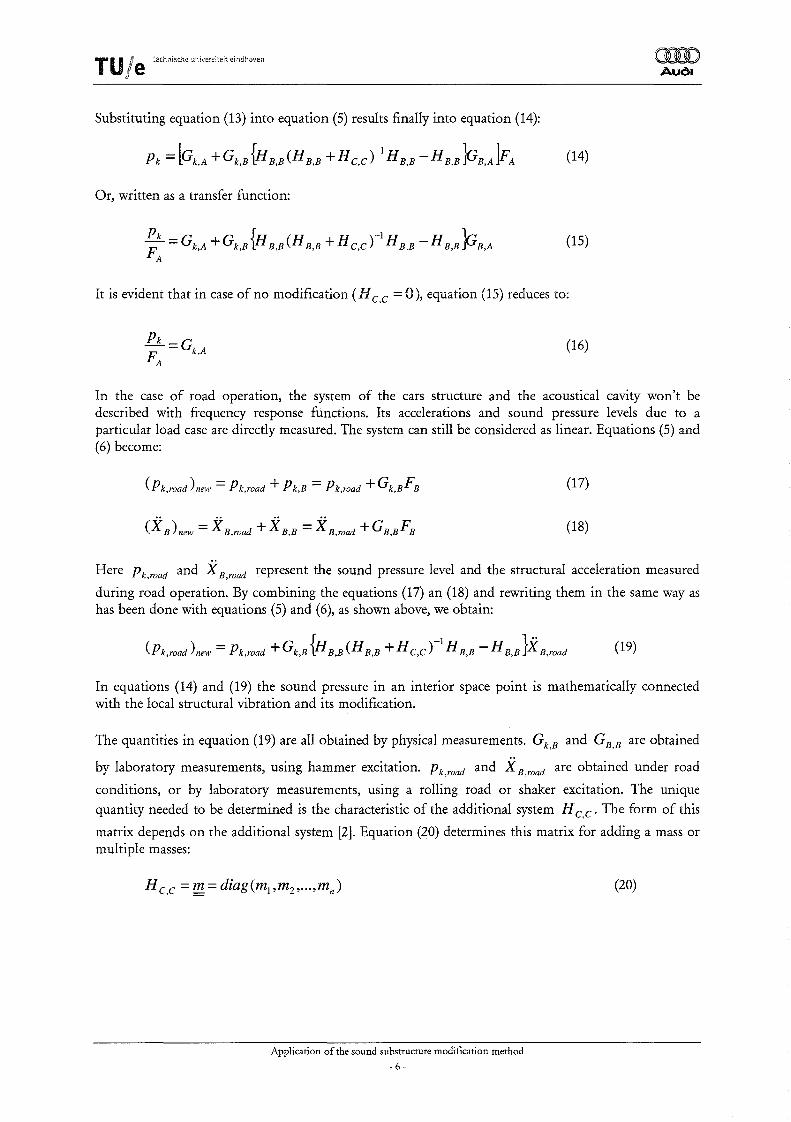
Substituting equation (13) into equation (S) results finally into equation (14):
Pk = [Gk,A + Gk,B {H B,B(H B,B + H e,e)-I H B,B -H B,B PB,A]FA (14)
It is evident that in case of no modification (H e,e = 0), equation (15) reduces to:
(16)
orm Audl
In the case of road operation, the system of the cars structure and the acoustical cavity won't be described with frequency response functions. Its accelerations and sound pressure levels due to a particular load case are directly measured. The system can still be considered as linear. Equations (S) and (6) become:
(17)
(18)
Here Pk,road and X B,road represent the sound pressure level and the structural acceleration measured
during road operation. By combining the equations (17) an (18) and rewriting them in the same way as has been done with equations (S) and (6), as shown above, we obtain:
(Pk,road ) new = Pk,road + Gk,B {H B,B (H B,B + H e,e )-1 H B,B - H B,B}X B,road (19)
In equations (14) and (19) the sound pressure in an interior space point is mathematically connected with the local structural vibration and its modification.
The quantities in equation (19) are all obtained by physical measurements. G k Band GB,B are obtained
by laboratory measurements, using hammer excitation. Pk,road and X B,road are obtained under road
conditions, or by laboratory measurements, using a rolling road or shaker excitation. The unique
quantity needed to be determined is the characteristic of the additional system H e,e' The form of this
matrix depends on the additional system [2]. Equation (20) determines this matrix for adding a mass or multiple masses:
Application of the sound substructure modification method
- 6-
(20)
T U l e tech";sch. univers",te!t eindhcven
3. Measurements
As described in the previous chapter, the quantities from equation (19) are all obtained by physical
measurements. Two kinds of measurements are required. Gk Band GB B are obtained by laboratory , ,
measurements, using hammer excitation. Pk,road and it B,road are obtained under road conditions, or
by laboratory measurements, using a rolling road. In this case these quantities are obtained by using a rolling road, because measurements in real-life, road conditions, are to complicated and cost to much
time to be performed during this traineeship. Also is assumed that for the matrix H c,c only additional
masses are applied.
During this traineeship an AUDI A4 Avant has been used for all experiments. For technical specifications of this car, see appendix I. Before the measurements are being performed, one has to compose a list of points on the car, on which one eventually wants to apply a additional mass. It seems obviously, but only for points of which all the data is measured, the effect of an additional mass on the interior sound pressure level can be calculated. In this case, 28 measurement points have been defined. The choice of those points has been made, after some initial measurement in which the sensitivity of particular points has been evaluated. Knowledge at AUDI AG about parts of the car that are important to the booming noise has also been used. The list of points is specified in appendix II.
Measurements at AUDI AG in Ingolstadt are performed using LMS CADA-X Software. The data retrieved in the experiments can be exported into Universal-files, which can be imported into MATLAB (MATLAB 6.1, reI. 12.1). Therefore, the program pro j ec t_admin . m can be used, which has been developed in the past at AUDI AG. The exact procedure is described in the Instruction Manual: Using the sound substructure modification method in MATLAB [7].
3.1. Obtaining Gk,B and GB,B
The quantities Gk,B and GB,B are obtained by laboratory measurements, using hammer excitation.
Gk,B is the frequency response function of the interior sound pressure at the passenger ear position k
to the force excitation by the impulse hammer at point B. The interior sound pressure level is being measured by microphones inside the car at the position of the passengers ear k.
G B B is the frequency response function of the structural acceleration at point B to the force excitation
by the impulse hammer at the same point B (So called inertance). The accelerations are being measured by accelerometers at the measured points on the car. The direction of these accelerations are normal to the surface on which the accelerometer is attached. The hammer excites these surfaces also in normal direction.
If one is interested m the calculation of a new sound pressure level after applying more than one
additional masses at the same time, the FRF G B,B becomes a matrix G B,B . This matrix is of the form:
G1,1 G 12 G1,n
GB,B = G 2,1 G 22
(21)
Gn,l Gn,n
Gl,l to Gn,n are the inertances of the excitation points, as described above. Gi,/i *- j) are the
frequency responses of a point i to the excitation at point j. All these so called cross-FRFs have to be measured, in order to calculate the effect on the interior sound pressure level after addition of multiple masses. When these cross-FRFs are not being measured, only the effect of single masses can be calculated.
Application of the sound substructure modification method
- 7-
T I U/e technlsche uTliversiteit ebdhDVen
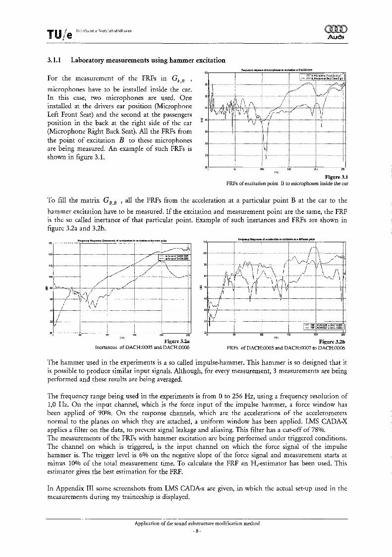
3.1.1 Laboratory measurements using hammer excitation
For the measurement of the FRFs in G k B '
microphones have to be installed inside the car. In this case, two microphones are used. One installed at the drivers ear position (Microphone Left Front Seat) and the second at the passengers position in the back at the right side of the car (Microphone Right Back Seat). All the FRFs from the point of excitation B to these microphones are being measured. An example of such FRFs is shown in figure 3.1.
Figure 3.1 FRFs of excitation point B to microphones inside the car
To fill the matrix GB,B ' all the FRFs from the acceleration at a particular point B at the car to the
hammer excitation have to be measured. If the excitation and measurement point are the same, the FRF is the so called inertance of that particular point. Example of such inertances and FRFs are shown in figure 3.2a and 3.2b.
Figure3.2b FRFs of DACH:0005 and DACH:0007 to DACH:0006
The hammer used in the experiments is a so called impulse-hammer. This hammer is so designed that it is possible to produce similar input signals. Although, for every measurement, 3 measurements are being performed and these results are being averaged.
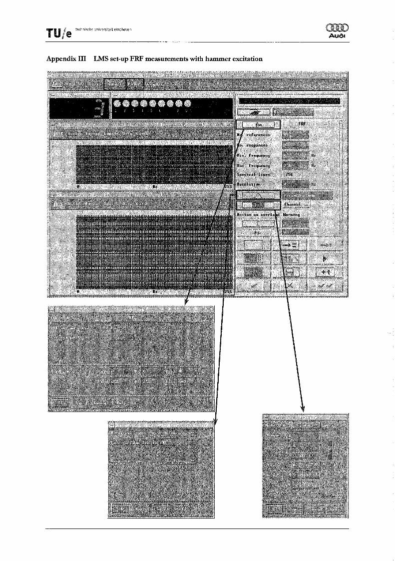
The frequency range being used in the experiments is from 0 to 256 Hz, using a frequency resolution of 1,0 Hz. On the input channel, which is the force input of the impulse hammer, a force window has been applied of 90%. On the response channels, which are the accelerations of the accelerometers normal to the planes on which they are attached, a uniform window has been applied. LMS CADA-X applies a filter on the data, to prevent signal leakage and aliasing. This filter has a cut-off of 78%. The measurements of the FRFs with hammer excitation are being performed under triggered conditions. The channel on which is triggered, is the input channel on which the force signal of the impulse hammer is. The trigger level is 6% on the negative slope of the force signal and measurement starts at minus 10% of the total measurement time. To calculate the FRF an Hv-estimator has been used. This estimator gives the best estimation for the FRF.
In Appendix III some screens hots from LMS CADA-x are given, in which the actual set-up used in the measurements during my traineeship is displayed.
Application of the sound substructure modification method
- 8-
T U kle red::11sche unive:rslteft eindhoven
"
3.2. Obtaining Pk,road and X B,road
O!ID Audl
Before the measuring of Pk,road and X B,road is being described, we take a closer look at equation (19).
All quantities in equation (19) have to be complex quantities. During the measurement of Gk Band
GB,B' these quantities become naturally complex. But, Pk,road and X B,road which are defined as
complex frequency spectra, are not naturally complex. Theoretically, it may be possible to measure
Pk,road and X B,road directly as complex frequency spectra, but in practice this is not possible because
to measure the exact input forces, in order to have the phase references. Under road conditions the exact input forces are not exactly known, and therefore difficult to measure. Therefore another method to
obtain Pk,road and X B,road as complex frequency spectra is applied. During the measurements on the
rollbench autopower spectra (APS) and frequency responses (FRF) are being measured. This results in the the following quantities:
APS{Pk,Road (m)} & APS{X B,Road (m)} (22 a & b)
and Frequency Responses to a particular reference, e.g. channel 1:
FRF] {Pk,Road (jm)} & FRF;. {X B,Road (jm)} (23 a & b)
The measured APS aren't complex, the measured FRFs are. Now it is possible to calculate the complex frequency spectra out of these measured quantities:
Amp = ..J2· APS
( . ) = A L (m)}x jPhase{FRF; (Pk,Road (jw»)} Pk,Road Jm mPLPk,Road e
X (.) - A {X ()}x jPhase{FRFj (XB,ROOd (jw»)} B,Road Jm - mp B,Road m e
Application of the sound substructure modification method
- 9-
(24)
(25)
(26)
T U Ie techoisch. ""ive"it~it ehdhoven mD Audl
3.2.1 Laboratory measurements using rolling road
When Pk,road and X B,road are measured using the rolling road, the car is placed with its rear wheels on
the rolls with rough asphalt (Appendix X). The rolls rotate at a speed of 30 km/h, because at this speed the booming noise is clearly present. By doing so, one obtains an input signal on the car, which can be considered to be equivalent to a random noise input. Although only the rear axis of the car is being driven, this is a good representation of reallife, road conditions.
To calculate the complex values of Pk,road and X B,road ,one has to measure both Auto Power Spectra
and FRFs, as she-wn in chapter 3.2. The Auto Power Spectra are measured as rms power spectra. If this isn't the case, formula (27) isn't correct, and must be adjusted.
The interior sound level is measured at two positions inside the car, at the front seat left (Microphone Left Front Seat) and at the back seat on the right side (Microphone Right Back Seat).
The references used during my traineeship are the 2 microphones (they are used as microphone, as well as a reference!) and the wheel hub rear axle right and left. Accelerations on the wheel hubs are measured
in +Z direction. All together 4 references. After calculating the new, complex values of Pk,road and
X B,road ' one can consider the influence of the choice of the reference on these new, complex
quantities. This will be discussed in the next chapter, Calculating modified interior sound levels .
The Auto Power Spectra of all the defined points (microphones, references and 'ordinary' points) have to be measured. In figure 3.3 the APS of two of the references, both wheel hubs of the rear axle, are displayed. The frequency response functions of all the 'ordinary' points with respect to all the references and the FRFs of all the references to each other have to be measured. It has to be noted that the FRFs can't be measured as MIMO FRFs. This is only possible if the chosen references are clearly not correlated. As shown in figure 3.3 the APS from these two references are, especially in the
.Auto Power Spectra R.el'erences 'Wheel swpeusion rear axlelelt and right
low frequency range, quite similar. The assumption that the signals are not correlated is false. An Hv-
estimator is used to calculate the FRFs. Because the FRFs have to be measured to all the references, one has to make sure that no measurements are forgotten. If the data set isn't complete, one won't be able to calculate all the desired interior sound levels. Also one must not forget to measure the FRFs from one reference to the other chosen references.
Application of the sound substructure modification method
-10 -
rUle tech:1ische universiteit eindhoven:
The frequency range used during the experiments on the rolling road, is the same as used before during the experiments with hammer excitation. So, it is from 0 to 256 Hertz, with a sample frequency of 1 Hertz. Measuring with a smaller frequency interval results in FRFs that become noisy. Greater frequency intervals aren't used, in order to prevent loosing crucial information. Because the car is on the rolling road, and its rolls are not exactly round, measurements are executed 30 times and averaged over these 30 measurements. The measurements have not been triggered. Although, it is possible to start the measurement on the same position of the rolling road every time. Uniform windows are applied on all channels. The acceleration data is measured in the direction normal to the surface on which the accelerometers are attached. Hanning windows are applied to both the references as well as the responses.
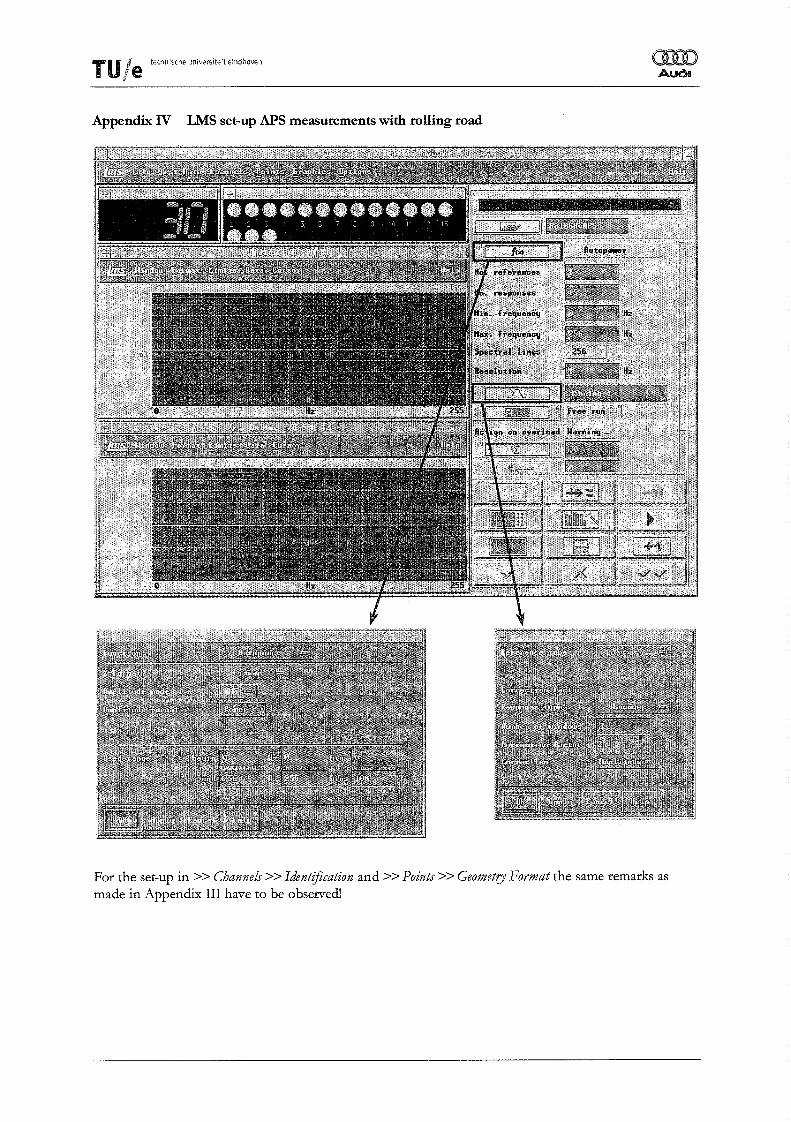
In Appendix N & V some screenshots from LMS CADA-x are given, in which the actual set-up used in the measurements is displayed.
Application of the sound substructure modification method
After all the data has been obtained in the measurements, it is possible to calculate the modified interior sound pressure levels, according to formula (19):
(Pk,road )new = Pk,road + Gk,B {H B,B (H B,B + H C,C )-1 H B,B - H B,B}X B,road (19)
Before the new sound pressure level (Pk,road ) new is calculated one has to evaluate the directions 1ll
which the measurements have been performed [3]. During the experiments using hammer excitation the direction of the applied force is opposite to the direction of the measured accelerations. Therefore the
matrices Gk,B' GB,B and H c,c have to be multiplied by -1. Formula (19) changes into formula (27).
The difference between those two formulae may be minor, but it is a crucial difference!
The calculation of the new interior sound pressure level (Pk,road )new has been programmed 1ll
MATLAB. For the exact description of this program an Instruction Manual has been written. For further details of the program, refer to this manual [7].
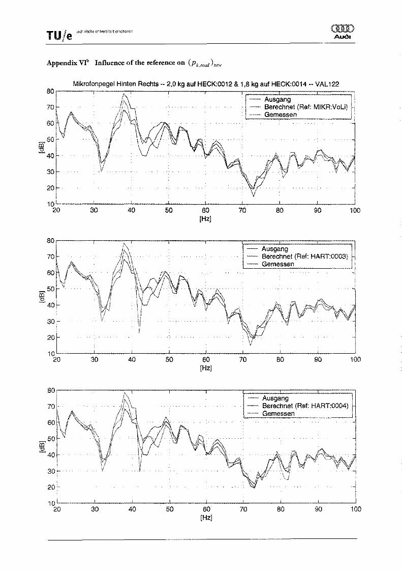
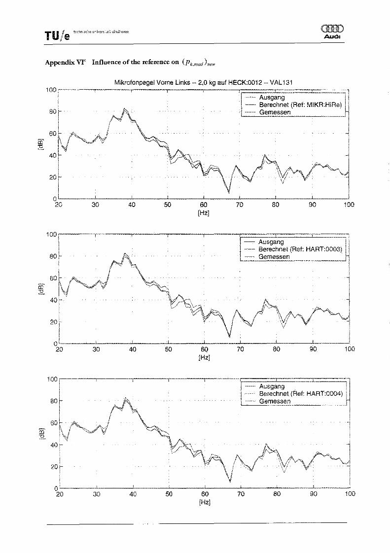
Now modified interior sound pressure levels can be calculated and considerations about the influence of the choice of the reference can be made. In Appendix VIa-d two mass modifications have been applied and the influence thereof on the interior sound level for both used microphones is calculated. Each calculation has been executed three times, and every time a different reference has been used, in order to
calculate the complex values of Pk,road and X B,road • It becomes clear, that the choice of the reference
has little influence of the calculated, new interior sound level. Therefore, for next calculations, the choice of the reference will be the other microphone. E.g. when calculating a modified sound pressure level on the left front seat, the reference will be the microphone on the right back seat. For calculating a modified sound pressure level on the right back seat, the reference will be the microphone on the left front seat.
Application of the sound substructure modification method - 12-
The calculation of modified interior sound pressure levels is now possible. But, which modification of the car has the greatest influence on the sound pressure level? And which points are sensitive for changes on the sound pressure level, when a mass is applied onto it? And what size should that mass be? Those questions can be answered if an optimisation tool is implemented, so a optimised mass application can be calculated, in order to achieve a optimised interior sound pressure level.
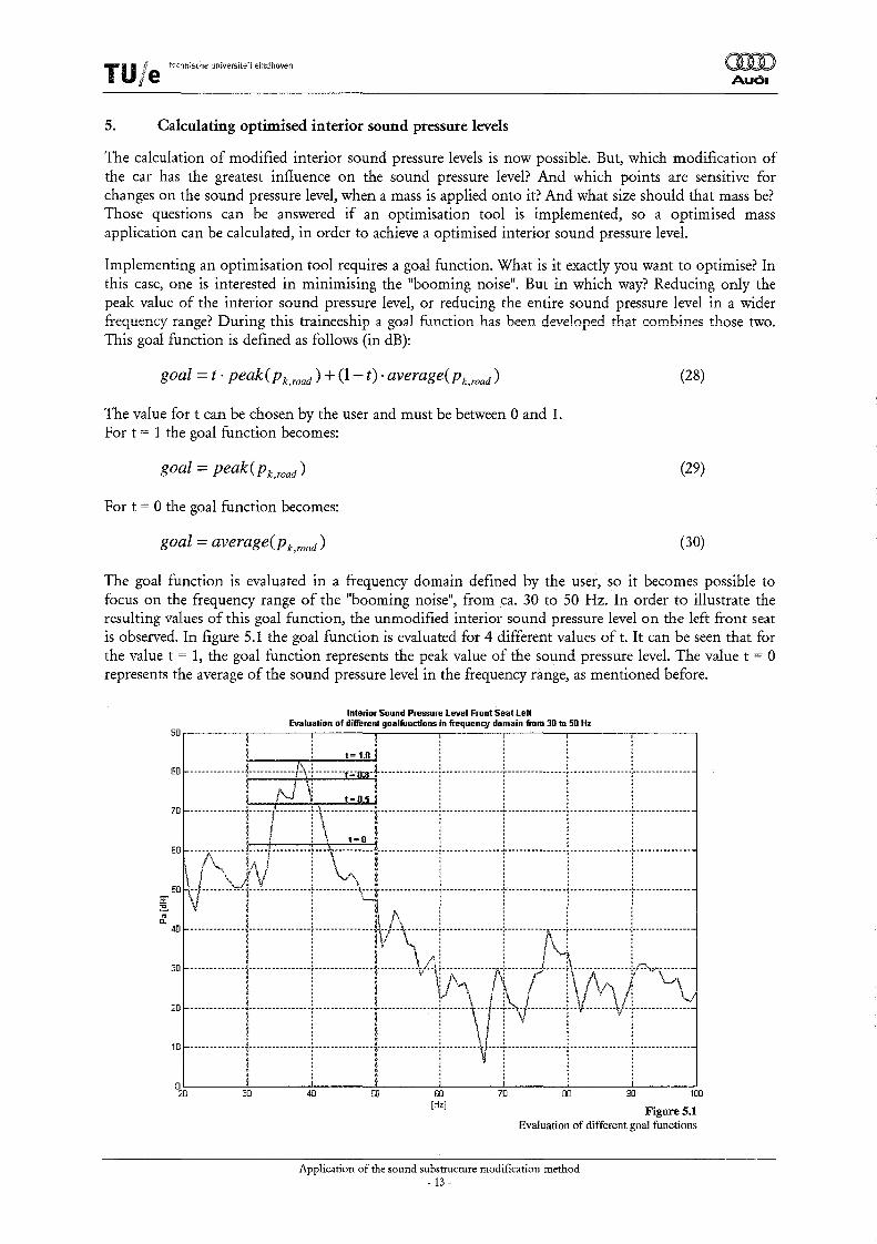
Implementing an optimisation tool requires a goal function. What is it exactly you want to optimise? In this case, one is interested in minimising the "booming noise". But in which way? Reducing only the peak value of the interior sound pressure level, or reducing the entire sound pressure level in a wider frequency range? During this traineeship a goal fi.,mction has been developed that combines those two. This goal function is defined as follows (in dB):
goal = t . peak(Pk,road) + (1- t)· average(Pk,road)
The value for t can be chosen by the user and must be between 0 and 1. For t = 1 the goal function becomes:
goal = peak(Pk,road)
For t = 0 the goal function becomes:
goal = average(Pk road)
(28)
(29)
(30)
The goal function is evaluated in a frequency domain defined by the user, so it becomes possible to focus on the frequency range of the "booming noise", from ca. 30 to 50 Hz. In order to illustrate the resulting values of this goal function, the unmodified interior sound pressure level on the left front seat is observed. In figure 5.1 the goal function is evaluated for 4 different values of t. It can be seen that for the value t = 1, the goal function represents the peak value of the sound pressure level. The value t = 0 represents the average of the sound pressure level in the frequency range, as mentioned before.
Interior Sound Pressure Level Front Seat Left Evaluation of different goalfunctions in frequenC!/ domain from 30 to 50 Hz
Application of the sound substructure modification method - 13-
T U if e technische universiteit eindhoven
"
With the goal function now known, an optImIsation routine can be implemented. Because the calculation of the modified interior sound pressure levels is already in MATLAB, the use of the optimisation toolbox in MATLAB is obvious. Before using the optimisation toolbox from MATLAB, one has to consider what kind of problem this is.
The problem of calculating the modified interior sound pressure level is of the following form:
minf(x) (31) x
In this case, x is the input for the calculation of the interior sound pressure level, the applied mass(es). f(x) is the calculated goal function, as described before. The only constraints that are active for this
problem is the minimal and maximal mass(es) that can be applied. The minimal mass is always 0 kg, which corresponds (of course) with no mass application at that particular point. The maximal mass can be defined by the user:
(32)
In the MATLAB optimisation toolbox a routine is available for this kind of problems: fmincon. m. This routine makes use of so-called constrained non-linear optimisation or non-linear programming. It is appropriate to find the minimum of a constrained non-linear multivariable function by starting at an initial estimate, and therefore suitable for this problem. In this case, a medium-scale algorithm is used, which uses so called Sequential ~adratic Programming (SQ!') to find a optimised solution to the problem. For exact information on this routine or the algorithm it uses refer to the MATLAB HELP Documentation [5] or Papalambros [6].
This optimisation has been programmed in MATLAB. For the exact description of this program an Instruction Manual [7] has been written. For further details of the use of the optimisation routine with respect to the calculation of optimised interior sound pressure levels, refer to this manual.
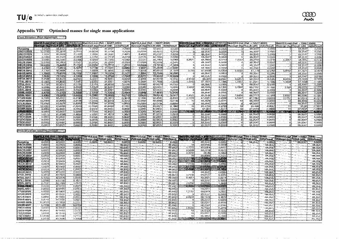
In order to determine which points are important in order to change the interior sound pressure level, for every point the mass has been calculated that results in the greatest change of the goal function (t =
1). Both the greatest positive as well as the greatest negative change in the goal function has been calculated. The results hereof are listed in Appendix VII'. Combinations of the most sensitive points are made, and the optimised mass combinations for those points are calculated. The results thereof are listed in Appendix VIIb. From these results it becomes clear that the use of different references has little influence on the calculated optimal masses. This is another argument for only using the reference of the 'other' microphone, as previously mentioned in chapter 4.
After calculation of the optimised masses for single mass applications (Appendix VI}'), it becomes clear that some points have great influence on the change of the interior sound pressure level. Although, some other points have no influence on the change of the interior sound pressure level at all. Noticeable is that of the points that have great influence on the interior sound pressure level on the left front seat, 4 of them are on the tail door (HECK:OOlO, HECK:OOll, HECK:0013 and HECK:0014). The points on the left side windows have also great influence (SSML:0020 and SSHL:0021). The point on the right rear side window (SSHR:0027) is very sensitive to change the interior sound pressure level on the back seat right.
Application of the sound substructure modification method - 14-
rUle tech~ische uni'ilersit-eit eindhoven
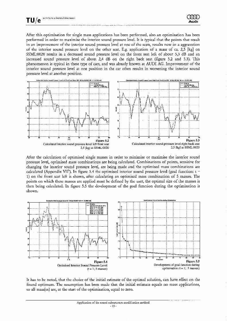
After this optimisation for single mass applications has been performed, also an optimisation has been performed in order to maximise the interior sound pressure level. It is typical that the points that result in an improvement of the interior sound pressure level at one of the seats, results now in a aggravation of the interior sound pressure level on the other seat. E.g. application of a mass of ca. 2,5 [kg] on SSML:0020 results in a decreased sound pressure level on the front seat left of about 5,3 dB and an increased sound pressure level of about 2,4 dB on the right back seat (figure 5.2 and 5.3). This phenomenon is typical in these type of cars, and was already known at ADDI AG. Improvement of the interior sound pressure level at one position in the car often results in worsening the interior sound pressure level at another position.
Calculated interior sound pressure level right back seat 2,5 [kg] at SSML:0020
After the calculation of optimised single masses in order to minimise or maximise the interior sound pressure level, optimised mass combinations are being calculated. Combinations of points, sensitive for changing the interior sound pressure level, are being made and the optimised mass combinations are calculated (Appendix VIIb
). In figure 5.4 the optimised interior sound pressure level (goal function: t =
1) on the front seat left is shown, after calculating an optimised mass combination of 5 masses. The points on which these masses are applied must be defined by the user, the optimal size of the masses is then being calculated. In figure 5.5 the development of the goal function during the optimisation is shown.
Optimierte lillkrofonpegellGoal po.so Hz): 82.1U31 dB .... > 78.3666 dB]
It has to be noted, that the choice of the initial estimate of the optimal solution, can have effect on the found optimum. The assumption has been made that the initial estimate equals no mass applications, so all mass(es) are, at the start of the optimisation, equal to zero.
Application of the sound substructure modification method - 15-
TU Ie tech,ische "nivers;t~it eindhoven
,
6. Validation of calculated modified interior sound pressure levels
Now it is possible to calculate modified and optimised interior sound pressure levels, it has to be considered if those calculations are correct. In the past the sound substructure modification method has been used at AUDI AG, and it was proved that the method delivers correct results. However, in the past the measurements where performed using shaker excitation ([1] & [2]) or real life road conditions [3]. Using shaker excitation, it is possible to perform measurements that can be easily repeated and reproduced. For measurements under real life conditions it is very hard to get reproducible measurements. During this trainees hip the measurements under road conditions where performed using a rolling road.
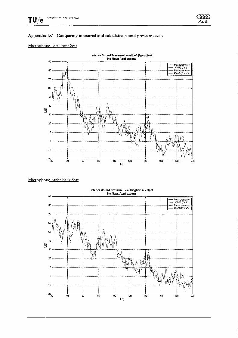
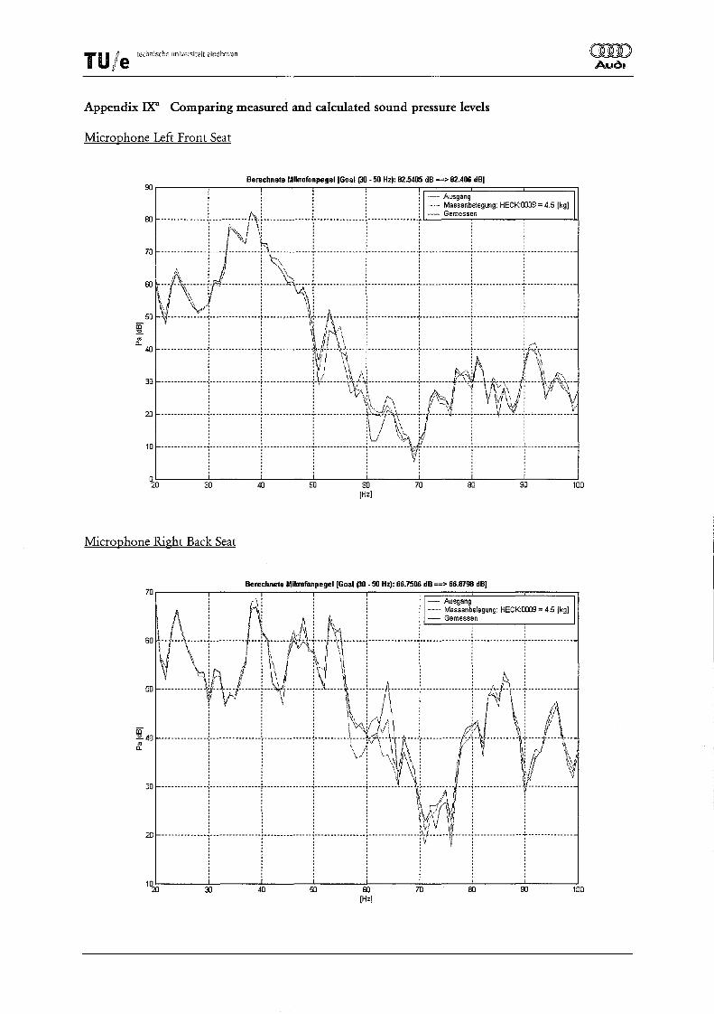
It now has to be considered how the reproducibility of those measurements is. Because the validation measurements are executed about 3 weeks later, on the same car, it is of great importance that the reproducibility of the measurements is quite good. In figure 6.1 and 6.2 (Appendix IXa
) the interior sound pressure levels of the two used microphones are displayed, when no mass modifications on the car are applied. It becomes evident that between two measurements, performed on the same physical set-up, a certain difference in the Interior Sound Pressure Level Left Front Seat
sound pressure levels is present, 90 No Mass Applications
;~~~~r i~i~~~::~~s B~:t!~:~ :~: 80 -----------,! -------------;--------------l-------------+-------------;--------------l--------------~-----I--- E:~4S~~: initial measurements and the 70 --------~~-------------L----------L-----------L----------L-----------l--------------l------=-T~-~-~:-~--~~~:~ me::~:em~~~s. O~~~;e~e:: 80 lk-A----l-\\---------1--------------f--------------l--------------1-----------------------------f-------------,-------------manifests mostly above 80 Hz, 80 ~--'~JI----t--Y:*-k\---j--------------t-------------t-------------i-------------+------------t-------------i-------------on the back seat right the ffi' 40 ------------+------\t\\-+----------d:------I~\---+------------+-----------+------------+-------------+------------
:~re~e i:.:~~h g<;tcr~~:; ~.jtM~t~+k++ :::so~:~ I~e~h: t~:~ b~:ee:t~~; 20 ------------(-----------1i:>\\1:1t--t1-1)-------'nll;t~;l----i~(\At~~----~-----r------------j-------------analyses, and some changes 10 -----------+------------1----\ l------t-------------+--":~-r.~~,~~rl HfIJ-- - '\----r-------------.:,"---. ---------
j l l j Y, i~Q\{~ j Jl~ \,'1 i l (:~,~., iT,!" ~{\ have been made to the car. The -------------:--------------j--------------t--------------:--------------i-¥!~--j-----!--------- :----~---rf,\t~- Ir-F----gear box has been replaced. The iii i i ~v i \\~ i't!/ ~;i,~ <I '\ A I new gear box has the same mass -10 -------------I--------------j--------------t-------------t-------------j---- .. --------(--------~\:,,.-------j-'i-~-\}~ as the old one. Also some -2~ 40 60 80 100 120 140 180 180 200
changes have been made to the [Hz] Figure 6.1
compressor of the climate Interior Sound Pressure Level Right Back Seat
control. The influence thereof 90 No Mass Applications
on the interior sound pressure level is not known. Another reason could be the way the car stands on the rolling road. A little difference in the way it stands on the rolls, can cause a difference in the measured sound pressure level. The air pressure in the tires during both measurements was 2,4 bar. Another possible explanation for the difference between the sound pressure levels could be the contents of the fuel tank.
: : : i : : '¥i!\-'il~H L~ I {\~' -10 ------------"I"-------------j--------------t-------------t-------------j--------------t------------\l-r---~:!-~----or i(\q~i/
-20
20 40 80 80 100 120 140 1&l 180 200 [Hz]
Figure 6.2
Application of the sound substructure modification method -16 -
TU Ie techn;sche unive,s;teit eindhoven
Because the differences between the 'old' and 'new' interior sound pressure levels with no mass applications can't be explicitly cleared, it is assumed that the 'new' interior sound pressure level is the correct one. For further calculations and validations those new sound pressure levels will be used. In this way, the comparison of the calculated and measured sound pressure levels is the most fairest. If the validation is compared with the initial calculation (Figure 6.3) the comparison between validation and calculation seems very poor. This is due to the difference between the 'old' initial sound pressure level and the 'new' initial sound pressure leveL In figure 6.4 the calculated sound pressure level is calculated using the 'new' interior sound pressure level, and the comparison is now better.
Figure 6.4 Comparing calculated and measured interior sound pressure level
using 'new' initial measurement
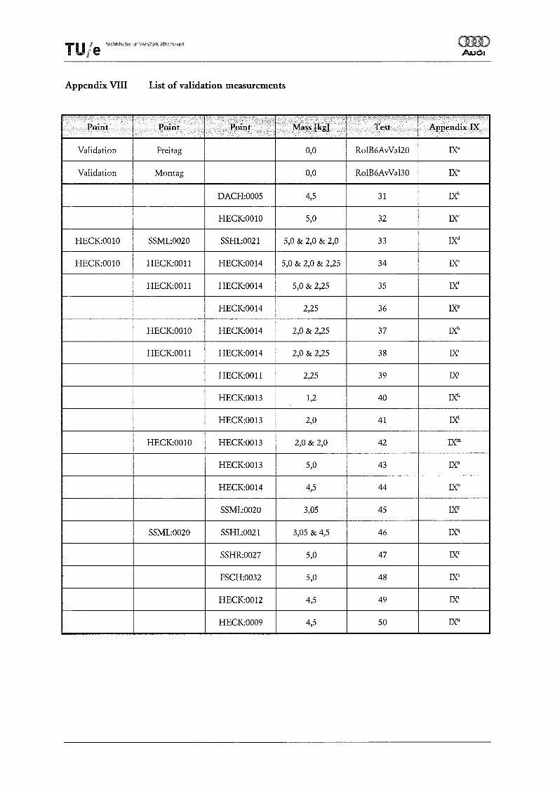
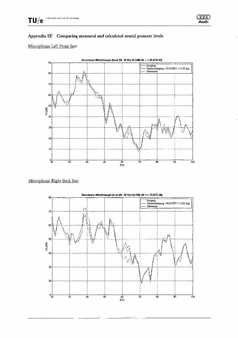
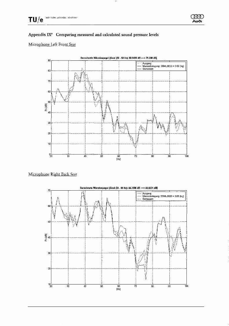
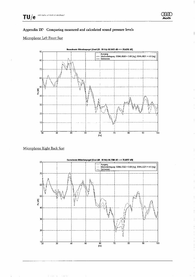
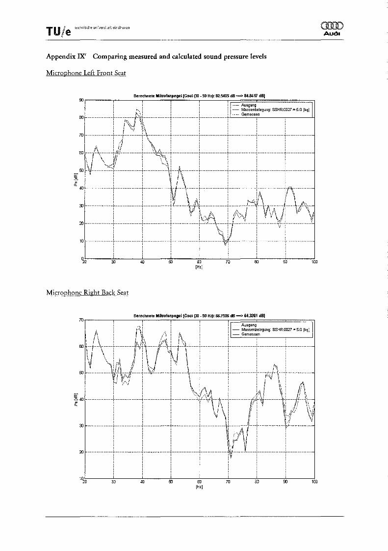
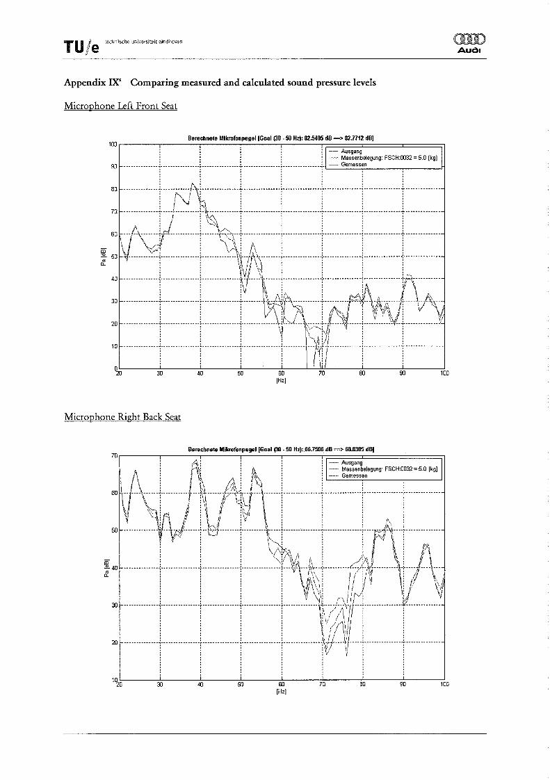
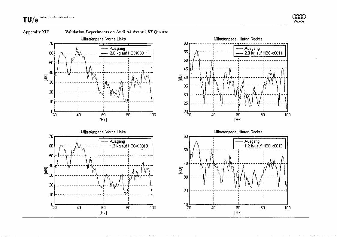
With use of the optimisation tool the sensitivity of all points has been evaluated. Also some combinations of sensitive points are optimised. The results hereof are used to validate the calculated interior sound pressure levels. Twenty different masses or mass combinations are being put on the car, and the interior sound pressure level at the two used microphones is being measured. The car is on the rolling road, under the same conditions as described in chapter 3. In Appendix VIII the different masses or mass combinations used in the validation measurements are listed. In Appendix IX all the measured and calculated interior sound pressure levels are presented in graphics.
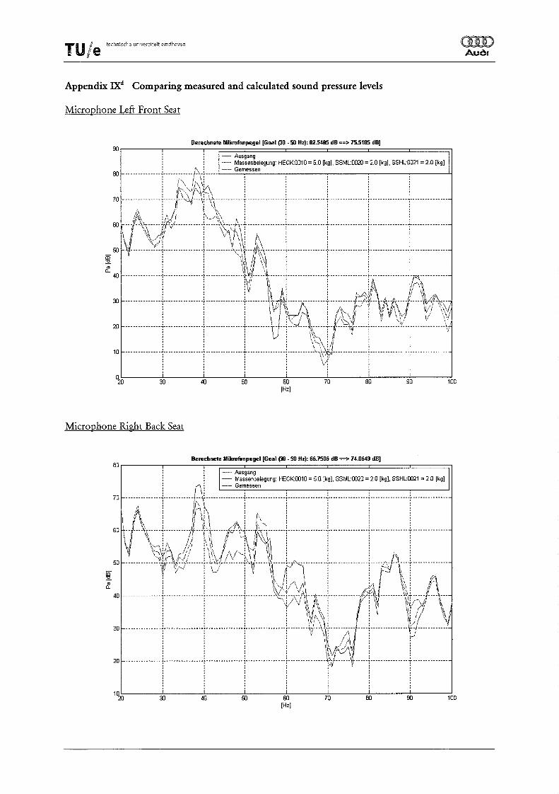
As can be seen in the results, the method is able to predict the modified interior sound pressure levels. E.g. in figure 6.5 and 6.6 (Appendix IXd and JX'l) both calculated as well as the measured modified interior sound pressure levels on the front seat left are presented. For the combined mass application of 5,0 kg at HECK:0010, 2,0 kg at SSML:0020 and 2,0 kg at SSHL:0021 the calculated sound pressure level reduces in peak value with 7,0 dB. Measured is a reduction of about 5,6 dB (Figure 6.5, App. IXd
). For the combined mass application of 3,05 kg at SSML:0020 and 4,5 kg at SSHL:0021 a reduction of 4,1 dB is calculated and a reduction of 5,3 dB is measured (Figure 6.6, App. IX'!).
oo __ ---:--~·'~mm='~~~.~~~~~g'~I~~~~I~~.~~~H~~'~~~~~=-=>~~='~~~~====c===~ I AusgaQg
Calculated and measured sound pressure level left front seat 3,05 kg at SSML:0020 and 4,5 kg at SSHL:002l
Application of the sound substructure modification method - 17 -
T U I techn:lsche LmiversitE-it eindhoven
be
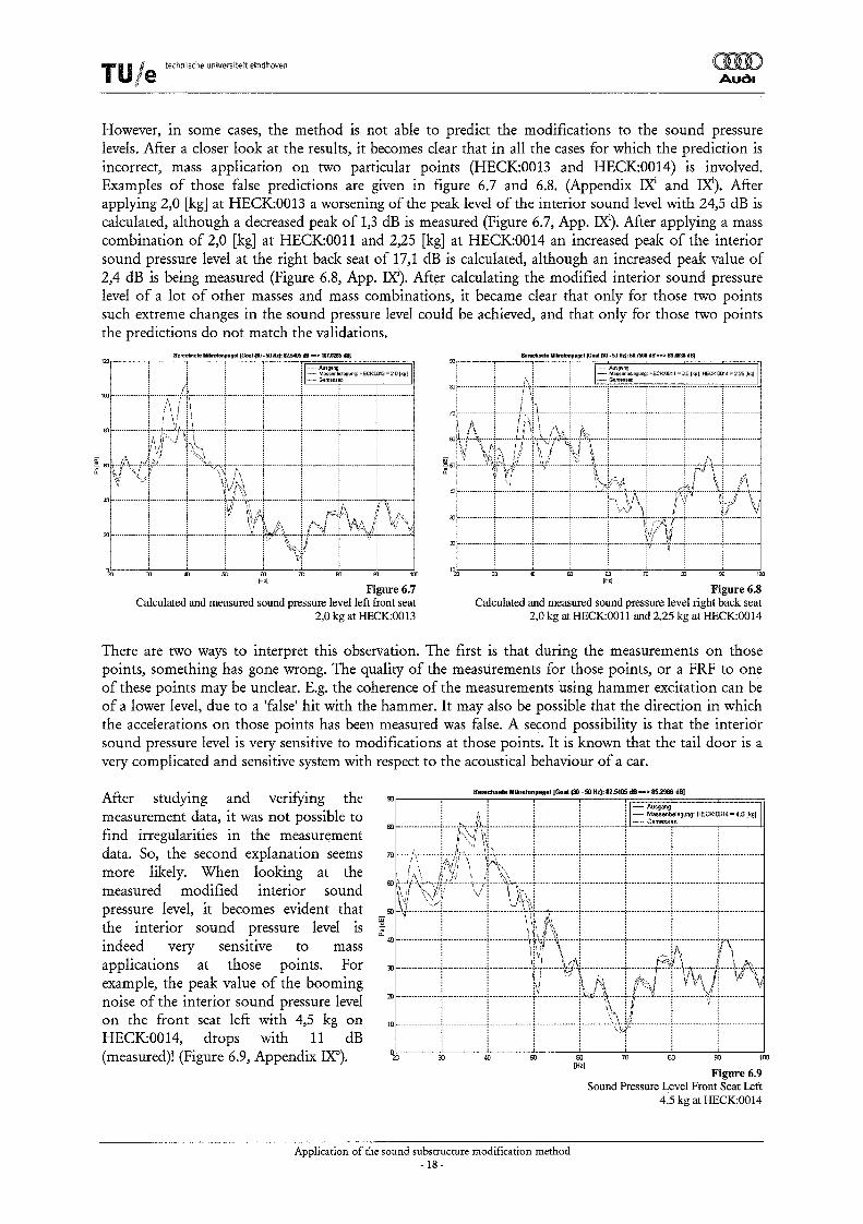
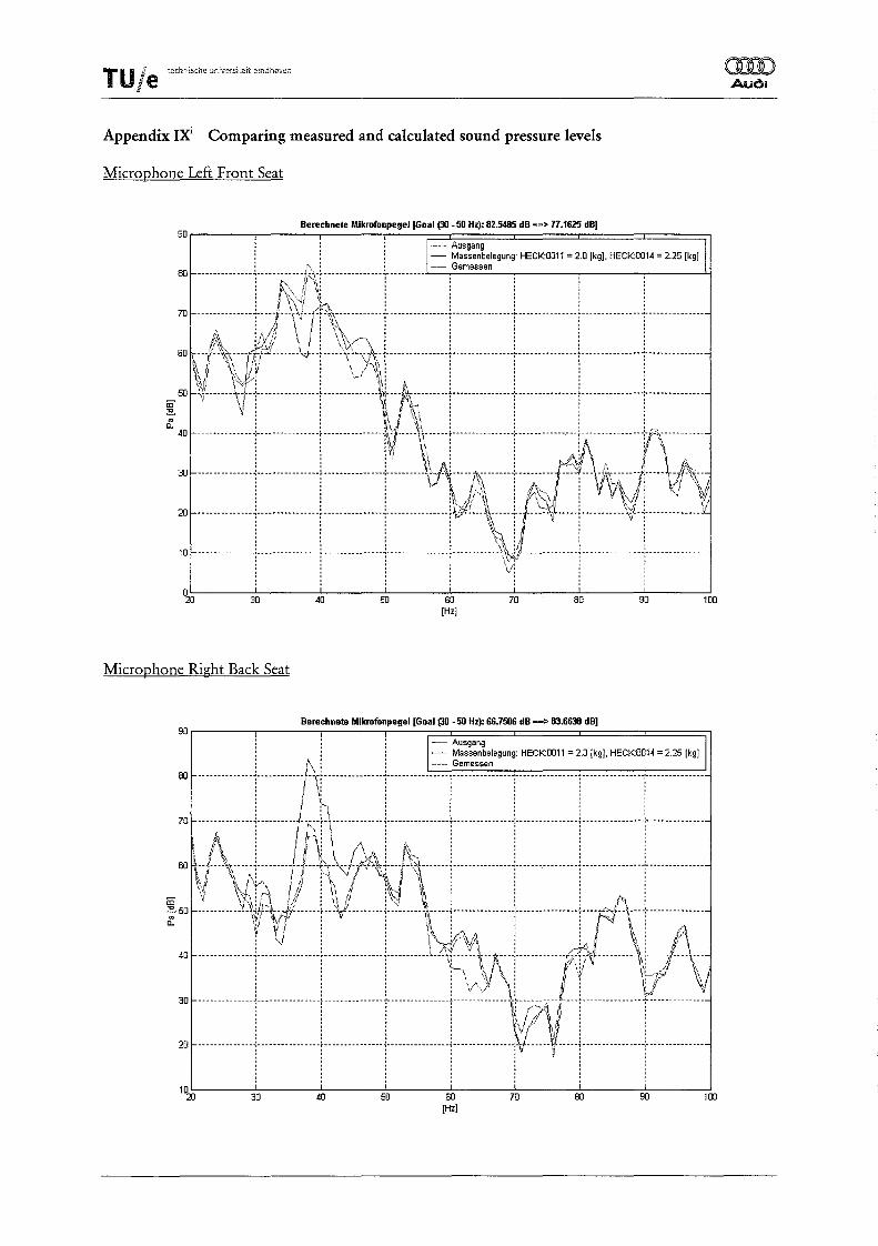
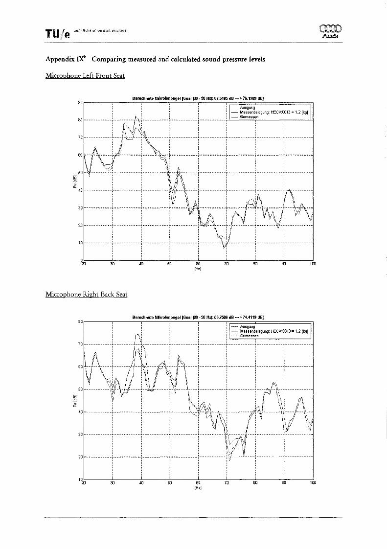
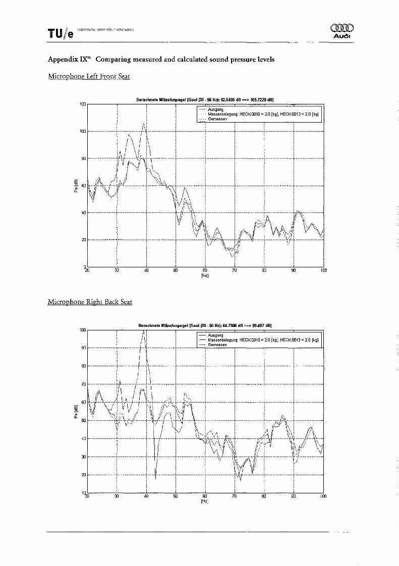
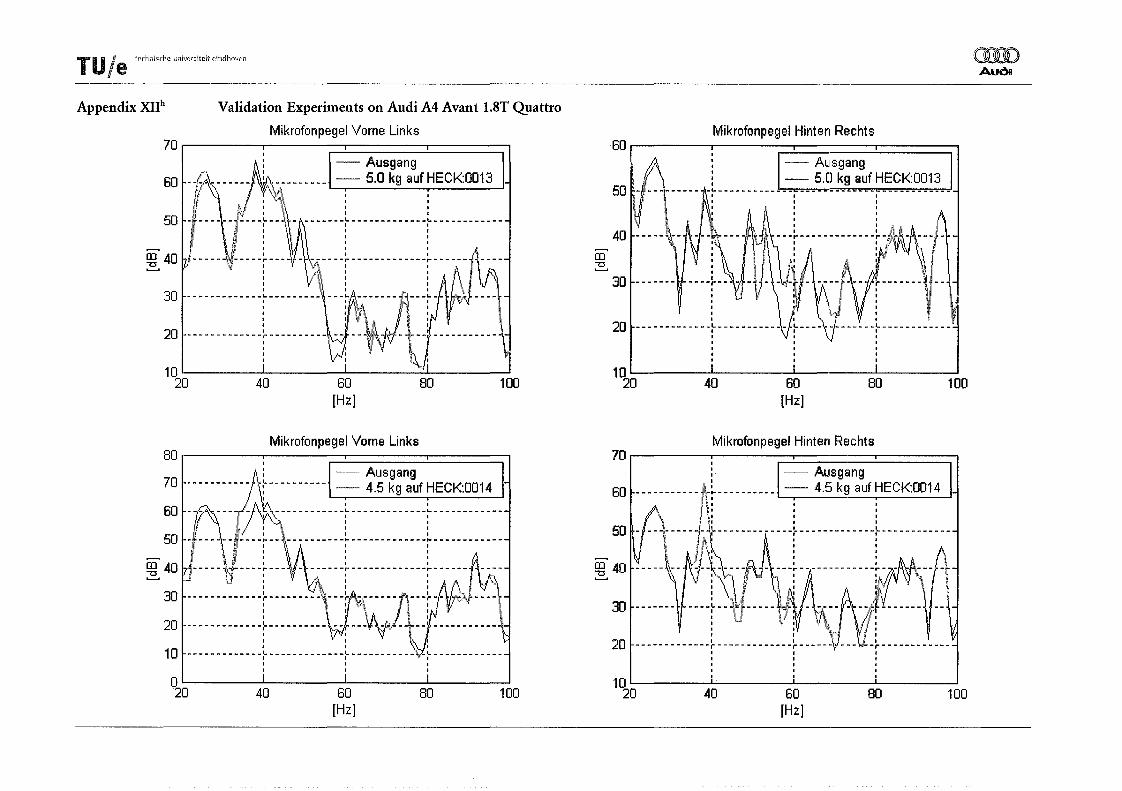
However, in some cases, the method is not able to predict the modifications to the sound pressure levels. After a closer look at the results, it becomes clear that in all the cases for which the prediction is incorrect, mass application on two particular points (HECK:0013 and HECK:0014) is involved. Examples of those false predictions are given in figure 6.7 and 6.8. (Appendix IXi and IXI). After applying 2,0 [kg] at HECK:0013 a worsening of the peak level of the interior sound level with 24,5 dB is calculated, although a decreased peak of 1,3 dB is measured (Figure 6.7, App. IXI). After applying a mass combination of 2,0 [kg] at HECK:0011 and 2,25 [kg] at HECK:0014 an increased peak of the interior sound pressure level at the right back seat of 17,1 dB is calculated, although an increased peak value of 2,4 dB is being measured (Figure 6.8, App. IXi). After calculating the modified interior sound pressure level of a lot of other masses and mass combinations, it became clear that only for those two points such extreme changes in the sound pressure level could be achieved, and that only for those two points the predictions do not match the validations.
1~r-__ -: ___ B' __ :'~ __ .I-~MPr··~·II~G'~"~~~_~~'~~~dB=->71O~'~~~======~
Figure 6.8 Calculated and measured sound pressure level right back seat
2,0 kg at HECK:OOll and 2,25 kg at HECK:0014
There are two ways to interpret this observation. The first is that during the measurements on those points, something has gone wrong. The quality of the measurements for those points, or a FRF to one of these points may be unclear. E.g. the coherence of the measurements using hammer excitation can be of a lower level, due to a 'false' hit with the hammer. It may also be possible that the direction in which the accelerations on those points has been measured was false. A second possibility is that the interior sound pressure level is very sensitive to modifications at those points. It is known that the tail door is a very complicated and sensitive system with respect to the acoustical behaviour of a car.
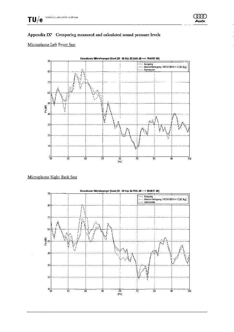
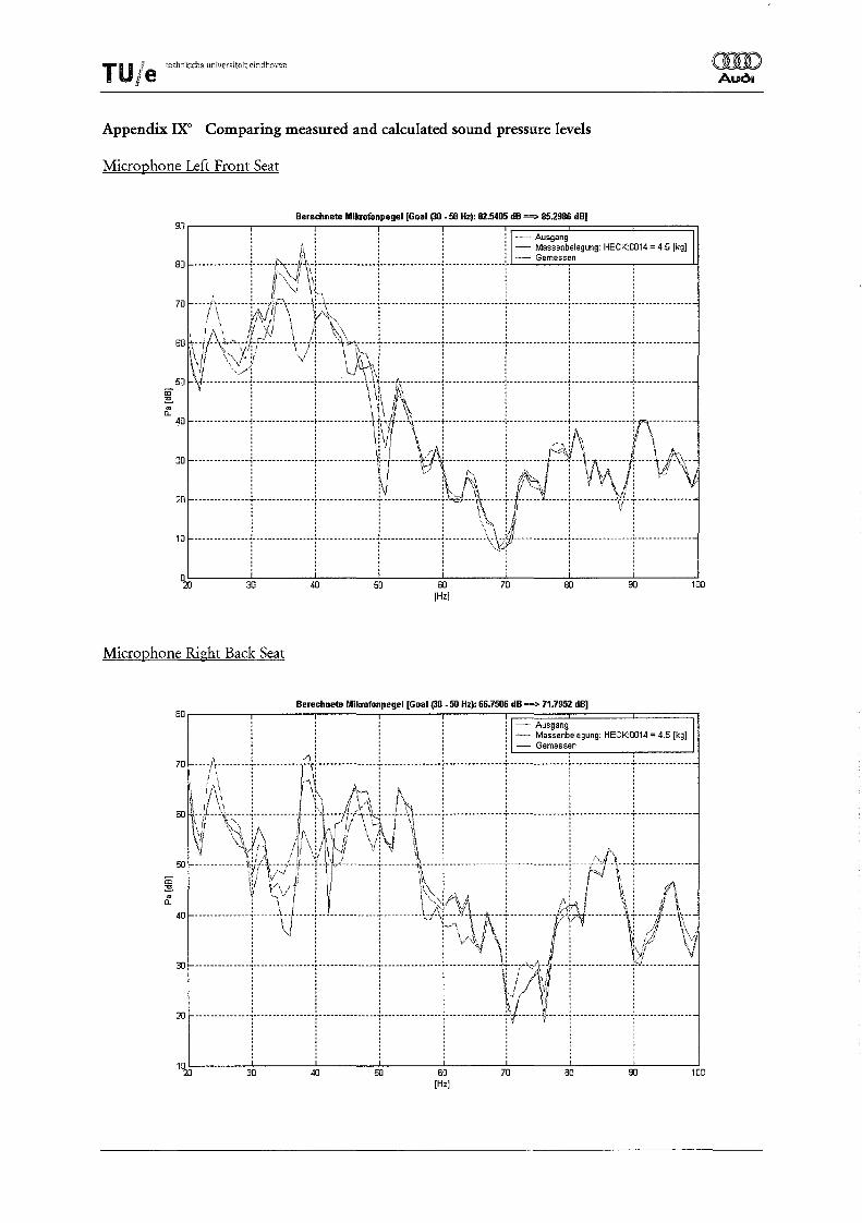
After studying and verifYing the measurement data, it was not possible to find irregularities in the measurement data. So, the second explanation seems more likely. When looking at the measured modified interior sound pressure level, it becomes evident that the interior sound pressure level is indeed very sensitive to mass applications at those points. For example, the peak value of the booming noise of the interior sound pressure level on the front seat left with 4,5 kg on HECK:0014, drops with 11 dB (measured)! (Figure 6.9, Appendix IXO).
Application of the sound substructure modification method - 18-
T U Ie tech:--l)sche Lmjversireit eindhoven
" 7. Conclusions
(1ID Audl
After finishing the measurements, calculating modified interior sound pressure levels and validating them, it became clear that the sound substructure modification method is able to predict the modifications in the interior sound pressure level due to mass applications on the car. This was already proved in the past, but not in combination with the use of the rolling road.
The whole procedure, from the measurements until the validation of the calculated sound pressure levels, has passed and is described in this report and an Instruction Manual [7]. So, the sound substructure modification method is now a applicable tool at AUDI AG, and can be used more easily in the future.
An optimisation tool has been implemented in MATLAB, so it is now possible to calculate optimised mass or mass combinations in order to minimise the booming noise. The optimisation tool is also very useful for checking which points of the car are sensitive for changing the interior sound pressure level.
Application of the sound substructure modification method - 19-
T U Ie te<:hnische unwersiteit eindhoven
•
References
omD Audl
[1] E. Debeaux and M. Claessens (AUDI AG, Ingolstadt) and X. Hu (EDAG AG, Ingolstadt) (2000), An ana(ytical-experimental method for analYsing the lowfrequenty interior acoustics if a passenger car, Proceedings ISMA 25, Leuven
[2] X. Hu (1997), TidJrequente Karosseriedrohnen von FahrzeugA4 Limousine, Research Report, AUDI AG, Ingolstadt
[3] X. Hu (1999), Methodenentwicklung zur Verbesserung des tidJrequenten Drohnens am Audi A6 Limousine, Technical Report, EDAG AG, Ingolstadt
[4] J. Frappier and]. Bukovics (AUDI AG, Ingolstadt) (1999), Influence ifbot(y-vibrations to lowfrequenty boom interior noise. physical dJects and improvements, Aachener Kolloquium Fahrzeug- und Motorentechnik 1999, Aachen
[5] MATLAB HELP Documentation, MATLAB Version 6.1.0.450, Release 12.1
[6] P.Y. Papalambros and D.]. Wilde (2000), Principles if Optimal Design, modelling and computation, Cambridge
[7] AAA Peeters (2001), Instruction Manual· Using the sound substructure method in MATLAB I AUDI AG, Ingolstadt
Application of the sound substructure modification method
- 20-
TU Ie technische universit€it eindhoven
Appendix I
Car:
Car #: Number Plate: Engine: Drive:
Technical Specifications of Audi A4 Avant (711-307, IN-W-4613)
Audi A4 Avant
711-307 IN-W-4613
Changing Gears:
3,0 L V6 (162 kW) Front Wheel Drive Manual B80 5-speed Left Steering Wheel:
Tires:
Configuration:
Michelin 215/55 Radial R16 XSE (2,4 bar)
Sliding Roof Cloth Panelling
([D) Auol
T U Ie ,.choisch. univers!,eit eindhoven
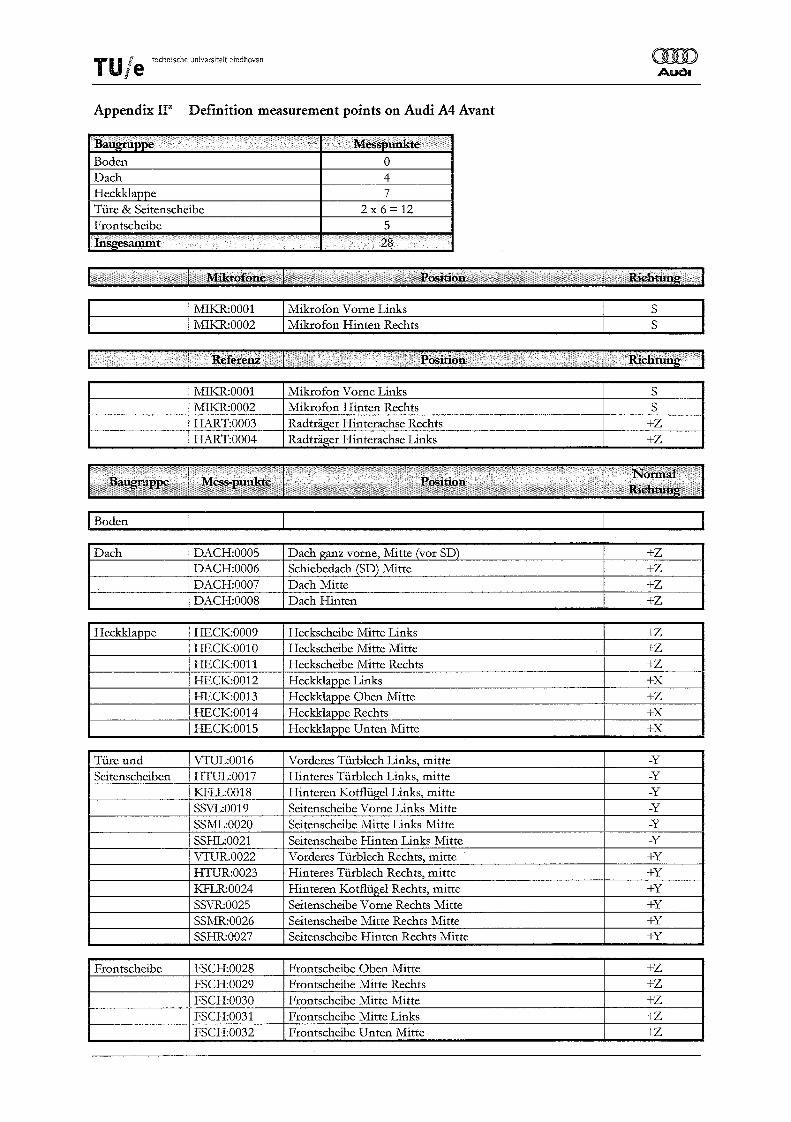
Appendix na Definition measurement points on Audi A4 Avant
MIKR:0001 Mikrofon Vorne Links S MIKR:0002 Mikrofon Hinten Rechts S
q ........... . t ·~clituDg
MIKR:0001 Mikrofon Vorne Links S MIKR:0002 Mikrofon Hinten Rechts S HART:0003 Radtrager Hinterachse Rechts +Z HART:0004 Radtrager Hinterachse Links +Z
I Boden
Dach DACH:0005 Dach ganz vorne, Mitte (vor SD) +Z DACH:0006 Schiebedach (SD) Mitte +Z DACH:0007 Dach Mitte +Z DACH:0008 DachHinten +Z
Heckklappe HECK:0009 Heckscheibe Mitte Links +Z HECK:0010 Heckscheibe Mitte Mitte +Z HECK:0011 Heckscheibe Mitte Rechts +Z HECK:0012 Heckklappe Links +x HECK:0013 Heckklappe Oben Mitte +Z HECK:0014 Heckklappe Rechts +x HECK:0015 Heckklappe Unten Mitte +x
Tiire und VTUL:0016 Vorderes Tiirblech Links, mitte -y Seitenscheiben HTUL:0017 Hinteres Tiirblech Links, mitte -y
KFIL:0018 Hinteren Kotfliigel Links, mitte -y SSVL:0019 Seitenscheibe Vorne Links Mi tte -y SSML:0020 Seitenscheibe Mitte Links Mitte -y SSHL:0021 Seitenscheibe Hinten Links Mitte -y VTUR.OO22 Vorderes Tiirblech Rechts, mitte +y HTUR:0023 Hinteres Tiirblech Rechts, mitte +y KFLR:0024 Hinteren Kotfliigel Rechts, mitte +y
SSVR:0025 Seitenscheibe Vome Rechts Mitte +y SSMR:0026 Seitenscheibe Mitte Rechts Mitte +y SSHR:0027 Seitenscheibe Hinten Rechts Mitte +y
Frontscheibe FSCH:0028 Frontscheibe Oben Mitte +Z FSCH:0029 Frontscheibe Mitte Rechts +Z FSCH:0030 Frontscheibe Mitte Mitte +Z FSCH:0031 Frontscheibe Mitte Links +Z FSCH:0032 Frontscheibe Unten Mitte +Z
TU/e tecnnlsche uniVCfsitp.ii" eindhoven
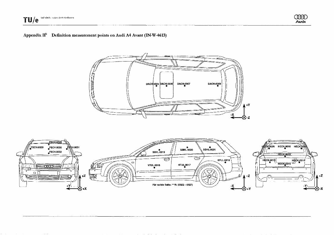
Appendix lIb Definition measurement points on Audi A4 Avant (IN-W-4613)
DACH 0005 ACH:0006 DACH:0007 III III III
VTUL:0016 III
FOr rechte Seite: '''R: (0022 - 0027)
DACH:0008 1/1
HECK:0010 III
rUle tethnische universitcft eindhoven (]II) Auol
Appendix III lMS set-up FRF measurements with hammer excitation
The reference channel for the estimation of the FRF (in this case the hammer), must always be on top of the list of available channels!
» Points» Geometry Format:
The input of the Node Names (Comp), the Node Numbers (Node) and their Directions (Dir) must exactly match the names, numbers and codes you defined in the list. (Appendix Ie)!! This in order to prevent problems with the calculation in MA1LAB later.
TU I techndsche l..mi'Jersiteit eindhoven j,e
i
Appendix IV IMS set-up APS measurements with rolling road
For the set-up in » Channels» Identification and » Points» Geometry Format the same remarks as made in Appendix III have to be observed!
T U j e technlsche universitett eindhoven
1/
Appendix V lMS set-up FRF measurements with rolling road
oorro Auol
For the set-up in » Channels » Identification and » Points » Geometry Format the same remarks as made in Appendix III have to be observed!
TU Ie technische uTIiversiteit eindhoven mJ) Auda
Appendix vr Influence of the reference on (Pk,road) new
Mikrofonpegel Vorne Links - 2,0 kg auf HECK:0012 & 1,8 kg auf HECK:0014 -- VAL 121 100r--------r----------.--------.---------.-------___ ~=====c======~====~
40
30 40 50 60 [Hz]
70
- Ausgang I - Berechnet (Ref: MIKR:HiRe) ~ Gemessen
m ,- ---\k-j/-·rrJ~.-f\\-·--·i···········-··i·········-·-l-·--.~ ... -~.-.. --.--.-.. m 50 -----------~~r-\t:JL----t-Jllb-L .. ::---f\\r---\ ----J/'~l"~---------i----------------l----,t:y-\--f-------~----:;- • I • Il / ' 'f' ~k~~
D- 40 --------------i----------------f---------------i----------\Zj)y\ -}~:---i------------- /~~I--------- :tii-;::/---\--1 1 1 r 'U \~l 1 IV 111 1"/" \1, , , , , "f)'" \ . , I' . V
30 -------------+---------------r---------------i·---------------j--------~i-\ i-------)i-- ----j---------------r/----------: , I , I \, I I I , ; ; ; ; \! /1'\; ;
m 50 \f------:~-+--------------f-------~:-'~~~1M:---~~~---------!----------------i----------------i----------------:---------------.., , , \~, I \\' , , , ';; i : I'i ! I.: i : :
II \~\ iiI) \~~\ i f'." iii i 60 J~ ---\\~-!-'~------1- -:r---i\ --- /' -'\~~--1-1~~.-------i----------------i----------------i----------------:---------------
_ ..f \\"" iA . j' i \\ i : \"1' iii i ~ 50 -~--------~L·W:!'~iT;c.----r--:':·;2(\--r_1i~{--\\\::-).----------- -----:----------------l---r-rf\----:--------~--.-----
,OO-----+--An----l-------T----------t-=-G:~:-'T----T-----: h l \.: : : : : :
: iN.: : : : :
80[ .............. LJ ..... VI~.l.t···········L ............. L. ............ .i.. ............. .L ............. L ........... . Y:\l"C}"\~~ i i ! i i
f I /,< : ~~,,: : : : :
~ 60 ~,: /\\;Vf~/.··········t····~ \~\{-~;---!------t------i----)----V 'i i iV.; \\\ i i ! i
~ -------------j---------------!-------------v-:~~------ -----1f4-----=-\-----T\1\ 20 .............. 1 ................ l ............... J .......... V .... f\:f~ ...... l .. .... :: ....... l .... ~YVJ. ...... '.< .... ~
'w-+j--\--tl--+-------l ----r------ l ---------80 --------------if\--,~,-~j?\J-~'-----------+--------------\----------------I----------------I---------------r-------------
·············-i-· .. ············t···············i··· .. ···········j······-········+r-···V ..... j ................ : .............. . i i : i i ~ i i
30 40 50 60 [Hz]
70 80 90 100
TU /e techniscMe "oiversi!e;t eindhoven
Appendix IX' Comparing measured and calculated sound pressure levels
20 --------------~----------------f---------------~----------------~''i~l!/'J'~··\-,-----i-,- -----\-----!------- '---:' ---i--------------~, iii 1 \ iii
Time data of all channels (useless due to averaging the time data) APS data of all channels FRF data of all points with respect to MIKR:OOOI FRF data of all points with respect to MIKR:0002 FRF data of all points with respect to HART:0003 FRF data of all points with respect to HART:0004 So-called cross FRFs of the references to each other. Validation Experiments. (20 and 30 are the new initial measurements, 31 -50 are the validation experiments as listed in Appendix VIII) Same validation experiments as in 20/30-50, but now on Audi A4 Avant, 1.8T QIattro (721-253) Measurements used in order to find the correct setup. backup test, with the standard setup used during the measurements
All data of experiments using hammer excitation
Measurement data of experiments using hammer excitation (b6avemph ==> EmpB6Avl) FRF data of experiments using hammer excitation (b6avemph ==> EmpB6Avl) APS data of experiments using rolling road (b6avrm ==> Ro1B6AvAPS) FRF data of experiments using rolling road (b6avrm ==> Ro1B6AvIFRF, Ro1B6Av2FRF, Ro1B6Av3FRF, Ro1B6Av4FRF and Ro1B6Av4FRFxx) 'new' initial measurements (b6avrm ==> Ro1B6AvVal20 and Ro1B6AvVa130) Validation measurements (b6avrm ==> Ro1B6AvVal20 - 50) Validation measurements A4 Avant, 1.8T QIattro (b6avrm ==> Ro1B6AvVall20 - 150)
TU Ie teCh";sc"e "niversiteit .indhoven OOD Audl
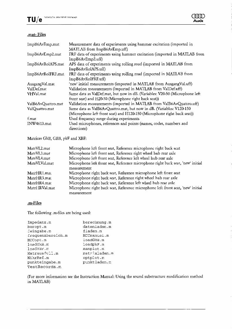
.mat- Files
ImpB6AvEmp.mat
ImpB6AvEmp2.mat
ImpB6AvRolAPS.mat
ImpB6AvRo1FRF.mat
AusgangVal.mat ValDef.mat VHVal.mat
VaIB6A~attro.mat
Val~attro.mat
Emat INW4613.mat
Measurement data of experiments using hammer excitation (imported in MATLAB from ImpB6AvEmp.uff) FRF data of experiments using hammer excitation (imported in MATLAB from ImpB6AvEmp2.uff) APS data of experiments using rolling road (imported in MATIAB from ImpB6AvRoIAPS.uff) FRF data of experiments using rolling road (imported in MATIAB from ImpB6AvRoIFRF.uff) 'new' initial measurements (imported in MATLAB from AusgangVal.uff) Validation measurements (imported in MATLAB from ValDeEuff) Same data as ValDef.mat, but now in dB. (Variables: V20-S0 (Microphone left front seat) and H2O-SO (Microphone right back seat» Validation measurements (imported in MATLAB from VaIB6A~attro.uff) Same data as VaIB6Av~attro.mat, but now in dB. (Variables: V120-1S0 (Microphone left front seat) and H120-1S0 (Microphone right back seat» Used frequency range during experiments Used microphones, references and points (names, codes, numbers and directions)
Matrices GkB, GBB, pkF and XBF:
MatrVL2.mat MatrVL3.mat MatrVL4.mat MatrVL Val. mat
MatrHRl.mat MatrHR3.mat MatrHR4.mat MatrHRVal.mat
.m-Files
Microphone left front seat, Reference microphone right back seat Microphone left front seat, Reference right wheel hub rear axle Microphone left front seat, Reference left wheel hub rear axle Microphone left front seat, Reference microphone right back seat, 'new' initial measurement Microphone right back seat, Reference microphone left front seat Microphone right back seat, Reference right wheel hub rear axle Microphone right back seat, Reference left wheel hub rear axle Microphone right back seat, Reference microphone left front seat, 'new' initial measurement
(For more information see the Instruction Manual: Using the sound substructure modification method in MATLAB)
T U 17 ted1nische universiteit eindhoven j'e l
Appendix XII Validation Measurements using an Audi A4 Avant loST Qpattro
OOD Auol
The validation measurements as described in Appendix VIII are also performed on an AUDI A4 Avant 1.8T Qyattro.
Technical Specifications:
Car #: Number plate: Engine: Drive: Changing Gears: Steering Wheel: Tires:
Configuration:
721-253 IN-W-4614 1.8T ( 110 kW) ~attro Manual B80 5-speed Left Dunlopp 215/55 Winter Sport M2 (2,2 bar)
No Sliding Roof Cloth Panelling
In Appendix XII" are the APS of the two microphones displayed and compared with the APS of the two microphones from the measurements with the Audi A4 Avant 3.0L V6 (711-307). From those APS it becomes clear that the booming noise is less present in this car under the same conditions. When sitting in the car, during the measurements, it can also be heard that the booming noise is less present.
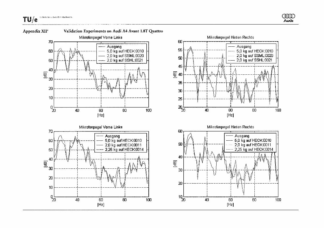
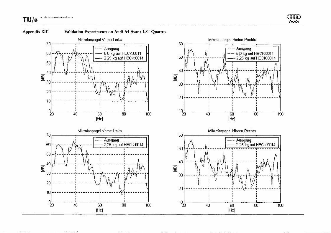
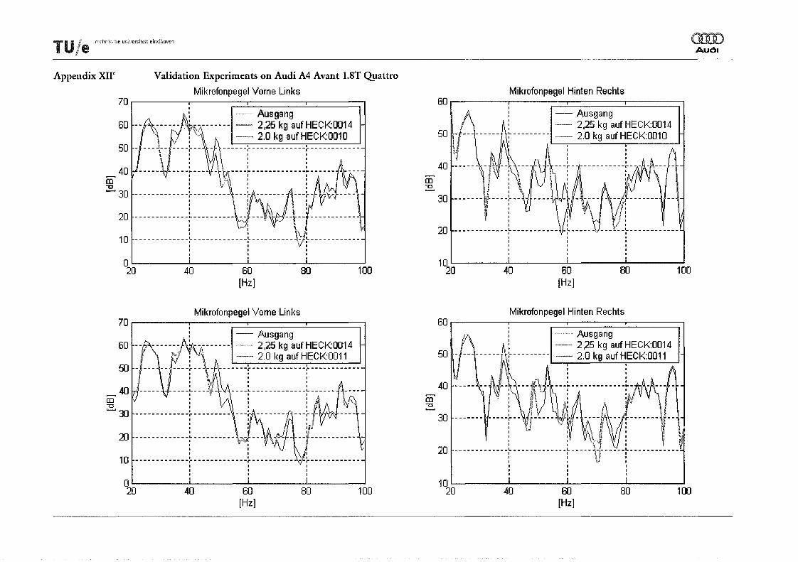
In Appendix XIIh-k the APS of the two microphones after mass applications are compared with the APS of the two microphones when no masses are applied.
- ,"",,,,,",,_ .. ,,"" 8T Quattro t vs 1 .8T Quattro) ==::;:=7-rUle ,,,',",,"'""" . r Sound Pressure Leve13.0LU~ga;~ ~6 Avant (3.0L V6 Fron . : ~_ ~~t ~ ~;oa~t
. ofInterlO gsmess : __, 86 Avant . XII' Companson I 'ch Ausgan :: _ Audi
AppendIX Verg el : i , ". 1.8T Quattro
: : ~ .. o , , , ..... , 10 : , : •••....•.••••• , .,A : i .......... +... i I }-01 " , , ........, , ' , c...... , , t\~/\O":;.:.. f/I,:~;""':. :-/;------------------,,------1 \I~ i i rA~-..,---------p