Berlin Institute of Technology D. Bieniek, R. Luckner – November 7 th /8 th , 2011 WakeNet3 - Europe Specific Workshop: Operational Wake Vortex Models Application of Wake Vortex Models in Encounter Simulations
Transcript
Berlin Institute ofTechnology D. Bieniek, R. Luckner
–
November 7th/8th, 2011WakeNet3 -
Europe Specific Workshop: Operational Wake Vortex Models
Application of Wake Vortex Models in Encounter Simulations
Slide 2D. Bieniek, R. Luckner November 7/8, 2011
Content
Flight Simulation
Parameter Studies
Simplified Encounter Simulation
Fast-time Simulations
Application of Vortex Models in…
Slide 3D. Bieniek, R. Luckner
Objectives
What we need…
For Encounter Simulation: (Objective: Simulate aircraft upset due to the vortices)
-
Models for vortex-induced velocity field
-
Approx. 1m resolution
-
Parametric models, scalable models
-
Analytical or numeric models
-
Models with low computational effort
(e.g. real-time or fast-time simulations)
Subject of th
is
presentation
For Detection, Warning and Avoidance Systems: (Objective: Evaluate potential of such systems)
-
Models for vortex transport by wind
-
Models for vortex descend by mutual induction
Slide 4D. Bieniek, R. Luckner
0 1 2 3 4 5 60
0.1
0.2
0.3
0.4
0.5
0.6
0.7
0.8
0.9
1
r / rc [-]
V /
V 0 [-]
Top HatGaussian (Lamb-Oseen, L-O)ProctorLow Order Algebraic (Burnham-Hallock, B-H)
November 7/8, 2011
Examples of Flow Field Models
Distance from Center r / rC [-]
Nor
mal
ized
Indu
ced
Velo
city
Limited accuracy
Low computational effort
Quick variation of parameters
Analytical Models e.g. Low-order algebraic
(Burnham-Hallock, B-H)
Numerical Simulation Data e.g. LES Data
22c rr
rπ2
V(r)
Γ
Source: I. De Visscher et al. (UCL)
Accurate data
High computational effort
Variation of parameters requires time consuming simulation
Slide 5D. Bieniek, R. Luckner November 7/8, 2011
Vortex-induced Forces and
Moments
Application of WV Models
Integration of Operational WV Models into WV Encounter Simulation
WVE SoftwareAerodynamic InteractionModels (AIM) e.g. Strip Method
Strips
Vortex Models Velocities + Shape
MWV
FWV
+
Vortex Trajectory
Vortex Data
Aircraft Trajectory
Aircraft Data
Wake encounter software package from S-WAKE is being improved continuously
Slide 6D. Bieniek, R. Luckner
Implementation of WV Models
PilotInputs
EngineModule
AerodynamicsModule
Sum ofForces andMoments
KinematicEquations
Integration
BasicFlight
SimulationGeometry andAerodynamic
Dataof the Aircraft
Configuration,Attitude
and Trajectoryof the Aircraft
Induced Forcesand Moments
WVE Software
InverseAerodynamics
[AERO]-1
EquivalentLinear
Wind Field
AIMWV
Vortex Trajectory and Vortex Data
Slide 7D. Bieniek, R. Luckner November 7/8, 2011
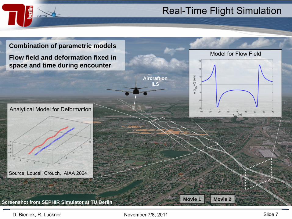
Real-Time Flight Simulation
Combination of parametric models
Flow field and deformation fixed in space and time during encounter
Movie 1
Analytical Model for Deformation
Screenshot from SEPHIR Simulator at TU Berlin
Aircraft on ILS
Source: Loucel, Crouch, AIAA 2004
Model for Flow Field
Movie 2
Slide 8D. Bieniek, R. Luckner
40 45 50 55 60 65 70-1
0
1Pilot Side-Stick Roll Input [-]
40 45 50 55 60 65 70-20
0
20Roll Angle [deg]
40 45 50 55 60 65 70-4
-2
0
2x 10⁶ Vortex Induced Rolling Moment [Nm]
time [s]
-5 0 5 10 15 20-1
0
1Pilot Side-Stick Roll Input [-]
-5 0 5 10 15 20-10
0
10
20Roll Angle [deg]
-5 0 5 10 15 20-4
-2
0
2x 10⁶ Vortex Induced Rolling Moment [Nm]
time [s]
November 7/8, 2011
Types of Real-Time Encounter Simulation
“Free” Encounters “Fixed” Encounters
Complete simulation of encounter
Multiple comparable
encounters
Fixed vortex disturbance
Multiple identical
encounters
Online computation of disturbance Pre-recorded disturbance
Slide 9D. Bieniek, R. Luckner November 7/8, 2011
Example of Fixed Encounters
Piloted encounters with curved vortices
Source: D. Vechtel
(DLR): “Curved wake vortices encounter simulations with pilots-in-the-loop”, WN3E Specific Workshop on Models and Methods for Wake Vortex Encounter Simulations, 2010
Size of follower aircraft (mainly wingspan, moment of inertia)
has significant impact on
Roll Acceleration Ratio versus rc
/bg
Simulations with B-H vortex model
Slide 13D. Bieniek, R. Luckner
Citation Do228 VFW614CRJ-700 F100 B737 A320 A3300
0.2
0.4
0.6
0.8
1
1.2
TC 198 - 199 = 100m2/s r
c = 2.5% b
g b
g = 79.80m
WV = 0.0°
WV = 0.0°
max
. rol
l acc
. / m
ax. r
oll a
cc.
BH
Low Order Algebraic (B-H) Gaussian (L-O)
November 7/8, 2011
Parameter Studies
Example: Vortex Model
( Max
. Rol
l Acc
. / M
ax. R
oll A
cc. (
B-H
Mod
el) [
°/s2 ]
)R
oll A
ccel
erat
ion
Rat
io [-
] Vortex model selection has
a significant impact on
Roll Acceleration Ratio
Effect varies with size of
follower aircraft
Validated parametric
vortex velocity field models
are needed
Slide 14D. Bieniek, R. Luckner November 7/8, 2011
Simplified Encounter Simulation
Recorded data from piloted flight simulations
Simplified WVE simulation model
-8 -6 -4 -2 0 2 4 6 8-20
-10
0
10
20
Ban
k A
ngle
[°]
TC 444444 = 665m2/s WV
= -3° WV
= 10°
-8 -6 -4 -2 0 2 4 6 8-20
-10
0
10
20
30
Time [sec]
Rol
l Rat
e [°
/sec
]
Straight flight path to compute vortex disturbance
Linear 1DoF model for aircraft roll motion
Generic control surface deflections
(Pilot model + FCS model)
-100-50050100
-100
-50
0
50
100
-0.06-0.02
-0.02
0.02
0.02
0.06
y`gr [m]
z`gr
[m]
rolling moment coefficient
max: 0.09min: -0.09
z wv[m
]
yWV
[m]
Rolling moment coefficient
Simplified dynamic WVE model: option for RECAT Phase II or III methodology
Slide 15D. Bieniek, R. Luckner November 7/8, 2011
Fast-Time Simulations
Pilot Model
A/C Simulation Model
PilotInputs
WV Simulation
Model-40-30-20-10010203040
-20
-15
-10
-5
0
5
10
15
20
Lamb-OseenBurnham & HallockProctorWinckelmans
Vortex Disturbance
A/CResponse
Encounter Parameters
A/C - WVDistance
Worst-Case SearchAnti-optimization to identify worst-case encounter conditions
Exemplary Application:
G. Höhne, M. Fuhrmann, R. Luckner: „Critical wake vortex encounter scenarios“, Aerospace Science and Technology 8 (2004) 689–701, 2004
Slide 16D. Bieniek, R. Luckner November 7/8, 2011
Fast-Time Simulations
Risk AnalysisMonte-Carlo Simulations with tools such as VESA / WakeScene
Pilot Model
A/C Simulation Model
PilotInputs
WV Simulation
Model-40-30-20-10010203040
-20
-15
-10
-5
0
5
10
15
20
Lamb-OseenBurnham & HallockProctorWinckelmans
Vortex Disturbance
A/CResponse
Scenario (incl. Probability)
A/C - WVDistance
Risk
Multi-Parameter Severity Models
Slide 17D. Bieniek, R. Luckner November 7/8, 2011
Research Needs
Criteria and data for WV model validation are needed.
Uncertainties regarding values of important parameters have to be addressed (e.g. core radius, vortex span).
Interaction of aircraft surfaces and wake vortex flow field is not considered in current encounter simulations. How strong are the effects?
Slide 18D. Bieniek, R. Luckner November 7/8, 2011
Conclusions
Interdisciplinary cooperation between vortex modeling (fluid dynamics) and encounter simulation (flight dynamics) is important for model development (fit for purpose).
WVE simulation provides results on parameter sensitivities and importance of model parameters.
WV models in WVE simulations directly affect aircraft upsets (e.g. max. bank angle) and consequently pilot’s severity rating.
For severity assessments and safety analysis, validated WV (and WVE) models are essential.
Slide 19D. Bieniek, R. Luckner November 7/8, 2011
This document and all information contained herein is the sole property of TU Berlin. No intellectual property rights are granted by the delivery of this document or the disclosure of its content. This document shall not be reproduced or disclosed to a third party without the express written consent of TU Berlin. This document and its content shall not be used for any purpose other than that for which it is supplied.
The statements made herein do not constitute an offer. They are based on the mentioned assumptions and are expressed in good faith. Where the supporting grounds for these statements are not shown, TU Berlin will be pleased to explain the basis thereof.
Thank you for your attention!Thank you for your attention!Questions?Questions?