+ All Categories
Home > Documents > Application Reference Number: WWO10001 Tunnel and Bridge Assessments ·  · 2016-05-05DRAFT AND...

Application Reference Number: WWO10001 Tunnel and Bridge Assessments ·  · 2016-05-05DRAFT AND...

Date post: 12-Apr-2018
Category:
Upload: duonganh
View: 227 times
Download: 1 times
Share this document with a friend
73
Tunnel and Bridge Assessments Central Zone Lambeth Road Bridge Doc Ref: 9.15.59 Folder 101 September 2013 DCO-DT-000-ZZZZZ-091500 Thames Tideway Tunnel Thames Water Utilities Limited Application for Development Consent Application Reference Number: WWO10001
Transcript

Tunnel and Bridge AssessmentsCentral ZoneLambeth Road BridgeDoc Ref: 9.15.59

Folder 101 September 2013DCO-DT-000-ZZZZZ-091500

Lam

beth

Roa

d Br

idgeThames Tideway Tunnel

Thames Water Utilities Limited

Application for Development ConsentApplication Reference Number: WWO10001

DRAFT AND CONFIDENTIAL

Lambeth Bridge Assessment Report 315-RG-TPI-BR011-000001 Revision - AF Date approved -

i Printed 27/06/2012

Thames Tunnel

Assessment Report - Lambeth Road Bridge

List of contents

Page number

1 Executive summary ......................................................................................... 1

2 Introduction ...................................................................................................... 2

2.1 Scope ...................................................................................................... 2

2.2 Utilities ..................................................................................................... 2

2.3 Third Party Interfaces .............................................................................. 3

3 Structure Description ...................................................................................... 4

3.2 Structural Type ........................................................................................ 4

3.3 Foundation Type ...................................................................................... 4

3.4 Span Arrangements ................................................................................. 5

3.5 Articulation Arrangements ....................................................................... 5

3.6 Road Restraint system type..................................................................... 5

4 Background to Assessment ............................................................................ 6

4.1 Previous Assessment Summary .............................................................. 6

4.2 Current Weight Restrictions ..................................................................... 7

4.3 Monitoring ................................................................................................ 7

4.4 Inspection for Assessment to BD 95 ........................................................ 7

5 Assessment Method ........................................................................................ 8

5.1 General .................................................................................................... 8

5.2 Material Properties .................................................................................. 8

5.3 Loading .................................................................................................... 8

5.4 Structural Analysis ................................................................................... 9

5.5 Assessment Criteria .............................................................................. 10

6 Assessment Results ...................................................................................... 11

6.1 Summary of Results .............................................................................. 11

6.2 Deck Movement at supports .................................................................. 15

6.3 Assessment Results Discussion ............................................................ 16

6.4 Cat II Check ........................................................................................... 18

7 Mitigation Measures/Additional Work Recommendations ......................... 19

7.1 General .................................................................................................. 19

7.2 Substructure .......................................................................................... 19

DRAFT AND CONFIDENTIAL

Lambeth Bridge Assessment Report 315-RG-TPI-BR011-000001 Revision - AF Date approved -

ii Printed 27/06/2012

7.3 Superstructure ....................................................................................... 19

7.4 Expansion Joints and Bearings ............................................................. 19

Appendix A – Load Summary ................................................................................ 23

Appendix B – Models ............................................................................................. 28

Appendix C – Geotechnical Assessment Results ............................................... 29

Appendix D – Settlement Summary ...................................................................... 39

Appendix E – Cat II Check Results & Comparison .............................................. 40

Appendix F – Settlement Drawing ......................................................................... 45

DRAFT AND CONFIDENTIAL

Lambeth Bridge Assessment Report 315-RG-TPI-BR011-000001 Revision - AF Date approved -

iii Printed 27/06/2012

List of figures

Page number

Figure 3.1 Inner rib, centre span, showing strengthening method adopted ............... 7

List of tables

Page number

Table 2.1: Summary of Utilities affected by settlement of bridge ................................ 2

Table 6.1: Assessment Results ................................................................................ 15

Table 6.2: Displacement Summary at Deck Level .................................................... 15

Table 6.3: Longitudinal Displacement ....................................................................... 16

Table 6.4: Transverse Displacements ...................................................................... 16

List of abbreviations

AIP Approval in Principal

1 Executive summary

Lambeth Bridge Assessment Report 315-RG-TPI-BR011-000001 Revision - AF Date approved -

Page 1 Uncontrolled when printed Printed 27/06/2012

DRAFT AND CONFIDENTIAL

1 Executive summary

1.1.1 The assessment was carried out to assess the structural adequacy of the bridge to resist the predicted ground settlement due to the construction of the Thames Tunnel. Structural adequacy was determined using the results from the assessment completed by Kumar Associates in 1996 in combination with the results from the analysis for differential settlement due to the tunnel construction.

1.1.2 This document sets out the results of the detailed assessment of Lambeth Road Bridge.

1.1.3 The structure was found to be adequate where loads were added to the previous assessment findings with usage factors found to be less than 1.0.

1.1.4 For members that were not previously assessed, including the bracing members and other transverse members a full usage factor could not be directly determined. Further work has shown that these members can also be considered as adequate for the differential settlement effects.

2 Introduction

Lambeth Bridge Assessment Report 315-RG-TPI-BR011-000001 Revision - AF Date approved -

Page 2 Uncontrolled when printed Printed 27/06/2012

DRAFT AND CONFIDENTIAL

2 Introduction

2.1 Scope

2.1.1 This report presents the assessment of the impact of the predicted ground movement from the proposed Thames Tunnel on the Lambeth Road Bridge.

2.1.2 This report sets out the assessed results for the settlement effects and where possible considers these in conjunction with load effects derived from previous assessment of the structure.

2.2 Utilities

2.2.1 The utilities set out in Table 2.1 have been identified as crossing the structure, and as such are affected by the movement of the bridge.

Utility

Description No. Type Location

Asset Owner

(current) Utility Type

BT Ducts TBC TBC Northern Footway BT Telecoms Cables

Cable &

Wireless Ducts

TBC TBC Northern Footway Cable & Wireless Fibre Optic

Telecoms Cables

Trunk Main TBC TBC Northern Footway Thames Water

& Sewer Water & Sewer

Bridge Lighting

(GLC)

1 2" Cast Iron Northern Footway UK Power

Networks (EDF) Electric Cables

BT Ducts TBC TBC Southern Footway BT Telecoms Cables

Cable &

Wireless Ducts

TBC TBC Southern Footway Cable & Wireless Fibre Optic

Telecoms Cables

Colt 4 TBC Southern Footway McNicholas Colt Fibre Optic

Telecoms Cables

euNetworks

Duct TBC TBC Southern Footway euNetworks

Fibre Optic

Telecoms Cables

Global

Crossing

Duct

TBC TBC Southern Footway Global Crossing Fibre Optic

Telecoms Cables

Trunk Main TBC TBC Southern Footway Thames Water

& Sewer Water & Sewer

Service 1 3" (Wrought?)

Iron Southern Footway

UK Power Networks (EDF)

Electric Cables

VZB Backbone

Duct

TBC TBC Southern Footway Verizon Business Fibre Optic

Telecoms Cables

ES Pipelines TBC LP TBC (Assumed - No Map Available)

ES Pipelines Gas - Local Transmission

System

Table 2.1: Summary of Utilities affected by settlement of bridge

2 Introduction

Lambeth Bridge Assessment Report 315-RG-TPI-BR011-000001 Revision - AF Date approved -

Page 3 Uncontrolled when printed Printed 27/06/2012

DRAFT AND CONFIDENTIAL

2.3 Third Party Interfaces

2.3.1 A meeting was held on 30/06/11 with representatives from TfL to agree the AIP. The contents of the AIP were agreed at this meeting, with only minor amendments to the original version of the AIP

3 Structure Description

Lambeth Bridge Assessment Report 315-RG-TPI-BR011-000001 Revision - AF Date approved -

Page 4 Uncontrolled when printed Printed 27/06/2012

DRAFT AND CONFIDENTIAL

3 Structure Description

3.1.1 The current Lambeth Road Bridge was designed by Sir George Humphreys and was opened to traffic in July 1932.

3.1.2 Lambeth Bridge is a road traffic (A3203) and footbridge crossing the River Thames in an east-west direction in Central London. The structure links Lambeth Palace to Milbank and Westminster. The bridge is symmetrical about its centre line with a central span of 50.3m and four equal spanning lengths of 46.55m. The total length of the bridge is 236.50m.

3.1.3 The width of the structure between parapets is 18.30m (i.e. 11.0m roadway with 3.65m footway on each side). The structure carries three lanes of traffic; one general traffic lane in each direction and one bus lane heading from the Lambeth abutment towards the Westminster abutment.

3.1.4 The primary deck is made of steel longitudinal girders with steel troughing and reinforced concrete on top, and transverse and diagonal steel girders in between. All the five spans are simply supported on reinforced concrete piers which are clad with granite blocks.

3.1.5 There are metal parapets (balustrades) along the edges of the carriageway for the full length of the structure. The balustrade is of cast iron seated on steel cornice and it is surmounted by cast iron lamp standards, two on either side of the bridge in each span. There are also granite lamp standards above the carved panels over the buttresses at the ends of each pier. These piers and buttresses with the standards and panels are granite. There are obelisks on either side of the bridge approaches and these are also granite; each stands on a pedestal and terminated by a pineapple finial.

3.1.6 The bridge was assessed in 1996 and it was found that the central web plate of the inner ribs towards the middle of the spans failed to meet the stress limitation criterion for the 40 t assessment live loading, indicating only a 17 t (gvw) vehicle capacity for the bridge. The bridge was subsequently strengthened in order to have adequate capacity for 40 tonne loading in accordance with BD 21/93.

3.1.7 The bearings have been the subject of special inspection investigation by Hyder Consultants in February 2008.

3.2 Structural Type

3.2.1 Each of the five spans consists of steel arches pinned at the supports (pier/abutment). The horizontal deck member is supported vertically on sliding plates at the intermediate piers and on elastomeric bearings at the abutment.

3.3 Foundation Type

3.3.1 The foundations for the piers and abutments consist of mass concrete.

3 Structure Description

Lambeth Bridge Assessment Report 315-RG-TPI-BR011-000001 Revision - AF Date approved -

Page 5 Uncontrolled when printed Printed 27/06/2012

DRAFT AND CONFIDENTIAL

3.4 Span Arrangements

3.4.1 The bridge is symmetrical about its centre line with spans of 46.55m, 46.55m, 50.3m, 46.55m and 46.55m. The total structure length is 236.5m.

3.5 Articulation Arrangements

3.5.1 The arch ribs are supported by pin bearings at the intermediate piers and abutments. The types of bearings used at deck level are not mentioned and there is no mention of the articulation arrangement. However, it is likely that the articulation arrangement allows longitudinal movement at each end of the structure as there are expansion joints located at the face of each side of the pier and at each abutment.

3.6 Road Restraint system type

3.6.1 The road restraint system consists of cast iron parapets seated on steel. The containment type is unknown.

4 Background to Assessment

Lambeth Bridge Assessment Report 315-RG-TPI-BR011-000001 Revision - AF Date approved -

Page 6 Uncontrolled when printed Printed 27/06/2012

DRAFT AND CONFIDENTIAL

4 Background to Assessment

4.1 Previous Assessment Summary

4.1.1 The bridge was previously assessed using BD 21/93, for the assessment loading and BS 5400-3:1982 for the structural adequacy. This assessment was completed by Kumar Associates in 1996.

4.1.2 The assessment considered the structure as a series of line beam and plane frame models. The assessment method was considered appropriate based on the similarity to the original design philosophy and does not consider any transverse load distribution.

4.1.3 The internal trussed arches were idealised using beam column and bracing elements, with the middle ‘plated’ web portions of the spans being represented by trapezoidal finite ‘plate’ elements. The central panels of the ‘plated’ areas had additional side ‘cover’ plates applied to them, which effectively triples the web thickness in these parts. This was represented by triple thickness being specified for these finite elements in the computer analyses.

4.1.4 Some items such as cross bracing and cross beams were not assessed.

4.1.5 Only the central span of the bridge was assessed and it is assumed that because of the similarity between the different spans, the central span was selected as having the most onerous loading.

4.1.6 The previous assessment reported that all parts of the bridge, including the various connection details, would have passed the 40 t assessment live loading criteria. However, it was noted that the additional side ‘cover’ plates had not been overlapped or integrated with the flanges of the girders, being simply butted against the corner connecting angles of the section. Such a detail would not permit smooth shear flow to occur (especially the horizontal shear stress) between the elements of the section at these locations. Consequently, the resultant stress would have to ‘squeeze’ through the single central web plate between the rivets at this location, locally tripling its intensity. Using the single plate thickness as being effective at such locations, the central web plate failed to meet the stress limitation criterion for the 40t assessment live loading, indicating only a 17t (gvw) vehicle capacity for the bridge.

4.1.7 Subsequent strengthening works were carried out on Lambeth Bridge and involved the application of additional strips of cover plates at the location of the butt joint overlapping the web cover plates and the flange angles, leading to the strengthening detail shown in Figure 3.1. The addition of this strengthening lead to an assessment rating of 40 tonnes for this structure.

4 Background to Assessment

Lambeth Bridge Assessment Report 315-RG-TPI-BR011-000001 Revision - AF Date approved -

Page 7 Uncontrolled when printed Printed 27/06/2012

DRAFT AND CONFIDENTIAL

Figure 3.1 Inner rib, centre span, showing strengthening method adopted

4.2 Current Weight Restrictions

4.2.1 Lambeth Bridge has an assessment live load capacity of 40 Tonnes.

4.3 Monitoring

4.3.1 There is currently no monitoring present on the structure.

4.4 Inspection for Assessment to BD 95

4.4.1 As part of the assessment process, an inspection for assessment was carried out. This was done in order to identify any items/problems that needed to be taken into account during the assessment. These findings are recorded in 315-RI-TPI-BR011-000001-AB-Lambeth Bridge, which sets out the findings of the inspection for assessment. A condition factor of 1.0 was recommended for all elements of the structure.

5 Assessment Method

Lambeth Bridge Assessment Report 315-RG-TPI-BR011-000001 Revision - AF Date approved -

Page 8 Uncontrolled when printed Printed 27/06/2012

DRAFT AND CONFIDENTIAL

5 Assessment Method

5.1 General

5.1.1 The structure was assessed to determine the impacts of constructing the Thames Tunnel beneath the structure. The construction of the tunnel has the potential to cause settlement at the supports depending on the proximity of the abutment/pier to the tunnel, amongst other factors. These ground movements could potentially lead to differential settlement between the different piers thereby impacting on the integrity of the structure.

5.1.2 The differential settlement was quantified as part of the geotechnical assessment outlined in Appendix C.

5.1.3 The deck structure was assessed quantitatively for the impacts of the differential settlement. The substructure, including the piers/abutments and the foundations were assessed qualitatively.

5.1.4 Movements/rotations at the supports caused by the settlement were also assessed as this will affect the existing expansion joints and bearings.

5.1.5 As stated in the AIP, the assessment is not a full load assessment in the traditional sense, rather an assessment of the differential load effects arising from predicted ground movements due to tunnel construction. Therefore, only the derivation of the differential settlement loadcase was considered in detail. All other load effects were derived from the previous assessment report where available.

5.1.6 Where members have not been considered previously, the member resistance was calculated and the percentage increase in load is reported based on the total capacity of the section considered. An increase in load of up to 5% of the calculated member resistances will be considered adequate. This limit is considered to be acceptable when considering a steel structure. Where this percentage increase is not met further analysis, including calculation of further load effects will be undertaken.

5.1.7 Soil structure interaction was not considered as part of the assessment when looking at the effects of differential settlement on the utilities.

5.2 Material Properties

5.2.1 The main deck structure is constructed from steel. The material properties for this were derived based on the properties set out in BD 21/01.

5.3 Loading

5.3.1 Only the differential settlement loadcase was considered as part of the initial assessment. Where members are identified as being inadequate then calculation of further load effects will be undertaken, as necessary.

5.3.2 Therefore, as part of the assessment, the local geology for the bridge location was reviewed and ‘moderately conservative volume loss’ values

5 Assessment Method

Lambeth Bridge Assessment Report 315-RG-TPI-BR011-000001 Revision - AF Date approved -

Page 9 Uncontrolled when printed Printed 27/06/2012

DRAFT AND CONFIDENTIAL

derived. This was done by using the moderately conservative 1% volume loss, which is considered to be appropriate for the assessment stages considered in this report.

5.3.3 The differential settlement applied to the structure was then based on the geotechnical studies on the predicted settlement. The full geotechnical report is set out in Appendix C. The purpose of this assessment is to determine the typical settlements/rotations occurring at each of the piers and abutments. From this the impact on the structure will be determined.

5.3.4 The geotechnical analysis did not take into account the interaction of the structure in the calculations for the settlement. This is a conservative approach as the structure will in reality resist rotational movement of the support (pier).

5.3.5 It is noted that the assessment utilised BD 21/93 for the live loading calculations. A comparison between the basic loading from BD 21/84 and BD 21/01 shows that the loading for 40 tonne traffic is the same. However, the lane factors in BD21/93 are higher for lanes 3 and 4 with load factors of 0.6 applied to the 40 tonne loading. The lane factors for lanes 3 and 4 in BD 21/01 are 0.5 and 0.4.

5.3.6 BD 21/84 does not specifically require the consideration of temperature effects on the structure, though there is a reference that other loads not mentioned in BD 21/84 are to be used if considered significant. It is not clear from the assessment report whether temperature was considered previously in the assessment. For this structure, temperature effects are considered to have a significant impact on the structure, particularly the arch member. Currently, the effect of temperature has not considered in these assessment results.

5.4 Structural Analysis

5.4.1 The structure has been analysed using two 3D linear elastic space frame models using SuperSTRESS. A model was created for the centre span and also for the intermediate spans affected by the differential settlement caused by the construction of Thames Tunnel. The shore spans were not affected by the construction of the tunnel and therefore a model was not created for these spans. The 3D models were used for the assessment to review the implications of the settlement loads.

5.4.2 Four typical load cases were considered for the differential settlement. These were based on the predicted movements of the piers set out in Appendix C. The four loadcases included three typical intermediate positions of the tunnel boring machine and the final long term condition. The tunnel boring machine positions considered for the purposes of the analysis were 30m, 0m, -25m and -65m. At each of these positions, the differential settlements of the structure were calculated. The positions are measured from the point of intersection between the centreline of the bridge and the line of the tunnel boring machine. See Appendix C.5 for the definition of the point of intersection. These distances are measured from the centreline on the bridge. These positions were selected as they were considered to cause the most onerous loading on the structure.

5 Assessment Method

Lambeth Bridge Assessment Report 315-RG-TPI-BR011-000001 Revision - AF Date approved -

Page 10 Uncontrolled when printed Printed 27/06/2012

DRAFT AND CONFIDENTIAL

5.4.3 The load effects caused by the differential settlement were considered for each span. These effects were then compared with the resistances of the relevant section.

5.5 Assessment Criteria

5.5.1 For members which have previously been assessed, the acceptability of the build-up of the load effects will be based on the total sum of the applied loads, including the settlement compared with the total load resistance. The usage factor from this will then be reported. Usage factors above 1.0 indicate potential overstresses and usage factors less than 1.0 indicate adequacy of the structure.

5.5.2 For members that were not previously considered in the assessment and where the previous loading cannot be quantified, an increase in load of up to 5% of the calculated member resistances will be considered adequate. This limit is considered to be acceptable when considering a steel structure. Where this threshold value is exceeded further analysis will be undertaken.

6 Assessment Results

Lambeth Bridge Assessment Report 315-RG-TPI-BR011-000001 Revision - AF Date approved -

Page 11 Uncontrolled when printed Printed 27/06/2012

DRAFT AND CONFIDENTIAL

6 Assessment Results

6.1 Summary of Results

6.1.1 In the calculations made for the resistances of the sections, there was no allowance made for the lack of straightness of the members as no measurements for straightness were taken on site. The inspection for assessment did not identify any areas where this was thought to be of concern

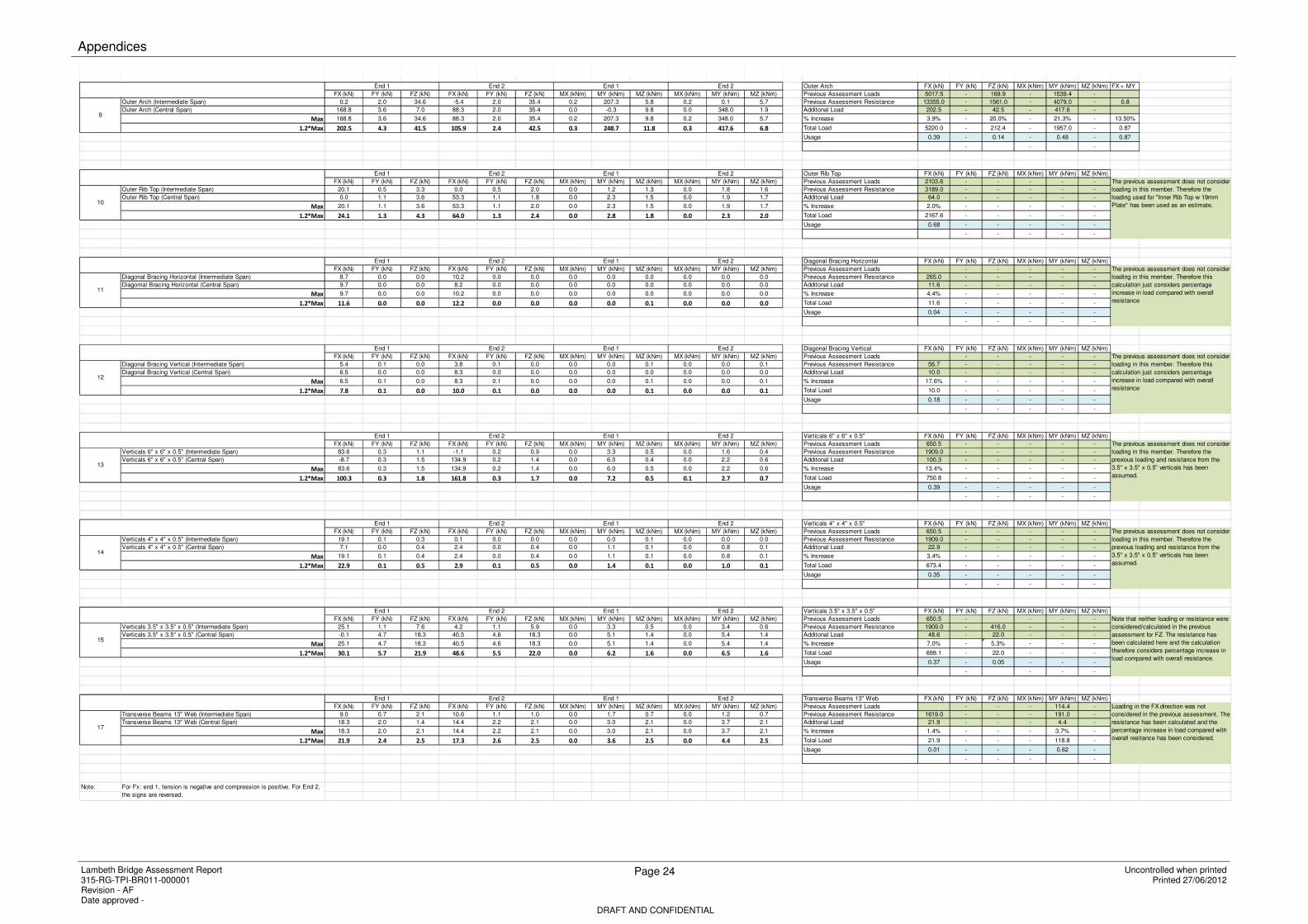
6.1.2 A summary of results for each of the sections is set out in Table 6.1 below. Where possible the loads have been added to the previous assessment loads and compared with the resistances derived at the previous assessment. Where the section considered was not checked previously, the loads are compared with the calculated member resistance. Where deemed appropriate the loads for members not specifically considered in the previous assessment have been estimated based on those used for similar members in the previous assessment.

6.1.3 Appendix A.1 includes the full loading summary of all loadcases. Appendix A.2 shows the loading summary for the long term condition only.

6.1.4 The loads set out in Table 6.1 consider the maximum loads in the member. Maximum loads are considered in combination. An allowance has not been made for coexistent effects, as these are not available from the original assessment

Inner Rib Top w 19mm Plate FX (kN) FY (kN) FZ (kN)

MX (kNm)

MY (kNm)

MZ (kNm) FX + MY

Previous Assessment Loads 2103.6 - 41.3 - 26.0 -

Note that resistances for FZ and MY were not calculated in the previous assessment but have been calculated here for comparison purposes for this assessment.

Previous Assessment Resistance 3867.0 - 1068.0 - 617.9 - 0.6

Additional Load 282.2 - 95.4 - 85.3 -

% Increase 11.8% - 68.9% - 76.6% - 26.48%

Total Load 2385.8 - 136.7 - 111.3 - 0.80

Usage 0.62 - 0.13 - 0.18 - 0.80

- - -

Inner Rib Top w 19mm & 15.9mm Plates FX (kN) FY (kN) FZ (kN)

MX (kNm)

MY (kNm)

MZ (kNm) FX + MY

Previous Assessment Loads 2998.7 - 19.4 - 10.3 -

Resistances for FZ and MY were not calculated in the previous assessment. The resistances calculated for the "Inner Rib Top w 19mm Plate" have been used as a conservative estimate.

Previous Assessment Resistance 4786.0 - 1068.0 - 617.9 - 0.6

Additional Load 312.9 - 18.9 - 74.9 -

% Increase 9.4% - 49.3% - 87.9% - 22.48%

Total Load 3311.6 - 38.3 - 85.2 - 0.83

Usage 0.69 - 0.04 - 0.14 - 0.83

- - -

6 Assessment Results

Lambeth Bridge Assessment Report 315-RG-TPI-BR011-000001 Revision - AF Date approved -

Page 12 Uncontrolled when printed Printed 27/06/2012

DRAFT AND CONFIDENTIAL

Inner Rib Bottom Triple Web FX (kN) FY (kN) FZ (kN)

MX (kNm)

MY (kNm)

MZ (kNm)

Previous Assessment Loads 5422.5 - 25.2 - 52.1 -

The previous assessment does not consider loading in this member. The loads and resistances for the "Inner Rib Bottom Single Web" have been used as a conservative estimate.

Previous Assessment Resistance 8678.0 - 939.0 - 2106.4 -

Additional Load 95.0 - 22.7 - 8.7 -

% Increase 1.7% - 47.4% - 14.3% -

Total Load 5517.5 - 47.9 - 60.8 -

Usage 0.64 - 0.05 - 0.03 -

- - -

Inner Rib Bottom Single Web FX (kN) FY (kN) FZ (kN)

MX (kNm)

MY (kNm)

MZ (kNm) FX + MY

Previous Assessment Loads 5422.5 - 25.2 - 52.1 -

Resistances for FZ and MY have been calculated as only loading was considered in the previous assessment.

Previous Assessment Resistance 8678.0 - 939.0 - 2106.4 - 0.6

Additional Load 375.4 - 55.4 - 285.4 -

% Increase 6.5% - 68.7% - 84.6% - 17.32%

Total Load 5797.9 - 80.6 - 337.5 - 0.79

Usage 0.67 - 0.09 - 0.16 - 0.79

- - -

Channels 10" x 3" FX (kN) FY (kN) FZ (kN) MX

(kNm) MY

(kNm) MZ

(kNm)

Previous Assessment Loads 324.2 - - - - -

Note that loading is negligible other than for FX

Previous Assessment Resistance 1006.0 - - - - -

Additional Load 63.9 - - - - -

% Increase 16.5% - - - - -

Total Load 388.1 - - - - -

Usage 0.39 - - - - -

- - - - -

Channels 10" x 3.5" FX (kN) FY (kN) FZ (kN) MX

(kNm) MY

(kNm) MZ

(kNm)

Previous Assessment Loads 684.9 - - - - -

Note that loading is negligible other than for FX

Previous Assessment Resistance 1281.0 - - - - -

Additional Load 109.0 - - - - -

% Increase 13.7% - - - - -

Total Load 793.9 - - - - -

Usage 0.62 - - - - -

- - - - -

6 Assessment Results

Lambeth Bridge Assessment Report 315-RG-TPI-BR011-000001 Revision - AF Date approved -

Page 13 Uncontrolled when printed Printed 27/06/2012

DRAFT AND CONFIDENTIAL

Inner Rib Triple Web FX (kN) FY (kN) FZ (kN) MX

(kNm) MY

(kNm) MZ

(kNm) FX + MY

Previous Assessment Loads 6121.4 - 207.3 - 1878.1 -

The previous assessment does not consider loading in this member. Therefore, the loading used in the previous assessment for the "Outer Arch" has been factored up and resistances have been calculated.

Previous Assessment Resistance 23122.0 - 6009.0 - 6809.0 - 0.5

Additional Load 77.1 - 15.9 - 403.7 -

% Increase 1.2% - 7.1% - 5.9% - 10.38%

Total Load 6196.7 - 223.2 - 2281.8 - 0.60

Usage 0.27 - 0.04 - 0.34 - 0.60

- - -

Outer Arch FX (kN) FY (kN) FZ (kN) MX

(kNm) MY

(kNm) MZ

(kNm) FX + MY

Previous Assessment Loads 5017.5 - 169.9 - 1539.4 -

Previous Assessment Resistance 13355.0 - 1561.0 - 4079.0 - 0.8

Additional Load 202.5 - 42.5 - 417.6 -

% Increase 3.9% - 20.0% - 21.3% - 13.50%

Total Load 5220.0 - 212.4 - 1957.0 - 0.87

Usage 0.39 - 0.14 - 0.48 - 0.87

- - -

Outer Rib Top FX (kN) FY (kN) FZ (kN) MX

(kNm) MY

(kNm) MZ

(kNm)

Previous Assessment Loads 2103.6 - - - - -

The previous assessment does not consider loading in this member. Therefore the loading used for "Inner Rib Top w 19mm Plate" has been used as an estimate.

Previous Assessment Resistance 3189.0 - - - - -

Additional Load 64.0 - - - - -

% Increase 2.0% - - - - -

Total Load 2167.6 - - - - -

Usage 0.68 - - - - -

- - - - -

Diagonal Bracing Horizontal FX (kN) FY (kN) FZ (kN)

MX (kNm)

MY (kNm)

MZ (kNm)

Current Assessment Loads 1.64 - - - - -

The previous assessment does not consider loading in this member. Required bracing loads have been calculated in accordance with BS5400 – Part 3, Clause 9.12.2

Previous Assessment Resistance 265.0 - - - - -

Additional Load 11.6 - - - - -

% Increase 87.6% - - - - -

Total Load 13.2 - - - - -

Usage 0.05 - - - - -

- - - - -

6 Assessment Results

Lambeth Bridge Assessment Report 315-RG-TPI-BR011-000001 Revision - AF Date approved -

Page 14 Uncontrolled when printed Printed 27/06/2012

DRAFT AND CONFIDENTIAL

Diagonal Bracing Vertical FX (kN) FY (kN) FZ (kN) MX

(kNm) MY

(kNm) MZ

(kNm)

Current Assessment Loads 2.4 - - - - -

The previous assessment does not consider loading in this member. Required bracing loads have been calculated in accordance with BS5400 – Part 3, Clause 9.12.2

Previous Assessment Resistance 56.7 - - - - -

Additional Load 10.0 - - - - -

% Increase 80.4% - - - - -

Total Load 12.4 - - - - -

Usage 0.22 - - - - -

- - - - -

Verticals 6" x 6" x 0.5" FX (kN) FY (kN) FZ (kN) MX

(kNm) MY

(kNm) MZ

(kNm)

Previous Assessment Loads 650.5 - - - - -

The previous assessment does not consider loading in this member. Therefore the previous loading and resistance from the 3.5" x 3.5" x 0.5" verticals has been assumed.

Previous Assessment Resistance 1909.0 - - - - -

Additional Load 100.3 - - - - -

% Increase 13.4% - - - - -

Total Load 750.8 - - - - -

Usage 0.39 - - - - -

- - - - -

Verticals 4" x 4" x 0.5" FX (kN) FY (kN) FZ (kN) MX

(kNm) MY

(kNm) MZ

(kNm)

Previous Assessment Loads 650.5 - - - - -

The previous assessment does not consider loading in this member. Therefore the previous loading and resistance from the 3.5" x 3.5" x 0.5" verticals has been assumed.

Previous Assessment Resistance 1909.0 - - - - -

Additional Load 22.9 - - - - -

% Increase 3.4% - - - - -

Total Load 673.4 - - - - -

Usage 0.35 - - - - -

- - - - -

Verticals 3.5" x 3.5" x 0.5" FX (kN) FY (kN) FZ (kN) MX

(kNm) MY

(kNm) MZ

(kNm)

Previous Assessment Loads 650.5 - - - -

Note that neither loading or resistance were considered/calculated in the previous assessment for FZ. The resistance has been calculated here and the calculation therefore considers percentage increase in load compared with overall resistance.

Previous Assessment Resistance 1909.0 - 416.0 - - -

Additional Load 48.6 - 22.0 - - -

% Increase 7.0% - 5.3% - - -

Total Load 699.1 - 22.0 - - -

Usage 0.37 - 0.05 - - -

- - - -

6 Assessment Results

Lambeth Bridge Assessment Report 315-RG-TPI-BR011-000001 Revision - AF Date approved -

Page 15 Uncontrolled when printed Printed 27/06/2012

DRAFT AND CONFIDENTIAL

Transverse Beams 13" Web FX (kN) FY (kN) FZ (kN)

MX (kNm)

MY (kNm)

MZ (kNm)

Previous Assessment Loads - - - 114.4 -

Loading in the FX direction was not considered in the previous assessment. The resistance has been calculated and the percentage increase in load compared with overall resistance has been considered.

Previous Assessment Resistance 1619.0 - - - 191.0 -

Additional Load 21.9 - - - 4.4 -

% Increase 1.4% - - - 3.7% -

Total Load 21.9 - - - 118.8 -

Usage 0.01 - - - 0.62 -

- - - -

Shear Stress in Diagonal Bracing Connection:

Diagonal Bracing

Horizontal Vertical

Per Rivet: τx τx

Previous Assessment Loads The previous assessment does not consider loading in this member. The resistance to shear stress for both members (per rivet) was calculated and compared with the additional shear stress caused by the differential settlement.

Calculated Shear Stress Resistance 119.7 119.7

Additional Shear Stress 8.7 8.8

% Increase 7.3% 7.3%

Total Shear Stress 8.7 8.8

Usage 0.07 0.07

Table 6.1: Assessment Results

6.2 Deck Movement at supports

6.2.1 The movement at deck level was also considered. These deck movements will affect the adequacy of the bearings, expansion joints and services. Movement limits for these items need to be considered based on these predicted movements. A summary of the maximum and minimum values for the displacement is set out in Table 6.2 below. For a more detailed summary including the axis orientation, see Appendix D.

DX (mm)

DY (mm)

DZ (mm)

RX (deg)

RY (deg)

RZ (deg)

Maximum Settlement 4.5 1.2 -0.1 0 0.1 0

Minimum Settlement -1.5 -4 -5.6 0 -0.1 0

Table 6.2: Displacement Summary at Deck Level

6.2.2 For the bearings, the longitudinal movements from the assessment were compared with the design movement ranges predicted from temperature expansion and contraction. These movements are set out in Table 6.3. Generally, it was found that the movement ranges were in excess of 10% of the temperature movement range.

6 Assessment Results

Lambeth Bridge Assessment Report 315-RG-TPI-BR011-000001 Revision - AF Date approved -

Page 16 Uncontrolled when printed Printed 27/06/2012

DRAFT AND CONFIDENTIAL

6.2.3 The transverse movements of the bearings were also considered. These results are reported in Table 6.4.

Max Movement

(mm)

Min Movement

(mm)

Total movement

Range (mm)

Span (m)

movement range due

to temperature

(mm)

Dx -0.2 -1.5 1.3 50.3 30.18 4.3%

4.5 0.2 4.3 46.55 27.93 15.4%

Table 6.3: Longitudinal Displacement

Max Movement

(mm)

Min Movement

(mm)

Total movement

Range (mm)

Dy 1.2 -4.0 5.2

0.8 -1.2 2.0

Table 6.4: Transverse Displacements

6.3 Assessment Results Discussion

Substructure

6.3.1 The substructure was assessed qualitatively by consideration of the predicted movements affecting the foundations. As the ground movements are generally considered to be small, the impacts of the differential settlement due to the new tunnel construction was deemed to have a negligible effect on the abutments and the piers.

Superstructure

6.3.2 The previous assessment reported that the structure was adequate under full 40 tonne assessment live loading when considering a functional triple web plating where present (as installed by the strengthening works).

6.3.3 The results from this assessment confirm that the structure will remain adequate under full 40 tonne live loading following the differential settlement caused by the construction of Thames Tunnel.

Members not considered in Previous Assessment

6.3.4 For the Inner Rib Bottom Triple Web section (results given in Table 6.1) the load and capacity for the similar rib section with a single web was used as a conservative estimate. Although the percentage increase in load is large in FZ and MY, the usage remains negligible and the member is therefore considered adequate.

6.3.5 For the Inner Rib Triple Web section (near mid span) the loading was factored based on the reported loading on the Outer Arch. There is an increase in both FZ and MY of approximately 6% - 7% due to settlement when based on these factored loads, however the usage remains sufficiently low and the member is considered adequate.

6 Assessment Results

Lambeth Bridge Assessment Report 315-RG-TPI-BR011-000001 Revision - AF Date approved -

Page 17 Uncontrolled when printed Printed 27/06/2012

DRAFT AND CONFIDENTIAL

6.3.6 For the Outer Rib Top section the reported load from the Inner Rib Top with 19mm Plate was used as it is assumed to be similar. Based upon this, a small percentage increase in axial loading of 2.0% due to the settlement was observed. A usage factor of 0.68 indicates the member to be adequate.

6.3.7 For the diagonal bracing both in the horizontal and vertical planes, there are no other similar members that were assessed previously. The original design philosophy considered that the loading that can be placed on the individual ribs of the bridge with no transverse load distribution occurring. As such the transverse bracing members are considered to have been designed for restraint of compression flanges only. Previous assessment outlined in Section 4 also adopted this philosophy. Further analysis of diagonal bracing members has also considered this approach and evaluated bracing forces in accordance with BS5400-3 Cl. 9.12.2. This methodology demonstrates the diagonal bracing members to be adequate with a usage factor less than 1.0 when resisting the maximum of: force FR or ΣPf/80, in addition to the differential settlement forces. No wind or lateral live loading have been directly considered as these would require a full load assessment to be undertaken, however these load effects are considered to have a negligible effect on the bracing members. The shear stress in the connection for these members was also checked against their individual resistance capacity and the results show a usage factor of 0.07.

6.3.8 For the 3.5” x 3.5” x 0.5” verticals there is an increase in axial load of 7.0% over the previous assessment giving a usage factor of 0.37. As the 4” x 4” x 0.5” and 6” x 6” x 0.5” verticals were not considered in the previous assessment, the reported loading and resistance for the 3.5” x 3.5” x 0.5” members were used as a conservative estimate. All vertical sections were shown to be adequate based on this assumption.

6.3.9 For the Transverse Beams 13” Web the axial load and capacity were not considered in the previous assessment. There are no other similar members that were assessed previously, so the full loading on these sections cannot be quantified. The resistance was calculated and the additional load can be seen as negligible as the percentage of the member’s axial capacity used due to settlement is a maximum of 1.4%. The remaining cross beam sections were not considered in the analysis as they are all of larger cross section and with much smaller loads due to settlement given in the results.

Bearings and Joints

6.3.10 Little information is currently available on the movement of the bearings and joints. Calculations indicate that the expected movement range during the Thames Tunnel construction is likely to be up to 23.3% of the current predicted movement range. It is recommended that the joints and bearings are investigated prior to construction of the Thames Tunnel as detailed in Section 7.4.1.

6 Assessment Results

Lambeth Bridge Assessment Report 315-RG-TPI-BR011-000001 Revision - AF Date approved -

Page 18 Uncontrolled when printed Printed 27/06/2012

DRAFT AND CONFIDENTIAL

Utilities

6.3.11 For utility services crossing Lambeth Road Bridge each service has been checked for structural adequacy based upon the geotechnical assessment results set out in Appendix C. The conclusions of this work are presented within the separate Utilities Assessment Reports listed below

BT 315-RG-TPI-BR011-000002-AA

Cable & Wireless 315-RG-TPI-BR011-000003-AA

ES Pipelines 315-RG-TPI-BR011-000004-AA

euNetworks 315-RG-TPI-BR011-000005-AA

Global Crossing 315-RG-TPI-BR011-000006-AA

McNicholas Colt 315-RG-TPI-BR011-000007-AA

Thames Water & Sewer 315-RG-TPI-BR011-000008-AA

UK Power Networks (EDF) 315-RG-TPI-BR011-000009-AA

Verizon Business 315-RG-TPI-BR011-000010-AA

6.4 Cat II Check

6.4.1 The final member usages are generally similar between the assessment and the check. There is no disagreement on which elements fail and which pass either before or after the new settlements have occurred.

6.4.2 The differences in additional loading due to settlement between the assessment and the check have not been investigated further as the overall conclusions are similar. Should subsequent strengthening of failed elements be required, better agreement may be necessary as the extent and magnitude of mitigation measures will differ.

6.4.3 The assessment results are reported in section 6.1 and Appendix A. The check results have been included in Appendix E for visibility.

7 Mitigation Measures

Lambeth Bridge Assessment Report 315-RG-TPI-BR011-000001 Revision - AF Date approved -

Page 19 Uncontrolled when printed Printed 27/06/2012

DRAFT AND CONFIDENTIAL

7 Mitigation Measures/Additional Work Recommendations

7.1 General

7.1.1 Prior to tunnel construction, investigation and monitoring of the joints/bearings is required to ensure that they are articulating as predicted. This investigation/monitoring is to be agreed with TfL in advance of any construction being undertaken in order to allow sufficient time to obtain confidence in the assumptions made.

7.1.2 Monitoring should also be done on other parts of the structure to determine the behaviour of the structure prior to the tunnel construction. This monitoring should be maintained during the tunnel construction and post tunnel construction. The monitoring period pre/post tunnel construction is to be completed over a time period adequate to determine the normal behaviour of the structure.

7.1.3 During the construction of Thames Tunnel, it will be necessary to install monitoring equipment in order to ensure that the actual movements of the foundations are within the limits predicted by the Geotechnical Assessment. Control limits, agreed with TfL, will need to be set out to quantify when intervention is required to prevent damage to the structure.

7.2 Substructure

7.2.1 No specific mitigation measures are currently proposed for the substructure as the substructure is considered adequate.

7.3 Superstructure

7.3.1 No specific mitigation measures are currently proposed for the superstructure as it is considered to adequate pass its assessment.

7.4 Expansion Joints and Bearings

7.4.1 Prior to tunnel construction, investigation and monitoring of the joints/bearings is required to ensure that they are articulating as predicted. This is to ensure that the bearings/joints have not locked up. The investigation should also consider whether there is sufficient movement range available to allow for the additional movement due to the tunnel construction as well as the predicted temperature movement.

Bibliography

Lambeth Bridge Assessment Report 315-RG-TPI-BR011-000001 Revision - AF Date approved -

Page 20 Uncontrolled when printed Printed 27/06/2012

DRAFT AND CONFIDENTIAL

Bibliography

Kumar, A. 2003, Strengthening of London’s Lambeth Bridge, Structures & Buildings 156 Issue 2, pp151–164 Kumar, A. 1996, Assessment of Lambeth Bridge – Calculations Sheets, London Borough of Lambeth, January 1996

Glossary

Lambeth Bridge Assessment Report 315-RG-TPI-BR011-000001 Revision - AF Date approved -

Page 21 Uncontrolled when printed Printed 27/06/2012

DRAFT AND CONFIDENTIAL

Glossary

Term Description

AIP Approval in Principle

Glossary

Lambeth Bridge Assessment Report 315-RG-TPI-BR011-000001 Revision - AF Date approved -

Page 22 Uncontrolled when printed Printed 27/06/2012

DRAFT AND CONFIDENTIAL

Appendices

List of figures

Page number

Figure B.1 Plan View of Deck (Central Span) ........................................................... 28

Figure B.2 Side View of Deck (Central Span) ........................................................... 28

Figure B.3 Overall 3D Deck Model (Central Span) ................................................... 28

Figure C.1 Bridge Layout and Pier Position .............................................................. 30

Figure C.2 Development of a 3D settlement trough .................................................. 31

Figure C.3 R1, R2 in relation to approaching tunnel ................................................. 32

Figure D.1 Axis System relative to bridge deck ........................................................ 39

Appendices

Lambeth Bridge Assessment Report 315-RG-TPI-BR011-000001 Revision - AF Date approved -

Page 23 Uncontrolled when printed Printed 27/06/2012

DRAFT AND CONFIDENTIAL

Appendix A – Load Summary

A.1 Total Load Summary

Inner Rib Top w 19mm Plate FX (kN) FY (kN) FZ (kN) MX (kNm) MY (kNm) MZ (kNm) FX + MY

FX (kN) FY (kN) FZ (kN) FX (kN) FY (kN) FZ (kN) MX (kNm) MY (kNm) MZ (kNm) MX (kNm) MY (kNm) MZ (kNm) Previous Assessment Loads 2103.6 - 41.3 - 26.0 -

Inner Rib Top w 19mm Plate (Intermediate Span) 132.9 1.2 47.3 0.9 0.9 55.6 0.0 39.4 2.7 0.0 48.5 3.3 Previous Assessment Resistance 3867.0 - 1068.0 - 617.9 - 0.6

Inner Rib Top w 19mm Plate (Central Span) 0.0 2.9 95.4 235.2 2.8 36.8 0.0 71.1 4.1 0.0 17.2 4.0 Additonal Load 282.2 - 95.4 - 85.3 -

Max 132.9 2.9 95.4 235.2 2.8 55.6 0.0 71.1 4.1 0.0 48.5 4.0 % Increase 11.8% - 69.8% - 76.6% - 26.48%

1.2*Max 159.5 3.5 114.5 282.2 3.3 66.7 0.1 85.3 5.0 0.1 58.2 4.7 Total Load 2385.8 - 136.7 - 111.3 - 0.80

Usage 0.62 - 0.13 - 0.18 - 0.80

- - -

Inner Rib Top w 19mm & 15.9mm Plates FX (kN) FY (kN) FZ (kN) MX (kNm) MY (kNm) MZ (kNm) FX + MY

FX (kN) FY (kN) FZ (kN) FX (kN) FY (kN) FZ (kN) MX (kNm) MY (kNm) MZ (kNm) MX (kNm) MY (kNm) MZ (kNm) Previous Assessment Loads 2998.7 - 19.4 - 10.3 -

Inner Rib Top w 19mm & 15.9mm Plates (Intermediate Span) N/A N/A N/A N/A N/A N/A N/A N/A N/A N/A N/A N/A Previous Assessment Resistance 4786.0 - 1068.0 - 617.9 - 0.6

Inner Rib Top w 19mm & 15.9mm Plates (Central Span) -17.8 1.2 -0.7 260.8 1.0 15.7 0.0 -0.2 1.6 0.0 62.4 1.5 Additonal Load 312.9 - 18.9 - 74.9 -

Max -17.8 1.2 -0.7 260.8 1.0 15.7 0.0 -0.2 1.6 0.0 62.4 1.5 % Increase 9.4% - 49.3% - 87.9% - 22.48%

1.2*Max -21.3 1.4 -0.9 312.9 1.1 18.9 0.0 -0.2 1.9 0.0 74.9 1.7 Total Load 3311.6 - 38.3 - 85.2 - 0.83

Usage 0.69 - 0.04 - 0.14 - 0.83

- - -

Inner Rib Bottom Triple Web FX (kN) FY (kN) FZ (kN) MX (kNm) MY (kNm) MZ (kNm)

FX (kN) FY (kN) FZ (kN) FX (kN) FY (kN) FZ (kN) MX (kNm) MY (kNm) MZ (kNm) MX (kNm) MY (kNm) MZ (kNm) Previous Assessment Loads 5422.5 - 25.2 - 52.1 -

Inner Rib Bottom Triple Web (Intermediate Span) N/A N/A N/A N/A N/A N/A N/A N/A N/A N/A N/A N/A Previous Assessment Resistance 8678.0 - 939.0 - 2106.4 -

Inner Rib Bottom Triple Web (Central Span) 79.2 2.8 19.0 -0.3 1.5 -1.2 0.0 -3.6 7.2 0.0 7.3 0.3 Additonal Load 95.0 - 22.7 - 8.7 -

Max 79.2 2.8 19.0 -0.3 1.5 -1.2 0.0 -3.6 7.2 0.0 7.3 0.3 % Increase 1.7% - 47.4% - 14.3% -

1.2*Max 95.0 3.4 22.7 -0.4 1.8 -1.4 0.0 -4.3 8.6 0.0 8.7 0.3 Total Load 5517.5 - 47.9 - 60.8 -

Usage 0.64 - 0.05 - 0.03 -

- - -

Inner Rib Bottom Single Web FX (kN) FY (kN) FZ (kN) MX (kNm) MY (kNm) MZ (kNm) FX + MY

FX (kN) FY (kN) FZ (kN) FX (kN) FY (kN) FZ (kN) MX (kNm) MY (kNm) MZ (kNm) MX (kNm) MY (kNm) MZ (kNm) Previous Assessment Loads 5422.5 - 25.2 - 52.1 -

Inner Rib Bottom Single Web (Intermediate Span) -0.1 1.5 46.2 161.9 2.9 48.7 0.1 163.1 3.7 0.1 11.7 4.1 Previous Assessment Resistance 8678.0 - 939.0 - 2106.4 - 0.6

Inner Rib Bottom Single Web (Central Span) 312.8 0.9 3.5 -0.4 0.8 57.2 0.0 1.8 1.3 0.0 237.8 1.1 Additonal Load 375.4 - 55.4 - 285.4 -

Max 312.8 1.5 46.2 161.9 2.9 57.2 0.1 163.1 3.7 0.1 237.8 4.1 % Increase 6.5% - 68.7% - 84.6% - 21.58%

1.2*Max 375.4 1.8 55.4 194.3 3.5 68.6 0.1 195.7 4.5 0.1 285.4 4.9 Total Load 5797.9 - 80.6 - 337.5 - 0.83

Usage 0.67 - 0.09 - 0.16 - 0.83

- - -

Channels 10" x 3" FX (kN) FY (kN) FZ (kN) MX (kNm) MY (kNm) MZ (kNm)

FX (kN) FY (kN) FZ (kN) FX (kN) FY (kN) FZ (kN) MX (kNm) MY (kNm) MZ (kNm) MX (kNm) MY (kNm) MZ (kNm) Previous Assessment Loads 324.2 - - - - -

Channels 10" x 3" (Intermediate Span) -0.5 0.0 1.4 32.8 0.0 1.0 0.0 1.8 0.1 0.0 3.2 0.1 Previous Assessment Resistance 1006.0 - - - - -

Channels 10" x 3" (Central Span) 53.3 0.0 1.1 -0.9 0.0 1.7 0.0 6.1 0.1 0.0 2.6 0.1 Additonal Load 63.9 - - - - -

Max 53.3 0.0 1.4 32.8 0.0 1.7 0.0 6.1 0.1 0.0 3.2 0.1 % Increase 16.5% - - - - -

1.2*Max 63.9 0.1 1.7 39.3 0.1 2.1 0.0 7.3 0.1 0.0 3.8 0.2 Total Load 388.1 - - - - -

Usage 0.39 - - - - -

- - - - -

Channels 10" x 3.5" FX (kN) FY (kN) FZ (kN) MX (kNm) MY (kNm) MZ (kNm)

FX (kN) FY (kN) FZ (kN) FX (kN) FY (kN) FZ (kN) MX (kNm) MY (kNm) MZ (kNm) MX (kNm) MY (kNm) MZ (kNm) Previous Assessment Loads 684.9 - - - - -

Channels 10" x 3.5" (Intermediate Span) -1.4 0.0 0.7 56.0 0.1 0.8 0.0 1.0 0.1 0.0 1.4 0.1 Previous Assessment Resistance 1281.0 - - - - -

Channels 10" x 3.5" (Central Span) 90.9 0.1 0.7 -4.2 0.1 0.0 0.0 -0.1 0.1 0.0 0.2 0.2 Additonal Load 109.0 - - - - -

Max 90.9 0.1 0.7 56.0 0.1 0.8 0.0 1.0 0.1 0.0 1.4 0.2 % Increase 13.7% - - - - -

1.2*Max 109.0 0.1 0.9 67.2 0.1 1.0 0.0 1.2 0.2 0.0 1.7 0.2 Total Load 793.9 - - - - -

Usage 0.62 - - - - -

- - - - -

Inner Rib Triple Web FX (kN) FY (kN) FZ (kN) MX (kNm) MY (kNm) MZ (kNm) FX + MY

FX (kN) FY (kN) FZ (kN) FX (kN) FY (kN) FZ (kN) MX (kNm) MY (kNm) MZ (kNm) MX (kNm) MY (kNm) MZ (kNm) Previous Assessment Loads 6121.4 - 207.3 - 1878.1 -

Inner Rib Triple Web (Intermediate Span) -0.7 2.0 8.6 44.2 1.3 6.8 0.7 221.3 4.8 0.7 -8.5 5.0 Previous Assessment Resistance 23122.0 - 6009.0 - 6809.0 - 0.5

Inner Rib Triple Web (Central Span) 64.3 0.4 3.5 -1.1 0.0 13.3 0.0 -20.7 1.0 0.0 336.4 0.4 Additonal Load 77.1 - 15.9 - 403.7 -

Max 64.3 2.0 8.6 44.2 1.3 13.3 0.7 221.3 4.8 0.7 336.4 5.0 % Increase 1.2% - 7.1% - 5.9% - 10.38%

1.2*Max 77.1 2.4 10.3 53.0 1.6 15.9 0.9 265.6 5.8 0.9 403.7 6.0 Total Load 6198.5 - 223.2 - 2281.8 - 0.60

Usage 0.27 - 0.04 - 0.34 - 0.60

- - -

8

End 1 End 2 End 1 End 2

End 1 End 2 End 1 End 2

6

End 1 End 2 End 1 End 2

5

End 1 End 2 End 1 End 2

End 1 End 2 End 1 End 2

Note that resistances for FZ and

MY were not calculated in the

previous assessment but have

been calculated here for the

purpose of analysis.

Resistances for FZ and MY

were not calculated in the

previous assessment. The

resistances calculated for the

"Inner Rib Top w 19mm Plate"

have been used as a

conservative estimate.

Resistances for FZ and MY have

been calculated as only loading

was considered in the previous

assessment.

The previous assessment does not consider

loading in this member. The loads and

resistances for the "Inner Rib Bottom Single

Web" have been used as a conservative

estimate.

1

End 1 End 2 End 1 End 2

2

4

End 1 End 2 End 1 End 2

3

Note that loading is negligible other than for

FX

Note that loading is negligible other than for

FX

The previous assessment does

not consider loading in this

member. Therefore, the loading

used in the previous assessment

for the "Outer Arch" has been

factored up and resitances have

been calculated.

Appendices

Lambeth Bridge Assessment Report 315-RG-TPI-BR011-000001 Revision - AF Date approved -

Page 24 Uncontrolled when printed Printed 27/06/2012

DRAFT AND CONFIDENTIAL

Outer Arch FX (kN) FY (kN) FZ (kN) MX (kNm) MY (kNm) MZ (kNm) FX + MY

FX (kN) FY (kN) FZ (kN) FX (kN) FY (kN) FZ (kN) MX (kNm) MY (kNm) MZ (kNm) MX (kNm) MY (kNm) MZ (kNm) Previous Assessment Loads 5017.5 - 169.9 - 1539.4 -

Outer Arch (Intermediate Span) 0.2 2.0 34.6 -5.4 2.0 35.4 0.2 207.3 5.8 0.2 0.1 5.7 Previous Assessment Resistance 13355.0 - 1561.0 - 4079.0 - 0.8

Outer Arch (Central Span) 168.8 3.6 7.0 88.3 2.0 35.4 0.0 -0.3 9.8 0.0 348.0 1.9 Additonal Load 202.5 - 42.5 - 417.6 -

Max 168.8 3.6 34.6 88.3 2.0 35.4 0.2 207.3 9.8 0.2 348.0 5.7 % Increase 3.9% - 20.0% - 21.3% - 13.50%

1.2*Max 202.5 4.3 41.5 105.9 2.4 42.5 0.3 248.7 11.8 0.3 417.6 6.8 Total Load 5220.0 - 212.4 - 1957.0 - 0.87

Usage 0.39 - 0.14 - 0.48 - 0.87

- - -

Outer Rib Top FX (kN) FY (kN) FZ (kN) MX (kNm) MY (kNm) MZ (kNm)

FX (kN) FY (kN) FZ (kN) FX (kN) FY (kN) FZ (kN) MX (kNm) MY (kNm) MZ (kNm) MX (kNm) MY (kNm) MZ (kNm) Previous Assessment Loads 2103.6 - - - - -

Outer Rib Top (Intermediate Span) 20.1 0.5 3.3 0.0 0.5 2.0 0.0 1.2 1.3 0.0 1.8 1.6 Previous Assessment Resistance 3189.0 - - - - -

Outer Rib Top (Central Span) 0.0 1.1 3.6 53.3 1.1 1.8 0.0 2.3 1.5 0.0 1.9 1.7 Additonal Load 64.0 - - - - -

Max 20.1 1.1 3.6 53.3 1.1 2.0 0.0 2.3 1.5 0.0 1.9 1.7 % Increase 2.0% - - - - -

1.2*Max 24.1 1.3 4.3 64.0 1.3 2.4 0.0 2.8 1.8 0.0 2.3 2.0 Total Load 2167.6 - - - - -

Usage 0.68 - - - - -

- - - - -

Diagonal Bracing Horizontal FX (kN) FY (kN) FZ (kN) MX (kNm) MY (kNm) MZ (kNm)

FX (kN) FY (kN) FZ (kN) FX (kN) FY (kN) FZ (kN) MX (kNm) MY (kNm) MZ (kNm) MX (kNm) MY (kNm) MZ (kNm) Previous Assessment Loads - - - - -

Diagonal Bracing Horizontal (Intermediate Span) 8.7 0.0 0.0 10.2 0.0 0.0 0.0 0.0 0.0 0.0 0.0 0.0 Previous Assessment Resistance 265.0 - - - - -

Diagomal Bracing Horizontal (Central Span) 9.7 0.0 0.0 8.2 0.0 0.0 0.0 0.0 0.0 0.0 0.0 0.0 Additonal Load 11.6 - - - - -

Max 9.7 0.0 0.0 10.2 0.0 0.0 0.0 0.0 0.0 0.0 0.0 0.0 % Increase 4.4% - - - - -

1.2*Max 11.6 0.0 0.0 12.2 0.0 0.0 0.0 0.0 0.1 0.0 0.0 0.0 Total Load 11.6 - - - - -

Usage 0.04 - - - - -

- - - - -

Diagonal Bracing Vertical FX (kN) FY (kN) FZ (kN) MX (kNm) MY (kNm) MZ (kNm)

FX (kN) FY (kN) FZ (kN) FX (kN) FY (kN) FZ (kN) MX (kNm) MY (kNm) MZ (kNm) MX (kNm) MY (kNm) MZ (kNm) Previous Assessment Loads - - - - -

Diagonal Bracing Vertical (Intermediate Span) 5.4 0.1 0.0 3.8 0.1 0.0 0.0 0.0 0.1 0.0 0.0 0.1 Previous Assessment Resistance 56.7 - - - - -

Diagonal Bracing Vertical (Central Span) 6.5 0.0 0.0 8.3 0.0 0.0 0.0 0.0 0.0 0.0 0.0 0.0 Additonal Load 10.0 - - - - -

Max 6.5 0.1 0.0 8.3 0.1 0.0 0.0 0.0 0.1 0.0 0.0 0.1 % Increase 17.6% - - - - -

1.2*Max 7.8 0.1 0.0 10.0 0.1 0.0 0.0 0.0 0.1 0.0 0.0 0.1 Total Load 10.0 - - - - -

Usage 0.18 - - - - -

- - - - -

Verticals 6" x 6" x 0.5" FX (kN) FY (kN) FZ (kN) MX (kNm) MY (kNm) MZ (kNm)

FX (kN) FY (kN) FZ (kN) FX (kN) FY (kN) FZ (kN) MX (kNm) MY (kNm) MZ (kNm) MX (kNm) MY (kNm) MZ (kNm) Previous Assessment Loads 650.5 - - - - -

Verticals 6" x 6" x 0.5" (Intermediate Span) 83.6 0.3 1.1 -1.1 0.2 0.9 0.0 3.3 0.5 0.0 1.6 0.4 Previous Assessment Resistance 1909.0 - - - - -

Verticals 6" x 6" x 0.5" (Central Span) -8.7 0.3 1.5 134.9 0.2 1.4 0.0 6.0 0.4 0.0 2.2 0.6 Additonal Load 100.3 - - - - -

Max 83.6 0.3 1.5 134.9 0.2 1.4 0.0 6.0 0.5 0.0 2.2 0.6 % Increase 13.4% - - - - -

1.2*Max 100.3 0.3 1.8 161.8 0.3 1.7 0.0 7.2 0.5 0.1 2.7 0.7 Total Load 750.8 - - - - -

Usage 0.39 - - - - -

- - - - -

Verticals 4" x 4" x 0.5" FX (kN) FY (kN) FZ (kN) MX (kNm) MY (kNm) MZ (kNm)

FX (kN) FY (kN) FZ (kN) FX (kN) FY (kN) FZ (kN) MX (kNm) MY (kNm) MZ (kNm) MX (kNm) MY (kNm) MZ (kNm) Previous Assessment Loads 650.5 - - - - -

Verticals 4" x 4" x 0.5" (Intermediate Span) 19.1 0.1 0.3 0.1 0.0 0.0 0.0 0.0 0.1 0.0 0.0 0.0 Previous Assessment Resistance 1909.0 - - - - -

Verticals 4" x 4" x 0.5" (Central Span) 7.1 0.0 0.4 2.4 0.0 0.4 0.0 1.1 0.1 0.0 0.8 0.1 Additonal Load 22.9 - - - - -

Max 19.1 0.1 0.4 2.4 0.0 0.4 0.0 1.1 0.1 0.0 0.8 0.1 % Increase 3.4% - - - - -

1.2*Max 22.9 0.1 0.5 2.9 0.1 0.5 0.0 1.4 0.1 0.0 1.0 0.1 Total Load 673.4 - - - - -

Usage 0.35 - - - - -

- - - - -

Verticals 3.5" x 3.5" x 0.5" FX (kN) FY (kN) FZ (kN) MX (kNm) MY (kNm) MZ (kNm)

FX (kN) FY (kN) FZ (kN) FX (kN) FY (kN) FZ (kN) MX (kNm) MY (kNm) MZ (kNm) MX (kNm) MY (kNm) MZ (kNm) Previous Assessment Loads 650.5 - - - -

Verticals 3.5" x 3.5" x 0.5" (Intermediate Span) 25.1 1.1 7.6 4.2 1.1 5.9 0.0 3.3 0.5 0.0 3.4 0.6 Previous Assessment Resistance 1909.0 - 416.0 - - -

Verticals 3.5" x 3.5" x 0.5" (Central Span) -0.1 4.7 18.3 40.5 4.6 18.3 0.0 5.1 1.4 0.0 5.4 1.4 Additonal Load 48.6 - 22.0 - - -

Max 25.1 4.7 18.3 40.5 4.6 18.3 0.0 5.1 1.4 0.0 5.4 1.4 % Increase 7.0% - 5.3% - - -

1.2*Max 30.1 5.7 21.9 48.6 5.5 22.0 0.0 6.2 1.6 0.0 6.5 1.6 Total Load 699.1 - 22.0 - - -

Usage 0.37 - 0.05 - - -

- - - -

Transverse Beams 13" Web FX (kN) FY (kN) FZ (kN) MX (kNm) MY (kNm) MZ (kNm)

FX (kN) FY (kN) FZ (kN) FX (kN) FY (kN) FZ (kN) MX (kNm) MY (kNm) MZ (kNm) MX (kNm) MY (kNm) MZ (kNm) Previous Assessment Loads - - - 114.4 -

Transverse Beams 13" Web (Intermediate Span) 9.0 0.7 2.1 10.6 1.1 1.0 0.0 1.7 0.7 0.0 1.2 0.7 Previous Assessment Resistance 1619.0 - - - 191.0 -

Transverse Beams 13" Web (Central Span) 18.3 2.0 1.4 14.4 2.2 2.1 0.0 3.0 2.1 0.0 3.7 2.1 Additonal Load 21.9 - - - 4.4 -

Max 18.3 2.0 2.1 14.4 2.2 2.1 0.0 3.0 2.1 0.0 3.7 2.1 % Increase 1.4% - - - 3.7% -

1.2*Max 21.9 2.4 2.5 17.3 2.6 2.5 0.0 3.6 2.5 0.0 4.4 2.5 Total Load 21.9 - - - 118.8 -

Usage 0.01 - - - 0.62 -

- - - -

Note:

17

End 1 End 2 End 1 End 2

15

For Fx: end 1, tension is negative and compression is positive. For End 2,

the signs are reversed.

14

End 1 End 2 End 1 End 2

13

End 1 End 2 End 1 End 2

12

End 1 End 2 End 1 End 2

11

End 1 End 2 End 1 End 2

10

End 1 End 2 End 1 End 2

9

End 1 End 2 End 1 End 2

End 1 End 2 End 1 End 2

The previous assessment does not consider

loading in this member. Therefore the

previous loading and resistance from the

3.5" x 3.5" x 0.5" verticals has been

assumed.

The previous assessment does not consider

loading in this member. Therefore the

previous loading and resistance from the

3.5" x 3.5" x 0.5" verticals has been

assumed.

The previous assessment does not consider

loading in this member. Therefore the

loading used for "Inner Rib Top w 19mm

Plate" has been used as an estimate.

The previous assessment does not consider

loading in this member. Therefore this

calculation just considers percentage

increase in load compared with overall

resistance

The previous assessment does not consider

loading in this member. Therefore this

calculation just considers percentage

increase in load compared with overall

resistance

Loading in the FX direction was not

considered in the previous assessment. The

resistance has been calculated and the

percentage increase in load compared with

overall resitance has been considered.

Note that neither loading or resistance were

considered/calculated in the previous

assessment for FZ. The resistance has

been calculated here and the calculation

therefore considers percentage increase in

load compared with overall resistance.

Appendices

Lambeth Bridge Assessment Report 315-RG-TPI-BR011-000001 Revision - AF Date approved -

Page 25 Uncontrolled when printed Printed 27/06/2012

DRAFT AND CONFIDENTIAL

A.2 Long Term Loading

Inner Rib Top w 19mm Plate FX (kN) FY (kN) FZ (kN) MX (kNm) MY (kNm) MZ (kNm) FX + MY

FX (kN) FY (kN) FZ (kN) FX (kN) FY (kN) FZ (kN) MX (kNm) MY (kNm) MZ (kNm) MX (kNm) MY (kNm) MZ (kNm) Previous Assessment Loads 2103.6 - 41.3 - 26.0 -

Inner Rib Top w 19mm Plate (Intermediate Span) 132.9 1.2 47.3 0.9 0.9 55.6 0.0 39.4 2.7 0.0 48.5 3.3 Previous Assessment Resistance 3867.0 - 1068.0 - 617.9 - 0.6

Inner Rib Top w 19mm Plate (Central Span) 0.0 2.9 95.4 235.2 2.8 36.8 0.0 71.1 4.1 0.0 17.2 4.0 Additonal Load 282.2 - 95.4 - 85.3 -

Max 132.9 2.9 95.4 235.2 2.8 55.6 0.0 71.1 4.1 0.0 48.5 4.0 % Increase 11.8% - 69.8% - 76.6% - 26.48%

1.2*Max 159.5 3.5 114.5 282.2 3.3 66.7 0.1 85.3 5.0 0.1 58.2 4.7 Total Load 2385.8 - 136.7 - 111.3 - 0.80

Usage 0.62 - 0.13 - 0.18 - 0.80

- - -

Inner Rib Top w 19mm & 15.9mm Plates FX (kN) FY (kN) FZ (kN) MX (kNm) MY (kNm) MZ (kNm) FX + MY

FX (kN) FY (kN) FZ (kN) FX (kN) FY (kN) FZ (kN) MX (kNm) MY (kNm) MZ (kNm) MX (kNm) MY (kNm) MZ (kNm) Previous Assessment Loads 2998.7 - 19.4 - 10.3 -

Inner Rib Top w 19mm & 15.9mm Plates (Intermediate Span) N/A N/A N/A N/A N/A N/A N/A N/A N/A N/A N/A N/A Previous Assessment Resistance 4786.0 - 1068.0 - 617.9 - 0.6

Inner Rib Top w 19mm & 15.9mm Plates (Central Span) -17.8 1.2 -0.7 260.8 1.0 15.7 0.0 -0.2 1.6 0.0 62.4 1.5 Additonal Load 312.9 - 18.9 - 74.9 -

Max -17.8 1.2 -0.7 260.8 1.0 15.7 0.0 -0.2 1.6 0.0 62.4 1.5 % Increase 9.4% - 49.3% - 87.9% - 22.48%

1.2*Max -21.3 1.4 -0.9 312.9 1.1 18.9 0.0 -0.2 1.9 0.0 74.9 1.7 Total Load 3311.6 - 38.3 - 85.2 - 0.83

Usage 0.69 - 0.04 - 0.14 - 0.83

- - -

Inner Rib Bottom Triple Web FX (kN) FY (kN) FZ (kN) MX (kNm) MY (kNm) MZ (kNm)

FX (kN) FY (kN) FZ (kN) FX (kN) FY (kN) FZ (kN) MX (kNm) MY (kNm) MZ (kNm) MX (kNm) MY (kNm) MZ (kNm) Previous Assessment Loads 5422.5 - 25.2 - 52.1 -

Inner Rib Bottom Triple Web (Intermediate Span) N/A N/A N/A N/A N/A N/A N/A N/A N/A N/A N/A N/A Previous Assessment Resistance 8678.0 - 939.0 - 2106.4 -

Inner Rib Bottom Triple Web (Central Span) 79.2 2.8 19.0 -0.3 1.5 -1.2 0.0 -3.6 7.2 0.0 7.3 0.3 Additonal Load 95.0 - 22.7 - 8.7 -

Max 79.2 2.8 19.0 -0.3 1.5 -1.2 0.0 -3.6 7.2 0.0 7.3 0.3 % Increase 1.7% - 47.4% - 14.3% -

1.2*Max 95.0 3.4 22.7 -0.4 1.8 -1.4 0.0 -4.3 8.6 0.0 8.7 0.3 Total Load 5517.5 - 47.9 - 60.8 -

Usage 0.64 - 0.05 - 0.03 -

- - -

Inner Rib Bottom Single Web FX (kN) FY (kN) FZ (kN) MX (kNm) MY (kNm) MZ (kNm) FX + MY

FX (kN) FY (kN) FZ (kN) FX (kN) FY (kN) FZ (kN) MX (kNm) MY (kNm) MZ (kNm) MX (kNm) MY (kNm) MZ (kNm) Previous Assessment Loads 5422.5 - 25.2 - 52.1 -

Inner Rib Bottom Single Web (Intermediate Span) -0.1 1.5 46.2 161.9 2.9 48.7 0.1 163.1 3.7 0.1 11.7 4.1 Previous Assessment Resistance 8678.0 - 939.0 - 2106.4 - 0.6

Inner Rib Bottom Single Web (Central Span) 312.8 0.9 3.5 -0.4 0.8 57.2 0.0 1.8 1.3 0.0 237.8 1.1 Additonal Load 375.4 - 55.4 - 285.4 -

Max 312.8 1.5 46.2 161.9 2.9 57.2 0.1 163.1 3.7 0.1 237.8 4.1 % Increase 6.5% - 68.7% - 84.6% - 21.58%

1.2*Max 375.4 1.8 55.4 194.3 3.5 68.6 0.1 195.7 4.5 0.1 285.4 4.9 Total Load 5797.9 - 80.6 - 337.5 - 0.83

Usage 0.67 - 0.09 - 0.16 - 0.83

- - -

Channels 10" x 3" FX (kN) FY (kN) FZ (kN) MX (kNm) MY (kNm) MZ (kNm)

FX (kN) FY (kN) FZ (kN) FX (kN) FY (kN) FZ (kN) MX (kNm) MY (kNm) MZ (kNm) MX (kNm) MY (kNm) MZ (kNm) Previous Assessment Loads 324.2 - - - - -

Channels 10" x 3" (Intermediate Span) -0.5 0.0 1.4 32.8 0.0 1.0 0.0 1.8 0.1 0.0 3.2 0.1 Previous Assessment Resistance 1006.0 - - - - -

Channels 10" x 3" (Central Span) 53.3 0.0 1.1 -0.9 0.0 1.7 0.0 6.1 0.1 0.0 2.6 0.1 Additonal Load 63.9 - - - - -

Max 53.3 0.0 1.4 32.8 0.0 1.7 0.0 6.1 0.1 0.0 3.2 0.1 % Increase 16.5% - - - - -

1.2*Max 63.9 0.1 1.7 39.3 0.1 2.1 0.0 7.3 0.1 0.0 3.8 0.2 Total Load 388.1 - - - - -

Usage 0.39 - - - - -

- - - - -

Channels 10" x 3.5" FX (kN) FY (kN) FZ (kN) MX (kNm) MY (kNm) MZ (kNm)

FX (kN) FY (kN) FZ (kN) FX (kN) FY (kN) FZ (kN) MX (kNm) MY (kNm) MZ (kNm) MX (kNm) MY (kNm) MZ (kNm) Previous Assessment Loads 684.9 - - - - -

Channels 10" x 3.5" (Intermediate Span) -1.4 0.0 0.7 56.0 0.1 0.8 0.0 1.0 0.1 0.0 1.4 0.1 Previous Assessment Resistance 1281.0 - - - - -

Channels 10" x 3.5" (Central Span) 90.9 0.1 0.7 -4.2 0.1 0.0 0.0 -0.1 0.1 0.0 0.2 0.2 Additonal Load 109.0 - - - - -

Max 90.9 0.1 0.7 56.0 0.1 0.8 0.0 1.0 0.1 0.0 1.4 0.2 % Increase 13.7% - - - - -

1.2*Max 109.0 0.1 0.9 67.2 0.1 1.0 0.0 1.2 0.2 0.0 1.7 0.2 Total Load 793.9 - - - - -

Usage 0.62 - - - - -

- - - - -

Inner Rib Triple Web FX (kN) FY (kN) FZ (kN) MX (kNm) MY (kNm) MZ (kNm) FX + MY

FX (kN) FY (kN) FZ (kN) FX (kN) FY (kN) FZ (kN) MX (kNm) MY (kNm) MZ (kNm) MX (kNm) MY (kNm) MZ (kNm) Previous Assessment Loads 6121.4 - 207.3 - 1878.1 -

Inner Rib Triple Web (Intermediate Span) -0.7 2.0 8.6 44.2 1.3 6.8 0.7 221.3 4.8 0.7 -8.5 5.0 Previous Assessment Resistance 23122.0 - 6009.0 - 6809.0 - 0.5

Inner Rib Triple Web (Central Span) 64.3 0.4 3.5 -1.1 0.0 13.3 0.0 -20.7 1.0 0.0 336.4 0.4 Additonal Load 77.1 - 15.9 - 403.7 -

Max 64.3 2.0 8.6 44.2 1.3 13.3 0.7 221.3 4.8 0.7 336.4 5.0 % Increase 1.2% - 7.1% - 5.9% - 10.38%

1.2*Max 77.1 2.4 10.3 53.0 1.6 15.9 0.9 265.6 5.8 0.9 403.7 6.0 Total Load 6198.5 - 223.2 - 2281.8 - 0.60

Usage 0.27 - 0.04 - 0.34 - 0.60

- - -

8

End 1 End 2 End 1 End 2

End 1 End 2 End 1 End 2

6

End 1 End 2 End 1 End 2

5

End 1 End 2 End 1 End 2

End 1 End 2 End 1 End 2

Note that resistances for FZ and

MY were not calculated in the

previous assessment but have

been calculated here for the

purpose of analysis.

Resistances for FZ and MY

were not calculated in the

previous assessment. The

resistances calculated for the

"Inner Rib Top w 19mm Plate"

have been used as a

conservative estimate.

Resistances for FZ and MY have

been calculated as only loading

was considered in the previous

assessment.

The previous assessment does not consider

loading in this member. The loads and

resistances for the "Inner Rib Bottom Single

Web" have been used as a conservative

estimate.

1

End 1 End 2 End 1 End 2

2

4

End 1 End 2 End 1 End 2

3

Note that loading is negligible other than for

FX

Note that loading is negligible other than for

FX

The previous assessment does

not consider loading in this

member. Therefore, the loading

used in the previous assessment

for the "Outer Arch" has been

factored up and resitances have

been calculated.

Appendices

Lambeth Bridge Assessment Report 315-RG-TPI-BR011-000001 Revision - AF Date approved -

Page 26 Uncontrolled when printed Printed 27/06/2012

DRAFT AND CONFIDENTIAL

Outer Arch FX (kN) FY (kN) FZ (kN) MX (kNm) MY (kNm) MZ (kNm) FX + MY

FX (kN) FY (kN) FZ (kN) FX (kN) FY (kN) FZ (kN) MX (kNm) MY (kNm) MZ (kNm) MX (kNm) MY (kNm) MZ (kNm) Previous Assessment Loads 5017.5 - 169.9 - 1539.4 -

Outer Arch (Intermediate Span) 0.2 2.0 34.6 -5.4 2.0 35.4 0.2 207.3 5.8 0.2 0.1 5.7 Previous Assessment Resistance 13355.0 - 1561.0 - 4079.0 - 0.8

Outer Arch (Central Span) 168.8 3.6 7.0 88.3 2.0 35.4 0.0 -0.3 9.8 0.0 348.0 1.9 Additonal Load 202.5 - 42.5 - 417.6 -

Max 168.8 3.6 34.6 88.3 2.0 35.4 0.2 207.3 9.8 0.2 348.0 5.7 % Increase 3.9% - 20.0% - 21.3% - 13.50%

1.2*Max 202.5 4.3 41.5 105.9 2.4 42.5 0.3 248.7 11.8 0.3 417.6 6.8 Total Load 5220.0 - 212.4 - 1957.0 - 0.87

Usage 0.39 - 0.14 - 0.48 - 0.87

- - -

Outer Rib Top FX (kN) FY (kN) FZ (kN) MX (kNm) MY (kNm) MZ (kNm)

FX (kN) FY (kN) FZ (kN) FX (kN) FY (kN) FZ (kN) MX (kNm) MY (kNm) MZ (kNm) MX (kNm) MY (kNm) MZ (kNm) Previous Assessment Loads 2103.6 - - - - -

Outer Rib Top (Intermediate Span) 20.1 0.5 3.3 0.0 0.5 2.0 0.0 1.2 1.3 0.0 1.8 1.6 Previous Assessment Resistance 3189.0 - - - - -

Outer Rib Top (Central Span) 0.0 1.1 3.6 53.3 1.1 1.8 0.0 2.3 1.5 0.0 1.9 1.7 Additonal Load 64.0 - - - - -

Max 20.1 1.1 3.6 53.3 1.1 2.0 0.0 2.3 1.5 0.0 1.9 1.7 % Increase 2.0% - - - - -

1.2*Max 24.1 1.3 4.3 64.0 1.3 2.4 0.0 2.8 1.8 0.0 2.3 2.0 Total Load 2167.6 - - - - -

Usage 0.68 - - - - -

- - - - -

Diagonal Bracing Horizontal FX (kN) FY (kN) FZ (kN) MX (kNm) MY (kNm) MZ (kNm)

FX (kN) FY (kN) FZ (kN) FX (kN) FY (kN) FZ (kN) MX (kNm) MY (kNm) MZ (kNm) MX (kNm) MY (kNm) MZ (kNm) Previous Assessment Loads - - - - -

Diagonal Bracing Horizontal (Intermediate Span) 8.7 0.0 0.0 10.2 0.0 0.0 0.0 0.0 0.0 0.0 0.0 0.0 Previous Assessment Resistance 265.0 - - - - -

Diagomal Bracing Horizontal (Central Span) 9.7 0.0 0.0 8.2 0.0 0.0 0.0 0.0 0.0 0.0 0.0 0.0 Additonal Load 11.6 - - - - -

Max 9.7 0.0 0.0 10.2 0.0 0.0 0.0 0.0 0.0 0.0 0.0 0.0 % Increase 4.4% - - - - -

1.2*Max 11.6 0.0 0.0 12.2 0.0 0.0 0.0 0.0 0.1 0.0 0.0 0.0 Total Load 11.6 - - - - -

Usage 0.04 - - - - -

- - - - -

Diagonal Bracing Vertical FX (kN) FY (kN) FZ (kN) MX (kNm) MY (kNm) MZ (kNm)

FX (kN) FY (kN) FZ (kN) FX (kN) FY (kN) FZ (kN) MX (kNm) MY (kNm) MZ (kNm) MX (kNm) MY (kNm) MZ (kNm) Previous Assessment Loads - - - - -

Diagonal Bracing Vertical (Intermediate Span) 5.4 0.1 0.0 3.8 0.1 0.0 0.0 0.0 0.1 0.0 0.0 0.1 Previous Assessment Resistance 56.7 - - - - -

Diagonal Bracing Vertical (Central Span) 6.5 0.0 0.0 8.3 0.0 0.0 0.0 0.0 0.0 0.0 0.0 0.0 Additonal Load 10.0 - - - - -

Max 6.5 0.1 0.0 8.3 0.1 0.0 0.0 0.0 0.1 0.0 0.0 0.1 % Increase 17.6% - - - - -

1.2*Max 7.8 0.1 0.0 10.0 0.1 0.0 0.0 0.0 0.1 0.0 0.0 0.1 Total Load 10.0 - - - - -

Usage 0.18 - - - - -

- - - - -

Verticals 6" x 6" x 0.5" FX (kN) FY (kN) FZ (kN) MX (kNm) MY (kNm) MZ (kNm)

FX (kN) FY (kN) FZ (kN) FX (kN) FY (kN) FZ (kN) MX (kNm) MY (kNm) MZ (kNm) MX (kNm) MY (kNm) MZ (kNm) Previous Assessment Loads 650.5 - - - - -

Verticals 6" x 6" x 0.5" (Intermediate Span) 83.6 0.3 1.1 -1.1 0.2 0.9 0.0 3.3 0.5 0.0 1.6 0.4 Previous Assessment Resistance 1909.0 - - - - -

Verticals 6" x 6" x 0.5" (Central Span) -8.7 0.3 1.5 134.9 0.2 1.4 0.0 6.0 0.4 0.0 2.2 0.6 Additonal Load 100.3 - - - - -

Max 83.6 0.3 1.5 134.9 0.2 1.4 0.0 6.0 0.5 0.0 2.2 0.6 % Increase 13.4% - - - - -

1.2*Max 100.3 0.3 1.8 161.8 0.3 1.7 0.0 7.2 0.5 0.1 2.7 0.7 Total Load 750.8 - - - - -

Usage 0.39 - - - - -

- - - - -

Verticals 4" x 4" x 0.5" FX (kN) FY (kN) FZ (kN) MX (kNm) MY (kNm) MZ (kNm)

FX (kN) FY (kN) FZ (kN) FX (kN) FY (kN) FZ (kN) MX (kNm) MY (kNm) MZ (kNm) MX (kNm) MY (kNm) MZ (kNm) Previous Assessment Loads 650.5 - - - - -

Verticals 4" x 4" x 0.5" (Intermediate Span) 19.1 0.1 0.3 0.1 0.0 0.0 0.0 0.0 0.1 0.0 0.0 0.0 Previous Assessment Resistance 1909.0 - - - - -

Verticals 4" x 4" x 0.5" (Central Span) 7.1 0.0 0.4 2.4 0.0 0.4 0.0 1.1 0.1 0.0 0.8 0.1 Additonal Load 22.9 - - - - -

Max 19.1 0.1 0.4 2.4 0.0 0.4 0.0 1.1 0.1 0.0 0.8 0.1 % Increase 3.4% - - - - -

1.2*Max 22.9 0.1 0.5 2.9 0.1 0.5 0.0 1.4 0.1 0.0 1.0 0.1 Total Load 673.4 - - - - -

Usage 0.35 - - - - -

- - - - -

Verticals 3.5" x 3.5" x 0.5" FX (kN) FY (kN) FZ (kN) MX (kNm) MY (kNm) MZ (kNm)

FX (kN) FY (kN) FZ (kN) FX (kN) FY (kN) FZ (kN) MX (kNm) MY (kNm) MZ (kNm) MX (kNm) MY (kNm) MZ (kNm) Previous Assessment Loads 650.5 - - - -

Verticals 3.5" x 3.5" x 0.5" (Intermediate Span) 25.1 1.1 7.6 4.2 1.1 5.9 0.0 3.3 0.5 0.0 3.4 0.6 Previous Assessment Resistance 1909.0 - 416.0 - - -

Verticals 3.5" x 3.5" x 0.5" (Central Span) -0.1 4.7 18.3 40.5 4.6 18.3 0.0 5.1 1.4 0.0 5.4 1.4 Additonal Load 48.6 - 22.0 - - -

Max 25.1 4.7 18.3 40.5 4.6 18.3 0.0 5.1 1.4 0.0 5.4 1.4 % Increase 7.0% - 5.3% - - -

1.2*Max 30.1 5.7 21.9 48.6 5.5 22.0 0.0 6.2 1.6 0.0 6.5 1.6 Total Load 699.1 - 22.0 - - -

Usage 0.37 - 0.05 - - -

- - - -

Transverse Beams 13" Web FX (kN) FY (kN) FZ (kN) MX (kNm) MY (kNm) MZ (kNm)

FX (kN) FY (kN) FZ (kN) FX (kN) FY (kN) FZ (kN) MX (kNm) MY (kNm) MZ (kNm) MX (kNm) MY (kNm) MZ (kNm) Previous Assessment Loads - - - 114.4 -

Transverse Beams 13" Web (Intermediate Span) 9.0 0.7 2.1 10.6 1.1 1.0 0.0 1.7 0.7 0.0 1.2 0.7 Previous Assessment Resistance 1619.0 - - - 191.0 -

Transverse Beams 13" Web (Central Span) 18.3 2.0 1.4 14.4 2.2 2.1 0.0 3.0 2.1 0.0 3.7 2.1 Additonal Load 21.9 - - - 4.4 -

Max 18.3 2.0 2.1 14.4 2.2 2.1 0.0 3.0 2.1 0.0 3.7 2.1 % Increase 1.4% - - - 3.7% -

1.2*Max 21.9 2.4 2.5 17.3 2.6 2.5 0.0 3.6 2.5 0.0 4.4 2.5 Total Load 21.9 - - - 118.8 -

Usage 0.01 - - - 0.62 -

- - - -

Note:

17

End 1 End 2 End 1 End 2

15

For Fx: end 1, tension is negative and compression is positive. For End 2,

the signs are reversed.

14

End 1 End 2 End 1 End 2

13

End 1 End 2 End 1 End 2

12

End 1 End 2 End 1 End 2

11

End 1 End 2 End 1 End 2

10

End 1 End 2 End 1 End 2

9

End 1 End 2 End 1 End 2

End 1 End 2 End 1 End 2

The previous assessment does not consider

loading in this member. Therefore the

previous loading and resistance from the

3.5" x 3.5" x 0.5" verticals has been

assumed.

The previous assessment does not consider

loading in this member. Therefore the

previous loading and resistance from the

3.5" x 3.5" x 0.5" verticals has been

assumed.

The previous assessment does not consider

loading in this member. Therefore the

loading used for "Inner Rib Top w 19mm

Plate" has been used as an estimate.

The previous assessment does not consider

loading in this member. Therefore this

calculation just considers percentage

increase in load compared with overall

resistance

The previous assessment does not consider

loading in this member. Therefore this

calculation just considers percentage

increase in load compared with overall

resistance

Loading in the FX direction was not

considered in the previous assessment. The

resistance has been calculated and the

percentage increase in load compared with

overall resitance has been considered.

Note that neither loading or resistance were

considered/calculated in the previous

assessment for FZ. The resistance has

been calculated here and the calculation

therefore considers percentage increase in

load compared with overall resistance.

Appendices

Lambeth Bridge Assessment Report 315-RG-TPI-BR011-000001 Revision - AF Date approved -

Page 27 Uncontrolled when printed Printed 27/06/2012

DRAFT AND CONFIDENTIAL

A.3 Bracing Check

Appendices

Lambeth Bridge Assessment Report 315-RG-TPI-BR011-000001 Revision - AF Date approved -

Page 28 Uncontrolled when printed Printed 27/06/2012

DRAFT AND CONFIDENTIAL

Appendix B – Idealised Diagrams

B.1.1 Central span shown as a typical model. The remaining spans are similar.

Figure B.1 Plan View of Deck (Central Span)

Figure B.2 Side View of Deck (Central Span)

Figure B.3 Overall 3D Deck Model (Central Span)

Appendices

Lambeth Bridge Assessment Report 315-RG-TPI-BR011-000001 Revision - AF Date approved -

Page 29 Uncontrolled when printed Printed 27/06/2012

DRAFT AND CONFIDENTIAL

Appendix C – Geotechnical Assessment Results

C.1 Introduction

C.1.1 This appendix sets out the assessment of the impact the proposed Thames Tideway Tunnel will have on the pier and abutment footings of Lambeth Road Bridge. The Thames Tideway tunnel will pass beneath the Lambeth Road Bridge at a level of -41.9 mAOD, with an intersection angle of approximately 95o40’26”.

C.2 Reference Information

Parameters Values

θ 95o40’26”

Excavated Diameter 8.8 m

VL % 1.0

K 0.5

Depth to Tunnel Axis, z 41.9m

Element Dimensions (m) Foundation Levels (m)

Westminster Pier 32.963x11.284x4.572 -11.405

Pier 2 32.963x11.284x4.573 -11.405

Pier 3 32.963x11.284x4.574 -11.405

Lambeth Pier 32.963x11.284x4.575 -11.405

Appendices

Lambeth Bridge Assessment Report 315-RG-TPI-BR011-000001 Revision - AF Date approved -

Page 30 Uncontrolled when printed Printed 27/06/2012

DRAFT AND CONFIDENTIAL

C.3 Bridge Layout

Figure C.1 Bridge Layout and Pier Position

C.4 Coordinates

C.4.1 The co-ordinates for each corner of the foundation considered in this assessment are shown below.

Corner Reference Point Coordinates

1 E 530359, N 178947

2 E 530364, N 178980

3 E 530371, N 178946

4 E 530375, N 178978

Pier 2

Corner Reference Point Coordinates

1 E 530414, N 178940.

2 E 530419, N 178972.

3 E 530425, N 178938.

4 E 530430, N 178971

Pier 3

Lambeth Abutment

Lambeth Pier

Pier 3 Pier 2

Westminster Pier

Westminster Abutment

Appendices

Lambeth Bridge Assessment Report 315-RG-TPI-BR011-000001 Revision - AF Date approved -

Page 31 Uncontrolled when printed Printed 27/06/2012

DRAFT AND CONFIDENTIAL

C.5 Methodology

C.5.1 The assessments of the ground movements, in both the horizontal and vertical directions, are based on the Gaussian settlement curve proposed by O’Reilly and New (1982) (Ref 1) which assumes ground deformation follows a Gaussian settlement profile. These ground movements are determined relative to the face of the tunnel as it passes beneath the bridge. This distance is defined as x. As the tunnel progresses settlement occurs in a 3D manner as Figure C.2 shows. At some distance in front of the tunnel face settlement tends to zero. A settlement trough extends some distance from the face of the tunnel excavation from the direction it progressed from.

Figure C.2 Development of a 3D settlement trough

C.5.2 A volume loss of 1% and a trough width parameter (K) value of 0.5 are assumed. These values are in line with the moderately conservative values proposed in Thames Water’s Design Standard and Guidance (Ref 2, 6.3). Volume loss is a linear parameter, where by halving its value will halve the predicted movements. Higher trough width parameter values give a wider settlement zone of influence, with a lower maximum settlement value. The opposite is true for lower values.

C.5.3 The assessment of the movement is based on the following information:

• Corner coordinate of pier/abutment footings

• Intersection angle between tunnel and bridge deck

• Point of intersection between bridge and tunnel

• Depth to Thames Tunnel axis and underside of foundations

C.5.4 All movements are determined in relation to the point of intersection between the tunnel and the bridge; where x equals 0 m. Positive x values indicate advancing distance to this interface, while negative x values indicate the distance beyond the intersection the tunnel has progressed.

Appendices

Lambeth Bridge Assessment Report 315-RG-TPI-BR011-000001 Revision - AF Date approved -

Page 32 Uncontrolled when printed Printed 27/06/2012

DRAFT AND CONFIDENTIAL

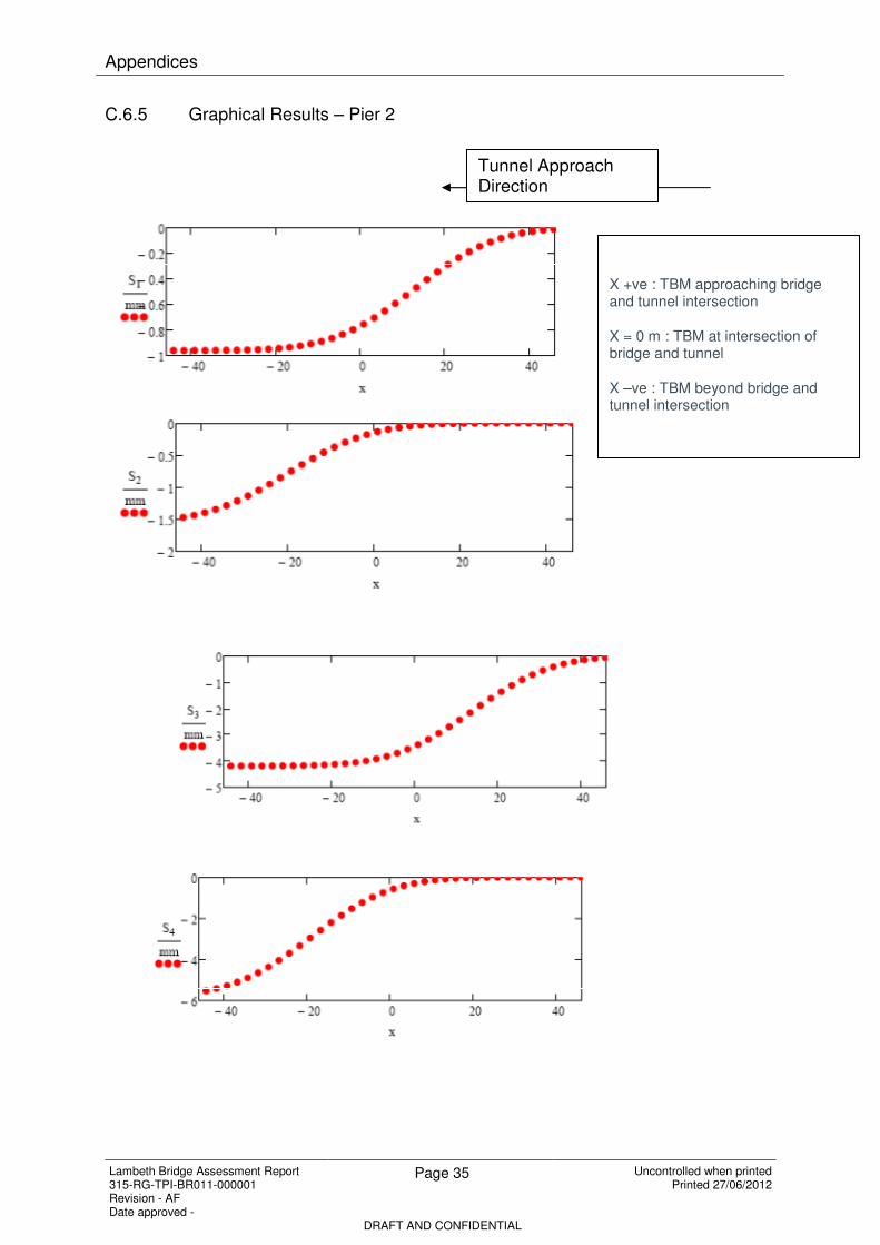
C.5.5 Using the corner points coordinates given; the centre point of each pier was calculated. The settlement of the pier corners was then calculated using the centre point of the pier, the angle of intersection between the bridge and the tunnel, and the advancing tunnel face. These are defined as S1, S2, S3 and S4, with the same numbering as the coordinates provided.

C.5.6 The horizontal movements in the transverse and longitudinal directions were calculated for the corners of each pier. An average value for each of these was taken, and was assumed to act from the centre of the pier. These new average horizontal transverse and longitudinal movements were then resolved in terms of movements parallel to the bridge decking (R1) and movements perpendicular to the bridge decking (R2). The values of R1 vary depending on the piers location in relation to the tunnel centreline. As the pier will tend to move towards the tunnel (due to the excavation of the soil), the direction of movement will be different either side of the tunnel, hence the change in sign. The value of R2 will decreases as the tunnel face progresses, and increases in the long term.

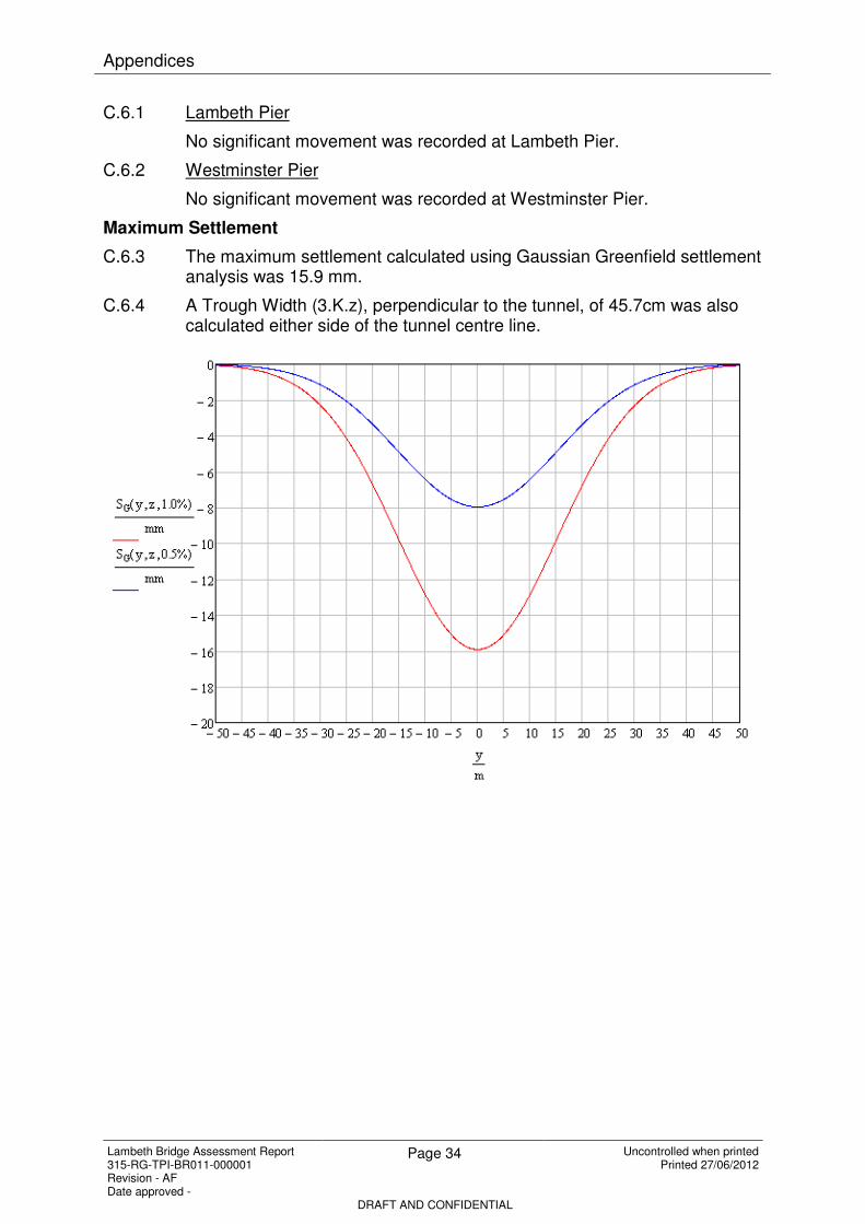
C.5.7 For the purpose of analysis significant movement has been defined as 1 mm. Piers which show movements less than 1mm are not considered significant and are omitted from the results section.

Figure C.3 R1, R2 in relation to approaching tunnel

xy

v

u

90

90

v

u

90

90

R1 = v cos ( - 90) - u sin ( - 90)

R2 = v sin ( - 90) + u cos ( - 90)

R1 = v cos ( - 90) - u sin ( - 90)

R2 = v sin ( - 90) + u cos ( - 90)

x

y

v

u

90

90

R1 = v cos (90 - ) + u sin (90 - )

R2 = -v sin (90 - ) + u cos (90 - )

R2

R1

v

u

90

90

R2

R1

R2

R1

R2

R1

R1 = v cos (90 - ) + u sin (90 - )

R2 = -v sin (90 - ) + u cos (90 - )

< 90°

> 90°

Appendices

Lambeth Bridge Assessment Report 315-RG-TPI-BR011-000001 Revision - AF Date approved -

Page 33 Uncontrolled when printed Printed 27/06/2012

DRAFT AND CONFIDENTIAL

C.6 Results

Pier 2

Pier 3

x (m)

S1 (mm)

S2 (mm)

S3 (mm)

S4 (mm)

R1 (mm)

R2 (mm)

S1 (mm)

S2 (mm)

S3 (mm)

S4 (mm)

R1 (mm)

R2 (mm)

65.00 0.00 0.00 0.00 0.00 0.00 0.00 -0.01 0.00 0.00 0.00 0.00 0.00 60.00 0.00 0.00 -0.01 0.00 0.00 0.00 -0.02 0.00 -0.01 0.00 -0.01 0.00 55.00 0.00 0.00 -0.02 0.00 0.00 0.00 -0.06 0.00 -0.02 0.00 -0.01 0.00 50.00 -0.01 0.00 -0.04 0.00 0.01 0.00 -0.14 0.00 -0.05 0.00 -0.03 -0.01 45.00 -0.02 0.00 -0.09 0.00 0.02 0.00 -0.30 0.00 -0.11 0.00 -0.07 -0.01 40.00 -0.04 0.00 -0.19 0.00 0.05 -0.01 -0.58 0.00 -0.20 0.00 -0.14 -0.03 35.00 -0.07 0.00 -0.36 0.00 0.10 -0.01 -1.02 0.00 -0.35 0.00 -0.24 -0.06 30.00 -0.13 0.00 -0.62 0.00 0.17 -0.04 -1.65 -0.01 -0.56 0.00 -0.39 -0.11 25.00 -0.21 0.00 -1.00 -0.01 0.28 -0.07 -2.46 -0.03 -0.81 -0.01 -0.57 -0.20 20.00 -0.31 -0.01 -1.47 -0.03 0.41 -0.13 -3.39 -0.07 -1.10 -0.02 -0.79 -0.32 15.00 -0.43 -0.02 -2.01 -0.08 0.58 -0.21 -4.35 -0.15 -1.40 -0.05 -1.02 -0.48 10.00 -0.56 -0.04 -2.55 -0.17 0.76 -0.30 -5.24 -0.30 -1.66 -0.09 -1.24 -0.65 5.00 -0.68 -0.08 -3.05 -0.35 0.95 -0.37 -5.99 -0.57 -1.88 -0.17 -1.47 -0.79 0.00 -0.78 -0.15 -3.46 -0.64 1.14 -0.41 -6.55 -0.96 -2.03 -0.28 -1.69 -0.89

-5.00 -0.85 -0.26 -3.77 -1.07 1.33 -0.40 -6.92 -1.49 -2.14 -0.43 -1.91 -0.91 -10.00 -0.90 -0.41 -3.97 -1.66 1.52 -0.33 -7.15 -2.15 -2.20 -0.60 -2.13 -0.86 -15.00 -0.93 -0.59 -4.09 -2.35 1.72 -0.22 -7.28 -2.86 -2.23 -0.79 -2.35 -0.76 -20.00 -0.95 -0.79 -4.16 -3.11 1.91 -0.09 -7.34 -3.57 -2.25 -0.97 -2.56 -0.64 -25.00 -0.96 -0.99 -4.19 -3.85 2.09 0.02 -7.37 -4.19 -2.26 -1.13 -2.73 -0.52 -30.00 -0.96 -1.17 -4.20 -4.49 2.25 0.11 -7.38 -4.69 -2.26 -1.25 -2.87 -0.43 -35.00 -0.97 -1.32 -4.21 -5.00 2.38 0.18 -7.38 -5.05 -2.26 -1.34 -2.96 -0.37 -40.00 -0.97 -1.42 -4.21 -5.36 2.47 0.22 -7.38 -5.28 -2.26 -1.39 -3.02 -0.34 -45.00 -0.97 -1.49 -4.21 -5.58 2.52 0.24 -7.38 -5.41 -2.26 -1.42 -3.06 -0.32 -50.00 -0.97 -1.53 -4.21 -5.71 2.56 0.25 -7.38 -5.48 -2.26 -1.44 -3.08 -0.31 -55.00 -0.97 -1.55 -4.21 -5.78 2.57 0.25 -7.38 -5.52 -2.26 -1.44 -3.08 -0.31 -60.00 -0.97 -1.56 -4.21 -5.81 2.58 0.26 -7.38 -5.53 -2.26 -1.45 -3.09 -0.31 -65.00 -0.97 -1.56 -4.21 -5.82 2.58 0.26 -7.38 -5.54 -2.26 -1.45 -3.09 -0.31

Appendices

Lambeth Bridge Assessment Report 315-RG-TPI-BR011-000001 Revision - AF Date approved -

Page 34 Uncontrolled when printed Printed 27/06/2012

DRAFT AND CONFIDENTIAL

C.6.1 Lambeth Pier

No significant movement was recorded at Lambeth Pier.

C.6.2 Westminster Pier

No significant movement was recorded at Westminster Pier.

Maximum Settlement

C.6.3 The maximum settlement calculated using Gaussian Greenfield settlement analysis was 15.9 mm.

C.6.4 A Trough Width (3.K.z), perpendicular to the tunnel, of 45.7cm was also calculated either side of the tunnel centre line.

Appendices

Lambeth Bridge Assessment Report 315-RG-TPI-BR011-000001 Revision - AF Date approved -

Page 35 Uncontrolled when printed Printed 27/06/2012

DRAFT AND CONFIDENTIAL

C.6.5 Graphical Results – Pier 2

Tunnel Approach Direction

X +ve : TBM approaching bridge and tunnel intersection

X = 0 m : TBM at intersection of bridge and tunnel

X –ve : TBM beyond bridge and tunnel intersection

Appendices

Lambeth Bridge Assessment Report 315-RG-TPI-BR011-000001 Revision - AF Date approved -

Page 36 Uncontrolled when printed Printed 27/06/2012

DRAFT AND CONFIDENTIAL

Appendices

Lambeth Bridge Assessment Report 315-RG-TPI-BR011-000001 Revision - AF Date approved -

Page 37 Uncontrolled when printed Printed 27/06/2012

DRAFT AND CONFIDENTIAL

C.6.6 Graphical Results – Pier 3

Appendices

Lambeth Bridge Assessment Report 315-RG-TPI-BR011-000001 Revision - AF Date approved -

Page 38 Uncontrolled when printed Printed 27/06/2012

DRAFT AND CONFIDENTIAL

C.7 References

1. Settlements above Tunnels in United Kingdom – Their magnitude and

Prediction – O’Reilly, P and New, B.M., Tunnelling 1982, pp173-181, 1982

2. Tunnelling in Soil – Attewell & Yeates 1986

3. Design Standard and Guidance – Thames Water (Document Number 100-PS-

DES-00000-000008, 4th May, 2010)

Appendices

Lambeth Bridge Assessment Report 315-RG-TPI-BR011-000001 Revision - AF Date approved -

Page 39 Uncontrolled when printed Printed 27/06/2012

DRAFT AND CONFIDENTIAL

Appendix D – Settlement Summary

Figure D.1 Axis System relative to bridge deck

Centre Span Settlements

DX

(mm)

DY

(mm)

DZ

(mm)

RX

(deg) RY (deg) RZ (deg)

Maximum Settlement -0.2 1.2 -0.1 0 0.1 0

Minimum Settlement -1.5 -4 -5.6 0 -0.1 0

Intermediate Span Settlements

DX

(mm)

DY

(mm)

DZ

(mm)

RX

(deg) RY (deg) RZ (deg)

Maximum Settlement 4.5 0.8 -0.1 0 0 0

Minimum Settlement 0.2 -1.2 -2.5 0 0 0

DX (mm)

DY (mm)

DZ (mm)

RX (deg)

RY (deg)

RZ (deg)

Maximum Settlement 4.5 1.2 -0.1 0 0.1 0

Minimum Settlement -1.5 -4 -5.6 0 -0.1 0

Appendices

Lambeth Bridge Assessment Report 315-RG-TPI-BR011-000001 Revision - AF Date approved -

Page 40 Uncontrolled when printed Printed 27/06/2012

DRAFT AND CONFIDENTIAL

Appendix E – Cat II Check Results & Comparison

Inner Rib Top w 19mm Plate FX (kN) FY (kN) FZ (kN) MX (kNm) MY (kNm) MZ (kNm) FX + MY

FX (kN) FY (kN) FZ (kN) FX (kN) FY (kN) FZ (kN) MX (kNm) MY (kNm) MZ (kNm) MX (kNm) MY (kNm) MZ (kNm) Previous Assessment Loads 2103.6 - 41.3 - 26.0 -

Inner Rib Top w 19mm Plate (Intermediate Span) 132.9 1.2 47.3 0.9 0.9 55.6 0.0 39.4 2.7 0.0 48.5 3.3 Previous Assessment Resistance 3867.0 - 1068.0 - 617.9 - 0.6

Inner Rib Top w 19mm Plate (Central Span) 0.0 2.9 95.4 235.2 2.8 36.8 0.0 71.1 4.1 0.0 17.2 4.0 Additonal Load 282.2 - 95.4 - 85.3 -

Max 132.9 2.9 95.4 235.2 2.8 55.6 0.0 71.1 4.1 0.0 48.5 4.0 % Increase 11.8% - 69.8% - 76.6% - 26.48%

1.2*Max 159.5 3.5 114.5 282.2 3.3 66.7 0.1 85.3 5.0 0.1 58.2 4.7 Total Load 2385.8 - 136.7 - 111.3 - 0.80

Usage 0.62 - 0.13 - 0.18 - 0.80

- - -

Inner Rib Top w 19mm Plate FX (kN) FY (kN) FZ (kN) MX (kNm) MY (kNm) MZ (kNm) FX + MY

Previous Assessment Loads 2103.6 - 41.3 - 26.0 -

Previous Assessment Resistance 3867.0 - 1068.0 - 617.9 - 0.6

Additonal Load 196.6 - 5.5 - 9.7 -

% Increase 8.5% - 11.8% - 27.2% - 10.20%

Total Load 2300.2 - 46.8 - 35.7 - 0.65

Usage 0.59 - 0.04 - 0.06 - 0.65

- - -

Additional Load Variance 30% - 94% - 89% - -

Usage Variance 4% - 66% - 68% - 18%

Inner Rib Top w 19mm & 15.9mm Plates FX (kN) FY (kN) FZ (kN) MX (kNm) MY (kNm) MZ (kNm) FX + MY

FX (kN) FY (kN) FZ (kN) FX (kN) FY (kN) FZ (kN) MX (kNm) MY (kNm) MZ (kNm) MX (kNm) MY (kNm) MZ (kNm) Previous Assessment Loads 2998.7 - 19.4 - 10.3 -

Inner Rib Top w 19mm & 15.9mm Plates (Intermediate Span) N/A N/A N/A N/A N/A N/A N/A N/A N/A N/A N/A N/A Previous Assessment Resistance 4786.0 - 1068.0 - 617.9 - 0.6

Inner Rib Top w 19mm & 15.9mm Plates (Central Span) -17.8 1.2 -0.7 260.8 1.0 15.7 0.0 -0.2 1.6 0.0 62.4 1.5 Additonal Load 312.9 - 18.9 - 74.9 -

Max -17.8 1.2 -0.7 260.8 1.0 15.7 0.0 -0.2 1.6 0.0 62.4 1.5 % Increase 9.4% - 49.3% - 87.9% - 22.48%

1.2*Max -21.3 1.4 -0.9 312.9 1.1 18.9 0.0 -0.2 1.9 0.0 74.9 1.7 Total Load 3311.6 - 38.3 - 85.2 - 0.83

Usage 0.69 - 0.04 - 0.14 - 0.83

- - -

Inner Rib Top w 19mm Plate FX (kN) FY (kN) FZ (kN) MX (kNm) MY (kNm) MZ (kNm) FX + MY

Previous Assessment Loads 2998.7 - 19.4 - 10.3 - 0.0

Previous Assessment Resistance 4786.0 - 1068.0 - 617.9 - 0.6

Additonal Load 232.0 - 4.4 - 9.8 -

% Increase 7.2% - 18.6% - 48.9% - 9.10%

Total Load 3230.7 - 23.8 - 20.1 - 0.71

Usage 0.68 - 0.02 - 0.03 - 0.71

- - -

Additional Load Variance 26% - 77% - 87% - -

Usage Variance 2% - 38% - 76% - 15%

Inner Rib Bottom Triple Web FX (kN) FY (kN) FZ (kN) MX (kNm) MY (kNm) MZ (kNm)

FX (kN) FY (kN) FZ (kN) FX (kN) FY (kN) FZ (kN) MX (kNm) MY (kNm) MZ (kNm) MX (kNm) MY (kNm) MZ (kNm) Previous Assessment Loads 5422.5 - 25.2 - 52.1 -

Inner Rib Bottom Triple Web (Intermediate Span) N/A N/A N/A N/A N/A N/A N/A N/A N/A N/A N/A N/A Previous Assessment Resistance 8678.0 - 939.0 - 2106.4 -

Inner Rib Bottom Triple Web (Central Span) 79.2 2.8 19.0 -0.3 1.5 -1.2 0.0 -3.6 7.2 0.0 7.3 0.3 Additonal Load 95.0 - 22.7 - 8.7 -

Max 79.2 2.8 19.0 -0.3 1.5 -1.2 0.0 -3.6 7.2 0.0 7.3 0.3 % Increase 1.7% - 47.4% - 14.3% -

1.2*Max 95.0 3.4 22.7 -0.4 1.8 -1.4 0.0 -4.3 8.6 0.0 8.7 0.3 Total Load 5517.5 - 47.9 - 60.8 -

Usage 0.64 - 0.05 - 0.03 -

- - -

Inner Rib Bottom Single Web FX (kN) FY (kN) FZ (kN) MX (kNm) MY (kNm) MZ (kNm) FX + MY

FX (kN) FY (kN) FZ (kN) FX (kN) FY (kN) FZ (kN) MX (kNm) MY (kNm) MZ (kNm) MX (kNm) MY (kNm) MZ (kNm) Previous Assessment Loads 5422.5 - 25.2 - 52.1 -

Inner Rib Bottom Single Web (Intermediate Span) -0.1 1.5 46.2 161.9 2.9 48.7 0.1 163.1 3.7 0.1 11.7 4.1 Previous Assessment Resistance 8678.0 - 939.0 - 2106.4 - 0.6

Inner Rib Bottom Single Web (Central Span) 312.8 0.9 3.5 -0.4 0.8 57.2 0.0 1.8 1.3 0.0 237.8 1.1 Additonal Load 375.4 - 55.4 - 285.4 -

Max 312.8 1.5 46.2 161.9 2.9 57.2 0.1 163.1 3.7 0.1 237.8 4.1 % Increase 6.5% - 68.7% - 84.6% - 21.58%

1.2*Max 375.4 1.8 55.4 194.3 3.5 68.6 0.1 195.7 4.5 0.1 285.4 4.9 Total Load 5797.9 - 80.6 - 337.5 - 0.83

Usage 0.67 - 0.09 - 0.16 - 0.83

- - -

Inner Rib Bottom Single Web FX (kN) FY (kN) FZ (kN) MX (kNm) MY (kNm) MZ (kNm) FX + MY

Previous Assessment Loads 5422.5 - 25.2 - 52.1 -

Previous Assessment Resistance 8678.0 - 939.0 - 2106.4 - 0.6

Additonal Load 253.9 - 55.1 - 144.2 -

% Increase 4.5% - 68.6% - 73.5% - 13.08%

Total Load 5676.4 - 80.3 - 196.3 - 0.75

Usage 0.65 - 0.09 - 0.09 - 0.75

- - -

Additional Load Variance 32% - 1% - 49% - -

Usage Variance 2% - 0% - 42% - 10%

End 1 End 2 End 1 End 2

End 1 End 2 End 1 End 2

Note that resistances for FZ and

MY were not calculated in the

previous assessment but have

been calculated here for the

purpose of analysis.

Resistances for FZ and MY

were not calculated in the

previous assessment. The

resistances calculated for the

"Inner Rib Top w 19mm Plate"

have been used as a

conservative estimate.

Resistances for FZ and MY have

been calculated as only loading

was considered in the previous

assessment.

The previous assessment does not consider

loading in this member. The loads and

resistances for the "Inner Rib Bottom Single

Web" have been used as a conservative

estimate.

1

End 1 End 2 End 1 End 2

2

4

End 1 End 2 End 1 End 2

3

Note that resistances for FZ and

MY were not calculated in the

previous assessment but have

been calculated here for the

purpose of analysis.

Resistances for FZ and MY

were not calculated in the

previous assessment. The

resistances calculated for the

"Inner Rib Top w 19mm Plate"

have been used as a

conservative estimate.

Section 1 Check

Section 2 Check

Resistances for FZ and MY have

been calculated as only loading

was considered in the previous

assessment.Section 4 Check

Appendices

Lambeth Bridge Assessment Report 315-RG-TPI-BR011-000001 Revision - AF Date approved -

Page 41 Uncontrolled when printed Printed 27/06/2012

DRAFT AND CONFIDENTIAL

Channels 10" x 3" FX (kN) FY (kN) FZ (kN) MX (kNm) MY (kNm) MZ (kNm)

FX (kN) FY (kN) FZ (kN) FX (kN) FY (kN) FZ (kN) MX (kNm) MY (kNm) MZ (kNm) MX (kNm) MY (kNm) MZ (kNm) Previous Assessment Loads 324.2 - - - - -

Channels 10" x 3" (Intermediate Span) -0.5 0.0 1.4 32.8 0.0 1.0 0.0 1.8 0.1 0.0 3.2 0.1 Previous Assessment Resistance 1006.0 - - - - -

Channels 10" x 3" (Central Span) 53.3 0.0 1.1 -0.9 0.0 1.7 0.0 6.1 0.1 0.0 2.6 0.1 Additonal Load 63.9 - - - - -

Max 53.3 0.0 1.4 32.8 0.0 1.7 0.0 6.1 0.1 0.0 3.2 0.1 % Increase 16.5% - - - - -

1.2*Max 63.9 0.1 1.7 39.3 0.1 2.1 0.0 7.3 0.1 0.0 3.8 0.2 Total Load 388.1 - - - - -

Usage 0.39 - - - - -

- - - - -

Channels 10" x 3" FX (kN) FY (kN) FZ (kN) MX (kNm) MY (kNm) MZ (kNm)

Previous Assessment Loads 324.2 - - - - -

Previous Assessment Resistance 1006.0 - - - - -

Additonal Load 45.6 - - - - -

% Increase 12.3% - - - - -

Total Load 369.8 - - - - -

Usage 0.37 - - - - -

- - - - -

Additional Load Variance 29% - - - - -

Usage Variance 5% - - - - -

Channels 10" x 3.5" FX (kN) FY (kN) FZ (kN) MX (kNm) MY (kNm) MZ (kNm)

FX (kN) FY (kN) FZ (kN) FX (kN) FY (kN) FZ (kN) MX (kNm) MY (kNm) MZ (kNm) MX (kNm) MY (kNm) MZ (kNm) Previous Assessment Loads 684.9 - - - - -

Channels 10" x 3.5" (Intermediate Span) -1.4 0.0 0.7 56.0 0.1 0.8 0.0 1.0 0.1 0.0 1.4 0.1 Previous Assessment Resistance 1281.0 - - - - -

Channels 10" x 3.5" (Central Span) 90.9 0.1 0.7 -4.2 0.1 0.0 0.0 -0.1 0.1 0.0 0.2 0.2 Additonal Load 109.0 - - - - -

Max 90.9 0.1 0.7 56.0 0.1 0.8 0.0 1.0 0.1 0.0 1.4 0.2 % Increase 13.7% - - - - -

1.2*Max 109.0 0.1 0.9 67.2 0.1 1.0 0.0 1.2 0.2 0.0 1.7 0.2 Total Load 793.9 - - - - -

Usage 0.62 - - - - -

- - - - -

Channels 10" x 3.5" FX (kN) FY (kN) FZ (kN) MX (kNm) MY (kNm) MZ (kNm)

Previous Assessment Loads 684.9 - - - - -

Previous Assessment Resistance 1281.0 - - - - -

Additonal Load 77.0 - - - - -

% Increase 10.1% - - - - -

Total Load 761.9 - - - - -

Usage 0.59 - - - - -

- - - - -

Additional Load Variance 29% - - - - -

Usage Variance 4% - - - - -

Inner Rib Triple Web FX (kN) FY (kN) FZ (kN) MX (kNm) MY (kNm) MZ (kNm) FX + MY

FX (kN) FY (kN) FZ (kN) FX (kN) FY (kN) FZ (kN) MX (kNm) MY (kNm) MZ (kNm) MX (kNm) MY (kNm) MZ (kNm) Previous Assessment Loads 6121.4 - 207.3 - 1878.1 -

Inner Rib Triple Web (Intermediate Span) -0.7 2.0 8.6 44.2 1.3 6.8 0.7 221.3 4.8 0.7 -8.5 5.0 Previous Assessment Resistance 23122.0 - 6009.0 - 6809.0 - 0.5

Inner Rib Triple Web (Central Span) 64.3 0.4 3.5 -1.1 0.0 13.3 0.0 -20.7 1.0 0.0 336.4 0.4 Additonal Load 77.1 - 15.9 - 403.7 -

Max 64.3 2.0 8.6 44.2 1.3 13.3 0.7 221.3 4.8 0.7 336.4 5.0 % Increase 1.2% - 7.1% - 5.9% - 10.38%

1.2*Max 77.1 2.4 10.3 53.0 1.6 15.9 0.9 265.6 5.8 0.9 403.7 6.0 Total Load 6198.5 - 223.2 - 2281.8 - 0.60

Usage 0.27 - 0.04 - 0.34 - 0.60

- - -

Inner Rib Triple Web FX (kN) FY (kN) FZ (kN) MX (kNm) MY (kNm) MZ (kNm) FX + MY

Previous Assessment Loads 6121.4 - 207.3 - 1878.1 -

Previous Assessment Resistance 23122.0 - 6009.0 - 6809.0 - 0.5

Additonal Load 48.6 - 13.4 - 198.1 -

% Increase 0.8% - 6.1% - 2.9% - 5.46%

Total Load 6170.0 - 220.7 - 2076.2 - 0.57

Usage 0.27 - 0.04 - 0.30 - 0.57

- - -

Additional Load Variance 37% - 15% - 51% - -

Usage Variance 0% - 1% - 9% - 5%

Outer Arch FX (kN) FY (kN) FZ (kN) MX (kNm) MY (kNm) MZ (kNm) FX + MY

FX (kN) FY (kN) FZ (kN) FX (kN) FY (kN) FZ (kN) MX (kNm) MY (kNm) MZ (kNm) MX (kNm) MY (kNm) MZ (kNm) Previous Assessment Loads 5017.5 - 169.9 - 1539.4 -

Outer Arch (Intermediate Span) 0.2 2.0 34.6 -5.4 2.0 35.4 0.2 207.3 5.8 0.2 0.1 5.7 Previous Assessment Resistance 13355.0 - 1561.0 - 4079.0 - 0.8

Outer Arch (Central Span) 168.8 3.6 7.0 88.3 2.0 35.4 0.0 -0.3 9.8 0.0 348.0 1.9 Additonal Load 202.5 - 42.5 - 417.6 -

Max 168.8 3.6 34.6 88.3 2.0 35.4 0.2 207.3 9.8 0.2 348.0 5.7 % Increase 3.9% - 20.0% - 21.3% - 13.50%

1.2*Max 202.5 4.3 41.5 105.9 2.4 42.5 0.3 248.7 11.8 0.3 417.6 6.8 Total Load 5220.0 - 212.4 - 1957.0 - 0.87

Usage 0.39 - 0.14 - 0.48 - 0.87

- - -

Outer Arch FX (kN) FY (kN) FZ (kN) MX (kNm) MY (kNm) MZ (kNm) FX + MY

Previous Assessment Loads 5017.5 - 169.9 - 1539.4 -

Previous Assessment Resistance 13355.0 - 1561.0 - 4079.0 - 0.8

Additonal Load 162.7 - 40.3 - 397.1 - -

% Increase 3.1% - 19.2% - 20.5% - 12.70%

Total Load 5180.2 - 210.2 - 1936.5 - 0.86

Usage 0.39 - 0.13 - 0.47 - 0.86

- - -

Additional Load Variance 20% - 5% - 5% - -

Usage Variance 1% - 1% - 1% - 1%

9

8

End 1 End 2 End 1 End 2

Section 9 Check

End 1 End 2 End 1 End 2

6

End 1 End 2 End 1 End 2

5

End 1 End 2 End 1 End 2

Note that loading is negligible other than for

FX

Note that loading is negligible other than for

FX

The previous assessment does

not consider loading in this

member. Therefore, the loading

used in the previous assessment

for the "Outer Arch" has been

factored up and resitances have

been calculated.

Note that loading is negligible other than for

FX

Section 5 Check

Section 6 Check

Note that loading is negligible other than for

FX

The previous assessment does

not consider loading in this

member. Therefore, the loading

used in the previous assessment

for the "Outer Arch" has been

factored up and resitances have

been calculated.

Section 8 Check

Appendices

Lambeth Bridge Assessment Report 315-RG-TPI-BR011-000001 Revision - AF Date approved -

Page 42 Uncontrolled when printed Printed 27/06/2012

DRAFT AND CONFIDENTIAL

Outer Rib Top FX (kN) FY (kN) FZ (kN) MX (kNm) MY (kNm) MZ (kNm)

FX (kN) FY (kN) FZ (kN) FX (kN) FY (kN) FZ (kN) MX (kNm) MY (kNm) MZ (kNm) MX (kNm) MY (kNm) MZ (kNm) Previous Assessment Loads 2103.6 - - - - -

Outer Rib Top (Intermediate Span) 20.1 0.5 3.3 0.0 0.5 2.0 0.0 1.2 1.3 0.0 1.8 1.6 Previous Assessment Resistance 3189.0 - - - - -

Outer Rib Top (Central Span) 0.0 1.1 3.6 53.3 1.1 1.8 0.0 2.3 1.5 0.0 1.9 1.7 Additonal Load 64.0 - - - - -

Max 20.1 1.1 3.6 53.3 1.1 2.0 0.0 2.3 1.5 0.0 1.9 1.7 % Increase 2.0% - - - - -

1.2*Max 24.1 1.3 4.3 64.0 1.3 2.4 0.0 2.8 1.8 0.0 2.3 2.0 Total Load 2167.6 - - - - -

Usage 0.68 - - - - -

- - - - -

Outer Rib Top FX (kN) FY (kN) FZ (kN) MX (kNm) MY (kNm) MZ (kNm)

Previous Assessment Loads 2103.6 - - - - -

Previous Assessment Resistance 3189.0 - - - - -

Additonal Load 28.4 - - - - -

% Increase 0.9% - - - - -

Total Load 2132.0 - - - - -

Usage 0.67 - - - - -

- - - - -

Additional Load Variance 56% - - - - -

Usage Variance 2% - - - - -

Diagonal Bracing Horizontal FX (kN) FY (kN) FZ (kN) MX (kNm) MY (kNm) MZ (kNm)

FX (kN) FY (kN) FZ (kN) FX (kN) FY (kN) FZ (kN) MX (kNm) MY (kNm) MZ (kNm) MX (kNm) MY (kNm) MZ (kNm) Previous Assessment Loads - - - - -

Diagonal Bracing Horizontal (Intermediate Span) 8.7 0.0 0.0 10.2 0.0 0.0 0.0 0.0 0.0 0.0 0.0 0.0 Previous Assessment Resistance 265.0 - - - - -

Diagomal Bracing Horizontal (Central Span) 9.7 0.0 0.0 8.2 0.0 0.0 0.0 0.0 0.0 0.0 0.0 0.0 Additonal Load 11.6 - - - - -

Max 9.7 0.0 0.0 10.2 0.0 0.0 0.0 0.0 0.0 0.0 0.0 0.0 % Increase 4.4% - - - - -

1.2*Max 11.6 0.0 0.0 12.2 0.0 0.0 0.0 0.0 0.1 0.0 0.0 0.0 Total Load 11.6 - - - - -

Usage 0.04 - - - - -

- - - - -

Diagonal Bracing Horizontal FX (kN) FY (kN) FZ (kN) MX (kNm) MY (kNm) MZ (kNm)

Previous Assessment Loads - - - - -

Previous Assessment Resistance 265.0 - - - - -

Additonal Load 67.1 - - - - -

% Increase 25.3% - - - - -

Total Load 67.1 - - - - -

Usage 0.25 - - - - -

- - - - -

Additional Load Variance 83% - - - - -

Usage Variance 83% - - - - -

Diagonal Bracing Vertical FX (kN) FY (kN) FZ (kN) MX (kNm) MY (kNm) MZ (kNm)

FX (kN) FY (kN) FZ (kN) FX (kN) FY (kN) FZ (kN) MX (kNm) MY (kNm) MZ (kNm) MX (kNm) MY (kNm) MZ (kNm) Previous Assessment Loads - - - - -

Diagonal Bracing Vertical (Intermediate Span) 5.4 0.1 0.0 3.8 0.1 0.0 0.0 0.0 0.1 0.0 0.0 0.1 Previous Assessment Resistance 56.7 - - - - -

Diagonal Bracing Vertical (Central Span) 6.5 0.0 0.0 8.3 0.0 0.0 0.0 0.0 0.0 0.0 0.0 0.0 Additonal Load 10.0 - - - - -

Max 6.5 0.1 0.0 8.3 0.1 0.0 0.0 0.0 0.1 0.0 0.0 0.1 % Increase 17.6% - - - - -

1.2*Max 7.8 0.1 0.0 10.0 0.1 0.0 0.0 0.0 0.1 0.0 0.0 0.1 Total Load 10.0 - - - - -

Usage 0.18 - - - - -

- - - - -

Diagonal Bracing Vertical FX (kN) FY (kN) FZ (kN) MX (kNm) MY (kNm) MZ (kNm)

Previous Assessment Loads - - - - -

Previous Assessment Resistance 56.7 - - - - -

Additonal Load 13.2 - - - - -

% Increase 23.3% - - - - -

Total Load 13.2 - - - - -

Usage 0.23 - - - - -

- - - - -

Additional Load Variance 24% - - - - -

Usage Variance 24% - - - - -

Verticals 6" x 6" x 0.5" FX (kN) FY (kN) FZ (kN) MX (kNm) MY (kNm) MZ (kNm)

FX (kN) FY (kN) FZ (kN) FX (kN) FY (kN) FZ (kN) MX (kNm) MY (kNm) MZ (kNm) MX (kNm) MY (kNm) MZ (kNm) Previous Assessment Loads 650.5 - - - - -

Verticals 6" x 6" x 0.5" (Intermediate Span) 83.6 0.3 1.1 -1.1 0.2 0.9 0.0 3.3 0.5 0.0 1.6 0.4 Previous Assessment Resistance 1909.0 - - - - -

Verticals 6" x 6" x 0.5" (Central Span) -8.7 0.3 1.5 134.9 0.2 1.4 0.0 6.0 0.4 0.0 2.2 0.6 Additonal Load 100.3 - - - - -

Max 83.6 0.3 1.5 134.9 0.2 1.4 0.0 6.0 0.5 0.0 2.2 0.6 % Increase 13.4% - - - - -

1.2*Max 100.3 0.3 1.8 161.8 0.3 1.7 0.0 7.2 0.5 0.1 2.7 0.7 Total Load 750.8 - - - - -

Usage 0.39 - - - - -

- - - - -

Verticals 6" x 6" x 0.5" FX (kN) FY (kN) FZ (kN) MX (kNm) MY (kNm) MZ (kNm)

Previous Assessment Loads 650.5 - - - - -

Previous Assessment Resistance 1909.0 - - - - -

Additonal Load 71.5 - - - - -

% Increase 9.9% - - - - -

Total Load 722.0 - - - - -

Usage 0.38 - - - - -

- - - - -

Additional Load Variance 29% - - - - -

Usage Variance 4% - - - - -

13

12

End 1 End 2 End 1 End 2

Section 13 Check

11

End 1 End 2 End 1 End 2

10

End 1 End 2 End 1 End 2

End 1 End 2 End 1 End 2

The previous assessment does not consider

loading in this member. Therefore the

previous loading and resistance from the

3.5" x 3.5" x 0.5" verticals has been

assumed.

The previous assessment does not consider

loading in this member. Therefore the

loading used for "Inner Rib Top w 19mm

Plate" has been used as an estimate.

The previous assessment does not consider

loading in this member. Therefore this

calculation just considers percentage

increase in load compared with overall

resistance

The previous assessment does not consider

loading in this member. Therefore this

calculation just considers percentage

increase in load compared with overall

resistance

The previous assessment does not consider

loading in this member. Therefore the

loading used for "Inner Rib Top w 19mm

Plate" has been used as an estimate.

The previous assessment does not consider

loading in this member. Therefore this

calculation just considers percentage

increase in load compared with overall

resistance

The previous assessment does not consider

loading in this member. Therefore the

previous loading and resistance from the

3.5" x 3.5" x 0.5" verticals has been

assumed.

Section 10 Check

Section 11 Check

The previous assessment does not consider

loading in this member. Therefore this

calculation just considers percentage

increase in load compared with overall

resistance

Section 12 Check

Appendices

Lambeth Bridge Assessment Report 315-RG-TPI-BR011-000001 Revision - AF Date approved -

Page 43 Uncontrolled when printed Printed 27/06/2012

DRAFT AND CONFIDENTIAL

Verticals 4" x 4" x 0.5" FX (kN) FY (kN) FZ (kN) MX (kNm) MY (kNm) MZ (kNm)

FX (kN) FY (kN) FZ (kN) FX (kN) FY (kN) FZ (kN) MX (kNm) MY (kNm) MZ (kNm) MX (kNm) MY (kNm) MZ (kNm) Previous Assessment Loads 650.5 - - - - -

Verticals 4" x 4" x 0.5" (Intermediate Span) 19.1 0.1 0.3 0.1 0.0 0.0 0.0 0.0 0.1 0.0 0.0 0.0 Previous Assessment Resistance 1909.0 - - - - -

Verticals 4" x 4" x 0.5" (Central Span) 7.1 0.0 0.4 2.4 0.0 0.4 0.0 1.1 0.1 0.0 0.8 0.1 Additonal Load 22.9 - - - - -

Max 19.1 0.1 0.4 2.4 0.0 0.4 0.0 1.1 0.1 0.0 0.8 0.1 % Increase 3.4% - - - - -

1.2*Max 22.9 0.1 0.5 2.9 0.1 0.5 0.0 1.4 0.1 0.0 1.0 0.1 Total Load 673.4 - - - - -

Usage 0.35 - - - - -

- - - - -

Verticals 4" x 4" x 0.5" FX (kN) FY (kN) FZ (kN) MX (kNm) MY (kNm) MZ (kNm)

Previous Assessment Loads 650.5 - - - - -

Previous Assessment Resistance 1909.0 - - - - -

Additonal Load 439.2 - - - - -

% Increase 40.3% - - - - -

Total Load 1089.7 - - - - -

Usage 0.57 - - - - -

- - - - -

Additional Load Variance 95% - - - - -

Usage Variance 38% - - - - -

Verticals 3.5" x 3.5" x 0.5" FX (kN) FY (kN) FZ (kN) MX (kNm) MY (kNm) MZ (kNm)

FX (kN) FY (kN) FZ (kN) FX (kN) FY (kN) FZ (kN) MX (kNm) MY (kNm) MZ (kNm) MX (kNm) MY (kNm) MZ (kNm) Previous Assessment Loads 650.5 - - - -

Verticals 3.5" x 3.5" x 0.5" (Intermediate Span) 25.1 1.1 7.6 4.2 1.1 5.9 0.0 3.3 0.5 0.0 3.4 0.6 Previous Assessment Resistance 1909.0 - 416.0 - - -

Verticals 3.5" x 3.5" x 0.5" (Central Span) -0.1 4.7 18.3 40.5 4.6 18.3 0.0 5.1 1.4 0.0 5.4 1.4 Additonal Load 48.6 - 22.0 - - -

Max 25.1 4.7 18.3 40.5 4.6 18.3 0.0 5.1 1.4 0.0 5.4 1.4 % Increase 7.0% - 5.3% - - -

1.2*Max 30.1 5.7 21.9 48.6 5.5 22.0 0.0 6.2 1.6 0.0 6.5 1.6 Total Load 699.1 - 22.0 - - -

Usage 0.37 - 0.05 - - -

- - - -

Verticals 3.5" x 3.5" x 0.5" FX (kN) FY (kN) FZ (kN) MX (kNm) MY (kNm) MZ (kNm)

Previous Assessment Loads 650.5 - - - -

Previous Assessment Resistance 1909.0 - 416.0 - - -

Additonal Load 33.1 - 36.1 - - -

% Increase 4.8% - 8.7% - - -

Total Load 683.6 - 36.1 - - -

Usage 0.36 - 0.09 - - -

- - - -

Additional Load Variance 32% - - - - -

Usage Variance 2% - - - - -

Transverse Beams 13" Web FX (kN) FY (kN) FZ (kN) MX (kNm) MY (kNm) MZ (kNm)

FX (kN) FY (kN) FZ (kN) FX (kN) FY (kN) FZ (kN) MX (kNm) MY (kNm) MZ (kNm) MX (kNm) MY (kNm) MZ (kNm) Previous Assessment Loads - - - 114.4 -

Transverse Beams 13" Web (Intermediate Span) 9.0 0.7 2.1 10.6 1.1 1.0 0.0 1.7 0.7 0.0 1.2 0.7 Previous Assessment Resistance 1619.0 - - - 191.0 -

Transverse Beams 13" Web (Central Span) 18.3 2.0 1.4 14.4 2.2 2.1 0.0 3.0 2.1 0.0 3.7 2.1 Additonal Load 21.9 - - - 4.4 -

Max 18.3 2.0 2.1 14.4 2.2 2.1 0.0 3.0 2.1 0.0 3.7 2.1 % Increase 1.4% - - - 3.7% -

1.2*Max 21.9 2.4 2.5 17.3 2.6 2.5 0.0 3.6 2.5 0.0 4.4 2.5 Total Load 21.9 - - - 118.8 -

Usage 0.01 - - - 0.62 -

- - - -

Transverse Beams 13" Web FX (kN) FY (kN) FZ (kN) MX (kNm) MY (kNm) MZ (kNm)

Previous Assessment Loads - - - - -

Previous Assessment Resistance 1619.0 - - - - -

Additonal Load 600.4 - - - - -

% Increase 37.1% - - - - -

Total Load 600.4 - - - - -

Usage 0.37 - - - - -

- - - - -

Additional Load Variance 96% - - - - -

Usage Variance 96% - - - - -

Note:

17

End 1 End 2 End 1 End 2

15

For Fx: end 1, tension is negative and compression is positive. For End 2,

the signs are reversed.

14

End 1 End 2 End 1 End 2

Section 14 Check

End 1 End 2 End 1 End 2

The previous assessment does not consider

loading in this member. Therefore the

previous loading and resistance from the

3.5" x 3.5" x 0.5" verticals has been

assumed.

Note that neither loading or resistance were

considered/calculated in the previous

assessment for FZ. The resistance has

been calculated here and the calculation

therefore considers percentage increase in

load compared with overall resistance.

Section 15 Check

Loading in the FX direction was not

considered in the previous assessment. The

resistance has been calculated and the

percentage increase in load compared with

overall resitance has been considered.

Section 17 Check

Loading in the FX direction was not

considered in the previous assessment. The

resistance has been calculated and the

percentage increase in load compared with

overall resitance has been considered.

Note that neither loading or resistance were

considered/calculated in the previous

assessment for FZ. The resistance has

been calculated here and the calculation

therefore considers percentage increase in

load compared with overall resistance.

The previous assessment does not consider

loading in this member. Therefore the

previous loading and resistance from the

3.5" x 3.5" x 0.5" verticals has been

assumed.

Appendices

Lambeth Bridge Assessment Report 315-RG-TPI-BR011-000001 Revision - AF Date approved -

Page 44 Uncontrolled when printed Printed 27/06/2012

DRAFT AND CONFIDENTIAL

E.1 Bracing Check

Appendices

Lambeth Bridge Assessment Report 315-RG-TPI-BR011-000001 Revision - AF Date approved -

Page 45 Uncontrolled when printed Printed 27/06/2012

DRAFT AND CONFIDENTIAL

Appendix F – Settlement Drawing

Appendices

Lambeth Bridge Assessment Report 315-RG-TPI-BR011-000001 Revision - AF Date approved -

Page 46 Uncontrolled when printed Printed 27/06/2012

DRAFT AND CONFIDENTIAL

315-RI-TPI-BR011-000001 | AB | 15 April 2011

Thames Tunnel Detailed Bridge Assessments

Inspection Report for Lambeth Road Bridge

Inspection Report for Lambeth Road Bridge

i Printed 13/09/2013

Thames Tunnel

Inspection Report for Lambeth Road Bridge

List of contents

Page number

1 Executive Summary ......................................................................................... 3

2 Structure Information....................................................................................... 4

2.1 Structure Name ....................................................................................... 4

2.2 TFL Structure Reference ......................................................................... 4

2.3 Structure Description ............................................................................... 4

2.4 Location Plan: .......................................................................................... 5

3 Previous Principal Inspection ......................................................................... 6

3.1 Inspection Completed by ......................................................................... 6

3.2 Overall Condition ..................................................................................... 6

3.3 Superstructure ......................................................................................... 6

3.4 Substructure ............................................................................................ 6

3.5 Foundations ............................................................................................. 6

4 Previous General Inspection (if more recent that PI) .................................... 7

4.1 Inspection Completed by ......................................................................... 7

4.2 Overall Condition ..................................................................................... 7

4.3 Superstructure ......................................................................................... 7

4.4 Substructure ............................................................................................ 7

4.5 Foundations ............................................................................................. 7

5 Inspection for Assessment ............................................................................. 8

5.1 Inspected by ............................................................................................ 8

5.2 Date of Inspection .................................................................................... 8

5.3 Weather Conditions ................................................................................. 8

5.4 General .................................................................................................... 8

5.5 Superstructure ......................................................................................... 8

5.6 Substructure .......................................................................................... 11

5.7 Foundations ........................................................................................... 13

6 Conclusions and Recommendations ........................................................... 14

6.1 General .................................................................................................. 14

6.2 Condition Factor .................................................................................... 14

Glossary .................................................................................................................. 15

Inspection Report for Lambeth Road Bridge

ii Printed 13/09/2013

List of figures

Page number

Figure 2.1 Lambeth Bridge Location ........................................................................... 5

Figure 5.1 Lambeth Bridge ......................................................................................... 8

Figure 5.2 Pin Bearings .............................................................................................. 9

Figure 5.3 Corrosion/pitting to bottom flanges and bracing ........................................ 9

Figure 5.4 Typical pier expansion Joint .................................................................... 10

Figure 5.5 Typical patch repairs ............................................................................... 11

Figure 5.6 Pier showing leachates and seepage staining ......................................... 11

Figure 5.7 Algae growth and staining to the piers ..................................................... 12

Figure 5.8 Lambeth Abutment .................................................................................. 12

1 Executive Summary

Inspection Report for Lambeth Road Bridge

3 Printed 13/09/2013

1 Executive Summary

1.1.1 The inspection for assessment was carried out to verify the current condition of the structure. This was done to ensure that an accurate condition of the structure could be taken into account in the assessment calculations.

1.1.2 Particular emphasis was given to inspecting items likely to be most affected by the tunnelling works and not all parts of the bridge were inspected. The elements considered to be most affected by the tunnelling work include the deck elements with particular consideration given to expansion joints and bearings. It is expected that there will be a minimal effect on abutments and piers.

1.1.3 This document sets out the findings from the Inspection for Assessment carried out on 21/03/11. The methodology for the inspection is set out in 315-PE-TPI-BR000-000002-AB Inspection Methodology.

1.1.4 The structure was found to be in fair condition.

2 Structure Information

Inspection Report for Lambeth Road Bridge

4 Printed 13/09/2013

2 Structure Information

2.1 Structure Name

2.1.1 Lambeth Road Bridge

2.2 TFL Structure Reference

2.2.1 A3203/00.20 Lambeth Bridge

2.3 Structure Description

2.3.1 Lambeth Bridge is a road/pedestrian (A2303) crossing for the River Thames in an east-west direction in Central London. The structure links Lambeth Palace to Millbank and Westminster.

2.3.2 The current structure is a five-span steel arch designed by Sir George Humphreys and opened to traffic in July 1932. The total length of bridge is 236.50m with a central span of 50.3m and four equal spanning lengths of 46.55m. The structure width is 18.30m.

2.3.3 The primary deck is made of steel longitudinal girders with steel troughing and reinforced concrete on top, and transverse and diagonal steel girders in between. All five spans are simply supported on reinforced concrete piers which are clad with granite blocks.

2.3.4 There are metal parapets (balustrades) along the edges of the carriageway for the full length of the structure. The width between the balustrades is 18.30m (i.e. 11.0m roadway with 3.65m footway on each side). The balustrade is of cast iron seated on steel cornice and it is surmounted by cast iron lamp standards, two on either side of the bridge in each span. There are also granite lamp standards above the carved panels over the buttresses at the ends of each pier. These piers and buttresses with the standards and panels are all built in granite. There are obelisks on either side of the bridge approaches and these are also made of granite; each stands on a pedestal and terminated by a pineapple finial.

2.3.5 The arch ribs are supported by pin bearings at the intermediate piers and abutments. The types of bearings used at deck level are not known and the articulation arrangement is unknown. However, it is likely that the articulation arrangement allows longitudinal movement at each end of the structure as there are expansion joints located at the face of each side of the pier and at each abutment.

2.3.6 There is an expansion joint at each of the faces on each of the piers and at the abutments. The type of expansion joint is unknown.

2.3.7 The details of services in the structure are unknown. However, a special Inspection report made by Hyder in 2006 refers to presence of low/medium/intermediate gas mains on the structure and also to the presence of telecommunications ducts of various types.

2 Structure Information

Inspection Report for Lambeth Road Bridge

5 Printed 13/09/2013

2.4 Location Plan:

Figure 2.1 Lambeth Bridge Location

3 Previous Principal Inspection

Inspection Report for Lambeth Road Bridge

6 Printed 13/09/2013

3 Previous Principal Inspection

3.1 Inspection Completed by

3.1.1 WSP Civils in March 2008

3.2 Overall Condition

3.2.1 Not Stated

3.3 Superstructure

3.3.1 The following items were reported in the Inspection Reports:

a. some pitting to transverse beams

b. some pitting to bracing

c. some pitting to bearings

d. partially blocked drainage

e. dirt accumulation in expansion joints

f. deck elements exhibit some isolated areas of corrosion

g. superficial corrosion to parapets

h. granite parts of parapet have some rust staining from attached corroded steel sections

3.4 Substructure

3.4.1 The Inspection reports identified the following items for the substructure:

a. Leachates, seepage staining and moss growth present on abutments and intermediate piers

b. Rust staining on either side of east abutment

3.5 Foundations

3.5.1 Not inspected, but no evidence of movement or settlement within abutments or superstructure.

4 Previous General Inspection

Inspection Report for Lambeth Road Bridge

7 Printed 13/09/2013

4 Previous General Inspection (if more recent that PI)

4.1 Inspection Completed by

4.1.1 2008 Principal Inspection is the most recent inspection report for this structure.

4.2 Overall Condition

4.2.1 N/A

4.3 Superstructure

4.3.1 N/A

4.4 Substructure

4.4.1 N/A

4.5 Foundations

4.5.1 N/A

5 Inspection for Assessment

Inspection Report for Lambeth Road Bridge

8 Printed 13/09/2013

5 Inspection for Assessment

5.1 Inspected by

5.1.1 J. Sandberg & M. Cobb

5.2 Date of Inspection

5.2.1 21/03/11

5.3 Weather Conditions

5.3.1 Dry and partly sunny. The average air temperature was 15°C.

5.4 General

5.4.1 The condition of the structure had not notably changed since the previous special inspection. The structure was found to be in fair condition. Figure 5.1 shows a general view of Lambeth Bridge.

Figure 5.1 Lambeth Bridge

5.4.2 The emphasis of the inspection for assessment was to inspect the elements most likely to be adversely affected by the tunnelling works and not all parts of the bridge was inspected. The elements considered to be most affected by the tunnelling work include the deck elements with particular consideration given to expansion joints and bearings. It is expected that there will be a minimal effect on abutments and piers.

5.4.3 There was no evidence of services found during the inspections, though references to services was found in the special inspection documentation by Hyder in 2006.

5.5 Superstructure

5.5.1 The superstructure is generally in good condition. Specific comments on the condition of the bridge are set out below.

5 Inspection for Assessment

Inspection Report for Lambeth Road Bridge

9 Printed 13/09/2013

5.5.2 The main pins, which serve as the main connection between the arch ribs and the piers, are located inside the main piers. This limited the visibility of the joint. The pins appear to be in good condition with some limited corrosion. (See Figure 5.2) Corrosion/pitting to the bearing was referred to in the principal inspection report completed by WSP in March 2008.

Figure 5.2 Pin Bearings

5.5.3 The deck level bearings were not inspected as there was no access available.

5.5.4 There is some corrosion damage/pitting to the bottom flanges and bracing members. (See Figure 5.3)

Figure 5.3 Corrosion/pitting to bottom flanges and bracing

5 Inspection for Assessment

Inspection Report for Lambeth Road Bridge

10 Printed 13/09/2013

5.5.5 The expansion joints were found to be in fair condition, though the surfacing on either side of many of the joints was found to be cracked. The joints are also filled with debris from the road surface and need to be cleaned. (See Figure 5.4)

Figure 5.4 Typical pier expansion Joint

5.5.6 There were no noticeable signs of defects to the carriageway. There are localised patch repairs in some areas as shown in Figure 5.5 below.

5 Inspection for Assessment

Inspection Report for Lambeth Road Bridge

11 Printed 13/09/2013

Figure 5.5 Typical patch repairs

5.6 Substructure

5.6.1 The abutments and piers are generally in good condition.

5.6.2 There is seepage staining present on abutments and intermediate piers. This was found to be worst under the pedestrian walkways at the edges of the abutments and piers. (See Figure 5.6)

Figure 5.6 Pier showing leachates and seepage staining

5 Inspection for Assessment

Inspection Report for Lambeth Road Bridge

12 Printed 13/09/2013

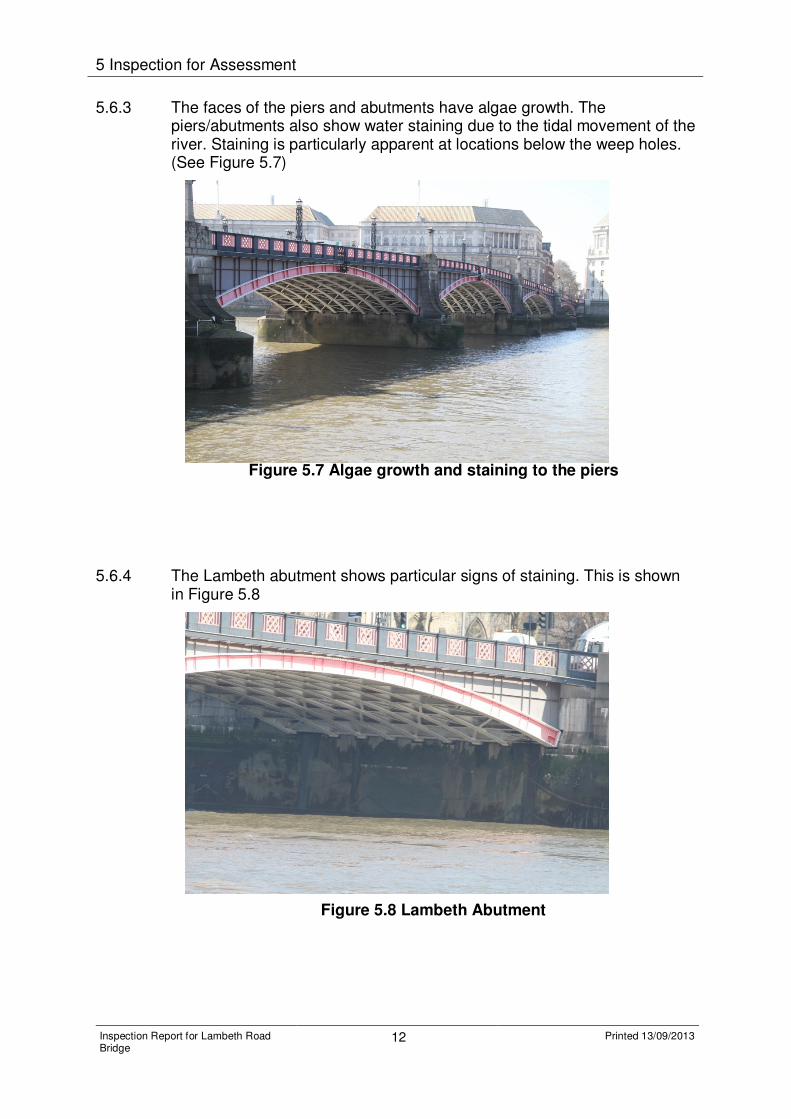
5.6.3 The faces of the piers and abutments have algae growth. The piers/abutments also show water staining due to the tidal movement of the river. Staining is particularly apparent at locations below the weep holes. (See Figure 5.7)

Figure 5.7 Algae growth and staining to the piers

5.6.4 The Lambeth abutment shows particular signs of staining. This is shown in Figure 5.8

Figure 5.8 Lambeth Abutment

5 Inspection for Assessment

Inspection Report for Lambeth Road Bridge

13 Printed 13/09/2013

5.7 Foundations

5.7.1 The foundations are buried; hence close inspection was not possible. There was no evidence of defects (settlement etc) that would suggest the foundations of the structures are in any distress.

6 Conclusions and Recommendations

Inspection Report for Lambeth Road Bridge

14 Printed 13/09/2013

6 Conclusions and Recommendations

6.1 General

6.1.1 There is no significant deterioration since the previous special inspection. None of the defects set out above needs to be allowed for in the assessment. The general maintenance issues noted during the inspection should be carried out as part of the general maintenance of the structure.

6.2 Condition Factor

A condition factor of 1.0 is recommended for all elements of this structure based on the information gathered during the inspection. However, based on the corrosion noted in the last principal inspection report and the potential impact this might have on the structure unless maintenance is carried out, a sensitivity analysis will be made during the assessment of the effects of reducing the condition factor on the bracing.

Appendices

Inspection Report for Lambeth Road Bridge

15 Printed 13/09/2013

Glossary

Term Description

PI Principal Inspection

GI General Inspection

Copyright notice Copyright © Thames Water Utilities Limited September 2013. All rights reserved. Any plans, drawings, designs and materials (materials) submitted by Thames Water Utilities Limited (Thames Water) as part of this application for Development Consent to the Planning Inspectorate are protected by copyright. You may only use this material (including making copies of it) in order to (a) inspect those plans, drawings, designs and materials at a more convenient time or place; or (b) to facilitate the exercise of a right to participate in the pre-examination or examination stages of the application which is available under the Planning Act 2008 and related regulations. Use for any other purpose is prohibited and further copies must not be made without the prior written consent of Thames Water. Thames Water Utilities LimitedClearwater Court, Vastern Road, Reading RG1 8DB The Thames Water logo and Thames Tideway Tunnel logo are © Thames Water Utilities Limited. All rights reserved.

Copyright notice Copyright © Thames Water Utilities Limited September 2013. All rights reserved. Any plans, drawings, designs and materials (materials) submitted by Thames Water Utilities Limited (Thames Water) as part of this application for Development Consent to the Planning Inspectorate are protected by copyright. You may only use this material (including making copies of it) in order to (a) inspect those plans, drawings, designs and materials at a more convenient time or place; or (b) to facilitate the exercise of a right to participate in the pre-examination or examination stages of the application which is available under the Planning Act 2008 and related regulations. Use for any other purpose is prohibited and further copies must not be made without the prior written consent of Thames Water. Thames Water Utilities LimitedClearwater Court, Vastern Road, Reading RG1 8DB The Thames Water logo and Thames Tideway Tunnel logo are © Thames Water Utilities Limited. All rights reserved.

10243-A4P-Copyright-imp-V01.pdf p1 12:03:39 September 21, 2013


Recommended