100
Application Server 6.0 User Guide
OL-28804-01
Application Server 6.0 User Guide


Please Read
Important Please read this entire guide. If this guide provides installation or operation instructions, give particular attention to all safety statements included in this guide.
Notices
Trademark Acknowledgments Cisco and the Cisco logo are trademarks or registered trademarks of Cisco and/or its affiliates in the U.S. and other countries. To view a list of Cisco trademarks, go to this URL: www.cisco.com/go/trademarks.
Third party trademarks mentioned are the property of their respective owners.
The use of the word partner does not imply a partnership relationship between Cisco and any other company. (1110R)
Publication Disclaimer Cisco Systems, Inc. assumes no responsibility for errors or omissions that may appear in this publication. We reserve the right to change this publication at any time without notice. This document is not to be construed as conferring by implication, estoppel, or otherwise any license or right under any copyright or patent, whether or not the use of any information in this document employs an invention claimed in any existing or later issued patent.
Copyright © 2014 Cisco and/or its affiliates. All rights reserved.
Information in this publication is subject to change without notice. No part of this publication may be reproduced or transmitted in any form, by photocopy, microfilm, xerography, or any other means, or incorporated into any information retrieval system, electronic or mechanical, for any purpose, without the express permission of Cisco Systems, Inc.

OL-28804-01 iii
Contents
About This Guide v
Chapter 1 Getting Started 7 Power On the Application Server Workstation ................................................................... 8 Start Application Server Processes ........................................................................................ 9
Chapter 2 Setting Up Language Support 11 Set Up Supported Languages ............................................................................................... 12 Configure Screen Language ................................................................................................. 13 One-For-All ............................................................................................................................. 16
Chapter 3 Setting Up Described Video Services 19 Enable DVS Support .............................................................................................................. 21 Configure DVS Support ........................................................................................................ 25
Chapter 4 Defining PPV Services and Events 29 Define PPV Services ............................................................................................................... 30 Understanding Windows and Barkers ............................................................................... 35 Define PPV Events ................................................................................................................. 40 Configure Purchase PIN ....................................................................................................... 44
Chapter 5 Setting Up the Interactive Program Guide 45 Before You Begin .................................................................................................................... 47 Set Up the IPG ........................................................................................................................ 50 Add IPG Data Manually ....................................................................................................... 57 Add Your Company's Logo to the Main IPG Screen ........................................................ 59 Configurations That Enhance Your Subscribers' Experience .......................................... 62 IPG Memory Usage Settings ................................................................................................. 63 Adjust How DHCTs Use IPG Memory ............................................................................... 67 Selecting the Number of Days of IPG Data to Produce .................................................... 71 Graying Out Unauthorized Channels in IPG .................................................................... 72
Chapter 6 Setting Up a Virtual Channel Service 73 Configure the VCS Broadcast File System (BFS) ............................................................... 74 Build a Virtual Channel Source File .................................................................................... 77
Contents
iv OL-28804-01
Set Up a Virtual Channel Service ......................................................................................... 80
Chapter 7 Enabling Power On Features 83 Set Up Power On Keys .......................................................................................................... 84 Configure Power On Keys .................................................................................................... 85 Upgrade From AS 3.5 or Earlier ........................................................................................... 88 Configure Power On Channel Options ............................................................................... 89
Chapter 8 Enabling Tracing on the Application Server 93 Enabling Logging ................................................................................................................... 94 View the Log Files .................................................................................................................. 95
Chapter 9 Customer Information 97

About This Guide
OL-28804-01 v
About This Guide
Introduction The Cisco Application Server works with the Explorer Controller (EC) to deliver digital applications to subscribers. Together, the Application Server and the EC form the core of the Digital Broadband Delivery System (DBDS). The DBDS delivers broadcast data and digital applications from the headend to the subscribers’ homes.
This guide provides procedures for setting up and managing digital applications such as pay-per-view (PPV) and the Interactive Program Guide (IPG) on the Application Server.
This guide contains procedures for defining digital applications as well as deleting and changing the definitions for these applications. You will not complete these procedures in the order they are presented here. In addition, you will not necessarily use all of the procedures in this guide, depending on the applications that you offer to your subscribers.
Note: The illustrations and screen captures shown in this guide may not exactly match what is displayed on your system.
Purpose The purpose of this guide is to enable users to manage the applications that reside on Application Server 6.0. You will learn how to set up, or provision, each of the applications that reside on the Application Server.
Prerequisites Application Server 6.0 (AS 6.0) requires System Release (SR) 6.0 and later.
Audience This guide is intended for system operators who are using Application Server 6.0 with the system release listed earlier.
Document Version This is the first formal release of this document.


OL-28804-01 7
This chapter provides procedures for starting up the Cisco Application Server workstation and its processes. Use the procedures in this chapter if you are starting up the Application Server for the first time or if power to the Application Server has been interrupted.
Typically, the Application Server operates continuously until you stop it manually to upgrade it. If you are upgrading the Application Server, do not use the procedures in this chapter to restart the Application Server after the upgrade. Instead, use the procedures provided in the appropriate upgrade installation instructions for your system release.
1 Chapter 1 Getting Started
In This Chapter ¡ Power On the Application Server Workstation .................................. 8 ¡ Start Application Server Processes ....................................................... 9

Chapter 1 Getting Started
8 OL-28804-01
Power On the Application Server Workstation Before you power on the Application Server workstation, the EC processes must be running and you must have your login password. If you do not know your login password, consult your system administrator.
Complete these steps to power on the Application Server workstation.
1 Go to the Application Server workstation and press the Power button. The login window opens with a welcome message after a few minutes.
Note: If your system is not set up properly, the Application Server will not finish powering up. If your Application Server does not power on, contact Cisco Services at 1-800-283-2636.
2 Type the user name (typically dncs), and then press Enter. The password prompt appears.
3 Type the password, and then press Enter. The Application Server desktop appears. The Application Server workstation is now powered up.
4 Your next step is to start the Application Server processes. Go to Start Application Server Processes (on page 9).

Start Application Server Processes
OL-28804-01 9
Start Application Server Processes After you power on the Application Server workstation, you can start the Application Server processes. These processes are an integral part of the Application Server software. You cannot use the Application Server with the EC until you start these processes.
Complete these steps to start the Application Server processes:
1 Use the mouse to place the cursor anywhere on the Application Server desktop, and then click the middle mouse button. A drop-down menu appears with a list of options.
2 Click App Serv Start. The workstation front-panel "busy" light blinks to indicate that the software startup is in process.
Monitoring Application Server Processes If you want to monitor each Application Server process as it starts, complete these steps:
1 When you log in to the EC status window, the initial screen shows all EC and Application Server processes and their working states, similar to the following example. A green state indicates that a process is running. A red state indicates that a process is not running.
2 Wait until all processes show a status of running (green).
3 Leave this window open and visible to help you monitor the system.

Chapter 1 Getting Started
10 OL-28804-01
What's Next? After you have verified that all of the processes are running properly, your next step is to set up the applications that you offer to your subscribers. Most of the following chapters contain procedures for defining the applications you offer subscribers and changing the way the applications are configured.
Enabling Tracing on the Application Server (on page 93) contains procedures to enable and disable the tracing function and to specify the level of detail that you want to include in the log file.

OL-28804-01 11
This chapter explains how to configure the EC to display the Interactive Program Guide (IPG) and PPV/IPPV event information menus in one of several languages.
Important: Configuring the EC for language support requires the following support from other vendors:
¾ To provide IPG in a different language, your data provider must provide programming information, such as titles in those languages.
¾ To provide PPV/IPPV titles in a different language, the billing system must provide this information as a part of the event definition.
2 Chapter 2 Setting Up Language Support
In This Chapter ¡ Set Up Supported Languages .............................................................. 12 ¡ Configure Screen Language ................................................................ 13 ¡ One-For-All ............................................................................................ 16

Chapter 2 Setting Up Language Support
12 OL-28804-01
Set Up Supported Languages To set up other languages for your IPG, choose Server Applications > Languages in the main window. For each language that you set up, there must be an IPG server and an IPG collector to support the language. The EC allows one IPG server per active language. You must complete the following tasks when setting up supported languages.
1 Verify and select the appropriate languages your system supports.
2 Create a server and a collector for each language you select.
For procedures to create a server and a collector, see Setting Up the Interactive Program Guide (on page 45).
Verifying and Selecting the Appropriate Languages Perform the following steps to verify that the EC recognizes the languages that your DBDS supports.
1 In the main window, choose Server Applications > Languages. The Supported Languages window opens.
Note: Standard DHCT code supports English, French, and Spanish. Special DHCT code is required to support Japanese.
2 Be sure that the languages that your DBDS supports are selected.
Note: In the example in Step 2, only English is selected. However, if your system supports other languages, select those options as well, and then click Save.

Configure Screen Language
OL-28804-01 13
Configure Screen Language The language set on the Application Server is shown on the screen and is called the "screen language." Screen Language can be configured as either a global or an addressable feature.
On the General Settings tab in the Global Configuration window, you can use Language: Screen to determine whether the Screen Language feature should be an Addressable option (meaning that the subscriber can change it from the set-top menu) or a Global option (meaning that you will set it in the headend for all subscribers).
When checked, the Language: Screen check box enables Addressable configuration. When unchecked, the Language: Screen check box enables Global configuration.
Global Configuration provides procedures to enable and disable the tracing function and to specify the level of detail that you want to include in the log file. The Global configuration affects all the set-tops in the network.
¾ Screen Language is set from the Application Server.
¾ Screen Language is not displayed in General Settings on the set-top box.

Chapter 2 Setting Up Language Support
14 OL-28804-01
If Screen Language is a Global Configuration, the Screen Language drop-down list appears on the Base Application tab of the Global configuration window, but it does not appear on the Base Application tab of the Addressable or Staging configuration windows.
Changing from Addressable to Global Configuration You can change Screen Language from an Addressable configuration to a Global configuration.
1 In the Set Up Global DHCT Configuration area on the General Settings tab, ensure the Screen Language feature is unchecked. This enables the Global configuration.
2 The Screen Language option is no longer displayed in the General Settings on each set-top box.
Note: Until the Global configuration is reconfigured from the server, the Addressable configuration value will be used. After the server is reconfigured and the Global configuration is set, it will override any Addressable configurations.
Addressable Configuration The Addressable configuration affects individual set-tops. Screen Language can be set from the set-top General Setting Menu.
Note: If the Global configuration is set, it will override any Addressable configurations.

Configure Screen Language
OL-28804-01 15
If Screen Language is an Addressable and Staging Configuration, the Screen Language combo list appears in the Base Application of Addressable and Staging Configuration and does not appear in the Base application of Global configuration.
Changing from Global to Addressable Configuration If Screen Language is configured as Global, it can later be changed to an Addressable configuration.
1 On the Global/General Settings tab, ensure that the Screen Language feature is checked. This enables the Addressable configuration.
2 The Screen Language option is now displayed in the General Settings menu on each set-top box.
Note: The original, Global configuration value will be used until the Screen Language option in General Settings is reconfigured from each set-top box.

Chapter 2 Setting Up Language Support
16 OL-28804-01
One-For-All One-For-All is a feature that checks to see if PPV event descriptions are available in more than one language in an attempt to avoid showing the text "No description available."
Background The IPG lists PPV events by title. Subscribers also want to see a PPV event summary called a description but unfortunately, service providers do not supply descriptions in all languages. When a description is not available in the IPG language, subscribers see the text "No description available."
PPV Event Descriptions Without One-For-All Without One-For-All, the Application Server populates the IPG with PPV event descriptions available in the screen language.
Note: The language set on the Application Server is called the screen language. For more details, see Configure Screen Language (on page 13).
The following table shows that if the screen language is English and the PPV event description is English, then subscribers will see the English description. If the screen language is English and the PPV event description is not English, then subscribers will see the text "No description available."
Screen Language Set on the Application Server
Event Description Available in Screen Language?
This Description is Populated in an IPG without One-For-All
English Yes Description in English
French Yes Description in French
English No No description available in English
French No No description available in French
PPV Event Descriptions With One-For-All One-For-All is a strategy to show PPV event descriptions, even if the description is not offered in the screen language. To enable One-For-All, the operator sets a default language in the .profile file. For directions, see Configuring One-For-All (on page 17).
Note: The language set in the .profile file is the default language. Since this is an alternate language to check for a description, the operator must set a language in the .profile file that is different from the screen language and which may have a description available.

One-For-All
OL-28804-01 17
Every time a description is not available in the screen language, One-For-All triggers the Application Server to look for a description in the default language. If a description is available in the default language, then the Application Server will populate the IPG with a PPV event description in the default language.
For instance, the following table shows that sometimes the PPV event description is not available in the screen language but the PPV event description is available in the default language. If, for example, English is the screen language and French is the default language, and the PPV event description is not available in English but is available in French, then subscribers will see the PPV event description in French.
Finally, if the PPV event description is not available in either the screen language or the default language, then subscribers will see the text "No description available."
Screen Language Set on the App Server
Description Available in Screen Language?
Default Language Set in the .profile
Description Available in Default Language?
This Description is Populated in an IPG with One-for-All
English No French Yes Description in French
French No English Yes Description in English
English No French No No description available in English
French No English No No description available in French
Note: French and English have been used in these tables as arbitrary examples. IPG data is available in English, French, Spanish, and in Japanese for SR 4.0, 4.2 and later, and in Arabic for SR 4.3 and later.
Configuring One-For-All Complete these steps to configure One-For-All:
1 Open an xterm window on the EC.
2 Type cd /export/home/dncs and press Enter. The /export/home/dncs directory is now the working directory.
3 Type vi .profile and press Enter. The vi editor opens the .profile file for editing.
Note: Be sure to type a period (.) before the word "profile."
4 Use the arrow keys to move to the bottom of the file.
5 Type o. A new line appears at the end of the file.
6 Type the following lines at the end of the file and press Enter after each line.
PPV_DEFAULT_LANGCODE="<language>";
export PPV_DEFAULT_LANGCODE;
Examples (English, French, Spanish, Japanese and Arabic):

Chapter 2 Setting Up Language Support
18 OL-28804-01
PPV_DEFAULT_LANGCODE="eng";
PPV_DEFAULT_LANGCODE="fra";
PPV_DEFAULT_LANGCODE="spa";
PPV_DEFAULT_LANGCODE="jpn";
PPV_DEFAULT_LANGCODE="ara";
Important: Ensure that the PPV_DEFAULT_LANGCODE that you set (the "default language") is different from the Application Server language (the "screen language"), and is likely to be used for a PPV event description. For more about the screen language, see Configure Screen Language (on page 13).
Notes:
¡ Currently, five language options are available. To set the default language to English, type "eng". For French, type "fra". For Spanish, type "spa".
¡ Japanese "jpn" is available for SR 4.0, 4.2 and later.
¡ Arabic "ara" is available for SR 4.3 and later.
7 Press Esc.
8 Type :wq and press Enter. The vi editor saves and closes the .profile file.
9 On the Application Server, you must stop and restart the PPV processes to activate these new values. See Stopping and Restarting a Server Process (on page 52) for more information.
OL-28804-01 19
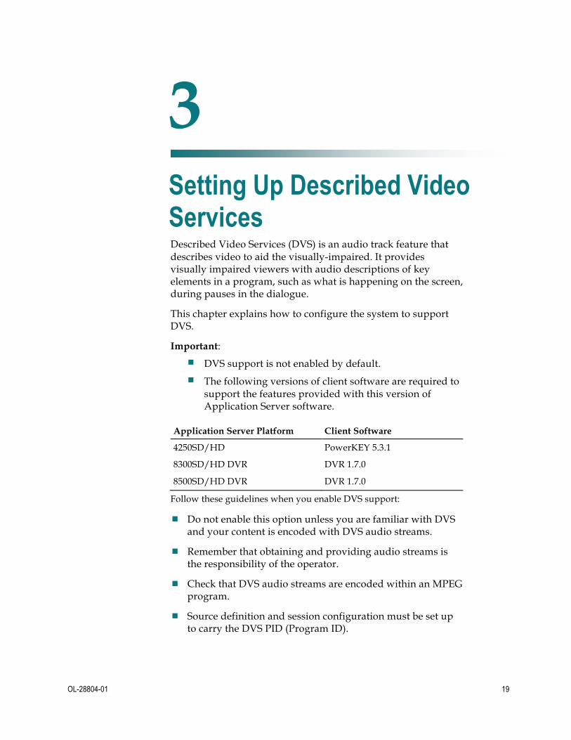
Described Video Services (DVS) is an audio track feature that describes video to aid the visually-impaired. It provides visually impaired viewers with audio descriptions of key elements in a program, such as what is happening on the screen, during pauses in the dialogue.
This chapter explains how to configure the system to support DVS.
Important:
¡ DVS support is not enabled by default.
¡ The following versions of client software are required to support the features provided with this version of Application Server software.
Application Server Platform Client Software
4250SD/HD PowerKEY 5.3.1
8300SD/HD DVR DVR 1.7.0
8500SD/HD DVR DVR 1.7.0
Follow these guidelines when you enable DVS support:
¾ Do not enable this option unless you are familiar with DVS and your content is encoded with DVS audio streams.
¾ Remember that obtaining and providing audio streams is the responsibility of the operator.
¾ Check that DVS audio streams are encoded within an MPEG program.
¾ Source definition and session configuration must be set up to carry the DVS PID (Program ID).
3 Chapter 3 Setting Up Described Video Services

Chapter 3 Setting Up Described Video Services
20 OL-28804-01
In This Chapter ¡ Enable DVS Support ............................................................................. 21 ¡ Configure DVS Support ....................................................................... 25
Enable DVS Support
OL-28804-01 21
Enable DVS Support
Overview Setting up DVS support is a two-step process:
1 Enable DVS support on the system
¡ Global configuration: Enable DVS support on the system
¡ Hub configuration: Enable or disable DVS support for specific hubs on the system
2 Configure DVS support on the set-top
¡ Staging defaults configuration: Configure DVS support during the staging process, so that all set-tops receive the same configuration when they are staged
¡ Addressable configuration: Configure DVS support on a single set-top, identified by MAC address
¡ Subscriber configuration: The subscriber can configure and enable or disable DVS support
For more information about configuring EC settings, see Enhancing Your Subscribers' Experience: SARA Configurable Options (part number 78-4002178-01).
Enabling Global DVS Support The parameters that you set in the Set Up Global DHCT Configuration window affect the parameters that are available in the Addressable, Hub, and Staging Defaults windows.
When DVS support is globally enabled, the Audio: Described option is visible on the Addressable/Staging and on hub configurations. When DVS support is disabled, set-tops do not show the Audio: Described option in General Settings on the UI.
Important:
¡ Once DVS support has been enabled globally, support must be configured on the set-tops before subscribers can use DVS.
¡ Global settings for DVS support override individual set-top settings.
Follow these steps to enable DVS support on all of the set-tops in your network.
1 In the main window, choose Server Applications > DHCT Config. The DHCT Configure window opens:
2 Click Global. The Set Up Global DHCT Configuration window opens.
3 Click the General Settings tab.

Chapter 3 Setting Up Described Video Services
22 OL-28804-01
4 Be sure that the DVS Support check box in the User Menu Options area is checked, as shown in the following example:
5 Click Save to save your changes, then click Cancel to close the window. Support
for DVS has now been successfully activated on your EC.
Enabling and Disabling DVS Support on a Hub DVS can be selectively enabled or disabled on hubs. DVS support settings at the hub level will override the global configuration.
Important: DVS support must be enabled globally before the hub can be configured. If you have not enabled DVS support on the system, return to Enabling Global DVS Support (on page 21) before you attempt the following steps.
When setting Hub-level control of DVS support, you will first enable DVS support in the UI. Then you can choose to enable or disable DVS support on the hub.
Enable the DVS Support in the User Interface 1 From the main window, choose Server Applications > DHCT Config. When the
DHCT Configure window opens, choose Hub.
2 Click Select Hub-Specific Items.
3 Click New Hub-Specific.
4 In the Select Hub-Specific Items window, click the General Settings tab.
Enable DVS Support
OL-28804-01 23
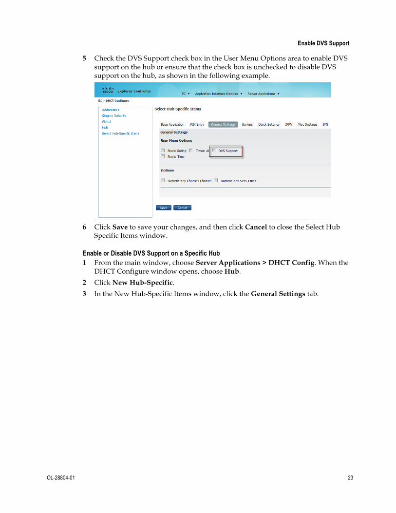
5 Check the DVS Support check box in the User Menu Options area to enable DVS support on the hub or ensure that the check box is unchecked to disable DVS support on the hub, as shown in the following example.
6 Click Save to save your changes, and then click Cancel to close the Select Hub
Specific Items window.
Enable or Disable DVS Support on a Specific Hub 1 From the main window, choose Server Applications > DHCT Config. When the
DHCT Configure window opens, choose Hub.
2 Click New Hub-Specific.
3 In the New Hub-Specific Items window, click the General Settings tab.

Chapter 3 Setting Up Described Video Services
24 OL-28804-01
4 Check the DVS Support check box in the User Menu Options area to enable DVS support on the hub or ensure that the check box is unchecked to disable DVS support on the hub, as shown in the following example.
5 Click Save. The Application Server sends the configuration to all the set-tops in
the hub that you specified. Changes should be available on each set-top in a few minutes.
Note: After you send a hub-specific configuration, any changes that you make to the global configuration do not affect the hub-specific settings. From now on, if you need to change an option that affects all of the set-tops in your network, you will need to make this change in the global configuration and in the hub-specific configurations for any hubs that require this change.
6 Click Cancel to close the Select New Hub Specific window. Support for DVS has now been successfully enabled or disabled on the hub.

Configure DVS Support
OL-28804-01 25
Configure DVS Support After you enable DVS support on the system, you must configure the set-tops.
Configuring DVS Support During Staging Set-tops (unless specifically configured) are configured for DVS support during staging.
Note: The staging value for DVS support (enabled or disabled) is used by the set-top when it first connects to the network or when nvm clear is performed on the set-top.
Follow these steps to configure DVS support on set-tops during the staging process.
1 In the main window, choose Server Applications > DHCT Config. The DHCT Configure window opens.
2 Click Staging Defaults.
3 In the Set Up Staging Defaults window, click the Base Application tab.
4 Check the Audio: Described check box in the Options area.
5 Click Save to save your changes, then click Cancel to close the window. DVS
support has now been successfully configured on your set-tops.
Chapter 3 Setting Up Described Video Services
26 OL-28804-01
Configuring DVS Support on a Single Set-Top Set-tops can be configured individually for DVS support from the network headend. Once staged, a specific set-top identified by a MAC address can be enabled or disabled.
Important: Addressable configuration information is not stored on the Application Server. The set-top must be plugged in and functional to receive the addressable configuration message.
Follow these steps to configure DVS support on a single, addressable set-top.
1 In the main window, choose Server Applications > DHCT Config. When the DHCT Configure window opens, choose Addressable.
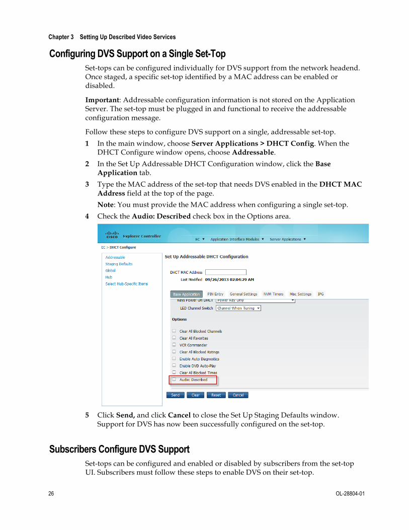
2 In the Set Up Addressable DHCT Configuration window, click the Base Application tab.
3 Type the MAC address of the set-top that needs DVS enabled in the DHCT MAC Address field at the top of the page.
Note: You must provide the MAC address when configuring a single set-top.
4 Check the Audio: Described check box in the Options area.
5 Click Send, and click Cancel to close the Set Up Staging Defaults window.
Support for DVS has now been successfully configured on the set-top.
Subscribers Configure DVS Support Set-tops can be configured and enabled or disabled by subscribers from the set-top UI. Subscribers must follow these steps to enable DVS on their set-top.

Configure DVS Support
OL-28804-01 27
1 Choose General Settings > Audio: Described.
2 Use the arrows on the remote control to choose Enabled.
Subscribers Quick Settings DVS Experience When DVS support has been activated, subscribers will notice a change in the Choose Language option in their Quick Settings menu. Available languages will be identified with a "DVS" precursor (such as DVS:English in the following example).
For more information about the user interface, see Set Up the IPG (on page 50).


OL-28804-01 29
This chapter explains how to define PPV services and events. It also describes the purpose of windows and barkers.
4 Chapter 4 Defining PPV Services and Events
In This Chapter ¡ Define PPV Services .............................................................................. 30 ¡ Understanding Windows and Barkers .............................................. 35 ¡ Define PPV Events ................................................................................ 40 ¡ Configure Purchase PIN ...................................................................... 44
Chapter 4 Defining PPV Services and Events
30 OL-28804-01
Define PPV Services This section explains how to create, modify, and delete PPV services.
Before You Begin Before you can define PPV events for subscribers to purchase, you must define the PPV services that will deliver these events. A PPV service is an application that allows subscribers to purchase movies, concerts, or sporting events and view them at a certain time on a certain channel. A PPV event is any program (such as movie, concert, or sporting event) that a subscriber can purchase through a PPV service. If a subscriber has purchased the event that is currently playing on the PPV service, then the PPV service displays that event. If not, then the PPV service displays advertising, interstitials, or some other programming.
As with other services, you must complete the following tasks when defining a PPV service:
¾ Add the service source to the EC. This task specifies which digital or analog signal the DBDS will use to deliver the service to subscribers.
¾ Define parameters for the service source. This task defines the attributes that establish how the system will process service content. Also, this task includes building a session, which defines and allocates the resources that the source will use to deliver the service content.
¾ Encrypt the content coming from the service source. This task ensures that the content will only be available to authorized subscribers.
Before you can define PPV services, the service on which a PPV service is built must be registered with the Service Application Manager (SAM), Event Use Service, Subscription Service (if used), and Interstitial Service. These are described in more detail later in this section. The SAM is a table that identifies available services and their associated applications. The EC automatically registers the service with the SAM when you create the service, so that you do not need to register an event's service with the SAM.

Define PPV Services
OL-28804-01 31
Understanding the Add PPV Service Window Use the Add PPV Service window to set up PPV services.
The fields in this window are as follows:
¾ Service Name: A unique name for the service, typically provided by the billing system.
¾ Short Description: A useful descriptive short name, such as IPPV1 and IPPV2 for subscribers when they tune to the channel where this PPV service resides.
¾ Long Description: A longer description that provides a more complete definition of the service. This is for your benefit only. Subscribers never see the information entered here.
¾ Logo Index (Optional): A number that associates a graphic with the PPV service. You can obtain a list of logo numbers from your account representative.
¾ Default Order Phone Number: Specifies the phone number for subscribers to call to order a reservation pay-per-view (RPPV) event advertised by this service. The number you enter displays for subscribers unless the billing system provides another telephone number. Type this phone number exactly as it should appear on the TV screen (including dashes and parenthesis, if appropriate).
¾ Default Cost (Optional): Sets the default cost for events on the service if no cost is specified for the event. Type this amount exactly as it should appear on the TV screen (including a dollar sign and decimal point, if appropriate).
¾ Default Order Start Interval (Optional): Specifies a default interval during which subscribers can call to order an event, if the event definition does not specify when subscribers can order the event. For example, suppose the Default Order Start Interval is 12 hours and 0 minutes. If an event does not specify an order start time, then subscribers can begin calling to order the event 12 hours before the event begins. Type this amount in hours and minutes.

Chapter 4 Defining PPV Services and Events
32 OL-28804-01
¾ Event Use Service: The service that will be seen on this PPV service when PPV events are purchased. Click the arrow to display a list of all services available, and then choose the appropriate service from the drop-down list.
¾ Subscription Service (Optional): Specifies whether this service will function as a subscription service in addition to a PPV service.
- If you want the service to function as a PPV service, choose none.
- If you want the service to function as a subscription service (one that is always available to authorized subscribers), choose the same service that you selected from the Event Use Service drop-down list.
¾ Interstitial Service (Optional): A specific service that is displayed between events; this service could be general programming or an advertisement. Choose from the list of existing services. If you do not specify an interstitial service, the PPV service channel will display a standard text barker between events.
Creating a PPV Service After you have built the services, the next step is to create a service that advertises and sells the events: a PPV service.
Complete these steps to create a PPV service:
1 In the main window, choose Server Applications > PPV Service.
2 Click Add. The Add PPV Service window opens, similar to the following example.
3 In the Add PPV Service window, complete all of the following required fields.
Optional fields are labeled. See Understanding the Add PPV Service Window (on page 31) for descriptions of these fields.
Note: Be sure to make a note of the values in the Short Description field and the Event Use Service field. You will need these values when you set up this PPV service on the IPG.
¡ Service Name

Define PPV Services
OL-28804-01 33
¡ Short Description
¡ Long Description
¡ Logo Index (Optional)
¡ Default Order Telephone Number
¡ Default Cost (Optional)
¡ Default Order Start Interval (Optional)
¡ Event Use Service
¡ Subscription Service (Optional)
¡ Interstitial Service (Optional)
4 Click Save. The Application Server creates a PPV service for the source and automatically does the following:
¡ Registers the service with the SAM
¡ Assigns a URL of ippv to the service
¡ Makes the service available to the channel maps
¡ Creates an unlimited segment from the service, which you can view in the Segment List
Note: For each PPV service, there are two SAM services: the PPV service and the Event Use service. You must map both the PPV service and the Event Use service to the IPG Service List to ensure that data about the events appears in the IPG and on the purchase barkers.
5 Do you want to add another PPV service?
¡ If yes, go back to Step 3 and add the next service.
¡ If no, go to Step 7.
6 Add all of the PPV services that you created and all of their Event Use services to the IPG Service List. For assistance, go to Set Up the IPG (on page 50) and follow the instructions.
7 Add all of the PPV services that you created to the channel map. Refer to your online help for procedures to complete this task.
8 Does your system support Explorer 3100HD DHCTs?
¡ If yes, ensure that the SAM URL of any PPV service that contains high-definition (HD) content includes the HD flag. If this flag is absent in HD content, 3100HD DHCTs cannot display PPV barkers and other graphics over HD content. As a result, full-screen HD content is displayed over PPV preview graphics and enables subscribers to receive the entire HD event for free. For assistance adding the HD flag to the SAM URL of HD PPV services, see Enhancing Your Subscribers' Experience: SARA Configurable Options (part number 78-4002178-01).

Chapter 4 Defining PPV Services and Events
34 OL-28804-01
Note: The HD flag (;HD) must be attached to the end of the SAM Service URL (inthe Add SAM Service window) as shown in this example: bfs://resapp/watchtv;HD.
¡ If no, you have completed defining PPV services. For a better understanding of how PPV events are offered to subscribers, see Understand Windows and Barkers (see "Understanding Windows and Barkers" on page 35).
Modifying a PPV Service Complete these steps to modify a PPV service:
1 In the PPV Service List window, select the service that you want to edit.
2 Click Edit. The Edit PPV Service window opens, similar to the following example.
3 Make necessary changes in the fields, and click Save.
Deleting a PPV Service Complete these steps to delete a PPV service:
Important: The system will not allow you to delete a service if events also use the service.
1 Select the service that you want to delete in the PPV Service list window, and choose Delete. A dialog box prompts you to confirm that you want to delete the current item.
2 Click Yes to confirm that you want to delete the PPV service.

Understanding Windows and Barkers
OL-28804-01 35
Understanding Windows and Barkers PPV events are available for viewing during a specified period of time. This period of time is called a window. The period of time that a window is present determines when the PPV service displays a specific type of advertisement or purchase option. These advertisements and purchase options are presented by screens called barkers.
This section describes the types of windows and barkers used in offering PPV events to subscribers. You must understand the relationship between windows and barkers in order to define PPV events successfully.
Note: Remember, a window is a period of time. A barker is a screen that advertises an event or allows a subscriber to order an event.
Windows PPV services use six different types of windows to offer events to subscribers. Some windows are used for both RPPV and impulse pay-per-view (IPPV) events, and some are used for IPPV events only. The following table describes the different windows and the associated PPV event.
Type of Window
Purpose
Event Window This window defines the period of time that video is shown on the PPV service channel. The event's start time and length determine this time period.
Marketing Window
This window defines the period of time that the PPV service can advertise the event. During the Marketing window, a Purchase Prompt barker appears when the subscriber sets a reminder or VCR timer for the event. This also allows subscribers to purchase an IPPV event from the IPG.
Important: The Marketing Window should be at least as long as the number of days of IPG data you provide (typically seven days).
Advertising Window
This window defines the period of time that the Purchase barker appears when the subscriber is tuned to the PPV service channel. Each PPV service may have only one Advertising window open at a time.
Preview Window
This window defines the period of time that a subscriber may view the IPPV event on the PPV service channel without purchasing the event. During this time, if the subscriber has not purchased the event, the Preview barker appears. When a subscriber purchases the event, the event appears.
Buy (GBAM) Window
This window defines the period of time that the PPV service will attempt to verify IPPV event purchases. If the PPV service verifies the purchase, the subscriber will see the event. (The Buy window uses a Global Broadcast Authenticated Message [GBAM] to verify a purchase.)

Chapter 4 Defining PPV Services and Events
36 OL-28804-01
Type of Window
Purpose
Cancel Window This window defines the period of time that a subscriber may cancel an IPPV event purchase.
Window Relationships There are some timing requirements that you must follow when setting up PPV windows. If you do not follow these requirements, then subscribers may not be able to purchase PPV events successfully. For example, if you do not define an Advertising window correctly, then the Purchase barker will not appear when subscribers tune to the PPV service channel. In this case, subscribers are unable to purchase the event. Or, if you do not define the event itself correctly, then the event will not appear as expected.
In examining the window relationships in the following illustration, remember that the billing system defines these windows when it sends the event definition to the Application Server. Therefore, in most cases you should not need to define an event (although you can do so manually if necessary.) You can view the Set Up PPV Event window to view the window definitions for an event.

Understanding Windows and Barkers
OL-28804-01 37
Note: For IPPV events, you must define the Marketing, Advertising, Buy (GBAM), and Event windows. For RPPV events, you only need to define three windows: the Marketing, Advertising, and Event windows.
Barkers A barker is often associated with a specific window. PPV uses three kinds of barkers. These barker types are as follows:
¾ Purchase Prompt barker: This barker prompts subscribers to buy an event when the subscriber performs one of the following actions:
- Sets the VCR timer to record an event that has not yet occurred
- Uses a reminder timer to notify the subscriber of an event to view in the future
Subscribers can dismiss this barker by pressing the C key on the remote control. This barker appears during the Marketing window.
¾ Purchase barker: This barker advertises the next event available for purchase. This barker appears until the subscriber buys the event, selects a different channel, or views the Advertising window.
¾ Preview barker: This barker is similar to the Purchase barker. In addition to

Chapter 4 Defining PPV Services and Events
38 OL-28804-01
displaying information about the event, the Preview barker also displays a portion of the event as part of the advertisement.
Note: The Purchase Prompt barker and the Purchase barker appear for both RPPV and IPPV events. The Preview barker appears only for IPPV events.
PPV Advertising Window Defaults By default, the advertising window starts 15 minutes before an event starts and ends 45 minutes after an event starts. These values are called the start offset and the end offset. We suggest that you adjust these values if you frequently have events that are less than 60 minutes long.
Before you adjust these offsets, you must identify the length of the shortest event that you will advertise. The length of your shortest event is your minimum event interval. Use the minimum event interval and the following guidelines to determine the new default values for your offsets:
¾ The total offset time (start offset plus end offset) must not exceed your minimum event interval. For example, if your shortest event is 30 minutes long, then the start offset plus the end offset must not exceed 30 minutes.
¾ For IPPV events, the purchase window cannot start before the advertising window starts.
¾ The advertising window must end at least 5 minutes before the end of the event.
The following table shows two examples of minimum event intervals and identifies acceptable default values for the start offset and the end offset.
Minimum Event Interval
Advertising Window Start Offset
Advertising Window End Offset
30 minutes 10 minutes 15 minutes
59 minutes 15 minutes 35 minutes
Modifying Default Values for PPV Advertising Windows After you determine the default offset values for the Advertising Window, follow these steps to adjust those values:
1 Open an xterm window on the EC.
2 Type cd /export/home/dncs and press Enter. The /export/home/dncs directory is now the working directory.
3 Type vi .profile and press Enter. The vi editor opens the .profile file for editing.
Note: Be sure to type a period (.) before the word "profile."
4 Use the arrow keys to move to the bottom of the file.
5 Type o. A new line appears at the end of the file.
6 Type the following lines at the end of the file and press Enter after each line.
Understanding Windows and Barkers
OL-28804-01 39
export PPV_ADV_WIND_START_INTVL=[number of seconds for new default start offset]
export PPV_ADV_WIND_END_INTVL=[number of seconds for new default end offset]
Examples: PPV_ADV_WIND_START_INTVL=600 PPV_ADV_WIND_END_INTVL=900
7 Press Esc.
8 Type :wq and press Enter.The vi editor saves and closes the .profile file.
9 On the Application Server, you must stop and restart the PPV processes to activate these new values. See Stopping and Restarting a Server Process (on page 52) for more information.

Chapter 4 Defining PPV Services and Events
40 OL-28804-01
Define PPV Events This section describes how to define the following types of events as defined by the billing system:
¾ RPPV event: Subscribers can purchase an RPPV event by placing a telephone call. A cable service representative (or an automated service) may order the event for the subscriber.
¾ IPPV event: Subscribers can purchase an IPPV event by using the remote control keys to purchase the event.
Note: After you define an event, you should use a DHCT in the headend to confirm that the event is available for ordering. By doing so, you can verify that the PPV service and the PPV event were defined correctly.
Generating PPV Events Automatically Typically, the billing system defines PPV events automatically. However, a solid understanding of how the billing system defines PPV events makes it easier for you to correct any errors that may occur.
Whether the billing system defines an event automatically, or you define one manually using the Application Server, either action generates an ECM (Entitlement Control Message). An ECM associates a package with the event and assigns an EID (Event ID) to the package. (Packages collect program segments into offerings that are meaningful to the subscriber and hold potential profitability for the MSO.)
Note: If you are generating IPPV events for a test lab, you can use the genPpvFromIpg utility to create PPV events using existing IPG data. The utility works by reformatting existing IPG data in the database into PPV data. For details, see Application Server Utilities (part number 78-749639-01).
Important: This utility is designed for use in test labs only. Do not run this utility on a live system.
The billing system automatically generates PPV events as follows:
1 The billing system sends the event definition to the Application Server.
2 The Application Server processes the definition and sends it to the EC for packaging.
3 Using the definition, the EC issues an ECM for the event. As part of issuing the ECM, the EC creates a package for the event and assigns the package an EID.
4 The EC transmits the ECM to a router, and the router forwards the ECM to the appropriate program QAM modulator.

Define PPV Events
OL-28804-01 41
Generating PPV Events Manually Even though your billing system typically generates PPV events automatically, you may occasionally need to set up an IPPV or RPPV event manually.
You can set up an event as either RPPV or IPPV, or you can set up a dual RPPV/IPPV event. When you set up a dual event, DHCTs that can purchase IPPV events will display IPPV advertisements for the event, and subscribers can purchase the event from the remote control. DHCTs will also display a telephone number for subscribers to call to order the event.
Note: If you are generating IPPV events for a test lab, you can use the genPpvFromIpg utility to create PPV events using existing IPG data. The utility reformats existing IPG data from the database into PPV data. For details, see Application Server Utilities (part number 78-749639-01). However, this utility is designed for use in test labs only. Do not run this utility on a live system.
Perform the following steps to create an IPPV event:
1 In the main window, choose Server Applications > PPV Event. The PPV Event List window opens.
2 Click Add to create a new event. The Add PPV Event window opens.
3 Click the Package Info tab.
4 In the top section of the tab, type the following information into their respective fields:
¡ Package Name: A name for the package
Chapter 4 Defining PPV Services and Events
42 OL-28804-01
¡ Start Date: The date when the package starts in MM/DD/YY format
¡ Start Time: The time when the package starts in HH:MM:SS format. Choose AM or PM
¡ Length: The length of the package in days, hours, and minutes
5 If you are setting up an RPPV event, choose Reservation Pay Per View.
6 If you want subscribers to be able to copy the event, choose Right To Copy Allowed. This option is only available for RPPV events.
7 If you are setting up an IPPV event, choose Impulse Pay Per View.
8 For IPPV events, complete the fields on the Preview, Buy Window, and Purchase Mode tabs to define how the window should function. See Understanding Windows and Barkers (on page 35) for information on how windows relate to each other. Otherwise, the Application Server applies the defaults to the data in these fields when you save it.
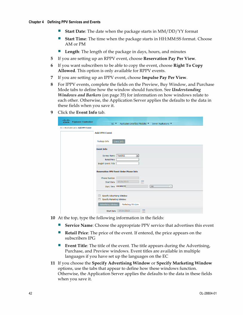
9 Click the Event Info tab.
10 At the top, type the following information in the fields:
¡ Service Name: Choose the appropriate PPV service that advertises this event
¡ Retail Price: The price of the event. If entered, the price appears on the subscribers IPG
¡ Event Title: The title of the event. The title appears during the Advertising, Purchase, and Preview windows. Event titles are available in multiple languages if you have set up the languages on the EC
11 If you choose the Specify Advertising Window or Specify Marketing Window options, use the tabs that appear to define how these windows function. Otherwise, the Application Server applies the defaults to the data in these fields when you save it.

Define PPV Events
OL-28804-01 43
12 Click Save when you finish entering all the data.
13 Check the PPV Service List to ensure that the source you created is on the list, and to verify that the source information is correct.
Note: The Application Server saves your changes.
Modifying a PPV Event Perform the following steps to modify a PPV service:
1 In the PPV Event List window, choose the event that you want to modify.
2 Click Edit. The Set Up PPV Event window opens with completed fields.
3 Make the necessary changes in the fields, and then click Save.
Deleting a PPV Event Perform the following steps to delete a PPV event.
1 Choose the event you want to delete in the PPV Event list window, and choose Delete. A Question window opens, prompting you to confirm that you want to delete the current item.
2 Click Yes to confirm.

Chapter 4 Defining PPV Services and Events
44 OL-28804-01
Configure Purchase PIN The Purchase PIN feature on the set-top is set to enabled by default; for this reason, the Purchase PIN screen is displayed by default. Some customers prefer that an operator be able to enable or disable this feature from the headend, so these new procedures facilitate remote access and control of the Purchase PIN.
You can enable or disable the set-top resident Purchase PIN feature globally from the Set Up Global DHCT Configuration screen.
1 In the main window, choose Server Applications > DHCT Config.
2 Click Global.
3 Click the PIN Entry tab.
4 Check the Enable Enhance Purchase PIN check box to enable the Purchase PIN feature, or uncheck it to disable the feature.

OL-28804-01 45
The IPG is an application that DHCTs use to display program information, such as the program name, start and end times, description, and rating. When you set up the IPG, the EC populates the IPG with data such as program listings and program descriptions. The Application Server provides other information on the IPG such as instructional text (for example, the words Browse By and Choose Date) and other General Settings menus. If you do not set up the IPG correctly, the IPG appears with no program information, even when a subscriber selects the Guide button.
IPG data is linked to a specific program service using the IPG service provider’s designation and the SAM service ID number. This link ensures that information and program descriptions are matched to the correct services.
This chapter provides procedures for setting up the IPG.
Important: Enabling DVS support on the Application Server allows you to offer your subscribers audio streams designed for the visually impaired. Once enabled, DVS will cause new IPG options to be displayed in Quick Settings and General Settings. For details about enabling DVS, see Enable DVS Support (on page 21).
Notes:
¾ Obtaining and providing audio streams is the responsibility of the operator.
¾ Audio streams must be encoded within an MPEG program.
¾ We recommend that this option not be enabled unless you are familiar with DVS and your content is encoded with DVS audio streams.
5 Chapter 5 Setting Up the Interactive Program Guide

Chapter 5 Setting Up the Interactive Program Guide
46 OL-28804-01
In This Chapter ¡ Before You Begin ................................................................................... 47 ¡ Set Up the IPG ....................................................................................... 50 ¡ Add IPG Data Manually ...................................................................... 57 ¡ Add Your Company's Logo to the Main IPG Screen ....................... 59 ¡ Configurations That Enhance Your Subscribers' Experience ......... 62 ¡ IPG Memory Usage Settings ............................................................... 63 ¡ Adjust How DHCTs Use IPG Memory ............................................. 67 ¡ Selecting the Number of Days of IPG Data to Produce .................. 71 ¡ Graying Out Unauthorized Channels in IPG ................................... 72

Before You Begin
OL-28804-01 47
Before You Begin The IPG is an application that DHCTs use to present program information, including the program name, start and end times, description, and rating.
¾ Subscribers can use the IPG to view and purchase programs.
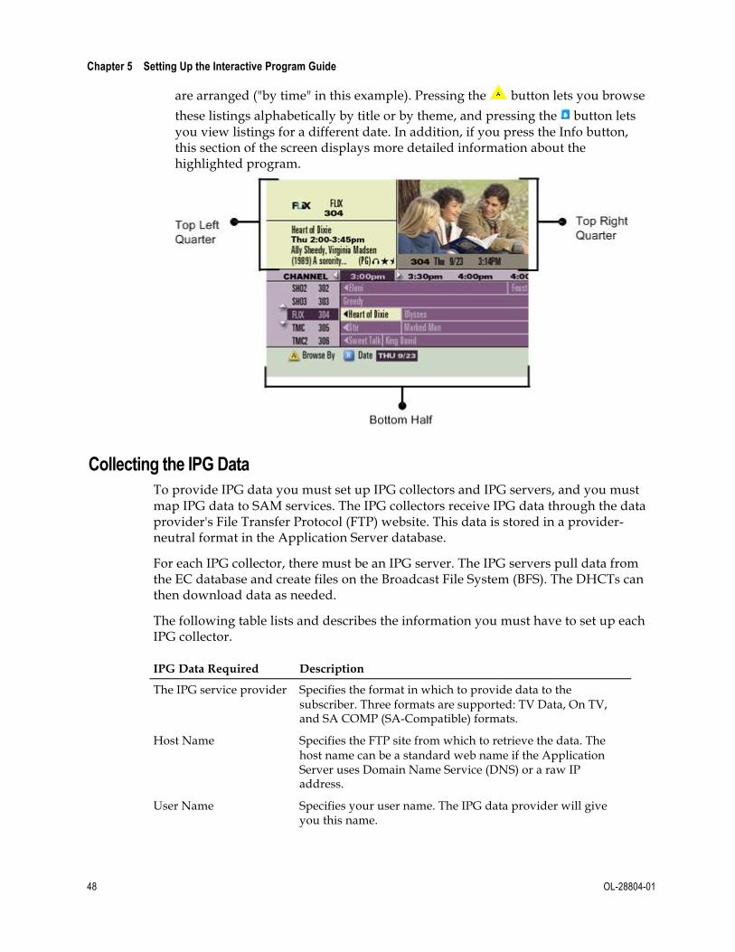
¾ Subscribers can access the IPG by pressing the Guide button on the DHCT remote control, and then scrolling through the list. When you press the Guide button, the picture on the current channel reduces to fit one-quarter of the television screen and appears in the upper right corner of the screen, as shown in the following example.
Areas of the IPG The IPG can be divided into three areas:
¾ Top Left Quarter: The top left corner includes the channel number (304), SAM short description (FLIX), and the channel logo of the highlighted program. This section contains detailed information about the current channel, including the full channel name, the start and end time of the current program, and a description of the program. The description may appear truncated due to screen limitations, but you can always access the full program description by pressing the Info button on the remote control.
Note: Space in this section is also available for an optional Multiple System Operator (MSO) logo. For instructions on positioning your logo, see Positioning Your Logo on the Main Screen of the IPG (on page 61).
¾ Top Right Quarter: The top right corner shows the quarter-screen picture, channel number, date, and time.
¾ Bottom Half: The bottom half of the screen shows the listings for several channels arranged in chronological order. The strip along the bottom of the screen identifies the date for these listings and indicates the way these listings
Chapter 5 Setting Up the Interactive Program Guide
48 OL-28804-01
are arranged ("by time" in this example). Pressing the button lets you browse
these listings alphabetically by title or by theme, and pressing the button lets you view listings for a different date. In addition, if you press the Info button, this section of the screen displays more detailed information about the highlighted program.
Collecting the IPG Data To provide IPG data you must set up IPG collectors and IPG servers, and you must map IPG data to SAM services. The IPG collectors receive IPG data through the data provider's File Transfer Protocol (FTP) website. This data is stored in a provider-neutral format in the Application Server database.
For each IPG collector, there must be an IPG server. The IPG servers pull data from the EC database and create files on the Broadcast File System (BFS). The DHCTs can then download data as needed.
The following table lists and describes the information you must have to set up each IPG collector.
IPG Data Required Description
The IPG service provider Specifies the format in which to provide data to the subscriber. Three formats are supported: TV Data, On TV, and SA COMP (SA-Compatible) formats.
Host Name Specifies the FTP site from which to retrieve the data. The host name can be a standard web name if the Application Server uses Domain Name Service (DNS) or a raw IP address.
User Name Specifies your user name. The IPG data provider will give you this name.

Before You Begin
OL-28804-01 49
IPG Data Required Description
Password Specifies your password. The IPG data provider will give you this password.
Pickup Directory or Data file location
Specifies the directory from which to retrieve data files. The IPG data provider will give you this directory.
File Template Specifies the naming convention of the file to be retrieved.
Collection Time Specifies the time that the IPG collector will collect new data from the data provider
Service Names Specifies the service names used by the content provider.
Logo File If using a logo, the logo file must be present on the EC. For more information, see Adding a File Containing Your Company's Logo to the BFS (on page 60).

Chapter 5 Setting Up the Interactive Program Guide
50 OL-28804-01
Set Up the IPG The process for setting up IPG services includes the following tasks:
¾ Selecting languages that subscribers can choose to display IPG data
¾ Setting up the IPG servers for each language
¾ Setting up IPG collectors for each language
¾ Setting up the IPG services
This section also includes procedures to modify and delete IPG Service names.
If you provide IPG data in foreign languages, you must set up the languages for the IPG data before you set up the IPG. When you first install your system, the IPG is available in at least one language. For the EC to allow you to create additional IPG servers and collectors, you must first select the languages that you offer.
SR 2.5 and later, SR 6.0 and later, and SR 4.0 and later provide support for IPG data in English, French, Spanish, and Japanese. For detailed instructions on setting up support for foreign languages, see Set Up Supported Languages (on page 12).
Setting Up the IPG Server The IPG server is not a physical server. Instead, it is a process named ipgServer that resides on the Application Server. The IPG server uses the IPG information in the database to create IPG data files. The DBDS uses these IPG data files to display program information in the IPG.
Perform the following steps to set up IPG servers:
1 Choose Server Applications > IPG. The IPG Server List window opens.
2 Click Add Server. If you selected a language that does not yet have an IPG server, the Set Up IPG Server window opens.
Note: If all languages already have IPG servers, a message appears to tell you that no languages were found.
3 From the Language drop-down list, choose the desired language.
Note: The Supported Languages that you selected earlier appear in the list.
4 Type the appropriate information for the following fields:
¡ In the Produce Data for field, type the number of days for which you want to produce IPG data (up to 28).
¡ Type 2 in the Send Schedule File Out-of-band for field.
CAUTION:
The BFS requires a lot of bandwidth to send IPG data out of band. If you schedule out-of-band data for more than 2 days, you may cause the BFS Server to function incorrectly and disrupt service to subscribers.

Set Up the IPG
OL-28804-01 51
5 Click Save. The IPG Server List window opens again and lists the new IPG language server that you have just added.
Editing IPG Servers Perform the following steps to edit an existing IPG server:
1 In the main window, choose Server Applications > IPG. The IPG Server List window opens.
2 Choose the IPG server whose settings you want to edit. Then click Edit. A message reminds you that your changes will not take effect unto you restart the IPG server.
3 Click OK. The message disappears and the Edit IPG Server window opens for the server that you selected.
4 Edit the fields in this screen as necessary:
¡ Produce Data For (Days): The typical choice is 7
¡ Send Schedule File Out-of-band for (Days): The typical choice is 2
¡ Maximum Size of each description file (KB): The typical choice is 24
CAUTION:
The BFS requires a lot of bandwidth to send IPG data out of band. If you schedule out-of-band data for more than 2 days, you may cause the BFS Server to function incorrectly and disrupt service to subscribers.
5 Click Save.
6 Now that you have edited the settings for this server, stop and restart the ipgServer process for the changes to take effect. For assistance, see Stopping and Restarting a Server Process (on page 52).
Chapter 5 Setting Up the Interactive Program Guide
52 OL-28804-01
Stopping and Restarting a Server Process If you changed the settings of an existing server process, you must stop and restart the server process for your changes to take effect.
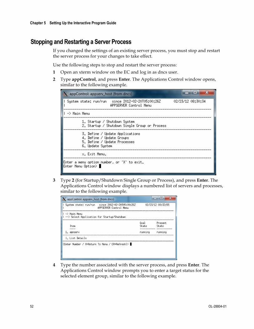
Use the following steps to stop and restart the server process:
1 Open an xterm window on the EC and log in as dncs user.
2 Type appControl, and press Enter. The Applications Control window opens, similar to the following example.
3 Type 2 (for Startup/Shutdown Single Group or Process), and press Enter. The
Applications Control window displays a numbered list of servers and processes, similar to the following example.
4 Type the number associated with the server process, and press Enter. The
Applications Control window prompts you to enter a target status for the selected element group, similar to the following example.

Set Up the IPG
OL-28804-01 53
5 Type e (to display groups) and press Enter.
6 Type 4 to select the PPV processes and press Enter.
7 Type 1 (for stopped) and press Enter. The Applications Control window
refreshes.
Note: The Applications Control window refreshes in real time, or you can press Enter to force a refresh.
8 Wait until Present State of the server process indicates stopped.

Chapter 5 Setting Up the Interactive Program Guide
54 OL-28804-01
9 To restart the group, type 1 to select the PPV processes and press Enter.
10 Type 2 (for running) and press Enter. The Applications Control window
refreshes.
Note: The Applications Control window refreshes in real time, or you can press Enter to force an immediate refresh.
11 Wait until Present State of the server process indicates running.
12 Follow the on-screen instructions to return to the main menu and exit from the appControl utility.
Setting Up the IPG Collector The IPG collector is a process that resides on the Application Server. The IPG collector automatically runs once a day to retrieve IPG data from the IPG data provider.
Perform the following steps to set up IPG collectors:
1 In the IPG Server List window, select the language server that you want to set up.
2 Click Add IPG Collector. The Add IPG Collector window opens, similar to the following example.
3 Complete all the fields by typing the required information, and click Save.

Set Up the IPG
OL-28804-01 55
Important: Leave the Max Long Description Length set to its default value of 240.
Notes:
¡ The video service provider and the IPG data provider supply all the information for these fields, for example, the user name and password, file template, and retrieval directory. The server updates data sent to DHCTs at midnight. Therefore, the collection time should be set as late as possible, but early enough for collection to finish before midnight.
¡ When you set up the IPG collector, it is a good idea to ping the IPG provider's site to make sure that you can connect to the provider's site.
¡ Occasionally, a ping may not work. In this instance, use the command ftp <site IP address or site name> to verify that the site can communicate with the IPG data provider.
4 In the Password Prompt window that opens, retype the password, and then click Continue. The system confirms the password, and then the IPG Server List window opens again.
Setting Up IPG Services After setting up the languages, IPG server, and IPG collector, you are ready to set up the IPG Service. Perform the following steps to set up IPG Services.
Note: To set up IPG Services, you will use the service name list from your content provider and map the service names to SAM Service IDs.
1 In the IPG Server List window, click the IPG Services. The IPG Service List window opens.
2 Click Add. The Create IPG Service window opens.
3 Type the IPG Provider Service Name and the SAM Service ID.
Notes:
¡ The SAM Service ID is the ID number assigned by the EC when the service was registered with the SAM. For more information on registering services with the SAM, refer to your online help.
¡ Service IDs for all services are shown in the SAM Services List window.

Chapter 5 Setting Up the Interactive Program Guide
56 OL-28804-01
¡ For each PPV service that you set up, you must enter both the PPV service and the Event Use service in the IPG service list. If you do not enter both services, event information will be missing from the IPG grid (which requires the PPV service ID) or the PPV purchase barker (which requires the Event Use service ID).
4 Click Save.
Modifying an IPG Service Name Perform the following steps to modify an IPG service name.
Important: The IPG service names should match the names that your data provider uses in the IPG collector file.
1 In the IPG Service List window, highlight the row of the desired IPG service.
2 Make changes to the IPG Provider Service Name, and click Save.
Note: You can only change the IPG Provider service name. You cannot change the SAM service ID.
Deleting an IPG Service Name Perform the following steps to delete an IPG service name:
1 Click Service.
2 In the IPG Service List window, choose the IPG service that you want to delete.
3 Click Delete. A message prompts you to confirm that you want to delete the current item.
4 Click Yes to confirm that you want to delete the IPG service name.

Add IPG Data Manually
OL-28804-01 57
Add IPG Data Manually Usually, your site receives program information from an IPG data provider and passes that data to the IPG without altering the information at all. However, in some cases, no data is provided. This is typically the case for local access channels. To provide subscribers with IPG data in these instances, add the IPG data manually by following the directions explained in this section.
Overview of Adding IPG Data Manually To provide subscribers with IPG data when no data has been provided by the IPG data provider, perform the following steps to manually add IPG data to the service.
1 Create an IPG service for the missing data.
Note: For assistance, see Creating an IPG Service from an Existing SAM Service (on page 57).
2 Map the service to an appropriate SAM service.
Note: For assistance, see Creating an IPG Service from an Existing SAM Service (on page 57).
3 Add IPG data for the service that you created.
Note: For assistance, see Manually Adding Data to an IPG Service.
Creating an IPG Service from an Existing SAM Service Complete these steps to create an IPG service so that you can manually add data to the service.
1 In the main window, choose Server Applications > IPG. The IPG Server List window opens.
2 Click IPG Services. The IPG Services List window opens.
3 Click Add. The Create IPG Service window opens, similar to the following example.
4 Complete these steps to enter data in the Create IPG Service window:
¡ In the IPG Provider Service Name field enter a name for the new service that is unique and does not match any of the names provided by your IPG service provider. For example, you might use "localdata1" to indicate that this is data for a local access channel.

Chapter 5 Setting Up the Interactive Program Guide
58 OL-28804-01
Note: You can enter up to 12 characters in this field.
¡ In the SAM Service ID field, enter the number of the SAM service that you want to map to this IPG data.
5 Click Save. The service that you created is added to the window.

Add Your Company's Logo to the Main IPG Screen
OL-28804-01 59
Add Your Company's Logo to the Main IPG Screen Each time subscribers tune to the IPG, remind them who provides this service by placing your company's logo on the main screen of the IPG. Adding a file containing your company's logo to the BFS causes the logo to appear on the main screen of the IPG. You can also use the MSO Logo Position option to position the logo to either the left or right of the channel number.
This section describes how to add a file containing your company's logo to the BFS and how to position the logo on the main screen of the IPG.
Logo Positions The following screens show an example of the logo positions.

Chapter 5 Setting Up the Interactive Program Guide
60 OL-28804-01
Adding a File Containing Your Company's Logo to the BFS To add a file containing your company's logo to the BFS, perform the following steps:
1 Has the video service provider's logo been placed on the OSM data carousel?
¡ If yes, go to Step 5.
¡ If no, open an xterm window on the EC.
2 Type cd /dvs/resapp/logos and press Enter. The system makes /dvs/resapp/logos the working directory.
3 Copy the file containing the logo from the directory where it is currently stored to/dvs/resapp/logos.
4 Type exit and press Enter. The xterm window closes.
5 In the main menu, choose EC > OS (under the DHCT Provisioning section of the Home Element Provisioning area). The DHCT OS List window opens.
6 Is there an entry in the DHCT OS list named msologo.rle?
¡ If yes, select msologo.rle, then click File and choose Delete to delete it.
¡ If no, go to Step 9.
7 Click Add. The Add DHCT OS window opens.
8 Click Select beside the Source File field. The Select OS File window opens.
9 In the Directories list on the left, click twice to select the /dvs/resapp/logos directory. The files contained in the /dvs/resapp/logos directory appear in the Files list on the right.
10 In the Files list, select the RLE file containing the logo that you want to appear in the Recorded List. The full path of the RLE file that you selected appears in the Selection field.
11 Click OK. The Select OS File window closes and the RLE file that you selected appears in the Source File field in the Add DHCT OS window.
12 In the Description field, type IPG Logo.
13 In the Destination field, type bfs:///osm/msologo.rle.
14 For Format, choose Out-of-Band File.
15 Click Save to save the logo file to the OSM data carousel. After the set-top box reboots, the Application Server client displays the logo in the Recorded List.
Add Your Company's Logo to the Main IPG Screen
OL-28804-01 61
Positioning Your Logo on the Main Screen of the IPG To position your logo on the main screen of the Interactive Program Guide, perform the following steps:
1 In the main window of the EC, click the Server Applications tab.
2 Click DHCT Config. The DHCT Configure Prompt window opens.
3 Choose Global. The Set Up Global DHCT Configuration window opens.
4 Click the IPG tab. The IPG tab appears in the forefront.
5 For the MSO Logo Position option, choose either Left or Right to place your logo either to the left or to the right of the channel number on the Interactive Program Guide.
6 Click Save. The logo appears either to the left or right of the channel number on the Interactive Program Guide.

Chapter 5 Setting Up the Interactive Program Guide
62 OL-28804-01
Configurations That Enhance Your Subscribers' Experience
Overview Explorer DHCTs use a standard set of default parameters that define the way they operate and affect subscribers' experience with the Application Server.
Creating DHCT Configurations Explorer DHCTs use a standard set of default parameters that define the way they operate and affect subscribers' experience with the Application Server. You can create customized sets of these parameters (called DHCT configurations) and apply different DHCT configurations to all DHCTs in your network, to all DHCTs in a hub, or to a single DHCT.
For assistance configuring the Application Server, see Enhancing Your Subscribers' Experience: SARA Configurable Options (part number 78-4002178-01).
For assistance configuring DVR or DVD features, see DVR Configuration Guide (part number 78-4011411-01).

IPG Memory Usage Settings
OL-28804-01 63
IPG Memory Usage Settings
Overview This section describes IPG Memory Usage settings, which allow you to fine tune how the IPG utilizes memory. These adjustments can be made on a site basis or (for testing purposes) on a hub basis. Adjusting these settings may enable you to maximize memory usage, especially on set-top boxes with lower memory.
IPG Memory Usage Settings You'll find the settings for IPG Memory Usage on the bottom portion of the IPG tab, similar to the following example.
To adjust how the IPG utilizes memory, change the default settings in the Memory Usage area.
The IPG Memory Usage fields display the following information about how the IPG utilizes memory.

Chapter 5 Setting Up the Interactive Program Guide
64 OL-28804-01
Field Name Description and Possible Values
Leave Largest Contiguous Free KB
The value in this field indicates, in kilobytes, the minimum amount of contiguous free memory ("largest contiguous free block") that the IPG daemon in the set-tops must see available in order to download IPG files in the background.
Note: This field requires a minimum value of 50 KB.
Default setting: 512 KB
Additional Total Free in Excess of Largest Contiguous KB
The value in this field indicates, in kilobytes, the minimum amount of additional free memory above and beyond the largest contiguous block that the IPG daemon in the set-tops must see available to download IPG files in the background. For example, if Leave Largest Contiguous Free KB is set to 512 and Additional Total Free in Excess of Largest Contiguous KB is set to 256, then there must be at least 768 KB of total free memory.
Default setting: 256 KB
Notes:
¾ These two settings are used in combination by the DHCT's IPG Daemon. If either the "largest contiguous free" block of memory or "total free" memory have fallen below the thresholds, additional files will not be downloaded in the background unless the available memory grows back above the threshold.
¾ These two thresholds do not restrict background loading of the grid nor description data files for the current or next day unless they are configured as "Automatic Priority-Based Purging".
¾ The above two thresholds do not restrict loading of files when requested by the IPG UI (user-initiated).
¾ The above thresholds are examined before downloading files, therefore if the desire is to ensure that the IPG always leaves a certain amount of memory free, then the thresholds need to be adjusted to accommodate the typical largest size of the site's IPG grid data files. In other words, if the desire is to ensure there is at least 512 KB contiguous free after loading data, and the site's grid data files are at most 300 KB (for example), then the value needs to be set to 512+300, or 812 KB.
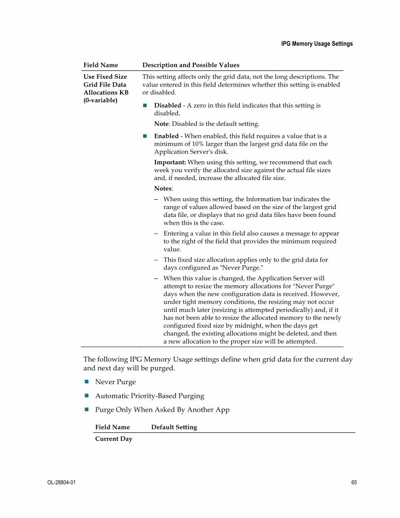
IPG Memory Usage Settings
OL-28804-01 65
Field Name Description and Possible Values
Use Fixed Size Grid File Data Allocations KB (0-variable)
This setting affects only the grid data, not the long descriptions. The value entered in this field determines whether this setting is enabled or disabled.
¡ Disabled - A zero in this field indicates that this setting is disabled.
Note: Disabled is the default setting.
¡ Enabled - When enabled, this field requires a value that is a minimum of 10% larger than the largest grid data file on the Application Server's disk.
Important: When using this setting, we recommend that each week you verify the allocated size against the actual file sizes and, if needed, increase the allocated file size.
Notes:
– When using this setting, the Information bar indicates the range of values allowed based on the size of the largest grid data file, or displays that no grid data files have been found when this is the case.
– Entering a value in this field also causes a message to appear to the right of the field that provides the minimum required value.
– This fixed size allocation applies only to the grid data for days configured as "Never Purge."
– When this value is changed, the Application Server will attempt to resize the memory allocations for "Never Purge" days when the new configuration data is received. However, under tight memory conditions, the resizing may not occur until much later (resizing is attempted periodically) and, if it has not been able to resize the allocated memory to the newly configured fixed size by midnight, when the days get changed, the existing allocations might be deleted, and then a new allocation to the proper size will be attempted.
The following IPG Memory Usage settings define when grid data for the current day and next day will be purged.
¾ Never Purge
¾ Automatic Priority-Based Purging
¾ Purge Only When Asked By Another App
Field Name Default Setting
Current Day
Chapter 5 Setting Up the Interactive Program Guide
66 OL-28804-01
Data Grid Never Purge
Important: This setting must not be more purgeable than the setting for the Current Day Descriptions, the setting for Next Day Data Grid, or the setting for Next Day Descriptions.
Descriptions Purge Only When Asked By Another App
Important: This setting must not be more purgeable than the setting for the Next Day Data Descriptions.
Next Day
Data Grid Never Purge
Important: This setting must not be more purgeable than the setting for the Next Day Descriptions.
Descriptions Automatic Priority-Based Purging
Important: This setting must not be more purgeable than the setting for the Current Day Data Grid.
Automatic Purging of IPG Data From time to time, the operating system may purge IPG descriptions or future grid data in order to fulfill a more urgent memory allocation request. Each IPG memory cache is marked with a purge priority, which determines which information should be purged first. Important data is marked with a higher number, so the operating system purges data with lower numbers first. The memory usage scheme is as follows:
¾ Data for the current day is always locked in memory, so it is never purged.*
¾ Data for the next day is always locked in memory, so the OS cannot purge it.* However, SARA will purge this data as a last resort before unloading apps to get memory.
¾ Descriptions for the current day can be purged at priority 3 when idle or priority 8 when the IPG is active.
¾ Descriptions for the next day can be purged at priority 1 when idle or priority 6 when the IPG is active.
¾ All grid data for future days can be purged at priority 0 when idle or priority 5 if the IPG is active. This data is locked and cannot be purged while the IPG is displaying data for that day.
¾ All descriptions for future days can be purged at priority 0 when idle or priority 5 when the IPG is active. (When idle, all future days descriptions should already be automatically purged by the IPG daemon.)
*This is true for older Application Servers; however, newer Application Servers give you additional flexibility. In the EC IPG GUI, you can now set Current and Next Day to allow purging.

Adjust How DHCTs Use IPG Memory
OL-28804-01 67
Adjust How DHCTs Use IPG Memory This section provides instructions for sending IPG Memory Usage settings to DHCTs. Sending these settings to DHCTs allows you to fine tune how DHCTs use IPG memory. You can use either of the following methods to send these settings to DHCTs:
¾ Global: Sends the settings to all DHCTs in your network.
¾ Hub-Specific: Sends the settings to DHCTs in a specific hub. This method allows you to test the settings on DHCTs in the headend before applying the settings to all DHCTs in your network.
This section also provides instructions for modifying settings for a hub and for changing hub settings to global settings.
Sending IPG Memory Usage Settings to All DHCTs in a Specific Hub Sending settings to all DHCTs in a hub requires that you first enable the settings for use on a hub-specific basis. Once hub-specific settings are enabled, you can configure each setting for any hub in your network. Until you enable these settings, they will be unavailable for you to configure and send to DHCTs in a specific hub.
To Enable Hub-Specific Memory Usage Settings Follow these instructions to enable hub-specific IPG Memory Usage settings:
1 In the main window, choose Server Applications > DHCT Config. The DHCT Configure window opens.
2 Click Hub. The DHCT Configure window displays all of the hubs in your network along with their IDs and configurations.
3 Click Select Hub-Specific Items. The Select Hub Specific Items window opens.
4 Click the IPG tab. The IPG tab moves to the forefront and displays the settings that are available for selection.

Chapter 5 Setting Up the Interactive Program Guide
68 OL-28804-01
5 In the Memory Usage area of the tab, select each setting that you want to be able to configure at the hub level.
6 Click Save. These selections are made available to all hubs and the Select Hub-
Specific Items window closes. You can now configure and send IPG Memory Usage settings to DHCTs in a hub. See To Send IPG Memory Usage Settings to All DHCTs in a Hub (on page 68).
To Send IPG Memory Usage Settings to All DHCTs in a Hub After you have enabled hub-specific IPG Memory Usage settings, follow these instructions to configure and send them to all DHCTs in a hub.
1 In the main screen, click the Server Applications tab.
2 Click DHCT Config. The DHCT Configure Prompt window opens.
3 Click Hub. The DHCT Configure Prompt window displays all of the hubs in your network along with their IDs and configurations.
Note: The Configuration field indicates whether the hub is set to the standard, Global configuration or whether it uses a Hub-Specific configuration.
4 Select the hub whose IPG Memory Usage settings you want to configure and click New Hub-Specific. The Set Up Hub DHCT Configuration window opens.
5 Click the IPG tab. The IPG tab moves to the forefront and displays the default Memory Usage settings.
6 Are the Memory Usage settings available?
¡ If yes, continue with the next step in this procedure.
Adjust How DHCTs Use IPG Memory
OL-28804-01 69
¡ If no, the settings are dimmed because they have not been enabled for hub-specific configurations. See To Enable Hub-Specific Memory Usage Settings (on page 67).
7 Enter the settings appropriate for this hub.
Note: For an explanation of Memory Usage settings, see IPG Memory Usage Settings (on page 63).
8 When finished, click Save. The Application Server sends the configuration to all of the DHCTs in the hub that you specified. Changes should be made to DHCTs within a few minutes.
9 Do you want to send this configuration to another hub in your network?
¡ If yes, repeat Steps 4 to 8 for each hub that you want to change.
¡ If no, you have successfully sent IPG Memory Usage settings to DHCTs in all hubs that you require.
Modifying IPG Memory Usage Settings for DHCTs in a Specific Hub If for any reason you need to change Memory Usage settings for DHCTs in a specific hub, follow these instructions.
1 In the main window, click the Server Applications tab.
2 Click DHCT Config. The DHCT Configure Prompt window opens.
3 Click Hub. The DHCT Configure Prompt window displays all of the hubs in your network along with their IDs and configurations.
4 Select the hub whose IPG Memory Usage settings that you want to change and click Edit. The Set Up DHCT Configuration window for the hub that you selected opens.
5 Click the IPG tab. The IPG tab moves to the forefront.
6 Change the Memory Usage settings you desire.
7 When finished, click Save. The Application Server sends the configuration to all of the DHCTs in the hub that you specified. Changes should be made to DHCTs within a few minutes.
Sending IPG Memory Usage Settings to All DHCTs in Your Network Once you have completed testing the Memory Usage settings on the DHCTs in your headend, follow these instructions to send these settings globally to all DHCTs in your network that do not receive hub-specific settings. After these settings are applied globally, you will be able to change any hub-specific settings to those of the global settings if you wish.
1 In the main window, click the Server Applications tab.
2 Click DHCT Config. The DHCT Configure window opens.
3 Choose Global. The Set Up Global DHCT Configuration window opens.

Chapter 5 Setting Up the Interactive Program Guide
70 OL-28804-01
4 Click the IPG tab. The IPG tab moves to the forefront and displays the default Memory Usage settings.
5 Enter the settings appropriate to your network.
Note: For an explanation of Memory Usage settings, see IPG Memory Usage Settings (on page 63).
6 When finished, click Save. The Application Server sends these settings to all DHCTs in your network that do not receive hub-specific settings. Changes should be made within a few minutes.
Note: These changes do not affect DHCTs that receive hub-specific configurations.
Changing a Hub-Specific Configuration to a Global Configuration Once you have completed testing the Memory Usage settings on the DHCTs in your headend, follow these instructions to send these settings globally to all DHCTs in your network that do not receive hub-specific settings. After these settings are applied globally, you will be able to change any hub-specific settings to those of the global settings if you wish.
1 In the main window, click the Server Applications tab.
2 Click DHCT Config. The DHCT Configure Prompt window opens.
3 Click Hub. The DHCT Configure Prompt window displays all of the hubs in your network along with their IDs and configurations.
4 Select the hub that you need to change from Hub-Specific to Global configuration and click Delete. A message asks if you are sure that you want to delete the hub-specific configuration.
5 Click Yes to delete the hub-specific configuration.

Selecting the Number of Days of IPG Data to Produce
OL-28804-01 71
Selecting the Number of Days of IPG Data to Produce
You can set the IPG to produce up to 28 days of data. Follow these steps to specify how many days of data the IPG should produce.
1 From the EC Administrative Console, click the Server Applications tab.
2 Click IPG. The IPG Server List window opens.
3 Select the server that you want to modify, then click Edit. An information message appears.
4 Click OK to acknowledge the information message. The Edit IPG Server window opens, similar to the following example.
5 In the Produce data For field, type the number of days of IPG data that you want
to download.
6 Click Save to save the changes, then click Cancel to close the window.
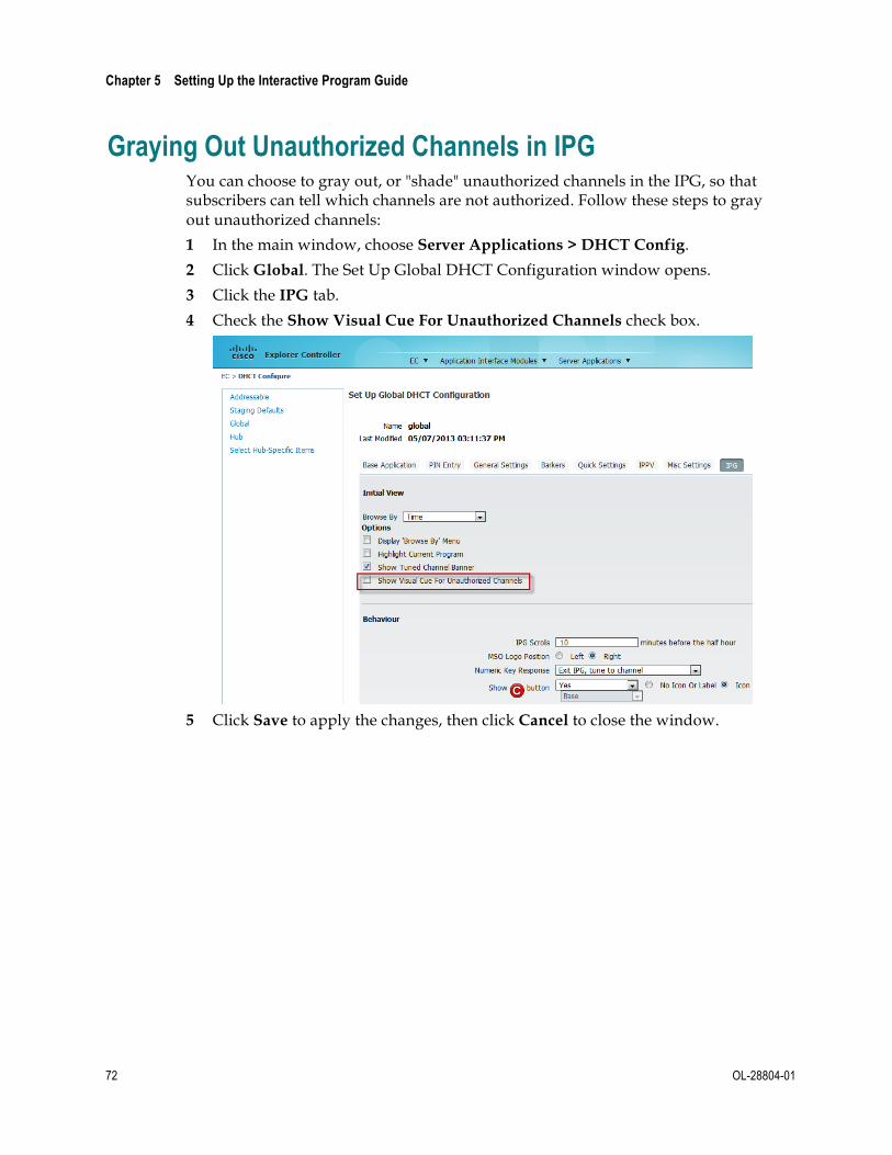
Chapter 5 Setting Up the Interactive Program Guide
72 OL-28804-01
Graying Out Unauthorized Channels in IPG You can choose to gray out, or "shade" unauthorized channels in the IPG, so that subscribers can tell which channels are not authorized. Follow these steps to gray out unauthorized channels:
1 In the main window, choose Server Applications > DHCT Config.
2 Click Global. The Set Up Global DHCT Configuration window opens.
3 Click the IPG tab.
4 Check the Show Visual Cue For Unauthorized Channels check box.
5 Click Save to apply the changes, then click Cancel to close the window.

OL-28804-01 73
Virtual channels are channels that display text (using a special limited HTML command set) when a subscriber tunes to them. The file that contains the information must be on the Application Server. This information may include announcements of civic organizations, community organizations, or local businesses.
Video service providers use this service to provide a variety of information to subscribers. Virtual channels are typically available to all subscribers. These are not "real" RF channels. They allow the cable operators to create text channels (usually information channels) without using RF spectrum.
The Virtual Channel Server (VCS) interacts with the BFS, SAM, and Channel Map to provide services to the DHCTs that display text information. This section describes how to configure the VCS BFS, how to build or edit a virtual channel source file, and how to set up virtual channels and register them with the SAM and BFS to make the service available to subscribers.
Important: Building and editing a virtual channel source file requires a thorough knowledge of HTML. The instructions provided in this chapter are no substitute for a thorough knowledge of HTML.
6 Chapter 6 Setting Up a Virtual Channel Service
In This Chapter ¡ Configure the VCS Broadcast File System (BFS) .............................. 74 ¡ Build a Virtual Channel Source File ................................................... 77 ¡ Set Up a Virtual Channel Service ....................................................... 80

Chapter 6 Setting Up a Virtual Channel Service
74 OL-28804-01
Configure the VCS Broadcast File System (BFS) Typically during a system upgrade, the installer configures the BFS by adding a virtual channel server to the BFS. However, if this procedure was not performed at the time of upgrade, use the following procedures to check or configure a BFS server for the virtual channel service.
In earlier releases of the Application Server, virtual channel files could only exist on BFS Source ID 2 (inband) with other OSM files such as PowerTV and the Application Server ROM. With recent modifications to the arrangement of alternating BFS files, small virtual channel server files now circulate very slowly, and leave the virtual channels practically useless. To resolve this issue, you must move the virtual channel files to a new source. Doing so allows the BFS to update the information it sends to the DHCTs and the virtual channels can then appear faster.
Important Note for Multiple-Site (RCS-Enabled) Systems: Manually setting up any BFS server or source for the Application Server's use must be done for the "AllSites" site only, and not for any other individual sites in your system. Otherwise, the server and source will fail.
Procedure at a Glance To configure the BFS for the virtual channel server, complete the following steps.
Note: For detailed instructions on adding a VCS application to the BFS, see Adding and Removing Applications on the BFS For System Release 2.5/3.5 and 4.0 (part number 78-4011048-01).
1 Create a new digital source with the following characteristics in the Source List window:
¡ Source Name: You can enter any name that helps you to remember the service that this source provides. For example, you might use "VCS BFS Source."
¡ Source ID: An unused even number that is greater than 200.
Note: To define these characteristics, display the Set Up Source window by following this quick path: main window > System Provisioning tab > Source > File > New.
2 Create a new source definition with the following characteristics in the Source Definition List window:
¡ Session ID: 00:00:00:00:00:00 plus the number used for the Source ID
¡ Session Definition: BFS
Note: To define these characteristics, display the Set Up Digital Source Definition window, by following this quick path: main window > System Provisioning tab > Source > [Select Source] > File > Source Definitions > File > New Digital.
3 Add a source with the following characteristics to the Sources tab of the BFS Administration window:
Configure the VCS Broadcast File System (BFS)
OL-28804-01 75
Important: Multi-site (RCS-enabled) systems should use the All Sites tool to add a source to the Sources tab on the Site AllSites BFS Administration window.
¡ Source Name: Use the same name that you used for the Source Name in Step 1
¡ Source ID: Use the same number that you used for the Source ID in Step 1
¡ Source Type: BFS
¡ Transport Type: ASI In-band or In-band
¡ Data Rate: 0.5 Mbps or less
Note: You may also use a value as low as 0.1 Mbps. The maximum rate that you can enter for inband data is 2.00 Mbps. For assistance, see Recommendations for Data Carousel Rate Management Technical Bulletin (part number 700-716377-01).
¡ Block Size and Indication Interval: Use the default values
¡ Selected Hosts: Select the host according to your system configuration:
– For single-site systems, select dncsatm
– For multiple-site (RCS-enabled) systems, select AllSitesHost
Note: To define these characteristics, display the Set Up BFS Source window by following the quick path for your system configuration:
– Single-Site System: main window > Application Interface Modules tab > BFS Admin > Sources tab > File > New
– Multi-Site System: main window > Application Interface Modules tab > BFS Admin > File > All Sites > Sources tab > File > New
4 Add a server with the following characteristics to the Servers tab in the BFS Administration window:
Important: Multi-site (RCS-enabled) systems should use the All Sites tool to add the server with the following characteristics to the Servers tab in the Site AllSites BFS Administration window.
¡ Server Name: VCS
¡ Selected Sources List: VCS Source
Note: To define these characteristics, display the Authorize BFS Server window by following the quick path for your system configuration:
¡ Single-Site System: main window > Application Interface Modules tab > BFS Admin > Servers tab > File > New
¡ Multi-Site System: main window > Application Interface Modules tab > BFS Admin > File > All Sites > Servers tab > File > New
5 Register the server with the BFS Client by adding a server with the following characteristics to the Broadcast File Server List window:
¡ Server Name: VCS
¡ Mode: One-way

Chapter 6 Setting Up a Virtual Channel Service
76 OL-28804-01
¡ Selected Sources: VCS
Note: To define these characteristics, display the Set Up Server window by following the quick path for your system configuration:
¡ Single-Site Systems: main window > Application Interface Modules tab > BFS Client > File > New Server
¡ Multi-Site Systems: main window > Application Interface Modules tab > BFS Client > File > All Sites > File > New Server
6 Configure the new BFS server source ID on the virtual channel server. For assistance, go to Configuring the New BFS Server Source ID (on page 76).
Configuring the New BFS Server Source ID The final step in configuring the BFS source ID is to configure the new BFS server source ID on the server. Perform the following steps to configure the BFS server source ID.
1 On the main screen, click Server Applications > VCS. The VCS List window opens.
2 Click Configure. The Configure VCS window opens.
3 Verify that the number that appears in the BFS Server Source ID field matches
the BFS server source ID you created earlier, then click OK to return to the VCS List window.
4 Click either Save or Cancel to return to the VCS List window.
5 Use appControl to stop and restart the VCS group. Refer to Stopping and Restarting a Server Process (on page 52) for more information.
Approximately 1 minute after the server restarts, the BFS sends the updated information to the DHCTs. This update means that the virtual channels take less time to display when a subscriber tunes to the channel.
6 Verify that the virtual channels operate correctly.

Build a Virtual Channel Source File
OL-28804-01 77
Build a Virtual Channel Source File When building a virtual channel source file, you must first complete the following tasks.
1 Create the source HTML files for the virtual channel client to use.
2 Save the source HTML files to the appropriate directory on the Application Server.
Although this section provides procedures for building a source file for a virtual channel, a thorough knowledge of HTML is required to perform these procedures successfully. The instructions provided in this section are no substitute for a thorough knowledge of HTML.
Creating the Source HTML Files These files provide the content for a virtual channel in the same way that a local studio or satellite feed provides content for a clear broadcast. Therefore, by creating the HTML file, you create a source for the virtual channel service.
You can use any HTML editor to create a document that contains the information you want the subscriber to see. However, when formatting the text you can only use the tags in the following table.
Important: The behavior of the Virtual Channel client is unpredictable if you use any tags that do not appear in the following table to create an HTML document. Only these tags are supported because the Application Server client uses the Virtual Channel application (not a standard, full-featured browser) to read the source file.
Tag Meaning
<b></b> Display text between tags as bold text
<big></big> Display text between tags as large text
<br> Insert blank rule (line break)
<br1.5> Insert 1.5 blank rules (1.5 line break)
<center></center> Display text and images between tags as horizontally centered on the line
<img scr="ok.img"> Display the SELECT button
<img scr="a.img"> Display the A button
<img scr="b.img"> Display the B button
<img scr="c.img"> Display the C button
<img scr="settings.img"> Display the SETTINGS button
<font color="white"> Change the font color to white
<font color="black"> Change the font color to black

Chapter 6 Setting Up a Virtual Channel Service
78 OL-28804-01
Tag Meaning
<font color="yellow"> Change the font color to yellow
<table bgcolor="alert"></table> Applies a standard 3-row alert-banner background to the table
<table bgcolor="swirl"></table> Applies a purple swirl graphic to the background of the table
<table bgcolor="none"></table> Applies a transparent background to the table
<tr> Define a table row. (For alert banner background, there must be at least three rows per table)
Example: The following is a sample HTML document with the recommended tags for a Virtual Channel client.
Saving the Source HTML Files After creating the source HTML files using the appropriate tags, you must save the files in the /dvs/appFiles/html directory on the EC. Use the parse utility in the /dvs/appserv/bin directory to verify that the Virtual Channel client can display your files.
Perform the following steps to run the parse utility.
1 Create two directories.
2 Name one good and the other bad.
3 Save them in the /dvs/appFiles/html directory. The following three directories appear for HTML files:
¡ /dvs/appFiles/html
¡ /dvs/appFiles/html/good
¡ /dvs/appFiles/html/bad
Build a Virtual Channel Source File
OL-28804-01 79
4 In an xterm window, type parse [filename] to run the parse utility, where [filename] is the name of the file you want to validate. One of the following results occurs:
¡ If the Virtual Channel can use your HTML file, the parse utility displays the following:
Parsed file <file.html>, no errors found.
Moved the file to <good/file.html>.
¡ If the Virtual Channel cannot use your HTML file, the parse utility displays the following:
Parsed file <file.html>, errors found.
Moved the file to <bad/file.html>.
Please look at <bad/file.err> for details
Note: File.err lists line numbers of any lines of text that use HTML tags not recognized by the Virtual Channel client.

Chapter 6 Setting Up a Virtual Channel Service
80 OL-28804-01
Set Up a Virtual Channel Service
Overview When setting up a virtual channel service, you must first complete the following tasks.
1 Set up the virtual channel service.
2 Place the virtual channel service on the Channel Map.
This section provides procedures for completing these tasks, as well as for modifying a virtual channel configuration, editing a source file, and deleting a virtual channel.
Setting Up the Virtual Channel Service Now that you have created your source HTML file and saved it on your EC for your virtual channels, you are ready to set up your virtual channel service.
Use the following steps to set up virtual channels.
1 On the main screen, click the Server Applications tab.
2 Click VCS. The VCS List window opens.
3 Click Add. The Add VCS window opens.
4 Type the service name, short description, and long description in their respective
fields.
5 In the Data File field, click Select. The Source URL Selection window opens.
Note: You must define the source that the service uses by linking the new service with an HTML file that you created earlier.
6 Browse to the directory and select the HTML file to display on the virtual channel.
Note: We recommend that you save the html files is in /dvs/appFiles/html/good or in one of its subdirectories.
7 Click OK to return to the Add VCS window.
8 Type the logo index in the Logo Index field.
9 Click Save.

Set Up a Virtual Channel Service
OL-28804-01 81
Placing the Virtual Channel on the Channel Map After you set up a virtual channel service, you must place the virtual channel on a channel map. Refer to your online help for more information.
Modifying a Virtual Channel Configuration Use the following steps to modify a virtual channel configuration.
1 On the VCS List window, select the row of the desired service and click Edit.
2 Make the desired changes on the Set Up VCS window, and click Save.
Editing a Source File The source files for virtual channels are links. As a result of editing, the source automatically forces the channel to update on the DHCTs.
Use the following steps to edit a source file.
1 Open the source file in the editor and make the changes you require.
2 Use the parse utility to verify your changes.
3 Check for updated information.
Deleting a Virtual Channel Use the following steps to delete a virtual channel.
1 Select the virtual channel you want to delete in the VCS List window.
2 Click Delete. A message prompts you to confirm that you want to delete the current item.
3 Click Yes to confirm that you want to delete the virtual channel.


OL-28804-01 83
This chapter details the procedures used to manage the Power On Keys, Numeric Keys Power On DHCT, and Power On Channel Selective Override options.
Note: If the Power On Keys option is not selected, then the Power On Keys option is not displayed on the set-top box.
These options let you:
¾ Configure keys on the set-top remote control device to power-on the set-top from standby
¾ Change the power-on channel that is set for most subscribers without affecting subscribers who have chosen a different power-on channel for themselves
Important: The set-top remote control must be in "cable" mode for subscribers to use this feature to power-on the set-top from standby.
7 Chapter 7 Enabling Power On Features
In This Chapter ¡ Set Up Power On Keys ......................................................................... 84 ¡ Configure Power On Keys ................................................................... 85 ¡ Upgrade From AS 3.5 or Earlier ......................................................... 88 ¡ Configure Power On Channel Options ............................................. 89

Chapter 7 Enabling Power On Features
84 OL-28804-01
Set Up Power On Keys You can configure the DHCT to control which buttons will turn on the DHCT, and you can set these as either a Global variable or an Addressable variable
You can set any of the following combinations to power on the DHCT:
¾ Power Key Only
¾ Power and Numeric Keys
¾ Power, Numeric, Channel, and Volume Keys
Note: Channel keys include Channel +/-, LAST, and FAV. Volume keys include Vol +/- and Mute.

Configure Power On Keys
OL-28804-01 85
Configure Power On Keys The Power On Keys feature can be configured in one of two ways:
1 Global
2 Addressable
In Global Configuration, the Power On Keys checkbox on the General Settings tab determines whether the Power On Keys feature is set for Addressable or for Global configuration.
¾ When selected, Power On Keys enables Addressable configuration.
¾ When de-selected, Power On Keys enables Global configuration.
Global Configuration The Global configuration affects all the set-tops in the network.
¾ Keys that can power-on the set-top from standby are set from the Application Server.
¾ The Power On Keys option is not displayed in General Settings on the set-top box.
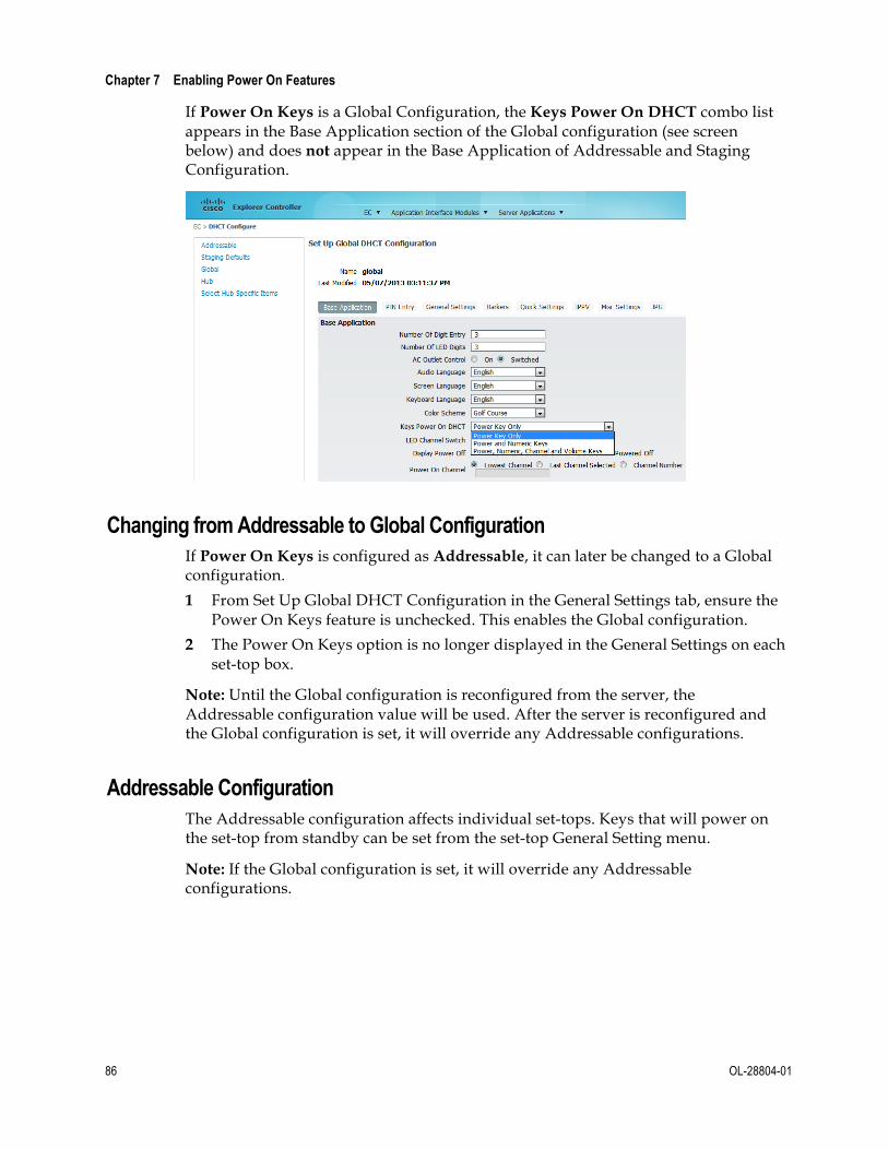
Chapter 7 Enabling Power On Features
86 OL-28804-01
If Power On Keys is a Global Configuration, the Keys Power On DHCT combo list appears in the Base Application section of the Global configuration (see screen below) and does not appear in the Base Application of Addressable and Staging Configuration.
Changing from Addressable to Global Configuration If Power On Keys is configured as Addressable, it can later be changed to a Global configuration.
1 From Set Up Global DHCT Configuration in the General Settings tab, ensure the Power On Keys feature is unchecked. This enables the Global configuration.
2 The Power On Keys option is no longer displayed in the General Settings on each set-top box.
Note: Until the Global configuration is reconfigured from the server, the Addressable configuration value will be used. After the server is reconfigured and the Global configuration is set, it will override any Addressable configurations.
Addressable Configuration The Addressable configuration affects individual set-tops. Keys that will power on the set-top from standby can be set from the set-top General Setting menu.
Note: If the Global configuration is set, it will override any Addressable configurations.
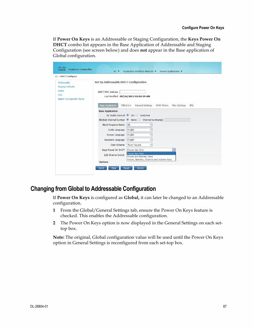
Configure Power On Keys
OL-28804-01 87
If Power On Keys is an Addressable or Staging Configuration, the Keys Power On DHCT combo list appears in the Base Application of Addressable and Staging Configuration (see screen below) and does not appear in the Base application of Global configuration.
Changing from Global to Addressable Configuration If Power On Keys is configured as Global, it can later be changed to an Addressable configuration.
1 From the Global/General Settings tab, ensure the Power On Keys feature is checked. This enables the Addressable configuration.
2 The Power On Keys option is now displayed in the General Settings on each set-top box.
Note: The original, Global configuration value will be used until the Power On Keys option in General Settings is reconfigured from each set-top box.
Chapter 7 Enabling Power On Features
88 OL-28804-01
Upgrade From AS 3.5 or Earlier Important: If you are upgrading from a version earlier than AS 3.6, be aware of the following:
¾ The existing value of Numeric Keys Power On DHCT (this includes Power Key Only, Power and Numeric Keys) is retained as the staging parameter value.
¾ The existing Addressable/Staging>Base Application>Numeric Keys Power On DHCT toggle button has been changed to a Keys Power On DHCT Combo List.
¾ The Power On Keys option is enabled and set to Addressable (not Global) by default.

Configure Power On Channel Options
OL-28804-01 89
Configure Power On Channel Options Some service providers set all of their set-tops to tune to a specific channel (often channel 2) whenever the set-top box is powered on. Other service providers allow their subscribers to choose the channel that they want to see when the set-top box is powered on. These settings are controlled through the Set Up DHCT Configuration window, on the Base Application tab and the General Settings tab.
In SR 4.4.1, you can change the power-on channel that is set for most of your subscribers without affecting the subscribers who have chosen a different power-on channel for themselves.
Configuring Power On Channel Options Globally Follow these steps to configure the power-on channel feature globally:
1 On the main screen, click Server Applications > DHCT Config. The DHCT Configure window opens.
2 Click Global. The Set Up Global DHCT Configuration window opens.
3 Click the General Settings tab.
4 De-select Power On Channel.
Important: Do not click Save yet. Once you click Save, your subscribers can no longer specify a power-on channel from the set-top menu. To minimize this disruption, follow these steps as written.
5 Click the Base Application tab.
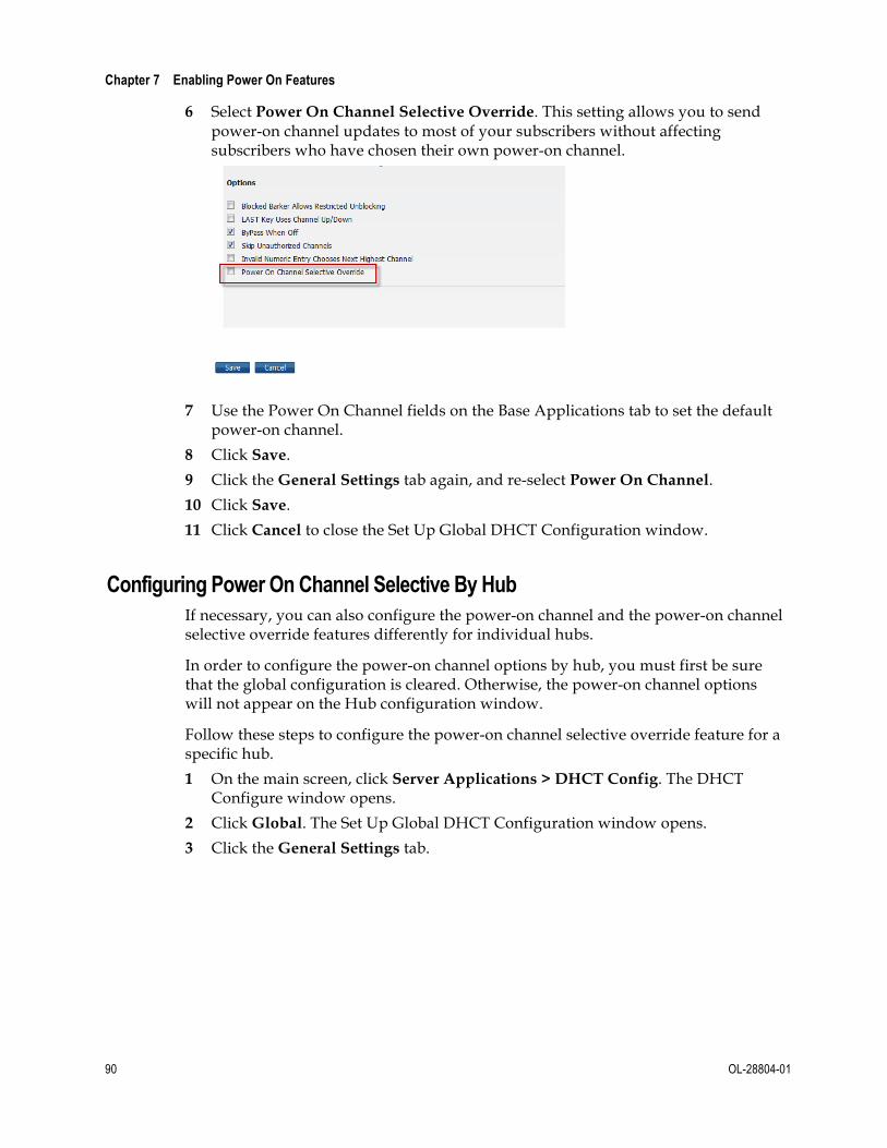
Chapter 7 Enabling Power On Features
90 OL-28804-01
6 Select Power On Channel Selective Override. This setting allows you to send power-on channel updates to most of your subscribers without affecting subscribers who have chosen their own power-on channel.
7 Use the Power On Channel fields on the Base Applications tab to set the default
power-on channel.
8 Click Save.
9 Click the General Settings tab again, and re-select Power On Channel.
10 Click Save.
11 Click Cancel to close the Set Up Global DHCT Configuration window.
Configuring Power On Channel Selective By Hub If necessary, you can also configure the power-on channel and the power-on channel selective override features differently for individual hubs.
In order to configure the power-on channel options by hub, you must first be sure that the global configuration is cleared. Otherwise, the power-on channel options will not appear on the Hub configuration window.
Follow these steps to configure the power-on channel selective override feature for a specific hub.
1 On the main screen, click Server Applications > DHCT Config. The DHCT Configure window opens.
2 Click Global. The Set Up Global DHCT Configuration window opens.
3 Click the General Settings tab.

Configure Power On Channel Options
OL-28804-01 91
4 De-select Power On Channel.
5 Click Save to apply the changes, then click Cancel to close the window.
6 In the DHCT Configure window, click Hub. The DHCT Configure window shows a list of your hubs.
7 Click Select Hub-Specific Items. The Select Hub Specific Items window opens.
8 Click the Base Application tab.
9 Select Power On Channel. This setting allows you to configure the power-on channel options for a specific hub.

Chapter 7 Enabling Power On Features
92 OL-28804-01
10 Click Save to apply the changes and close the window.
11 Click Hub, and select the hub that you want to configure.
12 Does the table indicate that the configuration for that hub is hub-specific?
¡ If yes, click Edit. The Set Up Hub DHCT Configuration window opens.
¡ If no, click New Hub-Specific. The Set Up Hub DHCT Configuration window opens.
13 Click the Base Application tab.
14 Select Power On Channel Selective Override.
15 Use the Power On Channel fields to set the default power-on channel.
16 Click Save to apply your changes, and click Cancel to close the window.
17 Do you want to allow subscribers to change their power-on channel options from the set-top box?
¡ If yes, go to step 19.
¡ If no, then you are finished with this procedure.
18 From the DHCT Configure Prompt window, click Global. The Set Up Global DHCT Configuration window opens.
19 Click the General Settings tab.
20 De-select Power On Channel.
21 Click Save to apply the changes, then click Cancel to close the window.

OL-28804-01 93
The Application Server can track the flow of data messages between the Application Server and other network elements and store those messages in a log file. The process of tracking those data messages is called tracing.
This chapter provides procedures to enable and disable the tracing function and to specify the level of detail that you want to include in the log file.
8 Chapter 8 Enabling Tracing on the Application Server
In This Chapter ¡ Enabling Logging .................................................................................. 94 ¡ View the Log Files ................................................................................. 95

Chapter 8 Enabling Tracing on the Application Server
94 OL-28804-01
Enabling Logging Important: If you set your logging levels too high, you could raise your Application Server load levels to unacceptable levels. You should only adjust these logging levels if you are troubleshooting a specific problem.
Using the applogLvl Utility You can use the applogLvl utility to view and change logging levels from a command line on the Application Server as dncs user in order to support troubleshooting activities. Execute these commands from the /dvs/appserv/bin directory.
The following commands are available:
Command Result
applogLvl Displays the current logging level for all processes.
/export/home/dncs>applogLvl appUIServer +EM +AL +CR +ER +WA -NO -IN -DE -PE -PI -ZIP HCT +EM +AL +CR +ER +WA -NO -IN -DE -PE -PI -ZIP ipgServerEng +EM +AL +CR +ER +WA -NO -IN -DE -PE -PI -ZIP . . .
applogLvl <processname> Displays the current logging level for the specified process.
/export/home/dncs>applogLvl ppvServer ppvServer +EM +AL +CR +ER +WA -NO -IN -DE -PE -PI -ZIP
applogLvl <processname> +<level>
Turns on a logging level for the specified process.
/export/home/dncs>applogLvl ppvServer +NO ppvServer +EM +AL +CR +ER +WA +NO -IN -DE -PE -PI -ZIP
applogLvl <processname> -<level>
Turns off a logging level for the specified process.
/export/home/dncs>applogLvl ppvServer -NO ppvServer +EM +AL +CR +ER +WA -NO -IN -DE -PE -PI -ZIP
applogLvl -h Provides a help output for the applogLvl utility.

View the Log Files
OL-28804-01 95
View the Log Files The Application Server captures various kinds of trace information to various log files. Those log files are stored in two directories: /var/log/dncsLog and /dvs/appserv/tmp.
¾ The files in /var/log/dncsLog only contain error messages and process start/stop messages. The Application Server automatically deletes these log files after three days.
¾ The files in /dvs/appserv/tmp contain all of the process output that is captured. The Application Server automatically deletes these log files after seven days.
The Logger Utility The Application Server includes a utility called Logger that manages the size, name, and placement of the log files in the/dvs/appserv/tmp directory.
Logger creates a new log file for each traced process every day or when the previous log file reaches a pre-determined size; these log files are stored for seven days.
When Logger creates a new log file, it closes and compresses the old file using the gzip utility, which renames the compressed file to include a .gz extension.
Viewing the Log File To view the data in a zipped log file, type gunzip goqam.gz and press Enter. In this command, goqam is the name of the file you want to view. When you enter this command, the Application Server creates an unzipped file without the .gz extension.
For example, to view the data in vcServer.101.gz, type gunzip vcServer.101.gz and press Enter. The Application Server creates an unzipped file called vcServer.101.
Log File Naming Conventions Log files for individual processes are stored in the /dvs/appserv/tmp directory. The file name of the log for an individual process is the name of the process followed by a 3-digit counter. For example, the file name for the ppvServer log might be ppvServer.000. After this log file reaches the maximum size, a new file called ppvServer.001 will be created.


OL-28804-01 97
If You Have Questions If you have technical questions, call Cisco Services for assistance. Follow the menu options to speak with a service engineer.
Access your company's extranet site to view or order additional technical publications. For accessing instructions, contact the representative who handles your account. Check your extranet site often as the information is updated frequently.
9 Chapter 9 Customer Information

Cisco Systems, Inc. 5030 Sugarloaf Parkway, Box 465447 Lawrenceville, GA 30042
678 277-1120 800 722-2009
www.cisco.com
This document includes various trademarks of Cisco Systems, Inc. Please see the Notices section of this document for a list of the Cisco Systems, Inc. trademarks used in this document. Product and service availability are subject to change without notice.
© 2014 Cisco Systems, Inc. All rights reserved. March 2014 Printed in United States of America
Part Number OL-28804-01


