100
RE 08230-AW/06.10 Application description Replaces: 12.09 English Application software for servo-variable pump drives (SvP) p/Q control S00V02R33 (Standard) S02V01R06 (Advanced)
RE 08230-AW/06.10
Application description
Replaces: 12.09English
Application software for servo-variable pump drives (SvP) p/Q control S00V02R33 (Standard) S02V01R06 (Advanced)

The data specified above only serve to describe the product. No statements concerning a certain condition or suitability for a certain application can be derived from our information. The information given does not release the user from the obligation of own judgment and verification. It must be remembered that our products are subject to a natural process of wear and aging.
© This document, as well as the data, specifications and other information set forth in it, are the exclusive property of Bosch Rexroth AG. It may not be reproduced or given to third parties without its consent.
The cover page shows an example configuration.
The original application description was prepared in German language.

RE 08230-AW/06.10 | Application description Bosch Rexroth AG 3/100
Contents
Contents 1 About this document ...................................................................................... 5
1.1 Validity of the instructions...................................................................... 5 1.2 Related documentation.......................................................................... 8 1.3 Illustration of information ....................................................................... 8
2 Principal safety instructions.......................................................................... 11 2.1 General information on this chapter..................................................... 11 2.2 Intended use........................................................................................ 11 2.3 Improper use ....................................................................................... 13 2.4 Qualification of personnel .................................................................... 13 2.5 General safety instructions .................................................................. 13 2.6 Product- and technology-related safety instructions ............................ 14
3 Scope of delivery ......................................................................................... 16 4 Information on this product........................................................................... 16
4.1 Introduction.......................................................................................... 16 4.2 Main features....................................................................................... 16 4.3 Component overview........................................................................... 19 4.4 Identification of software and parameter set ........................................ 20
5 Transport and storage.................................................................................. 21 5.1 Transporting software.......................................................................... 21
6 Operating instructions for "IndraWorks Ds" .................................................. 22 7 Functional description .................................................................................. 23
7.1 Modes of operation.............................................................................. 23 7.2 Command management ...................................................................... 27 7.3 Motor fan control.................................................................................. 32 7.4 Double pump selection ........................................................................ 32 7.5 Master-slave operation ........................................................................ 33 7.6 Leakage compensation ....................................................................... 35 7.7 Input signal via fieldbus bus system .................................................... 36 7.8 Automatic offset correction .................................................................. 38 7.9 Parameter adjustment ......................................................................... 39 7.10 Application controller ........................................................................... 41 7.11 Inputs / outputs .................................................................................... 45
8 Installation ................................................................................................... 50 8.1 Required tools ..................................................................................... 50 8.2 Required accessories .......................................................................... 50 8.3 SvP controller assembly ...................................................................... 51
9 Parameter.................................................................................................... 56 10 Commissioning ............................................................................................ 66
10.1 Software components upload .............................................................. 67 10.2 Checking the hardware settings .......................................................... 68 10.3 Commissioning of the application software ......................................... 73
11 Troubleshooting ........................................................................................... 79 11.1 Fault finding procedure........................................................................ 79 11.2 Diagnostic messages and function ...................................................... 79 11.3 Description of the application-specific errors and warnings................. 81
12 Appendix...................................................................................................... 89

4/100 Bosch Rexroth AG Application description | RE 08230-AW/06.10
Contents
12.1 Wiring diagrams ...................................................................................89 12.2 Service and support .............................................................................92 12.3 Service and support form .....................................................................93
13 Alphabetical index ........................................................................................97

RE 08230-AW/06.10 | Application description Bosch Rexroth AG 5/100
About this document
1 About this document These instructions contain important information on the safe and appropriate commissioning, operation and simple troubleshooting of the application software for servo-variable pump drives (SvP). It aims at users and operators. Read these instructions completely, especially chapter 2 "Principal safety instructions" on page 11 before working with the application software SvP.
1.1 Validity of the instructions These instructions apply to the following products: Table 1: Standard performance material number
Material description Material number
FWS-MLDTFA-SVP-02VRS-NN-IMM-24S R911332951
FWS-MLDTFA-SVP-02VRS-NN-IMM-24S2 R911332952
FWS-MLDTFA-SVP-02VRS-NN-IMM-24H R911332953
FWS-MLDTFA-SVP-02VRS-NN-IMM-24H2 R911332954
FWS-MLDTFA-SVP-02VRS-NN-IMM-33S R911332955
FWS-MLDTFA-SVP-02VRS-NN-IMM-33S2 R911332956
FWS-MLDTFA-SVP-02VRS-NN-IMM-33H R911332957
FWS-MLDTFA-SVP-02VRS-NN-IMM-33E R911332958
FWS-MLDTFA-SVP-02VRS-NN-IMM-33H2 R911332959
FWS-MLDTFA-SVP-02VRS-NN-IMM-48S R911332960
FWS-MLDTFA-SVP-02VRS-NN-IMM-48S2 R911332961
FWS-MLDTFA-SVP-02VRS-NN-IMM-48H R911332962
FWS-MLDTFA-SVP-02VRS-NN-IMM-48E R911332963
FWS-MLDTFA-SVP-02VRS-NN-IMM-48H2 R911332964
FWS-MLDTFA-SVP-02VRS-NN-IMM-60S R911332965
FWS-MLDTFA-SVP-02VRS-NN-IMM-60S2 R911332966
FWS-MLDTFA-SVP-02VRS-NN-IMM-60H R911332967
FWS-MLDTFA-SVP-02VRS-NN-IMM-60E R911332968
FWS-MLDTFA-SVP-02VRS-NN-IMM-60H2 R911332969
FWS-MLDTFA-SVP-02VRS-NN-IMM-75S R911332970
FWS-MLDTFA-SVP-02VRS-NN-IMM-75S2 R911332971
FWS-MLDTFA-SVP-02VRS-NN-IMM-75H R911332972
FWS-MLDTFA-SVP-02VRS-NN-IMM-75E R911332973
FWS-MLDTFA-SVP-02VRS-NN-IMM-75H2 R911332974
FWS-MLDTFA-SVP-02VRS-NN-IMM-100S R911332975
FWS-MLDTFA-SVP-02VRS-NN-IMM-100S2 R911332977
Application software SvP with standard performance

6/100 Bosch Rexroth AG Application description | RE 08230-AW/06.10
About this document
Material description Material number
FWS-MLDTFA-SVP-02VRS-NN-IMM-100H R911332978
FWS-MLDTFA-SVP-02VRS-NN-IMM-100E R911332979
FWS-MLDTFA-SVP-02VRS-NN-IMM-100H2 R911332980
FWS-MLDTFA-SVP-02VRS-NN-IMM-120S R911332981
FWS-MLDTFA-SVP-02VRS-NN-IMM-120S2 R911332982
FWS-MLDTFA-SVP-02VRS-NN-IMM-120H R911332983
FWS-MLDTFA-SVP-02VRS-NN-IMM-120E R911332984
FWS-MLDTFA-SVP-02VRS-NN-IMM-120H2 R911332985
FWS-MLDTFA-SVP-02VRS-NN-IMM-150S R911332986
FWS-MLDTFA-SVP-02VRS-NN-IMM-150S2 R911332987
FWS-MLDTFA-SVP-02VRS-NN-IMM-150H R911332988
FWS-MLDTFA-SVP-02VRS-NN-IMM-150E R911332989
FWS-MLDTFA-SVP-02VRS-NN-IMM-150H2 R911332990
FWS-MLDTFA-SVP-02VRS-NN-IMM-190S R911332991
FWS-MLDTFA-SVP-02VRS-NN-IMM-190S2 R911332992
FWS-MLDTFA-SVP-02VRS-NN-IMM-190E R911332993
FWS-MLDTFA-SVP-02VRS-NN-IMM-190H2 R911332994
FWS-MLDTFA-SVP-02VRS-NN-IMM-240S2 R911332995
FWS-MLDTFA-SVP-02VRS-NN-IMM-240H2 R911332996
FWS-MLDTFA-SVP-02VRS-NN-IMM-300S2 R911332997
Table 2: Advanced performance material number
Material description Material number
FWS-MLDTFA-SVP-12VRS-NN-IMM-24S R911332999
FWS-MLDTFA-SVP-12VRS-NN-IMM-24S2 R911333000
FWS-MLDTFA-SVP-12VRS-NN-IMM-24H R911333001
FWS-MLDTFA-SVP-12VRS-NN-IMM-24H2 R911333043
FWS-MLDTFA-SVP-12VRS-NN-IMM-33S R911333002
FWS-MLDTFA-SVP-12VRS-NN-IMM-33S2 R911333003
FWS-MLDTFA-SVP-12VRS-NN-IMM-33H R911333004
FWS-MLDTFA-SVP-12VRS-NN-IMM-33E R911333005
FWS-MLDTFA-SVP-12VRS-NN-IMM-33H2 R911333006
FWS-MLDTFA-SVP-12VRS-NN-IMM-48S R911333007
FWS-MLDTFA-SVP-12VRS-NN-IMM-48S2 R911333008
FWS-MLDTFA-SVP-12VRS-NN-IMM-48H R911333009
FWS-MLDTFA-SVP-12VRS-NN-IMM-48E R911333047
FWS-MLDTFA-SVP-12VRS-NN-IMM-48H2 R911333010
FWS-MLDTFA-SVP-12VRS-NN-IMM-60S R911333011
Application software SvP with advanced performance

RE 08230-AW/06.10 | Application description Bosch Rexroth AG 7/100
About this document
Material description Material number
FWS-MLDTFA-SVP-12VRS-NN-IMM-60S2 R911333012
FWS-MLDTFA-SVP-12VRS-NN-IMM-60H R911333013
FWS-MLDTFA-SVP-12VRS-NN-IMM-60E R911333014
FWS-MLDTFA-SVP-12VRS-NN-IMM-60H2 R911333015
FWS-MLDTFA-SVP-12VRS-NN-IMM-75S R911333016
FWS-MLDTFA-SVP-12VRS-NN-IMM-75S2 R911333017
FWS-MLDTFA-SVP-12VRS-NN-IMM-75H R911333018
FWS-MLDTFA-SVP-12VRS-NN-IMM-75E R911333019
FWS-MLDTFA-SVP-12VRS-NN-IMM-75H2 R911333020
FWS-MLDTFA-SVP-12VRS-NN-IMM-100S R911333021
FWS-MLDTFA-SVP-12VRS-NN-IMM-100S2 R911333022
FWS-MLDTFA-SVP-12VRS-NN-IMM-100H R911333023
FWS-MLDTFA-SVP-12VRS-NN-IMM-100E R911333024
FWS-MLDTFA-SVP-12VRS-NN-IMM-100H2 R911333025
FWS-MLDTFA-SVP-12VRS-NN-IMM-120S R911333026
FWS-MLDTFA-SVP-12VRS-NN-IMM-120S2 R911333027
FWS-MLDTFA-SVP-12VRS-NN-IMM-120H R911333028
FWS-MLDTFA-SVP-12VRS-NN-IMM-120E R911333029
FWS-MLDTFA-SVP-12VRS-NN-IMM-120H2 R911333030
FWS-MLDTFA-SVP-12VRS-NN-IMM-150S R911333031
FWS-MLDTFA-SVP-12VRS-NN-IMM-150S2 R911333032
FWS-MLDTFA-SVP-12VRS-NN-IMM-150H R911333033
FWS-MLDTFA-SVP-12VRS-NN-IMM-150E R911333034
FWS-MLDTFA-SVP-12VRS-NN-IMM-150H2 R911333035
FWS-MLDTFA-SVP-12VRS-NN-IMM-190S R911333036
FWS-MLDTFA-SVP-12VRS-NN-IMM-190S2 R911333037
FWS-MLDTFA-SVP-12VRS-NN-IMM-190E R911333038
FWS-MLDTFA-SVP-12VRS-NN-IMM-190H2 R911333039
FWS-MLDTFA-SVP-12VRS-NN-IMM-240S2 R911333040
FWS-MLDTFA-SVP-12VRS-NN-IMM-240H2 R911333041
FWS-MLDTFA-SVP-12VRS-NN-IMM-300S2 R911333042

8/100 Bosch Rexroth AG Application description | RE 08230-AW/06.10
About this document
1.2 Related documentation The following related documents must be observed for operation and
commissioning:
– R911327657/EN: Rexroth IndraDrive – „Drive Controllers Power Sections HCS02“ (Instruction manual)
– R911327656/EN: Rexroth IndraDrive – „Drive Controllers Power Sections HCS03“ (Instruction manual)
– R911309633/EN: Rexroth IndraDrive – „Drive Systems With HMV01/02 HMS01/02, HMD01, HCS02/03“ (Project planning manual)
– R911318790/EN: Rexroth IndraDrive C – „Supply Units and Power Sections“ (Project planning manual)
– R911295012/EN: Rexroth IndraDrive C – „Drive Controllers Control Sections“ (Project planning manual)
– R911314905/EN: Rexroth IndraDrive C – „Drive Controllers HCS02.1, HCS03.1“ (Operating instructions)
– R911327334/EN: Rexroth IndraDrive – „Drive Controllers HCS04.2E (Project planning manual)
– R911320182/EN: Rexroth IndraDrive – „Firmware for Drive Controllers MPH-05, MPB-05, MPD-05“ (Functional description)
– R911328670/EN: Rexroth IndraDrive – „Firmware for Drive Controllers MPH-, MPB-, MPD-, MPC-07“ (Functional description)
– R911297317/EN: Rexroth IndraDrive C – „Drive Controllers MPx-02 to MPx-07“ (Parameter description)
– R911297319/EN: Rexroth IndraDrive – „MPx-02 to MPx-07 and HMV“ (Troubleshooting guide)
– R911296289/EN: Rexroth IndraDyn S – „MSK Synchronous Motors“ (Project planning manual)
– RE30269: „Pressure transducer with integrated electronics – Type HM17“ (Data sheet)
1.3 Illustration of information Consistent safety instructions, symbols, terms and abbreviations are used so that you can quickly and safely work with your product using this manual. For a better understanding, they are explained in the following sections.
1.3.1 Safety instructions In this manual, safety instructions are indicated whenever sequences of operations are explained which bear the risk of personal injury or damage to property. The measures described for preventing these hazards must be observed. Safety instructions are set out as follows:
Type of risk Consequences in case of non-compliance
Precaution
• Warning sign: Draws attention to the danger • Signal word: Identifies the degree of danger • Type of risk: Specifies the type or source of danger • Consequences: Describes the consequences of non-compliance • Precautions: Specifies how the danger can be prevented
SIGNAL WORD!
RE 08230-AW/06.10 | Application description Bosch Rexroth AG 9/100
About this document
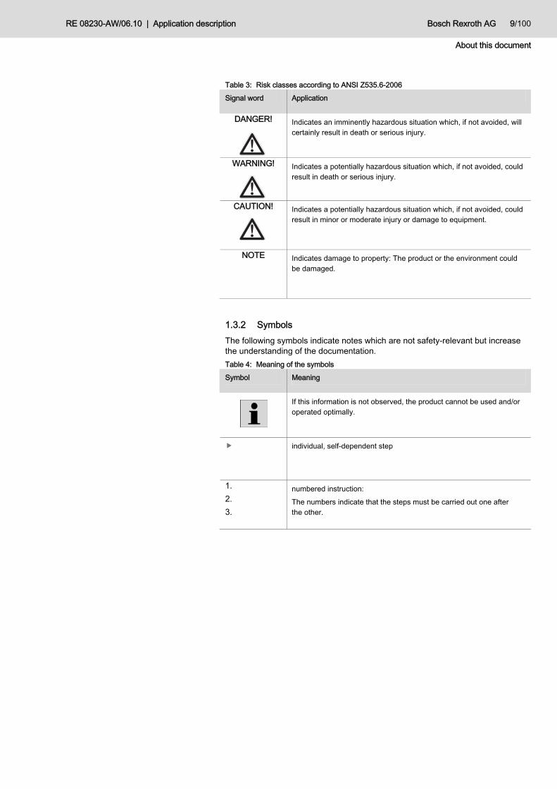
Table 3: Risk classes according to ANSI Z535.6-2006 Signal word Application
DANGER!
Indicates an imminently hazardous situation which, if not avoided, will certainly result in death or serious injury.
WARNING!
Indicates a potentially hazardous situation which, if not avoided, could result in death or serious injury.
CAUTION!
Indicates a potentially hazardous situation which, if not avoided, could result in minor or moderate injury or damage to equipment.
NOTE Indicates damage to property: The product or the environment could be damaged.
1.3.2 Symbols The following symbols indicate notes which are not safety-relevant but increase the understanding of the documentation. Table 4: Meaning of the symbols Symbol Meaning
If this information is not observed, the product cannot be used and/or operated optimally.
individual, self-dependent step
1. 2. 3.
numbered instruction: The numbers indicate that the steps must be carried out one after the other.

10/100 Bosch Rexroth AG Application description | RE 08230-AW/06.10
About this document
1.3.3 Abbreviations used The following abbreviations are used in this documentation: Table 5: Abbreviations Abbreviation Meaning
Dr Drive is ready
AC Alternating Current
DR Drive Release
AU Automatic Mode
ro Ready for operation
CCM Control communication
H High
HW Hardware
KP Pressure control gain factor
L Low
MLD Motion Logic Device
MMC Multimedia Card
M/S Master-Slave
n Speed
OM Online Mode
p Pressure
PC Personal Computer
PM Parameter Mode
PWM Pulse Width Modulation
Q Flow
PLC Programmable Logic Control
SvP Servovariabler Pumpenantrieb (deu) Servo-variable Pump Drive (eng)
TN Reset time of pressure control
TV Derivative time of pressure control

RE 08230-AW/06.10 | Application description Bosch Rexroth AG 11/100
Principal safety instructions
2 Principal safety instructions
2.1 General information on this chapter The product has been manufactured according to the accepted rules of current technology. However, there is still the risk of personal injury and damage to property if you do not observe this chapter and the safety instructions in this documentation.
Read this documentation completely and thoroughly before working with the product.
Keep this documentation in a location where it is accessible to all users at all times.
Always include the required documentation when you pass the product on to third parties.
2.2 Intended use The product is an application software with related parameter set. Application software and parameter set are optimized for the operation of servo-variable pump drives in p/Q control. They may only be used for applications in this area. In this connection, the overall system must satisfy the relevant applicable standards and directives. The application software is not suitable for performing safety-relevant functions. It cannot be guaranteed that the software is free from defects. During its operation, you must therefore take suitable measures in order to avoid and/or minimize the consequences of defects according to the notes in this document. The application software of the standard performance may only be operated in connection with • the control section CSH01.1C and • the firmware FWA-INDRV*-MPH-05VRS-D5-1-NNN-MP,
material number: R911332927 (suitable for technology functions), • and exclusively with the corresponding components of the hardware sets for the
application of servo-variable pump drives.
The application software of the advanced performance may only be operated in connection with • the control section CSH01.3C and • the firmware FWA-INDRV*-MPC-07VRS-D5-1-NNN-MP, material number:
R911332926 (suitable for technology functions) • and exclusively with the corresponding components of the hardware sets for the
application of servo-variable pump drives.
The admissible hardware sets for the standard performance and advanced performance of the application software are shown in Table 6:. The assignment to the relevant software versions is contained in chapter 1.1 "Validity of the instructions".
Standard performance
Advanced performance

12/100 Bosch Rexroth AG Application description | RE 08230-AW/06.10
Principal safety instructions
Table 6: Admissible hardware sets for SvP
Hardware sets divided into power stages Flow
[l/min] Economy Standard Standard 200
High performance
High performance
200
024 -- 24S 24S2 24H 24H2
033 33E 33S 33S2 33H 33H2
048 48E 48S 48S2 48H 48H2
060 60E 60S 60S2 60H 60H2
075 75E 75S 75S2 75H 75H2
100 100E 100S 100S2 100H 100H2
120 120E 120S 120S2 120H 120H2
150 150E 150S 150S2 150H 150H2
190 190E 190S 190S2 -- 190H2
240 -- -- 240S2 -- 240H2
300 -- -- 300S2 -- --
Incorrect parameters Damages to the components of the drive as well as the machine due to
– incorrect command and actual values – incorrect increase times of pressure and speed – incorrect closed-loop speed control – incorrect actuating signal to the electric drive – Incorrect machine function (e.g. pressure too high, pressure too low, negative
rotation of the hydraulic displacer and cavitation)
Check the correct parameter setting directly after entering it into the system.
An application-specific adjustment of the parameters within the scope of the initial commissioning is admissible. The transfer of application software and related parameters by means of MMC to the hardware specified above for the purpose of updating an already existing application software and/ the admissible parameters is permitted. The product is intended for the professional use and not for private use. Intended use includes having read and understood these instructions, especially chapter 2 "Principal safety instructions". The present documentation describes the function of the application software.
NOTE

RE 08230-AW/06.10 | Application description Bosch Rexroth AG 13/100
Principal safety instructions
2.3 Improper use Any use deviating from the intended use is improper and thus not admissible. Bosch Rexroth AG does not assume any liability for damage caused by improper use. The user assumes all risks involved with improper use.
2.4 Qualification of personnel The activities described in this documentation require basic knowledge of electrics and hydraulics as well as knowledge of the appropriate technical terms. In order to ensure safe use, these activities may only be carried out by a corresponding expert or an instructed person under the direction and supervision of an expert. Experts are those who can recognize potential hazards and apply the appropriate safety measures due to their professional training, knowledge and experience, as well as their understanding of the relevant conditions pertaining to the work to be undertaken. An expert must observe the relevant specific professional rules. The following is required as additional qualification: • Knowledge of the wiring of the components: see documentation on the
electrical components (chapter 1.2 "Related documentation") • Knowledge of the commissioning of the application software and adjustment of
the parameters • Basic control engineering knowledge
2.5 General safety instructions • Observe the valid regulations on accident prevention and for environmental
protection. • Observe the safety regulations and provisions of the country where the product
is implemented/used. • Exclusively use Rexroth products in good technical order and condition. • Observe all notes on the product as well as the corresponding documents. • Persons who assemble, operate, disassemble or maintain Rexroth products
must not consume any alcohol, drugs or pharmaceuticals that may affect their ability to respond.
• Only use accessories and spare parts authorized by the manufacturer. • Comply with the technical data and environmental conditions indicated in the
product documentation. • The installation or use of inappropriate products in safety-relevant applications
could result in uncontrolled operating conditions when being used which in turn could cause injuries and/or damages to property. Therefore please only use a product for safety-relevant applications if this use is expressly specified and permitted in the documentation of the product. The application software is not suitable for performing safety-relevant functions.
• Do not commission the product until you can be sure that the end product (for example a machine or system) where the Rexroth product is installed complies with the country-specific provisions, safety regulations and standards of the application.

14/100 Bosch Rexroth AG Application description | RE 08230-AW/06.10
Principal safety instructions
2.6 Product- and technology-related safety instructions The application software SvP cannot be used for the mapping of safety-relevant functions. Suitable measures for the protection of the installation and persons have to be provided by the system.
Error in the application software The following situations may occur on the machine:
– Increased material waste – Increased standstill times – Damage to or destruction of the SvP drive unit – Damage to or destruction of the tool
Check the parameters before commissioning the machine for the first time and ensure that the correct parameter set for the application software is loaded.
Moreover absorb possible consequences by system-internal measures.
Uncontrolled movement of the SvP The system or individual components may be damaged.
Always parameterize the analog inputs correctly and carefully according to the following description.
Limited error detection of hardware defects The error detection of hardware defects can only be performed restrictedly. Further error cases are not supervised (e.g. parasitic coupling, defective fans, cable break with incorrect values in the valid value range, etc.).
– incorrect command and actual values – incorrect increase times of pressure and speed – incorrect closed-loop speed control – incorrect actuating signal to the electric drive – Incorrect machine function (e.g. pressure too high, pressure too low, negative
rotation of the hydraulic displacer and cavitation)
Perform additional supervisions on the system side according to chapters 11.3.1 to 11.3.11.
Moreover absorb possible consequences by system-internal measures.
NOTE
NOTE
NOTE

RE 08230-AW/06.10 | Application description Bosch Rexroth AG 15/100
Principal safety instructions
Incorrect parameterization, missing protection of the parameters against unauthorized access, and missing parameter validation Damages to the components of the drive as well as the machine due to
– incorrect command and actual values – incorrect increase times of pressure and speed – incorrect closed-loop speed control – incorrect actuating signal to the electric drive – Incorrect machine function (e.g. pressure too high, pressure too low, negative
rotation of the hydraulic displacer and cavitation)
Store the set parameters in a back-up copy. Perform the parameterization according to the limits and specifications
contained in this document. Only allow trained and skilled staff to perform parameterization. Check the parameters before commissioning the machine for the first time and
ensure that the correct parameter set for the application software is loaded.
Missing validation of closed-loop control and error monitoring by redundant software or hardware structure Damages to the components of the drive as well as the machine due to
– incorrect command and actual values – incorrect increase times of pressure and speed – incorrect closed-loop speed control – incorrect actuating signal to the electric drive – Incorrect machine function (e.g. pressure too high, pressure too low, negative
rotation of the hydraulic displacer and cavitation)
Perform additional supervisions on the system side. Do not perform any safety-relevant functions with the application software.
NOTE
NOTE

16/100 Bosch Rexroth AG Application description | RE 08230-AW/06.10
Scope of delivery
3 Scope of delivery The scope of delivery includes: • Application software incl. related parameter set on MMC • Firmware depending on the application software on MMC • Application description
The application software and the related parameter set are delivered together with a control section according to the hardware set in Table 6:.
4 Information on this product
4.1 Introduction This document describes the functionality of the application software for the application in a servo-variable pump drive. With this application software, extended functionalities for drive controllers of the "Rexroth IndraDrive" product family are provided. The extended function must be adjusted to the installation in which it will be used (configuration and parameterization).
4.2 Main features Servo-variable pump drives (SvP) largely satisfy the increasing requirements of the market regarding the reduction in noise emission and the increase in energy efficiency. The energy losses occurring with conventional hydraulic power units in partial load operation are reduced by shifting the pressure and displacement control to the electrical drive side. Depending on the required pressure and flow, the speed of the electric motor is selected so that the corresponding output parameters are set. A variable-speed pump drive mainly consists of electric motor, hydraulic pump and a drive controller of the "Rexroth IndraDrive" product family with a specially adjusted application software. In the version with pressure control, you moreover need a pressure transducer. With the project planning program "IndraWorks Ds", the users can adjust the speed-variable pump system to their application by parameterizing the drive controller and the application software. After completed system configuration, the speed-variable pump drive is controlled by thee existing analog and digital inputs and outputs and/or the fieldbus bus system.

RE 08230-AW/06.10 | Application description Bosch Rexroth AG 17/100
Information on this product
Fig. 1: Basic structure of a speed-variable pump system
The drive controllers of the IndraDrive device family consist of a control section and a power section. The control section can be adjusted to the hardware of an application using so-called option modules. The control section also accommodates the main processor which completely controls the drive controller. The "IndraDrive" device family accommodates several classes of control sections which differ in the fitting of the option modules as well as in their individual performance. Due to the higher performance of the main processor and the high variability with regard to the fitting with option modules, only advanced control sections are used. For the application of standard performance, CSH01.1C series control sections are used, and for advanced performance, CSH01.3C series control sections are used. The power section basically contains the power components that are required for controlling the synchronous servo motor. The size of the power section depends on the performance class of the motor. Power sections of type HCS02 or HCS03 are used. The application software is part of the "IndraMotion MLD", the so-called soft PLC or drive-internal PLC. The MLD is part of the firmware of the drive-internal control. The firmware of the drive controller contains all software functions that are necessary for controlling an AC drive motor.
Control section
Power section
Application software

18/100 Bosch Rexroth AG Application description | RE 08230-AW/06.10
Information on this product
The application software for SvP is available in two variants, the so-called standard performance and advanced performance. The difference of these two variants is the velocity with which the speed provision is implemented at the drive. Pressure control is identical for both systems. The standard performance application software is optimized and authorized for the use with the MPH05VRS firmware, while the MPC07VRS firmware must be used for the advanced performance. As already explained above, the selection of the performance level function incorporates the selection of another control section. An overview of the control sections is provided in chapter 4.3 "Component overview". As for the advanced performance, other firmware is used as well, in particular MPC07VRS, the L2 safety modules (start interlock) and the safety system (S2) are supported. Both application solutions, standard and advanced, otherwise have the same scope of functions and are operated equally. The following figure is a graphical presentation of the basic connection of the hardware and software assemblies of the drive controller.
CSH01.1C/CSH01.3C control sectionHCS02 or HCS03 power section
Position,speed and
flow controller
MPH05VRS/MPC07VRS firmware
Devicecontrol
IndraMotion MLD
Sig
nal p
roce
ssin
g
Parameterhandling
Application- softwareOperating
state control
Applicationcontroller
(e.g. p/Q controller)
Diagnosis
Device anderror status
Motor fancontroller
IO m
appi
ngC
omm
unic
atio
nin
terf
ace
pcommand
pactual
ncommand (Qcommand )
Enable
nactual (Qactual)
…
…
Ana
log
and
digi
tal s
igna
ls
AC supply
3~
=
Drive controller
M
Fig. 2: Overview of set-up and structure of the drive controller

RE 08230-AW/06.10 | Application description Bosch Rexroth AG 19/100
Information on this product
4.3 Component overview In this chapter, you will find an overview of the permissible components. The following hardware components are necessary: • Power section Rexroth "IndraDrive C" converter
– HCS02 or HCS03 (standard and advanced performance) – HCS04 (advanced performance)
• Control section – CSH01.1C (standard performance) – CSH01.3C (advanced performance)
• Option modules – ENS (encoder interface) – MA1 (analog I/O extension) – Fieldbus optional (see chapter 7.7 "Input signal via fieldbus bus system")
The following software components are necessary • Drive firmware
– FWA-INDRV*-MPH-05VRS-XX-1-NNN-MP (standard performance) – FWA-INDRV*-MPC-07VRS-XX-1-NNN-MP (advanced performance)
• Application software with parameter set – FWS-MLDTFA-SVP-02VRS-NN-IMM-XXXXX (standard performance) – FWS-MLDTFA-SVP-12VRS-NN-IMM-XXXXX (advanced performance)
Hardware components
Software components

20/100 Bosch Rexroth AG Application description | RE 08230-AW/06.10
Information on this product
4.4 Identification of software and parameter set The software and the related data set can be clearly identified by means of the file names.
Description column
Example: F W S - M L D T F A - S V P - 0 2 V R S - N N - I M M - 5 0 H 21
1 2 3 4 5 6 7 8 910 1 2 3 4 5 6 7 8 9
20 1 2 3 4 5 6 7 8 9
30 1 2 3
1. Firmware connection
1. 1 FWS… = Firmware option
2. Control section assignment
2. 1 MLDTFA… = IndraMotion MLD/ Technology function/ ADVANCED control section
3. Application software
3. 1 SVP… = Servo-variable pump
4. Software release
4. 1 02VRS… = Standard performance4. 2 12VRS… = Advanced performance
5. Language package
5. 1 NN… = Language independent
6. Applications
6. 1 IMM… = Injection molding machine
7. Parameter set hardware assignment
7. 1 150H2 …= Parameter set for hardware set 150 H27. 2 ... Fig. 3: Type key of software and parameter set
If the technology function is integrated in a control section and active, it identifies itself. The version identifier can be read out using parameter P-0-1370 and is stored as decimal value.
Short text column
Example: 0 0 0 2 3 3
1 2 3 4 5 6
= P-0-1370 (decimal)
1. Series identification
1.1 00 …= S00
2. Version identification
2.1 02 …= V02
3. Revision identification
3.1 33 …= R33 Fig. 4: Software identification upon system integration
Identification by means of file designation
Identification by means of parameter entry

RE 08230-AW/06.10 | Application description Bosch Rexroth AG 21/100
Transport and storage
5 Transport and storage
5.1 Transporting software The software is usually supplied together with the firmware on a multimedia card (MMC). Accordingly, the transport provisions for the MMC apply. As this is a software product, there are only the special transport notes listed below: • In case of dispatch by email, the data must always be protected against
unauthorized access by a coding system certified by Bosch (e.g. SECUDE secure mail http://www.secude.com/) or with another adequate coding mechanism (e.g. WinZip http://www.winzip.de/).
• In case of dispatch by means of a Multimedia Card (MMC), appropriate protection against the destruction (e.g. electrostatic discharge) of the data carrier has to be ensured. Further information on the use of an MMC is provided in chapter 1.2 of the instructions for "Firmware for drive controllers ...".
22/100 Bosch Rexroth AG Application description | RE 08230-AW/06.10
Operating instructions for "IndraWorks Ds"
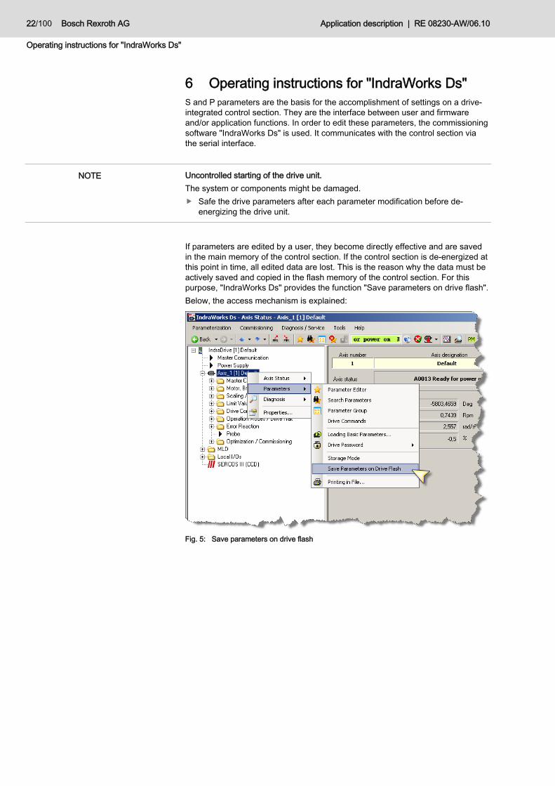
6 Operating instructions for "IndraWorks Ds" S and P parameters are the basis for the accomplishment of settings on a drive-integrated control section. They are the interface between user and firmware and/or application functions. In order to edit these parameters, the commissioning software "IndraWorks Ds" is used. It communicates with the control section via the serial interface.
Uncontrolled starting of the drive unit. The system or components might be damaged.
Safe the drive parameters after each parameter modification before de-energizing the drive unit.
If parameters are edited by a user, they become directly effective and are saved in the main memory of the control section. If the control section is de-energized at this point in time, all edited data are lost. This is the reason why the data must be actively saved and copied in the flash memory of the control section. For this purpose, "IndraWorks Ds" provides the function "Save parameters on drive flash". Below, the access mechanism is explained:
Fig. 5: Save parameters on drive flash
NOTE

RE 08230-AW/06.10 | Application description Bosch Rexroth AG 23/100
Functional description
7 Functional description With the application software for SvP, servo-variable pump drives for hydraulic aggregates in injection molding machines can be realized. They can be operated in pressure/flow control mode (p/Q control) or only in flow control mode (Q control). The application software is adjusted by parameterization. The implemented controller algorithm realizes a pressure and flow control. The pressure and flow command values can be provided electrically as analog command values or via a fieldbus bus system to the drive controller. The actual pressure value is recorded by a pressure transducer at the pump output and supplied to the drive controller. The drive controller controls the speed of the electrical motor so that the pump driven by it displaces exactly the oil quantity corresponding to the flow command value or that is required for providing the command pressure.
M
Customer-specifichydraulic system
Closed-loopspeed control
Applicationcontroller
Pressure commandvalue provision
Flow commandvalue provision
pU
Fig. 6: System structure SvP for controlling pressure and speed
7.1 Modes of operation
7.1.1 General The application software supports five different modes of operation: • Standby operation (ro, Dr) • Parameter mode (PM) • Automatic mode (AU/DR) • Error mode (Error) • Reset mode (Reset)
Parameterizable, further functions can be connected: • Analog input monitoring (see chapter 11.3.7 "FA4A0001 pressure transducer
monitoring") • Automatic offset correction for analog inputs (see chapter 7.8 "Automatic offset
correction")
Field of application

24/100 Bosch Rexroth AG Application description | RE 08230-AW/06.10
Functional description
Fig. 7: State model

RE 08230-AW/06.10 | Application description Bosch Rexroth AG 25/100
Functional description
7.1.2 Standby operation Standby operation is automatically reached after every re-start, if no error was generated or identified during ramp-up. In this mode of operation, the drive controller is fully functional and waits for the power connection for the converter. The display of the drive controller indicates "ro" for "ready for operation" and in addition, notified with signal level "H" via the relay contact X31.2. If the power of the converter is connected by the relay contact X31.9 according to the electrical wiring diagram (Fig. 26:and/or Fig. 27:, chapter 8.3 "SvP controller assembly"), this is immediately notified by the message "Dr" for "Drive ready". For information on the functions in standby operation, please see chapter 7.8 "Automatic offset correction".
7.1.3 Parameter mode The parameter mode is activated by switching the "PM" pushbutton in the menu bar of the commissioning software "IndraWorks Ds".
Fig. 8: "IndraWorks Ds" menu bar
The status of the parameter mode is displayed at the standard operating unit of the control section with the message "PM". Now, the drive parameters can be changed. The parameter mode is usually only used when the drive controller is switched on for the first time in order to adjust the machine data. During parameter mode, the motor is torque-free. The parameter mode can be quit by pressing the "OM" pushbutton in the menu bar. In this case, the system directly switches to "standby mode". It is also possible to select the parameter mode by using the standard operating unit at the drive-integrated control section.
Fig. 9: Standard operating unit
This is how you can select the parameter mode: Keep "Esc" + "Enter" key simultaneously pressed.
As soon as the selection is indicated on the display, you are in the menu structure and can navigate with the arrow keys. The selection request is in menu item 2.11. As soon as the selection request shows ">PM", you must press the "Enter" key and select the parameter mode. You can quit the parameter mode by activating the select request ">ro".

26/100 Bosch Rexroth AG Application description | RE 08230-AW/06.10
Functional description
Via the standard operating part, parameters can only be entered to a limited extent. We therefore recommend using the comfort display or the commissioning software "IndraWorks Ds" for parameter editing. The user can change all system parameters according to the description in chapter 9 "Parameter". The parameter mode can only be selected, if the automatic mode is activated, and the drive has, however, not been started, yet. Should you try anyway, you can neither select the parameter mode, nor an error message is issued. If the user is connected to the control section by means of IndraWorks Ds during this inadmissible event, the following message is displayed.
Fig. 10: Message upon switch-over from OM to PM with available release
7.1.4 Automatic mode By default, the automatic mode is started with signal level "H" at the "Enable Drive" input (X31.3), after the "Automatic offset correction" function (see chapter 7.8 "Automatic offset correction") has been switched according to the settings. The started drive release is notified on the display by means of the message "AU". From this point in time, the torque of the drive is engaged and is subject to the pressure and speed provision according to the system behavior. If the "Enable Drive" release is canceled, the torque of the drive is disengaged and pressure and flow is not controlled anymore. If before, there was pressure in the system, it is discharged system-specifically to the tank via the the hydraulic displacer.
Uncontrolled movement of the hydraulic displacer The system or components might be damaged.
Set the command value provisions for pressure and flow to 0 before taking back the release. This actively reduces the system pressure to the minimum pressure.
NOTE

RE 08230-AW/06.10 | Application description Bosch Rexroth AG 27/100
Functional description
7.1.5 Error mode Depending on the current mode of operation of the control section, numerous errors are monitored. If a faulty condition is recognized that impairs or prevents proper operation, the drive firmware or the application software generates an error message. The error message is shown on the display of the control section and additionally at the "Error message" output (X32.7) with signal level "H". If the error cause has been remedied, deletion of the error memory can be triggered via the "Error reset“ input (X32.8). Without pending errors but with pending signal level "H" at the "Enable Drive" input, drive is enabled immediately. For a more far-reaching error description refer to chapter 11 "Troubleshooting".
7.2 Command management The application software includes the command management function. Several functions are provided which can be initiated from the parameter field (P-0-1300). For standard applications of the SvP for p/Q control, the command management is not necessary, or only necessary if further functionalities are to be used. For the application of advanced functionalities deviating from standard parameterization, please refer to your responsible contact partner at Bosch Rexroth. The command management offers the following functions: • Selection of different user levels
– Login – Logout – Change password – Permanent login – Cancel permanent login
• Recalculate checksum • Select PM • Select OM • Make a reset
There are two parameters for navigating in the command structure Parameter P-0-1300 is used for the input of commands in the form of defined figures. The second parameter P-0-1301 is used to inform the user about the current status. Table 7: Command structure Parameter Description
P-0-1300 Input parameter for commands
P-0-1301 Display parameter for navigation and functional sequence
Commands are entered via parameter P-0-1300 by entering a value and confirming it with "Return". The acceptance of commands can be recognized if the input cell is overwritten with the value "0".
Basic information
Scope of functions
Description

28/100 Bosch Rexroth AG Application description | RE 08230-AW/06.10
Functional description
The display of parameter P-O-1301 must be read according to the following illustration and interpreted accordingly:
Description column
Example: 0 0 0 1 1
1 2 3 4 5
= P-0-1301 (decimal)
1. Path coding
00 ...= main menu
3. User coding
10 …= Development engineer20 …= System engineer30 …= Application engineer40 …= Customer engineer50 …= not logged in
01 ...= user tools
2. Placeholder
0… = Space
11 ...= login12 ...= logout13 ...= change password for customer14 ...= change password for application engineer15 ...= change password for system engineer16 ...= change password for development engineer17 ...= permanent login18 ...= remove permanent login
02 ...= parameter tools21 ...= validate parameter
03 ...= application tools31 ...= activate PM32 ...= activate OM33 ...= reset error
Fig. 11: Display P-0-1301
The main part of the command management is the administration of the user levels. Various additional functionalities deviating from standard parameterization can only be selected by users of a certain user level who are logged in. The following user levels are available: • Not logged in
The "Not logged in" user is not authorized to change P-0-1389 parameters. • Customer
The "Customer" user is authorized to edit the values indicated during commissioning, and to adjust the application software to the conditions of the existing machine, as well as to select PM, OM and Reset. In the condition as supplied, the user is logged in as "Customer".
• Application Engineer The "Application Engineer" user can select and parameterize additional functions. If the use of such functions is required, please refer to your responsible contact partner at Bosch Rexroth.
The illustration of the command structure only shall provide an overview of functions. If you want to use it, please refer to your contact partner at Bosch Rexroth.
User levels

RE 08230-AW/06.10 | Application description Bosch Rexroth AG 29/100
Functional description
Fig. 12: Command menu structure - "main menu"

30/100 Bosch Rexroth AG Application description | RE 08230-AW/06.10
Functional description
Fig. 13: Command menu structure - "user tools"

RE 08230-AW/06.10 | Application description Bosch Rexroth AG 31/100
Functional description
Fig. 14: Command menu structure - "parameter tools"
activate OM
reset error
application toolsP-0-1301 = 030xx
activate PMP-0-1300 = 1 and user is authorised
P-0-1300 = 310xx
is the actual mode OM, it will be switched to PM switched
or 99
P-0-1300 = 320xxP-0-1300 = 2 and user is authorised
is the actual mode PM, it will be switched to OM switched
or 99
P-0-1300 = 330xxP-0-1300 = 3 and user is authorised
exists an error, it will be reseted
switched or 99
Fig. 15: Command menu structure - "application tools"

32/100 Bosch Rexroth AG Application description | RE 08230-AW/06.10
Functional description
7.3 Motor fan control The motor fan control is an optional function which switches the digital output X32.6 via parameter P-0-1419 bit 2 depending on the current motor temperature. The switching signal is provided permanently and can be wired as well, if necessary. The characteristic of the switching function corresponds to that of a two-position controller and/or Schmitt trigger. As motor temperature, the winding temperature of the drive (S-0-0383) is used. The switch-on threshold is specified in parameter P-0-1389[12], and the switch-off threshold is set in parameter P-0-1389[13]. Default values are assigned to both switching thresholds, which can be adjusted, if necessary. The switching function of the motor fan control is low-active. Low-active means: the fan is switched off if signal level "H" is present at the digital output; the fan is switched on, if signal level "L" is present. Table 8: Parameters for fan control Parameter Setting Unit Description
S-0-0383 - °C Current motor winding temperature
P-0-1389[12] 80 °C Switch-on threshold for fan
P-0-1389[13] 60 °C Switch-off threshold for fan
7.4 Double pump selection The double pump selection function allows for the generation of a digital output signal with switching hysteresis depending on pressure threshold. One application sample is the switching of a hydraulic displacer unit in a double pump network against the tank. Table 9: Parameters for double pump selection Parameter Setting Unit Description
P-0-1389[67] 110 bar Switch-off threshold for double pump
P-0-1389[68] 90 bar Switch-on threshold for double pump
Fig. 16: Double pump selection

RE 08230-AW/06.10 | Application description Bosch Rexroth AG 33/100
Functional description
The control signal is calculated depending on the current system pressure (from pressure transducer). If the switch-on threshold is exceeded, a hydraulic displacer is switched against the tank and the digital output is set to "H". If the switch-off threshold is undershot, it is reconnected to the system by setting the digital output to "L". The output signal of the double pump selection is assigned to parameter P-0-1410.3 and can be tapped at X32.9 via the digital output.
7.5 Master-slave operation The master-slave function is used for coupling several SvP systems to form a system network. No additional software or hardware is required. Each SvP system can both be used as master and slave. The use of the SvP application as master means that the application executes a p/Q control according to the system behavior and the command value provisions. If the drive is operated as slave, it will operate in speed control according to the command value provision without consideration of the system pressure. A system network consisting of one master and one or more slaves is used whenever the required hydraulic performance is so high that it cannot be realized by a single SvP application. In the condition as supplied, operation is master by default. In order to switch over from master to slave operation, signal level "H" must be applied to the digital input X31.6 (P-0-1440.13). If the SvP application is operated as slave, only the command value provision is used at the corresponding analog input. The signals at the pressure command value input and at the actual pressure value feedback are not require and are ignored during operation. It is possible to switch dynamically between master and slave function. As setting parameter for the slave function, parameter P-0-1389[35] must be used. With this parameter, the minimum speed for the slave can be specified. It can comply with the complete travel range of the master (e.g. ±3500 rpm), or it can be only positive speed if for example the slave drive is located downstream of the check valve. Table 10: Setting of the slave Parameter Setting Unit Description
P-0-1389[35] 0 rpm Minimum speed for the slave
General
Master-slave switch-over

34/100 Bosch Rexroth AG Application description | RE 08230-AW/06.10
Functional description
Below you can see application examples for a master/slave (M/S) operation:
M M
U p
Actuator
MasterSVP
SlaveSVP
Pressure command value provisionSpeed command value provision
Actual pressure value
Actual speed value master / Speed command value slave
Fig. 17: M/S without check valve
If a check valve is used, both slave and master must actively reduce pressure. For this purpose, P-0-1389[35] must be set to the maximum permissible negative speed.
M M
U p
Actuator
MasterSVP
SlaveSVP
Pressure command value provisionSpeed command value provision
Actual pressure value
Actual speed value master / Speed command value slave
Fig. 18: M/S with check valve
If a check valve is used and pressure is reduced solely by the master, parameter P-0-1389[35] must be set to the value "0" in order to avoid the cavitation of the hydraulic replacer at the slave side.

RE 08230-AW/06.10 | Application description Bosch Rexroth AG 35/100
Functional description
M M
U p
Actuator 1
MasterSVP
Pressure command value provision 1Speed command value provision 1
Actual pressure value 1
Actual speed value master / Speed command value slave
Actuator 2
Master /SlaveSVP
Up Actual pressure value 2
Pressure command value provision 2Speed command value provision 2
Slave mode selection
Fig. 19: Dynamic use of the M/S function
If the SvP application is operated as master and as slave, a command value of pressure and speed must be provided during the complete master mode. The input signal at X31.6 must have the signal level "L". In this state, an independent hydraulic system can be supplied. If switched to slave mode, speed must be provided by the master, and signal level "H" must be applied to X31.6. In this example, due to the check valve, the minimum speed of P-0-1389[35] in slave mode must be "0" in order to avoid the cavitation of the replacer.
Cavitation of the hydraulic replacer The hydraulic replacer might be damaged by cavitation.
Check parameter P-0-1389[35] for correct setting according to the hydraulic connection of the slave axis.
7.6 Leakage compensation The function of leakage compensation offers the alternative of controlling the flow command value. The value is calculated from the speed command value and the system leakage. By activating leakage compensation, the leakage of the hydraulic replacer is compensated. Before carrying out leakage compensation, the leakage of the system must be measured by automatic test processes. This step is usually carried out by the user during commissioning. For the determination of the leakage, a system in "AU/DR" condition is required. All actuators such as the valves of the system must be closed.
General
Leakage determination
NOTE

36/100 Bosch Rexroth AG Application description | RE 08230-AW/06.10
Functional description
Leakage determination is started in the commissioning software "IndraWorks Ds" by assigning signal level "H" to parameter P-O-1440.22. The function is started by a positive clock edge. After activation, the system pressure is automatically increased to a test pressure of 100 bar. As soon as the pressure is reduced to minimum value again, leakage determination is completed and the SvP application follows the command value provided by the command communication. The determined leakage correction value is stored in parameter P-0-1389[112]. The function and application of the leakage correction value and thus the switch-over from speed command value provision to flow command value provision is activated by the digital input X31.7 (P-0-1440.23). If signal level "H" is applied, the system is controlled by the flow command value provision, otherwise by the speed command value provision. Table 11: Parameters for leakage correction Parameter Setting Unit Description
P-0-1389[112] 0 rpm/bar Leakage correction value
P-0-1440 - - Bit 22: Activation of leakage determination Bit 23: Activation of leakage compensation
7.7 Input signal via fieldbus bus system The default parameter set specifies that all command value provisions are provided via the analog and digital interfaces of the drive-integrated control section. If the machine is provided with a fieldbus bus system, it can be used as interface for command value provisions and control signals. For this purpose, the application function is provided with the option to apply all command and actual values selectively to the fieldbus bus system. This requires the use of a corresponding option module for the drive-integrated control section. The following fieldbus option modules for the control section CSH01.1C with firmware MPH05VRS are available: • SE (Sercos 2) • PB (profi bus) • PL (parallel interface) • CO (CANopen/ DeviceNet) • S3 (Sercos III)
The following fieldbus option modules for the control section CSH01.3C with firmware MPH07VRS are available: • SE (Sercos 2) • PB (profi bus) • PL (parallel interface) • CO (CANopen/ DeviceNet) • S3 (Sercos III) • ET (Multi-Ethernet) • CCD (cross communication) - always available
Leakage compensation
General

RE 08230-AW/06.10 | Application description Bosch Rexroth AG 37/100
Functional description
In the application software, it is possible to selectively configure which of the analog or digital signals shall be read in via the fieldbus bus system. For this purpose, two control words are provided, one of which includes the selection of the digital input signals (P-0-1389[0], and the other control word includes the selection of the analog input signals (P-0-1389[5]) (see Table 12:). On signal level "L", "analog/digital" is selected for each signal as a source, on signal level "H", "fieldbus" is selected accordingly. Table 12: Source signal selection Parameter Setting Description
P-0-1389[0] 0 Selection of digital inputs Bit 6: Start of offset compensation Bit 8: Parameter selection 0 Bit 9: Parameter selection 1 Bit 12: Release signal Bit 13: M/S selection Bit 14: Reset Bit 23: Activation of leakage compensation
P-0-1389[5] 0 Selection of analog inputs Bit 0: Speed command value for p/Q control Bit 1: Pressure command value for p/Q control Bit 3: Speed command value for slave mode
With each source signal selection, the source parameter is selected. The mapping for the analog input assignment is already included in the default parameter set. If a fieldbus bus system is used, the source parameters must be mapped with the commissioning software "IndraWorks Ds" according to the use of an option card extension. Table 13: shows the assignment of the source signals to the parameters: Table 13: Signal assignment Parameter Parameter for source
selection "analog/digital" Parameter for source selection "Fieldbus"
Start of offset compensation
P-0-1440.6 P-0-1441.6
Parameter selection 0 P-0-1440.8 P-0-1441.8
Parameter selection 1 P-0-1440.9 P-0-1441.9
Release signal P-0-1440.12 P-0-1441.12
Slave selection P-0-1440.13 P-0-1441.13
Reset P-0-1440.14 P-0-1441.14
Activation of leakage compensation
P-0-1440.23 P-0-1441.23
Speed command value for p/Q control
P-0-0229 P-0-1392
Pressure command value for p/Q control
P-0-0228 P-0-1393
Speed command value for slave mode
P-0-0229 P-0-1395
Source signal selection
38/100 Bosch Rexroth AG Application description | RE 08230-AW/06.10
Functional description
If using a fieldbus bus system, please note that you only use the parameters indicated in this manual for the control of the SvP system. In case of drive control using fieldbus control words, malfunctions of the commissioning software might occur, or the application software cannot be executed anymore. For questions with regard to project planning, please refer to your contact partner at Bosch Rexroth.
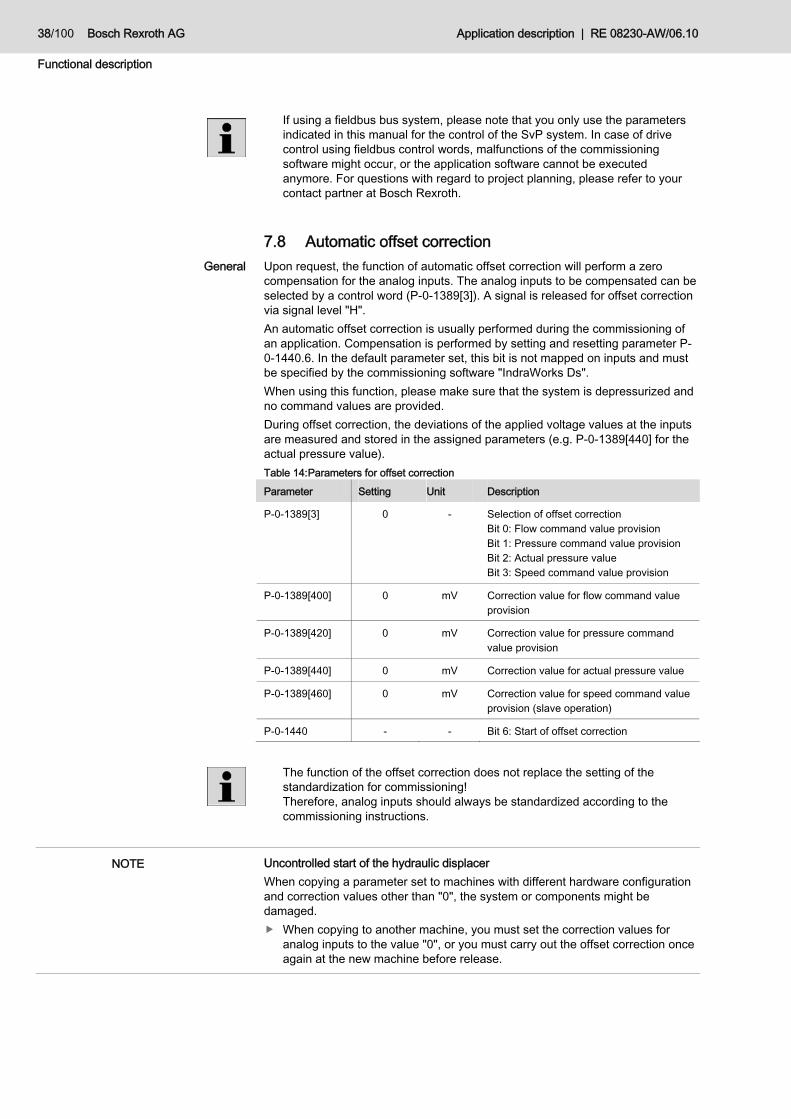
7.8 Automatic offset correction Upon request, the function of automatic offset correction will perform a zero compensation for the analog inputs. The analog inputs to be compensated can be selected by a control word (P-0-1389[3]). A signal is released for offset correction via signal level "H". An automatic offset correction is usually performed during the commissioning of an application. Compensation is performed by setting and resetting parameter P-0-1440.6. In the default parameter set, this bit is not mapped on inputs and must be specified by the commissioning software "IndraWorks Ds". When using this function, please make sure that the system is depressurized and no command values are provided. During offset correction, the deviations of the applied voltage values at the inputs are measured and stored in the assigned parameters (e.g. P-0-1389[440] for the actual pressure value). Table 14: Parameters for offset correction Parameter Setting Unit Description
P-0-1389[3] 0 - Selection of offset correction Bit 0: Flow command value provision Bit 1: Pressure command value provision Bit 2: Actual pressure value Bit 3: Speed command value provision
P-0-1389[400] 0 mV Correction value for flow command value provision
P-0-1389[420] 0 mV Correction value for pressure command value provision
P-0-1389[440] 0 mV Correction value for actual pressure value
P-0-1389[460] 0 mV Correction value for speed command value provision (slave operation)
P-0-1440 - - Bit 6: Start of offset correction
The function of the offset correction does not replace the setting of the standardization for commissioning! Therefore, analog inputs should always be standardized according to the commissioning instructions.
Uncontrolled start of the hydraulic displacer When copying a parameter set to machines with different hardware configuration and correction values other than "0", the system or components might be damaged.
When copying to another machine, you must set the correction values for analog inputs to the value "0", or you must carry out the offset correction once again at the new machine before release.
General
NOTE

RE 08230-AW/06.10 | Application description Bosch Rexroth AG 39/100
Functional description
7.9 Parameter adjustment
7.9.1 Adjustment to system rigidity By means of data set selection, it is possible to select between different data sets. This allows for the simple optimization with regard to the system rigidity. The parameter selection offers the option to store individual settings at control parameters and to select them via digital inputs. The four parameter sets are assigned by default with an assignment which is independent of the system volume. Thus, it is possible to quickly select between different parameter sets for a defined machine size and/or axis on a machine without much application efforts. If individual parameterizations are required, the parameter sets can be applied individual by means of the commissioning software "IndraWorks Ds" and a PC. A possible application is the storage of optimized parameters for different machine sizes and/or axes. This means that data sets for up to four machine sizes or axes are stored in one parameter set. The adjustment to machine size and/or axis must be accomplished by selecting the digital inputs in accordance with each data set. In a default parameter set, the parameters of different machine sizes and/or axes are assigned as follows, whereas the system volumes must be regarded as guidelines: • Data set 0: System volume < 1 l • Data set 1: 1 l <= system volume < 3 l • Data set 2: 3 l <= Systemvolumen < 6 l • Data set 3: 6 l < system volume
The parameter adjustment function is responsible for the management of the pressure control parameters. For this purpose, there are four different pressure control data sets between which you can change to runtime. Each data set reflects the optimized parameters for each hydraulic system volume. Via the two digital inputs at the parameters P-0-1440.8 and P-0-1440.9, you can switch between the four data sets: • "Setting parameter set – PS0" at X31.4 • "Setting parameter set – PS1" at X31.5
Table 15: Data set selection
PS1 PS0 Selected data set [index]
L L 0
L H 1
H L 2
H H 3
General
Target description
Functional description
Assignment of the data set selection for digital input encoding

40/100 Bosch Rexroth AG Application description | RE 08230-AW/06.10
Functional description
7.9.2 Adjustment to system pressure Each data set consists of parameters for gain (KP), for reset time (TN), for derivative time (TV), as well as two adaptation factors. An optimization overview is provided in chapter 7.10 "Application controller".
Table 16: Control parameters for pressure control
Parameter Setting Unit Description Data set
P-0-1389[204] 1000 rpm/(1000*bar*ms) Reset time TN [0]
P-0-1389[205] 1000 rpm/(1000*bar*ms) Reset time TN [1]
P-0-1389[206] 1000 rpm/(1000*bar*ms) Reset time TN [2]
P-0-1389[207] 1000 rpm/(1000*bar*ms) Nachstellzeit TN [3]
P-0-1389[208] 600000 rpm*ms/(1000*bar) Derivative time TV [0]
P-0-1389[209] 0 rpm*ms/(1000*bar) Derivative time TV [1]
P-0-1389[210] 0 rpm*ms/(1000*bar) Derivative time TV [2]
P-0-1389[211] 0 rpm*ms/(1000*bar) Derivative time TV [3]
P-0-1389[214] 40000 rpm/1000 bar Gain KP
P-0-1389[217] 37000 µs Adaptation factor 1
P-0-1389[218] 25000 µs Adaptation factor 2
0
P-0-1389[229] 1100 rpm/(1000*bar*ms) Reset time TN [0]
P-0-1389[230] 1000 rpm/(1000*bar*ms) Reset time TN [1]
P-0-1389[231] 1000 rpm/(1000*bar*ms) Reset time TN [2]
P-0-1389[232] 1100 rpm/(1000*bar*ms) Reset time TN [3]
P-0-1389[233] 200000 rpm*ms/(1000*bar) Derivative time TV [0]
P-0-1389[234] 0 rpm*ms/(1000*bar) Derivative time TV [1]
P-0-1389[235] 0 rpm*ms/(1000*bar) Derivative time TV [2]
P-0-1389[236] 0 rpm*ms/(1000*bar) Derivative time TV [3]
P-0-1389[239] 50000 rpm/1000*bar Gain KP
P-0-1389[242] 55000 µs Adaptation factor 1
P-0-1389[243] 25000 µs Adaptation factor 2
1
P-0-1389[254] 800 rpm/(1000*bar*ms) Reset time TN [0]
P-0-1389[255] 800 rpm/(1000*bar*ms) Reset time TN [1]
P-0-1389[256] 800 rpm/(1000*bar*ms) Reset time TN [2]
P-0-1389[257] 800 rpm/(1000*bar*ms) Reset time TN [3]
P-0-1389[258] 200000 rpm*ms/(1000*bar) Derivative time TV [0]
P-0-1389[259] 0 rpm*ms/(1000*bar) Derivative time TV [1]
P-0-1389[260] 0 rpm*ms/(1000*bar) Derivative time TV [2]
P-0-1389[261] 0 rpm*ms/(1000*bar) Derivative time TV [3]
P-0-1389[264] 60000 rpm/1000*bar Gain KP
P-0-1389[267] 75000 µs Adaptation factor 1
2
Pressure-dependent parameter selection within one data set

RE 08230-AW/06.10 | Application description Bosch Rexroth AG 41/100
Functional description
Parameter Setting Unit Description Data set
P-0-1389[268] 25000 µs Adaptation factor 2
P-0-1389[279] 1000 rpm/(1000*bar*ms) Reset time TN [0]
P-0-1389[280] 1000 rpm/(1000*bar*ms) Reset time TN [1]
P-0-1389[281] 1000 rpm/(1000*bar*ms) Reset time TN [2]
P-0-1389[282] 1000 rpm/(1000*bar*ms) Reset time TN [3]
P-0-1389[283] 200000 rpm*ms/(1000*bar) Derivative time TV [0]
P-0-1389[284] 0 rpm*ms/(1000*bar) Derivative time TV [1]
P-0-1389[285] 0 rpm*ms/(1000*bar) Derivative time TV [2]
P-0-1389[286] 0 rpm*ms/(1000*bar) Derivative time TV [3]
P-0-1389[289] 60000 rpm/1000*bar Gain KP
P-0-1389[292] 80000 µs Adaptation factor 1
P-0-1389[293] 25000 µs Adaptation factor 2
3
7.10 Application controller The application controller has the basic function of a PID controller plus application-specific functions. These functions allow for the optimal adjustment to a specific target system. An exemplary optimization of the application controller is only carried out for data set "0". Data sets 1...3 can be optimized accordingly, if required.
7.10.1 Gain optimization In order to optimize the gain factor KP, you must start with the default parameters and set the value for all acting TN values to "0". Then you must reduce the KP value by approx. 50% and continuously increase it in steps of 2000 until the desired system behavior is achieved. The target is to maintain the lowest possible remaining control deviation without overshooting or instabilities. If overshooting or instabilities are recognized, the entered value must be reduced (see Fig. 20:).
General

42/100 Bosch Rexroth AG Application description | RE 08230-AW/06.10
Functional description
t
p
pactual
pcommand
KP
Fig. 20: Gain optimization
Table 17: Parameterization of the dynamic gain factor KP Parameter Setting Unit Description Data set
P-0-1389[214] 40000 rpm/1000*bar Gain KP 0
P-0-1389[239] 50000 rpm/1000*bar Gain KP 1
P-0-1389[264] 60000 rpm/1000*bar Gain KP 2
P-0-1389[289] 60000 rpm/1000*bar Gain KP 3
7.10.2 Reset time optimization After gain optimization, reset time TN can be adjusted, if required. For the optimization of the reset time, you have to start with default parameters. If the rise time to a pressure command value with a pressure command value step is too slow, the TN[0] value has to be increased in order to achieve a steeper pressure increase. If the pressure overshooting is over 20 bar, it can be reduced by increasing TN[3]. In order to reduce instabilities during the leveling off process and to achieve a fast rise time, nevertheless, both values TN[1] and TN[2] must be optimized according to Fig. 21:.

RE 08230-AW/06.10 | Application description Bosch Rexroth AG 43/100
Functional description
t
p
TN [0]
pactual
pcommand
TN [2]
TN [1]
TN [3]
Fig. 21: Reset time optimization
Table 18: Parameterization of the reset time TV Parameter Setting Unit Description Data set
P-0-1389[204] 1000 rpm/(1000*bar*ms) TN [0]
P-0-1389[205] 1000 rpm/(1000*bar*ms) TN [1]
P-0-1389[206] 1000 rpm/(1000*bar*ms) TN [2]
P-0-1389[207] 1000 rpm/(1000*bar*ms) TN [3]
0
P-0-1389[229] 1100 rpm/(1000*bar*ms) TN [0]
P-0-1389[230] 1000 rpm/(1000*bar*ms) TN [1]
P-0-1389[231] 1000 rpm/(1000*bar*ms) TN [2]
P-0-1389[232] 1100 rpm/(1000*bar*ms) TN [3]
1
P-0-1389[254] 800 rpm/(1000*bar*ms) TN [0]
P-0-1389[255] 800 rpm/(1000*bar*ms) TN [1]
P-0-1389[256] 800 rpm/(1000*bar*ms) TN [2]
P-0-1389[257] 800 rpm/(1000*bar*ms) TN [3]
2
P-0-1389[279] 1000 rpm/(1000*bar*ms) TN [0]
P-0-1389[280] 1000 rpm/(1000*bar*ms) TN [1]
P-0-1389[281] 1000 rpm/(1000*bar*ms) TN [2]
P-0-1389[282] 1000 rpm/(1000*bar*ms) TN [3]
3

44/100 Bosch Rexroth AG Application description | RE 08230-AW/06.10
Functional description
7.10.3 Derivative time optimization The derivative time TV is already optimized in the default parameter set and does usually not need to be adjusted. The rise behavior of the system can be optimized with the derivative time TV[0]: • Increasing TV[0] slows down the rise behavior • Reducing TV[0] accelerates the rise behavior
t
p
pactual
pcommand
TV[0]
Fig. 22: Derivative time optimization
Table 19: Parameterization of the derivative time TV Parameter Setting Unit Description Data set
P-0-1389[208] 600000 rpm*ms/(1000*bar) TV [0] 0
P-0-1389[233] 200000 rpm*ms/(1000*bar) TV [0] 1
P-0-1389[258] 200000 rpm*ms/(1000*bar) TV [0] 2
P-0-1389[283] 200000 rpm*ms/(1000*bar) TV [0] 3
7.10.4 Adaptation factor optimization If despite an optimal controller setting, the overshooting during upward steps cannot be adequately suppressed, it can be reduced or even completely avoided by increasing adaptation factor 1. If despite an optimized controller, undershooting occurs during downward steps, this undershooting can be suppressed with adaptation factor 2. Please note that the response time of the system is, however, delayed due to these measures. A compromise between the application of this function and controller optimization has to be made.

RE 08230-AW/06.10 | Application description Bosch Rexroth AG 45/100
Functional description
t
p
pcommand
Adaptation factor 1Adaptation factor 2
pactualS
Fig. 23: Adaptation factor optimization
Table 20: Parameterization of the adaptation factors Parameter Setting Unit Description Data set
P-0-1389[217] 37000 µs Adaptation factor 1
P-0-1389[218] 25000 µs Adaptation factor 2
0
P-0-1389[242] 55000 µs Adaptation factor 1
P-0-1389[243] 25000 µs Adaptation factor 2
1
P-0-1389[267] 75000 µs Adaptation factor 1
P-0-1389[268] 25000 µs Adaptation factor 2
2
P-0-1389[292] 80000 µs Adaptation factor 1
P-0-1389[293] 25000 µs Adaptation factor 2
3
7.11 Inputs / outputs
7.11.1 Standardization of the analog inputs and outputs
In order to ensure the correct function of the application software, the input and output signals must be adjusted to the physical voltage ranges of the hardware connected to the inputs and outputs. For this purpose, the standardization function is available for every input and output. Standardization consists in each case of three values: • Measuring range: output or display range of the measurement • Voltage range: Value range of the voltage according to the measuring range

46/100 Bosch Rexroth AG Application description | RE 08230-AW/06.10
Functional description
• Voltage offset: Additive deviation of the voltage range from the measuring range
Table 21: Standardization parameters
Parameter Setting Unit Description Assignment
P-0-1389[402] 3000000 rpm/1000 Voltage range
P-0-1389[404] 10000 mV Measuring range
P-0-1389[406] 0 mV Voltage offset
Speed command value (input)
P-0-1389[422] 400000 mbar Voltage range
P-0-1389[424] 10000 mV Measuring range
P-0-1389[426] 0 mV Voltage offset
Pressure command value (input)
P-0-1389[442] 400000 mbar Voltage range
P-0-1389[444] 10000 mV Measuring range
P-0-1389[446] 0 mV Voltage offset
Actual pressure value (input)
P-0-1389[542] 400000 mbar Voltage range
P-0-1389[544] 10000 mV Measuring range
P-0-1389[546] 0 mV Voltage offset
Actual pressure value (output)
P-0-1389[562] 3000000 rpm/1000 Voltage range
P-0-1389[564] 10000 mV Measuring range
P-0-1389[566] 0 mV Voltage offset
Actual speed value (output)
7.11.2 Dead zone function The dead zone function delays the input data by a parameterizable value (dead time). The module can be connected for the "Speed command value" and "Pressure command value" analog inputs. The function is activated via the control word P-0-1389[19]. The dead zone function delays a positive step of the command value provision as soon as it exceeds a specified threshold value. This threshold value can be individually determined for every analog input. These functions are useful if they are not assumed for command value generation by a superior control.
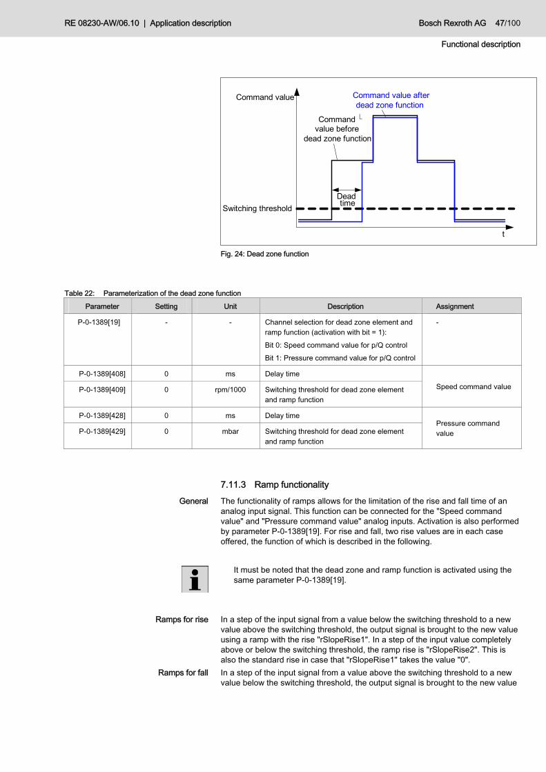
RE 08230-AW/06.10 | Application description Bosch Rexroth AG 47/100
Functional description
Deadtime
Command value afterdead zone function
Command value
Switching threshold
�Command value before
dead zone function
t
Fig. 24: Dead zone function
Table 22: Parameterization of the dead zone function
Parameter Setting Unit Description Assignment
P-0-1389[19] - - Channel selection for dead zone element and ramp function (activation with bit = 1): Bit 0: Speed command value for p/Q control Bit 1: Pressure command value for p/Q control
-
P-0-1389[408] 0 ms Delay time
P-0-1389[409] 0 rpm/1000 Switching threshold for dead zone element and ramp function
Speed command value
P-0-1389[428] 0 ms Delay time
P-0-1389[429] 0 mbar Switching threshold for dead zone element and ramp function
Pressure command value
7.11.3 Ramp functionality The functionality of ramps allows for the limitation of the rise and fall time of an analog input signal. This function can be connected for the "Speed command value" and "Pressure command value" analog inputs. Activation is also performed by parameter P-0-1389[19]. For rise and fall, two rise values are in each case offered, the function of which is described in the following.
It must be noted that the dead zone and ramp function is activated using the same parameter P-0-1389[19].
In a step of the input signal from a value below the switching threshold to a new value above the switching threshold, the output signal is brought to the new value using a ramp with the rise "rSlopeRise1". In a step of the input value completely above or below the switching threshold, the ramp rise is "rSlopeRise2". This is also the standard rise in case that "rSlopeRise1" takes the value "0". In a step of the input signal from a value above the switching threshold to a new value below the switching threshold, the output signal is brought to the new value
General
Ramps for rise
Ramps for fall

48/100 Bosch Rexroth AG Application description | RE 08230-AW/06.10
Functional description
using a ramp with the rise "rSlopeFall1". In a step of the input value completely above or below the switching threshold, the ramp rise is "rSlopeFall2". This is also the standard rise in case that "rSlopeFall1" takes the value "0". The time basis of the rise is 1 ms.
Command valuesafter ramp function
Command value
Switching threshold
1s
rSlopeRise 2
1s
rSlopeRise1
1s
rSlopeFall 2
1s
rSlopeFall 1
Command valuesbefore ramp function
t
Fig. 25: Ramp function
Table 23: Parameterization of the ramp function
Parameter Setting Unit Description Assignment
P-0-1389[19] - - Channel selection for dead zone element and ramp function (activation with bit = 1): Bit 0: Speed command value for p/Q control Bit 1: Pressure command value for p/Q control
-
P-0-1389[409] 0 rpm/1000 Switching threshold for dead zone element and ramp function
P-0-1389[410] 0 rpm/s Rise (rSlopeRise1) after exceeding the switching threshold in pos. direction
P-0-1389[411] 0 rpm/s Rise (rSlopeRise2) unless rSlopeRise1
P-0-1389[412] 0 rpm/s Fall (rSlopeFall1) after exceeding the switching threshold in neg. direction
P-0-1389[413] 0 rpm/s Fall (rSlopeFall2) unless rSlopeFall1
Speed command value
P-0-1389[429] 0 mbar Switching threshold of dead zone element and ramp function
P-0-1389[430] 0 bar/s Rise (rSlopeRise1) after exceeding the switching threshold in pos. direction
P-0-1389[431] 0 bar/s Rise (rSlopeRise2) unless rSlopeRise1
P-0-1389[432] 0 bar/s Fall (rSlopeFall1) after exceeding the switching threshold in neg. direction
P-0-1389[433] 0 bar/s Fall (rSlopeFall2) unless rSlopeFall1
Pressure command value

RE 08230-AW/06.10 | Application description Bosch Rexroth AG 49/100
Functional description
7.11.4 Minimum command values
It is possible for the analog inputs of the command value provision "Speed command value" and "Pressure command value" to define minimum values. The minimum admissible pressure is provided via parameter P-0-1389[14] and the minimum speed is provided in parameter P-0-1389[18]. The minimum permissible pressure limits the pressure command value provision downwards. The minimum speed limits the speed provision downwards if the actual pressure value falls below the minimum pressure. The default values are optimized for the application of the injection molding machine. If necessary, they can be adjusted to system-dependent features. Table 24: Parameterization of the minimum command values Parameter Setting Unit Description
P-0-1389[14] 5 bar Minimum admissible system pressure
P-0-1389[18] 200 rpm Minimum speed in case the minimum system pressure is not achieved

50/100 Bosch Rexroth AG Application description | RE 08230-AW/06.10
Installation
8 Installation
8.1 Required tools For changing the application and for the initial commissioning by means of the PC, you need the following tools: • Standard performance: PC with serial interface (D-SUB, 9-pole) • Advanced performance: PC with Ethernet interface (RJ45) • PC with "IndraWorks Ds" commissioning software
Please make sure that the parameters of standard performance applications are changed via the serial interface of the control section, and the advanced performance applications are parameterized via the engineering Ethernet interface at the drive-integrated control section.
For quick commissioning, a register card will be embedded in the project structure of "IndraWorks Ds" by means of which the application-specific parameters can be entered quickly and in a clearly laid out manner. In order to query the current status of this input assistance, please contact your responsible account manager at Bosch Rexroth. Alternatively, a commissioning without PC is possible. For this purpose, the comfort operating unit VCP01.2BWA-TS-NN-FW (material number: R911316971) must be used. By means of this operating unit, all parameters can be changed according to the commissioning instructions. In future, commissioning by means of a standard operating unit will be possible, which is a cheaper alternative. In order to query the current status of this input assistance, please contact your responsible account manager at Bosch Rexroth.
8.2 Required accessories For initial commissioning, an MMC with application software for SvP and the related firmware is required. Each SvP set has its own MMC with specific settings. If you have several machines of one size with an identical SvP set, you only need to order one MMC with the required information. If you have a set without MMC with related software, and if you need the application software, please refer to your contact partner at Bosch Rexroth. In order to transfer the commissioning software with stored parameters to another control section, the following accessories are required that are not included in the delivery contents and that you can order from Bosch Rexroth:
Commissioning with PC
Commissioning without PC
MMC with application software
MMC without application software

RE 08230-AW/06.10 | Application description Bosch Rexroth AG 51/100
Installation
Table 25: Necessary accessories for parameter transfer Component Material number
PFM02.1-016-NW (MMC without firmware)
R911298785
In order to change the application parameters of the software and to accomplish the initial commissioning, the following accessories are required that are not included in the delivery contents and that you can order from Bosch Rexroth: Table 26: Necessary accessories for parameter editing at CSH01.C Component Material number
IKB0041 (interface cable)
R911296710
Table 27: Necessary accessories for parameter editing at CSH01.3C Component Material number
Ethernet 10/100 Mbit/s RJ45 (Interface cable)
-
8.3 SvP controller assembly For the assembly of a SvP system, the corresponding documentation of the hardware components has to be observed (see chapter 1.2 "Related documentation"). The pinout of the drive controller reflects a typical allocation according to the application-specific requirements of an SvP. In other applications, the I/O allocation may within the scope of the configuration possibilities of the technology function deviate from the illustration below.
Interface cable

52/100 Bosch Rexroth AG Application description | RE 08230-AW/06.10
Installation
Fig. 26: Input/output allocation at the drive controller (standard performance)

RE 08230-AW/06.10 | Application description Bosch Rexroth AG 53/100
Installation
Fig. 27: Input/output allocation at the drive controller (advanced performance)

54/100 Bosch Rexroth AG Application description | RE 08230-AW/06.10
Installation
8.3.1 Pressure transducer connection
The pressure control loop is closed by means of the pressure transducer. It is recommended to use pressure transducer HM17. If a different pressure transducer is used, you must first check its compatibility. For pressure measurement, a pressure transducer with a voltage output within the range from 0 to 10 V must be used. We recommend a voltage offset for actual value output in order to be able to use the Cable break detection function (chapter 11.3.1 "FA450001 drive controller error"). The pressure transducer is connected to the plug terminals X32.4 and X32.5 of the control section. The signal line is to be connected to X32.4, the reference signal to X32.5. The measuring lines are to be shielded together and the shield has to be connected to X32.3.
Fig. 28: Connection of the pressure transducer
8.3.2 ENS encoder connection The encoder analysis ENS is connected at option port 1 of the control section. It analyzes signals from the encoder system of the series "IndraDyn S" motors (MSK motors).
Connect the encoder of the motors with the encoder analysis ENS via an encoder cable.
8.3.3 Analog input and output connection
The connection of the analog input and output signals except for the pressure signal of the pressure transducer (see chapter 8.3.1 "Pressure transducer connection") is provided by a MA1 card. The MA1 card is an analog extension module and is integrated in the control section CSH01.1C at option port 3 or in the control section CSH01.3C at option port 2.

RE 08230-AW/06.10 | Application description Bosch Rexroth AG 55/100
Installation
The interface of the MA1 card is a 15-pole D-Sub socket. The MA1 card allows for the read-in of two voltage signals in the range from 0 V..10 V as well as for the output of two voltage signals in the range from -10 V..+ 10 V. Analog signals and reference signals are to be shielded and wired together. The shield must be applied to the housing of the converter. Fig. 29: shows the allocation of the analog input pins of the MA1 card.
Fig. 29: Option module MA1
Table 28: Option module MA1 allocation PIN designation Description Assignment
8 Housing Housing earthing -
15 GNDA Reference potential
7 GND100 Shield connection
14 +AA2 Signal line
Analog output 2 (current motor speed)
6 GNDA Reference potential
13 GND100 Shield connection
5 +AA1 Reference potential
Analog output 1 (current actual pressure value)
12 GNDA not connected
4 +AE2 Signal line
11 -AE2 Reference potential
3 GND100 Shield connection
Analog input 2 (speed command value)
10 GNDA not connected
2 +AE1 Signal line
9 -AE1 Reference potential
1 GND100 Shield connection
Analog input 1 (pressure command value)
Assignment of the functions of the analog I/Os to the MA1 card

56/100 Bosch Rexroth AG Application description | RE 08230-AW/06.10
Parameter
9 Parameter This chapter contains the parameter description of the application software SvP. It serves for the specification and adjustment of the system components and the activation of functionalities. For system parameterization, the commissioning software "IndraWorks Ds" and the comfort operating unit are provided.
Table 29: System parameters
Para-meter
Index [x] Designation Unit Value range Default value Description
S-0-0091 - Bipolar speed limit
rpm 0 to 214748.3647
3500 Value for the maximum permissible speed command value of the motor depending on the application and independent of the direction of rotation.
S-0-0100 - Speed controller proportional gain
Nm/ (rad/s)
0 to 214783.647
2
S-0-0101 - Speed controller reset time
ms 0 to 6553.5 40
The speed controller calculates the torque/force command value ("P-0-0049") from the difference of the speed command value and the actual speed value (=S-0-0347, speed control deviation).
P-0-0228 - Pressure command value provision, analog
V 0 to 10 0 Analog input for the pressure command value provision in master operation
P-0-0229 - Speed command value provision, analog
V 0 to 10 0 Analog input for the speed command value in master and slave operation
0 - - P-0-0861
1 - - P-0-1440
2 - - P-0-1440
3 - - P-0-1440
4 - - P-0-1440
5 - - P-0-1440
6 - - S-0-0000
7 - - S-0-0000
8 - - P-0-1419
9 - - P-0-1410
10 - - P-0-1440
P-0-0300
11
Digital l/O, assignment list
- - P-0-1410
With parameter "P00300", the drive signals are allocated to the digital inputs/outputs of the control section by configuring the related IDN number in the list parameter.
0 - - 9
1 - - 12
2 - - 8
P-0-0301
3
Digital l/O, bit numbers
- - 9
In "P00301, digital I/O, bit numbers", the desired bit number which shall be assigned to the digital input/output is indicated for
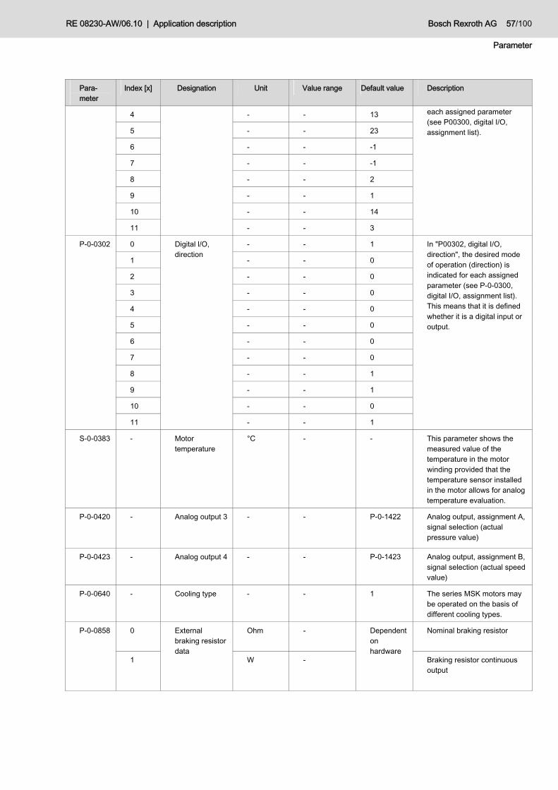
RE 08230-AW/06.10 | Application description Bosch Rexroth AG 57/100
Parameter
Para-meter
Index [x] Designation Unit Value range Default value Description
4 - - 13
5 - - 23
6 - - -1
7 - - -1
8 - - 2
9 - - 1
10 - - 14
11 - - 3
each assigned parameter (see P00300, digital I/O, assignment list).
0 - - 1
1 - - 0
2 - - 0
3 - - 0
4 - - 0
5 - - 0
6 - - 0
7 - - 0
8 - - 1
9 - - 1
10 - - 0
P-0-0302
11
Digital l/O, direction
- - 1
In "P00302, digital I/O, direction", the desired mode of operation (direction) is indicated for each assigned parameter (see P-0-0300, digital I/O, assignment list). This means that it is defined whether it is a digital input or output.
S-0-0383 - Motor temperature
°C - - This parameter shows the measured value of the temperature in the motor winding provided that the temperature sensor installed in the motor allows for analog temperature evaluation.
P-0-0420 - Analog output 3 - - P-0-1422 Analog output, assignment A, signal selection (actual pressure value)
P-0-0423 - Analog output 4 - - P-0-1423 Analog output, assignment B, signal selection (actual speed value)
P-0-0640 - Cooling type - - 1 The series MSK motors may be operated on the basis of different cooling types.
0 Ohm - Nominal braking resistor
P-0-0858
1
External braking resistor data
W -
Dependent on hardware
Braking resistor continuous output

58/100 Bosch Rexroth AG Application description | RE 08230-AW/06.10
Parameter
Para-meter
Index [x] Designation Unit Value range Default value Description
2 kWs - Max. refeed energy
3 V - Braking resistor switch-on threshold
P-0-0860 - Converter configuration
- - Dependent on hardware
Bit 8: Efficient braking resistor (internal/external) 0 = internal braking resistor activated at HCS02 (default) Device without (or with deactivated) braking transistor at HCS03/04. 1 = external braking resistor active (HCS02/ 03 /04) and internal braking resistor deactivated if an external braking resistor is connected (HCS02).
P-0-1203 - Gradient ramp rad/s2 0 to 2147483.647
8000 Maximum speed acceleration
P-0-1213 - Delay ramp rad/s2 0 to 2147483.647
25000 Maximum speed delay
P-0-1300 - - - - 0 Input parameter for commands
P-0-1301 - - - - 40 Display parameter for navigation and functional sequence
P-0-1370 - Software version
- - - Software version of the SvP application software. SxxVxxRxx
P-0-1371 - Incorrect parameter input
- - 0 One list element in P-0-1389[x] is outside the permissible limits. The incorrect list element x is indicated here.
P-0-1372 - Error message - - 0 Coded error display FAxxxxxx

RE 08230-AW/06.10 | Application description Bosch Rexroth AG 59/100
Parameter
Para-meter
Index [x] Designation Unit Value range Default value Description
0 Control word 1 - -2147483648 to 2147483647
0 Source selection for digital signals between digital inputs P-0-1440( Bit = 0) or fieldbus P-0-1441 (Bit = 1) Bit 6: Start of offset compensation Bit 8: Parameter selection 0 Bit 9: Parameter selection 1 Bit 12: Release signal Bit 13: M/S selection Bit 14: Reset Bit 23: Activation of leakage compensation
2 Input value check after system start
- -2147483648 to 2147483647
0 Channel selection for the selection of the analog inputs to be checked (selection with bit = 1) Bit 2: Actual pressure value of pressure transducer
3 Offset correction
- -2147483648 to 2147483647
0 Channel selection for the selection of the input channels to be compensated (selection with bit = 1) Bit 0: Flow command value provision Bit 1: Pressure command value provision Bit 2: Actual pressure value Bit 3: Speed command value provision
5 Control word 2 - -2147483648 to 2147483647
0 Source selection for analog signals between analog input (bit = 0) or fieldbus (bit = 1) Bit 0: Speed command value for p/Q control Bit 1: Pressure command value for p/Q control Bit 3: Speed command value in slave operation
12 Fan on °C 0 to 160 80 Switch-on threshold for fan control
13 Fan off °C 0 to 160 60 Switch-off threshold for fan control
14 Minimum pressure
bar 0 to 315 5 Minimum admissible system pressure
16 Negative speed limit
rpm 0 to -10000 -3000 Limitation of negative speed in master operation
P-0-1389
18 Minimum speed
rpm 0 to 3000 200 Minimum speed in case the minimum system pressure is not achieved

60/100 Bosch Rexroth AG Application description | RE 08230-AW/06.10
Parameter
Para-meter
Index [x] Designation Unit Value range Default value Description
19 Ramp activation
- -2147483648 to 2147483647
0 Channel selection for dead zone element and ramp function (activation with bit = 1): Bit 0: Speed command value for p/Q control Bit 1: Pressure command value for p/Q control
35 Minimum speed slave
rpm -10000 to 10000
0 Minimum speed in slave operation
67 Double pump switch-on threshold
bar 0 to 2147483647
110 Switch-on threshold for double pump
68 Double pump switch-off threshold
bar 0 to 2147483647
90 Switch-off threshold for double pump
112 Leakage correction value
rpm/bar -2147483648 to 2147483647
0 Leakage correction factor, calculated by the application software
204 TN[0] rpm/(1000*bar*ms)
0 to 2147483647
1000
205 TN[1] rpm/(1000*bar*ms)
0 to 2147483647
1000
206 TN[2] rpm/(1000*bar*ms)
0 to 2147483647
1000
207 TN[3] rpm/(1000*bar*ms)
0 to 2147483647
1000
Reset time constants, parameter selection 0
208 TV[0] rpm*ms/(1000*bar)
0 to 2147483647
600000
209 TV[1] rpm*ms/(1000*bar)
0 to 2147483647
0
210 TV[2] rpm*ms/(1000*bar)
0 to 2147483647
0
211 TV[3] rpm*ms/(1000*bar)
0 to 2147483647
0
Derivative time constants, parameter selection 0
214 KP rpm/ (1000*bar)
0 to 2147483647
40000 Gain factor, parameter selection 0
217 Adaptation factor 1
µs 1000 to 2147483647
37000 Adaptation factor for positive pressure overshooting, parameter selection 0
218 Adaptation factor 2
µs 1000 to 2147483647
25000 Adaptation factor for negative pressure overshooting, parameter selection 0
229 TN[0] rpm/(1000*bar*ms)
0 to 2147483647
1100
230 TN[1] rpm/(1000*bar*ms)
0 to 2147483647
1000
Reset time constant, parameter selection 1
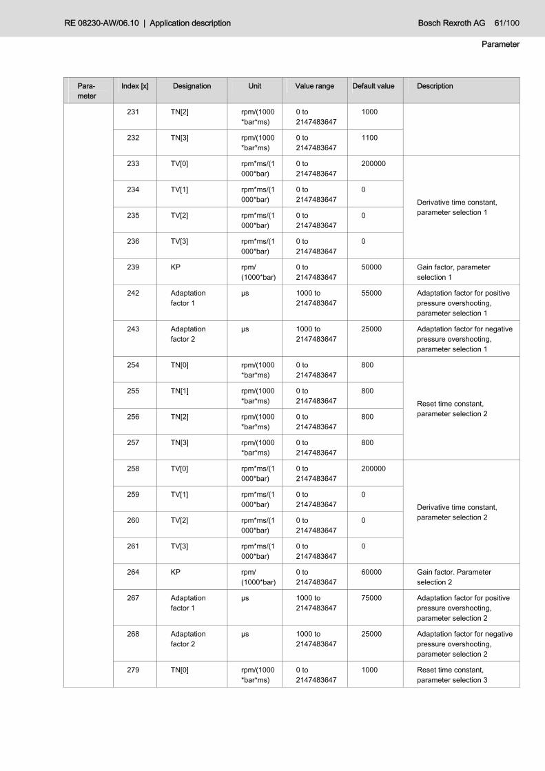
RE 08230-AW/06.10 | Application description Bosch Rexroth AG 61/100
Parameter
Para-meter
Index [x] Designation Unit Value range Default value Description
231 TN[2] rpm/(1000*bar*ms)
0 to 2147483647
1000
232 TN[3] rpm/(1000*bar*ms)
0 to 2147483647
1100
233 TV[0] rpm*ms/(1000*bar)
0 to 2147483647
200000
234 TV[1] rpm*ms/(1000*bar)
0 to 2147483647
0
235 TV[2] rpm*ms/(1000*bar)
0 to 2147483647
0
236 TV[3] rpm*ms/(1000*bar)
0 to 2147483647
0
Derivative time constant, parameter selection 1
239 KP rpm/ (1000*bar)
0 to 2147483647
50000 Gain factor, parameter selection 1
242 Adaptation factor 1
µs 1000 to 2147483647
55000 Adaptation factor for positive pressure overshooting, parameter selection 1
243 Adaptation factor 2
µs 1000 to 2147483647
25000 Adaptation factor for negative pressure overshooting, parameter selection 1
254 TN[0] rpm/(1000*bar*ms)
0 to 2147483647
800
255 TN[1] rpm/(1000*bar*ms)
0 to 2147483647
800
256 TN[2] rpm/(1000*bar*ms)
0 to 2147483647
800
257 TN[3] rpm/(1000*bar*ms)
0 to 2147483647
800
Reset time constant, parameter selection 2
258 TV[0] rpm*ms/(1000*bar)
0 to 2147483647
200000
259 TV[1] rpm*ms/(1000*bar)
0 to 2147483647
0
260 TV[2] rpm*ms/(1000*bar)
0 to 2147483647
0
261 TV[3] rpm*ms/(1000*bar)
0 to 2147483647
0
Derivative time constant, parameter selection 2
264 KP rpm/ (1000*bar)
0 to 2147483647
60000 Gain factor. Parameter selection 2
267 Adaptation factor 1
µs 1000 to 2147483647
75000 Adaptation factor for positive pressure overshooting, parameter selection 2
268 Adaptation factor 2
µs 1000 to 2147483647
25000 Adaptation factor for negative pressure overshooting, parameter selection 2
279 TN[0] rpm/(1000*bar*ms)
0 to 2147483647
1000 Reset time constant, parameter selection 3

62/100 Bosch Rexroth AG Application description | RE 08230-AW/06.10
Parameter
Para-meter
Index [x] Designation Unit Value range Default value Description
280 TN[1] rpm/(1000*bar*ms)
0 to 2147483647
1000
281 TN[2] rpm/(1000*bar*ms)
0 to 2147483647
1000
282 TN[3] rpm/(1000*bar*ms)
0 to 2147483647
1000
283 TV[0] rpm*ms/ (1000*bar)
0 to 2147483647
200000
284 TV[1] rpm*ms/ (1000*bar)
0 to 2147483647
0
285 TV[2] rpm*ms/ (1000*bar)
0 to 2147483647
0
286 TV[3] rpm*ms/(1000*bar)
0 to 2147483647
0
Derivative time constant, parameter selection 3
289 KP rpm/ (1000*bar)
0 to 2147483647
60000 Gain factor, parameter selection 3
292 Adaptation factor 1
µs 1000 to 2147483647
80000 Adaptation factor for positive pressure overshooting, parameter selection 3
293 Adaptation factor 2
µs 1000 to 2147483647
25000 Adaptation factor for negative pressure overshooting, parameter selection 3
400 Offset correction value
mV -10000 to 10000
0
402 Measuring range
rpm/1000 0 to 2147483647
3000000
404 Voltage area mV -10000 to 10000
10000
406 Voltage offset mV -10000 to 10000
0
Standardization for speed command value provision in p/Q control
408 Delay time ms 0 to 2147483647
0 Delay time for speed command value provision in p/Q control
409 Switching threshold
rpm/1000 0 to 2147483647
0 Switching threshold for dead zone element and ramp function for speed command value provision in p/Q control
410 rSlopeRise1 rpm/s 0 to 2147483647
0 Rise (rSlopeRise1) after exceeding the switching threshold in pos. direction for speed command value provision
411 rSlopeRise2 rpm/s 0 to 2147483647
0 Rise (rSlopeRise2) unless rSlopeRise1 for speed command value provision

RE 08230-AW/06.10 | Application description Bosch Rexroth AG 63/100
Parameter
Para-meter
Index [x] Designation Unit Value range Default value Description
412 rSlopeFall1 rpm/s 0 to 2147483647
0 Fall (rSlopeFall1) after exceeding the switching threshold in neg. direction for speed command value provision
413 rSlopeFall2 rpm/s 0 to 2147483647
0 Fall (rSlopeFall2) unless rSlopeFall1 for speed command value provision
414 Voltage range monitoring
mV -10000 to 10000
10000 Maximum permissible deviation from the permissible voltage range for speed command value provision in p/Q control
420 Offset correction value
mV -10000 to 10000
0
422 Measuring range
bar/1000 0 to 2147483647
400000
424 Voltage area mV -10000 to 10000
10000
426 Voltage offset mV -10000 to 10000
0
Standardization for pressure command value provision in p/Q control
428 Delay time ms 0 to 2147483647
0 Delay time for pressure command value provision in p/Q control
429 Switching threshold
mbar 0 to 2147483647
0 Switching threshold for dead zone element and ramp function for pressure command value provision in p/Q control
430 rSlopeRise1 bar/s 0 to 2147483647
0 Rise (rSlopeRise1) after exceeding the switching threshold in pos. direction for pressure command value provision
431 rSlopeRise2 bar/s 0 to 2147483647
0 Rise (rSlopeRise2) unless rSlopeRise1 for pressure command value provision
432 rSlopeFall1 bar/s 0 to 2147483647
0 Fall (rSlopeFall1) after exceeding the switching threshold in neg. direction for pressure command value provision
433 rSlopeFall2 bar/s 0 to 2147483647
0 Fall (rSlopeFall2) unless rSlopeFall1 for pressure command value provision
434 Voltage range monitoring
mV -10000 to 10000
10000 Maximum admissible deviation from the admissible voltage range for pressure command value provision

64/100 Bosch Rexroth AG Application description | RE 08230-AW/06.10
Parameter
Para-meter
Index [x] Designation Unit Value range Default value Description
440 Offset correction value
mV -10000 to 10000
0
442 Measuring range
bar/1000 0 to 2147483647
400000
444 Voltage area mV -10000 to 10000
10000
446 Voltage offset mV -10000 to 10000
0
454 Maximum admissible deviation from the admissible voltage range
mV -10000 to 10000
10000
458 Voltage range for value control after re-start.
mV 0 to 10000 500
Standardization for actual pressure value of pressure
transducer
460 Offset correction value
mV -10000 to 10000
0
462 Measuring range
rpm/1000 0 to 2147483647
3000000
464 Voltage area mV -10000 to 10000
10000
466 Voltage offset mV -10000 to 10000
0
Standardization of speed command value provision in slave operation
474 Voltage range monitoring
mV -10000 to 10000
10000 Maximum admissible deviation from the admissible voltage range for speed command value provision in slave operation
542 Measuring range
bar/1000 0 to 2147483647
400000
544 Voltage area mV -10000 to 10000
10000
546 Voltage offset mV -10000 to 10000
0
Standardization of actual pressure value output
562 Measuring range
rpm/1000 0 to 2147483647
3000000
564 Voltage area mV -10000 to 10000
10000
566 Voltage offset mV -10000 to 10000
0
Standardization of actual speed value output
P-0-1410 - Binary output field
- - - Bit 0: Warning message Bit 1: Error message
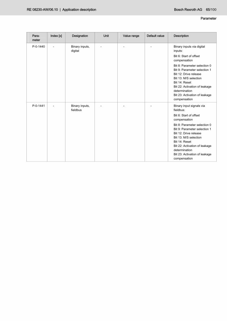
RE 08230-AW/06.10 | Application description Bosch Rexroth AG 65/100
Parameter
Para-meter
Index [x] Designation Unit Value range Default value Description
P-0-1440 - Binary inputs, digital
- - - Binary inputs via digital inputs: Bit 6: Start of offset compensation Bit 8: Parameter selection 0 Bit 9: Parameter selection 1 Bit 12: Drive release Bit 13: M/S selection Bit 14: Reset Bit 22: Activation of leakage determination Bit 23: Activation of leakage compensation
P-0-1441 - Binary inputs, fieldbus
- - - Binary input signals via fieldbus: Bit 6: Start of offset compensation Bit 8: Parameter selection 0 Bit 9: Parameter selection 1 Bit 12: Drive release Bit 13: M/S selection Bit 14: Reset Bit 22: Activation of leakage determination Bit 23: Activation of leakage compensation
66/100 Bosch Rexroth AG Application description | RE 08230-AW/06.10
Commissioning
10 Commissioning In the commissioning, the generally valid safety directives are to be observed. The commissioning may only be performed by specialists. In order to keep the time for the initial commissioning to a minimum, the instructions in the corresponding points are to be observed. For the following commissioning instructions, basic knowledge of the commissioning software "IndraWorks Ds" and the hardware components of the drive controller and the control section are required (see chapter 1.2 "Related documentation"). The procedure shown in the instructions is based on the commissioning software "IndraWorks Ds" (IndraWorks 09V06.0203.09). When using other versions, deviations are possible. In the commissioning, we recommend to proceed as follows:
Upload of the software components to the drive-integrated control section according to chapter 10.1 "Software components upload" using the MMC: – Load firmware according to the application software used – Load application software and corresponding parameter set
Check the hardware settings according to chapter 10.2 "Checking the hardware settings". If the hardware was delivered together with the application software, no changes are necessary and you can skip this point.
Commission the application software according to chapter 10.3 "Commissioning of the application software": – In the condition as supplied, the illustration of the inputs and outputs
according to chapter 10.3.1 "I/O configuration" is correctly assigned with standard parameterization. Therefore, usually no changes are required. We recommend, however, that you check the correct assignment for your application, nonetheless.
– In any case, you should check the configuration and standardization of inputs and outputs and adjust it to the system-specific application, if necessary. For a description refer to chapter 10.3.2 to 10.3.3.
– If the fan control function is used, the parameterization according to chapter 10.3.4 "Fan control" must be made.
– The default parameters provide a functional configuration of pressure control (chapter 10.3.5 "Pressure control") and closed-loop speed control (10.3.6 "Closed-loop speed control"). If there are still instabilities in your system, you must optimize your system according to these two chapters.
The initial condition for the adjustment of the SvP application software is an already existing communication of a PC via the commissioning software "IndraWorks Ds" with the drive-integrated control section. The control section must be connected and switched on according to the wiring specifications (see chapter 8.3 "SvP controller assembly"). The drive controller is in a condition as supplied. The application software with default parameter set as well as the related firmware are already installed on the control section. For the following settings, the drive controller must be in parameterization mode: The possibly necessary switch-over is shown in chapter 7.1 "Modes of operation".
General
Procedure
Initial condition

RE 08230-AW/06.10 | Application description Bosch Rexroth AG 67/100
Commissioning
10.1 Software components upload The software components are supplied with the MMC. The included data are assigned to the corresponding SvP set.
Damage to the hydraulic displacer and to the system, or complete destruction. The incorrect parameterization of an SvP set with the data of another set may result in the uncontrolled operation of the drive which might damage or completely destroy individual components or the system.
Only load MMC data to a SvP set according to the correct assignment.
10.1.1 Firmware loading You can load firmware to the drive-integrated control section with the MMC. The correct firmware for each SvP application is already available on the MMC in the condition as supplied. The following procedure must be observed when loading the firmware:
– Insert the MMC into the corresponding slot X7 at the controller, if not yet done so.
– Restart the drive with inserted MMC! – After the drive is booted, the message "Firmware update?" appears on the
standard operating unit (if this is not the case, please proceed with chapter 10.1.2). Acknowledge this message by pressing the "Enter" key on the operating panel. Now, the inserted MMC loads the firmware to the drive.
– Proceed according to chapter 10.1.2.
10.1.2 Load SvP software and corresponding parameter set In the condition as supplied, the application software and the corresponding parameter set are on the MMC. The following procedure must be observed when loading the software and parameter set:
– After having executed the steps according to chapter 10.1.1, the message "Load param. from MMC" or "Load new param.?", depending on the operating state, is shown on the standard display. Acknowledge this message by pressing the "Enter" key on the operating panel. Now the application software for SvP and the related parameter set for the SvP set are loaded to the drive.
– After the controller is successfully booted, you must remove the MMC. The loading of software and parameters is finished.
NOTE

68/100 Bosch Rexroth AG Application description | RE 08230-AW/06.10
Commissioning
10.2 Checking the hardware settings Changes to the hardware must be communicated to the system according to the following steps. The drive controller must be activated for this purpose. Deactivate the technology function before checking the motor configuration.
For this purpose, click the "Stop" field in the PLC control window. For activation, the corresponding "Run" field has to be actuated. The other settings of the figure are to be checked for correctness and adjusted
accordingly, if necessary.
Fig. 30: Run/Stop of the PLC control
10.2.1 Motor configuration For the application of the SvP software, a motor with integrated encoder is used in the application.
Check whether the drive logs in correctly on the drive-integrated control section via the encoder, and whether the correct cooling type is selected. Normally, you always use a ventilated motor.
Check the motor data according to the following figure.
Fig. 31: Checking the motor configuration
Stop of the drive-integrated PLC

RE 08230-AW/06.10 | Application description Bosch Rexroth AG 69/100
Commissioning
Adjust the motor data accordingly, if the entered data do not comply with the motor. A detailed description is provided in the documentation "Firmware for drive controllers..." in chapter 1.2 "Related documentation".
10.2.2 Field suppressor operation All motors with a Bosch Rexroth encoder have an internal encoder memory by means of which the drive logs in with its parameters on the drive-integrated control section. The configuration of the current and voltage control has a considerable influence on the maximum power of the drive.
Fig. 32: Power increase
Fig. 33: Field suppressor operation
In case that during commissioning, the drive does not achieve the projected power according to the SvP set, you must check the setting of the field suppressor operation of the motor.
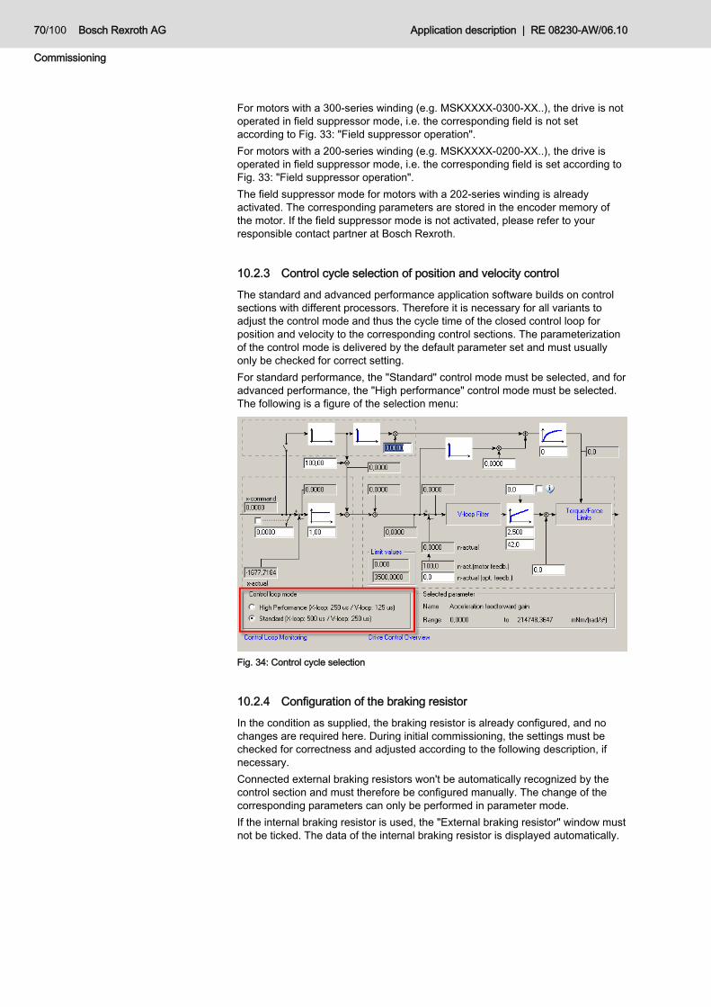
70/100 Bosch Rexroth AG Application description | RE 08230-AW/06.10
Commissioning
For motors with a 300-series winding (e.g. MSKXXXX-0300-XX..), the drive is not operated in field suppressor mode, i.e. the corresponding field is not set according to Fig. 33: "Field suppressor operation". For motors with a 200-series winding (e.g. MSKXXXX-0200-XX..), the drive is operated in field suppressor mode, i.e. the corresponding field is set according to Fig. 33: "Field suppressor operation". The field suppressor mode for motors with a 202-series winding is already activated. The corresponding parameters are stored in the encoder memory of the motor. If the field suppressor mode is not activated, please refer to your responsible contact partner at Bosch Rexroth.
10.2.3 Control cycle selection of position and velocity control
The standard and advanced performance application software builds on control sections with different processors. Therefore it is necessary for all variants to adjust the control mode and thus the cycle time of the closed control loop for position and velocity to the corresponding control sections. The parameterization of the control mode is delivered by the default parameter set and must usually only be checked for correct setting. For standard performance, the "Standard" control mode must be selected, and for advanced performance, the "High performance" control mode must be selected. The following is a figure of the selection menu:
Fig. 34: Control cycle selection
10.2.4 Configuration of the braking resistor
In the condition as supplied, the braking resistor is already configured, and no changes are required here. During initial commissioning, the settings must be checked for correctness and adjusted according to the following description, if necessary. Connected external braking resistors won't be automatically recognized by the control section and must therefore be configured manually. The change of the corresponding parameters can only be performed in parameter mode. If the internal braking resistor is used, the "External braking resistor" window must not be ticked. The data of the internal braking resistor is displayed automatically.

RE 08230-AW/06.10 | Application description Bosch Rexroth AG 71/100
Commissioning
If an external resistor is used, you must enable the "External braking resistor" checkbox in the window and enter the corresponding basic data unless they have been entered correctly. The following is a figure of the entry mask:
Fig. 35: Braking resistor configuration
Further parameter changes are not necessary as these are default parameterizations of the firmware.
10.2.5 Movement limit values
The movement limit values are to be set according to the application. In this connection it is enough to set the bipolar limit, i.e. only one limit for positive and negative direction of rotation is necessary. If the entered limit value is "0", this limit is deactivated.
Damage to the hydraulic displacer or complete destruction. If the hydraulic displacer unit is operated outside the admissible velocity limit, the displacer might be damaged or completely destroyed.
Enter the maximum admissible speed for the hydraulic displacer unit for your application as bipolar limit.
NOTE

72/100 Bosch Rexroth AG Application description | RE 08230-AW/06.10
Commissioning
Fig. 36: Setting the movement limit values
The other entry parameters are to be maintained according to the standard allocation as also shown in the figure.
10.2.6 Torque limit values
The torque limits must be checked and the maximum occurring torque values of a drive must be entered. If the maximum torque/force limit entered manually is too high, it will be limited by its own motor identification to the maximum admissible value, provided that an encoder is used.
Please note that in case you enter the maximum torque limit below the actual limit according to the motor identification, the effected limit is not automatically increased. Refer to the following presentation.
Fig. 37: Checking torque limit values

RE 08230-AW/06.10 | Application description Bosch Rexroth AG 73/100
Commissioning
10.2.7 Checking the correctness of the hardware settings
The mode of operation is switched from parameterization mode to online mode using the pushbuttons in the commissioning software "IndraWorks Ds". Thus it is possible to check, whether configuration is consistent.
Fig. 38: Switch-over between PM and OM
If no errors occur, the system is switched into online mode. If, however, an error message is issued (as illustrated on the following figure), it is not possible to switch into online mode. The control remains in the parameterization mode. The errors according to the error message are to be remedied until no more errors occur and correct start-up into online mode is possible. For information on troubleshooting, please refer to chapter 11 "Troubleshooting".
Fig. 39: Incorrect configuration
10.3 Commissioning of the application software In the condition as supplied, the drive-integrated PLC is activated. If this is not the case or if errors occur, refer to chapter 10.2 "Checking the hardware settings" for the correct start of the PLC. As long as the unit has not been released for drive, you can switch between the operating modes "Parameter mode" and "Online mode" at any time by means of the user interface in "IndraWorks Ds" or on the display of the drive-integrated control section. Application-specific parameters are parameters which are responsible for the function of the application software. They are provided by the list parameter P-0-1389 and processed by the application software. Due to the program runtime of the standard performance variant, value changes of this list parameter might take a moment until the value change is effected. This process is accelerated if there is no drive release.
Activation of the drive-integrated PLC
PM/OM selection
Change of application-specific parameters

74/100 Bosch Rexroth AG Application description | RE 08230-AW/06.10
Commissioning
10.3.1 I/O configuration For changing the I/O configuration, "PM" must be selected as mode of operation. The mapping of I/O at relay X31/X32 is normally according to the following figure, and does not need to be changed by the user if standard parameterization is correctly applied. The correct setting of the parameters has to be checked.
Incorrect function of the software. System components may be damaged or destroyed completely.
Perform the input allocation as shown below. Deviating from the mapping shown below, only perform changes in parameter
P-0-1390 and P-0-1410 according to the description in chapter 9 "Parameter". In case of any more far-reaching changes, you must imperatively contact our
support (chapter 12.2 "Service and support").
Fig. 40: I/O configuration
NOTE

RE 08230-AW/06.10 | Application description Bosch Rexroth AG 75/100
Commissioning
10.3.2 Standardization of analog inputs
Uncontrolled starting of the SvP. The system or individual components might be damaged.
Always parameterize the analog outputs correctly and carefully according to the following description.
For each analog input, the correct standardization must be adjusted according to the applied command value provisions and the applied pressure transducer.
Check the standardization and adjust the parameters to the machine-specific properties, if necessary.
The standard allocation of the parameters necessary for this purpose are provided in the following table.
Table 30: Standardizing the speed command value provision Parameter Setting Unit Description
P-0-1389[402] 3000000 rpm/1000 Measuring range
P-0-1389[404] 10000 mV Voltage range
P-0-1389[406] 0 mV Voltage offset
Check standardization and adjust the parameters to the machine-specific
properties, if necessary. The standard allocation of the parameters necessary for this purpose are
provided in the following table.
Table 31: Standardizing the pressure command value provision Parameter Setting Unit Description
P-0-1389[422] 400000 mbar Measuring range
P-0-1389[424] 10000 mV Voltage range
P-0-1389[426] 0 mV Voltage offset
Check standardization and adjust the parameters to the machine-specific
properties, if necessary. The standard allocation of the parameters necessary for this purpose are
provided in the following table.
Table 32: Standardizing the pressure transducer Parameter Setting Unit Description
P-0-1389[442] 400000 mbar Measuring range
P-0-1389[444] 10000 mV Voltage range
P-0-1389[446] 0 mV Voltage offset
Speed command value provision for pressure/flow control
Pressure command value provision for pressure/flow control
Actual pressure input of pressure transducer for pressure control
Note

76/100 Bosch Rexroth AG Application description | RE 08230-AW/06.10
Commissioning
Check standardization and adjust the parameters to the machine-specific
properties, if necessary. The standard allocation of the parameters necessary for this purpose are
provided in the following table.
Table 33: Standardizing the speed command value provision Parameter Setting Unit Description
P-0-1389[462] 3000000 rpm/1000 Measuring range
P-0-1389[464] 10000 mV Voltage range
P-0-1389[466] 0 mV Voltage offset
10.3.3 Standardization of the analog outputs
Uncontrolled starting of the SvP. The system or individual components might be damaged.
Always parameterize the analog outputs correctly and carefully according to the following description.
Check standardization and adjust the parameters to the machine-specific
properties, if necessary. The standard allocation of the parameters necessary for this purpose are
provided in the following table.
Table 34: Standardizing the actual pressure value Parameter Setting Unit Description
P-0-1389[542] 400000 mbar Measuring range
P-0-1389[544] 10000 mV Voltage range
P-0-1389[546] 0 mV Voltage offset
Check standardization and adjust the parameters to the machine-specific
properties, if necessary. The standard allocation of the parameters necessary for this purpose are
provided in the following table.
Table 35: Standardizing the actual speed value Parameter Setting Unit Description
P-0-1389[562] 3000000 rpm/1000 Measuring range
P-0-1389[564] 10000 mV Voltage range
P-0-1389[566] 0 mV Voltage offset
Speed command value provision for slave operation
Actual pressure value as process-monitoring signal
Actual speed value as process-monitoring signal and actuating signal
for the slave axis
NOTE

RE 08230-AW/06.10 | Application description Bosch Rexroth AG 77/100
Commissioning
10.3.4 Fan control
Insufficient motor cooling The reduction of motor current and related motor power due to overheating results in a power drop.
Use the fan control and parameterize it so that the motor is sufficiently cooled. If the fan control is not used, take system-internal measures for a sufficient
motor cooling.
The "fan control" functionality allows for the temperature-controlled operation of a motor fan. Table 36: Configuring the fan control Parameter Setting Unit Description
P-0-1389[12] 80 °C Switch-on value for fan control
P-0-1389[13] 60 °C Switch-off value for fan control
The control signal is calculated depending on the current motor winding temperature (S-0-0383). If the switch-on threshold is exceeded, the fan is connected and the digital output is set to "0" instead. If the switch-off threshold is undershot, the fan is switched off and the digital output is set to "1". I.e. the output signal is low-active. The output signal of the fan control is assigned to parameter P-0-1419.2 and can be tapped at X32.9 via the digital output.
10.3.5 Pressure control
Uncontrolled movement of the SvP The system or individual components might be damaged.
Always parameterize the closed-loop pressure control correctly and carefully according to the following description.
With the default parameter set, the pressure control is fully functional so that normally, no further optimization is necessary at the pressure controller. If no satisfactory result is achieved for the application with one of the four parameter sets, the following parameters can be used for optimization (examplarily for data set "0"). Table 37: Optimizing the pressure control Parameter Setting Unit Description
P-0-1389[214] 40000 rpm/ (1000*bar) Controller gain
P-0-1389[204] P-0-1389[207]
1000 rpm/(1000*bar*ms) Integral part
P-0-1389[217] 37000 µs Adaptation factor 1
NOTE
NOTE

78/100 Bosch Rexroth AG Application description | RE 08230-AW/06.10
Commissioning
In order to increase the controller gain, parameter P-0-1389[214] must be increased. In case of overshooting or instabilities, the parameter value must be reduced accordingly. In this connection, the limits 10000 to 80000 are to be observed. In case of unstable pressure control conditions, the controller gain in parameter P-0-1389[214] must be reduced. If the control is not stable with values of 20000, the wiring of the pressure transducer has to be checked for correct design and shielding. The control behavior can be checked by the analog outputs for actual pressure and speed value according to chapter 8.3.3 "Analog input and output connection". Using the parameters in P-0-1389[204] and P-0-1389[207], the reset time can be adjusted in the range from 500 to 3000. Reduction of the value provides for a softer control, and increasing the value provides for a more aggressive control. The value must be selected so that the control response of the command value provision is as quick as possible without causing instabilities or overshooting to the system. In order to reduce pressure overshooting in case of steps in the pressure control, the parameter P-0-1389[217] must be increased by 1 ms to 65 ms. As a result of the overshooting reduction, the step response time is delayed; therefore, a good balance between overshooting and reaction time has to be found.
10.3.6 Closed-loop speed control
Uncontrolled movement of the SvP. The system or individual components may be damaged.
Always parameterize the closed-loop speed control correctly and carefully according to the following description.
The parameters of the speed control loop in the control section are pre-allocated. Depending on the application in a system, it may be necessary to adjust the parameterization. For the optimization of the speed control loop it is necessary to get into closed-loop control in order to be able to set an optimum of parameters. The procedure is described in the following. The speed controller optimization is started using the default parameters of the condition as supplied. By selecting the digital input X31.3, the release is actuated and the command value provisions are complied with. Via the parameters S-0-0100 (velocity controller proportional gain) and S-0-0101 (velocity controller reset time), the correct parameterization has to be performed as follows according to the application and the hardware components used. In pressure holding mode at minimum pressure (5 bar), the speed has to be optimized. The limit for S-0-0100 must be determined acoustically, i.e. the ideal value is the highest value possible at which the motor is still running quietly without getting unstable (start optimization with a value of "2", maximum admissible value is "4"). This determination is performed with S-0-0101=0. After determination of S-0-0100, a value of "40" is entered in S-0-0101.
NOTE

RE 08230-AW/06.10 | Application description Bosch Rexroth AG 79/100
Troubleshooting
11 Troubleshooting
11.1 Fault finding procedure Always work systematically and focused, even when under time pressure.
Random and imprudent disassembly and readjustment of settings might result in the inability to restore the original error cause.
First get a general idea of how your product works in conjunction with the entire system.
Try to find out whether the product has worked properly in conjunction with the entire system before the error occurred first.
Try to determine any changes of the entire system in which the product is integrated:
– Were there any changes to the product's operating conditions or operating range?
– Were there any changes or repair works on the entire system (machine/system, electrics, control) or on the product? If so: What were they?
– Was the product or machine used as intended? – How did the malfunction become apparent? Try to get a clear idea of the cause of the fault. Directly ask the (machine)
operator, if necessary. Document the error condition and compare it to the initial condition. You can
use the form in chapter 12.3 "Service and support form" for this purpose.
11.2 Diagnostic messages and function The drive controller performs a number of diagnostic functions as a standard. They can basically divided into four groups: • Drive controller error (from firmware) • Drive controller warning (from firmware) • Application error (from application software) • Application warning (from application software) Diagnostic messages are shown in the display. A precise description of the error cause is given in hexadecimals in parameter PA-0-1372. Fig. 41: shows the included information.
Description column
Example: F A 4 4 0 0
1 2 3 4 5 6
= P-0-1372 (hexadecimal )
1. Error display
1.1 FA… = Error message of the application
2. Error source
2.1 44…= component
3. reserved
3.1 00…= dumm y
0 2
7 8
4. Fehlerursache
4.1 02…= Data set is not compatibleor checksum not right Fig. 41: Error coding
General
Display

80/100 Bosch Rexroth AG Application description | RE 08230-AW/06.10
Troubleshooting
For the communication of the error and/or warning data to a superior control, bits "0" and/or "1" are set in parameter P-0-1410 according to Table 38:. If necessary, they can be assigned to digital outputs or a fieldbus. Table 38: Display of the application errors Parameter Description
P-0-1372 Coded display of the error cause.
P-0-1410 Bit 0: Warning message bit Bit 1: Error message bit
11.2.1 Drive controller error If a drive controller error occurs, the diagnosis message "Fxxxx" is generated and the torque for the drive is immediately disengaged. If a drive error occurs, it is indicated in parameter P-0-1372 with "FA450001", and the digital output X32.7 (P-0-1410.1) is set to "H".
11.2.2 Drive controller warnings If a drive controller warning occurs, the diagnostic message "Exxxx" is generated. The drive system keeps on working normally in this state. Warnings are indicated in parameter P-0-1410.0 with the value "1". In the standard allocation, this information is not allocated to a digital output.
11.2.3 Application error If an application error occurs, the diagnosis message "F2011 SPS error no. 1" is generated and the torque for the drive is immediately disengaged. The initially tripping error is indicated in parameter P-0-1372, and the digital output X32.7 (P-0-1410.1) is set to "H". You can assign the precise error cause to the error code in parameter P-0-1372. For error processing, please see chapter 11.3 "Description of the application-specific errors and warnings".
11.2.4 Application warning If an application-specific warning occurs, the diagnostic message "E2011 PLC warning no. 1" is generated. The system keeps on working normally in this state. Warnings are indicated in parameter P-0-1410.0 with the value "1". In the standard allocation, this information is not allocated to a digital output. You can assign the precise warning cause to the error code in parameter P-0-1372. For error processing, please see chapter 11.3 "Description of the application-specific errors and warnings". If no warning cause is assigned, the warning output as well as the message in parameter P-0-1372 will go out after 2.5 s.

RE 08230-AW/06.10 | Application description Bosch Rexroth AG 81/100
Troubleshooting
11.3 Description of the application-specific errors and warnings
The following sections are a description of the most important application-specific errors and/or warnings when using servo-variable pump drives in p/Q control. Besides the description of the faulty condition, the list also includes information on the possible causes and remedies. The following errors and/or warnings might occur:
– Drive controller error or warning – Cable break detection - Actual pressure value signal – Cable break detection - Speed command value provision – Cable break detection - Speed command value signal (slave) – Cable break detection - Pressure command value signal – Pressure transducer monitoring – Checksum error – Parameter change not admissible – List element from P-0-1389 is outside the admissible range – Faulty conditions in the state machine – Insufficient control quality
11.3.1 FA450001 drive controller error
The application software is notified drive controller errors via the status word P-0-0115.13 of the device control. The type of error is shown on the display of the drive controller in format "Fxxxx". The torque of the drive is disengaged at the same time. • The error cause is shown on the display with "Fxxxx". • The drive controller disengages the torque of the drive. • Parameter P-0-1410, bit "1" indicates the occurrence of an error. • Parameter P-0-1372 indicates the occurrence of a drive error with "FA450001".
The cause is indicated in the error display, and measures must be taken according to the operating instructions. For troubleshooting, please follow the instructions in the "Operating instructions - Rexroth IndraDrive C; drive controllers HCS02.1, HCS03.1" mat. no. R911314904. According to the description for each monitoring function in the firmware "Rexroth IndraDrive - firmware for drive controllers; functional description" mat. no. R911315484.
11.3.2 FA450002 drive controller warning The application software is notified drive controller warnings via the status word P-0-0115.2 of the device control. The type of warning is shown on the display of the drive controller in format "Exxxx". The drive system keeps on working normally in this state. The reaction depends on the type of warning of the drive controller. The drive controller does not perform any drive reaction. If the system is operated despite a pending warning, an error may be generated in the further course of generation. If the drive controller warning goes out, the warning in parameter P-0-1410.0 is deleted after 2.5 s.
Description
Reaction
Cause
Countermeasures
Setting parameters
Description
Reaction

82/100 Bosch Rexroth AG Application description | RE 08230-AW/06.10
Troubleshooting
• The warning cause is shown on the display with "Exxxx". • Parameter P-0-1410, bit "0" shows the occurrence of a warning. • Parameter P-0-1372 indicates the occurrence of a drive warning with
"FA450002".
The cause must be discussed in more detail on the basis of the the warning display. For the warning handling, please follow the instructions in the "Operating instructions - Rexroth IndraDrive C; drive controllers HCS02.1, HCS03.1" mat. no. R911314904. According to the description for each monitoring function in the firmware "Rexroth IndraDrive - firmware for drive controllers; functional description" mat. no. R911315484.
11.3.3 FA0D0004 cable break detection - Actual pressure value signal
This function is deactivated for the SvP application in the default parameter set and can be activated, if necessary. For this purpose, please refer to your responsible contact partner at Bosch Rexroth.
Tolerance range in the voltage range too large. Deviations from the admissible voltage range are recognized as error too late. The error detection of hardware defects can only be performed restrictedly.
– Incorrect command and actual values – Incorrect increase times of pressure and speed – incorrect closed-loop speed control – Incorrect actuating signal to the electric drive – Incorrect machine function (e.g. pressure too high, pressure too low, negative
rotation of the hydraulic displacer and cavitation)
Always select the tolerance range as small as possible.
The application software cyclically checks the actual pressure value channel for deviations from the specified voltage range. If the voltage range plus a parameterizable tolerance (P-0-1389[454]) is left, the diagnosis message "F2011 PLC error no. 1" is generated. • The torque for the drive is immediately disengaged. • Parameter P-0-1410, bit "1" indicates the occurrence of an error. • Parameter P-0-1372 indicates the occurrence of a cable break at the actual
pressure value input with "FA0D0004".
Causes for error messages might be: • Cable break • Incorrect connection • Incorrect cable shielding • Incorrect standardization
Check the plug-in connections for tight seat, contamination or incorrect connection. Immediately remove any defects.
Check signal cable and signal shielding. Immediately remove any defects. Check the standardization. Correct the standardization.
Cause
Countermeasure
Setting parameters
Description
Reaction
Cause
Countermeasures
NOTE

RE 08230-AW/06.10 | Application description Bosch Rexroth AG 83/100
Troubleshooting
The parameterization can be used to individually determine as of which voltage range deviation an error message is issued. Table 39: Parameters for cable break detection - Actual pressure value signal Parameter Setting Unit Description
P-0-1389[454] 10000 mV Maximum admissible deviation from the admissible voltage range
11.3.4 FA010004 cable break detection - Speed command value provision
This function is deactivated for the SvP application in the default parameter set and can be activated, if necessary. For this purpose, please refer to your responsible contact partner at Bosch Rexroth. The application software cyclically checks the speed command value provision for deviations from the specified voltage range. If the voltage range plus a parameterizable tolerance (P-0-1389[414]) is left, the diagnosis message "F2011 PLC error no. 1" is generated. • The torque for the drive is immediately disengaged. • Parameter P-0-1410, bit "1" indicates the occurrence of an error. • Parameter P-0-1372 indicates the occurrence of a cable break at the actual
pressure value input with "FA010004".
Causes for error messages might be: • Cable break • Incorrect connection • Incorrect cable shielding • Incorrect standardization
Check the plug-in connections for tight seat, contamination or incorrect connection. Immediately remove any defects.
Check signal cable and signal shielding. Immediately remove any defects. Check the standardization. Correct the standardization.
The parameterization can be used to individually determine as of which voltage range deviation an error message is issued.
Tolerance range in the voltage range too large. Deviations from the admissible voltage range are recognized as error too late. The error detection of hardware defects can only be performed restrictedly.
– Incorrect command and actual values – Incorrect increase times of pressure and speed – incorrect closed-loop speed control – Incorrect actuating signal to the electric drive – Incorrect machine function (e.g. pressure too high, pressure too low, negative
rotation of the hydraulic displacer and cavitation)
Always select the tolerance range as small as possible.
Setting parameters
Description
Reaction
Cause
Countermeasures
Setting parameters
NOTE

84/100 Bosch Rexroth AG Application description | RE 08230-AW/06.10
Troubleshooting
Table 40: Parameters for cable break detection - Speed command value provision Parameter Setting Unit Description
P-0-1389[414] 10000 mV Maximum admissible deviation from the admissible voltage range
11.3.5 FA130004 cable break detection - Speed command value signal (slave)
This function is deactivated for the SvP application in the default parameter set and can be activated, if necessary. For this purpose, please refer to your responsible contact partner at Bosch Rexroth. The application software cyclically checks the pressure command value channel for deviations from the specified voltage range. If the voltage range plus a parameterizable tolerance (P-0-1389[474]) is left, the diagnosis message "F2011 PLC error no. 1" is generated. • The torque for the drive is immediately disengaged. • Parameter P-0-1410, bit "1" indicates the occurrence of an error. • Parameter P-0-1372 indicates the occurrence of a cable break at the actual
pressure value input with "FA130004".
• Cable break • Incorrect connection • Incorrect cable shielding • Incorrect standardization
Check the plug-in connections for tight seat, contamination or incorrect connection. Immediately remove any defects.
Check signal cable and signal shielding. Immediately remove any defects. Check the standardization. Correct the standardization.
The parameterization can be used to individually determine as of which voltage range deviation an error message is issued.
Tolerance range in the voltage range too large. Deviations from the admissible voltage range are recognized as error too late. The error detection of hardware defects can only be performed restrictedly.
– Incorrect command and actual values – Incorrect increase times of pressure and speed – incorrect closed-loop speed control – Incorrect actuating signal to the electric drive – Incorrect machine function (e.g. pressure too high, pressure too low, negative
rotation of the hydraulic displacer and cavitation)
Always select the tolerance range as small as possible.
Table 41: Parameter for cable break detection - Speed command value signal Parameter Setting Unit Description
P-0-1389[474] 10000 mV Maximum admissible deviation from the admissible voltage range
Description
Reaction
Cause
Countermeasures
Setting parameters
NOTE

RE 08230-AW/06.10 | Application description Bosch Rexroth AG 85/100
Troubleshooting
11.3.6 FA070004 cable break detection - Pressure command value signal
This function is deactivated for the SvP application in the default parameter set and can be activated, if necessary. For this purpose, please refer to your responsible contact partner at Bosch Rexroth. The application software cyclically checks the pressure command value channel for deviations from the specified voltage range. If the voltage range plus a parameterizable tolerance (P-0-1389[434]) is left, the diagnosis message "F2011 PLC error no. 1" is generated. • The torque for the drive is immediately disengaged. • Parameter P-0-1410, bit "1" indicates the occurrence of an error. • Parameter P-0-1372 indicates the occurrence of a cable break at the actual
pressure value input with "FA070004".
• Cable break • Incorrect connection • Incorrect cable shielding • Incorrect standardization
Check the plug-in connections for tight seat, contamination or incorrect connection. Immediately remove any defects.
Check signal cable and signal shielding. Immediately remove any defects. Check the standardization. Correct the standardization.
The parameterization can be used to individually determine as of which voltage range deviation an error message is issued.
Tolerance range in the voltage range too large. Deviations from the admissible voltage range are recognized as error too late. The error detection of hardware defects can only be performed restrictedly.
– Incorrect command and actual values – Incorrect increase times of pressure and speed – Incorrect closed-loop speed control – Incorrect actuating signal to the electric drive – Incorrect machine function (e.g. pressure too high, pressure too low, negative
rotation of the hydraulic displacer and cavitation)
Always select the tolerance range as small as possible.
Table 42: Parameter for cable break detection - Pressure command value signal Parameter Setting Unit Description
P-0-1389[434] 10000 mV Maximum admissible deviation from the admissible voltage range
Description
Reaction
Cause
Countermeasures
Setting parameters
NOTE

86/100 Bosch Rexroth AG Application description | RE 08230-AW/06.10
Troubleshooting
11.3.7 FA4A0001 pressure transducer monitoring The voltage signal for the pressure transducer at the input is checked by switching on the SvP application. If the input value is above the voltage offset value (P-0-1389[446]) plus a tolerance range (P-0-1389[458]), or below the voltage offset value minus the tolerance range, a diagnosis message "F2011 PLC error no. 1" is generated. • The drive cannot be switched to "AU/DR". • Parameter P-0-1410, bit "1" indicates the occurrence of an error. • Parameter P-0-1372 indicates the occurrence of a voltage deviation at the
actual pressure value input with "FA4A0001".
• Faulty standardization of the pressure transducer • Incorrect pressure transducer connected • Cable break • Pressure transducer not correctly connected
Check the type of pressure transducer Check the wiring of the pressure transducer Check the standardization. Correct the standardization.
The parameterization can be used to individually determine as of which voltage range deviation an error message is issued.
Tolerance range in the voltage range too large. Deviations from the admissible voltage range are recognized as error too late. The error detection of hardware defects can only be performed restrictedly.
– Incorrect command and actual values – Incorrect increase times of pressure and speed – Incorrect closed-loop speed control – Incorrect actuating signal to the electric drive – Incorrect machine function (e.g. pressure too high, pressure too low, negative
rotation of the hydraulic displacer and cavitation)
Always select the tolerance range as small as possible.
Table 43: Parameters for pressure transducer monitoring Parameter Setting Unit Description
P-0-1389[446] 0 mV Voltage offset for pressure transducers
P-0-1389[458] 500 mV Tolerance range around voltage offset for input check after start-up
Description
Reaction
Cause
Countermeasures
Setting parameters
NOTE

RE 08230-AW/06.10 | Application description Bosch Rexroth AG 87/100
Troubleshooting
11.3.8 FA440002 checksum error There is a value error in the parameter list of P-0-1389. • The application software does not allow for operation because the parameters
might be faulty. • Parameter P-0-1372 indicates the occurrence of a checksum error with the
error message "FA440002".
• Offline parameterization without authorization was performed • Data loss or damage during data transfer
Check parameter P-0-1389 in the parameter set and replace it with a valid parameter set, if necessary.
If an invalid parameter set must be changed to a valid status, this must be performed with checksum calculation according to chapter 7.2 ".Command management"
See chapter 7.2 "Command management"
11.3.9 FA440004 parameter change not admissible
The user makes a parameter change in list parameter P-0-1389 which does not comply with his authorization status. • The changed parameter is not accepted. • Parameter P-0-1372 indicates the occurrence of an unauthorized parameter
change with the error message "FA440004". • Parameter P-0-1410, bit "0" shows the occurrence of a warning.
• A parameter change was made without having the adequate authorization. • Log in on the adequate authorization level if you want to change the parameter,
or refer to your responsible contact partner at Bosch Rexroth. -
11.3.10 FA440008 list element from P-0-1389 is outside the admissible range
Description of list elements of P-0-1389 with values outside the admissible value range. • The parameter values outside the admissible value range are not accepted. • Replacement values instead of the indicated values are effective (usually the
corresponding limits) • Parameter P-0-1372 indicates the occurrence of an unauthorized parameter
change with the error message "FA440008". • Parameter P-0-1410, bit "0" shows the occurrence of a warning. • P-0-1371 indicates the index of the list element of P-0-1389 which is outside the
valid range.
• One or more list elements of P-0-1389 are outside the maximum admissible limits.
• Change the invalid value into a valid value within the admissible limits.
-
Description Reaction
Cause
Countermeasures
Setting parameters
Description
Reaction
Cause Countermeasures
Setting parameters
Description
Reaction
Cause
Countermeasures
Setting parameters

88/100 Bosch Rexroth AG Application description | RE 08230-AW/06.10
Troubleshooting
11.3.11 FA440001..FA470080 Faulty conditions of the operating mode selection
Errors occur in the operating mode selection of the application software. • The torque for the drive is immediately disengaged. • Parameter P-0-1410, bit "1" indicates the occurrence of an error. • Parameter P-0-1372 indicates the occurrence of an error in the state machine
with the error messages from "FA470001" to "FA470080".
• Faulty parameterization of parameter P-0-1389 • List parameter P-0-1389 does not contain list elements
Check parameter P-0-1389 for correct parameterization. Load a valid parameter set.
See chapter 9 "Parameter".
11.3.12 Insufficient control quality
The control behavior in pressure and speed does not satisfy the system requirements and is possibly even instable. The application software recognizes an insufficient control behavior and cannot perform a specific error reaction. • Not optimal parameterization of the pressure control • Not optimal parameterization of the closed-loop speed control • Machine cycle does not correspond to the design of the hydraulic and/or
electrical system
Check the parameterization of the pressure and closed-loop speed control with the standard parameterization according to chapter 10.3.5 "Pressure control" and 10.3.6 "Closed-loop speed control". If necessary, the control parameters have to be adjusted to the specific system behavior.
Check the machine cycle and adjust it.
See chapter 9 "Parameter".
Instable system behavior The system or components might be damaged.
Adjust the parameterization of the pressure and closed-loop speed control according to chapter 10.3.5 "Pressure control" and 10.3.6 "Closed-loop speed control".
For the setting of the pressure and closed-loop speed control deviating from the default parameters refer to chapters 10.3.5 "Pressure control" and 10.3.6 "Closed-loop speed control".
Description
Reaction
Cause
Countermeasures
Setting parameters
Description
Reaction
Cause
Countermeasures
Setting parameters
NOTE

RE 08230-AW/06.10 | Application description Bosch Rexroth AG 89/100
Appendix
12 Appendix
12.1 Wiring diagrams
12.1.1 General
For the general connection wiring of the "IndraDrive", refer to the following hardware documentation (project planning): • Power section "IndraDrive C"
DOK-INDRV*-HCSxx.1****-PRxx-DE-P • Control section
DOK-INDRV*-CSH********-PRxx-DE-P
12.1.2 Input/output allocation at the base plate
The following two tables show the standard allocation of the I/O signals to the plug-in connectors X31 and X32 of the base plate. Table 44: Parameters for pressure transducer monitoring PIN I/O Function Parameter Bit no.
1 O ro relay Rel(a)
2 O ro relay Rel(b) P-0-0861 9
3 I Enable Drive P-0-1440 12
4 I Setting parameter set - PS0 P-0-1440 8
5 I Setting parameter set - PS1 P-0-1440 9
6 I Master-slave switch-over P-0-1440 13
7 I Activate leakage correction P-0-1440 23
8 PWR Uext - -
9 PWR GNDext - -
Table 45: Plug-in connector X32 PIN I/O Function Parameter Bit no.
1 Analog output 1 1) - -
2 Analog output 2 1) - -
3 Analog_GND 1) - -
4 Analog input 1 U+ 1) S-0-0000 -1
5 Analog input 1 U- 1) S-0-0000 -1
6 O Fan control P-0-1419 2
7 O Error output P-0-1410 1
8 I Error reset P-0-1440 14
9 O Double pump selection P-0-1410 3 1) This signal is only allocated in case of "IndraDrive Advanced" drive controllers.

90/100 Bosch Rexroth AG Application description | RE 08230-AW/06.10
Appendix
12.1.3 Analog I/O extension MA1
This option module is used in order to increase the number of analog channels or to equip control sections with analog channels of better resolution. The option provides the following functions: • 2 differential analog input channels ±10 V (resolution: 10 bit) • 2 analog input channels ±10 V (resolution: 12 bit)
Table 46: Connection point MA1 Connection point Type Number
of poles Design Multi-wire [mm2]
- D-Sub 15 Socket at the device 0,08 – 0,5
Table 47: Pinout MA1 PIN designation Description Assignment
8 Housing Housing earthing -
15 GNDA Reference potential
7 GND100 Shield connection
14 +AA2 Signal line
Analog output 2 (current motor speed)
6 GNDA Reference potential
13 GND100 Shield connection
5 +AA1 Signal line
Analog output 1 (current actual pressure value)
12 GNDA not connected
4 +AE2 Signal line
11 -AE2 Reference potential
3 GND100 Shield connection
Analog input 2 (speed command value)
10 GNDA not connected
2 +AE1 Signal line
9 -AE1 Reference potential
1 GND100 Shield connection
Analog input 1 (pressure command value)
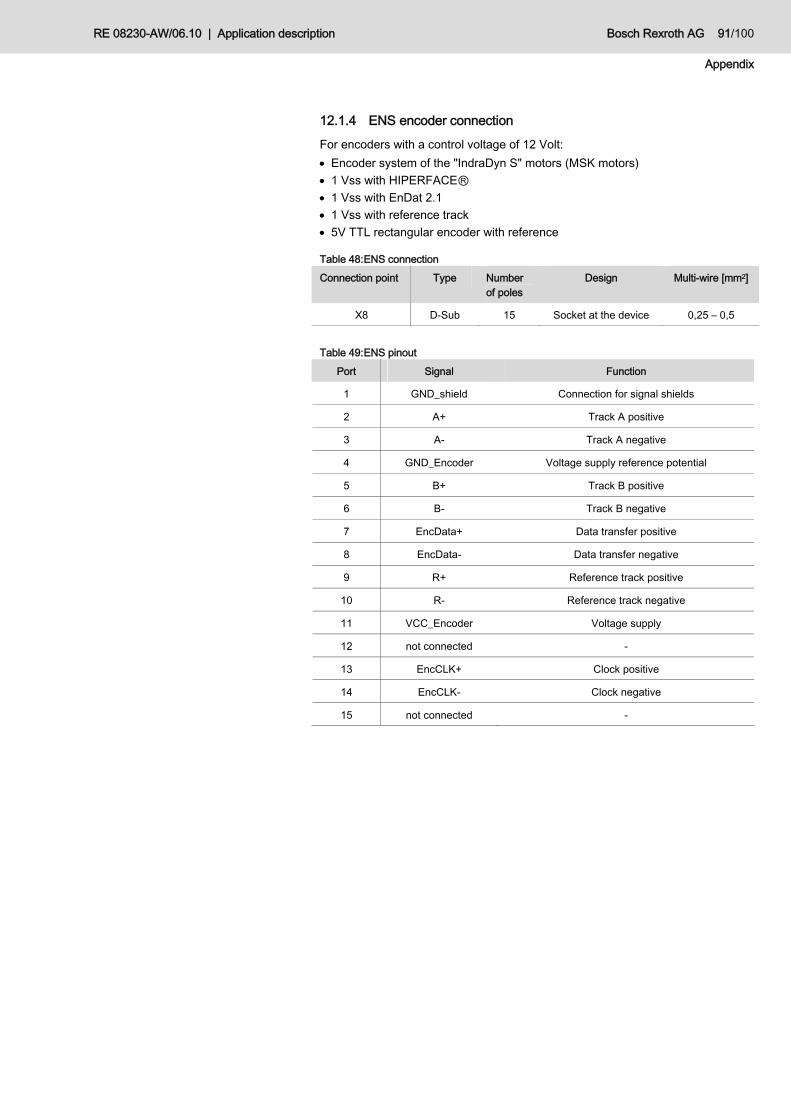
RE 08230-AW/06.10 | Application description Bosch Rexroth AG 91/100
Appendix
12.1.4 ENS encoder connection
For encoders with a control voltage of 12 Volt: • Encoder system of the "IndraDyn S" motors (MSK motors) • 1 Vss with HIPERFACEⓇ • 1 Vss with EnDat 2.1 • 1 Vss with reference track • 5V TTL rectangular encoder with reference
Table 48: ENS connection Connection point Type Number
of poles Design Multi-wire [mm2]
X8 D-Sub 15 Socket at the device 0,25 – 0,5
Table 49: ENS pinout
Port Signal Function
1 GND_shield Connection for signal shields
2 A+ Track A positive
3 A- Track A negative
4 GND_Encoder Voltage supply reference potential
5 B+ Track B positive
6 B- Track B negative
7 EncData+ Data transfer positive
8 EncData- Data transfer negative
9 R+ Reference track positive
10 R- Reference track negative
11 VCC_Encoder Voltage supply
12 not connected -
13 EncCLK+ Clock positive
14 EncCLK- Clock negative
15 not connected -

92/100 Bosch Rexroth AG Application description | RE 08230-AW/06.10
Appendix
12.2 Service and support
12.2.1 Country representations
Please contact your personal account manager first. If you do not have a personal account manager, please contact the next sales organization. For the corresponding contact data, please refer to chapter 12.2.2 "Internet contact".
12.2.2 Internet contact
For additional information on service, repair and training as well as the current addresses of our sales organizations please refer to: http://www.boschrexroth.com
12.2.3 Preparation of information We can help you in a fast and efficient way if you keep the following information available: • Detailed description of the failure and the boundary conditions • Information on the name plate of the products concerned, particularly type key
and serial numbers • Phone, fax numbers and email address under which you are available in case
of enquiries.
A template for the easy and fast collection of information regarding your request is shown in a questionnaire in annex 12.3. You can use it for the quick and easy documentation of your problem and send it to us. On the basis of this information we will process your request quickly and efficiently.

RE 08230-AW/06.10 | Application description Bosch Rexroth AG 93/100
Appendix
12.3 Service and support form As basis of the system analysis of an application, it is necessary to query the basic conditions and sometimes even more application-specific details. This information allows for the simplification and acceleration of the error analysis/troubleshooting. By answering the following questions, a compact system overview can be provided. Please tick or fill in the specified lines if they apply to you.
12.3.1 Customer information
Company name: __________________________________ Address: __________________________________ __________________________________ __________________________________ Phone no.: __________________________________ Email: __________________________________ Contact partner: __________________________________ Name: __________________________________ Phone no.: __________________________________ Email: __________________________________
12.3.2 System information
Which type of application is concerned? Injection molding machine Other: __________________________________________ Designation, if applicable: ______________________(incl. tonnage) Which control types are to be covered by SvP? Flow control (Q) Pressure control (p) substitutional pressure/flow control (p/Q) Other: __________________________________________ Mains voltage: __________ [V] (e.g. 230 V) Tolerance: ________ (e.g. +/-10%) Ambient temperature :__________________________ [°C] Compression medium :__________________________ (e.g. HLP46) Place of installation :__________________________ (e.g. D-Lohr) Special framework conditions: (e.g. installation height, etc.)_________________________ ________________________________________________________________________ ________________________________________________________________________ ________________________________________________________________________
General
Company data
Account manager
General system information
Framework conditions

94/100 Bosch Rexroth AG Application description | RE 08230-AW/06.10
Appendix
12.3.3 System behavior
Please specify the machine cycle below, specifying the chronological order of the components involved in the process (p, Q, valve positions, etc.; measurement records, if applicable, with the internal oscilloscope function in "IndraWorks Ds"):
Minimum required data: p: Pressure command value, actual pressure value Q: Flow command value, actual command value V: Valve switching behavior(e. g. injection valve)
RE 08230-AW/06.10 | Application description Bosch Rexroth AG 95/100
Appendix
Specify the hydraulic structure of the system (e.g. hydraulic circuit diagram or sketch; place of installation of the pressure transducer, check valves, if applicable, structure of suction range):
Are there any particularities?
________________________________________________________________________ ________________________________________________________________________ ________________________________________________________________________
12.3.4 Control communication Designation of the command communication (CCM):________________ (e.g. L40) Medium for command value provision: ____________________________ (e.g. analog)

96/100 Bosch Rexroth AG Application description | RE 08230-AW/06.10
Appendix
12.3.5 Special functions
Is the fan control used?* yes no Is the leakage correction used?* yes no Is master-slave used?* yes no (*can be seen from the complete parameter storage)
12.3.6 Technical data of the integrated system
SvP product identification : _______________________________________________ (e.g. FWS-MLDTFA-SVP-01V19-D0-IMM-48H2)
Motor identification* : _______________________________________________ Frequency converter* : _______________________________________________ Control section* : _______________________________________________ Firmware* : _______________________________________________ (*can be seen from the complete parameter storage)
Pump : _______________________________________________ Pressure transducer : _____________________________ (e.g. HM17-..) Is a braking resistor used? yes no if yes, identification: _______________________ Is a throttle used? yes no if yes, identification: _______________________ Is a mains filter used? yes no if yes, identification: _______________________
12.3.7 Technical data of the integrated software
Software version* : ____________________________________ (SXXVXXRXX) (*can be seen from the complete parameter storage)
In every troubleshooting, it is advantageous to perform a measurement with significant content with regard to the problem. Measurement records can be prepared using the internal oscilloscope function of "IndraWorks Ds". When recording the measurement please make sure to present the problem both in connection with the the whole cycle and in detail for precise analysis. In case of a support enquiry, you must in any case perform a complete parameter storage including all parameters available in the drive controller and provide it to the contact person.

RE 08230-AW/06.10 | Application description Bosch Rexroth AG 97/100
Alphabetical index
13 Alphabetical index
A Abbreviations 10 Analog I/O extension MA1 90 Analog input and output connection 54 Application controller 41
C Checking the correctness of the
hardware settings 73 Command management 27 Commissioning 66 Commissioning of the application
software 73 Component overview 19 Configuration of the braking resistor
70 Control cycle selection 70
D Dead zone function 46 Description of the application-specific
errors and warnings 81 Diagnosis
Application error 80 Application warning 80 Drive controller error 80 Drive controller warnings 80
Diagnostic messages and function 79 Documentation
Related documents 8 validity 5
Double pump selection 32
E ENS encoder connection 54, 91 Error
Cable break detection FA010004 83 FA070004 85 FA0D0004 82 FA130004 84
General FA440001..FA470080 88 FA440002 87 FA440004 87 FA440008 87 FA450001 81 FA450002 81 FA4A0001 86 Inadequate control quality 88
F Fan control 77 Fault finding procedure 79 Field suppressor operation 69 Fieldbus 36 Firmware loading 67 Functional description 23
G General safety instructions 13
H Hardware settings 68
I I/O configuration 74 Identification of software and parameter
set 20 IndraWorks Ds 22 Input/output allocation at the base plate
89 Inputs / outputs 45 Installation 50
Required accessories 50
L Leakage compensation 35 Load SvP software and corresponding
parameter set 67
M Main DvP features 16 Master-Slave 33 Minimum command values 49 Mode of operation
Automatic mode 26 Error mode 27 Parameter mode 25 Standby operation 25
Modes of operation 23 Motor configuration 68 Motor fan control 32 Movement limit values 71
O Offset correction 38 Optimization
Adaptation factor 44 Derivative time 44 reset time 42
Optimization Gain 41
P Parameter 56
P-0-0228 56 P-0-0229 56 P-0-0300 56 P-0-0302 57 P-0-0420 57 P-0-0423 57 P-0-0640 57 P-0-0858 57

98/100 Bosch Rexroth AG Application description | RE 08230-AW/06.10
Alphabetical index
P-0-0860 58 P-0-1203 58 P-0-1213 58 P-0-1300 58 P-0-1301 58 P-0-1370 58 P-0-1371 58 P-0-1372 58 P-0-1389 59 P-0-1410 64 P-0-1440 65 P-0-1441 65 S-0-0091 56 S-0-0100 56 S-0-0101 56 S-0-0383 57
Parameter adjustment 39 Adjustment to system pressure 40 to system rigidity 39
Pressure transducer connection 54 Product- and technology-related safety
instructions 14
Q Qualification of personnel 13
R Ramp functionality 47 Required accessories 50 Required tools 50
S Safety instructions 11 Scope of delivery 16 Service and support
Form 93 General 92
Software components upload 67 Standardization
analog inputs 75 analog outputs 76 analog inputs and outputs 45 Closed-loop speed control 78 Pressure control 77
SvP controller assembly 51
T Torque limit values 72 Transport and storage 21
Software 21 Troubleshooting 79
U Use
as intended 11 not as intended 13
W Wiring diagrams 89

RE 08230-AW/06.10 | Application description Bosch Rexroth AG 99/100
Alphabetical index

Bosch Rexroth AG Zum Eisengießer 1 D-97816 Lohr am Main Germany [email protected] www.boschrexroth.com
NPrinted in Germany. RE 08230-AW/06.10
![Troubleshooting Wonderware Application Server …...Troubleshooting Wonderware Application Server Bootstrap Communications file:///C|/inetpub/9/12/2012 3:42:34 PM] Tech Note 876 ...](https://static.documents.pub/doc/80x56/5f0cfedf7e708231d438288a/troubleshooting-wonderware-application-server-troubleshooting-wonderware-application.jpg)


