Metall. Res. Technol. 112, 605 (2015) c EDP Sciences, 2015 DOI: 10.1051/metal/2015039 www.metallurgical-research.org Metallurgical Research & Technology Application study of AlSi10Mg alloy by selective laser melting: physical and mechanical properties, microstructure, heat treatments and manufacturing of aluminium metallic matrix composite (MMC) Arnold Mauduit, Sébastien Pillot and François Frascati CETIM CERTEC (CRAl: centre de référence de l’aluminium, Pole matériaux et procédés), 9 Boulevard Lahitolle, 18000 Bourges, France e-mail: [email protected]Key words: Selective laser melting; AlSi10Mg; MMC; SiC; microstructure; heat treatments; physical and mechanical properties Received 9 March 2015 Accepted 24 S ptember 2015 Abstract – Samples of AlSi10Mg alloy were first constructed, selecting the manufactur- ing parameters through a parametric method based on an experimental design; with the same technique, samples of a metallic matrix composite (AlSi10Mg matrix base and parti- cles of SiC reinforcements) were also made. The evolution of the density with the introduc- tion of reinforcements into the AlSi10Mg alloy was studied. This showed an increase in the porosity level with the reinforcement volume fraction. The material hardness and electrical conductivity were then evaluated, along with conventional mechanical characteristics, and microstructural changes with respect to heat treatments on both the AlSi10Mg alloy ma- terial and AlSi10Mg matrix composite. Doing so allows correlating material hardness and electrical conductivity (as observed for conventionally produced alloys: casting or wrought). The tensile strength, yield strength and Young’s modulus were measured. A significant in- crease in the conventional mechanical characteristics compared with casting was shown, due to hardening by structure refinement. Evidence is given to relate the yield strength value to the reduction in the dendrite arm spacing (DAS) by application of the Hall-Petch law. We discuss the understanding of the thermal process involved (temperature distribu- tion and fast cooling rate). In addition, observations and analysis of the microstructural changes are presented: building tracks, the disturbed zone, and structural variations linked to heat treatment. S elective laser melting (SLM) is an ad- ditive manufacturing method, the lat- ter designating all industrial processes allowing the direct manufacturing of func- tional components. It is defined by the layer- by-layer construction of the desired compo- nent: a laser fuses metal powder following 3D data input from a computer. This tech- nology offers great advantages thanks to its rapid process, the absence of tooling (e.g. moulds), fewer production constraints dur- ing the design stage, potential mass gains, etc. Aluminium alloys are not often em- ployed with this technique. Indeed, these appear ill-suited, mainly due to the natural layer of oxide generated on the material sur- face, but also due to their high reflectivity (of the laser beam) and their thermal con- ductivity. Nevertheless, the potential gains of selective laser melting of aluminium alloy may be studied from an industrial compo- nent production point of view. Particularly for metal matrix composites, it allows a fin- ished component with little to no need for machining so as to reduce extra costs related to tool wear (for example). Thus, in this document we study samples of AlSi10Mg aluminium alloy and MMCs (AlSi10Mg matrix base with SiC reinforce- ments) obtained by SLM in order to ob- serve and explain some mechanical and Article published by EDP Sciences e
Application study of AlSi10Mg alloyby selective laser melting: physicaland mechanical properties, microstructure,heat treatments and manufacturing ofaluminium metallic matrix composite (MMC)
Arnold Mauduit, Sébastien Pillot and François Frascati
CETIM CERTEC (CRAl: centre de référence de l’aluminium, Pole matériaux et procédés), 9 BoulevardLahitolle, 18000 Bourges, Francee-mail: [email protected]
Abstract – Samples of AlSi10Mg alloy were first constructed, selecting the manufactur-ing parameters through a parametric method based on an experimental design; with thesame technique, samples of a metallic matrix composite (AlSi10Mg matrix base and parti-cles of SiC reinforcements) were also made. The evolution of the density with the introduc-tion of reinforcements into the AlSi10Mg alloy was studied. This showed an increase in theporosity level with the reinforcement volume fraction. The material hardness and electricalconductivity were then evaluated, along with conventional mechanical characteristics, andmicrostructural changes with respect to heat treatments on both the AlSi10Mg alloy ma-terial and AlSi10Mg matrix composite. Doing so allows correlating material hardness andelectrical conductivity (as observed for conventionally produced alloys: casting or wrought).The tensile strength, yield strength and Young’s modulus were measured. A significant in-crease in the conventional mechanical characteristics compared with casting was shown,due to hardening by structure refinement. Evidence is given to relate the yield strengthvalue to the reduction in the dendrite arm spacing (DAS) by application of the Hall-Petchlaw. We discuss the understanding of the thermal process involved (temperature distribu-tion and fast cooling rate). In addition, observations and analysis of the microstructuralchanges are presented: building tracks, the disturbed zone, and structural variations linkedto heat treatment.
S elective laser melting (SLM) is an ad-ditive manufacturing method, the lat-ter designating all industrial processes
allowing the direct manufacturing of func-tional components. It is defined by the layer-by-layer construction of the desired compo-nent: a laser fuses metal powder following3D data input from a computer. This tech-nology offers great advantages thanks to itsrapid process, the absence of tooling (e.g.moulds), fewer production constraints dur-ing the design stage, potential mass gains,etc.
Aluminium alloys are not often em-ployed with this technique. Indeed, theseappear ill-suited, mainly due to the natural
layer of oxide generated on the material sur-face, but also due to their high reflectivity(of the laser beam) and their thermal con-ductivity. Nevertheless, the potential gainsof selective laser melting of aluminium alloymay be studied from an industrial compo-nent production point of view. Particularlyfor metal matrix composites, it allows a fin-ished component with little to no need formachining so as to reduce extra costs relatedto tool wear (for example).
Thus, in this document we study samplesof AlSi10Mg aluminium alloy and MMCs(AlSi10Mg matrix base with SiC reinforce-ments) obtained by SLM in order to ob-serve and explain some mechanical and
metallurgical properties of these materials(density, metallurgical structure, heat treat-ments, mechanical characteristics, etc.).
1 Material and method
1.1 Selective laser melting machine
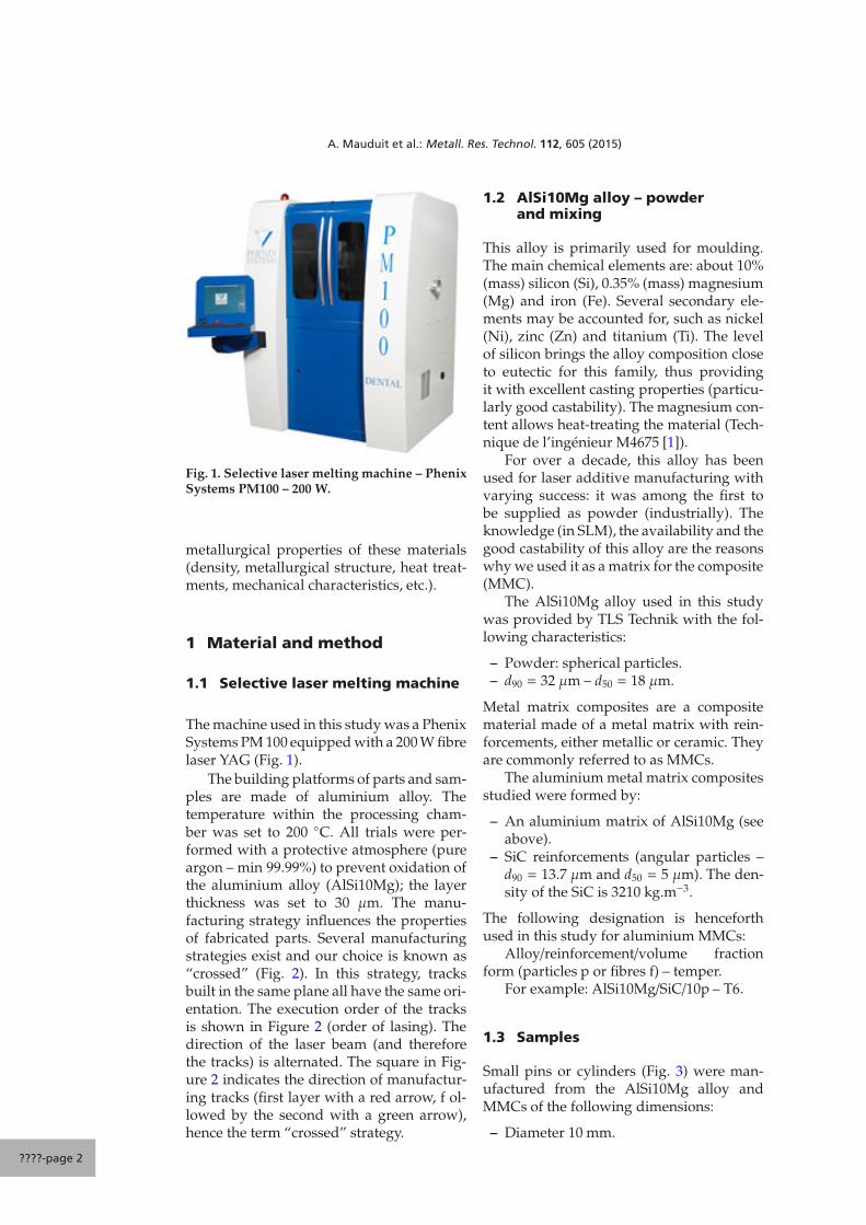
The machine used in this study was a PhenixSystems PM 100 equipped with a 200 W fibrelaser YAG (Fig. 1).
The building platforms of parts and sam-ples are made of aluminium alloy. Thetemperature within the processing cham-ber was set to 200 ◦C. All trials were per-formed with a protective atmosphere (pureargon – min 99.99%) to prevent oxidation ofthe aluminium alloy (AlSi10Mg); the layerthickness was set to 30 μm. The manu-facturing strategy influences the propertiesof fabricated parts. Several manufacturingstrategies exist and our choice is known as“crossed” (Fig. 2). In this strategy, tracksbuilt in the same plane all have the same ori-entation. The execution order of the tracksis shown in Figure 2 (order of lasing). Thedirection of the laser beam (and thereforethe tracks) is alternated. The square in Fig-ure 2 indicates the direction of manufactur-ing tracks (first layer with a red arrow, f ol-lowed by the second with a green arrow),hence the term “crossed” strategy.
1.2 AlSi10Mg alloy – powderand mixing
This alloy is primarily used for moulding.The main chemical elements are: about 10%(mass) silicon (Si), 0.35% (mass) magnesium(Mg) and iron (Fe). Several secondary ele-ments may be accounted for, such as nickel(Ni), zinc (Zn) and titanium (Ti). The levelof silicon brings the alloy composition closeto eutectic for this family, thus providingit with excellent casting properties (particu-larly good castability). The magnesium con-tent allows heat-treating the material (Tech-nique de l’ingénieur M4675 [1]).
For over a decade, this alloy has beenused for laser additive manufacturing withvarying success: it was among the first tobe supplied as powder (industrially). Theknowledge (in SLM), the availability and thegood castability of this alloy are the reasonswhy we used it as a matrix for the composite(MMC).
The AlSi10Mg alloy used in this studywas provided by TLS Technik with the fol-lowing characteristics:
Metal matrix composites are a compositematerial made of a metal matrix with rein-forcements, either metallic or ceramic. Theyare commonly referred to as MMCs.
The aluminium metal matrix compositesstudied were formed by:
– An aluminium matrix of AlSi10Mg (seeabove).
– SiC reinforcements (angular particles –d90 = 13.7 μm and d50 = 5 μm). The den-sity of the SiC is 3210 kg.m−3.
The following designation is henceforthused in this study for aluminium MMCs:
Alloy/reinforcement/volume fractionform (particles p or fibres f) – temper.
For example: AlSi10Mg/SiC/10p – T6.
1.3 Samples
Small pins or cylinders (Fig. 3) were man-ufactured from the AlSi10Mg alloy andMMCs of the following dimensions:
– Diameter 10 mm.
????-page 2
A. Mauduit et al.: Metall. Res. Technol. 112, 605 (2015)
6
3
5
2
4
1
1 4 2 5 3 6 Order of lasing
x
y
z
z
x y
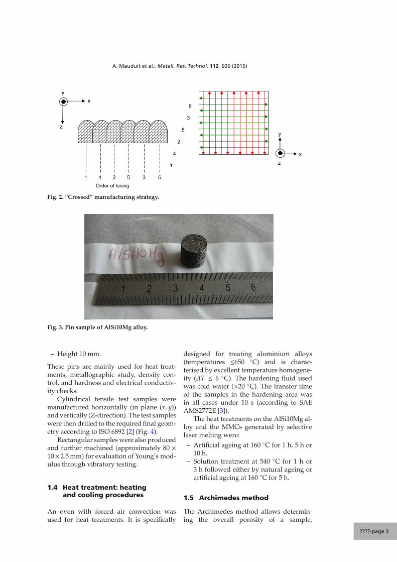
Fig. 2. “Crossed” manufacturing strategy.
Fig. 3. Pin sample of AlSi10Mg alloy.
– Height 10 mm.
These pins are mainly used for heat treat-ments, metallographic study, density con-trol, and hardness and electrical conductiv-ity checks.
Cylindrical tensile test samples weremanufactured horizontally (in plane (x, y))and vertically (Z-direction). The test sampleswere then drilled to the required final geom-etry according to ISO 6892 [2] (Fig. 4).
Rectangular samples were also producedand further machined (approximately 80 ×10× 2.5 mm) for evaluation of Young’s mod-ulus through vibratory testing.
1.4 Heat treatment: heatingand cooling procedures
An oven with forced air convection wasused for heat treatments. It is specifically
designed for treating aluminium alloys(temperatures ≤650 ◦C) and is charac-terised by excellent temperature homogene-ity (ΔT ≤ 6 ◦C). The hardening fluid usedwas cold water (≈20 ◦C). The transfer timeof the samples in the hardening area wasin all cases under 10 s (according to SAEAMS2772E [3]).
The heat treatments on the AlSi10Mg al-loy and the MMCs generated by selectivelaser melting were:
– Artificial ageing at 160 ◦C for 1 h, 5 h or10 h.
– Solution treatment at 540 ◦C for 1 h or3 h followed either by natural ageing orartificial ageing at 160 ◦C for 5 h.
1.5 Archimedes method
The Archimedes method allows determin-ing the overall porosity of a sample,
????-page 3
A. Mauduit et al.: Metall. Res. Technol. 112, 605 (2015)
Fig. 4. Cylindrical samples (length = 60 mm – diameter = 10 mm) and reduced tensile samples
(L0 = 5.65√
S0 = 25 mm with S0 cross-section).
differentiating the open porosity Po from theclosed porosity Pf. This method is often usedto determine the density of parts and sam-ples made by SLM [4].
The principle is to measure mass m1 inair and mass m3 in liquid, to which we adda measurement in air of mass m2 of the sam-ple, which has been impregnated with thewetting fluid (distilled water).
Let m1 be the dry sample mass in air (g).Let m2 be the wet sample mass in air (g).Let m3 be the immersed sample mass inwater (g).Let ρliq be the water density.Let ρth be the theoretical density of theevaluated material.Po and Pf may be expressed (in %) asfollows:
Po =m2 −m1
m2 −m3× 100 (1)
P f =m1
(1 − ρliq
ρth
)−m3
m2 −m3× 100 (2)
1.6 Mechanical tests (tensile testing)
Tensile testing trials were conducted at am-bient temperature and at 180 ◦C, pursuantto NF EN ISO 6892-1 and -2 [2] on a 100 kNW&B LFM machine (accuracy class 0.5 –range 1–100 kN). The tensile test speed usedwas 5 mm.min−1.
1.7 Vibratory tests (Young’sModulus E)
Vibratory tests were performed to determinethe Young’s modulus of the studied materi-als. They are based on the resonance of a uni-form beam in planar flexion. Vibratory eval-uation consists of applying a known stress tothe beam, then measuring its response. Sim-ple geometrical constructions such as beams
(Sect. 2.3) are used with known boundaryconditions. Under these conditions, it is pos-sible to extract a value for E (Young’s mod-ulus) from the natural frequency.
For a beam of rectangular cross-section, the equation is given by (Oberst’smethod [5]):
E =μ
I
(2π f i L2
Ai
)2
(3)
with:
– E: Young’s modulus;– i: the subscript referring to the modal
number of the vibratory mode (here i = 1,the first mode of vibration);
– f i: the natural frequency for said modein Hz (here f1);
– L: the beam length in m;– μ: the linear mass of the beam in kg.m−1;– I: moment of inertia in m4;– Ai: a coefficient related to the vibratory
mode and the boundary conditions (hereA1: free-free – first mode of vibration=> A1 = 22.4).
1.8 Hardness and electricalconductivity trials
These tests were conducted at ambient tem-perature such that:
– For Brinell hardness and Vickers micro-hardness: Struers Duramin 500/A300 ma-chines (according to NF EN ISO 6506-1 [6] and 6507-1 [7]) were used. Aminimum of three measurements persample were performed.
– For electrical conductivity: a Fischer-scope MMS device (without temperatureadjustment) was used. Trials were per-formed at 21 ± 2 ◦C, with a minimum ofthree measurements per sample.
????-page 4
A. Mauduit et al.: Metall. Res. Technol. 112, 605 (2015)
Measurement: m1 m 2 m 3
Precision balance
Closed porosity
Open pososity
We�ng fluid
Fig. 5. Basis of the Archimedes method.
Table 1. Manufacturing parameters.
Alloys Power Speed Coverage indicator Compacting indicator(W) (mm.s−1) (%) (%)
Samples for micrographic evaluation wereconventionally prepared (cutting, mount-ing, polishing, micrographic etching, etc.)prior to observation under an optical mi-croscope Zeiss Axio imager M2m. For in-formation purposes, two types of etchingwere used: reagent with sulphuric acid (10%H2SO4 and 5% HF) and Barker’s reagent(electrolytic etching with processing param-eters: 30 V – 1 min).
Similarly, samples for Scanning Elec-tron Microscopy (SEM) were prepared inthe usual fashion and observed under aSEM Zeiss EVD. The latter is equippedwith an EDS (Energy Dispersive X-ray Spec-troscopy) sensor.
2 Results and discussion
2.1 Preliminary results
The objective was to determine an optimumSLM processing window for the AlSi10Mgalloy and the corresponding MMCs.
Three main processing parameters (fac-tors for a DOE) were selected:
– the laser scan velocity, noted V;– the recovery rate between two beam
paths, Tr which is directly related to thescan spacing, Ev (the scan spacing be-ing the distance between two consecutivelaser beams);
– and the compacting indicator Tc (thecompacting indicator being the percent-age of the layer thickness deposited inexcess of said thickness, e.g. a Tc of 50%for a layer of 30 μm gives a thickness ofdeposited powder of 45 μm).
Too low or too high values for these factorslead to decreased densification, and hencepoor mechanical properties of the manufac-tured components.
We could use a Box Behnken experimen-tal design (DOE) to meet our needs: oneDOE per material. The output of this DOEis the closed porosity using the Archimedesmethod. The open porosity was not kept as aselection criterion, given the high measure-ment uncertainties related to the mass eval-uation of water-impregnated samples.
Table 1 summarises the main parame-ters of interest for manufacturing of samplesin AlSi10Mg alloy and the various MMCsstudied.
????-page 5
A. Mauduit et al.: Metall. Res. Technol. 112, 605 (2015)
Fig. 6. Pin sample cracking (AlSi10Mg/SiC/15p – as built).
The volume fraction of SiC in the MMCspresented here is limited to 15%. Indeed, us-able samples (even pins) are harder to obtainfor higher fractions. As shown in Figure 6,the samples are cracked; this phenomenonis enhanced with increased SiC volume frac-tions. Cracking is possibly due to inter-nal stresses induced by the manufacturingmethod.
2.2 Characterisation
2.2.1 Sample density
Note that the theoretical density forAlSi10Mg alloy, based on the chemicalcomposition of the material batch used(see Sect. 2.2.2, Table 2) for the study is2654 kg.m−3.
The pins retained for the study have adensity ranging from 2630 to 2650 kg.m−3,i.e. very close to the theoretical volume massof the AlSi10Mg alloy batch studied. On av-erage, the density of the samples made ofAlSi10Mg alloy is 2641 kg.m−3.
From Figure 7a, it is clear that despite theinclusion of SiC reinforcements and a higher
density than aluminium, the composite den-sities remain lower than that of the alloyalone. This is simply due to increased poros-ity. The insertion of reinforcements into analuminium metal matrix is therefore gener-ally detrimental to porosity.
Nevertheless, the composites densitygrows linearly with the reinforcements (SiC)volume fraction, as per Figure 7b. Since thismeasured curve is not parallel to its theo-retical counterpart (magenta line on Fig. 7a),it appears there is a linear relationship be-tween the porosity and reinforcements vol-ume fraction.
2.2.2 Chemical analysis
Chemical analysis following the ICP-AESmethod was conducted on the AlSi10Mgpowder supplied by TLS Technik (Table 2).It appears the chemical compound Mg isabove the tolerance limits: 0.75% (mass) in-stead of 0.45% (mass) for the standard com-position of AlSi10Mg (according to NF EN1706 [8]). A second analysis was performed(Table 2) on a “pin” sample of AlSi10Mgmanufactured using SLM (see Sect. 1.3).
????-page 6
A. Mauduit et al.: Metall. Res. Technol. 112, 605 (2015)
a
b
Linear (MMC
Linear (Theoretical)
Fig. 7. (a) Average density related to the reinforcement volume fraction. (b) Composites average density model.
Table 2. Chemical analysis (Wt%) of the powder and a AlSi10Mg alloy pin made by selective lasermelting.
AlSi10Mg Si Fe Cu Mn Mg Cr Ni Zn TiPowder 10.1 0.19 <0.005 <0.005 0.75 0.007 0.009 0.008 0.014
A. Mauduit et al.: Metall. Res. Technol. 112, 605 (2015)
Laser beam
Track r
Fig. 8. Simplified modelling of a track.
The results show the compound Mg hasdecreased to 0.32% (mass), which is fullycompliant with the standard composition ofAlSi10Mg.
Thus, there is a 0.43% loss of Mg. Thelatter has the lowest vaporisation tempera-ture (1090 ◦C) amongst all other compoundspresent; it is thus possible that part of themagnesium vaporised during the laser fu-sion process. This phenomenon was also ob-served at the LERMPS laboratory [9]. Pow-ders are thus supplied with an increasedquantity of magnesium to ensure the con-formity (according to NF EN 1706 [8]) of thealloy after selective laser melting.
According to Tissot [10], with a simplemodelling of a track with a hemisphericalmelt (Fig. 8) which is quite close to real-ity (see Fig. 22), it is possible to determinethe theoretical maximum temperature dif-ference in the track from Equation (4):
ΔT =q
2λπ r(4)
with:
q: power passing through the surface ofthe melt bath. q = 40 W, allowing thepower transmitted to the track to be 20%(estimation) of the laser power (200 W);this is due to the high reflectivity of thealuminium alloy [11].λ: thermal conductivity of theAlSi10Mg alloy made by SLM.λ = 103 W.m−1.◦C−1 [12].r: mean radius of the track. r = 78 μmbecause the average width of the trackswas evaluated as being 156 μm in theDOE.
Thus, under these conditions, an evaluationofΔT is 792 ◦C. Assuming that the contour ofthe track is 600 ◦C (the liquidus temperaturefor this AlSi10Mg alloy), then the maximum
temperature at the centre of the laser beamis 1392 ◦C, which is greater than 1090 ◦Cmagnesium evaporation.
2.2.3 Hardness and electricalconductivity
Figure 9 below shows the evolution of micro-hardness HV0.3 and hardness HBW 1/10with respect to the artificial ageing dura-tion: base (no tempering, 0 h), 1 h of arti-ficial ageing at 160 ◦C, 5 h of artificial age-ing at 160 ◦C and 10 h of artificial ageingat 160 ◦C for the AlSi10Mg alloy. Both thesehardnesses (micro/macro) are used to eval-uate the potential influence of porosity onhardness measurements.
There are no notable differences in the be-haviour of either hardness: conclusions willthus be identical for both. As such, only theHBW 1/10 results will be discussed hereafter.Artificial ageing has little influence on theas-built temper, regardless of the hardness.The slight decrease in the alloy hardness af-ter artificial ageing for 10 h at 160 ◦C is mostprobably related to the higher porosity of thesample pin (0.7% against 0.1% closed poros-ity for all other pins) rather than evidence ofthe influence of the artificial ageing.
Figure 10 describes the influence of con-ventional heat treatments, i.e. solution heattreatment, quenching, and natural or artifi-cial ageing, so as to obtain temper T4 and T6,on the HBW 1/10 hardness of pins manufac-tured by selective laser melting (AlSi10Mgalloy and MMCs).
All hardness values (for all natural andartificial ageing cases) are lower than thoseobtained from as built temper. As expected,the hardness of T4 is lower than that of T6.
The values obtained in this study werealso compared with normalising valuesfound in the literature, as given in Table 3.
????-page 8
A. Mauduit et al.: Metall. Res. Technol. 112, 605 (2015)
50
70
90
110
130
150
170
190
0 2 4 6 8 10 12
Ageing time (hours)
Har
dnes
s H
V0,3
50
70
90
110
130
150
170
190
Har
dnes
s H
BW
1/1
0
Hardness HV0,3Hardness HBW 1/10
Fig. 9. Micro-hardness HV0.3 and hardness HBW 1/10 depending on the artificial ageing duration(160 ◦C).
Fig. 10. Influence of the solution heat-treatment time on natural and artificial ageing (AlSi10Mgalloy and MMCs).Note: natural ageing for at least 4 days, artificial ageing for 5 h at 160 ◦C.
Table 3. Hardness values of AlSi10Mg alloy and MMC depending on temper.
Alloys Hardness HBW SourcesAlSi10Mg (SLM) T6 95 (approximately) In this study
AlSi10Mg KT6 90 mini Table 2 – NF EN 1706 [8]A-S10G Y33 95 (typical) Aluminium Pechiney [13]
AlSi10Mg/SiC/10p-T6 140 (approximately) In this studyF3S.10S T6 128 (typical) Duralcan composites [15]
????-page 9
A. Mauduit et al.: Metall. Res. Technol. 112, 605 (2015)
It is clear that the hardness of AlSi10MgT6 alloy obtained from selective laser melt-ing meets NF EN 1706, corresponding ex-actly to the data given by AluminiumPechiney [13]. There is thus no improvementin the mechanical characteristics under suchconditions.
At as-built temper, AlSi10Mg alloy frompowder-bed fusion exhibits particularlyhigh hardness values: much higher thanboth the temper F and T6 states given by NFEN 1706 [8]. It is also 30 HV above the val-ues given by Kempen et al. [14] for a similarmanufacturing technique.
AlSi10Mg/SiC/10p-T6 MMC from selec-tive laser melting thus has a higher hard-ness than an equivalent commercial alloysuch as F3S.10S T6 [15]. The hardness of theAlSi10Mg/SiC/10p-T6 is therefore improvedby about 9–10%.
The electrical conductivity is often usedto monitor the precipitation of an aluminiumalloy.
Variations in the electrical conductivityof the AlSi10Mg alloy (from selective lasermelting) were also monitored in relation tothe artificial ageing duration (similarly to thehardness, as presented previously) (Fig. 11).
Electrical conductivity increases with ar-tificial ageing time, implying an evolutionof the alloy precipitation, and thus a modifi-cation of the mechanical properties. How-ever, no changes in hardness were noted(Fig. 9). As such, despite a modificationof the alloy precipitation, the latter doesnot seem to significantly influence as-builttemper hardness.
Figure 12 shows the electrical conductiv-ity in relation to various tempers; consid-ering the conventional metallurgy of alu-minium alloys, temper T4 exhibits lowerelectrical conductivity (along with a lowerhardness) than T6. Note the electrical con-ductivity for a 3 h solution heat treatmentis slightly under that for a 1 h one, regard-less of the subsequent treatment stage (nat-ural or artificial ageing). This is possibly dueto a more efficient solution heat treatmentfor a 3 h long operation: more precipitatesdissolve into the solid aluminium solution.However, if this difference exists, it has nosignificant effect on the hardness values.
Table 4. Young’s modulus, E (AlSi10Mg alloy).
Sample No. Density (kg.m−3 ) E Modulus (MPa)1 25 57 66 7042 25 62 66 4243 25 63 65 807
Average 66 312Standard deviation 459
Table 5. Comparison of Young’s modulus(AlSi10Mg alloy).
Alloy E modulus (GPa) SourcesAlSi10Mg-A359.0 72 [16]
Gravity permanentmould casting
AlSi10Mg 68 ± 3 [14]SLM
AlSi10Mg 66.3 ± 0.5 In this studySLM
2.2.4 Mechanical characteristics
2.2.4.1 Young’s modulus
For these trials, three samples as per Sec-tion 1.3 were used. Table 4 presents the mea-sured E-modulus, according to Equation (3).
The selected value for Young’s modu-lus for AlSi10Mg alloy (from selective lasermelting) is 66.3 ± 0.5 GPa. Comparison wasmade with values found in the literature, aspresented in Table 5.
The measured value is 8% lower thanthat conventionally accepted in gravity per-manent mould casting; however, comparedwith values obtained from a similar produc-tion method, the gap is smaller but still re-mains lower [14].
We also established Young’s modulusfor the AlSi10Mg/SiC/5p composite. Of allthree samples available for this material,only one was retained; the others were toosmall and/or of too low density.
For the AlSi10Mg/SiC/5p MMC (from se-lective laser melting) the value for Young’smodulus retained is 77.3 GPa. Young’s mod-ulus is therefore increased by approximately16.5% compared with the AlSi10Mg alloy.
According to Totten [17], the rule ofmixtures or the iso-deformation criteria aregiven by Equation (5) and the iso-stress cri-teria are given by Equation (6).
Ecd = Vm Em+ Vp Ep
(iso-deformation criteria) (5)
????-page 10
A. Mauduit et al.: Metall. Res. Technol. 112, 605 (2015)
12
13
14
15
16
17
18
19
0 2 4 6 8 10 12
Ageing time (hours)
elec
tric
al c
ondu
ctiv
ity (M
S/m
)
Fig. 11. Electrical conductivity depending on artificial ageing time (AlSi10Mg alloy).
0
5
10
15
20
25
As build SHT 1h SHT 3h SHT 1h SHT 3h
Elec
tric
al c
ondu
ctiv
ity (e
n M
S/m
)
Natural ageing (T4) Artificial ageing (T6)
As built
Fig. 12. Electrical conductivity depending on temper (AlSi10Mg alloy).
with:
– Ecd or Ecs (see Eq. (6)) the elasticity mod-ulus for the composite;
– Em the elasticity modulus for the matrix;– Ep the elasticity modulus for the particle
reinforcement;– Vm the matrix volume fraction;– Vp the particle reinforcement volume
fraction.
Ecs =1
VmEm+
VpEp
(iso-stress criteria) (6)
According to the literature [17], MMCs donot conform with the iso-deformation andiso-stress criteria. Indeed, aluminium alloyMMCs are between two laws: the iso-stresscriteria being the lower limit and the iso-deformation criteria being the upper limit.
????-page 11
A. Mauduit et al.: Metall. Res. Technol. 112, 605 (2015)
0
50
100
150
200
250
300
350
400
450
500
0 0,5 1 1,5 2 2,5 3
Elongation (%)
Stre
ss (M
Pa)
XY directionXZ direction
Fig. 13. Conventional tensile curves for AlSi10Mg alloy (as built) by selective laser melting.
Table 6. Conventional mechanical characteristics of AlSi10Mg alloy (SLM).
AlSi10Mg (as built)Orientation Temperature Rm (MPa) Rp0.2 (MPa) A (%)
Table 6 presents the mechanical propertiesof horizontally and vertically built tensile
test samples for as-built AlSi10Mg andAlSi10Mg T6 material.
The as-built temper mechanical charac-teristics are systematically better, as previ-ously suggested by the hardness measure-ments conducted. As expected, mechanicalcharacteristics at 180 ◦C are lower than atambient temperature. There is also a stronganisotropy of these characteristics, the latterbeing always higher in the (x, y) plane thanin the Z direction, as shown in Figure 13.
Conversely, the paper from Kempenet al. [14] does not give any evidence ofanisotropy, despite using the same produc-tion strategy for the alloy (Fig. 3 in Ref. [14]).
????-page 12
A. Mauduit et al.: Metall. Res. Technol. 112, 605 (2015)
In the same paper, the mechanical character-istics (Rm) in plane (x, y) are 12% lower thanthe ones presented here.
2.2.5 Metallographic study
2.2.5.1 Construction strategy
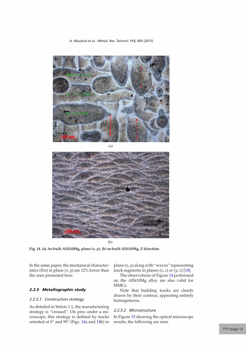
As detailed in Setion 1.1, the manufacturingstrategy is “crossed”. On pins under a mi-croscope, this strategy is defined by tracksoriented at 0◦ and 90◦ (Figs. 14a and 14b) in
plane (x, y) along with “waves” representingtrack segments in planes (x, z) or (y, z) [18].
The observations of Figure 14 performedon the AlSi10Mg alloy are also valid forMMCs.
Note that building tracks are clearlydrawn by their contour, appearing entirelyhomogeneous.
2.2.5.2 Microstructure
In Figure 15 showing the optical microscoperesults, the following are seen.
????-page 13
A. Mauduit et al.: Metall. Res. Technol. 112, 605 (2015)
Particles of SiC
Eutectic acicular compound Al-Si
0%
5%
10%
15%
Fig. 15. Microscopic results without and with etching (reagent with sulphuric acid) of: 0%AlSi10Mg/SiC/0p – 5% AlSi10Mg/SiC/5p – 10% AlSi10Mg/SiC/10p – 15% AlSi10Mg/SiC/15p (noetching).
The microstructure of all the materials(Fig. 15) is made of dendrites (more or lessfine) of solid aluminium solution along withacicular Al-Si eutectics. Nevertheless the mi-crostructure rapidly evolves: an increase inthe reinforcements (SiC) volume fractionmodifies the latter to a “coarser” one. It is
then characterised by the increased presenceof acicular components (mainly Al-Si eutec-tics) with the increase in the reinforcementvolume fraction.
The grains are not revealed here. Onlyelectrolytic etching can reveal them. We willsee that they have a size of a few tens of
????-page 14
A. Mauduit et al.: Metall. Res. Technol. 112, 605 (2015)
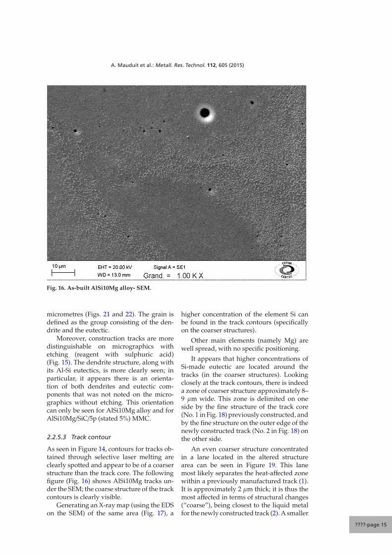
Fig. 16. As-built AlSi10Mg alloy- SEM.
micrometres (Figs. 21 and 22). The grain isdefined as the group consisting of the den-drite and the eutectic.
Moreover, construction tracks are moredistinguishable on micrographics withetching (reagent with sulphuric acid)(Fig. 15). The dendrite structure, along withits Al-Si eutectics, is more clearly seen; inparticular, it appears there is an orienta-tion of both dendrites and eutectic com-ponents that was not noted on the micro-graphics without etching. This orientationcan only be seen for AlSi10Mg alloy and forAlSi10Mg/SiC/5p (stated 5%) MMC.
2.2.5.3 Track contour
As seen in Figure 14, contours for tracks ob-tained through selective laser melting areclearly spotted and appear to be of a coarserstructure than the track core. The followingfigure (Fig. 16) shows AlSi10Mg tracks un-der the SEM; the coarse structure of the trackcontours is clearly visible.
Generating an X-ray map (using the EDSon the SEM) of the same area (Fig. 17), a
higher concentration of the element Si canbe found in the track contours (specificallyon the coarser structures).
Other main elements (namely Mg) arewell spread, with no specific positioning.
It appears that higher concentrations ofSi-made eutectic are located around thetracks (in the coarser structures). Lookingclosely at the track contours, there is indeeda zone of coarser structure approximately 8–9 μm wide. This zone is delimited on oneside by the fine structure of the track core(No. 1 in Fig. 18) previously constructed, andby the fine structure on the outer edge of thenewly constructed track (No. 2 in Fig. 18) onthe other side.
An even coarser structure concentratedin a lane located in the altered structurearea can be seen in Figure 19. This lanemost likely separates the heat-affected zonewithin a previously manufactured track (1).It is approximately 2 μm thick; it is thus themost affected in terms of structural changes(“coarse”), being closest to the liquid metalfor the newly constructed track (2). A smaller
????-page 15
A. Mauduit et al.: Metall. Res. Technol. 112, 605 (2015)
Fig. 17. Element Si (white) evidences.
1
2
Fig. 18. Building track contour.
“disturbed” area is also found in the newtrack, which may be caused by several fac-tors: a dough-like area, modified coolingrate, etc.
2.2.5.4 Grain size and DAS (AlSi10Mg alloy)
The DAS (dendrite arm spacing) is the dis-tance between secondary arms and den-drites (of aluminium alloy solid solution). In
recent years, DAS has been used to describethe metallurgical structure of cast alloysand to estimate their mechanical character-istics [1]. In Figure 20, fine dendrites of solidaluminium solution along with Al-Si eutec-tics are observed. The DAS for the AlSi10Mgalloy is evaluated at 0.5–0.6 μm (Table 7 andFig. 20) with the intercept method [19].
These observations confirm thatthe structure obtained by additive
????-page 16
A. Mauduit et al.: Metall. Res. Technol. 112, 605 (2015)
2
1 HAZ within a track previously manufactured (1)
Disturbed area in the new track (2)
Fig. 19. Details of a building track contour: HAZ and disturbed area.
1
2
3
4
5
Fig. 20. Practical application of the intercept method – AlSi10Mg alloy (example).
????-page 17
A. Mauduit et al.: Metall. Res. Technol. 112, 605 (2015)
Table 7. DAS measurement.
Line Number of Line length DAS(Fig. 20) dendrite intercepted (μm) (μm)
manufacturing (selective laser melting)is rather fine. Indeed, the DAS for goodquality gravity permanent mould casting isof the order of 20 μm [19].
The Hall-Petch [20] law relates the DASsize to the mechanical characteristics (yieldstrength Rp0.2) as follows:
Rp0.2 = A +K√DAS
(7)
A hardening effect (increase in the yieldstrength)ΔRp0.2 can be expressed as in Equa-tion (8); hardening is obtained by the den-drites refinement, for which the mean DASvalue goes from DAS1 to DAS2 (DAS1 <DAS2):
ΔRp0.2 = K(
1√DAS2
− 1√DAS1
)(8)
The coefficient K is dependent on the metal,more specifically its crystalline system; assuch, the ΔRp0.2 is in MPa, the DAS in mmand K is of the order of 8 for aluminiumalloys [23].
Thus, going from DAS1 = 20 μm toDAS2 = 0.5−0.6 μm, the hardening is valuedat 270 MPa. Referring to the expected yieldstrength of AlSi10Mg alloy from gravity per-manent mould casting in temper F (e.g. 100–110 MPa) and the yield strength obtainedfrom selective laser melting, in as-built sam-ples (e.g. 365 MPa, see Sect. 2.2.4.2, Table 6),the value found is ΔRp0.2 = 260 MPa (ap-proximately). The Hall-Petch relation thusappears to clarify the increase in mechani-cal properties generated from selective lasermelting.
The microstructure size obtained is de-pendent on the cooling rate ν. The followingrelation is often found in reference [23]:
λ = Bv−n (9)
with:
– λ the formed grain size (or distance be-tween dendrite arms);
– B and n constants, dependent on the alloyconsidered.
For Al-Si alloys λ is assimilated to the DASin Equation (9), thus giving:
DAS =B3√
v(10)
Thus
v =( B
DAS
)3
(11)
Taking B = 35, n = 1/3 and DAS =0.6 μm [23], the cooling speed is200 000 ◦C.s−1, which corresponds tothe admissible cooling speed for selectivelaser melting [24].
Another technique to assess the coolingrate is the resolution of the heat equation inthree-dimensional space (x, y, z). Only onenumerical solution of the equation that wehave not implemented here is conceivable.
The following figure (Figs. 21a and 21b)shows alloy grains located inside buildingtracks on an (x, z) and (x, y) cut.
The grains are oriented along Z withthe tracks; there is thus a strong grainsize anisotropy in the Z direction in the(x, y) plane. Indeed, grain size ranges from1 to 10 μm in plane (x, y) whilst rangingfrom 17 to 42 μm along Z. As before, thisyield strength anisotropy (between plane(x, y) and the Z direction) may be explainedthrough the Hall-Petch law. Replacing theDAS by the grain size (mean diameter) gives:
ΔRp0.2 = K(
1√d2− 1√
d1
)(12)
with d2 ≈ 5 μm and d1 ≈ 30 μm, the valuefound is ΔRp0.2 = 67 MPa (approximately).In this study, ΔRp0.2 (anisotropy) ≈62 MPa,thus showing the accuracy of the Hall-Petchlaw.
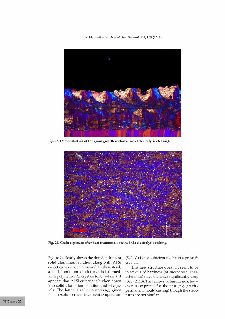
The following figure (Fig. 22) shows thegrain orientation within the track into a cut(x, z). It appears that the grains grow from theedges of the bead in contact with other build-ing tracks to the outer surface of the bead (incontact with argon): this is simply due toa directional solidification: faster cooling atthe surface of already consolidated material.
????-page 18
A. Mauduit et al.: Metall. Res. Technol. 112, 605 (2015)
Construction direction
a
(a)
y
x
b
(b)
Fig. 21. (a) Grain exposure in tracks via electrolytic etching: plane (x, z), (b) grain exposure in tracksvia electrolytic etching: plane (x, y).
Note also in Figure 22, the almost identi-cal grain orientation within manufacturingtracks.
When performing a solution treatment-quenching-artificial ageing (say for temper
T6 – see Sect. 1.4) on as-built AlSi10Mg pinsmade by selective laser melting, the alloystructure is modified. Comparing Figures 21(as built) and 23 (after heat treatments):
– The suppression of building tracks [21].– A more random grain orientation [21].– A grain size ranging from 16 to 42 μm.
????-page 19
A. Mauduit et al.: Metall. Res. Technol. 112, 605 (2015)
Fig. 22. Demonstration of the grain growth within a track (electrolytic etching).
y
x
Fig. 23. Grain exposure after heat treatment, obtained via electrolytic etching.
Figure 24 clearly shows the thin dendrites ofsolid aluminium solution along with Al-Sieutectics have been removed. In their stead,a solid aluminium solution matrix is formed,with polyhedron Si crystals (of 0.5–4 μm). Itappears that Al-Si eutectic is broken downinto solid aluminium solution and Si crys-tals. The latter is rather surprising, giventhat the solution heat-treatment temperature
(540 ◦C) is not sufficient to obtain a priori Sicrystals.
This new structure does not seem to bein favour of hardness (or mechanical char-acteristics) since the latter significantly drop(Sect. 2.2.3). The temper T6 hardness is, how-ever, as expected for the cast (e.g. gravitypermanent mould casting) though the struc-tures are not similar.
????-page 20
A. Mauduit et al.: Metall. Res. Technol. 112, 605 (2015)
Fig. 25. Optical microscope and SEM observation of Al-Si-Fe precipitates.
Additionally, along with the structuralchanges previously revealed (also found inFig. 25), Al-Si-Fe precipitates also appeared(possibly FeSiAl5 plates).
These precipitates are not found in theas-built samples (selective laser melting). Itis possible that these precipitates are dis-solved (in the solid aluminium solution) athigher temperatures (beyond the solutionheat-treatment temperature), and thus not
precipitating because of the high coolingspeed.
3 Conclusion
The study of additive processing ofAlSi10Mg aluminium alloy and MMCs ob-tained from selective laser melting shows:
– The difficulty of manufacturing MMCsamples from 15% (in volume) SiC
????-page 21
A. Mauduit et al.: Metall. Res. Technol. 112, 605 (2015)
reinforcements, probably due to residualstresses.
– The temperature reached by the laserbeam appears to cause vaporisation ofmetals with low evaporation point, suchas magnesium (or zinc in other alu-minium alloys).
– When the volume fraction of SiC rein-forcements increases, there is an evolu-tion of the microstructure, with the ap-pearance of acicular components.
– Higher mechanical properties for the as-built temper, associated with F (as man-ufactured) or T1 according to the nor-malization in place (i.e. cooled after heattransformation and natural ageing untilstabilised).
– Significant increase in the conventionalmechanical properties compared withcasting, due to hardening by structurerefinement. This effect can be describedby the Hall-Petch law, and is linked toa rapid cooling rate of approximately200 000 ◦C/s.
– Surprising changes in the alloy metal-lurgical structure caused by the heattreatments (solution treating-quenching-artificial ageing): a solid aluminium so-lution matrix with polyhedron Si crys-tals and Al-Si-Fe precipitates (possiblyFeSiAl5 plates).
Acknowledgements
The authors would like to thank the CETIM (Cen-tre Technique des Industries de la Mécanique) forthe financing and support provided for this study.
References
[1] Technique de l’ingénieur M4675,JACOB Sylvain, Propriétés des alliagesd’aluminium de fonderie
[2] norme NF EN ISO 6892-1 et -2, Matériauxmétalliques – Essais de traction – Partie1: méthode d’essai à température ambiante– Partie 2: Méthode d’essai à températureélevée
[3] standard SAE aerospace AMS2772E, Heattreatment of aluminum alloy raw materials
[4] A.B. Spierings, M. Schneider, R.Eggenberger, Rapid Prototyping J. 17(2011) 380-386
[5] A. Renault, Caractérisation mécaniquedynamique de matériaux poro-visco-élastiques, Thèse de doctorat, Universitéde Sherbrooke, département de géniemécanique, 2008, 149 p.
[6] norme NF EN ISO 6506, Matériaux mé-talliques – Essai de dureté Brinell
[7] norme NF EN ISO 6507, Matériaux mé-talliques – Essai de dureté Vickers
[8] norme NF EN 1706, Aluminium et al-liages d’aluminium – Pièces moulées –Composition chimique et caractéristiquesmécaniques
[9] L. Dembinski, Enjeux industriels en mé-canique : de l’impression 3D à la fusion laser,Principe et élaboration de poudre par atom-isation gazeuse, granulométrie et traçabilitépour la fabrication additive, Rendez voustechnologique du CETIM-CERTEC, octobre2013
[10] F.X. Tissot, Étude phénoménologique etmodélisation du comportement du bain defusion en soudage TIG en vue d’une applica-tion au contrôle du procédé, Rapport CEA,Saclay, 1998, 184 p.
[11] G. Tirand, Étude des conditions de soudagelaser d’alliages base aluminium par voieexpérimentale et à l’aide d’une simulationnumérique, Thèse de doctorat, École doctor-ale des sciences physiques pour l’ingénieur,Bordeaux, 2012, 131 p.
[12] EOS aluminium AlSi10Mg, Material datasheet, may 2014, 5 p
[13] Division alliages de moulage, Les al-liages d’aluminium de fonderie, AluminiumPechiney, France, 1991
[14] K. Kempen, L. Thijs, J. VaN Humbeeck, J.P.Kruth, Phys. Proc. 39 (2012) 439-436
[15] Duralcan composites for gravity casting,Property data, Alcan
[16] ASM International Handbook commitee,Aluminium and aluminium alloys, 3rd edi-tion. J.R. Davis, USA, 1996, 784 p.
[17] G. Totten, S. Mac Kenzie, Handbook ofAluminum, Marcel DEKKER, New York,2003, Vol. 2, 1296 p.
[18] K. Kempen, L. Thijs, E. Yasa, M.Bradrossamay, W. Verheecke, J.P. Kruth,Process optimization and microstructuralanalysis for selective laser melting ofAlSi10Mg
[19] B. Zhang, M. Garro, C. Tagliano, Metall. Sci.Technol. 21 (2003) 1
[20] Technique de l’ingénieur M230. CHENALBruno, DRIVER Julian, Ecrouissaged’alliages d’aluminium
????-page 22
A. Mauduit et al.: Metall. Res. Technol. 112, 605 (2015)
[22] J. Colbert Caractérisation de la fractionsolide dans les lopins semi-solides produitspar le procédé SEED, Mémoire maîtriseen ingénierie, Université du Québec,Chicoutimi, 2007, 239 p.
[23] M. Averyanova, Fusion laser de poudres mé-talliques : maîtrise du procédé pour la fabri-cation directe de pièces mécaniques, Thèsede doctorat, École nationale d’ingénieur deSaint Etienne, Saint Etienne, 2011, 236 p.
[24] E. Brandl, U. Heckenberger, V. Holzinger, D.Buchbinder, Mater. design 34 (2012) 159-169


![University of Birmingham Selective laser melting of AlSi10Mg alloy: Process … · 2018. 11. 29. · laser fabrication (DLF), and selective laser melting (SLM) [5, 6]. Aerospace manufacturers](https://static.documents.pub/doc/80x56/606f2d4d983f986eb3388e9a/university-of-birmingham-selective-laser-melting-of-alsi10mg-alloy-process-2018.jpg)


