Applications for Circulating Fluid Bed Boilers Jurgen H. Kleinau TAPPI PRESS Reprinted from 1985 Pulping Conference Book 2, October 1985 Copyright. TAPPI. Technology ParklAtlanta. GA 30348 1985
Transcript
J’
Applications for Circulating Fluid Bed Boilers
Jurgen H. Kleinau
TAPPI PRESS
Reprinted from 1985 Pulping Conference Book 2, October 1985 Copyright. TAPPI. Technology ParklAtlanta. GA 30348 1985
.-
i
APPLICATIONS FOR CIRCULATING FLUID BED BOILERS
Jurgen H. Kleinau Marketing Manager Keeler/Dorr-Oliver Boiler Company 238 West Street Williamsport, PA 17701
ABSTRACT
During the design process conventional boilers are analyzed primarily based on fuel characteristics and location of heat transfer surfaces for the chosen steam conditons. In contrast, fluid beds are solids-handling machines first and boilers second.
The paper will define fluidization as used industrially, describe circulation mechanisms and other fluidization aspects and will relate them to equipment and fuels of interest to the pulp and paper industry, with special emphasis on chemical recovery operations.
Fluid beds are more environmentally friendly by their nature than older combustion technologies. Circulating fluid beds are especially suited to control CO, SO2 and NOx emissions.
INTRODUCTION
Circulating fluid bed boilers have gained rapid acceptance in recent years. Presently operating installations and their fuels are:
Presently committed for installation are the following projects:
1985 Anthracite Culm 1985 Lignite
The pulp and paper industry has been using fluid bed combustion systems and processing systems for many years. Before these systems were given the nickname "bubbling" beds , some 20 fluid bed lime mud calciners were placed into operation since 1964. Also, since about 1966 over 30 spent pulping liquor com- bustion installations have been complet- ed. Beginning in 1969 energy-generating systems have been built using sludge and wood residues as fuel. Some were bubbling beds, but many more were high velocity or fast beds.
Outside of the pulp and paper industry there are some 60 bubbling fluid bed boilers in operation in a broad cross section of industries. Most of these boilers are coal fired,
With this proliferation of applications and terminologies one should ask why and how circulating fluid bed boilers are different and why there are applications for them in the pulp and paper industry. I
To answer these questions a closer look at fluidization is required.
FLU ID I Z AT ION
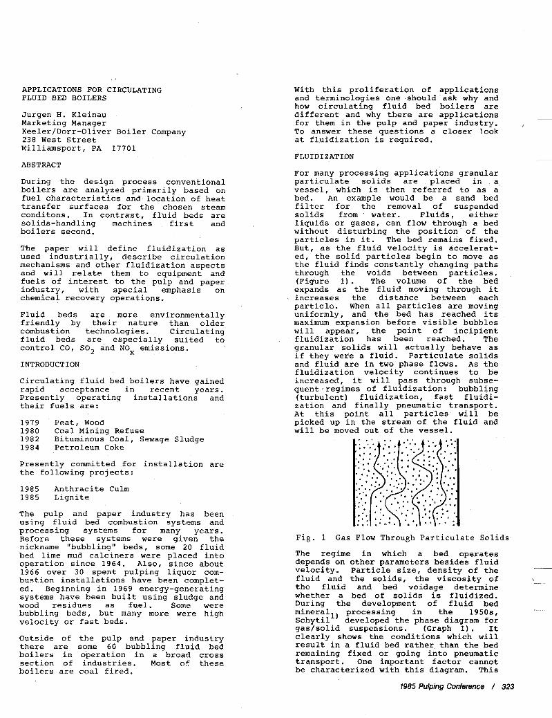
For many processing applications granular particulate solids are placed in a vessel, which is then referred to as a bed. An example would be a sand bed filter for the removal of suspended solids from water. Fluids, either liquids or gases, can flow through a bed without disturbing the position of the particles in it. The bed remains fixed. But, as the fluid velocity is accelerat- ed, the solid particles begin to move as the fluid finds constantly changing paths through the voids between particles. (Figure 1). The volume of the bed expands as the fluid moving through it
~ increases the distance between each particle. When all particles are moving uniformly, and the bed has reached its maximum expansion before visible bubbles will appear, the point of incipient
- fluidization has been reached. The granular solids will actually behave as if they were a fluid. Particulate solids and fluid are in two phase flows. As the fluidization velocity continues to be increased, it will pass through subse- quent,regimes of fluidization: bubbling (turbulent) fluidization, fast fluidi- zation and finally pneumatic transport. At this point all particles will be picked up in the stream of the fluid and will be moved out of the vessel.
* * .\ Fig. 1 Gas Flow Through Particulate Solids
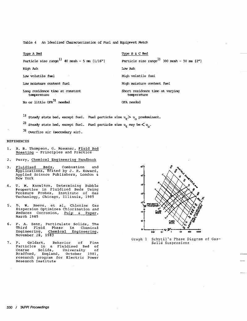
The regime in which a bed operates depends on other parameters besides fluid velocity. Particle size, density of the fluid and the solids, the viscosity of the fluid and bed voidage determine whether a bed of solids is fluidized. During the development of fluid bed mineral processing in the 1950s, Schytil') developed the phase diagram for gas/solid suspensions. (Graph 1). It clearly shows the conditions which will result in a fluid bed rather than the bed remaining fixed or going into pneumatic transport. One important factor cannot be characterized with this diagram. This
1985 Pulping Conference / 323
factor is particle shape, which must be considered separately.
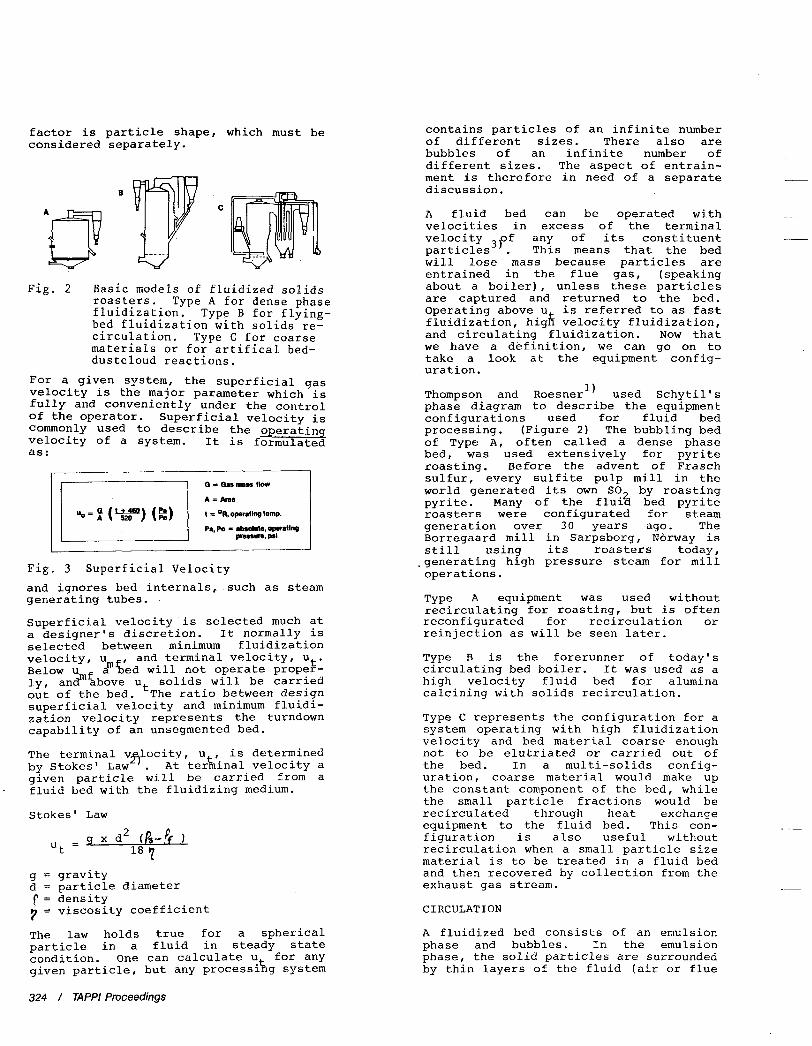
Fig. 2 Basic models of fluidized solids roasters. Type A for dense phase fluidization. Type B for flying- bed fluidization with solids re- circulation. Type C for coarse materials or for artifical bed- dustcloud reactions.
For a given system, the superficial gas velocity is the major parameter which is fully and conveniently under the control of the operator. Superficial velocity is commonly used to describe the operatin velocity of a system. It is formulate! as :
Fig. 3 Superficial Velocity and ignores bed internals, such as steam generating tubes.
Superficial velocity is selected much at a designer's discretion. It normally is selected between minimum fluidization velocity, u and terminal velocity, ut. Below umf a ged will not operate proper- ly, and above ut solids will be carried out of the bed. The ratio between design superficial velocity and minimum fluidi- zation velocity represents the turndown capability of an unsegmented bed.
The terminal v locity, u is determined by Stokes' Law . At terhhal velocity a given particle will be carried from a fluid bed with the fluidizing medium.
m
-27
Stokes' Law
x d2 (A-4 1 l8 7
Ut = 9
g = gravity d = particle diameter r = density 7 = viscosity coefficient
The law holds true for a spherical particle in a fluid in steady state condition. One can calculate ut for any given particle, but any processing system
324 / TAPPI Proceedings
contains particles of an infinite number of different sizes. There also are bubbles of an infinite number of different sizes. The aspect of entrain- ment is therefore in need of a separate discussion.
A fluid bed can be operated with velocities in excess of the terminal velocity 3,0f any of its constituent particles . This means that the bed will lose mass because particles are entrained in the flue gas, (speaking about a boiler), unless these particles are captured and returned to the bed. Operating above u is referred to as fast fluidization, high velocity fluidization, and circulating fluidization. Now that we have a definition, we can go on to take a look at the equipment config- uration.
Thompson and Roesner" used Schytil' s phase diagram to describe the equipment configurations used for fluid bed processing. (Figure 2) The bubbling bed of Type A, often called a dense phase bed, was used extensively for pyrite roasting. Before the advent of Frasch sulfur, every sulfite pulp mill in the world generated its own SO by roasting pyrite. Many of the flu& bed pyrite roasters were configurated for steam generation over 30 years ago. The Borregaard mill in Sarpsborg, Norway is still using its roasters today, .generating high pressure steam for mill operations.
Type A equipment was used without recirculating for roasting, but is often reconfigurated for recirculation or reinjection as will be seen later.
Type B is the forerunner of today's circulating bed boiler. It was used as a high velocity fluid bed for alumina calcining with solids recirculation.
Type C represents the configuration for a system operating with high fluidization velocity and bed material coarse enough not to be elutriated or carri-ed out of the bed. In a multi-solids config- uration, coarse material would make up the constant component of the bed, while the small particle fractions would be recirculated through heat exchancje equipment to the fluid bed. This con- figuration is also useful without recirculation when a small particle size material is to be treated in a fluid bed and then recovered by collection from the exhaust gas stream.
C I RCULAT I ON
A fluidized bed consists of an emulsion phase and bubbles. In the emulsion phase, the solid particles are surrounded by thin layers of the fluid (air or flue
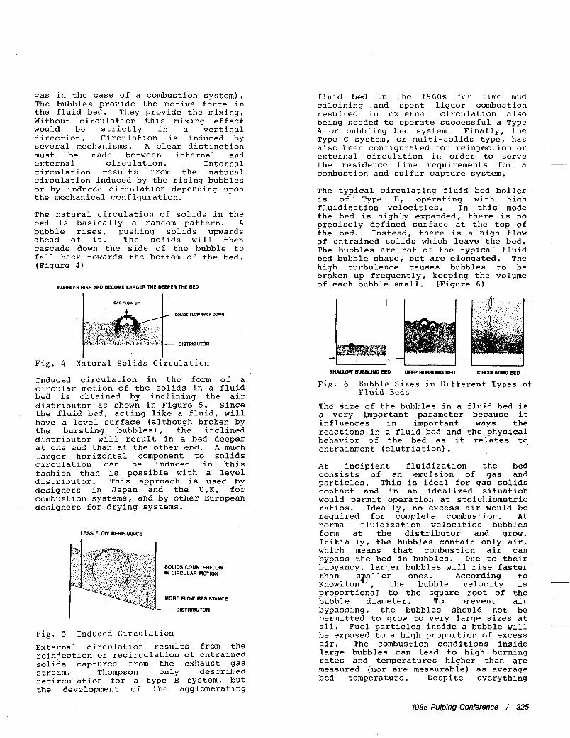
gas in the case of a combustion system). The bubbles provide the motive force in the fluid bed. They provide the mixing. Without circulation this mixing effect would be strictly in a vertical direction. Circulation is induced by several mechanisms. A clear distinction must be made between internal and external circulation. Internal circulation results from the natural circulation induced by the rising bubbles or by induced circulation depending upon the mechanical configuration.
The natural circulation of solids in the bed is basically a random pattern. A bubble rises , pushing solids upwards ahead of it. The solids will then cascade down the side of the bubble to fall back towards the bottom of the bed. (Figure 4 )
BUBBLESRISEANDBECOMELARGERTHE DEEPERTHE BED
Fig. 4 Natural Solids Circulation
Induced circulation in the form of a circular motion of the solids in a fluid bed is obtained by inclining the air distributor as shown in Figure 5. Since the fluid bed, acting like a fluid, will have a level surface (although broken by the bursting bubbles), the inclined distributor will result in a bed deeper at one end than at the other end. A much larger horizontal component to solids circulation can be induced in this fashion than is possible with a level distributor. This approach is used by designers in Japan and the U.K. for combustion systems, and by other European designers for drying systems.
LESS FLOW RESISTANCE
SOLIDS COUNTERFLOW IN CIRCULAR MOTION
MORE FLOW RESISTANCE
c- DISTRBUTOR
Fig. 5 Induced Circulation External circulation results from the reinjection or recirculation of entrained solids captured from the exhaust gas stream. Thompson only described recirculation for a type B system, but the development of the agglomerating
fluid bed in the 1 9 6 0 s for lime mud calcining and spent liquor combustion resulted in external circulation also being needed to operate successful a Type A or bubbling bed system. Finally, the Type C system, or multi-solids type, has also been configurated for reinjection or external circulation in order to serve the residence time requirements for a combustion and sulfur capture system.
The typical circulating fluid bed boiler is of Type B, operating with high fluidization velocities. In this mode the bed is highly expanded, there is no precisely defined surface at the top of the bed. Instead, there is a high flow of entrained solids which leave the bed. The bubbles are not of the typical fluid bed bubble shape, but are elongated. The high turbulence causes bubbles to be broken up frequently, keeping the volume of each bubble small. (Figure 6)
~
~
SHALLOW BUBBLING BED DEEP BUBBUNQ BED c"a BED
Fig. 6 Bubble Sizes in Different Types of
The size of the bubbles in a fluid bed is a very important parameter because it influences in important ways the reactions in a fluid bed and the physical behavior of the bed as it relates to entrainment (elutriation) . At incipient fluidization the bed consists of an emulsion of gas and particles. This is ideal for gas solids contact and in an idealized situation would permit operation at stoichiometric ratios. Ideally, no excess air would be required for complete combustion. At normal fluidization velocities bubbles form at the distributor and grow. Initially, the bubbles contain only air, which means that combustion air can bypass the bed in bubbles. Due to their buoyancy, larger bubbles will rise faster than svller ones. According to Knowlton , the bubble velocity is proportional to the square root of the bubble diameter. To prevent air bypassing, the bubbles should not be permitted to grow to very large sizes at all. Fuel particles inside a bubble will - ~~
be exposed to a high proportion of excess air. The combustion conditions inside large bubbles can lead to high burning rates and temperatures higher than are measured (nor are measurable) as average bed temperature. Despite everything
Fluid Beds
__
1985 Pulping Conference / 325
which has been said about the absence of sintering and slagging in a fluid bed, excessive bubble size can lead to unanticipated ash fusion problems in a fluid bed.
Distributor design has some influence on bubble size, but the relationship between bed height and fluidization velocity are more important. In a shallow bed there is no problem with large bubble for- mation. Since a deeper bed is required for the residence time needed to permit the reactions between calcium and sulfur, tradeoffs need to be made. The high turbulence of a circulating fluid bed keeps bubble size small and the extended bed height offers high residence time. This seems to be the best explanation for the lower calcium to sulfur ratio possible for equal SO control in a circulating bed. (It i% fascinating to compare the similar considerations in two-phase flow 05 gas/liquid described by Reeve, et a1 , for bubbles in chlorination of pulp.)
ENTRAINMENT
1
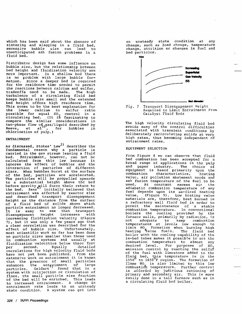
A s discussed, Stokes' Law2) describes the fundamental reason why a particle is carried in the gas stream leaving a fluid bed. Entrainment, however, can not be calculated from this law because it ignores the effect of bubbles and the interaction of particles of different sizes. When bubbles burst at the surface of the bed , particles are accelerated. The particles wi 11 be propelled upwards to a substantial height above the bed before gravity ill force their return to the bed. Zenzd initially believed that entrainment was affected by reactor size and described transport disengagement height as the distance from the surface of a fluid bed of solids above which particle entrainment no longer decreased. It is easy to see that transport disengagement height increases with increasing fluidization velocity (Figure 7), but it was only a few years ago that a clear correlation was described for the effect of bubble size. Unfortunately , most scientific work so far has been done on particle sizes smaller than those used in combustion systems and usually at fluidization velocities below three feet Per second. Equally detailed correlations for high velocity fluid beds have not yet been published. From the extensive work on entrainment it is known that the presence of small particles enhances the inment of large particles. Geldz:FQ found that in a system with reinjection or circulation of fines, the small particle size fraction of the bed will be enriched. This leads to increased entrainment. A change in entrainment rate leads to an unsteady state condition. A system can get into
an unsteady state condition at any change, such as load change, temperature change, attrition or changes in fuel and bed particles.
nm
mttimwu
Fig. 7 Transport Disengagement Height Required to Limit Entrainment From Catalyst Fluid Beds
The high velocity circulating fluid bed avoids many of the control difficulties associated with transient conditions by deliberately recirculating solids at very high rates, thus becoming independent of entrainment rates.
EQUIPMENT SELECTION
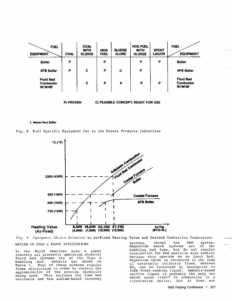
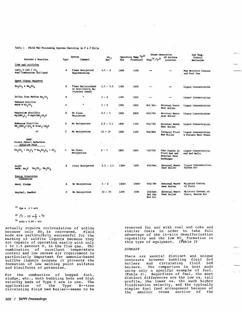
From Figure 8 we can observe that fluid bed combustion has been accepted for a broad range of applications in the pulp and paper industry. The choice of equipment is based primarily upon the combustion characteristics, heating value, air pollution abatement needs and ash fusion temperature of the fuel to be used. At constant excess air the adiabatic combustion temperature of any fuel depends upon its as-fired heating value. (Figure 9 ) . Low heating value materials are, therefore, best burned in a refractory wall fluid bed in order to permit the maintenance of a stable combustion temperature. In conventional boilers the cooling provided by the furnace walls, primarily by radiation, is not adequate to keep combustion temperatures at levels low enough to limit NOx formation when burning high heating value fuels. The fluid bed boiler with the cooling capability of the in-bed tubes makes it possible to set the combustion temperature to almost any desired level. For purposes of SO2 emission control by reacting the sulfur of the fuel with limestone added to the fluig bed, t&is temperature is in the 1550 to 1650 F region. The formation of €lame NO is also limited by this low combustioXn temperature. Further control is afforded by judicious rationing of primary and secondary air. This is more easily done in a tall furnace such as in a circulating fluid bed boiler.
326 / TAPPI Proceedings
Y EQUIPMENT
P
P
Boiler
AFB Boiler
Fluid Bed Combustor WIWHB'
Boiler
AFB Boiler
Fluid Bed Combustor WIWHB'
COAL
P
P
COAL WITH
SLUDGE
C
C
HOG FUEL 1 SLUDGE HOG 1 WITH FUEL ALONE SLUDGE
P) PROVEN C) FEASIBLE CONCEPT, READY FOR USE
1. Waste Heat Boiler
Fig. 8 Fuel Specific Equipment Use in the Forest Products Industries
"C ( O F )
2200 (4000)
980 (1800)
890 (1650)
730 (1350)
Heating Value (As-Fired)
Cooled Furnace
- - AFB Boiler
I I I -z I ' I
I I I I + 9,200 16,200 23,100 27,700 kJ/kg (4,000) (7,000) (10,000) (12,000) (BTU / Ib.)
Fig. 9 Equipment Choice Relative to As-Fired Heating Value and Desired Combustion Temperature __
systems, except the DAR system. Magnesium based systems are of the REVIEW OF PULP & PAPER APPLICATIONS
In the North American pulp & paper industry all presently operating chemical fluid bed systems are of the Type A bubbling bed. Details are shown on Table 1. Most of these systems require fines reinjection in order to control the agglomeration of the process chemicals being used. This includes the lime mud calciners and the sodium-based recovery
bubbling bed type, but do not require reinjection for bed particle size control because they operate on an inert bed. Magnesium oxide is recovered in the form of externally collected fines, whereas SO2 can be recovered by absorption to form fresh cooking liquor. Ammonia-based sulfite liquor is probably the only one which lends itself to combustion in a. circulating boiler, but it does not.
1985 Pulping Conference / 327
Table 1 Fluid Bed Processing System -rating i n P & P Mills
Sulfur Free Medium Na2C03
Ncllwood Alkaline NacM -b Na2C03
Magnesium B i s u l f i t e Ms (KO3) * W2S02+H20
Anmonim Bisul f i te NH3 cm3, +io2+ N+so*+w*o
or
DAW D i r e c t Alkali Reduction
Alkaline Pulp
N a p 3 + Fe203+ Na2Fe204 + C02
Hogfuel, sawh3t
- MLA Moisture Cmtent A Fines Reinjected 3.5 - 4 1600 1600 -- Agglonerating and Fuel use
Liquor Concentration A Fines Recirculated 2.5 - 3.5 1300 1000 -- -- or A r t i f i c a l l y Re- injected (seed)
A Liquor ConcMtration 3 - 4 1300 1000 -- --
A 3 - 5 1300 1000 450 Sat. E+xnal W a s t e Liquor Comentration H e a t Boiler
1800 650/700 Brternal W a s t e Liquor Concentration A NoFines 2.5 - 5 1600 Rein]ected Heat Boiler
A NoReinjection 2.5 - 3.5 1400 1500 650/700 Wema1 W a s t e Liquor concentration
C NoIIeinjection 10 - 15 1500 1600 900/800 In tegra l Fluid L i w r Concentcation 6 ~urnace Wall Tuhes
Heat Boiler
Bed Boiler
C NoFines 6 - 7 1800 1800 750/750 TUIB Panels in Ldquor concentration Reinjection Fluid Bed and and Bed Walls
Qszernal H e a t Fxchanger
Heat Boiler &cess A i r A Fines Reinjected 2.5 - 3.5 130W 1000 450/Sat. Ekterna1 W a s t e Liquor Concentration,
A NoReinjection 3 - 6 1400+ 1400+ 650/700 External W a s t e Moisture Content Heat Boiler of Fuels
c No Reinjection 10 - 15 1200 1500 25O/Sat. Ekteml Waste Moisture Content of H o t Gas H e a t Boiler hels, EXCESS A i r Hot A5x
l) fps x .3 = m/s
’) (% - 32) x 9 = OC
’1 PSIG x 6.89 = kpa 5
actually require recirculation of solids because only SO2 is recovered. Fluid beds are particularly successful for the burning of sulfite liquors because they are capable of operating easily with only 1 to 1.5 percent 0, in the flue gas. The combination of excellent temperature control and low excess air requirement is particularly important for ammonia-based sulfite liquors because it prevents the formation of low melting point sulfates and bisulfates of potassium.
For the combustion of hogged fuel, sludge, etc., both bubbling beds and high velocity beds of Type C are in use. The application of the Type B--true circulating fluid bed boiler--seems to be
reserved for use with coal and coke and similar fuels in order to take full advantage of the in-situ desulfurization capability and the low NO formation in this type of equipment.
SUMMARY
There are several distinct and unique contrasts between bubbling fluid bed boilers and circulating fluid bed boilers. The comparison is best made using only a specific example of fuel. (Table 3 ) . Regardless of fuel, the most distinct differences are the low vs. tall profile, the lower vs. the much higher fluidization velocity, and the typically simpler fuel feed arrangement because of the smaller cross section of the
(‘?able 2)
328 / TAPPl Proceedings
Table 2 Fluid Bed Boiler Designs
Fuel systfm
Tvpe camwt
coal, Liqnite, Preparation Plant Waste A Recirculation
B Circulating Fuel 6 Ash
petroleum Coke
wmd
B Circulating
A NO Recirculation
B Circulating Ash
3 - 6 1400- 1400-1600 1500/1000 Inteqral
12 - 20 1400- 1400-1600 2500/1000 Integral
1600
1600
12 - 20 1700 1700 1500/1000 Integral
3 - 6 1400 1500 1800/900 Integral
12 - 20 1500 1500 1200/900 Integral
l) fps x . 3 = m/s
2, (OF - 32) x 2 = OC
3, PSIG x 6.89 = kPa 5
Table 3 Unique Contrasts Between Bubbling & Circulating Bed Boilers for Coal
Bubbling Bed Circulating Bed
In-bed tubes No in-bed tubes
Law profile Tall profile
Large airflow area
Underbed feed
Small airflow area
In-bed feed (1 or 2 points) 2 (1 pint per2.5 - .8 m
[6 - 9 ft ] air flow area) or
overbed feed (1 or 2 points)
circulating bed boilers. An idealized match of fuel and equipment is shown on Table 4 . It must be remembered that the particle size of a given fuel may dictate the choice of equipment more than anything else. For example, the combustion characteristics of coke would make it an ideal fuel for a bubbling bed; but because the particle size of most coke offered as low-cost fuel is extremely small, the Type B circulating fluid bed boiler is needed to prevent excessive fuel loss.
The height requirements of circulating fluid bed boilers may make them undesirable for capacities under 100,000 pound per hour, but they do offer greater simplicity of solids handling, closer and more consistent air/fuel ratio, and
In-Bed Tubes & Walls
Walls, Solids Circulation
walls, solids Circulation
In-Bed Tubes & Walls
Walls, Solids Circulation
better operating stability over the entire range of their design capacity.
1985 Pulping Conference / 329
Table 4 An Idealized Characterization of Fuel and Equipnent Match
T y p e A B e d TypeB&CBed
Particle size range') 40 mesh - 5 mn [1/16"] Particle size range2) 300 mesh - 50 mn [2"] H i g h Ash LowAsh
Steady state bed, except fuel. Fuel particle size ut may be < uo. 3, Overfire air (secondary air).
REFERENCES
1.
2.
3.
4 .
5.
6.
7 .
R. B. Thompson, G. Roesner, Fluid Bed Roasting - Principles and Practice Perry, Chemical Engineering Handbook
-
Fluidized Beds, Combustion and Applications, Edited by J. R. Howard, Applied Science Publishers, London & New York
T. M. Knowlton, Determining Bubble Properties in Fluidized Beds Using Pressure Probes, Institute of Gas Technology, Chicago, Illinois, 1985
D. W. Reeve, et all Chlorine Gas Dispersion Optimizes Chlorination and Redices Corrosion, Pulp & Paper, March 1985
F. A. Zenz, Particulate Solids, The Third Fluid Phase in Chemical Engineering, Chemical Engineerinq, November 28, 1983
P. Geldart, Behavior of Fine Particles in a Fluidized Bed of Coarse Solids, University of Bradford, England, October 1981, research program for Electric Power Research Institute
Graph 1 Schytil's Phase Diagram of Gas- Solid Suspensions