Copyright2016InterCAXLLC1
75 Fifth Street NW, Suite 312 Atlanta, GA 30308, USA voice: +1-404-592-6897 web: www.Intercax.com
email: [email protected]
DirkZwemer,IntercaxLLC
Technote: Application of MBE to Automotive Engineering
Introduction.............................................................................................................................................1
Syndeia.....................................................................................................................................................2
SystemArchitectureModel.....................................................................................................................3
Inter-modelConnections.........................................................................................................................5
VisualizingtheTotalSystemModel.........................................................................................................5
TheFutureofMBEforAutomotiveandTransportationApplications.....................................................7
AbouttheAuthor....................................................................................................................................7
Introduction Engineeringintheautomotiveindustryfacesabroadsetofchallenges:
• Rapidlychangingtechnologyencompassingmechanical,electronic,softwareandotherengineeringdisciplines
• Diversebodiesofrequirements:market,regulatoryandtechnical• Highproductmixandextensiveindividualcustomizationandintegration• Extendedsupplychainsacrossorganizationalandinternationalboundaries
Becauseofthesechallenges,automotiveengineershavebeenleadersindevelopingandadoptingadvancedtechniquesinsystemsengineering.Theirengineeringtoolneedsinclude
• Anarchitecturalframeworkinclusiveofstructure,behavior,requirementsandanalysis• Cross-vendorandcross-disciplineinteroperability• Easy-to-use,non-discipline-specificqueryandvisualizationcapabilities
Model-BasedEngineering(MBE)dependsonasingle,self-consistentdigitalmodelofthesystem,spreadacrossmultipleengineeringtoolsandrepositories,asillustratedinFigure1.ItextendstheconceptofModel-BasedSystemsEngineering(MBSE)ofcapturingasystem’sspecificationasamodel,ratherthanaseriesofstaticdisconnecteddocuments.AstheMBSEideadeveloped,itbecameclearthatasinglemodelinasingletool,forexample,aSysMLsystemarchitecturemodel,wasinsufficientforthepurpose.
Copyright2016InterCAXLLC2
InModel-basedEngineering,allthedisciplinesandtoolsintheengineeringprocessareengagedinanongoingnetwork.
Figure1TotalSystemModelasaNetworkofConnectionsinsideandbetweenEngineeringSoftwareToolsandRepositories
Syndeia Syndeia™,fromIntercax,isaplatformforthepracticeofMBE.AsshowninFigure2,itusesasystemarchitecturemodelascentralhubandconnectsSysMLelementstoelementsinPLM,CAD,ALM(applicationlifecyclemanagement),projectmanagement,requirements,simulationandotherengineeringtools.
SysMLisaneffectivemediumforbuildingahigh-levelroadmapofthesystembecauseitprovidesarichlanguageforconnectingstructure,behavior,requirementsandanalysisconcepts,conceptsthatcanmaptocorrespondingconceptsinmorespecializedtools.Currently,SyndeiasupportstwoSysMLmodelingtools,MagicDraw(NoMagicInc.)andIBMRationalRhapsody,andavarietyofothertools,including
TeamcenterandNX(Siemens),WindchillandCreo(PTC),MySQL(Oracle),DOORSNG(IBMRational),Simulink(TheMathworks),JIRA(Atlassian),GitHub(GitHub,Inc.)andExcel(Microsoft).ContactIntercaxtolearnaboutsupportforothertools.
Figure2Syndeiaarchitecture
Copyright2016InterCAXLLC3
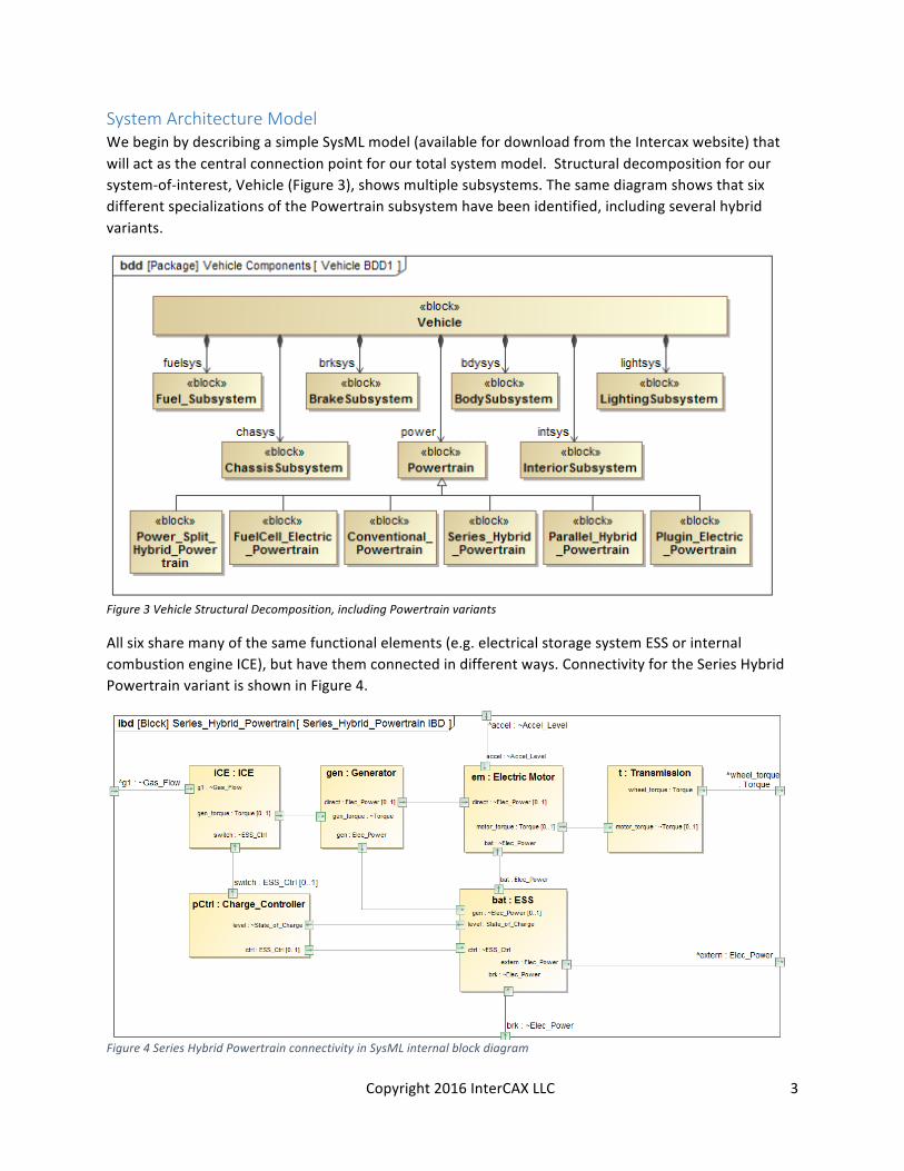
System Architecture Model WebeginbydescribingasimpleSysMLmodel(availablefordownloadfromtheIntercaxwebsite)thatwillactasthecentralconnectionpointforourtotalsystemmodel.Structuraldecompositionforoursystem-of-interest,Vehicle(Figure3),showsmultiplesubsystems.ThesamediagramshowsthatsixdifferentspecializationsofthePowertrainsubsystemhavebeenidentified,includingseveralhybridvariants.
Figure3VehicleStructuralDecomposition,includingPowertrainvariants
Allsixsharemanyofthesamefunctionalelements(e.g.electricalstoragesystemESSorinternalcombustionengineICE),buthavethemconnectedindifferentways.ConnectivityfortheSeriesHybridPowertrainvariantisshowninFigure4.
Figure4SeriesHybridPowertrainconnectivityinSysMLinternalblockdiagram
Copyright2016InterCAXLLC4
Thesystemarchitecturemodelcanalsoincludesystemrequirements,especiallywhereseparaterequirementtypesarerelatedtoeachotherortoothersystemelements.Figure5showsseveralexamplesofsuchrelationships,wheretechnicalrequirementsareshownasderivedfrommarketrequirementsandsatisfiedbystructuralelementsofthesystem.
Figure5SampleSysMLconnectivitybetweenmarketrequirements,technicalrequirements,andstructureThesystemarchitecturemodelalsodescribesthebehaviorsorfunctionsofthesystemanditsparts.InFigure6,theoverallfunctionoftheserieshybridpowertrainisdecomposedintoaseriesofsubfunctions(actions),eachofwhichisallocatedtoastructuralcomponent.Theseallocationdependenciesareindicatedbytheswimlanesintheactivitydiagram.
Figure6SysMLActivitydiagramforSeriesHybridPowertrain,withallocationstostructuralcomponentsAlltherelationshipsshowninthesefigures,representingcomposition,dependencyandflow,are“intra-model”connections,connectionscreatedandstoredwithinasinglesoftwaretool,inthiscase,theSysMLmodelingtool.ButmanyofthesesameSysMLelementsalsorelatetoelementsinother
Copyright2016InterCAXLLC5
softwaretools.Theseare“inter-model”connections,whichwewillcreate,manageandusewithSyndeia,asdescribedinthenextsection.
Inter-model Connections Inter-modelconnectionsaremadeusingtheSyndeiadashboard(Figure7)usingavarietyofdrag-and-dropmechanisms.Inoursamplemodel,
• MarketandtechnicalrequirementsweredraggedfromtwodifferentPLMrepositoriesintotheSysMLmodel,retainingtheirhierarchicalstructures;
• Structuralconnectivity(e.g.Figure4)weredraggedfromSysMLintoMATLAB,creatingaSimulinkblockstructure(blocks,portsandsignals,butnointernalMATLABcode);
• SinglereferencelinkswerecreatedfromSysMLactivitiestosoftwarefoldersinGitHub.
Figure7SyndeiadashboardshowingSysMLandTeamcenterPLMrepositorycontentssidebyside.
Ineachcase,theelementsremainconnected,linkingthemodelsindifferenttoolsintoasinglesystemmodel,theultimateobjectiveofMBE.Dependingonthenatureoftheconnection(andthecapabilityofthetoolsinvolved),theseconnectionscansupportusecasesofpracticalvaluetoengineering,including
• CompareandsynchronizeSysMLblockstructurewithPLMbill-of-materialsorSimulinkblockstructureastheyevolveovertime
• UpdateSysMLrequirementsfromamasterrequirementsrepository• OpenandviewCADmodelsorprojectmanagementissuetrackersdirectlyfromthesystem
model
Visualizing the Total System Model Asthenumberofconnectionsgrows,ourabilitytounderstandthescopeandcomplexityofthetotalsystemmodelandtoidentifyextendedlinkagesbetweenelementsdiminishes.Weneedtobeableto
Copyright2016InterCAXLLC6
viewthesystemmodelgloballyandtotraceconnectionslocally.Syndeia3.0offersbothforautomotiveapplications.
Figure8showsaglobalviewoftheinter-modelconnectionsinachordplot.Theupperrightboxreportsthat73elementsareconnectedby42Syndeia-managedconnections.TheelementsontheperipheryofthecirclerepresentSysML(orange),Teamcenter(red),Simulink(blue),GitHub(green)andJIRA(beige)elements.Thenodesandthelinesbetweenthemcanbeinteractivelyhighlightedandidentifiedinthelightblueboxontheupperright,andtheentireplotcanbesearchedandfiltered.Usingthis,thesystemengineercanseeataglancethetypesofelementsbeingconnectedandthedensityofconnectionsinthecurrentstateofthemodel.
Figure8ChordplotofInter-modelConnections–GlobalVisualizationWhiletheglobalviewinFigure8givesthebigpicture,manyusecasesinvolvetracingextendedlinkagesoverbothinter-modelandintra-modelchains.Alternategraphingtechniquescanmakethistasksimpler.OneexampleisshowninFigure9,atreeplotinitiatedfromaspecificmodelelementintheSysMLmodelortheSyndeiadashboard.LaunchedfromaSysMLactivity,DriveGenerator,itimmediatelydisplaysthreenearestneighbors,aJIRAissueandaGitHubsoftwarefolderconnectedbyinter-modelconnections(showninblack)andaSysMLblock,ICE,connectedbyanintra-modelconnection(showninorange).Thislastnodecanbefurtherexpandedbyclickingonit,showinganadditionalfournextnearestneighborsandtheprocesscanbecontinuedselectivelyuntilthechainisterminated.Intheresultingplot,theextendedlinkagebetweentheTeamcenterrequirementatthebottomleft,theSysMLfunctionitimpacts,andtheJIRAissuethatrecordsthatimpact,istracedoverfiveconnectionsacrossthreetools.Considerthevalueoftheseapproachesinexpeditingdesignreviews,withexplicitconnectionsbetweensystemelementsandtheabilitytoopenthoseelementsintheirnativetoolsfromacentralhigh-levelroadmapofthesystem.
Copyright2016InterCAXLLC7
Figure9TreeplotofInter-modelandIntra-modelConnectionsdemonstratingtraceabilityacrossgraph
The Future of MBE for Automotive and Transportation Applications ThefieldofModel-BasedEngineeringisevolvingrapidly.DrivenbynewtechnologiesliketheInternet-of-ThingsandSmartGridenergysystems,engineeringsoftwaretoolsarebeingpushedtothelimits.Automotivesystemsengineers,workingoninnovationslikeAutonomousVehicles,willneedtobeattheforefrontofthesedevelopments.
Tomeettheirneeds,MBEtoolswillneedtoevolve,aswell.ASysML-centricarchitecture,asillustratedbySyndeia,willbenomoreeffectivethanaPLM-centricoraCAD-centricone.MBEtoolswillfunctionaswebservices,providingacompletepictureoftheTotalSystemModelfromanypositionintheengineeringprocess.Powerfulgraphdatabaseswillprovidescaleabilityandsophisticatedquerycapabilityforidentifyingextendedconnections.Userscaninteractwiththegraphthroughsophisticatedmodelingtoolsorsimplifiedwebinterfaces,usingtheirchoiceoflaptop,tabletorhandhelddevice.
About the Author Dr. Dirk Zwemer ([email protected]) is President of Intercax LLC (Atlanta, GA), a supplier ofMBEengineeringsoftwareplatformslikeSyndeiaandParaMagic.Heisanactiveteacherandconsultantin the field and holds Level 4 Model Builder-Advanced certification as an OMG System ModelingProfessional.Forfurtherinformation,[email protected].