Applications of Rain Field Modeling in Radio Communications Dr Sarah Callaghan STFC – Rutherford Appleton Laboratory Radio Communications Research Unit, Chilton Didcot, OX11 0QX, United Kingdom Email: [email protected]
Transcript
Applications of Rain Field Modeling in Radio Communications
Dr Sarah CallaghanSTFC – Rutherford Appleton Laboratory
Radio Communications Research Unit, ChiltonDidcot, OX11 0QX, United Kingdom
Introduction The market for mobile phones is saturated, so the commercial push is for
new applications to encourage users to increase usage of the operators’ services
The UK spectrum auction for 3G mobile licenses in March 2000 resulted in a total of 22 billion pounds being spent by the mobile phone companies to buy the rights to certain bands of the radio spectrum
These licenses are needed in order to provide 3G services like mobile internet and TV-on-demand. These services are very bandwidth-intensive, and the radio spectrum at mobile phone frequencies is very congested, but the UK government wants to encourage growth in this technological area
So, what can we do?
1. Improve spectrum efficiency at lower frequencies
2. Open up higher frequencies (which are under-used) to commercial exploitation
Improving spectrum efficiency
Link allocations in the 38 GHz band in the UK. Total: 13,949 links
Is there a way to pack more links into a given geographical area or a given frequency band?
Link distribution in space in the 38 GHz band in the UK.
Opening higher frequencies to commercial exploitation
Attenuation statistics from satellite beacons measured in the South of
England
Radio systems operating at frequencies above 10 GHz are very
affected by the presence of rain, light rain and clouds along the radio path. Fixed radio links can be earth-space
or terrestrial.
It doesn’t rain everywhere all the time!
For frequencies > 10 GHz, rain is the dominant cause of attenuation.
We can take advantage of the spatio-temporal variation in rain fields to implement rain Fade Mitigation Techniques (FMTs) to improve spectrum efficiency and open up higher frequencies to commercial exploitation.
Stratiform event Convective event
Example radio systems affected by rain: terrestrial network using route diversity
Route diversity involves routing a radio signal through different links which bypass the rain-affected link to get to the same receive point.
Best case for this is when the rain is de-correlated (localised rain) as neighbouring links in the network will be unaffected and can be used to route the data around the affected link.
Data sent from yellow to red
Data sent from yellow to red via blue
Example radio systems affected by rain: terrestrial network using ATPC
Adaptive Transmit Power Control involves turning the transmit power up to compensate for rain fading. This also increases the transmit power on the sidelobes and unwanted paths, increasing interference into neighbouring links.
Best case is when the rain field is correlated (widespread rain) as the interfering path will then be as attenuated as much as the wanted path, so turning up the power will produce no real change in interference.
Wanted path
Wanted path
Interfering path
• 25 m diameter steerable antenna• 60 m tall• Dish weighs 400 tonnes, tower weighs 2000 tonnes • 3 GHz Doppler-Polarization radar• operational range of 100 km• beam width of 0.25 degrees• max angular velocity 1 degree / second
Meteorological radar data gives data with very good resolution, which is important when studying the fine detail in rain fields.CAMRa
Chilbolton Advanced Meteorological Radar
http://www.chilbolton.rl.ac.uk/weather/
Convective Rain – Italsat Earth-Space data
Date of scan: 17/ 6/ 1998Time covered by scan: 10:20 – 13:40Maximum radar reflectivites: 48 dBZMaximum beacon attenuation:50GHz:40GHz:
25 dB13 dB
Maximum rain rate recorded: 25mm/ hrRadiosonde:Time:Height of 0°C isotherm
No data for that date.
Comparison of radar measurements along the path, with concurrent rain gauge and satellite beacon attenuation measurements.
Convective rain cell
Stratiform Rain – Italsat Earth-Space Data
Date of scan: 8/ 6/ 1998Time covered by scan: 12:50 – 15:10Maximum radar reflectivites: 30 dBZMaximum beacon attenuation:50GHz:40GHz:
13dB7dB
Maximum rain rate recorded: 9mm/ hrRadiosonde:Time:Height of 0°C isotherm
10:003km
Comparison of radar measurements along the path, with concurrent rain gauge and satellite beacon attenuation measurements.
Stratiform rain
Example radar map of the UK derived from the Met Office Nimrod radar data
What rain radar data is available?
Answer: lots. One dataset is the Met Office’s Nimrod data set, which is a database of rain radar measurements available which is composite rain radar data on the Cartesian national grid.
Space resolution: 1/2/5km hybridTime resolution: 5 minutes
Database starts in April 2004.
Before that, composite rain radar data is available on a space resolution of 5 km * 5 km and at a time resolution of 15 minutes.
Can we use the Met Office Nimrod rain radar database to simulate fixed radio link scenarios?
Stratiform event recorded on the 12th January 2004.
Convective event recorded on the 9th January 2004.
This database is an extremely useful resource for systems designers. However, in this case, the spatial resolution is not high enough to be able to accurately use the data as a substitute for the beacon measurements made in the GBS site diversity experiment. We either need to make more fine-scale measurements (100mx100m pixel size, at time intervals of less than 1 minute) or look at producing simulated rain fields.
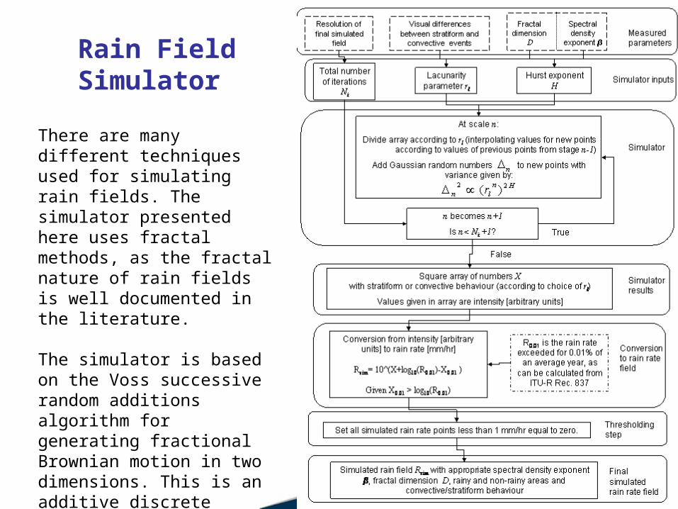
Rain Field Simulator
There are many different techniques used for simulating rain fields. The simulator presented here uses fractal methods, as the fractal nature of rain fields is well documented in the literature.
The simulator is based on the Voss successive random additions algorithm for generating fractional Brownian motion in two dimensions. This is an additive discrete cascade, producing log, monofractal fields.
Example simulated rain fields
Example simulated stratiform rain field. Example simulated convective rain field.
Each run of the simulator produces a single realisation of a stratiform-like or a convective-like rain field. These realisations are independent of each other, hence
there is no temporal component to the model (work is ongoing).However, given enough synthetic fields we can create simulated statistics for an
average year.
Example simulated stratiform rain field. Example simulated convective rain field.
Applying rain field data to an engineering scenario
Ofcom funded a project to investigate the impact of introducing Automatic Transmit Power Control (ATPC) into the 38 GHz fixed terrestrial links band. This involved using the same methods as Ofcom’s existing frequency assignment software, and modifying it to take ATPC into account. It was tested with measured and simulated rain fields.
out.svgout.svgout.csvout.csv
PLANPLAN
in.flpin.flp
out.flpout.flp
ExcelExcel(38 GHz)(38 GHz)
out.csvout.csvout.flaout.fla
ANALYSEANALYSE
rain datarain data
Band planning and analysis flowchart
Results from ATPC project and Conclusions
Band EfficiencyBand Efficiency13500 assignments13500 assignmentsplan-(large)plan-(large)
0 50 100 150 200 250 300 350
Frequency Offset (MHz)
10,000
1,000
100
10
1
Nu
mb
er
of
Lin
ks
56 MHz
28 MHz
14 MHz
7 MHz
3.5 MHz
Band EfficiencyBand Efficiency13527 assignments13527 assignmentsplan-(forward-om-5-mix-100)plan-(forward-om-5-mix-100)
0 50 100 150 200 250 300 350
Frequency Offset (MHz)
10,000
1,000
100
10
1
Nu
mb
er
of
Lin
ks
56 MHz
28 MHz
14 MHz
7 MHz
3.5 MHz
Non-ATPC
ATPC
Using ATPC in the 38 GHz band gives significant improvements in spectrum efficiency measured by:
1. the increase in the number of links assigned to channel 1 (from ~50% to ~70%)
2. the decrease in the maximum bandwidth used (from ~300 MHz to ~180 MHz).
The model used here produces rain fields with spatial resolution of 100m*100m and a time resolution of 1 minute.These fields have the same fractal dimension, spectral density exponent and spatial autocorrelation function as measurements, and can be customised to different climatic regions.
They also produce stratiform-like and convective-like behaviour, according to the type of event desired by the operator.