1 Applications of rare-earth permanent magnets in electrical machines: from motors for niche applications to hybrid electric vehicles S. J. Collocott, J. B. Dunlop, P. B. Gwan, B. A. Kalan, H. C. Lovatt, W. Wu, CSIRO Division of Telecommunications and Industrial Physics, Lindfield, NSW, Australia 2070 and P. A. Watterson Faculty of Engineering, University of Technology, Sydney, NSW, Australia 2007 Abstract: The advent of modern rare-earth permanent magnets, which have a magnetic energy product up to an order of magnitude greater than those of Alnico and ferrite magnets, with high remanence and coercive force, has resulted in improved performance of many devices and products. Modern rare-earth magnets, especially neodymium-iron-boron, when combined with technological advances in power and control electronics, computational techniques based on finite-element methods, and new generation soft magnetic materials, have had a major impact on electric machine design. These technologies have resulted in state-of-the-art electrical machines that are compact, of high efficiency, and high torque and power outputs per unit volume. Such machines have been integral to the success of a number of mass market consumer applications, for example computer disk drives, camcorders, CD and DVD players etc. Several innovative electrical machines are reviewed that have been developed by the CSIRO Division of Telecommunications and Industrial Physics and by the Faculty of Engineering, University of Technology, Sydney, (UTS), for a number of niche applications. In each case the machine pushes the boundary of electric machine design, and results in a machine that has unique features, such as compactness, high efficiency or high torque per unit volume. These attributes are in large part a benefit of the use of rare-earth permanent magnets. Machines discussed include a sheep shearing hand-piece, a direct drive actuator, an implantable centrifugal blood pump, a motor for a solar powered racing car and a permanent magnet generator for a series hybrid electric vehicle. All use neodymium-iron-boron magnets on the rotating part of the motor and a three phase winding on the stationary part (or “stator”). Keywords: rare-earth magnets, electric machines, hybrid electric vehicles
Transcript
1
Applications of rare-earth permanent magnets in electrical machines:
from motors for niche applications to hybrid electric vehicles
S. J. Collocott, J. B. Dunlop, P. B. Gwan, B. A. Kalan, H. C. Lovatt, W. Wu,
CSIRO Division of Telecommunications and Industrial Physics,
Lindfield, NSW, Australia 2070
and
P. A. Watterson
Faculty of Engineering, University of Technology, Sydney, NSW, Australia 2007
Abstract: The advent of modern rare-earth permanent magnets, which have a magnetic energy
product up to an order of magnitude greater than those of Alnico and ferrite magnets, with high
remanence and coercive force, has resulted in improved performance of many devices and products.
Modern rare-earth magnets, especially neodymium-iron-boron, when combined with technological
advances in power and control electronics, computational techniques based on finite-element
methods, and new generation soft magnetic materials, have had a major impact on electric machine
design. These technologies have resulted in state-of-the-art electrical machines that are compact, of
high efficiency, and high torque and power outputs per unit volume. Such machines have been
integral to the success of a number of mass market consumer applications, for example computer
disk drives, camcorders, CD and DVD players etc.
Several innovative electrical machines are reviewed that have been developed by the CSIRO
Division of Telecommunications and Industrial Physics and by the Faculty of Engineering,
University of Technology, Sydney, (UTS), for a number of niche applications. In each case the
machine pushes the boundary of electric machine design, and results in a machine that has unique
features, such as compactness, high efficiency or high torque per unit volume. These attributes are
in large part a benefit of the use of rare-earth permanent magnets. Machines discussed include a
sheep shearing hand-piece, a direct drive actuator, an implantable centrifugal blood pump, a motor
for a solar powered racing car and a permanent magnet generator for a series hybrid electric vehicle.
All use neodymium-iron-boron magnets on the rotating part of the motor and a three phase winding
on the stationary part (or “stator”).
Keywords: rare-earth magnets, electric machines, hybrid electric vehicles
2
1. INTRODUCTION
In September 1821 Michael Faraday demonstrated continuous circular movement and arguably
produced the first electric motor [1]. In a space of a little over 150 years the electric motor and
related devices have become a ubiquitous feature of the modern world. Electric motors underpin
modern industry, from steel mills to process control to automated robotic manufacture. Indeed, in
modern industrialized western economies electric motors consume 40-45% of all electrical energy
generated, most of this energy being consumed in large industrial drives. In our every day life, we
are surrounded by electric motors in consumer products, ranging from digital cameras, DVDs,
washing machines, dishwashers and a myriad of other domestic appliances, to motor cars, which
may contain up to forty (or more) electric motors. Not only do some products contain many motors,
but where there is a motor there is likely to be power and control electronics. Electric motor
technology is continuously evolving, with constant pressure for enhanced performance. In particular
improved efficiency of grid-connected electric motors is sought, as there is an increasing awareness
of the consequences of global warming, due to the emission of the greenhouse gas, CO2, from large
coal-fired power stations. Similar issues apply in small motors in portable devices, where battery
life is important.
Here the focus is rare-earth permanent magnet (pm) brushless motors, as it is these motors that have
found application were compactness, high torque per unit volume, better dynamic response (due to
the low inertia of the rotor), reliability (no brushes) and high efficiency are prime requirements [2].
Modern permanent magnet motor drives did not happen overnight, being a result of advances in
materials science that have led to the current generation of rare-earth permanent magnets, and new
soft magnetic materials, such as amorphous or glassy metals. These materials advances, when
combined with fast computers, facilitating advances in electromagnetic circuit design using 2 and 3-
dimensional finite element techniques, and a revolution in semiconductors, that has heralded low-
cost digital microprocessors and digital signal processors (DSP) for motor control and high-power
switching devices, have impacted on electric machine technology. It should be noted that not just
rare-earth pm motors have benefited from these advances, but other motor types, such as switched
reluctance have undergone a similar transformation, and in some applications may be the motor of
choice, particularly where a constant power output profile is required and/or where low cost with
variable speed is specified. This paper will review a variety of electrical machines that have been
developed at CSIRO Telecommunications and Industrial Physics and at the University of
3
Technology, Sydney, highlighting the flexibility and the versatility of rare-earth pm brushless
motors to meet highly exacting specifications in a number of very dissimilar applications.
2. MOTOR TECHNOLOGY AND MAGNETIC MATERIALS
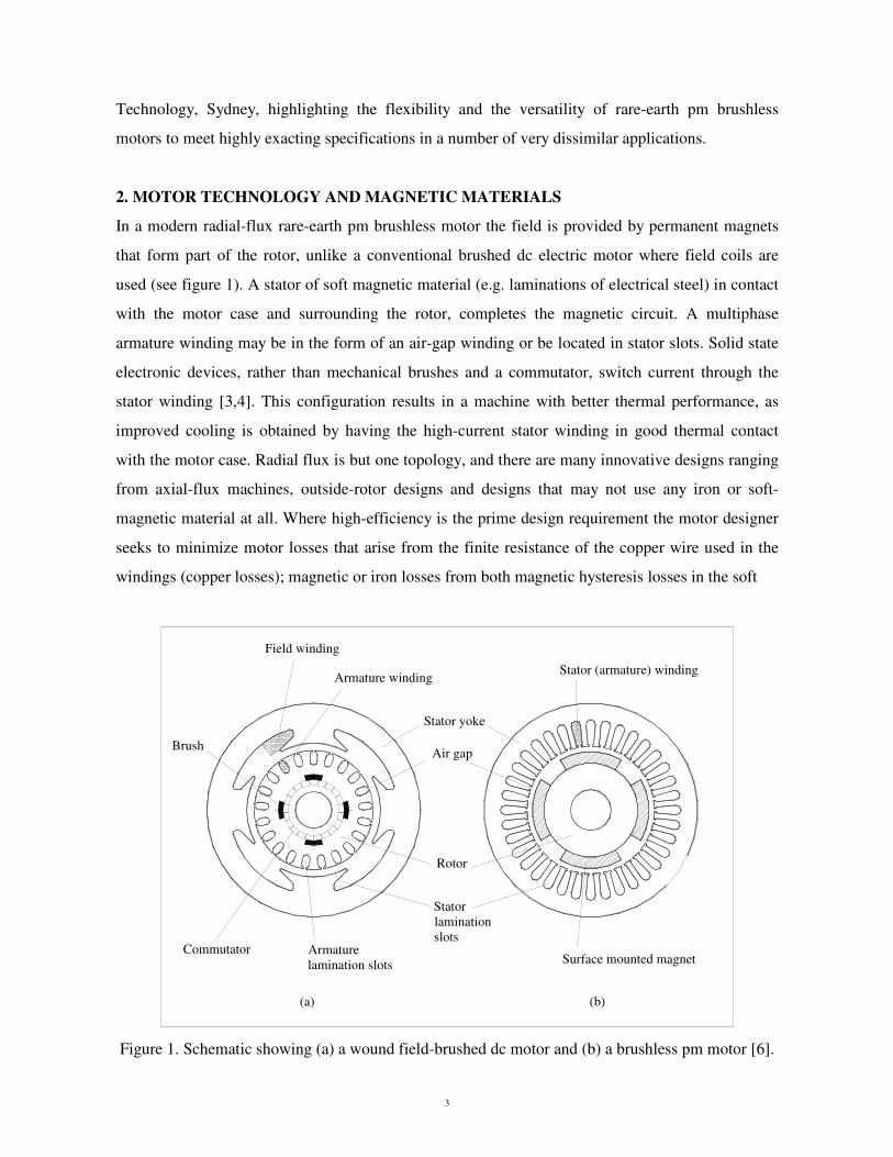
In a modern radial-flux rare-earth pm brushless motor the field is provided by permanent magnets
that form part of the rotor, unlike a conventional brushed dc electric motor where field coils are
used (see figure 1). A stator of soft magnetic material (e.g. laminations of electrical steel) in contact
with the motor case and surrounding the rotor, completes the magnetic circuit. A multiphase
armature winding may be in the form of an air-gap winding or be located in stator slots. Solid state
electronic devices, rather than mechanical brushes and a commutator, switch current through the
stator winding [3,4]. This configuration results in a machine with better thermal performance, as
improved cooling is obtained by having the high-current stator winding in good thermal contact
with the motor case. Radial flux is but one topology, and there are many innovative designs ranging
from axial-flux machines, outside-rotor designs and designs that may not use any iron or soft-
magnetic material at all. Where high-efficiency is the prime design requirement the motor designer
seeks to minimize motor losses that arise from the finite resistance of the copper wire used in the
windings (copper losses); magnetic or iron losses from both magnetic hysteresis losses in the soft
Figure 1. Schematic showing (a) a wound field-brushed dc motor and (b) a brushless pm motor [6].
4
magnetic components and eddy currents; and friction and windage losses from bearing friction,
brushes, if present, and the rotor peripheral speed [5].
The finite-element method is commonly used during the design of a machine. From the magnetic
field distribution for a particular magnetic circuit geometry the code is used to calculate key
parameters such as torque, copper loss, iron loss, no load loss, temperature rise, fundamental and
harmonic induced emf, inductance, cogging torque etc. Commercial codes are available e.g.
ANSYS, MagNet, OPERA, etc for this task. This is then followed by an optimization stage, where
the maximum (or minimum) value of an objective function (e.g. cost, efficiency) is sought over a
number of key variables, subject to the constraints of the motor specification, such as maximum
allowed motor volume, temperature rise for a given torque and speed etc.
Magnetic materials, both soft and hard, are key to the design of state-of-the-art electrical machines
[6]. The role of the permanent magnet is replacement of the field winding. Selecting the most
suitable permanent magnet material is governed by a number of factors, including
• magnetic parameters: remanence, intrinsic coercivity and magnetic energy product,
• temperature stability of the magnetic parameters,
• ease of magnetizing the material,
• ease of forming the magnet material into the desired shape,
• environmental factors, such as corrosion resistance, and
• cost, which may be material cost, cost of forming and/or cost per unit of magnetic energy
product.
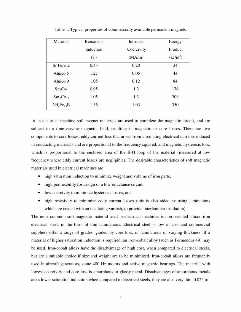
Choice of magnet material also impacts on the electromagnetic design of the machine. Rare-earth
magnets have for the machine designer the desirable attributes of high remanence, a linear B-H
curve in the second (or demagnetizing) quadrant (unlike AlNiCo for example, which is highly non-
linear), a high magnetic energy product, which reduces the amount of magnet material required, and
a high intrinsic coercivity, which reduces the risk of magnet demagnetization should high-armature
currents occur [7]. Typical properties of commercially available magnets are given in table 1.
5
Table 1. Typical properties of commercially available permanent magnets.
Material Remanent
Induction
(T)
Intrinsic
Coercivity
(MA/m)
Energy
Product
(kJ/m3)
Sr Ferrite 0.43 0.20 34
Alnico 5 1.27 0.05 44
Alnico 9 1.05 0.12 84
SmCo5 0.95 1.3 176
Sm2Co17 1.05 1.3 208
Nd2Fe14B 1.36 1.03 350
In an electrical machine soft magnet materials are used to complete the magnetic circuit, and are
subject to a time-varying magnetic field, resulting in magnetic or core losses. There are two
components to core losses, eddy current loss that arises from circulating electrical currents induced
in conducting materials and are proportional to the frequency squared, and magnetic hysteresis loss,
which is proportional to the enclosed area of the B-H loop of the material (measured at low
frequency where eddy current losses are negligible). The desirable characteristics of soft magnetic
materials used in electrical machines are
• high saturation induction to minimize weight and volume of iron parts,
• high permeability for design of a low reluctance circuit,
• low coercivity to minimize hysteresis losses, and
• high resistivity to minimize eddy current losses (this is also aided by using laminations
which are coated with an insulating varnish, to provide interlaminar insulation).
The most common soft magnetic material used in electrical machines is non-oriented silicon-iron
electrical steel, in the form of thin laminations. Electrical steel is low in cost and commercial
suppliers offer a range of grades, graded by core loss, in laminations of varying thickness. If a
material of higher saturation induction is required, an iron-cobalt alloy (such as Permendur 49) may
be used. Iron-cobalt alloys have the disadvantage of high cost, when compared to electrical steels,
but are a suitable choice if size and weight are to be minimized. Iron-cobalt alloys are frequently
used in aircraft generators, some 400 Hz motors and active magnetic bearings. The material with
lowest coercivity and core loss is amorphous or glassy metal. Disadvantages of amorphous metals
are a lower saturation induction when compared to electrical steels, they are also very thin, 0.025 to
6
0.001 0.01 0.1 1 100.0
0.5
1.0
1.5
2.0
2.5
nano-cryst.
Co-base
70-80% NiFe
amorphous Fe-base
40-50% NiFe
50% CoFe3% SiFe Fe
powder cores
soft ferrites
Sat
urat
ion
Mag
netic
Indu
ctio
n (T
)
Coercivity Hc (A/cm)
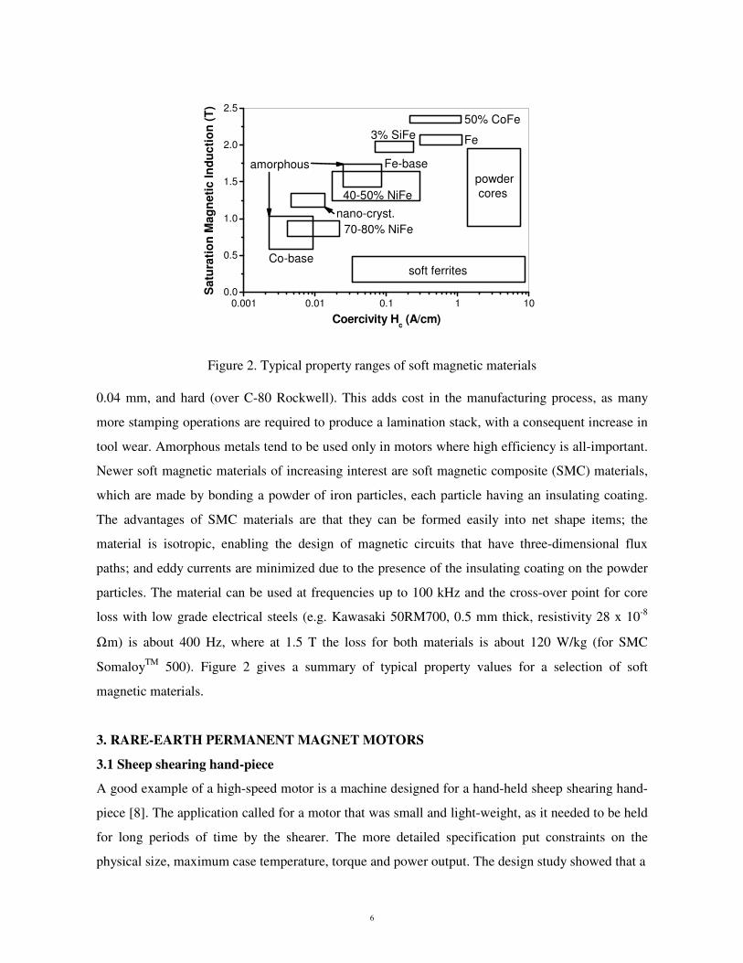
Figure 2. Typical property ranges of soft magnetic materials 0.04 mm, and hard (over C-80 Rockwell). This adds cost in the manufacturing process, as many
more stamping operations are required to produce a lamination stack, with a consequent increase in
tool wear. Amorphous metals tend to be used only in motors where high efficiency is all-important.
Newer soft magnetic materials of increasing interest are soft magnetic composite (SMC) materials,
which are made by bonding a powder of iron particles, each particle having an insulating coating.
The advantages of SMC materials are that they can be formed easily into net shape items; the
material is isotropic, enabling the design of magnetic circuits that have three-dimensional flux
paths; and eddy currents are minimized due to the presence of the insulating coating on the powder
particles. The material can be used at frequencies up to 100 kHz and the cross-over point for core
loss with low grade electrical steels (e.g. Kawasaki 50RM700, 0.5 mm thick, resistivity 28 x 10-8
Ωm) is about 400 Hz, where at 1.5 T the loss for both materials is about 120 W/kg (for SMC
SomaloyTM 500). Figure 2 gives a summary of typical property values for a selection of soft
magnetic materials.
3. RARE-EARTH PERMANENT MAGNET MOTORS
3.1 Sheep shearing hand-piece
A good example of a high-speed motor is a machine designed for a hand-held sheep shearing hand-
piece [8]. The application called for a motor that was small and light-weight, as it needed to be held
for long periods of time by the shearer. The more detailed specification put constraints on the
physical size, maximum case temperature, torque and power output. The design study showed that a
7
high-speed slotless rare-earth pm motor driving the shearing comb through a reduction gear best
met the specification.
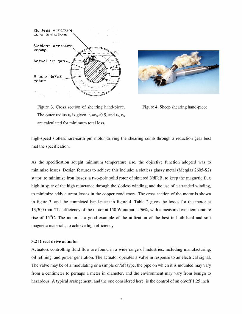
As the specification sought minimum temperature rise, the objective function adopted was to
minimize losses. Design features to achieve this include: a slotless glassy metal (Metglas 2605-S2)
stator, to minimize iron losses; a two-pole solid rotor of sintered NdFeB, to keep the magnetic flux
high in spite of the high reluctance through the slotless winding; and the use of a stranded winding,
to minimize eddy current losses in the copper conductors. The cross section of the motor is shown
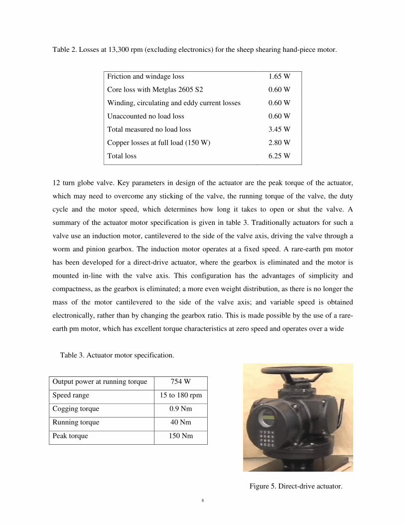
in figure 3, and the completed hand-piece in figure 4. Table 2 gives the losses for the motor at
13,300 rpm. The efficiency of the motor at 150 W output is 96%, with a measured case temperature
rise of 15OC. The motor is a good example of the utilization of the best in both hard and soft
magnetic materials, to achieve high efficiency.
3.2 Direct drive actuator
Actuators controlling fluid flow are found in a wide range of industries, including manufacturing,
oil refining, and power generation. The actuator operates a valve in response to an electrical signal.
The valve may be of a modulating or a simple on/off type, the pipe on which it is mounted may vary
from a centimeter to perhaps a meter in diameter, and the environment may vary from benign to
hazardous. A typical arrangement, and the one considered here, is the control of an on/off 1.25 inch
Figure 3. Cross section of shearing hand-piece.
The outer radius r0 is given, r1=rm+0.5, and r2, rm
are calculated for minimum total loss.
Figure 4. Sheep shearing hand-piece.
8
Table 2. Losses at 13,300 rpm (excluding electronics) for the sheep shearing hand-piece motor.
Friction and windage loss 1.65 W
Core loss with Metglas 2605 S2 0.60 W
Winding, circulating and eddy current losses 0.60 W
Unaccounted no load loss 0.60 W
Total measured no load loss 3.45 W
Copper losses at full load (150 W) 2.80 W
Total loss 6.25 W
12 turn globe valve. Key parameters in design of the actuator are the peak torque of the actuator,
which may need to overcome any sticking of the valve, the running torque of the valve, the duty
cycle and the motor speed, which determines how long it takes to open or shut the valve. A
summary of the actuator motor specification is given in table 3. Traditionally actuators for such a
valve use an induction motor, cantilevered to the side of the valve axis, driving the valve through a
worm and pinion gearbox. The induction motor operates at a fixed speed. A rare-earth pm motor
has been developed for a direct-drive actuator, where the gearbox is eliminated and the motor is
mounted in-line with the valve axis. This configuration has the advantages of simplicity and
compactness, as the gearbox is eliminated; a more even weight distribution, as there is no longer the
mass of the motor cantilevered to the side of the valve axis; and variable speed is obtained
electronically, rather than by changing the gearbox ratio. This is made possible by the use of a rare-
earth pm motor, which has excellent torque characteristics at zero speed and operates over a wide
Table 3. Actuator motor specification.
Output power at running torque 754 W
Speed range 15 to 180 rpm
Cogging torque 0.9 Nm
Running torque 40 Nm
Peak torque 150 Nm
Figure 5. Direct-drive actuator.
9
speed range. This new actuator design concept has been patented.
The type of motor designed was a radial field, internal rotor, brushless pm (Vacodym 400HR
magnets), with a large radius and short stack length, to meet the requirements of low speed and peak
torque. The completed actuator is shown in figure 5.
3.3 Motor for implantable centrifugal blood pump
Congestive heart failure is one of the major causes of death in western countries, with
approximately 300,000 deaths to this cause in the USA each year. The only truly curative treatment
for heart failure is a heart transplant, but the limited number of donor organs and the overall medical
condition of the recipient restricts this course of action. For a significant number of patients in
terminal congestive heart failure, an option is the use of a left ventricular assist device (LVAD),
which takes over the function of the left ventricle, as opposed to the whole heart. There is much
commercial interest in LVADs, and a number have been demonstrated. High-speed rare-earth
permanent magnet motors are a good choice for such devices as high-efficiency is required to
reduce temperature rise (blood must stay at 37OC) and prolong battery life [9].
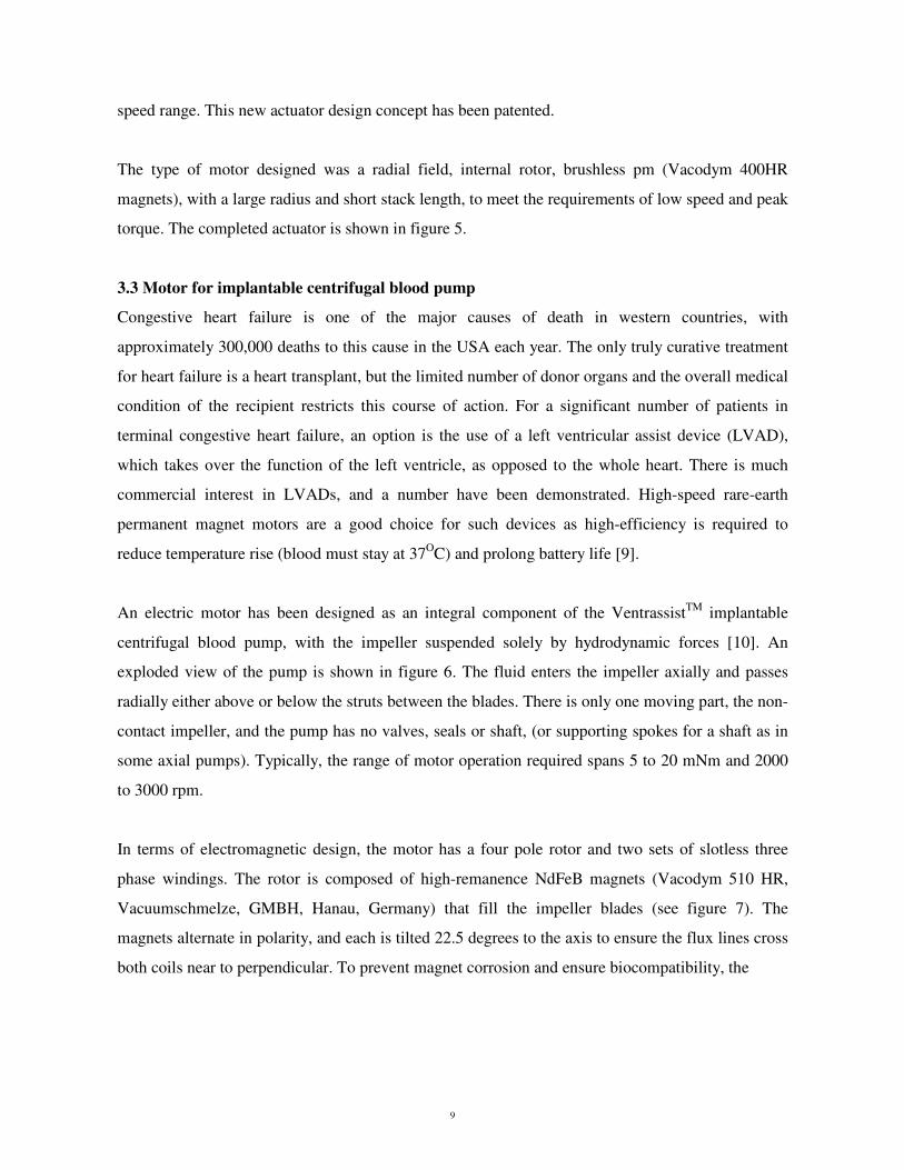
An electric motor has been designed as an integral component of the VentrassistTM implantable
centrifugal blood pump, with the impeller suspended solely by hydrodynamic forces [10]. An
exploded view of the pump is shown in figure 6. The fluid enters the impeller axially and passes
radially either above or below the struts between the blades. There is only one moving part, the non-
contact impeller, and the pump has no valves, seals or shaft, (or supporting spokes for a shaft as in
some axial pumps). Typically, the range of motor operation required spans 5 to 20 mNm and 2000
to 3000 rpm.
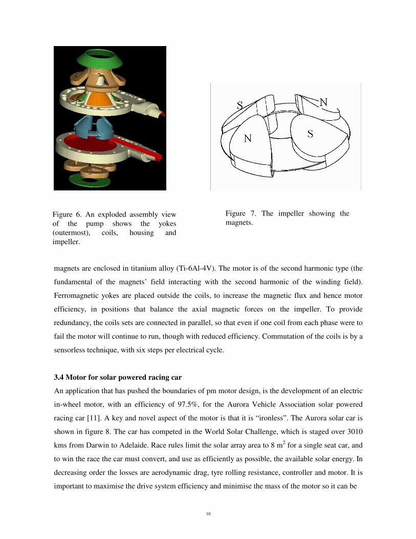
In terms of electromagnetic design, the motor has a four pole rotor and two sets of slotless three
phase windings. The rotor is composed of high-remanence NdFeB magnets (Vacodym 510 HR,
Vacuumschmelze, GMBH, Hanau, Germany) that fill the impeller blades (see figure 7). The
magnets alternate in polarity, and each is tilted 22.5 degrees to the axis to ensure the flux lines cross
both coils near to perpendicular. To prevent magnet corrosion and ensure biocompatibility, the
10
magnets are enclosed in titanium alloy (Ti-6Al-4V). The motor is of the second harmonic type (the
fundamental of the magnets’ field interacting with the second harmonic of the winding field).
Ferromagnetic yokes are placed outside the coils, to increase the magnetic flux and hence motor
efficiency, in positions that balance the axial magnetic forces on the impeller. To provide
redundancy, the coils sets are connected in parallel, so that even if one coil from each phase were to
fail the motor will continue to run, though with reduced efficiency. Commutation of the coils is by a
sensorless technique, with six steps per electrical cycle.
3.4 Motor for solar powered racing car
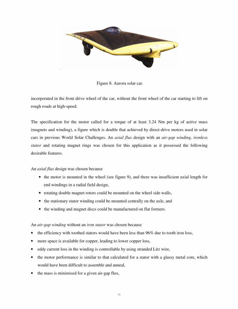
An application that has pushed the boundaries of pm motor design, is the development of an electric
in-wheel motor, with an efficiency of 97.5%, for the Aurora Vehicle Association solar powered
racing car [11]. A key and novel aspect of the motor is that it is “ironless”. The Aurora solar car is
shown in figure 8. The car has competed in the World Solar Challenge, which is staged over 3010
kms from Darwin to Adelaide. Race rules limit the solar array area to 8 m2 for a single seat car, and
to win the race the car must convert, and use as efficiently as possible, the available solar energy. In
decreasing order the losses are aerodynamic drag, tyre rolling resistance, controller and motor. It is
important to maximise the drive system efficiency and minimise the mass of the motor so it can be
Figure 6. An exploded assembly view of the pump shows the yokes (outermost), coils, housing and impeller.
Figure 7. The impeller showing the magnets.
11
incorporated in the front drive wheel of the car, without the front wheel of the car starting to lift on
rough roads at high-speed.
The specification for the motor called for a torque of at least 3.24 Nm per kg of active mass
(magnets and winding), a figure which is double that achieved by direct-drive motors used in solar
cars in previous World Solar Challenges. An axial flux design with an air-gap winding, ironless
stator and rotating magnet rings was chosen for this application as it possessed the following
desirable features.
An axial flux design was chosen because
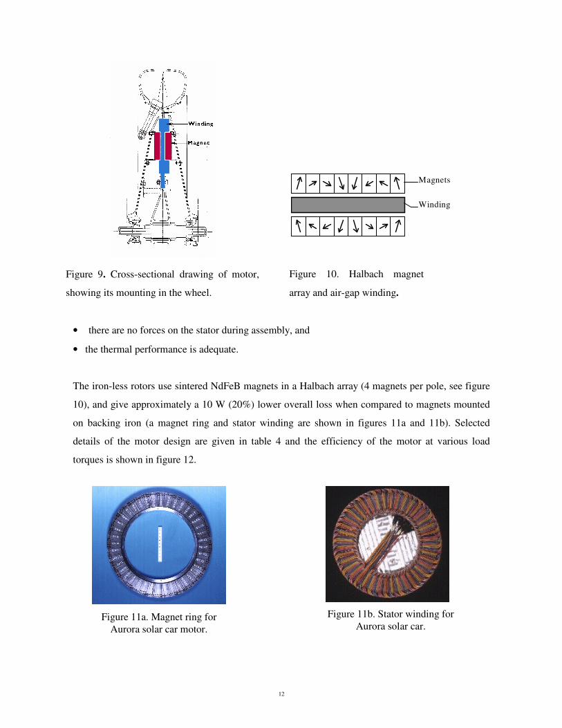
• the motor is mounted in the wheel (see figure 9), and there was insufficient axial length for
end windings in a radial field design,
• rotating double magnet rotors could be mounted on the wheel side walls,
• the stationary stator winding could be mounted centrally on the axle, and
• the winding and magnet discs could be manufactured on flat formers.
An air-gap winding without an iron stator was chosen because
• the efficiency with toothed stators would have been less than 96% due to tooth iron loss,
• more space is available for copper, leading to lower copper loss,
• eddy current loss in the winding is controllable by using stranded Litz wire,
• the motor performance is similar to that calculated for a stator with a glassy metal core, which
would have been difficult to assemble and anneal,
• the mass is minimised for a given air-gap flux,
Figure 8. Aurora solar car.
12
Magnets
Winding
• there are no forces on the stator during assembly, and
• the thermal performance is adequate.
The iron-less rotors use sintered NdFeB magnets in a Halbach array (4 magnets per pole, see figure
10), and give approximately a 10 W (20%) lower overall loss when compared to magnets mounted
on backing iron (a magnet ring and stator winding are shown in figures 11a and 11b). Selected
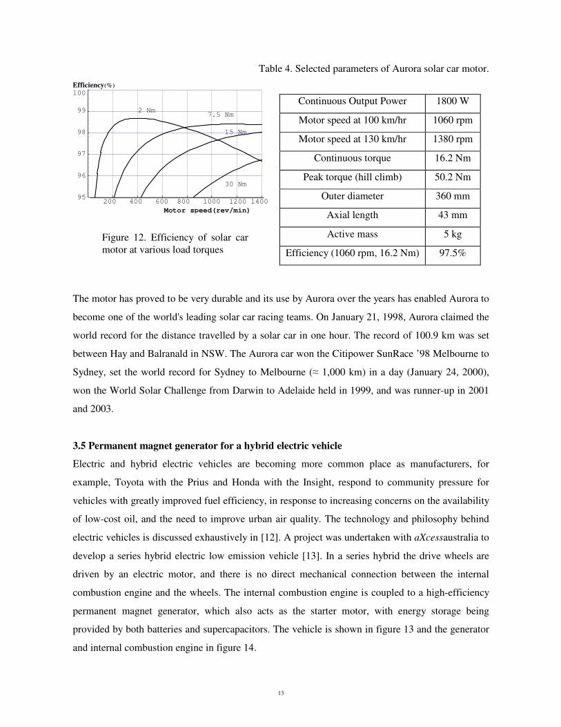
details of the motor design are given in table 4 and the efficiency of the motor at various load
torques is shown in figure 12.
Figure 10. Halbach magnet
array and air-gap winding.
Figure 9. Cross-sectional drawing of motor,
showing its mounting in the wheel.
Figure 11b. Stator winding for Aurora solar car.
Figure 11a. Magnet ring for Aurora solar car motor.
13
Table 4. Selected parameters of Aurora solar car motor. Efficiency(%)