Applied Applied Wireless Wireless Electronics Electronics Grzegorz Budzy Grzegorz Budzy ń ń L L ecture ecture 2: 2: Wireless data transfer Wireless data transfer – – proprietary proprietary solutions solutions
LLectureecture 2:2:Wireless data transfer Wireless data transfer –– proprietary proprietary solutions solutions
Plan• Advanced modulations:
– ASK, FSK, PSK
– M-PSK
– MSK
– QAM
– MIMO
• Off-the-shelf solutions
Simple solutions
Introduction
• The simplest way to transfer data from one point to another without cables is to use thesimplest modulation of Amplitude Shift Keying ASK over the allowable frequencyrange
• To achive lower suscebility to noises a Frequency Shift Keying FSK can be used
ASK
• In ASK the amplitude of an analog carrier signal varies in accordance with the bit stream (modulating signal), keeping frequency and phase constant
• Like AM, ASK is also sensitive to atmospheric noise, distortions, propagation conditions on different routes
ASK
Sourc
e: [1
]
ASK
• Because of the sharp discontinuities at the transition points the bandwidth of ASK isunnecessarily wide.
• Bandlimiting is generally introduced before transmission, in which case these discontinuities are ‘rounded off’.
• The bandlimiting may be applied to the digital message or the modulated signal itself.
ASK
• The data rate is often made a sub-multiple of the carrier frequency.
• One of the disadvantages of ASK, compared with FSK and PSK, for example, is that it has not got a constant envelope.
• This makes its processing (eg, power amplification) more difficult, since linearity becomes an important factor.
• However, it does make for ease of demodulation with an envelope detector.
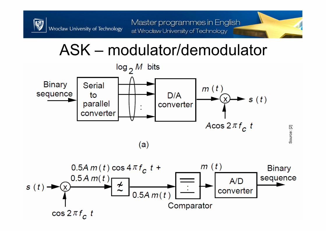
ASK – modulator/demodulator
Sourc
e: [2
]
FSK
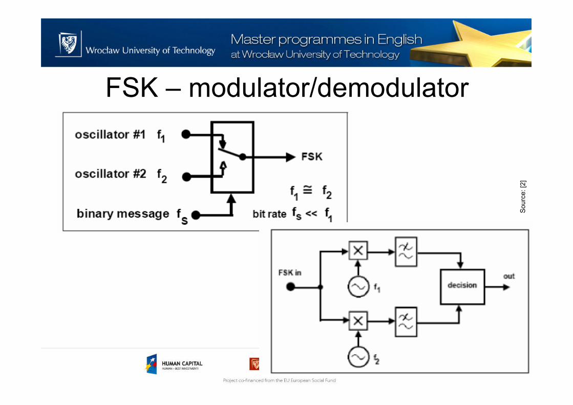
• Frequency-shift keying (FSK) is a frequency modulation scheme in which digital information is transmitted through discrete frequency changes of a carrier wave
• In the simplest version – Binary FSK – there areonly two carrier frequencies. The switching ispreformed between these two frequencies
• There are versions with more than two carrierfrequencies
FSK
Sourc
e: [1
]
FSK
• The advantage of FSK over ASK is that it rejects unwanted signals (noise) that are weaker than the desired signal
• Because a signal is always present, an automatic level control methods may be used to minimize the effects of signal fading caused by ionosphericvariations
• More difficult modulation and demodulation
FSK – modulator/demodulator
Sourc
e: [2
]
ASK/FSK receiver - features
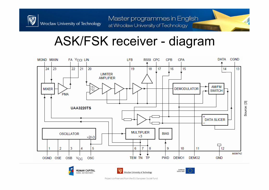
• UAA3220TS (NXP) - a fully integrated single-chip
receiver, primarily intended for use in VHF and
UHF systems
• It supports both Amplitude Shift Keying (ASK) and
Frequency Shift Keying (FSK) demodulation
• Few external low cost components and crystal
required
• Wide supply voltage range
ASK/FSK receiver - features
• Low power consumption
• Wide frequency range, 250 to 920 MHz
• High sensitivity
• IF bandwidth determined by application
• High selectivity
• Automotive temperature range
• SSOP24 package.
ASK/FSK receiver - diagram
Sourc
e: [3
]
ASK/FSK receiver – FSK reception
Sourc
e: [3
]
ASK/FSK receiver – ASK reception
Sourc
e: [3
]
BPSK
• BPSK – binary phase shift keying
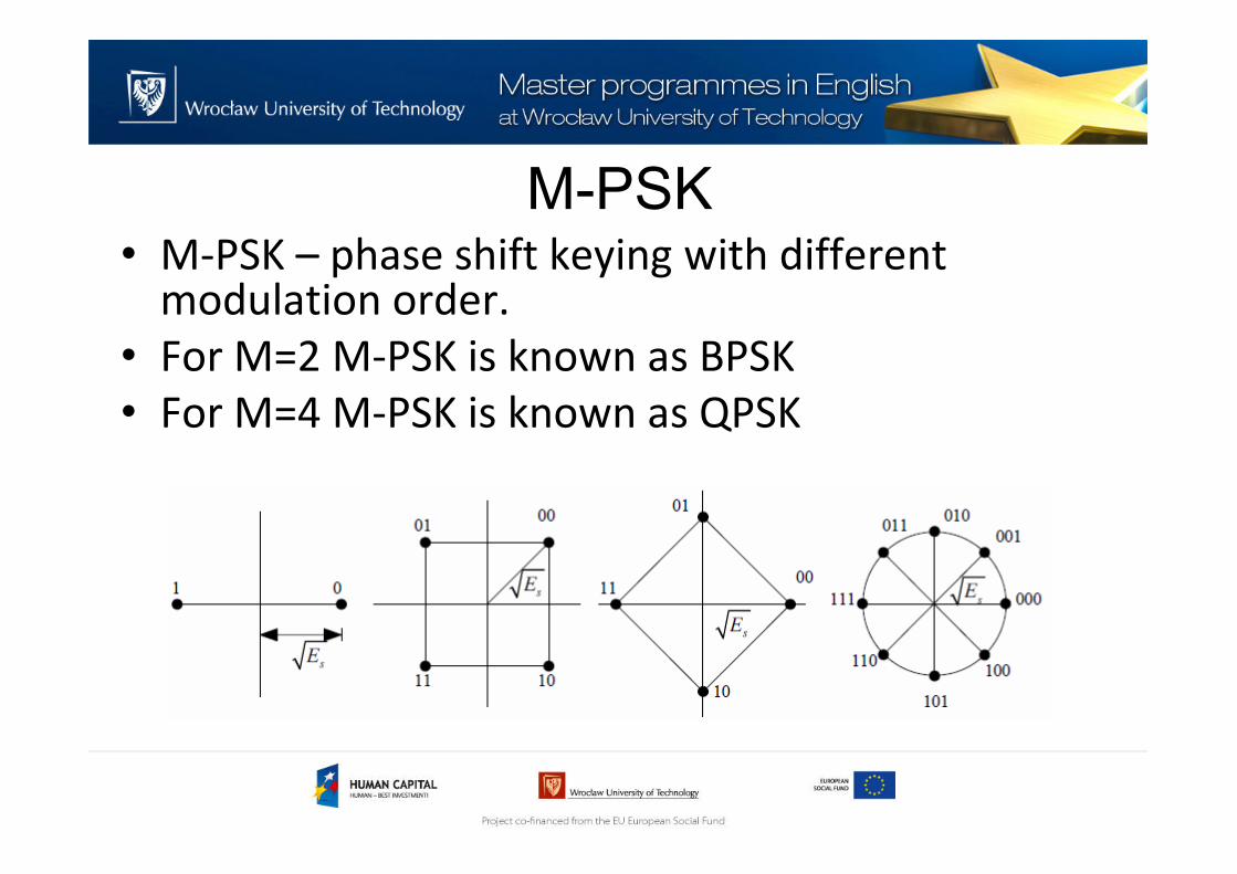
M-PSK• M-PSK – phase shift keying with different
modulation order.
• For M=2 M-PSK is known as BPSK
• For M=4 M-PSK is known as QPSK
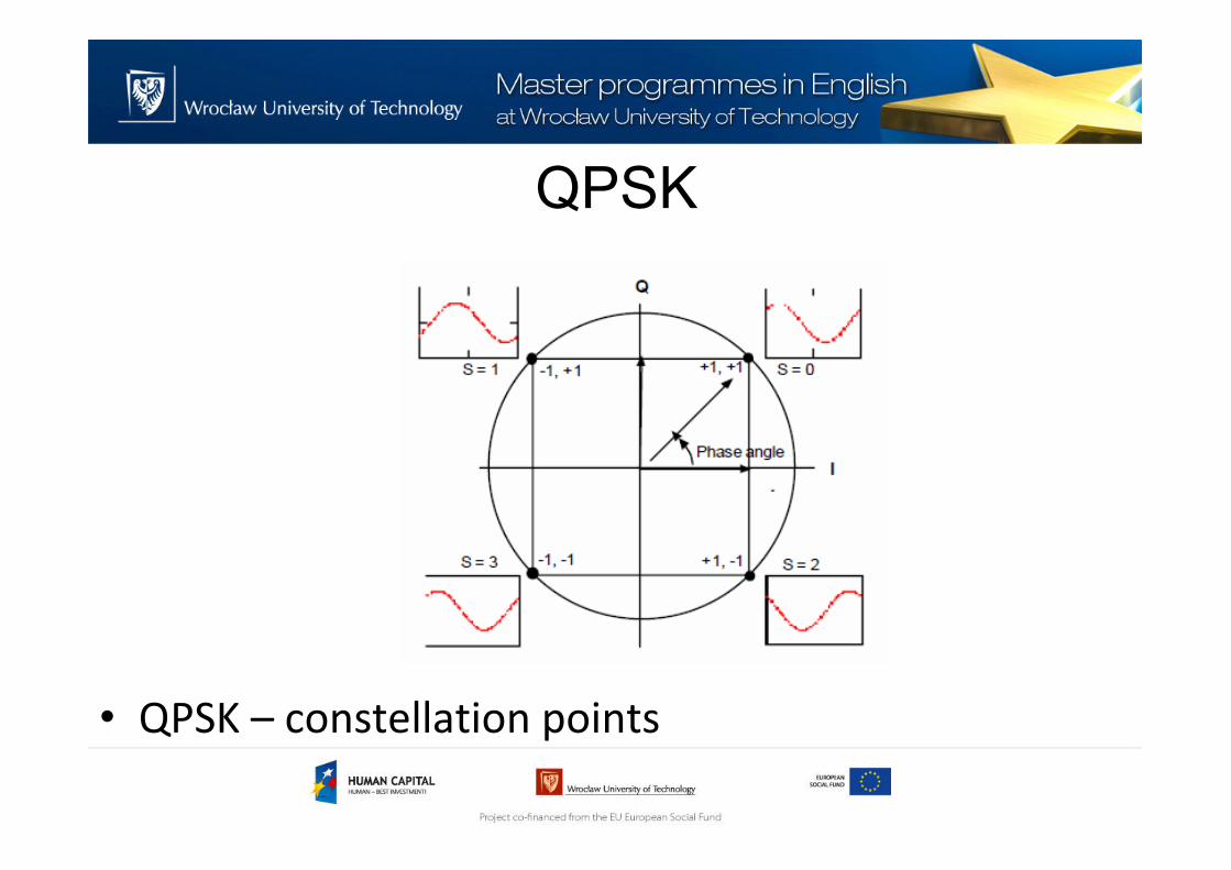
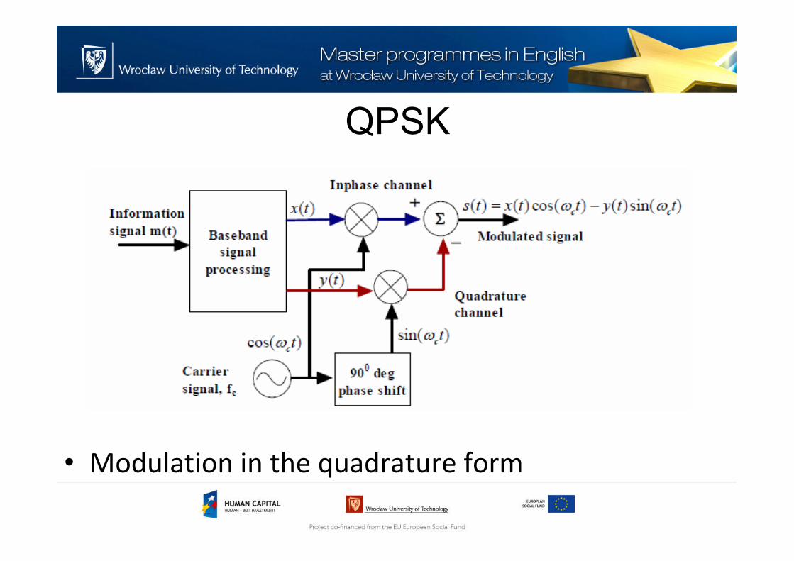
QPSK
• QPSK – constellation points
QPSK
QPSK
• Modulation in the quadrature form
QPSK
• Demodulation
OQPSK
• OQPSK – offset qudrature phase shift keying
• A variation on QPSK
• Q channel is shifted by half a symbol time sothat I and Q do not change at the same time
• OQPSK is better for high power amplifiers andcertain satellite applications – better BER!
OQPSK - modulator
OQPSK vs QPSK signals
MSK
• MSK (Minimum Shift Keying) – often classified as an FM modulation
• MSK can be derived from OQPSK – I and Q channels use square root-raised cosine pulses
GFSK
• GFSK – Gaussian Frequency Shift Keying
• FSK type modulation with gaussian type pulses(instead of binary ones)
MSK - modulator
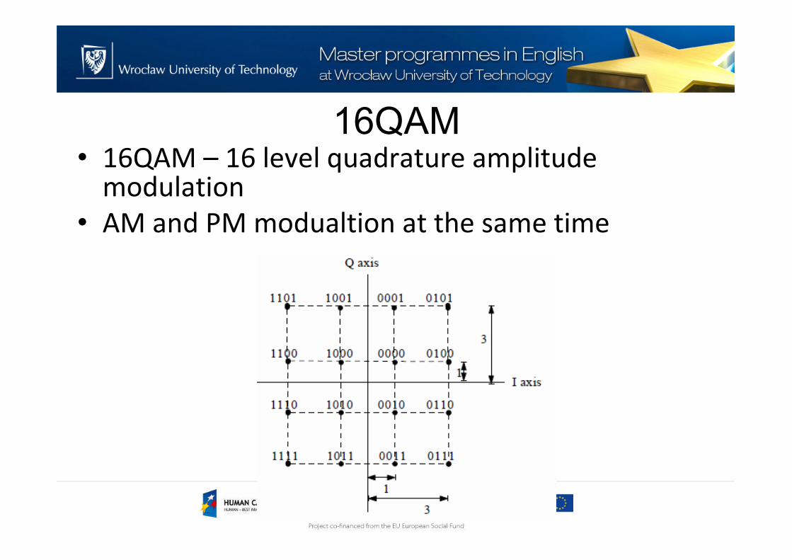
16QAM• 16QAM – 16 level quadrature amplitude
modulation
• AM and PM modualtion at the same time
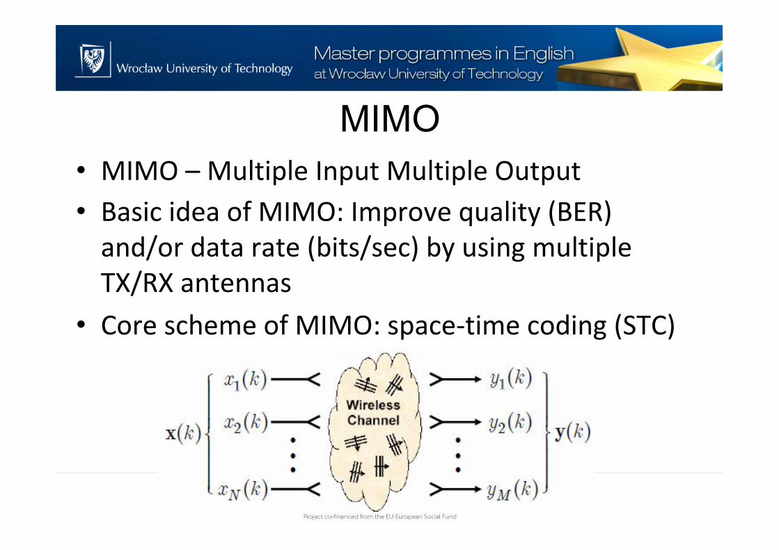
MIMO
• MIMO – Multiple Input Multiple Output
• Basic idea of MIMO: Improve quality (BER)
and/or data rate (bits/sec) by using multiple
TX/RX antennas
• Core scheme of MIMO: space-time coding (STC)
MIMO
MIMO
Information theory has shown that with
multipath propagation, multiple antennas at both
transmitter and receiver there can be establish
essentially multiple parallel channels that
operate simultaneously, on the same frequency
band at the same total radiated power
SISO
• SISO system link limitation:
• MISO system link limitation:
SISO
• SIMO system link limitation:
MIMO• MIMO system link limitation (high reliability):
• MIMO system link limitation (high speed-spatialmultiplexing):
MIMO
• MIMO technique is widely used e.g.:
– IEEE 802.11n[18]-[19]: MIMO-OFDM
• Beamforming
• Spatial diversity
• Spatial multiplexing
– IEEE 802.16 (-2004: WiMAX)[20]-[21]: MIMO-OFDM
• Beamforming
• Spatial diversity
• Spatial multiplexing
Wireless networks topologies
Wireless networks topologies• Broadcast:
– A message is sent from a device in the hope that it is received by a receiver within range. The broadcaster doesn't receive signals.
Wireless networks topologies• Mesh:
– A message can be relayed from one point in a network to any other by hopping through multiple nodes.
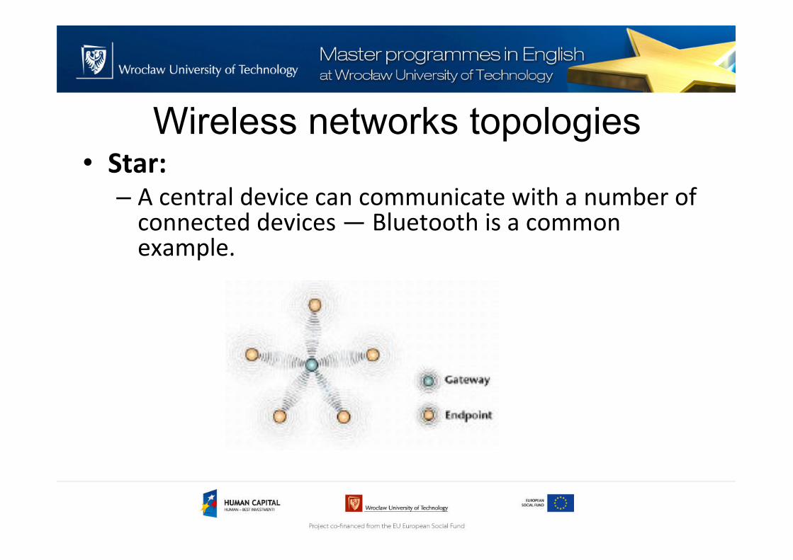
Wireless networks topologies• Star:
– A central device can communicate with a number of connected devices — Bluetooth is a common example.
Wireless networks topologies• Scanning:
– A scanning device is constantly in receive mode, waiting to pick up a signal from anything transmitting within range.
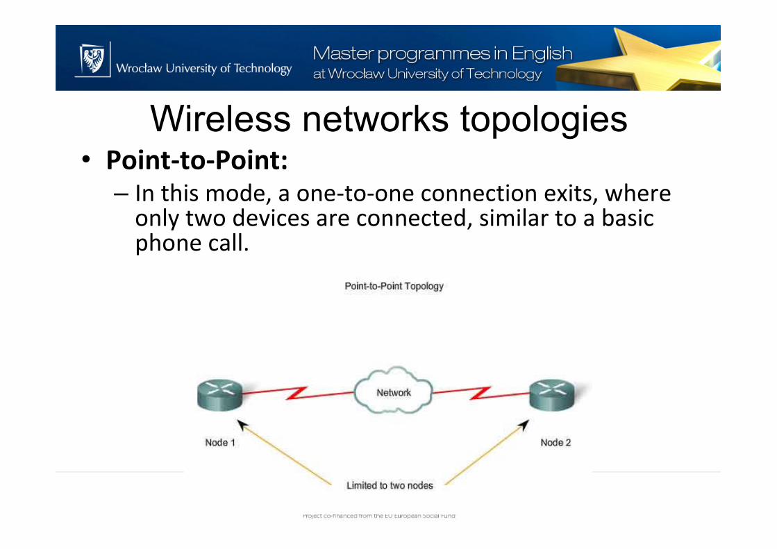
Wireless networks topologies• Point-to-Point:
– In this mode, a one-to-one connection exits, where only two devices are connected, similar to a basic phone call.
Off-the-shelf solutions
Introduction
• There exists many ready, off-the-shelf wirelesssolutions that were not standardised and can be positioned as proprietary solutions
• These solutions work in different frequencyranges and offer different properties
• Usually, though often very complicated, thesolutions are easy or very easy to use. Normallyonly couple of external components, a powersupply and an antenna is necessary
Introduction
• Main proprietary low-power wireless data transfer solutions:– Bluetooth low-energy
– ANT
– ANT+
– ZigBee RF4CE
– Nike+
– IrDA
Bluetooth Low-energy
• Adopted by the Bluetooth Special Interest Group (SIG) in 2007
• The aim of this technology is to enable power sensitive devices to be permanently connected to the Internet
• LE sensor devices are typically required to operate for many years without needing a new battery
• LE is also known as Bluetooth v4.0
Bluetooth Low-energy
• Supported network topologies:– Broadcast
– Star
– Scanning
– Point-to-Point
• Typical packet
ANT, ANT+
• ANT™ is a low-power proprietary wireless technology which operates in the 2.4 GHz spectrum
• It was established in 2004 by the sensor company Dynastream
• The ANT transceiver device is treated as a black box and shouldn't require much design effort to implement into a network
• Typically used in sports and fitness sensors to communicate with a display unit
ANT, ANT+
• ANT+™ has taken the ANT protocol and made the devices interoperable in a managed network
• Similar to BLE, ANT devices may operate for years on a coin cell
• Supported network topologies:– Broadcast
– Mesh
– Star
– Scanning
– Point-to-Point
ZigBee RF4CE
• Radio Frequency for Consumer Electronics (RF4CE) is based on ZigBee and was standardized in 2009
• Two silicon vendors support RF4CE: TI and Freescale
• RF4CE's intended use is as a device remote control system, for example for television set-top boxes
• Similar to ZigBee
ZigBee RF4CE
• Supported network topologies:– Mesh
– Star
– Scanning
– Point-to-Point
Nike+
• Nike+® is a proprietary wireless technology developed by Nike and Apple to allow users to monitor their activity levels while exercising
• Its power consumption is relatively high
• It will only work between Nike and Apple devices
• Supported network topologies:– Scanning
– Point-to-Point
IrDA• Wireless data transfer technology basing on
optical transfer of data
• IrDA (Infrared Data Association) has recently announced an ultra-high-speed connectivity version, yielding 1 Gbps
• The main problem is with the short range –counted in centimeters
• IrDA® is also not particularly power efficient (power per bit) when compared against radio technologies
• Only Point-to-Point transfer supported
Comparison
• Range:
– NFC – 5 cm
– IrDA – 10 cm
– Nike+ – 10 m
– ANT(+) – 30 m
– RF4CE based on ZigBee – 100 m
– Wi-Fi – 150 m
– LE – 280 m
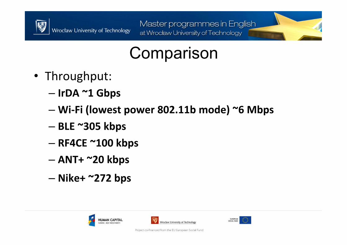
Comparison
• Throughput:
– IrDA ~1 Gbps
– Wi-Fi (lowest power 802.11b mode) ~6 Mbps
– BLE ~305 kbps
– RF4CE ~100 kbps
– ANT+ ~20 kbps
– Nike+ ~272 bps
Comparison
• Latency:
– ANT ~zero
– Wi-Fi ~1.5 ms
– LE ~2.5 ms
– RF4CE ~20 ms
– IrDA ~25 ms
– Nike+ ~1 second
Comparison
• Peak power consumption:
– IrDA peak current draw ~ 10.2 mA
– Nike+ peak current draw ~ 12.3 mA
– LE peak current draw ~ 12.5 mA
– ANT peak current draw ~ 17 mA
– RF4CE peak current draw ~ 40 mA
– Wi-Fi peak current draw ~ 116 mA (@1.8 V)
Examples
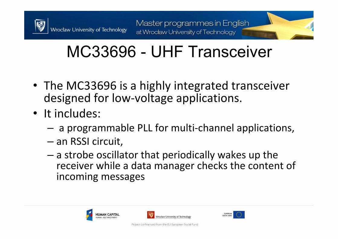
MC33696 - UHF Transceiver
• The MC33696 is a highly integrated transceiverdesigned for low-voltage applications.
• It includes:– a programmable PLL for multi-channel applications,
– an RSSI circuit,
– a strobe oscillator that periodically wakes up the receiver while a data manager checks the content of incoming messages
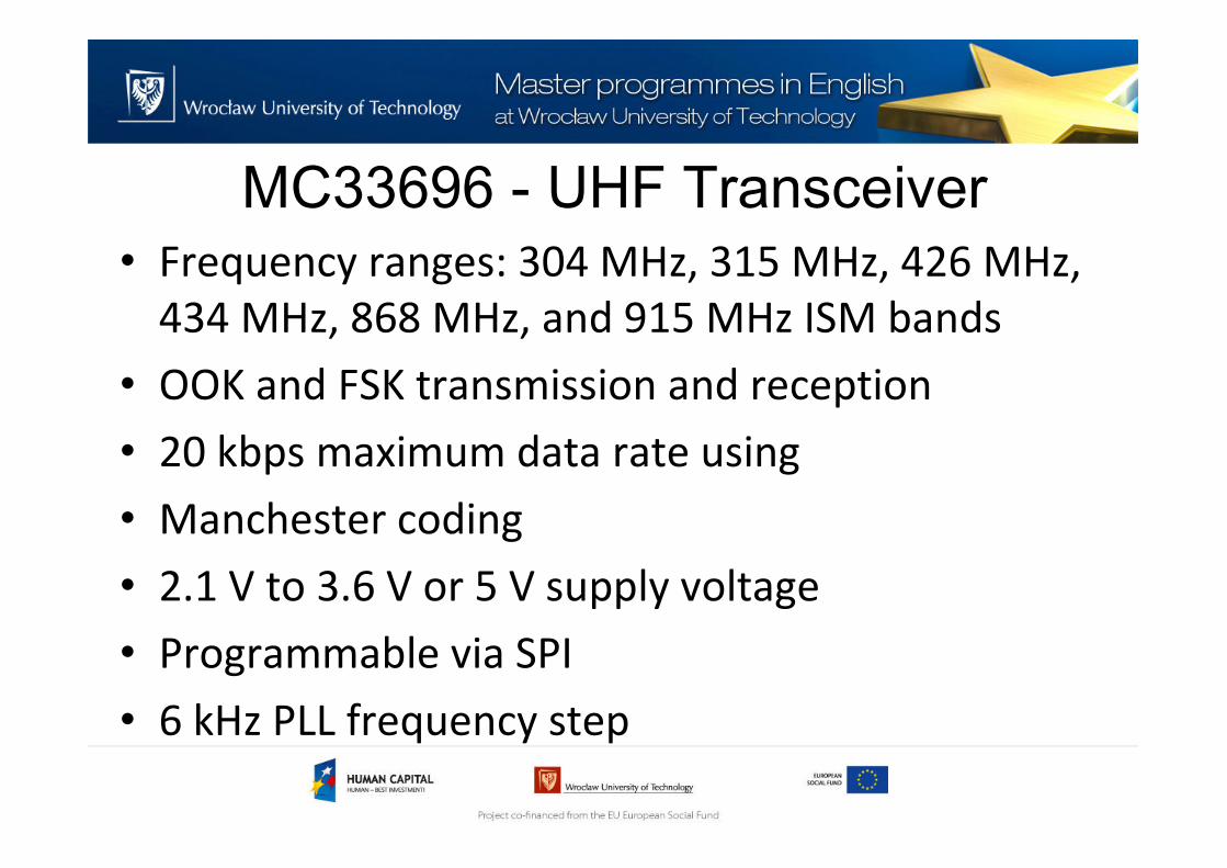
MC33696 - UHF Transceiver
• Frequency ranges: 304 MHz, 315 MHz, 426 MHz,
434 MHz, 868 MHz, and 915 MHz ISM bands
• OOK and FSK transmission and reception
• 20 kbps maximum data rate using
• Manchester coding
• 2.1 V to 3.6 V or 5 V supply voltage
• Programmable via SPI
• 6 kHz PLL frequency step
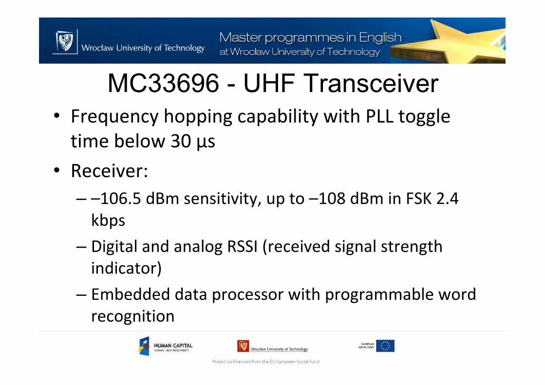
MC33696 - UHF Transceiver
• Frequency hopping capability with PLL toggle
time below 30 μs
• Receiver:
– –106.5 dBm sensitivity, up to –108 dBm in FSK 2.4
kbps
– Digital and analog RSSI (received signal strength
indicator)
– Embedded data processor with programmable word
recognition
MC33696 - UHF Transceiver• Frame format:
• Preamble format:
Sourc
e: [4
]
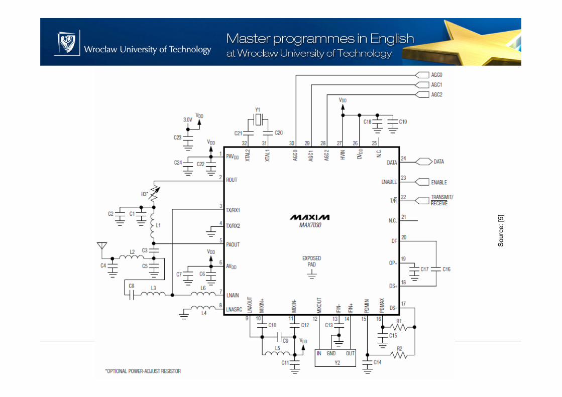
MAX7030 - ASK Transceiver
• The MAX7030 is crystal-based, fractional-N
transceiver designed to transmit and receive
ASK/OOK data at factory-preset carrier
frequencies
• The MAX7030 features separate transmit and
receive pins and provides an internal RF switch
that can be used to connect the transmit and
receive pins to a common antenna
MAX7030 - ASK Transceiver
• Frequencies: 315MHz, 345MHz, or 433.92MHz
• Data rates: 33kbps (Manchester encoded) or
66kbps (NRZ encoded)
• Typical output power of +10dBm
• Typical receiver sensitivity of -114dBm
• ASK/OOK Modulation
• Integrated Transmit and Receive PLL, VCO, and
Loop Filter
MAX7030 - ASK Transceiver
Sourc
e: [5
]
MAX7030 - ASK Transceiver
Sourc
e: [5
]
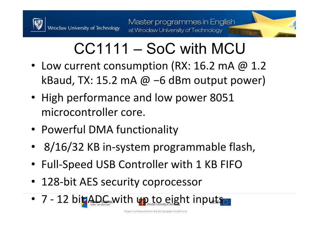
CC1111 – SoC with MCU
• CC1111 is a System-On-Chip that combines an
8051 MCU and RF part
• Frequency range: 300 - 348 MHz, 391 – 464 MHz
and 782 - 928 MHz
• Programmable data rate up to 500 kBaud
• Programmable output power up to 10 dBm for
all supported frequencies
• High sensitivity (−110 dBm at 1.2 kBaud)
CC1111 – SoC with MCU• Low current consumption (RX: 16.2 mA @ 1.2
kBaud, TX: 15.2 mA @ −6 dBm output power)
• High performance and low power 8051
microcontroller core.
• Powerful DMA functionality
• 8/16/32 KB in-system programmable flash,
• Full-Speed USB Controller with 1 KB FIFO
• 128-bit AES security coprocessor
• 7 - 12 bit ADC with up to eight inputs
Sourc
e: [6
]
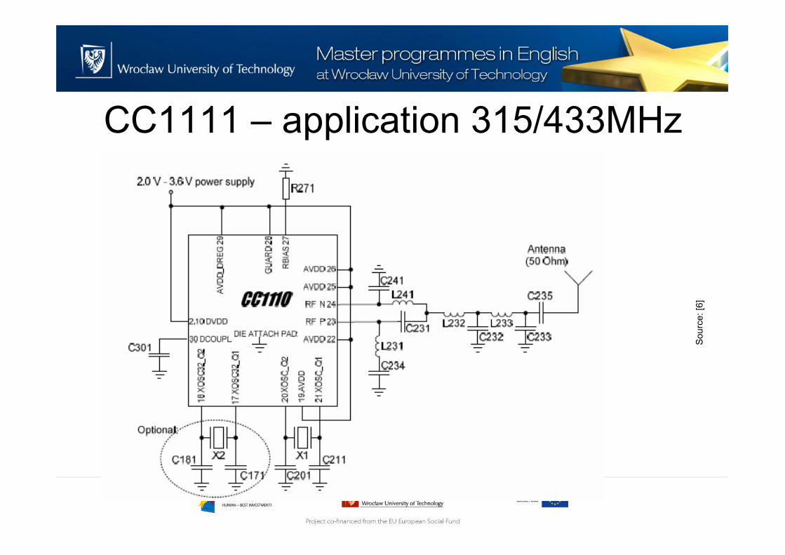
CC1111 – application 315/433MHz
Sourc
e: [6
]
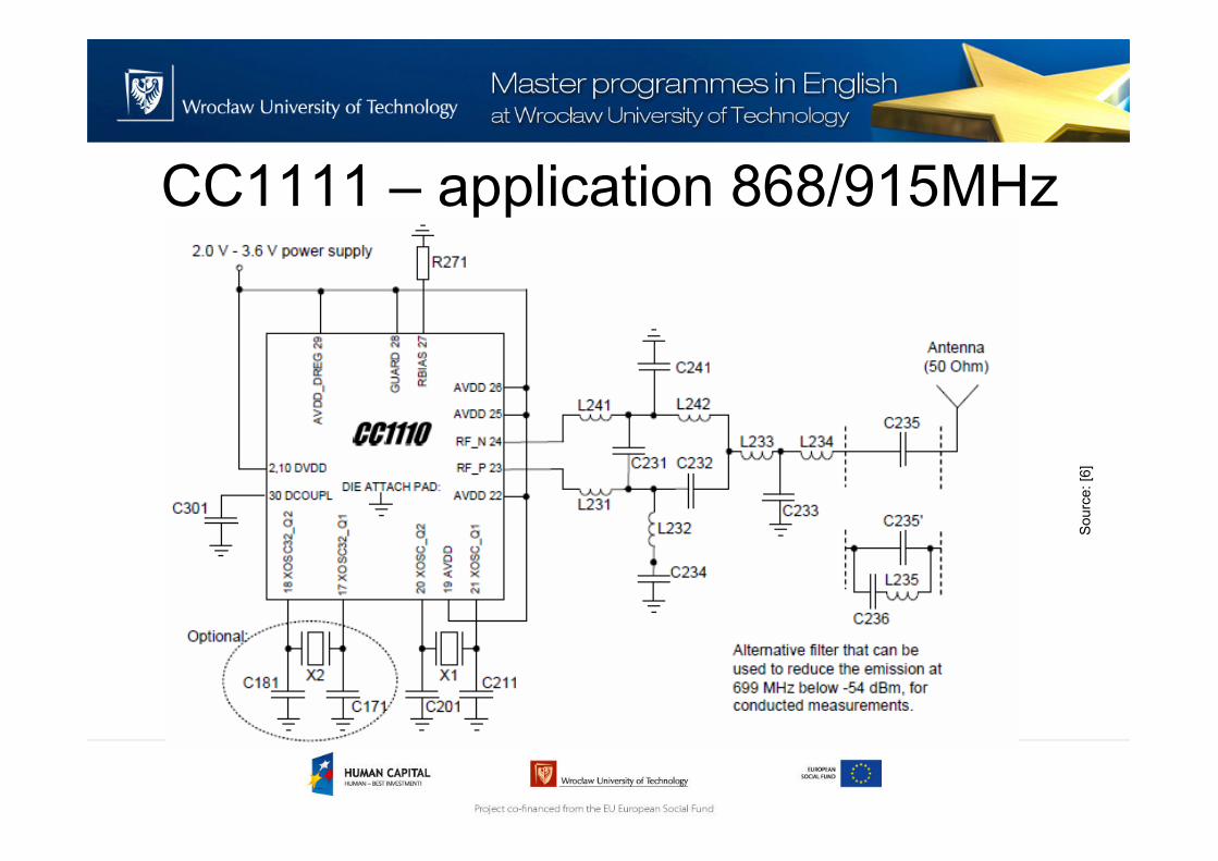
CC1111 – application 868/915MHz
Sourc
e: [6
]
Thank you for your attention
References[1] „Amplitude Shift Keying & Frequency Shift Keying”,