APPROVAL ISSUE Module 234-7 Course 234 _ Turbine and Auxiliaries - Module Seven NOTES & REFERENCES THE TURBINE GOVERNING SYSTEM OBJECTIVES: After completing this module you will be able to: 7.1 Given a simplified block diagram of a typical turbine governing sys- tem, state the function and describe the operation of each of the fol- lowing components: a) Load limiter; b) Unloaders. 7.2 Given a simplified diagram of a typical hydraulic actuator of a tur- bine control valve, describe: a) The actuator operation in response to: i) A control signal; il) A trip signal; iii) A test signal; b) Its major fail-safe feature. 7.3 a) Describe three adverse consequences/operating concerns caused by impurities in the hydrauilc fluid used in a turbine governing system. b) Describe two ways of maintaining its proper purity. 7.4 Given a simplified block diagram of a typical turbine governing sys- tem, describe the system operation: a) During turbine mnup and power manoeuvres; b) During unit steady power operation; c) In response to: i) A turbine trip; il) A load rejection; iii) A reactor trip. ¢Pages 3-4 ¢Pages 4-5 ¢Pages 7-8 ¢Pages 8-9 ¢Page9 ¢Page 6 ¢Page10 ¢Pagell ¢ Pages 11-13 ¢Page13 ¢Page14 ¢Pages 14-15 ¢Page15 Page 1
Transcript
APPROVAL ISSUE
Module 234-7
Course 234 _ Turbine and Auxiliaries - Module Seven
NOTES & REFERENCES
THE TURBINE GOVERNINGSYSTEM
OBJECTIVES:After completing this module you will be able to:
7.1 Given a simplified block diagram of a typical turbine governing system, state the function and describe the operation of each of the following components:
a) Load limiter;
b) Unloaders.
7.2 Given a simplified diagram of a typical hydraulic actuator of a turbine control valve, describe:
a) The actuator operation in response to:
i) A control signal;
il) A trip signal;
iii) A test signal;
b) Its major fail-safe feature.
7.3 a) Describe three adverse consequences/operating concerns causedby impurities in the hydrauilc fluid used in a turbine governingsystem.
b) Describe two ways of maintaining its proper purity.
7.4 Given a simplified block diagram of a typical turbine governing system, describe the system operation:
State a typical IlUlge of nmback rates expressed as a percentage of full power per second.
State the difference between latched and unlatched ronbacks.
b) List five typical operating events initiating a turbine nmback andfor each of them:
i) Explain the purpose of the turbine nmback;
ti) State the type of the nmback.
List two operating conditions during which turbine speed canreach the overspeed trip level.
State three factors that contribute to enhanced turbine overspeedprotection by the emergency overspeed governor.
Describe the principle of operation of a typical emergency overspeed governor.
List two types of tests of the governor.
Explain how emergency overspeed can be simulated while testing the governor.
State the mandatory action that must be taken if the governorfalls an actual overspeed test
* * *
INSTRUCTIONAL TEXT
INTRODUCTIONIn the previous turbine courses which you have taken so far, the functionsand the structure of the turbine governing system are described. Based onthis general knowledge, this module discusses the following topics:
- Functions of the system components;- Hydraulic actuation of turbine stearn valves;- Operation of the system during various unit operating states;- Emergency overspeed governor.
The turbine governing systems installed in different stations differ significantly from one another. It is not the intent of this module to cover thesedifferences. Instead., a more general approach, with focus on common features, is taken. However, an inherent result of this generalization is that the
technical terminology (eg. the names of system components) used throughout the module may differ somewhat from that used. in your station.
Similar to the preceding modules, a simplified pullout diagram of the systemis attached at the end of the module, for easy reference.
NOTES & REFERENCE~
FUNCTIONS OF THE SYSTEMCOMPONENTS
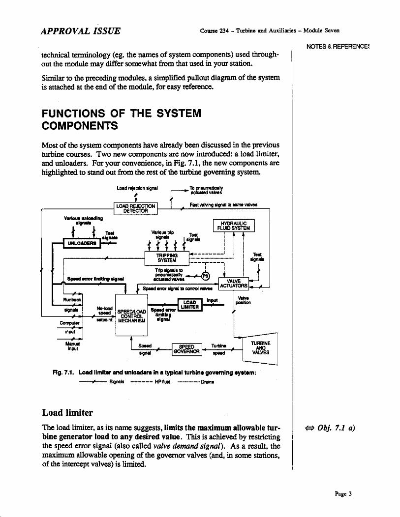
Most of the system components have already been discussed in the previousturbine courses. Two new components are now introduced: a load limiter,and unloaders. For your convenience, in Fig. 7.1, the new components arehighlighted to stand out from the rest of the turbine governing system.
Fig. 7.1. Load limiter and unloaderilin a typICilI turbine gOQl'nlng ey..m:,.. Signal. ------ HP ftuid _- DraIn,
Load limiter
The load limiter, as its name suggests,limits the maximum allowable turbine generator load to any desired value. This is achieved by restrictingthe speed error signal (also called valve demtlnd signal). As a result, themaximum allowable opening of the governor valves (and, in some stations,of the inten:ept valves) is limited.
• The purpose of turbineunloading in these circumstances wu coveredin modules 234·3 and234·.5.
• More infonnation aboutturbine runbacks is provid.ed later in this module.
Pue4
Note that to limit turbine load, it is not enough to limit the no-loadspeed setpolnt to the speed/load control mechanism. After &II, thespeed error signal depends &Iso on turbine speed. The latter is locked to thegrid frequency as .long as the generator is synchronized. Therefore. _a reduction in the grid frequency (due to a grid upset) would increase the speederror signal. thereby demanding increased valve opening. If the valves arenot already fully open. execution of this demand would increase turbinegenerator output. perhaps above the existing load limit. To prevent this.the load limiter restricts the speed error signal. In effect, the v&lveopening - and hence, turbine load - are limited regardless of turbine speed.Note that the load limiter does not interfere with the notm&! control action aslong as the speed error sign&l does not demand a turbine load above thelimit
During normal unit operation, the load limiter setpoint is typic&lly keptsomewhat above full turbine load. This prevents the load limiter frotn interfering with operation of the rest of the turbine governing syst~m. However.the load limiter se!point is reduced appropriately when some operation&lproblem (eg. loss ofreheating) forces unit derating.
Unloaders
A typical turbine governing system has two unloaders - one activated bylow condenser vacuum. and the other by low boiler pressure. The activated unloader acts similarly to the load limiter, ie. it restricts the v&lve demand signal, thereby limiting the steam flow, and hence, turbine generatorload. The lower the condenser vacuum or boiler pressure, the largerthe load restriction. If the aetualload is below the restriction. the unit operation is not affected. Otherwise, the load is reduced as demanded by theactive unloader'. Note that unloading can be performed very quickly hecause the unloading signal is supplied directly to turbine v&lves, overridingthe no-load speed setpoint
Typically. the maximum turbine unloading is not continued to zero load,but ends at about 10·30% FP, depending on the station. By doing so,prolonged turbine operation with a small or no steam flow is avoided. Youwill recall that such operation promotes some operational problems in theturbine last stage(s).
When turbine load is being reduced by either unloader, the no-load speedsetpoint to the speed/1oad control mechanism is &Iso being reduced to thev&lue corresponding to the aetu&l reduced turbine load. This action - typic&lly referred to as fast turblM TUlIback' - is much slower than unloading.In other words, turbine runback, at least in this particular case, follows rather than causes a reduction in turbine load.
The actual purpose of a turbine runback under these circumstances is toprevent turbine load cycling. Here is how it could happen if turbine un-
loading were not accompanied with the appropriate ronback. A reduction inthe turbine steam flow brought about by turbine unloading would reduce thecondenser thermal load and the boller thermal oUtpUL As a result. the unloading parameter (low condenser vacuum or boiler pressure. as the casemay be) may begin to return to its normal range. thereby redUcing the loadrestriction imposed by the activated unloader. 'This would cause an increasein turbine load as demanded by the unchanged no-load speed setpoint. Theturbine steam flow would increase, causing unloading to recur again. Andso. cycles of uriloading and loading would follow.
SUMMARY OF THE KEY CONCEPTS• The load limiter restricts the maximum allowable turbine generator load.
This is achieved by restricting the speed enor signal supplied 10 thevalves controlling the tmbine steam flow.
• The low condenser vacuum unload.er and the low boiler pressure 00
loader can restrict the turbine load. The lower the condenser vacuum orthe boiler pressure. the larger the load restriction. If the actual turbineload exceeds the limit, turbine unloading occurs until the restriction ismeL In addition. the no-load speed setpoint is run back until it matchesthe unloading signal. The runback is performed 10 prevent turbine loadcycling.
You can now do assignment questions 1..2.
HYDRAULIC ACTUATION OF TURBINE STEAMVALVESIn this section, two topics are covered:
Operation of the typical hydraulic actuator of a turbine steam valve and;- Purity of the hydraulic fluid used for valve actuation.
Hydraulic actuators
The actuator of a large turbine steam valve must generate large forces thatare required 10 overcome forces exerted by the steam flow and friction in thevalve stem seal. Valve positioning must be accurate for adequate controlof turbine generator load (when syncbronized) and speed (during runup andsyncbronization). And proper equipment protection requires fast and reliable action of the valves during emergency conditions. Compared with other types of valve aetualors (eg. mechanical or electrical). hydraulic actuatorsmeet the above requirements best. This is why they are commonly used toeperate steam turbine valves.
Many design variations of hydraulic actuators for large turbine steam valvesare used in different CANDU stations. Even in the same station,.differentvalves have actuators of different design. The infonnation presented in thismodule does not refer to any particular design, nor does it attempt to coverthe design variations. Inste'ad, one of many possible ways of accomplishing the major required features of any actuator is described. The more general case of actuation of a control valve, as opposed to an on-off stop valve,is discussed.
In addition to the three actuator features stated above, two others are required as well Namely, any valve actuator must:
- Fail in the valve sare position and;- Allow on-power valve tests.
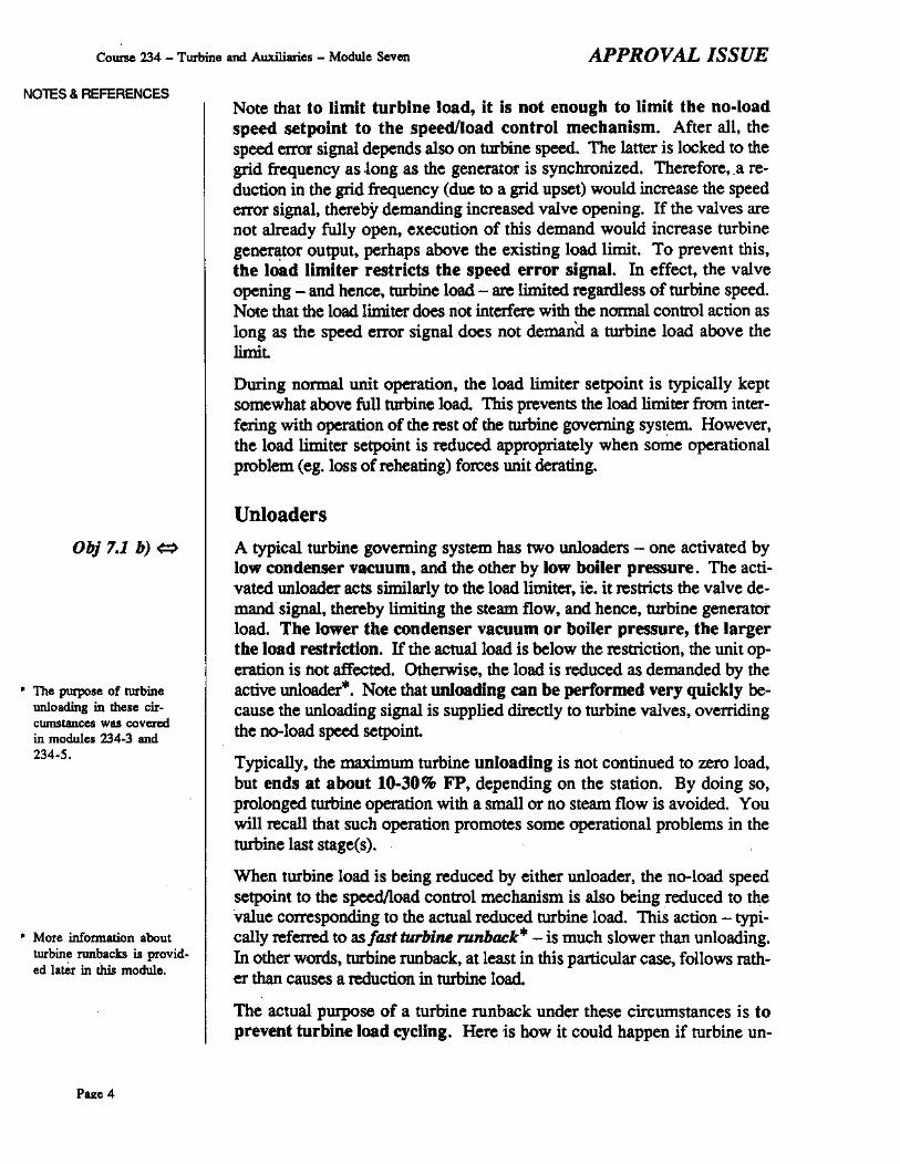
How all these requirements can be met is illusttated in Fig. 7.2 a) through d)where new details are gradually introduced to facilitate understanding of theactuator operation. In each of these drawings, the newly introduced detailsare highlighted for your convenience.
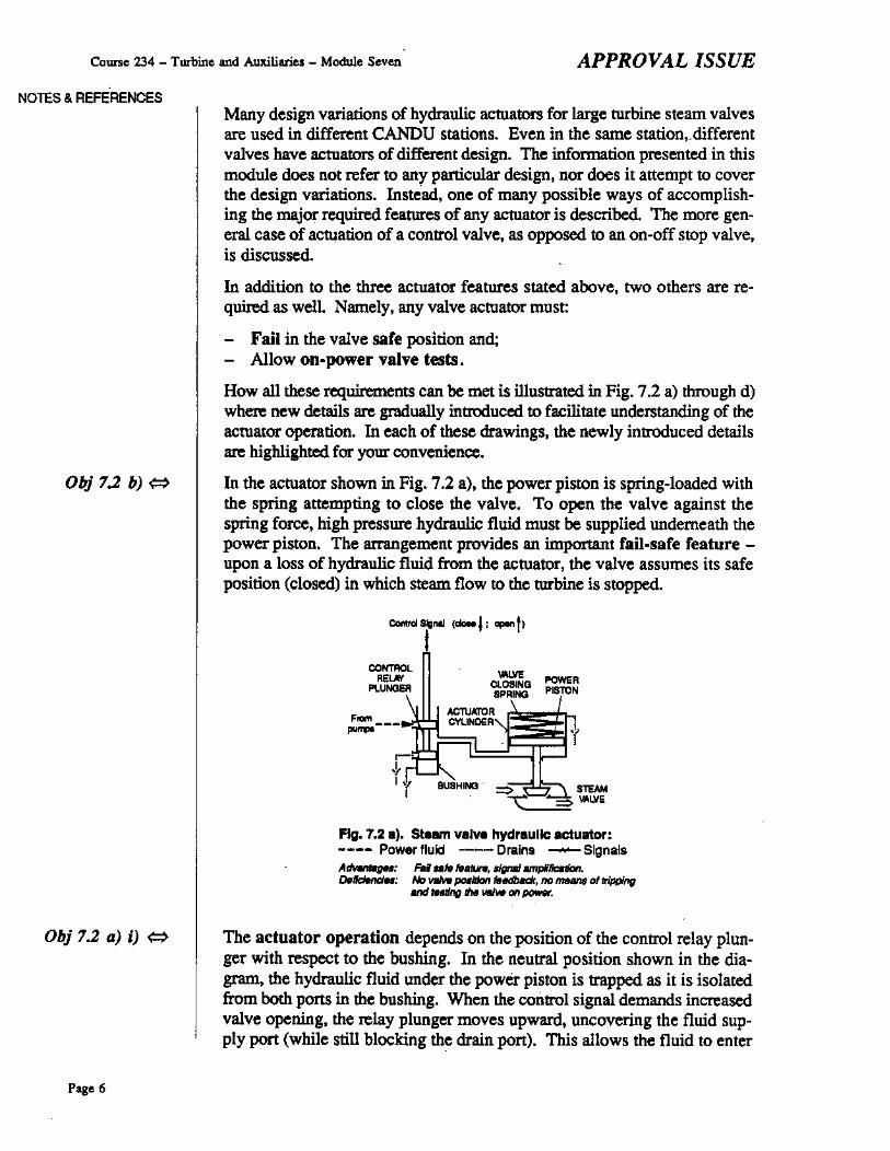
In the actuator shown in Fig. 7.2 a), the power piston is spring-loaded withthe spring attempting to close the valve. To open the valve against thespring force, high pressure hydraulic fluid must be supplied underneath thepower piston. The arrangement provides an imponant fail-safe feature upon a loss of hydraulic fluid from the actuator, the valve assumes its safeposition (closed) in which steam flow to the turbine is stopped.
CO"""',"<eM
PlUNGEJl
=---......
CLOSINGSPRING
..,mu",,,CYLINDER
POWE'PISTON
Obj 7.2 a) i) ~
Page 6
Fig. 7.2 .). Steam velve hydraulic actuator:---- Power fluid --Drains - SignalsAdvMMgM: Fdate fHlLh, slgne IIIrIpIbtion.o.~: No vaMr pcMiJJon tefldbat:k, no meant 01 tripping
Md luling thtIlo'lIfw on IXJ'N«.
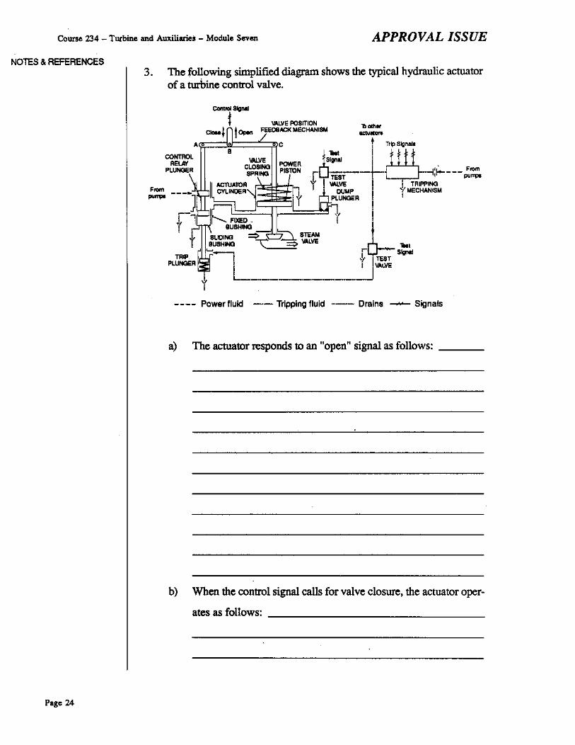
The actuator operation depends on the position of the control relay plunger with respect to the bushing. In the neuttal position shown in the diagram, the hydraulic fluid under the power piston is ttapped as it is isolatedfrom both ports in the bushing. When the control signal demands increasedvalve opening, the relay plunger moves upward, uncovering the fluid supply port (while still blocking the drain port). This allows the fluid to enter
the actuator cylinder where it drives the power piston upward against thevalve closing spring. Thus, the valve opening is increased. .
When a "close" control signal is applied, the relay plunger moves downward, uncovering the drain pan (of course, the fluid supply port remainsblocked). The fluid In the actuator cylinder is pushed out by the valve closing spring, and the valve closes.
Note tluit this actuator is a powetful amplifier of the conttol signal. Moving'the conttol relay plunger does not require a large force and displacement duete the small size of the relay. The power piston, however. is much larger.Its size, combined with the high pressure of the hydraulic fluid, allows theactuator to develop very large forces adequate to operate a large steamvalve.
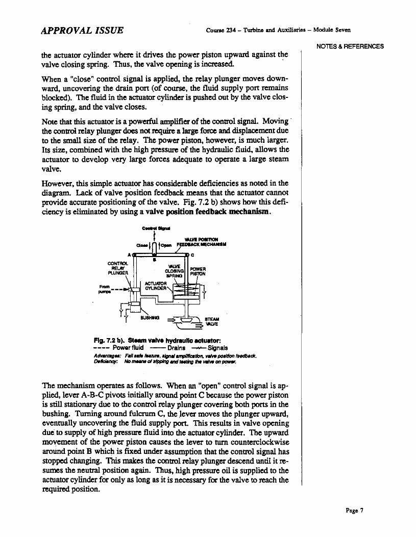
However, this simple actuator has considerable deficiencies as noted in thediagram. Lack of valve position feedback means that the actuator cannotprovide accurate positioning of the valve. Fig. 7.2 b) shows how this deficiency is eliminated by using a valve position feedbackmec:hanism.
The mechanism operates as follows. When an "open" control signal is applied,lever A-B-C pivots initially around point C because the power pistonis still stationary due to the conttol relay plunger covering both ports in thebushing. Turning around fulcrum C, the .lever moves the plunger upward,eventually uncovering the fluid supply port. This results in valve openingdue to supply of high pressure fluid into the actuator cylinder. The upwardmovement of the power piston causes the lever to turn counterclockwisearound point B which is fixed under assumption that the conttol signal hasstopped changing. This makes the conttol relay plunger descend until it resumes the neutral position again. Thus, high pressure oil is supplied to theactuator cylinder for only as long as it is necessary for the valve to reach therequired position.
The opposite processes occur when a "close" control signal is applied. Thistime, the drain port in the bushing is teniporarily uncovered until the valveposition feedback mechanism returns the control relay plunger to its neutralposition when the demanded valve position is reached.
How the valve can be tripped independently from the control signal isshown in Fig. 7.2 c). Valve tripping is initiated by the tripping mechanism.This mechanism does not belong to any panicular actuator, but is a separatepart of the turbine governing system. When a turbine trip signal is applied,the mechanism dumps the tripping fluid (normally pressurized) to drains.The rate of drainage considerably exceeds the rate of the fluid supply (by thepumps) which is restricted by an orifice in the supply piping. Consequently, the tripping fluid pressure drops quickly.
two~ IM8M 01 tripping II» vaMt.o.flcIMt;y: No mtIIIinB oftftdng II» vlIIw an poww.
This results in two independent actions. First, the spring loaded tripplunger rises, driving the sliding bushing upward (note that in the two previous drawings, the bushing was assumed to stay in a fixed position). As aresult, the drain port in the bushing is uncovered, regardless of the positionof the control relay plunger, ie. regardless of the control signal. Thevalve closing spring now pushes the fluid out of the actuator cylinder. tripping the valve closed.
At the same time, the dump plunger rises, too. The plunger is hydraulicallyunba1anced as its upper surface is larger than the bottom one. Therefore, itis pressed against its seat as long as the tripping fluid is at full pressure.When the pressure is lost on a turbine trip, the plunger is raised by the highpressure fluid in the actuator cylinder. This opens another drainage path forthis fluid.
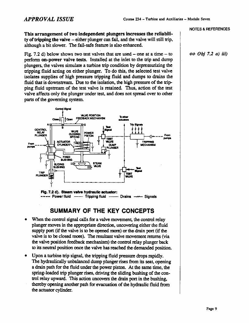
This arrangement or two independent plungers increases the reliabili..ty of tripping tbe valve - either plunger can fail, and the valve will still trip,although a bit slower. The fail-safe feature is also enhanced.
Fig. 7.2 d) below shows two test valves that are used - one at a time - toperfonn on-power valve tests. Installed at the inlet to the trip and dumpplungers, the valves simulate a turbine trip condition by depressurizing thetripping fluid acting on either plunger. To do this, the selected test valveisolates supplies of high pressure tripping fluid and dumps to drains thefluid that is downstream. Due to the isolation, the high pressure of the tripping fluid upstream of the test valve is retained Thus, action of the testvalve affects only the plunger under test, and does not spread over to otherparts of the governing system.
SUMMARY OF THE KEY CONCEPTS• When the control signal calls for a valve movement, the control relay
plunger moves in the appropriate direction, uncovering either the fluidsupply port (if the valve is to be opened more) or the drain port (if thevalve is to be closed more). The resultant valve movement returns (viathe valve position feedback mechanism) the control relay plunger backto its neutral position once the valve has reached the demanded position.
• Upon a turbine trip signal, the tripping fluid pressure drops rapidly.The hydraulically unbalanced dump plunger rises from its seat, openinga drain path for the fluid under the power piston. At the same time, thespring-loaded trip plunger rises, driving the sliding bushing of the control relay upward. This action uncovers the drain port in the busbing,thereby opening another path for evacuation of the hydraulic fluid fromthe actuator cylinder.
.. Of the order of • few mi·crons (1 micron : .001millimeter).
Page 10
• On-power tests of the dump and trip plungers are perfonned using testvalves which dump to drain the tripping fluid supplied to either plungerwhile maintaining essentially normal fluid pressure elsewhere.
Hydraulic fluid purity
In modern turbine governing systems, the hydraulic fluid pressure is keptvery high (in the order of 10 MPa) in order to reduce the size of turbinevalve actuators. This makes the system respond faster to emergency conditions (turbine trips, load rejections) because much less fluid must be transferred through the system when turbine valves close.
As in any other high pressure hydraulic equipment, tight clearances· areused in the actuators aod other hydraulic parts of the turbine governing system. This minimizes intemalleakages. Under these cin:umstances, troublefree operation of the turbine governing system requires maintaining a highputity of the hydraulic fluid. Otherwise, accumulation of particulates intight clearance areas causes the following adverse consequencesloperating concerns:
1. Accelerated wear of components, such as control relays and trip ordump plungers, due to scoring aod abrasion. Increased maintenancecosts result.
2. If adequate maintenance were n<;)t done, the system performancewould deteriorate due to sticking of various relays and plungers, resulting in:
a) Sluggish speed/load control;
b) Increased risk of catastrophic damage and serious safety hazards to personnel due to failure of some turbine valves to respondproperly to an emergency condition, like a turbine overspeed trip.
Besides forming corrosion products which contribute to the above conse~
quences/concems, chemical contaminants (water, oxidation products likeacids, etc.) result in yet another adverse consequence:
3. Accelerated deterioration of the hydraulic fluid due to oxidation aodhydrolysis, with acids aod metal salts acting as catalysts.
The resultant loss of the fluid's desirable properties (lubricative, antirust, etc.) leads to accelerated wear of system components. In addition, in. the systems using a synthetic ftre resistant fluid (FRF), elee·trokinetic erosion of system components is promoted when the fluidresistivity decreases due to accumulation of acids, salts and other ionicimpurities. The erosion occurs due to small electric currents generatedwhen the fluid is in motion. Mineral oils that are used in the turbinegoveruing system of early CANDU units do not exhibit this problem
To prevent/minimi~e the above consequences, care must be taken to maintain proper purity of the hydraulic fluid which, in most CANDU stations, is an FRF. Its purity is typically maintained by:
I. Continuous purification by the following methods:
- Fine filters which remove particles.
- Fuller's earth·'" cartridges which remove chemical impwities suchas oxidation and hydrolysis products, water, chloride.
2. Routine chemical analyses and proper corrective actions as re·quired.
Fluid samples are taken at ",gular intervals (weekly to monthly) and thefluid chentistry is checked against its specifications. The ",suits may indicate a need for a cor...ctive action such as extra purification or partial"'Placement with new fluid for dilution of the impurities. The extra purif1cation usually involves vacuum treab11ent"'"during which air, waterand other soluble impurities come out of solution, whereas particles are~ved by fine filters at the vacuum chamber inlet.
In the few CANDU units wh= turbine lubricating oil, instead of FRF, isused in the turbine goventing system, propel oil purity is maintained as described in module 234-10. Additional filters are also installed in the oil feedline to the turbine governing system.
SUMMARY OF THE KEY CONCEPTS• Particulates in the hydraulic fluid used in a turbine governing system "'
suit in accelerated wear. Without adequate maintenance, the system performance would deteriorate, leading to sluggish speedlload control. Inthe extreme case, turbine valves may fail to ""POnd properly to anemetgency, ",suiting in catastrophic damage and serious safety hazards.
• Chentical impurities in the hydraulic fluid promote fornuuion of corrosion products which contribute to the above problems. In addition,such impmities cause accelerated. wear of the system components due todeterioration of the fluid, and - in the systems using an FRF - electrokinetic erosion.
• Propet purity of the hydraulic fluid is maintained by continuous purification whose effectiveness is checked by routine chemical analyses ofthe fluid.
You can now do aasignment questions 3-5.
NOTES & REFERENCES
~ Obj 7.3 bi
.. Fuller's earth is a hydratedcompound of mainly silica and alumina, dislributedunder a few trade names.Because it absorbs manychemicals, its typical application is purificationof liquids.
• At about 25·30 kPa(a).
~ Pages 24-27
Page 11
Course 234 - Turbine and Auxiliaries - Module Seven
NOTES. REFERENCES
APPROVAL ISSUE
OPERATION OF THE TURBINE GOVERNINGSYSTEM DURING VARIOUS UNIT OPERATINGCONDITIONSThe following operating conditions are discussed in this section:
- Turbine ronup and power manoeuvres;- Steady power operation;- Turbine trip, load rejection and reactor trip.
In addition, you will learn about various types of turbine ronback, theircauses and. objectives.
Obj. 7.4 a) <=>
* Recall that the turbinesteam flow is controlledmainly by the governorvalves. In some stations,the emergency stop valvesand/or intercept valves srealso involved at lightloads and/or during nmup.Because of these differences, a general tmn control·ling valves is used in thissection.
Page 12
Turbine runup and power manoeuvres
Turlrine spoed (during nmup) and load (when the generator is connected tothe grid) are controlled by positioning of the valves which control the turbine steam flow "'. Fig. 7.6 at the end of the module shows that valve positioning is controlled by a speed error signal (also called valve demand signal). The signal is generated by the spoed/load control mechanism whichcompares the aetua1 turbine speed with the no-load speed ..tpoint. The latter can be adjusted either manually or, more typically, by the Dee (digitalcontrol computer) controlling unit operation. While in different stations, thephysical nature of all these signals can be completely different (they can bevoltages, mechanical displacements, hydraulic fluid pressures, etc.), the effect of the speed error signal on the turbine steam flow is the same(Fig. 7.3).
Turbin_ steam flow(% of the full power flow)
- ......-------------------.-----.------- 100
------------------------- 75
50
25
-4 -3 2 -1 0 +1 +2
Speed error (% of the synchronous speed]
Flg.7.3. Effect of thelpMd error a1gnal on the turbine ateam flow.No,.: SPHt/ fIf10f _ Actua/.-d - NQ.bad 'PHd _fPOInt
Note that to increase the turbine steam flow, the speed/load controlmechanism - which essentially is a proportional controller - must tolerate a larger and larger speed error.
To raise turbine speed during runup. the no-load speed setpoint is increased. The actual speed follows the setpoint with nearly no offsetbecause the speed error is very close to zero. As can be seen in Fig. 7.3,this stems from the fact that the turbine steam flow is very small, beCausethere is no load on the generator.
Once the generator is synchronized, turbine speed is locked to the gridfrequency, regardless of the no-load speed setpoint. The latter can, therefore, be used to control turbine generator load. For instance, to operatethe turbine at full load, the no-load speed setpoint must be raised to about104%. Because the actual speed remains at 100%, a minus 4% speed errorsignal is generated (100% - 104% = -4%) as required to admit the full power steam flow to the turbine (Fig. 7.3). Likewise, to reduce load to 75%,the no-load speed setpointmust be lowered to about 103%, thereby producing a minus 3% speed error signal.
Steady power operation
If all operating parameters were perfectly constant, there would be no needto adjust the no-load speed setpoint. In reality, however, various flows,temperatures, pressures and other parameters fluctuate continuously. Whenthe fluctuations are too large, the no-load speed setpoint to the turbine governing system must be adjusted.
FOr example, in the reactor leading mode of unit operation, changes in boiler pressure, if large enough, cause BPC to adjust the speed setpoint suchthat the boiler pressure error is minimized. In turn, in the reactor laggingmOO.e, maintenance of a constant generator MW output despite fluctuationsin boiler pressure, condenser vacuum, feedheater performance. etc. may require minor adjusunents of the speed setpoint. This is normally performedautomatically by the DCC, using a control program called Unit Power Regulator (UPR).
SUMMARY OF THE KEY CONCEPTS• The position of the valves controlling the turbine steam flow depends on
the speed error signal suPPlied to their actuators. Generated by thespeedIload control mechanism, the signal depends on the aetual turbinespeed and the no-load speed setpoint When the actual speed reaches orexceeds the speed setpoint, the controlling valves are closed. OtherWIse,they are open, and the opeoing increases with increasing difference between the speed setpOint and the aetual speed. When the setpoint exceedsthe actual speed by 4% of the synchronous speed, the full power steamflow is admitted to the turbine.
• During turbine runup, an increase in the no-load speed setpoint is veryclosely followed by thC actual speed. The speed error signal is nearlyzero, since the turbine steam flow is very small.
• Once the generator is synchronized, turbine speed is locked to the gridfrequency, no matter what the speed setpOint is. The latter is now usedto control turbine load by appropriate adjustments to the speed error signal which regulates the position of the controlling valves, and hence, theturbine steam flow.
Turbine trip
No matter what its cause, any turbine trip activates the tripping mechanism causing it to dump, to drains, the hydraulic fluid which is normallysupplied to the turbine valve actuators. When the fluid pressure is los~ thespring-loaded actuators close the valves as described earlier in the mod~
ute. Loss of the fluid pressure is also sensed by some pressure switches(Fig. 7.6) which send a trip signal to pneumatically actuated valves suchas extraction steam check valves. At the same time, a fast runback of theno-load speed setpoint is initiated. This action is continued until the setpoint is reduced to zero. In the meantime, resetting of the turbine trip is in~
hibited. The purpose of the runback is to prevent rapid reopening of turbinevalves when the trip is reset, ie. when the nonna! hydraulic fluid pressure isrestored. Otherwise, the valves would open as requested by the unchangedno-load speed setpoint. An uncontrolled turbine runup and another turbinetrip (on overspeed or excessive acceleration) would result.
Load rejection
Any modem turbine governing system has some specialized componentswhose function is to detect a load rejection as soon as it happens. Early detection of this upset, ie. without waiting for the turbine speed to increase,is very important. By expediting the response of the turbine stearn valves, itgreatly reduces the transient overspeed . Recall that on a high load rejection, the turbine generator rotor accelerates rapidly due to a large unbalanced. driving torque. Hence, each second counts.
In Fig. 7.6 appended to the module, the components that provide early detection of a load rejection are generally shown as a load rejection detector. The detector receives a load rejection signal when a load rejectionoccurs. In different stations, generation of this signal is based on variousevents that accompany this upset Listed below are a few examples:
- Opening of the generator main circuit breakers;- Rapid acceleration of the turbine generator rotor;
Large unbalance between turbine power and generator MW load.
When a load rejection is detected, the load rejection detector sends to theproper turbine valves a special fast valving signal that overrides the normal valve demand signal. This makes the valves operate quickly as outlinedin module 234-3. The fast valving signal is quickly terminated", at whichtime the speed/load control mechanism resumes the control of turbine valves, based on the speed error signal. This signal is so large thatthe valves remain closed (see Fig. 7.3) until the overspeed transient subsides.
Meanwhile, a fast runback of the no-load speed se!pOint is carried out. Thepurpose of this actioo is to lower the speed setpoint such that, after the overspeed transient is over, the unit service load is supplied at a frequency asclose to 60 Hz as possible, and the generator is ready for resynchronizationwith the grid Note that without the runback, the no-load speed se!pOintwould be too high, causing the turbine speed and generator frequency tostabilize at too high a level.
In some stations, the runback is continued until the no-load speed setpoint bas reached 100% of the synchronous speed. If there were no loadon the generator, its speed would stabilize approximately at this level. However, because the generator is now supplying the unit service load", turbinegenerator speed settles somewhat below 100%, producing a speed error signallarge enough to allow for the required stearn flow. The speed setpointmust, therefore, be adjusted to bring the speed to 100%. 10 some stations,the need for this adjustment is minimized by having the runback terminateearlier such that the typical uuit service load can be supplied at 100% speed
Reactor trip
In most stations, the turbine governing system responds to a reactor trip bya fast runback of the no-load speed setpoint which is continued until thestearn flow is completely stopped. Typically, the runback is requested byBPC responding to decreasing boiler pressure and dropping reactor power.
If the runback fails to keep boiler pressure sufficiently high, the low boilerpressure utt10ader operates as described at the beginning of this module.
SUMMARY OF THE KEY CONCEPTS• Upon a turbine !tip, the !tipping mechanism dumps, to drains, the41y
draulic fluid used for turbine valve actuation. Loss of its pressure causes the hydraulically actuated valves to close under the spring force. Atthe same time, a low pressure switch is activated and sends a trip signalto the pneumatically actuated turbine valves. A fast runback of the noload speed setpoint is also carried Out in order to prevent rapid readmission of steam to the turbine when the trip is reset.
NOTES & REFERENCES
... After about O.S·5 seconds, depending on thestation.
* The slow rate is about1·2.5% FP/s. and the fastone about 2.5-10% FP/s.depending on the station.
Obj. 7.5 b) ~
Page 16
• When a load rejection occurs. the load rejection detector sends to theproper turbine valves a fast valving signal which overrides the normalcontrol signal and puts the valves quickly in their safe position. Whenthe signal is terminated, the speed/load control mechanism resumes control of the turbine valves, based on the speed error. Meanwhile, a fastrunback is performed for better control of turbine speed when the overspeed transient is over. and the turbine generator is supplying the unitservice load, waiting for resynchronization with the grid.
o In response to a reactor trip, a fast runback of the no-load speed setpointis catried out until the turbine steam flow is stopped. Typically, the run"back is requested by BPC, responding to decreasing boiler pressure anddropping reactor power. If the runback fails to keep boiler pressurehigh enough, the low boiler pressure unloader takes over, directly affecting the valve demand signal.
Turbine runback
The term turbine runback refers to a reduction of Ihe no·load speed sel·poinl al a fixed preael rale of about 1·10% FP/s, depending on the station. Typically, two rates of runback are available: slow, and fasl·. Fastand slow runbacks can be of two types:
I. Unlatched - meaning that the runback ends when the initiating condition bas cleared;
2. Latc_ - meaning that the runback continues until the no-load speedsetpoint has reached a predetemtined leveL
Fig. 7.4 on the next page desctibes turbine runbacks performed automatically in response to various operating events. You will notice that the fIrSt fourcases have been discussed earlier in this course. The table is limited to themost typical initiating events. In some stations, other more specific eventsmay apply. In addition, a manual turbine runback can also be done, eitherremotely from the control room or locally from a control console in the turhine hall.
SUMMARY OF THE KEY CONCEPTS• Turbine nmback refers to a reduction of the no-load speed setpoint at a
fixed preset rate.
o The typical range of runback rates is about 1-10% FP/s, depending onthe station and the type ofrunback (slow or fast).
o Unlatched runbacks end When the initiating condition has cleared,whereas latched runbacks continue until the no-load speed setpoint hasreached a predetemtined level
INITIATING EVENT RUNBACK TYPE PURPOSE OFT1-lE RUNBACK
Turbine lrlp Fast, Iatehed1) To prevent r.pd ..-open~of IUrQlne vaIvft uponraettlng he turbine tip Ich WClUld cause anuncontroll8d runup and anoU1er turtme lrIp onoverepeed orexceeeive ccellllration.
Load rejection Fut, 1a1ched2l 1b supply \tie unit I8I'\Ilce load at the correcllrequency.
BPe requesl3) Fast 0( sIow4l, To redlJCe thlll IUrblnlulum flow In order to returnunlalChed boiler p....lJnIlO Its aetpoInt
Low oandlnser Fast, unlak:hlld To pntY8nt turbIn. load cycling ..explained onvacuum or boiler _....preeeure unlolldlng
eow...,..- Fast, latched To reduce s::;.tor MW load In order to pnwent_tor coolant flow or unlalchedlll generator due to ovemeaUng.
Notes:
1) The runbltck ~ Iatr:htHl unlillhB fIOoIo.ci~NtpOint flu bMn trHJJe«Illt zero speed. ThIspre'llMfm reoDelling of turbine va/Vu ell flJndown, should fhIf turblnfllrip 1M raNt Unlfl!he runIMck I. co""""'_, IJJtbine trip ,.. _ '- inhIbitBd.
2) In moat siatton.. 1M runback ,.at:htld until tMn~.-daBtpolnt """ '*"' nIdJciId 10 •pntdBtlItmir)tH:I tbuHI vah#l1It WhJch the tvDk:M unlt..rva /oIjd c.J b4l auppHed lit60 Hz. In thIIothMstafionll, lIIe fUnbacJ( Is conlffluedMth., unfillhe nt:Hoad spe«J Nt:Jo{nt has fNChttd 100%.
3) The unitls in tI» IHCtDr1HcIng mode ofoptHatJen.
4) o.p.ndng on the 8/gM/ {1fNIfHaled by BPC, bUIKi 011 ".,.,--ters .uch.. boiler pt'fIAlJI'fI errorand the nI. oIlUC(Qo' fJ(J'Wef dtcreau.
5) ~on the station.
Flg.7.4. "TYpical automatic turbine runbacks.
• The most typical causes of automatic tmbine nmbacks are summarizedin the t8ble above.
You can now do assignment questions 6-8.
EMERGENCY OVERSPEED GOVERNORIn this section, you willieam:
When turbine speed can ...ach the overspeed trip level;How the emergency overspeed governor enhances overspeed protection;How this governor opera"'s and how it is tested.
Introduction
Among various turbine emergency cOhditions. excessive overspeed" isprobably the most dangerous. It can result in massive destruction ofequipment and create acute safety bazards to personnel. Because ofthe severity of such an accident. numerous design and operating precautions
NUlES & REFERENCES
~ Pages 27·30
... This emergency is discussed in more detail inmodule 234-13.
are taken to minimize chances for its happening. One of these precautions isthe emergency overspeed governor which is a part of the tripping mechanism. The governor should operate whenever the turbine speed reachesa preset overspeed trip level which is typically about 110-112% of thesynchronous speed. This can happen during the following operating conditions:
1. Actual overspeed testing of the governor.
During this testing, the turbine generator is disconnected from the grid,and its speed is raised to the level at which the emergency overspeedgovernor should operate. More information about this testing is provided in module 234-13.
2. A load rejection or a nonsequential turbine trip combined withfailure of some components of the turbine governing systemand/or some turbine valves.
Under the dangerous operating circumstances stated in point 2 above, theprobability of the turbine overspeed reaching a destruetivelevel is greatly reduced by action of the emergency overspeed governor. Three factors contribute to it
- This governor is independent from the other components of the turbinegoverning system which normally respond to a load rejection or a speedincrease. Hence, the emergency overspeed governor can compensatefor failure of these components.
- Compared with a load rejection, additional turbine valves are calledupon to stop the turbine steam flow when this governor initiates a turbine overspeed trip. Thus, the governor action can make up for somefailures of turbine valves being the cause of the emergency overspeed.
The emergency overspeed governor is ·tested periodically and it has twoindependent channels of which either can fail without rendering the governor unavailable. The tests and redundancy ensure reliable operation ofthe governor.
It must be stressed that even though the emergency overspeed governor reduces the probability of an overspeed accident considerably, it doesnot eliminate the risk totally. For example, combined failure of the ESVand GV in the same steam admission line, if not discovered in time, wouldcause such an accident Similarly, failure of the tripping mechanism to execute the trip signal produced by the emergency overspeed governor could befatal, too. It is, therefore, very important to maintain turbine valves and thegoveming system in good operating condition, and not to rely on theemergency overspeed governor as a perfect protection.
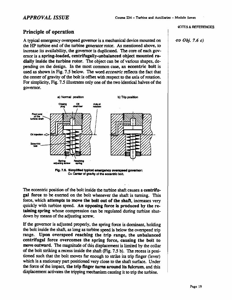
A typical emergency overspeed governor is a mechanical device mounted onthe lIP turbine end of the turbine generator rotor. As mentioned above, toincrease its availability. the governor is duplicated. The core of each governor is a spring-loaded, centrifugally-unbalanced object mounted radially inside the turbine rotor. The object can be of various shapes, depending on the design. In the most common case, an eccentric bolt isused as sbown in Fig. 7.S below. The word eccentric reflects the fact thatthe center of gravity of the bolt is offset with respect to the axis ofrotation.For simplicity, Fig. 7.S illustrates only one of the two identical halves of thegovernor.
The eccentric position of the bolt inside the turbine shaft causes a centrifugal force to be exerted on the bolt whenever the shaft is turning. Thisforce, which attempts to move tbe bolt out of tbe sbaft, increases veryquickly with turbine speed. An opposing force is produced by tbe retaining spring whose compression cso be regulated during turbine shutdown by mesos of the adjusting screw.
If the governor is adjusted properly, the spring force is dominsot, boldingthe bolt inside the shaft, as long as turbine speed is below the overspeed lriprange. Upon overspeed reaching the trip range, the unbalancedcentrifugal force overcomes the spring force, causing the bolt tomove outward. The magnitude of this displacement is limited by the collarof the bolt slriking a recess inside the shaft (Fig. 7.S b). The recess is positioned such that the bolt moves far enough to slrike its trip finger (lever)whicb is a stationary part positioned very close to the shaft surface. Underthe force of the impac~ tbe trip finger turns around its fulcrum, sod thisdisplacement activates the tripping mechsoism causing it to lrip the turbine.
When turbine speed eventually subsides to about 100%, the centrifugalforce acting on the eccentric bolt decreases below the spring force, and thebolt retracts into the shaiL Though this happens. the rest of the trippingmechanism must be reset before nonna! hydraulic floid pressure can be restored in the turbine governing system. and hence, the trip reset.
Testing
To confinn its availability, the emergency overspeed governor is periodically tested in two different ways. One of them - actual overspeed testing- has been mentioned earlier. Because it requires turbine generator unloading and disconnecting from the grid, and because it subjects the machine toincreased stress level, it is performed relatively rarely.
Much more frequently, on-power testing is done. During this test, turbine generator load. remains unchanged, and overspeed is simulated byinjection of turbine lubricating oil into the oil chamber of the governor (Fig. 7.5). The pressure of oil in the chamber exerts an extra force onthe bolt. In most stations, the pressure of oil injection - and hence. the additional force on the eccentric bolt - can be regulated. Thus, not only can asimple freedom of movement test be performed, but also the overspeed tripsetpoint can be checked.
Naturally, on-power testing of the governor should not cause a turbine trip.This is achieved by proper design of the tripping mechanism such that thetripping action of the eccentric bolt under test is isolated and does not causethe tripping mechanism to dump the hydraulic fluid to drains. This isolationdoes not disable the other eccentric bolt which can still trip the turbine,should real emergency overspeed occur during the test.
Failure of eitber cb!lnnel of the emergency overspeed governor topass an actual overspeed test is clear evidence that this channel is unavailable for turbine protection. Because the emergency overspeed governoris so essential to turbine generator safety, such failure results in a mandatory turbine shutdown to repair the governor.
As for on-power tests, note that governor failure may be caused by malfunction of the test circuitry. Therefore, an investigation is necessary. Itsresults affect the required action. Details, available in the appropriate operating manual and/or test procedure, will be covered in the station specifictraining.
SUMMARY OF THE KEY CONCEPTS• Turbine speed reaches the overspeed trip level during actual overspeed
testing of the emergency overspeed governor. Such a high overspeedmay also happen during a load rejection or a nonsequential turbine trip ifthe turbine governing system or some steam valves are malfunctioning.
NOTES & REFERENCES• The emergency overspeed governor enhances turbine protection against
an overspeed accident because the governor can compensate for certainfailures of the turbine governing system or stearn valves. First, the gOY·
emor is independent from these components which nonnally respond toa load rejection or a speed increase. Second, compared with a load rejection, additional turbine steam valves are used to stop the steam flow.Finally, the governor is duplicated to increase its reliability, and undergoes frequent tests to conIum its availability.
• A ry'pical emergency overspeed governor reacts to excessive overspeedby activating the tripping mechanism. This is done by an eccentric bolt(or a similar component) being flung out of the turbine shaft by an unbalanced centrifugal force overcoming the force produced by the retaining spring. The centrifugal force is generated because the centre ofgravity nf the bolt is eccentric with respect to the axis ofrotation.
• Two types of tests of the emergency overspeed governor are performed:aetual overspeed tests and on-power tests.
• During on-power tests, emergency overspeed is simulated by oil injection into the oil chamber inside the governor. This produces an extraforce attempting to throw the bolt out of the shaft.
• If the emergency overspeed governor fails to pass an aetual overspeedtest, the turbine must be shut down and the governor repaired beforeturbine operation can be resumed.
You can now do assignment questions 9-12. ~ Pages 30-31
Page 21
Course 234 - Turbine and Auxiliaries - Module Seven
Page 22
APPROVAL ISSUE
APPROVAL ISSUE
ASSIGI\IMEI\IT
Course 234 - Turbine and Auxiliaries - Module Seven
NOTES & REFERENCES
1. a) During normal operation, the load limiter setpoint is kept (at/somewhat above / somewhat below) full turbine load in order to
b) The load limiter SO!pOjnt is appropriately reduced when _
c) To limit turbine load it (is / is not) enough to limit the no-loadspeed setpoint to the turbine governing systembecause
2. a) Typically, turbine unloading can be initiated by either:
i)
il)
b) The reason why the maximum tmbine unloading is not continued
to zero load is ------
c) If unloading were not accompanied with the appropriate runback,
11. a) The centrifugal force exerted on the eccentric bolt of an emergency ov=!"'ed governor (increases quickly with turbine speed I remains approximately constant).
b) The centrifugal force attempts to _
c) The spring force atttJnplS to _
d) At the trip speed, the centrifugal force (is overcome by lover-
comes) the spring force, causing the bolt to move _
e) The trip mecbanism is activated by the _
moveddueto _
12. a) Two types of testing of the emergency overspeed governor are:
i)
il)
b) While testing the governor at normal turbine speed, ernergency
overspeed is simulated by _
c) The required action in the event of failure of the emergency over-
speed governor to pass an aetual overspeed test is _
Before you move on to the next module, review the objectives and makesure that you can meet their requirements.