Page 1
European Aviation Safety Agency — Rulemaking Directorate
Notice of Proposed Amendment 2013-06
Applicability Process map
Affected
regulations and decisions:
CS-ACNS
AMC-20 Concept Paper:
Terms of Reference:
Rulemaking group:
RIA type:
Technical consultation during NPA drafting:
Duration of NPA consultation:
Review group:
Focussed consultation:
Publication date of the Opinion:
Publication date of the Decision:
No
9 Feb 2009
13 Dec 2010
No
Light
No
3 months
No
No
N/A
2013/Q4
Affected stakeholders:
Design Organisations
Driver/origin: Level Playing Field and Safety
Reference: Commission Regulation (EC) No 29/2009
Commission Implementing Regulation (EU) No 1079/2012
TE.RPRO.00034-003 © European Aviation Safety Agency. All rights reserved.
Proprietary document. Copies are not controlled. Confirm revision status through the EASA Internet/Intranet. Page 1 of 87
Approval requirements for Air-Ground Data Link and
ADS-B in support of Interoperability requirements
and
Miscellaneous improvement to AMC 20
RMT.0099 (20.006(b)) and RMT.0099 (20.016) — 15/04/2013
EXECUTIVE SUMMARY
This NPA contains a draft Decision for new Certification Specifications for Airborne
Communication Navigation and Surveillance (CS-ACNS) that comprises of information related
to the airworthiness and interoperability standards in support of airspace applications. In
particular, the intent of this NPA is to propose new sections for the Certification Specifications
presented in NPA 2012-19. These sections are to provide clear standards and Guidance
Material to ensure safe operations while demonstrating compliance with both Commission
Regulation (EC) No 29/2009 ‘Data link services’ and Commission Implementing Regulation
(EU) No 1079/2012 ‘Voice channels spacing’. In addition, this NPA transposes and updates the
following JAA TGL’s into the EASA regulatory structure:
a. JAA TGL 6 – Reduced Vertical Separation Minima RVSM;
b. JAA TGL 12 – Terrain Awareness Warning System (TAWS).
Page 2
European Aviation Safety Agency NPA 2013-06
TE.RPRO.00034-003 © European Aviation Safety Agency. All rights reserved.
Proprietary document. Copies are not controlled. Confirm revision status through the EASA Internet/Intranet. Page 2 of 87
TABLE OF CONTENTS
A. EXPLANATORY NOTE ........................................................................................... 3
I. GENERAL ......................................................................................................... 3
II. CONSULTATION ................................................................................................. 4
III. COMMENT RESPONSE DOCUMENT ............................................................................. 4
IV. CONTENT OF THE DRAFT OPINION/DECISION ............................................................... 5
V. REGULATORY IMPACT ASSESSMENT .......................................................................... 9
B. DRAFT DECISION .............................................................................................. 12
I. DRAFT DECISION ON CERTIFICATION SPECIFICATIONS, ACCEPTABLE MEANS OF COMPLIANCE, AND
GUIDANCE MATERIAL FOR COMMUNICATION NAVIGATION AND SURVEILLANCE — CS–ACNS BOOK 1 AND
BOOK 2 ................................................................................................................ 12
II DRAFT DECISION AMENDING DECISION NO 2003/12/RM OF THE EXECUTIVE DIRECTOR OF THE
EUROPEAN AVIATION SAFETY AGENCY OF 5 NOVEMBER 2003 ON ACCEPTABLE MEANS OF COMPLIANCE
FOR AIRWORTHINESS OF PRODUCTS, PARTS AND APPLIANCES (‘AMC-20’) .................................. 71
C. CROSS REFERENCE WITH INTEROPERABILITY REGULATIONS .......................... 72
I COMPLIANCE MATRIX WITH COMMISSION REGULATION (EC) NO 29/2009 (DLS IR) ............ 72
II COMPLIANCE MATRIX WITH COMMISSION IMPLEMENTING REGULATION (EU) NO 1079/2012
(VCS IR) ............................................................................................................. 83
Page 3
European Aviation Safety Agency NPA 2013-06
TE.RPRO.00034-003 © European Aviation Safety Agency. All rights reserved.
Proprietary document. Copies are not controlled. Confirm revision status through the EASA Internet/Intranet. Page 3 of 87
A. Explanatory Note
I. General
1. The purpose of this Notice of Proposed Amendment (NPA) is to envisage amending
the Certification Specification (CS-ACNS) as presented in NPA 2012-19 and
AMC-20, with the airworthiness and interoperability standards with respect to Data
link operations, Reduced Vertical Separation Minima (RVSM), 8.33 kHz voice
channel spacing, and Terrain Awareness Warning System (TAWS). Demonstration
of CS-ACNS compliance with Commission Regulation (EC) 29/20091 ‘Data link
services’ and Commission Implementing Regulation (EU) No 1079/20122 ‘Voice
channels spacing’ is provided in Part C of this document. The scope of this
rulemaking activity is outlined in Terms of Reference (ToR) RMT.0599 (20.016) and
RMT.0099 (20.006(b)) and is described in more detail below.
2. The European Aviation Safety Agency (hereafter referred to as the ‘Agency’) is
directly involved in the rule-shaping process. It assists the Commission in its
executive tasks by preparing draft regulations, and amendments thereof, for the
implementation of the Basic Regulation3 which are adopted as ‘Opinions’
(Article 19(1)). It also adopts Certification Specifications, Acceptable Means of
Compliance and Guidance Material to be used in the certification process (Article
19(2)).
3. When developing rules, the Agency is bound to follow a structured process as
required by Article 52(1) of the Basic Regulation. Such process has been adopted
by the Agency’s Management Board and is referred to as ‘The Rulemaking
Procedure’4.
4. This rulemaking activity is included in the Agency’s Rulemaking Programme for
2013-2016. It implements the rulemaking task RMT.0099 (20.006(b))
‘Miscellaneous improvement to AMC-20’ and RMT.0559 (20.016) ‘Approval
requirements for Air-Ground Data Link and ADS-B in support of Interoperability
requirements’ .
5. The text of this NPA has been developed by the Agency. It is submitted for
consultation of all interested parties in accordance with Article 52 of the Basic
Regulation and Articles 5(3) and 6 of the Rulemaking Procedure.
6. The proposed rule has taken into account the development of European Union and
International law (ICAO), and the harmonisation with the rules of other authorities
of the European Union main partners as set out in the objectives of article 2 of the
Basic Regulation. The proposed rule:
1 Commission Regulation (EC) No 29/2009 of 16 January 2009 laying down requirements on data link
services for the single European sky (OJ L13, 17.1.2009, p.3) 2 Commission Implementing Regulation (EU) No 1079/2012 of 16 November 2012 laying down
requirements for voice channels spacing for the single European sky (OJ L 320, 17.11.2012, p.14) 3 Regulation (EC) No 216/2008 of the European Parliament and of the Council of 20 February 2008 on
common rules in the field of civil aviation and establishing a European Aviation Safety Agency, and
repealing Council Directive 91/670/EEC, Regulation (EC) No 1592/2002 and Directive 2004/36/EC. (OJ L 79, 19.03.2008, p. 1). Regulation as last amended by Commission Regulation (EU) No 6/2013 of 8 January 2013 (OJ L 4, 9.1.2013, p. 34).
4 EASA MB Decision 01-2012 of 13 March 2012 amending and replacing MB Decision 08-2007 concerning the procedure to be applied by the Agency for the issuing of opinions, certification specifications and guidance material (‘Rulemaking Procedure’).
Page 4
European Aviation Safety Agency NPA 2013-06
TE.RPRO.00034-002© European Aviation Safety Agency. All rights reserved.
Proprietary document. Copies are not controlled. Confirm revision status through the EASA-Internet/Intranet.
Page 4 of 87
a. takes into account developments of relevant European Union law in particular
those developed within the framework of Single European Sky Interoperability
regulation5; and
b. is equivalent to the ICAO provisions.
II. Consultation
7. To achieve optimal consultation, the Agency is publishing the draft decision of the
Executive Director on its internet site. Comments should be provided within 3
Months in accordance with Article 6(5) of the Rulemaking Procedure. Comments on
this proposal should be submitted by one of the following methods:
8. Please submit your comments using the automated Comment-Response Tool (CRT)
available at http://hub.easa.europa.eu/crt/.
9. The deadline for the submission of comments is 15 July 2013.
III. Comment response document
10. All comments received in time will be responded to and incorporated in a comment
response document (CRD). The CRD will be available on the Agency’s website and
in the Comment-Response Tool (CRT).
5 Regulation (EC) No 552/2004 of the European Parliament and of the Council of 10 March 2004 on the
interoperability of the European Air Traffic Management network (the interoperability Regulation) (OJ
L 96, 31.3.2004, p. 26) as last amended by Regulation (EC) No 1070/2009 of the European Parliament and of the Council of 21 October 2009 (OJ L300, 14.11.2009, p 34)
Page 5
European Aviation Safety Agency NPA 2013-06
TE.RPRO.00034-002© European Aviation Safety Agency. All rights reserved.
Proprietary document. Copies are not controlled. Confirm revision status through the EASA-Internet/Intranet.
Page 5 of 87
IV. Content of the draft Opinion/Decision
11. Summary:
The purpose of this Notice of Proposed Amendment (NPA) is to complement the
Certification Specification (CS-ACNS) as presented in NPA 2012-19 with other
Communications, Navigation and Surveillance related certification and
interoperability standards. CS-ACNS was initially presented for consultation in NPA
2012-19 and contained certification standards for: Mode A/C-only surveillance,
Mode S elementary Surveillance, Mode S Enhanced Surveillance and ADS-B 1090
MHz Extended Squitter. This NPA extends the scope by proposing certification and
interoperability standards for RVSM, 8.33 kHz and TAWS Class A and Class B.
12. These certification standards are primarily based where applicable on:
JAA TGL 6 – RVSM
JAA TGL 7 - 8.33 kHz
JAA TGL 12 - Terrain Awareness Warning System (TAWS)
EASA Special Condition on ATN B1 Data Link installation
13. The certification standard also addresses both Commission Regulation
(EC) No 29/2009, laying down requirements on data link services for the Single
European Sky (SES), and Commission Implementing Regulation (EU) No
1079/2012, laying down requirements for voice channels spacing for the Single
European Sky.
14. It also expands on the certification standard to address Class B equipment in line
with requirements laid down in the Commission Regulation (EU) No 965/20126.
Compliance with SES interoperability requirements
15. The Interoperability Implementing Regulations for Voice Channel Spacing (8.33
kHz) and Data Link were developed in the framework of the SES interoperability
Regulation (EC) No 552/2004 under which the conformity assessment of the
European Air Traffic Management network (EATMN) systems and constituents is
required. An EATMN system is derived from one of the 8 types of systems as
defined in Annex I of Regulation (EC) No 552/2004. In this context, manufacturers
are required to provide an EC Declaration of Conformity (DoC) or Declaration of
Suitability (DSU) for use for the constituents that they place on the market. Air
Navigation Service providers will need to submit an EC Declaration of Verification
(DoV) of systems to their NSA for the EATMN systems that they put into service.
16. Furthermore, with regard to the airborne constituents, the aircraft equipment
design and installation has to be approved by the Agency in accordance with
Regulation (EC) No 748/2012.
17. To avoid any unnecessary burden for aircraft and avionics manufacturers Article
6(a) of the interoperability Regulation as amended by Regulation
(EC) No 1070/2009 introduces an alternative verification of compliance on the basis
of certificates issued by the Agency providing that they include a demonstration of
compliance with the essential requirements of the interoperability Regulation and
the relevant implementing rules for interoperability.
6 Commission Regulation (EU) No 965/2012 of 5 October 2012 laying down technical requirements and
administrative procedures related to air operations pursuant to Regulation (EC) No 216/2008 of the European Parliament and of the Council (OJ L 296, 25.10.2012, p1)
Page 6
European Aviation Safety Agency NPA 2013-06
TE.RPRO.00034-002© European Aviation Safety Agency. All rights reserved.
Proprietary document. Copies are not controlled. Confirm revision status through the EASA-Internet/Intranet.
Page 6 of 87
18. As a result, the Agency certificate issued in accordance with Regulation
(EC) No 216/2008 (as amended by Regulation (EC) 1108/2009) on the basis of
Certification Specification proposed by this NPA are to be considered as an EC
declaration of conformity or suitability for use.
Voice Channel Spacing (8.33 kHz)
19. Subpart B Section 1 (CS ACNS.VCS) ensures airborne communication equipment
compliance for communication equipment based on 8,33 kHz channel spacing with
Commission Implementing Regulation (EU) No 1079/2012, laying down
requirements for the performance and the interoperability of air-ground voice
channels spacing for the SES. This regulation prescribes a phased approach to
ensure that all aircraft are equipped with radio equipment with 8,33 kHz channel
spacing capability before 31 December 2017.
20. The purpose of this NPA is to propose a new section in the CS-ACNS which will
include the voice communication system, safety and interoperability requirements
that allow airborne constituents to comply with the requirements laid down in
Commission Implementing Regulation (EC) No 1079/2012.
21. Additionally TGL 7 certification requirements have been reviewed, amended as
necessary and transposed into CS-ACNS.VCS.
Data link
22. Subpart B Section 2 (CS ACNS.DLS B1) ensures airborne communication equipment
compliance for communication systems based on ATN B1 with Commission
Regulation (EC) No 29/2009 of 16 January 2009 which lays down the requirements
on data link services for the SES. This regulation prescribes a phased approach to
ensure that all IFR aircraft operating above FL285 are equipped with data link
capability.
23. The purpose of this NPA is to propose a new section in the CS-ACNS which will
include the data link aircraft equipment safety and interoperability requirements
that allow airborne constituents to comply with the requirements laid down in
Regulation (EC) No 29/2009.
24. A number of aircraft operate in airspace that required the installation and
operations of FANS 1/A and ATN B1 systems. The proposed CS includes the
standards for dual installations.
25. The initial deployment of the data link services has shown a number of limitations
on the design and implementation of data link aircraft equipment. In particular, it is
found that applicants intending to install a Data Link for CPDLC communications,
may propose one of the following cases:
Single stack with ATN B1. Aircraft intended to operate within EU Airspace.
Single stack without ATN B1, but with other Data Link technology. Aircraft
intended to operate outside EU airspace, but manufactured or modified by EU
Applicants.
Dual stack including ATN B1. Aircraft intended to operate within EU airspace,
and outside EU airspace where other CPDLC Data Link technology are
required.
Additionally, it is found that Regulation (EC) No 29/2009, allows other than
VDL Mode 2 technology, which was not taken into account in the Special
Condition.
Page 7
European Aviation Safety Agency NPA 2013-06
TE.RPRO.00034-002© European Aviation Safety Agency. All rights reserved.
Proprietary document. Copies are not controlled. Confirm revision status through the EASA-Internet/Intranet.
Page 7 of 87
26. The CS proposed by this NPA clarifies the applicability of requirements depending
on the intended use of the CPDLC Data Link, and introduces requirements and
guidance for the Dual Stack installations.
27. Additionally, the CS proposed by this NPA intends to clarify the interoperability
requirements, especially those to be taken from ICAO Doc 9705, instead from ED-
110B.
Terrain Awareness Warning System (TAWS)
28. The standards as defined in JAA TGL 12 have been transposed, updated and
captured the Certification Specification proposed by this NPA within the CS
ACNS.TAWS section.
29. Furthermore, as Commission Regulation (EU) No 965/2012 requires that:
Turbine-powered aeroplanes having an MCTOM of more than 5 700 kg or an
MPSC of more than nine shall be equipped with a TAWS that meets the
requirements for Class A equipment as specified in an applicable standard.
Reciprocating-engine-powered aeroplanes with an MCTOM of more than 5 700
kg or an MOPSC of more than nine shall be equipped with a TAWS that meets
the requirement for Class B equipment as specified in an applicable standard.
the proposed Certification Specification has been extended its scope to cover Class
B equipment installations.
30. ETSO-C151b and ETSO-C92c (for the GPWS functions) requirements have been
taken into account for equipment approval.
31. Finally, the safety recommendations from the ‘report on the accident to AIRBUS
A-320-231, G-MEDA on approach to ADDIS ABEBA Airport Ethiopia –
31 March 2003’ have been taken into account:
Safety recommendation 4: It is recommended that the EASA and FAA review and
revise existing TAWS certification requirements with a view to ensuring that they
protect against common mode failures that could induce a CFIT accident.
Furthermore, the minimum requirements for navigational accuracy of sources used
for TAWS should be tightened to reflect the need of the system to perform its
function. These revised standards should then be applied retrospectively to all
aircraft required to be fitted with TAWS.
Both the FMS and TAWS had sufficient information to identify that there was a
problem with the ADS VOR and the derived information but there is no mechanism
or requirement to communicate this effectively to the crew.
Safety Recommendation 4 is addressed by CS ACNS.TAWS.3030 Positioning
information bullets (a), (b) and (c).
Safety Recommendation 5: It is recommended that the EASA and FAA study the
issues relating to the use of TAWS so that where aircraft source problems are
identified by the system the flight crew can be alerted.
Safety Recommendation 5 is address by CS ACNS.TAWS.3030 Positioning
information bullet (e).
Safety Recommendation 6: It is recommended that the EASA and FAA consider
whether the crew should be alerted when a FMS has identified a recurrent problem
Page 8
European Aviation Safety Agency NPA 2013-06
TE.RPRO.00034-002© European Aviation Safety Agency. All rights reserved.
Proprietary document. Copies are not controlled. Confirm revision status through the EASA-Internet/Intranet.
Page 8 of 87
with a particular navigation aid and, furthermore, consider whether the subsequent
use of that navigation aid for position information is desirable.
Safety Recommendation 6 is addressed by CS ACNS.TAWS.3030 Positioning
information bullet (c).
Reduced Vertical Separation Minima (RVSM)
32. JAA TGL 6 RVSM aircraft certification standard has been transposed updated and
captured the Certification Specification proposed by this NPA within section
CS ACNS.RVSM section.
33. Thus the scope of this NPA is to amend the Certification Specifications (CS-ACNS)
as proposed in NPA 2012-19 with additional provisions in
Subpart B, Communication, for 8.33kHz VCS and Data Link Services, and
Subpart E, Others, for TAWS and RVSM.
Page 9
European Aviation Safety Agency NPA 2013-06
TE.RPRO.00034-002© European Aviation Safety Agency. All rights reserved.
Proprietary document. Copies are not controlled. Confirm revision status through the EASA-Internet/Intranet.
Page 9 of 87
V. Regulatory Impact Assessment
(a) Process and consultation
In accordance with the Rulemaking Procedure, the Agency needs to conduct a Regulatory
Impact Assessment (RIA) of each proposed rule by analysing some potential and suitable
options for rulemaking, and comparing them in terms of their safety, environment,
economic, social, and regulatory harmonisation impacts.
Therefore, the aim of the RIA is to support the Agency and the decision makers to
identify the best option to achieve the objective of this rulemaking activity as defined by
the Terms of Reference for RMT.0559 (20.016) dated 10 December 2010 and
RMT.0099(20.006) dated 9 February 2009.
This RIA was developed by the Agency during the preparation of the draft Decision and
the resulting draft Decision takes into account the lessons learned from the current data
link (Link-2000) deployment programme and with the current operations of 8.33KHz
VCS, TAWS and RVSM.
(b) Issue analysis and risk assessment
(1) What is the issue and the current regulatory framework?
The issue of this RIA is based on the need to establish requirements that permits
the airborne community to comply with airspace operational requirements. In
particular, the issue is to permit simultaneously compliance with the two separate
regulatory processes associated with Commission Regulation (EU) 748/20127 and
Regulation (EC) 552/2004, thus alleviating the requirement for multiple approvals,
certificates, and EC declarations for constituents and installations.
The issue is to address the certification standard for on-board installations and
ensuring compliance with Commission Regulation (EC) No 29/2009 and Commission
Implementing Regulation (EU) 1079/2012 for aircraft that are subject to that
regulation. In addition, it addresses certification standard for those aircraft that are
required to be required with TAWS or will operated in RVSM airspace.
(2) Who is affected?
Aircraft and avionics manufacturers, design organisations and aircraft operators
developing or installing 8.33KHZ Voice communications, Data Link communications,
TAWS and RVSM systems.
(3) What are the risks (probability and severity)?
If the current situation remains as it is, it will be difficult to apply the provisions of
Article 6a of the interoperability Regulation without a standard that had been
demonstrated to comply with the requirement of interoperability implementing rule.
This has the possibility to further delay compliance with Commission Regulation
(EC) No 29/2009 and the implementation of Commission Implementing Regulation
(EU) No 1079/2012. Furthermore, the non-availability of the CS that include all
airworthiness and interoperability requirements may result in aircraft not be fully
interoperable with the subsequent safety risks that are attributed to the incorrect
communication.
(c) Objectives
7 Commission Regulation (EU) No 748/2012 of 3 August 2012 laying down implementing rules for the
airworthiness and environmental certification of aircraft and related products, parts and appliances, as well as for the certification of design and production organisations
Page 10
European Aviation Safety Agency NPA 2013-06
TE.RPRO.00034-002© European Aviation Safety Agency. All rights reserved.
Proprietary document. Copies are not controlled. Confirm revision status through the EASA-Internet/Intranet.
Page 10 of 87
The overall objectives of the Agency are defined in Article 2 of Regulation
(EC) No 216/2008 (the Basic Regulation): maintain a high and uniform aviation safety
level with cost-efficient rules.
The specific objectives are:
To establish standards that permit the airborne community to comply with airspace
operational requirements related to the installation of data link and 8.33KHz voice
communication installations that can be used to ensure compliance with the
European regulations as specified in Commission Regulation (EC) No 29/2009 and
the implementation Commission Implementing Regulation (EU) No 1079/2012.
To transpose standards within the EASA regulatory framework for TAWS and RVSM
installation previously defined within JAA material (TGL 6 and TGL12).
To alleviate the requirement for multiple approvals, certificates and EC declarations
for parts and appliances and installation.
(d) Options identified
Option 0: Do nothing.
Option 1: The provision of an appropriate Certification Specification. for data link and
8.33KHz voice communication installations that can be used to ensure compliance with
the European airspace regulation as specified in Commission Regulation (EC) No 29/2009
and the implementation Commission Implementing Regulation (EU) No 1079/2012. It will
also provide the appropriate certification standard, within the EASA regulatory framework
for TAWS and RVSM installation previous defined within JAA material.
(e) Analysis of the impacts
(1) Safety impacts
Option 0, based on existing airworthiness certification material, will not ensure that
the requirements as specified in Commission Regulation (EC) No 29/2009 and
Commission Implementing Regulation (EU) No 1079/2012 are met. In particular, no
suitable certification material currently exists for data link communication in
support of the European applications.
Option 1. will improve safety and interoperability while ensuring that the
requirements as specified in Commission Regulation (EC) No 29/2009 and the
implementation Commission Implementing Regulation (EU) No 1079/2012.
Furthermore, Option 1 ensures a harmonised airworthiness certification process.
(2) Environmental impacts
There is no environmental impact difference between options 0, and 1.
(3) Social impacts
There is no social impact difference between options 0, and 1.
(4) Economic impacts
The economic impact associated with the requirement to install data link
communications, and 8.33KHz voice communication TAWS and RVSM systems is
outside the scope of this NPA. However, with respect to demonstrating compliance,
Option 0: This will require multiple certificates to be issued with the potential to
increase the administrative burden and associated costs;
Option 1: This will provide transparency with respect to the required certification
standard, so the avionics manufacturers and integrators will not lose time during
the certification process, thus reducing the cost with respect to options 0.
Page 11
European Aviation Safety Agency NPA 2013-06
TE.RPRO.00034-002© European Aviation Safety Agency. All rights reserved.
Proprietary document. Copies are not controlled. Confirm revision status through the EASA-Internet/Intranet.
Page 11 of 87
(5) Proportionality issues
The two options provide the same assurance of equity and fairness among all
concerned sectors.
(6) Impact on regulatory coordination and harmonisation
Option 0 does not allow compliance with Commission Regulation (EC) No 29/2009
or Commission Implementing Regulation (EU) No 1079/2012 to be demonstrated as
a result of a certificate issued by EASA. Furthermore, the continued application of
the forma JAA TGL material is not transparent to all stakeholders.
Option 1 provides a simplified and unique approach that satisfies the requirements
posed by all regulatory frameworks. Furthermore, it integrates lessons learned from
existing TAWS and RVSM applications.
(f) Conclusion and preferred option
(1) Comparison of the positive and negative impacts for each option evaluated.
Option 0 does not allow compliance with Commission Regulation (EC) No 29/2009
and Commission Implementing Regulation (EU) No 1079/2012 to be demonstrated
via the application of a single process. It does not permit transparency of the
application of the JAA TGL material.
Option 1 ensures a simplified and coherent approach to the aircraft communications
required by Commission Regulation (EC) No 29/2009 and Commission
Implementing Regulation (EU) No 1079/2012 and globally through the application
of a single process that has to be applied to the aircraft equipment design and
installation in accordance with EASA regulation (EC) No 748/2012. It also enable a
transparent application of the standards for TAWS and RVSM.
(2) Final assessment and recommendation of a preferred option:
The Agency concludes that Option 1 is the preferred option.
Page 12
European Aviation Safety Agency NPA 2013-06
TE.RPRO.00034-003 © European Aviation Safety Agency. All rights reserved.
Proprietary document. Copies are not controlled. Confirm revision status through the EASA Internet/Intranet. Page 12 of 87
B. Draft Decision
The text of the amendment is arranged to show deleted text, new text or new paragraph
as shown below:
1. deleted text is shown with a strike through: deleted
2. new text or changed is highlighted with grey shading: new
3. … indicates that remaining text is unchanged in front of or following the reflected
amendment.
I. Draft Decision on Certification Specifications, Acceptable Means of Compliance,
and Guidance material for Communication Navigation and Surveillance —
CS–ACNS Book 1 and Book 2
Book 1
SUBPART A — GENERAL
CS ACNS.GEN.1000 Applicability
…
(c) Commission Regulation (EC) No 29/2009 of 16 January 2009 laying down requirements
on data link services for the Single European Sky; and
(d) Commission Implementing Regulation (EU) No 1079/2012 of 16 November 2012 laying
down requirements for voice channels spacing for the Single European Sky.
CS ACNS.GEN.1010 Definitions
…
‘Altimetry System Error (ASE)’ refers to the difference between the altitude indicated by
the altimeter display, assuming a correct altimeter barometric setting, and the pressure
altitude corresponding to the undisturbed ambient pressure.
‘Automatic Altitude Control System’ means any system that is designed to automatically
control the aircraft to a referenced pressure altitude.
‘Advisory Alerts’ means the level or category of alert for conditions that require flight crew
awareness and may require subsequent flight crew response.
‘Alert’ means a generic term used to describe a flight deck indication meant to attract the
attention of and identify to the flight crew a non-normal operational or aeroplane system
condition. Alerts are classified at levels or categories corresponding to Warning, Caution, and
Advisory. Alert indications also include non-normal range markings (for example, exceedances
on instruments and gauges).
‘Aural Alert’ means a discrete sound, tone, or verbal statement used to annunciate a
condition, situation, or event.
Page 13
European Aviation Safety Agency NPA 2013-06
TE.RPRO.00034-002© European Aviation Safety Agency. All rights reserved.
Proprietary document. Copies are not controlled. Confirm revision status through the EASA-Internet/Intranet.
Page 13 of 87
‘ATS communications management service’ means a service that provides automated
assistance to flight crews and air traffic controllers for conducting the transfer of ATC
communications (voice and data).
‘ATS Clearance and Information service’ means a service that provides flight crews and
controllers with the ability to conduct operational exchanges.
‘ATS microphone check service’ means a service that provides air traffic controllers with
the capability to send an instruction to several data link equipped aircraft, at the same time, in
order to instruct flight crews to verify that their voice communication equipment is not blocking
a given voice channel.
‘Caution’ means the level or category of alert for conditions that require immediate flight crew
awareness and a less urgent subsequent flight crew response than a warning alert.
‘Controlled Flight Into Terrain (CFIT)’ means an accident or incident in which an aircraft,
under the full control of the pilot, is flown into terrain, obstacles, or water.
‘CPDLC’ is the ICAO standardised procedure for controller-pilot communications. CPDLC takes
the form of an application, present on both aircraft and ground-based ATC centres that
provides support for the Data Link Communications Initiation Capability (DLIC), ATS
communications management service (ACM), ATS Clearance and Information service (ACL)
and ATS microphone check service (AMC).
‘Data Link’ is a communication technology where ‘Data Link’ equipped aircraft communicate
with ‘Data Link’ capable ground units to exchange digital information (bi-directional exchange).
‘Data Link Communications Initiation Capability’ means a service that enables the
exchange of the necessary information for the establishment of data link communications
between the ground and aircraft data link systems.
‘Downlink’ is a transfer of information, generated by an aircraft (not necessarily airborne)
and sent to the ground for further processing by an ATC Centre.
‘Failure’ An occurrence that affects the operation of a component, part, or element such that
it can no longer function as intended. This includes both loss of function and malfunction.
‘False Alert’ means an incorrect or spurious alert caused by a failure of the alerting system
including the sensor.
‘Forward Looking Terrain Avoidance (FLTA)’ Looks ahead of the aeroplane along and
below the aeroplane’s lateral and vertical flight path and provides suitable alerts if a potential
CFIT exists.
‘Group Aircraft’ is a group of aircraft with similar altitude keeping equipment configurations
and performance characteristics that are combined together for the purposes of statistical
generic performance evaluation. Typically group aircraft refers to aircraft constructed to the
same Type Certificate, Service Bulletin or Supplementary Type Certificate.
‘Hazard’ means a state or set of conditions that together with other conditions in the
environment can lead to an accident.
‘Non-group aircraft’ refers to an aircraft that is not a group aircraft but which is submitted
for airworthiness approval on the characteristics of the unique airframe
‘Nuisance Alert’ means an alert generated by a system that is functioning as designed but
which is inappropriate or unnecessary for the particular condition.
‘RVSM Flight Envelope’ may be considered to be in two parts; the basic RVSM flight
envelope and the full RVSM flight envelope. The basic envelope includes those ranges of Mach
numbers and gross weights at which the aircraft can most frequently be expected to operate at
RVSM levels (i.e. FL 290 to FL 410 (or maximum attainable altitude)). The full envelope refers
Page 14
European Aviation Safety Agency NPA 2013-06
TE.RPRO.00034-002© European Aviation Safety Agency. All rights reserved.
Proprietary document. Copies are not controlled. Confirm revision status through the EASA-Internet/Intranet.
Page 14 of 87
to the entire range of Mach numbers, gross weights and altitude values that the aircraft can be
operated in RVSM airspace.
‘RVSM operational flight envelope’ is the Mach number, W/, and altitude ranges over
which an aircraft can be operated in cruising flight within the RVSM airspace.
‘Required Obstacle Clearance (ROC)’ means required vertical clearance expressed in ft
between an aircraft and an obstruction.
‘Required Terrain Clearance (RTC)’ A TAWS FLTA mode that alerts when the aeroplane is
above the terrain in the aeroplane’s projected flight path, but the projected amount of terrain
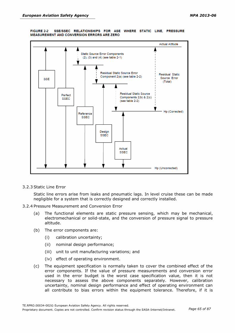
clearance is considered unsafe for the particular phase of flight.‘Static Source Error (SSE)’ is
the difference between the pressure sensed by the static system at the static port and the
undisturbed ambient pressure.
‘Static Source Error Correction (SSEC)’ is the correction for the residual static error to
ensure compliance with performance requirements.
‘Search Volume’ means a volume of airspace around the aeroplane’s current and projected
path that is used to define a TAWS alert condition.
‘Terrain Cell’ means a grid of terrain provided by the TAWS database which identifies the
highest terrain elevation within a defined geographical area. Terrain cell dimensions and
resolution can vary depending on the needs of the TAWS system and availability of data. If a
supplier desires, obstacle height can be included in the terrain elevation.
‘Uplink’ is a transfer of information, issued from any ground-based entity (typically: the ATC
Centre under which the aircraft is under responsibility) to an aircraft (not necessarily
airborne).
‘Worst case avionics’ means a combination of tolerance values, specified by the aircraft
constructor for the altimetry fit into the aircraft which gives the largest combined absolute
value for residual SSE plus avionics errors.
‘Warning’ means the level or category of alert for conditions that require immediate flight
crew awareness and immediate flight crew response.
…
Page 15
European Aviation Safety Agency NPA 2013-06
TE.RPRO.00034-002© European Aviation Safety Agency. All rights reserved.
Proprietary document. Copies are not controlled. Confirm revision status through the EASA-Internet/Intranet.
Page 15 of 87
SUBPART B — COMMUNICATIONS
SECTION 1 – VOICE CHANNEL SPACING (VCS)
General
CS ACNS.VCS.1000 Applicability
The section provides standards for aircraft voice communication systems operating in the band
117,975-137 MHz.
System functional requirements
CS ACNS.VCS.2000 Voice Communication System
(see AMC1 ACNS.VCS.2000)
(a) The voice communication systems are to be capable of 8.33 kHz and 25 kHz channel spacing
(b) Voice communication systems are to be capable of operating with off-set carrier frequencies
on 25 kHz channel spacing.
System performance requirements
CS ACNS.VCS.3000 Performance Requirements
The voice communication systems conforms to the performance requirements of the following
sections of ICAO Annex 10, Volume III, Part 2 (Second Edition — July 2007 incorporating
Amendment No 85) Chapter 2 ‘Aeronautical Mobile Service’:
(a) Section 2.1 ‘Air-ground VHF communication system characteristics’.
(b) Section 2.2 ‘System characteristics of the ground installations’ of ICAO.
(c) Section 2.3.1 ‘Transmitting function’.
(d) Section 2.3.2 ‘Receiving function’ excluding sub-section 2.3.2.8 ‘VDL — Interference
Immunity Performance’.
CS ACNS.VCS.3010 Integrity
The voice communication systems are designed commensurate with a major failure condition.
CS ACNS.AC.3020 Continuity
The probability of the loss of voice communication is better than or equal to remote.
Installation requirements
CS ACNS.VCS.4000 Flight Deck Interface
(see AMC1 ACNS.VCS.4000)
A means is provided to:
(a) select the voice communications channel;
(b) display the selected voice communications channel to the flight crew;
Page 16
European Aviation Safety Agency NPA 2013-06
TE.RPRO.00034-002© European Aviation Safety Agency. All rights reserved.
Proprietary document. Copies are not controlled. Confirm revision status through the EASA-Internet/Intranet.
Page 16 of 87
(c) indicate the non-operational status or failure of the system without undue delay;
SECTION 2 –DATA LINK SERVICES (DLS)
General
CS ACNS.DLS.B1.1000 Applicability
(See GM1 ACNS.DLS.B1.1000)
This section provides the airworthiness standard for ATN B1 with VDL Mode 2 data link aircraft
systems to be installed on aircraft intended to be used for CPDLC Communications.
CS ACNS.DLS.B1.1001 Installation Requirements
(See AMC1 ACNS.DLS.B1.1001)
The data link system includes a means to enable data communication and flight deck
annunciations and controls.
Flight deck control and indication capabilities
CS ACNS.DLS.B1.1010 Flight Deck Interface
(See AMC1 ACNS.DLS.B1.1010)
(a) A means is provided:
(1) to inform clearly and unambiguously when uplinked messages are received;
(2) for the flight crew to activate or deactivate the data link services;
(3) for the flight crew to know in real time the identity of the ATS provider(s)
connecting with the aircraft;
(4) to display all messages, with minimal flight crew action, in a format that is easy to
comprehend and distinguishable from each other;
(5) for the flight crew to respond to ATS messages;
(6) to inform the flight crew that pending or open messages are waiting for a response;
(7) for the flight crew to determine the status of the data link system;
(b) A means is provided to prohibit the deletion, confirmation, or clearance of a message
until the entire message is displayed.
CS ACNS.DLS.B1.1011 Dual Data Link Capabilities (Dual stack)
(See AMC1 ACNS.DLS.B1.1011)
For aircraft integrating both FANS 1/A and ATN B1 CPDLC applications:
(a) Control and display: Messages with the same intent that are transmitted or received
through these technologies are displayed in the same way.
(b) Alerting: Where a common alerting is not demonstrable, a mean is provided to
distinguish between the alerting scheme in a format that is easy to comprehend .
Page 17
European Aviation Safety Agency NPA 2013-06
TE.RPRO.00034-002© European Aviation Safety Agency. All rights reserved.
Proprietary document. Copies are not controlled. Confirm revision status through the EASA-Internet/Intranet.
Page 17 of 87
ATN B1 data link
CS ACNS.DLS.B1.2000 Data Link Services
(See AMC1 ACNS.DLS.B1.2000)
The data link system provides the following services:
(a) Data Link Initiation Capability (DLIC);
(b) ATC Communications Management (ACM);
(c) ATC Clearances and Information (ACL); and
(d) ATC Microphone Check (AMC).
CS ACNS.DLS.B1.2001 Protection mechanism
(See AMC1 ACNS.DLS.B1.2001 AMC2 ACNS.DLS.B1.2001 AMC3 ACNS.DLS.B1.2001, GM1
ACNS.DLS.B1.2001, GM2 ACNS.DLS.B1.2001, and GM3 ACNS.DLS.B1.2001)
A means is provided to protect the integrity of the message.
System performance requirements
CS ACNS.DLS.B1.3000 Integrity
The data link system is designed commensurate with a minor failure condition.
CS ACNS.DLS.B1.3010 Continuity
The data link system is designed to an allowable qualitative probability of probable
Time
CS ACNS.DLS.B1.3101 Universal Time Coordinated (UTC)
(See AMC1 ACNS.DLS.B1.3101)
For time synchronisation a valid UTC time source is to be used.
Data link initiation capability (DLIC) service messages
CS ACNS.DLS.B1.3201 DLIC Uplink Messages
(see AMC1 ACNS.DLS.B1.3201)
The data link system is capable of receiving and processing the following messages for the
DLIC logon and contact functions:
Function Message
Logon CMLogonResponse
Contact CMContactRequest
Page 18
European Aviation Safety Agency NPA 2013-06
TE.RPRO.00034-002© European Aviation Safety Agency. All rights reserved.
Proprietary document. Copies are not controlled. Confirm revision status through the EASA-Internet/Intranet.
Page 18 of 87
CS ACNS.DLS.B1.3202 DLIC Downlink Messages
(see AMC1 ACNS.DLS.B1.3202)
The data link system is capable of sending the following messages for the DLIC logon and
contact functions:
Function Message
Logon CMLogonRequest
Contact CMContactResponse
CS ACNS.DLS.B1.3203 DLIC Initiation when in CPDLC Inhibited State (Uplink)
When the data link system is in the ‘CPDLC inhibited’ state, DLIC Contact Request is processed
but the system is remaining in the ‘CPDLC inhibited’ state.
CPDLC Messages
CS ACNS.DLS.B1.3301 CPDLC Uplink Messages
(See AMC1 ACNS.DLS.B1.3301, AMC2 ACNS.DLS.B1.3301, GM1 ACNS.DLS.B1.3301 and GM2
ACNS.DLS.B1.3301)
The data link system is capable of receiving, processing and displaying the following message
elements:
ID Message
UM0 UNABLE
UM1 STANDBY
UM3 ROGER
UM4 AFFIRM
UM5 NEGATIVE
UM19 MAINTAIN [level]
UM20 CLIMB TO [level]
UM23 DESCEND TO [level]
UM26 CLIMB TO REACH [level] BY [time]
UM27 CLIMB TO REACH [level] BY [position]
UM28 DESCEND TO REACH [level] BY [time]
UM29 DESCEND TO REACH [level] BY [position]
UM46 CROSS [position] AT [level]
UM47 CROSS [position] AT OR ABOVE [level]
UM48 CROSS [position] AT OR BELOW [level]
Page 19
European Aviation Safety Agency NPA 2013-06
TE.RPRO.00034-002© European Aviation Safety Agency. All rights reserved.
Proprietary document. Copies are not controlled. Confirm revision status through the EASA-Internet/Intranet.
Page 19 of 87
ID Message
UM51 CROSS [position] AT [time]
UM52 CROSS [position] AT OR BEFORE [time]
UM53 CROSS [position] AT OR AFTER [time]
UM54 CROSS [position] BETWEEN [time] AND [time]
UM55 CROSS [position] AT [speed]
UM61 CROSS [position] AT AND MAINTAIN
UM64 OFFSET [specifiedDistance] [direction] OF ROUTE
UM72 RESUME OWN NAVIGATION
UM74 PROCEED DIRECT TO [position]
UM79 CLEARED TO [position] VIA [routeClearance]
UM80 CLEARED [routeClearance]
UM82 CLEARED TO DEVIATE UP TO [specifiedDistance] [direction] OF ROUTE
UM92 HOLD AT [position] AS PUBLISHED MAINTAIN [level]
UM94 TURN [direction] HEADING [degrees]
UM96 CONTINUE PRESENT HEADING
UM106 MAINTAIN [speed]
UM107 MAINTAIN PRESENT SPEED
UM108 MAINTAIN [speed] OR GREATER
UM109 MAINTAIN [speed] OR LESS
UM116 RESUME NORMAL SPEED
UM117 CONTACT [unitname] [frequency]
UM120 MONITOR [unitname] [frequency]
UM123 SQUAWK [code]
UM133 REPORT PRESENT LEVEL
UM148 WHEN CAN YOU ACCEPT [level]
UM157 CHECK STUCK MICROPHONE [frequency]
UM159 ERROR [errorInformation]
UM160 NEXT DATA AUTHORITY [facility]
UM162 SERVICE UNAVAILABLE
UM165 THEN
UM171 CLIMB AT [verticalRate] MINIMUM
UM172 CLIMB AT [verticalRate] MAXIMUM
UM173 DESCEND AT [verticalRate] MINIMUM
UM174 DESCEND AT [verticalRate] MAXIMUM
UM179 SQUAWK IDENT
Page 20
European Aviation Safety Agency NPA 2013-06
TE.RPRO.00034-002© European Aviation Safety Agency. All rights reserved.
Proprietary document. Copies are not controlled. Confirm revision status through the EASA-Internet/Intranet.
Page 20 of 87
ID Message
UM183 [freetext]
UM190 FLY HEADING [degrees]
UM196 [freetext]
UM203 [freetext]
UM205 [freetext]
UM211 REQUEST FORWARDED
UM213 [facilitydesignation] ALTIMETER [altimeter]
UM215 TURN [direction] [degrees]
UM222 NO SPEED RESTRICTION
UM227 LOGICAL ACKNOWLEDGEMENT
UM231 STATE PREFERRED LEVEL
UM232 STATE TOP OF DESCENT
UM237 REQUEST AGAIN WITH NEXT UNIT
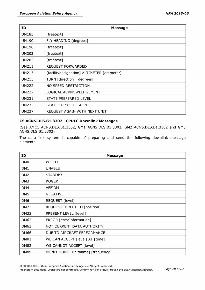
CS ACNS.DLS.B1.3302 CPDLC Downlink Messages
(See AMC1 ACNS.DLS.B1.3302, GM1 ACNS.DLS.B1.3302, GM2 ACNS.DLS.B1.3302 and GM3
ACNS.DLS.B1.3302)
The data link system is capable of preparing and send the following downlink message
elements:
ID Message
DM0 WILCO
DM1 UNABLE
DM2 STANDBY
DM3 ROGER
DM4 AFFIRM
DM5 NEGATIVE
DM6 REQUEST [level]
DM22 REQUEST DIRECT TO [position]
DM32 PRESENT LEVEL [level]
DM62 ERROR [errorInformation]
DM63 NOT CURRENT DATA AUTHORITY
DM66 DUE TO AIRCRAFT PERFORMANCE
DM81 WE CAN ACCEPT [level] AT [time]
DM82 WE CANNOT ACCEPT [level]
DM89 MONITORING [unitname] [frequency]
Page 21
European Aviation Safety Agency NPA 2013-06
TE.RPRO.00034-002© European Aviation Safety Agency. All rights reserved.
Proprietary document. Copies are not controlled. Confirm revision status through the EASA-Internet/Intranet.
Page 21 of 87
ID Message
DM98 [freetext]
DM99 CURRENT DATA AUTHORITY
DM100 LOGICAL ACKNOWLEDGEMENT
DM106 PREFERRED LEVEL [level]
DM107 NOT AUTHORIZED NEXT DATA AUTHORITY
DM109 TOP OF DESCENT [time]
Data link services requirements
CS ACNS.DLS.B1.4101 Data Link Initiation Capability (DLIC) Service
(See AMC 1 ACNS.DLS.B1.4101 and GM1 ACNS.DLS.B1.4101)
The data link system for DLIC should conform with section 4.1, 4.2.2 and 4.3.2 of EUROCAE
Document ED-120, including change 1 and change 2 and section 2.2.1 and 4.1 of EUROCAE
Document ED-110B.
CS ACNS.DLS.B1.4201 ATC Communications Management (ACM) Service
(See AMC1 ACNS.DLS.B1.4201 and GM1 ACNS.DLS.B1.4201)
The data link system for ACM should conform with section 5.1.1, 5.1.2.3 (excluding
requirements relating to downstream clearance) and 5.1.3.2 of EUROCAE Document ED-120,
including change 1 and change 2.
CS ACNS.DLS.B1.4301 ACL Service Safety Requirements
(See AMC1 ACNS.DLS.B1.4301 and GM1 ACNS.DLS.B1.4301)
The data link system for ACL should conform with section 5.2.1, 5.2.2.3 and 5.2.3.2 of
EUROCAE Document ED-120, including change 1 and change 2.
CS ACNS.DLS.B1.4401 ATC Microphone Check (AMC) Service
The data link system for AMC should conform with section 5.3.1, 5.3.2.3 and 5.3.3.2 of
EUROCAE Document ED-120, including change 1 and change 2.
Interoperability Requirements
CS ACNS.DLS.B1.4531 Network Layer Requirements
(See AMC1 ACNS.DLS.B1.4531 and GM1 ACNS.DLS.B1.4531)
The ATN Router conforms to Class 6 with the capability to support Inter-domain routing
protocol (IDRP) .
CS ACNS.DLS.B1.4541 Transport Layer Protocol Requirements
(See AMC1 ACNS.DLS.B1.4541 and GM1 ACNS.DLS.B1.4541)
The ATN Connection Oriented Transport Protocol (COTP), conforms to Transport Protocol Class
4.
CS ACNS.DLS.B1.4551 Session Layer Requirement
(See AMC1 ACNS.DLS.B1.4551)
Page 22
European Aviation Safety Agency NPA 2013-06
TE.RPRO.00034-002© European Aviation Safety Agency. All rights reserved.
Proprietary document. Copies are not controlled. Confirm revision status through the EASA-Internet/Intranet.
Page 22 of 87
ATN Session protocol is capable of supporting the following session protocol data units
(SPDUs):
Abbreviation Full SPDU Name
SCN Short Connect
DRPSAC Short Accept
SACC Short Accept Continue
SRF Short Refuse
SRFC Short Refuse Continue
CS ACNS.DLS.B1.4561 Presentation Layer Requirements
(See AMC ACNS.DLS.B1.4561)
ATN Presentation protocol is capable of supporting the presentation protocol data units
(PPDUs) listed in the following table:
Abbreviation Full PPDU Name
SHORT-CP Short Presentation Connect, unaligned PER
SHORT-CPA Short Presentation Connect Accept, unaligned PER
SHORT-CPR Short Presentation Connect Reject
CS ACNS.DLS.B1.4571 Application Layer Requirements
(See AMC1 ACNS.DLS.B1.4571 and GM1 ACNS.DLS.B1.4571)
The Application Layer is to be application-independent (also known as ‘Layer 7a’), and
composed of a Convergence Function supporting operations of an Application Control Service
Element (ACSE).
Page 23
European Aviation Safety Agency NPA 2013-06
TE.RPRO.00034-002© European Aviation Safety Agency. All rights reserved.
Proprietary document. Copies are not controlled. Confirm revision status through the EASA-Internet/Intranet.
Page 23 of 87
SUBPART E – OTHERS
SECTION 1 – TERRAIN AWARENESS WARNING SYSTEM (TAWS)
General
CS ACNS.TAWS.1000 Applicability
(See GM1 ACNS.TAWS.1000)
This section provides the airworthiness standards applicable to Terrain Awareness Warning
System Class A and Class B for aeroplanes.
CS ACNS.TAWS.1010 TAWS Equipment Approval
(See AMC1 ACNS.TAWS.1010)
The TAWS is Class A or Class B approved equipment.
System functional requirements
CS ACNS.TAWS.2010 Required Functions and Interfaces
(See AMC1 ACNS.TAWS.2010, AMC2 ACNS.TAWS.2010)
TAWS Class A or Class B provides suitable alerting and warning capabilities and other system
interfaces to support the following functions:
TAWS System Function Class A
TAWS
Class B
TAWS
Alerting Imminent contact with ground indications (GPWS
functions) including:
(1) excessive Rates of Descent;
(2) negative Climb Rate or Altitude Loss After
Take-Off or Go-around.
A Voice callout when descending through a
predefined altitude above the runway threshold
elevation for landing.
x
x
With a
500 ft call
out
A forward Looking Terrain Avoidance (FLTA) function,
including:
a Reduced Required Terrain Clearance (RTC)
function;
an Imminent Terrain Impact function;
a FLTA Turning Flight function.
x x
A Premature Descent Alert (PDA) function, including
detection and alerting for Premature Descents Along
the Final Approach Segment
x x
Excessive Closure Rate to Terrain x
Flight Into Terrain When not in Landing Configuration x
Page 24
European Aviation Safety Agency NPA 2013-06
TE.RPRO.00034-002© European Aviation Safety Agency. All rights reserved.
Proprietary document. Copies are not controlled. Confirm revision status through the EASA-Internet/Intranet.
Page 24 of 87
TAWS System Function Class A
TAWS
Class B
TAWS
Excessive Downward Deviation from a glide slope or
glide path x
TAWS and sensor failure monitoring and
annunciation function x x
Capability to initiate the TAWS self-test function on
the ground and where feasible in the air x x
Interfaces A terrain display capability x
Capability to drive a terrain display x
The use of position source input x x
The use of landing guidance deviation input x
The use of radio altimeter sensor input x
The use of Terrain and Airport information x x
Interface with the flight recording system to record
TAWS alerts and inhibition of the FLTA or PDA
functions
x x
The use of landing gear and flaps position x x
The use of roll attitude input x x
The interface with flight deck audio systems x x
CS ACNS.TAWS.2020 FLTA function requirements
(See AMC1 ACNS.TAWS.2020)
Provide an FLTA function that:
(a) looks ahead of the aeroplane, within the search volume, which consists of a computed
look ahead distance, a lateral distance on both sides of the aeroplane’s flight path, and a
specified look down distance based upon the aeroplane’s vertical flight path. The lateral
search volume expands as necessary to accommodate turning flight. The FLTA search
volume is compatible with the accuracy of the TAWS navigation source;
(b) that gives timely alerts in the event terrain is predicted to penetrate the search volume;
(c) is available during all airborne phases of flight including turning flight;
(d) gives Required Terrain Clearance (RTC) alerts when the aeroplane is currently above the
terrain in the aeroplane’s projected flight path but the projected amount of terrain
clearance is considered unsafe for the particular phase of flight.
TABLE 1
TAWS REQUIRED TERRAIN CLEARANCE (RTC) BY
PHASE OF FLIGHT
TAWS (RTC)
Level Flight
TAWS (RTC)
Descending
/climbing
En route 700 ft 500 ft
Terminal (Intermediate Segment) 350 ft 300 ft
Approach 150 ft 100 ft
Departure (above 400 ft) 100 ft 100 ft
Page 25
European Aviation Safety Agency NPA 2013-06
TE.RPRO.00034-002© European Aviation Safety Agency. All rights reserved.
Proprietary document. Copies are not controlled. Confirm revision status through the EASA-Internet/Intranet.
Page 25 of 87
(e) gives Imminent Terrain Impact alerts when the aeroplane is currently below the elevation
of a terrain cell along the aeroplane’s lateral projected flight path and, based upon the
vertical projected flight path, the equipment predicts that the terrain clearance will be
less than the value given in the RTC column of Table 1.
(f) gives alerts for the Imminent Terrain Impact and Required Terrain Clearance functions
when the aeroplane is in turning flight.
CS ACNS.TAWS.2030 PDA function requirements
(See GM1 ACNS.TAWS.2030)
Provide a Premature Descent Alert function:
(a) to determine if the aeroplane is significantly below the normal approach flight path to a
runway and in such a case issue an alert, based on the current position and flight path
information of the aeroplane, as determined from a suitable navigation source and
airport database;
(b) that is available on all types of instrument approaches including straight-in approaches,
circling approaches and approaches that are not aligned within 30 degrees of the runway
heading.
CS ACNS.TAWS.2040 Class A TAWS inhibition
(See AMC1 ACNS.TAWS.2040)
A means is provided to:
(a) manual inhibit capability for FLTA aural alerts, PDA aural and visual alerts and terrain
display;
(b) manual inhibit capability for GPWS Flight into terrain when not in the landing
configuration and excessive downward deviation from the glide slope;
(c) indicate to the flight crew of the ‘Inhibit status’.
CS ACNS.TAWS.2050 Terrain information display
(See AMC1 ACNS.TAWS.2050)
(a) When terrain information is provided it is clearly visible to the flight crew.
(b) Terrain information should be displayed as follows:
(1) The terrain is depicted relative to the aeroplane’s position such that the pilot may
estimate the relative bearing and distance to the terrain of interest.
(2) The terrain depicted is oriented in accordance with the orientation of the navigation
information used on the flight deck.
(3) Variations in terrain elevation depicted relative to the aeroplane’s elevation (above
and below) are visually distinguishable.
(4) Terrain that generates alerts is displayed in a manner to distinguish it from non-
hazardous terrain, consistent with the caution and warning alert level.
(5) If the terrain is presented on a multi-function display, the terrain mode and terrain
information is distinguishable from weather and other features.
(6) Terrain information is readily available and displayed with sufficient accuracy and in
a manner to allow the flight crew to determine if it is a terrain threat to the
aeroplane.
(c) Terrain information can be selected or deselected.
Page 26
European Aviation Safety Agency NPA 2013-06
TE.RPRO.00034-002© European Aviation Safety Agency. All rights reserved.
Proprietary document. Copies are not controlled. Confirm revision status through the EASA-Internet/Intranet.
Page 26 of 87
(d) The display of terrain data complements and is compatible with the terrain alerting
function of the TAWS.
(e) The terrain information is clear and unambiguous, available without potential confusion
during day and night operations under all ambient conditions expected in service.
(f) Where additional terrain views are provided, they must present information consistent
and compatible with (a) to (e) above.
CS ACNS.TAWS.2060 Aural and visual alerts
(See AMC1 ACNS.TAWS.2060)
(a) The TAWS provides suitable aural and visual alerts for each of its functions.
(b) Aural and visual alerts are initiated simultaneously, except when suppression of aural
alerts is necessary to protect pilots from nuisance aural alerting.
(c) Each aural alert should identify the reason for the alert
(d) The system is capable of accepting and processing aeroplane performance related data or
aeroplane dynamic data and providing the capability to update aural and visual alerts at
least once per second.
(e) The aural and visual outputs should be compatible with the standard cockpit displays and
auditory systems.
(f) The visual display of alerting information should be continuously displayed until the
situation is no longer valid.
(g) The alerting logic for ‘Excessive Closure Rate to Terrain’ and ‘Flight Into Terrain When
Not in Landing Configuration’ provides sufficient time for the flight crew to react and take
corrective action.
Safety objectives
CS ACNS.TAWS.3000 Integrity
(a) Detected loss of the TAWS is designed commensurate with a minor failure condition
(b) Undetected failures of the TAWS (including unannunciated loss of the terrain alerting
function) is designed commensurate with a major failure condition.
(c) False and nuisance terrain alerting is designed commensurate with a major failure
condition.
(d) Failure of the installed TAWS does not degrade the integrity of any system interfacing
with the TAWS.
System performance requirements
CS ACNS.TAWS.3010 GPWS
The predictive terrain hazard warning functions, does not adversely affect the functionality,
reliability or integrity of the basic GPWS functions.
CS ACNS.TAWS.3020 Terrain and airport database
(See AMC1 ACNS.TAWS.3020)
Page 27
European Aviation Safety Agency NPA 2013-06
TE.RPRO.00034-002© European Aviation Safety Agency. All rights reserved.
Proprietary document. Copies are not controlled. Confirm revision status through the EASA-Internet/Intranet.
Page 27 of 87
(a) Terrain and airport information are developed in accordance with an acceptable standard.
(b) TAWS is capable of accepting updated terrain and airport information.
CS ACNS.TAWS.3030 Positioning information
(See AMC1 ACNS.TAWS.3030)
(a) The positioning information (i.e. horizontal and vertical position, velocity, or rate of
information) is provided from an approved positioning source.
(b) For Class B TAWS, GNSS is the only approved horizontal positioning source.
(c) When the TAWS positioning source is the same as the one used by the primary
navigation system and provided that, applicable performance requirements are satisfied
for navigation, a failure of the TAWS (including loss of electrical power to the TAWS)
cannot degrade the primary navigation capability.
(d) When a positioning source generates a fault indication or any flag indicating the position
is invalid or does not meet performance requirements, the TAWS is to stop utilising that
positioning source.
(e) The positioning source for the predictive terrain hazard warning system accuracy is
suitable for each phase of flight and/or region of operations.
(f) The TAWS provides indications, as appropriate, regarding degradation or loss of function
associated with the loss of the positioning source.
Installation requirements
CS ACNS.TAWS.4000 Failure mode
(a) A failure of the TAWS does not disable other protection functions (e.g. windshear or
weather radar).
(b) The failure of the GPWS functions, except for power supply failure, input sensor failure,
or failure of other common portions of the equipment, does not affect the FLTA function,
PDA function, or Terrain Display and vice versa.
(c) Where the terrain information is displayed on a multi-function display, failure of the
TAWS does not prevent the normal functioning of other systems using that display.
CS ACNS.TAWS.4010 Prioritisation scheme
(See AMC1 ACNS.TAWS.4010)
The prioritisation scheme for Class A TAWS alerts is compatible and consistent with other
alerts including voice call outs from all alerting systems.
CS ACNS.TAWS.4020 Pop-up mode
(See AMC1 ACNS.TAWS.4020)
(a) If implemented, the design of an automatic pop-up function ensures that:
(1) the terrain information is automatically displayed when a TAWS caution alert
occurs;
(2) the TAWS pop-up function is consistent with pop-up weather and traffic alerts;
(3) it is evident that an automatic pop-up has occurred;
(4) the terrain display mode is annunciated on the display;
(5) manual switching back to the original display mode is simple.
Page 28
European Aviation Safety Agency NPA 2013-06
TE.RPRO.00034-002© European Aviation Safety Agency. All rights reserved.
Proprietary document. Copies are not controlled. Confirm revision status through the EASA-Internet/Intranet.
Page 28 of 87
(b) If a terrain alert is issued then terrain information is displayed automatically on all crew
member terrain displays.
Page 29
European Aviation Safety Agency NPA 2013-06
TE.RPRO.00034-002© European Aviation Safety Agency. All rights reserved.
Proprietary document. Copies are not controlled. Confirm revision status through the EASA-Internet/Intranet.
Page 29 of 87
SECTION 2 – REDUCED VERTICAL SEPARATION MINIMUM (RVSM)
General
CS ACNS.RVSM.1000 Applicability
This section provides airworthiness standard for aircraft to operate a 1000 ft vertical
separation within RVSM airspace.
CS ACNS.RVSM.1010 RVSM system
(See AMC1 ACNS.RVSM.1010)
The RVSM system includes:
(a) two independent altitude measurement systems. Each system is to be composed of the
following elements:
(1) Cross-coupled static source/system, with ice protection if located in areas subject to
ice accretion;
(2) Equipment for measuring static pressure sensed by the static source, converting it
to pressure altitude;
(3) Equipment for providing a digitally encoded signal corresponding to the displayed
pressure altitude, for automatic altitude reporting purposes;
(4) Static source error correction (SSEC), as required to meet the performance criteria
as specified in CS-ACNS.RVSM 3010; and
(5) Signals referenced to a pilot selected altitude for automatic control and alerting
derived from one altitude measurement system.
(b) an altitude alerting system;
(c) an automatic altitude control system; and
(d) a secondary surveillance radar (SSR) transponder with altitude reporting system that can
be connected to the altitude measurement system in use for altitude keeping.
System functional requirements
CS ACNS.RVSM.2000 Required functions
(See AMC1 ACNS.RVSM.2000)
The system:
(a) provides indication to the flight crew of the pressure altitude being flown;
(b) based on the signal produced by the altimetry system, automatically maintains a selected
flight level with its altitude control system;
(c) provides an alert to the flight crew when the altitude displayed to the flight crew deviates
from the selected altitude by a value of ±60 m (±200 ft) or greater;
(d) automatically reports pressure altitude;
(e) provides an output to the aircraft transponder.
Page 30
European Aviation Safety Agency NPA 2013-06
TE.RPRO.00034-002© European Aviation Safety Agency. All rights reserved.
Proprietary document. Copies are not controlled. Confirm revision status through the EASA-Internet/Intranet.
Page 30 of 87
Safety objectives
CS ACNS.RVSM.3000 Intergrity
The RVSM system is designed commensurate with a major failure condition.
CS ACNS.RVSM.3010 Continuity
The probability of the loss of the RVSM system is better than or equal to remote
System performance requirements
CS ACNS.RVSM.3020 RVSM system performance
(See AMC1 ACNS.RVSM.3020)
(a) The automatic altitude control system controls the altitude within ±20 m (65 ft) about
the selected altitude, when the aircraft is operated in straight and level flight under non-
turbulent non-gust conditions.
(b) The tolerance of the alert issued when the altitude displayed to the flight crew deviates
from the selected altitude by a value of ±60 m (±200 ft) or greater is no greater than
±15 m (±50 ft).
(c) Where an altitude select/acquire function is provided, the altitude select/acquire control
panel is configured such that an error of no more than ±8 m (±25 ft) exists between the
value selected by, and displayed to, the flight crew, and the corresponding output to the
control system.
CS ACNS.RVSM.3030 Altimetry system accuracy
(See AMC1 ACNS.RVSM.3030, GM1 ACNS.RVSM.3030)
(a) The ASE of each individual aircraft of a group is within ±60m (±200 ft).
(b) For Group aircraft, the altimetry system accuracy is to meet the following criteria in the
full flight envelope:
(1) At the point of the flight envelope where the mean ASE (ASEmean) reaches its
largest absolute value that value does not exceed 25 m (80 ft);
(2) At the point of the flight envelope where the absolute mean ASE plus three
standard deviations of ASE (ASE3SD) reaches its largest absolute value, the
absolute value does not exceed 75 m (245 ft).
(c) For RVSM installations on a non-group aircraft, the altimetry system accuracy is to meet
the following criteria:
(1) For all conditions in the basic envelope:
| residual static source error +worst case avionics | does not exceed 50 m (160 ft).
(2) For all conditions in the full envelope:
| residual static source error +worst case avionics | does not exceed 60 m (200 ft).
Page 31
European Aviation Safety Agency NPA 2013-06
TE.RPRO.00034-002© European Aviation Safety Agency. All rights reserved.
Proprietary document. Copies are not controlled. Confirm revision status through the EASA-Internet/Intranet.
Page 31 of 87
BOOK 2
SUBPART B - COMMUNICATIONS
SECTION 1 - VOICE CHANNEL SPACING (VCS) (8.33 KHZ)
AMC1 ACNS.VCS.2000 Voice Communication Systems
The VCS equipment composing of the system should be approved in accordance with ETSO-
2C37e, ETSO-2C38e or ETSO-2C169a.
For the 25 kHz channel spacing off-set carrier frequency operations the equipment composing the
system should conform with the requirements of EUROCAE document ED-23C
In airspace where 8.33 kHz channel spacing communication equipment is mandatory and the
carriage of two radios is required, both radios should be 8.33 kHz capable (as opposed to one
8.33 kHz system and one 25 kHz system).
AMC1 ACNS.VCS.4000 Flight Deck Interface
Flight Crew control and display of communication frequencies information should be consistent
with the overall crew flight deck design philosophy.
Page 32
European Aviation Safety Agency NPA 2013-06
TE.RPRO.00034-002© European Aviation Safety Agency. All rights reserved.
Proprietary document. Copies are not controlled. Confirm revision status through the EASA-Internet/Intranet.
Page 32 of 87
SECTION 2 –ATN B1 DATA LINK SERVICES
General
GM1.ACNS.DLS.B1.1000 Applicability
Controller pilot communications through data link is used in different airspaces worldwide.
Different technologies are used, and this CS is intended to provide the airworthiness standard
for such installations. Additionally, controller pilot communications over ATN B1 data link
technology has been mandated in Europe, through the Regulation (EC) No 29/2009.
Installations intended to operate within EU Airspace defined in mentioned regulation, should
fully comply with all requirements of ‘DATA LINK SERVICES’ section, in its entirety.
Installations not intended to operate within EU Airspace, are not required to comply with
mentioned section.
Installations intended to operate worldwide, should follow the guidance of
AMC1 ACNS.DLS.B1.1011.
GM1 ACNS.DLS.B1.1001 Data Link System Installation
An example of installation may be a system comprising the following components or inputs:
(a) A VHF Data Radio (VDR) with Mode 2 capability and its associated antenna.
(b) A Unit for Communication Management with Mode 2 and ATN capabilities
(c) A display unit with means for crew to be notified of ATS Requests and Clearances, and
issue downlink crew requests to controllers or responses to outstanding messages (from
controllers).
(d) An adequate source for UTC time e.g. a Global Navigation Satellite System (GNSS).
(e) An adequate source for conducted flight plan information (Departure Airport, Destination
Airport, Estimated Time of Arrival) e.g. Flight Management System (FMS)
(f) An adequate source of aeroplane position e.g. Flight Management System (FMS), or a
Global Navigation Satellite System (GNSS) or both
(g) An adequate source for Air/Ground Status information e.g. an interface with the landing
gear or Flight Management System (FMS) or both
(h) An adequate aural attention getter for announcements.
(i) Adequate indication means of system and service availability.
(j) Adequate control means for the crew.
(k) A means for the flight crew to inhibit the DLS Services together with appropriate
annunciation of the inhibited condition.
Page 33
European Aviation Safety Agency NPA 2013-06
TE.RPRO.00034-002© European Aviation Safety Agency. All rights reserved.
Proprietary document. Copies are not controlled. Confirm revision status through the EASA-Internet/Intranet.
Page 33 of 87
Flight Deck Control and Indication Capabilities
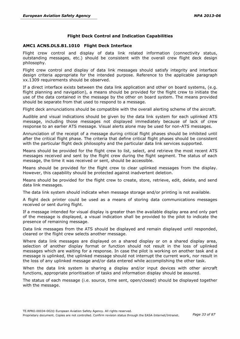
AMC1 ACNS.DLS.B1.1010 Flight Deck Interface
Flight crew control and display of data link related information (connectivity status,
outstanding messages, etc.) should be consistent with the overall crew flight deck design
philosophy.
Flight crew control and display of data link messages should satisfy integrity and interface
design criteria appropriate for the intended purpose. Reference to the applicable paragraph
xx.1309 requirements should be observed.
If a direct interface exists between the data link application and other on board systems, (e.g.
flight planning and navigation), a means should be provided for the flight crew to initiate the
use of the data contained in the message by the other on board system. The means provided
should be separate from that used to respond to a message.
Flight deck annunciations should be compatible with the overall alerting scheme of the aircraft.
Audible and visual indications should be given by the data link system for each uplinked ATS
message, including those messages not displayed immediately because of lack of crew
response to an earlier ATS message. Visual alerts alone may be used for non-ATS messages.
Annunciation of the receipt of a message during critical flight phases should be inhibited until
after the critical flight phase. The criteria that define critical flight phases should be consistent
with the particular flight deck philosophy and the particular data link services supported.
Means should be provided for the flight crew to list, select, and retrieve the most recent ATS
messages received and sent by the flight crew during the flight segment. The status of each
message, the time it was received or sent, should be accessible.
Means should be provided for the flight crew to clear uplinked messages from the display.
However, this capability should be protected against inadvertent deletion.
Means should be provided for the flight crew to create, store, retrieve, edit, delete, and send
data link messages.
The data link system should indicate when message storage and/or printing is not available.
A flight deck printer could be used as a means of storing data communications messages
received or sent during flight.
If a message intended for visual display is greater than the available display area and only part
of the message is displayed, a visual indication shall be provided to the pilot to indicate the
presence of remaining message.
Data link messages from the ATS should be displayed and remain displayed until responded,
cleared or the flight crew selects another message.
Where data link messages are displayed on a shared display or on a shared display area,
selection of another display format or function should not result in the loss of uplinked
messages which are waiting for a response. In case the pilot is working on another task and a
message is uplinked, the uplinked message should not interrupt the current work, nor result in
the loss of any uplinked message and/or data entered while accomplishing the other task.
When the data link system is sharing a display and/or input devices with other aircraft
functions, appropriate prioritisation of tasks and information display should be assured.
The status of each message (i.e. source, time sent, open/closed) should be displayed together
with the message.
Page 34
European Aviation Safety Agency NPA 2013-06
TE.RPRO.00034-002© European Aviation Safety Agency. All rights reserved.
Proprietary document. Copies are not controlled. Confirm revision status through the EASA-Internet/Intranet.
Page 34 of 87
AMC1.ACNS.DLS.B1.1011 Dual Data Link Capabilities (Dual stack)
(a) The data link system should comply with ED-154A, interoperability requirements IR-207,
IR-209, IR-210, IR-211, IR-212, IR-214, and IR-215 to ensure seamless transition
between two adjacent ATSUs, one using FANS 1/A+ and the other using ATN B1
(b) The data link system should demonstrate common accessibility to the FANS 1/A and ATN
B1 CPDLC applications. Accessibility demonstration should include common controls (i.e.
line select keys) or, where different, the potential to introduce confusion or unacceptable
flight crew workload should be evaluated.
(c) The data link system should demonstrate common control and input procedures for
retrieving and responding to FANS 1/A and ATN B1 uplink messages.
(d) The data link system should demonstrate common control and input procedures for
composing and sending FANS 1/A and ATN B1 downlink messages.
(e) The data link system should demonstrate common flight deck indications for incoming
FANS 1/A and ATN B1 messages. Where common alerting is not demonstrable, the
alerting scheme evaluate to ensure that neither confusion nor unnecessary flight crew
workload is introduced.
(f) Annunciations and indications should be clear, unambiguous, timely, and consistent with
the flight deck philosophy
(g) Flight Deck Display of Messages from either FANS 1/A or ATN B1 CPDLC Applications.
A common flight deck display should be capable of displaying messages with the same
operational intent resulting from same message elements that may be implemented
differently between FANS 1/A and ATN B1 CPDLC applications. The common format to
display FANS 1/A messages should be in accordance with the preferred format denoted in
Annex A of ED 122, which is consistent with Doc 4444, 15th Ed, and ATN B1 message
formats.
(h) Dual Stack ATS Data Link System Status Indication.
The system should provide the flight crew with a means to clearly identify the status of
different modes of the data link system that affect significant operational capability.
Examples of different modes of data link may include situations when downlink messages
are available in one airspace, but not the other; or messages that may or may not be
loadable depending on system status, i.e., ATN B1 or FANS 1/A.
(i) ATSU Connections and Handoffs:
The system should be capable of the following functions:
(1) Proper connection and termination for FANS 1/A ATSU.
(2) Proper connection and termination for ATN B1 ATSU.
(3) Transfer to next data authority (e.g., FANS 1/A ATSU to ATN B1 ATSU), in both
directions. This should include proper connection, maintenance of connection and
connection termination protocol to ensure that aircraft does not hold two
simultaneous active CPDLC connections.
(4) Ability for flight crew to manually terminate existing connection and establish new
connection, in both directions (i.e., FANS 1/A-to-ATN B1 and ATN B1-to-FANS 1/A).
(5) Ability for flight crew to verify current and next facility designation or name.
Page 35
European Aviation Safety Agency NPA 2013-06
TE.RPRO.00034-002© European Aviation Safety Agency. All rights reserved.
Proprietary document. Copies are not controlled. Confirm revision status through the EASA-Internet/Intranet.
Page 35 of 87
(j) FAA AC 20-140A provides adequate guidance related to the application interoperability,
sub-networks and performance designators. (refer to Tables 5.1 and 5.2).
ATN B1 Data link
AMC1 ACNS.DLS.B1.2000 Data Link Services
When the aircraft has no CPDLC Current Data Authority, the data link aircraft equipment
should provide crew members entering an airspace of a data link equipped ATS unit with the
capability to initiate a DLIC ‘Logon’ function (e.g. send a CMLogonRequest message) with the
applicable ATS unit, in order to identify the aircraft and initiate the use of data link services.
GM1 ACNS.DLS.B1.2000 Data Link Services
(a) Data Link Initiation Capability (DLIC) Service
The DLIC service enables the exchange of information between aircraft and ground data
link equipment necessary for the establishment of data link communications. It ensures:
(1) the unambiguous association of flight data from the aircraft with flight plan data
used by an ATS unit,
(2) the exchange of the supported air–ground application type and version information,
(3) the delivery of the addressing information of the entity hosting the application.
(b) ATC Communications Management (ACM) Service
The ACM service provides automated assistance to flight crews for conducting the
transfer of ATC communications (voice and data). It includes:
(1) the initial establishment of CPDLC with an ATS unit;
(2) the CPDLC ATC transfer instruction from one ATS unit to the next ATS unit;
(3) the CPDLC ATC instructions for a change in voice channel;
(4) the normal termination of CPDLC with an ATS unit.
(c) ATC Clearances and Information (ACL) Service
The ACL service provides flight crews with the ability to:
(1) send requests and reports to air traffic controllers;
(2) receive clearances, instructions and notifications issued by air traffic controllers to
flight crews.
(d) ATC Microphone Check (AMC) Service
The AMC service provides CPDLC ATC instructions to flight crews requesting them to
verify the status of their voice communication equipment
AMC1 ACNS.DLS.B1.2001 Protection mechanism
The data link system should comply with the following applicable ATN Baseline 1 standards:
(a) ICAO Document 9705 (Edition 2) for ICS (Sub-Volume V), ULCS (Sub-Volume IV),
CM CPDLC (Sub-Volume II) ASE requirements;
(b) EUROCAE Document ED-110B;
(c) ICAO Document 9776 and ARINC 631-6 for VDL Mode 2 multi-frequency operations.
Page 36
European Aviation Safety Agency NPA 2013-06
TE.RPRO.00034-002© European Aviation Safety Agency. All rights reserved.
Proprietary document. Copies are not controlled. Confirm revision status through the EASA-Internet/Intranet.
Page 36 of 87
The data link aircraft equipment should provide support for the CPDLC application message
integrity check mechanism , with support for ‘default checksum algorithm’ only.
AMC2 ACNS.DLS.B1.2001 Protection mechanism
Testing demonstrations could be based in two main steps:
(a) Equipment testing (done by equipment manufacturer) using adequate simulation testing
tools.
(b) System testing, at system test bench and/or at aircraft test level (either on ground or in
flight).
Equipment qualification testing data may be reused from the avionics manufacturer, provided
that full and unrestricted access to the compliance data is established and maintained.
However, the applicant remains responsible for all test data used in the course of compliance
demonstration.
AMC3 ACNS.DLS.B1.2001 Protection mechanism
Where ARINC 631-6 identifies a specific deviation from ICAO Doc 9776 (Manual on VDL Mode
2), the provisions of the former should take precedence.
ARINC 631-6 also references ARINC 750 for definition of Signal Quality Parameter (SQP)
levels. Measurements of SQP levels may be passed over the air-ground link as parameters in
the XID exchanges.
GM1 ACNS.DLS.B1.2001 Protection mechanism
EUROCAE Document ED-110B sections 3.3.5.1 and 3.3.6 mentions an ‘ATN Message Checksum
Algorithm’ (or ‘Application Message Integrity Check (AMIC)’) that does not exist in ICAO
Document 9705 Edition 2. These terms are correctly referenced in ICAO Doc 9705
PDR M60050001.
GM2 ACNS.DLS.B1.2001 Protection mechanism
Both ICAO Document 9705 and EUROCAE Document ED-110B include requirements for the
support of FIS and ADS-C applications. These two applications are not mandated for operations
in European airspace. Data link aircraft implementations are free to support these applications
and should notify their application availability in the DLIC logon function.
GM3 ACNS.DLS.B1.2001 Protection mechanism
Further guidance material from EUROCONTROL is available at Link 2000+ Programme
Websites:
http://www.eurocontrol.int/link2000/public/subsite_homepage/homepage.html.
http://www.eurocontrol.int/link2000/public/site_preferences/display_library_list_public.h
tml.
LINK2000+/ATC DATA LINK OPERATIONAL GUIDANCE, Version 5.1, Date:
01 March 2010.
LINK 2000+ Guidance to Airborne Implementers, Version 1.1, Date: 09 December 2009.
LINK2000+/FLIGHT CREW DATA LINK OPERATIONAL GUIDANCE Version 4.0, Date:
30 June 2009.
LINK2000+ Programme, Generic Interop Test Plan for Avionics - Part 1, Upper Layers
and CM/CPDLC applications, Version 2.3, Date: 15th June 2010.
Page 37
European Aviation Safety Agency NPA 2013-06
TE.RPRO.00034-002© European Aviation Safety Agency. All rights reserved.
Proprietary document. Copies are not controlled. Confirm revision status through the EASA-Internet/Intranet.
Page 37 of 87
Time
AMC1 ACNS.DLS.B1.3101 Universal Time Coordinated (UTC)
A Global Navigation Satellite System (GNSS) sensor provides an acceptable source of
synchronised UTC time.
Time synchronisation is required by ICAO Annex II, chapter 3, section 3.5 as referred by
EUROCAE Document ED-110B, section 3.3.2. It is also identified as a safety requirement in
EUROCAE Document ED-120 (e.g. SR-ACL-15).
Data link initiation capability (DLIC) service messages
AMC1 ACNS.DLS.B1.3201 DLIC Uplink Messages
Data link aircraft equipment should comply with ICAO Doc 9705 (Edition 2), section 2.1.4 and
EUROCAE Document ED-110B, section 2.2.1.
AMC1 ACNS.DLS.B1.3202 DLIC Downlink Messages
Data link aircraft equipment should comply with ICAO Doc 9705 (Edition 2), section 2.1.4 and
EUROCAE Document ED-110B, section 2.2.1.
CPDLC messages
AMC1 ACNS.DLS.B1.3301 CPDLC Uplink Messages
The data link system should comply with EUROCAE Document ED-110B section 2.2.3 and
comply with the CPDLC message syntax ICAO Doc 9705 (Edition 2), section 2.1.4.
For the sole exception of UM117, the data link system should prepare the appropriate response
downlink message to a received uplink message in compliance with EUROCAE Document
ED-110B, section 2.2.3.3 Table 2-4. Received uplink messages with response type ‘A/N’or ‘Y’
as indicated in the ‘Response’ column should be responded with either DM4 (AFFIRM) or DM5
(NEGATIVE). Received uplink messages with response type ‘R’ as indicated in the ‘Response’
column should be responded with DM3 (ROGER). When UM117 CONTACT is received, no DM89
MONITORING message should be sent.
The data link aircraft system should also handle unsupported messages (i.e. uplink message
not referenced in CS ACNS.DLS.B1.3201) as specified in EUROCAE Document ED-110B, section
3.3.7.6.
AMC2 ACNS.DLS.B1.3301 CPDLC Uplink Messages
EUROCAE Document ED-110B requires (in Table 4-3, item 6a) aircraft to send the DM89
(MONITORING [unitname] [frequency]) CPDLC message upon receipt of a UM117 (CONTACT)
or UM120 (MONITOR) CPDLC message. The sending of DM89 should be executed in response
to UM120 but not for UM117.
Page 38
European Aviation Safety Agency NPA 2013-06
TE.RPRO.00034-002© European Aviation Safety Agency. All rights reserved.
Proprietary document. Copies are not controlled. Confirm revision status through the EASA-Internet/Intranet.
Page 38 of 87
GM1 ACNS.DLS.B1.3301 Uplink Messages
The following table associates uplink CPDLC messages to the data link services.
ID Message ACM ACL AMC
UM0 UNABLE x
UM1 STANDBY x
UM3 ROGER x
UM4 AFFIRM x
UM5 NEGATIVE x
UM19 MAINTAIN [level] x
UM20 CLIMB TO [level] x
UM23 DESCEND TO [level] x
UM26 CLIMB TO REACH [level] BY [time] x
UM27 CLIMB TO REACH [level] BY [position] x
UM28 DESCEND TO REACH [level] BY [time] x
UM29 DESCEND TO REACH [level] BY [position] x
UM46 CROSS [position] AT [level] x
UM47 CROSS [position] AT OR ABOVE [level] x
UM48 CROSS [position] AT OR BELOW [level] x
UM51 CROSS [position] AT [time] x
UM52 CROSS [position] AT OR BEFORE [time] x
UM53 CROSS [position] AT OR AFTER [time] x
UM54 CROSS [position] BETWEEN [time] AND [time] x
UM55 CROSS [position] AT [speed] x
UM61 CROSS [position] AT AND MAINTAIN x
UM64 OFFSET [specifiedDistance] [direction] OF ROUTE x
UM72 RESUME OWN NAVIGATION x
UM74 PROCEED DIRECT TO [position] x
UM79 CLEARED TO [position] VIA [routeClearance] x
UM80 CLEARED [routeClearance] x
UM82 CLEARED TO DEVIATE UP TO [specifiedDistance]
[direction] OF ROUTE x
UM92 HOLD AT [position] AS PUBLISHED MAINTAIN
[level] x
UM94 TURN [direction] HEADING [degrees] x
UM96 CONTINUE PRESENT HEADING x
Page 39
European Aviation Safety Agency NPA 2013-06
TE.RPRO.00034-002© European Aviation Safety Agency. All rights reserved.
Proprietary document. Copies are not controlled. Confirm revision status through the EASA-Internet/Intranet.
Page 39 of 87
ID Message ACM ACL AMC
UM106 MAINTAIN [speed] x
UM107 MAINTAIN PRESENT SPEED x
UM108 MAINTAIN [speed] OR GREATER x
UM109 MAINTAIN [speed] OR LESS x
UM116 RESUME NORMAL SPEED x
UM117 CONTACT [unitname] [frequency] x
UM120 MONITOR [unitname] [frequency] x
UM123 SQUAWK [code] x
UM133 REPORT PRESENT LEVEL x
UM148 WHEN CAN YOU ACCEPT [level] x
UM157 CHECK STUCK MICROPHONE [frequency] x
UM159 ERROR [errorInformation] x x
UM160 NEXT DATA AUTHORITY [facility] x
UM162 SERVICE UNAVAILABLE x
UM165 THEN x
UM171 CLIMB AT [verticalRate] MINIMUM x
UM172 CLIMB AT [verticalRate] MAXIMUM x
UM173 DESCEND AT [verticalRate] MINIMUM x
UM174 DESCEND AT [verticalRate] MAXIMUM x
UM179 SQUAWK IDENT x
UM183 [freetext] x x x
UM190 FLY HEADING [degrees] x
UM196 [freetext] x
UM203 [freetext] x
UM205 [freetext] x
UM211 REQUEST FORWARDED x
UM213 [facilitydesignation] ALTIMETER [altimeter] x
UM215 TURN [direction] [degrees] x
UM222 NO SPEED RESTRICTION x
UM227 LOGICAL ACKNOWLEDGEMENT x x
UM231 STATE PREFERRED LEVEL x
UM232 STATE TOP OF DESCENT x
UM237 REQUEST AGAIN WITH NEXT UNIT x x
Page 40
European Aviation Safety Agency NPA 2013-06
TE.RPRO.00034-002© European Aviation Safety Agency. All rights reserved.
Proprietary document. Copies are not controlled. Confirm revision status through the EASA-Internet/Intranet.
Page 40 of 87
GM2 ACNS.DLS.B1.3301 Uplink Messages
The above ACL messages correspond to the common subset of ACL messages defined in
EUROCAE Document ED-120 section 5.2.1.1.5 as required by Regulation (EC) No 29/2009.
AMC1 ACNS.DLS.B1.3302 Downlink Messages
The data link system should comply with EUROCAE Document ED-110B section 2.2.3 and
comply with the CPDLC message syntax ICAO Doc 9705 (Edition 2), section 2.1.4.
For the sole exception of UM117, data link aircraft equipment should prepare the appropriate
response downlink message to a received uplink message in compliance with EUROCAE
Document ED-110B, section 2.2.3.3 Table 2-4. When UM117 CONTACT is received, no DM89
MONITORING message should be sent.
GM1 ACNS.DLS.B1.3302 Downlink Messages
The following table associates uplink messages to the data link services.
ID Message ACM ACL AMC
DM0 WILCO x x
DM1 UNABLE x x
DM2 STANDBY x x
DM3 ROGER x
DM4 AFFIRM x
DM5 NEGATIVE x
DM6 REQUEST [level] x
DM9 REQUEST CLIMB TO [level] o8
DM10 REQUEST DESCENT TO [level] O8
DM22 REQUEST DIRECT TO [position] x
DM27 REQUEST WEATHER DEVIATION UP TO
[specifiedDistance] [direction] OF ROUTE
O8
DM32 PRESENT LEVEL [level] x
DM62 ERROR [errorInformation] x x
DM63 NOT CURRENT DATA AUTHORITY x
DM66 DUE TO AIRCRAFT PERFORMANCE x
DM81 WE CAN ACCEPT [level] AT [time] x
DM82 WE CANNOT ACCEPT [level] x
DM89 MONITORING [unitname] [frequency] x
DM98 [freetext] x x
DM99 CURRENT DATA AUTHORITY x
8 See GM3 ACNS.DLS_B1.3202
Page 41
European Aviation Safety Agency NPA 2013-06
TE.RPRO.00034-002© European Aviation Safety Agency. All rights reserved.
Proprietary document. Copies are not controlled. Confirm revision status through the EASA-Internet/Intranet.
Page 41 of 87
ID Message ACM ACL AMC
DM100 LOGICAL ACKNOWLEDGEMENT x x
DM106 PREFERRED LEVEL [level] x
DM107 NOT AUTHORIZED NEXT DATA AUTHORITY x x
DM109 TOP OF DESCENT [time] x
GM2 ACNS.DLS.B1.3302 Downlink Messages
The above ACL messages correspond to the common subset of ACL messages defined in
EUROCAE Document ED-120 section 5.2.1.1.5 as required by Regulation (EC) No 29/2009.
GM3 ACNS.DLS.B1.3302 Optional ACL Downlink Messages
The data link system may also allow the sending the following ACL messages defined in
EUROCAE Document ED-120 section 5.2.1.1.5. The message syntax should also comply with
ICAO Doc 9705 (Edition 2), section 2.3.4.
ID Message
DM9 REQUEST CLIMB TO [level]
DM10 REQUEST DESCENT TO [level]
DM27 REQUEST WEATHER DEVIATION UP TO
[specifiedDistance] [direction] OF ROUTE
Data link services requirements
AMC1 ACNS.DLS.B1.4101 Data Link Initiation Capability (DLIC) Service
(a) The data link aircraft equipment DLIC logon function should comply with the aircraft
system PR-DLIC-Init-ETRCTP and PR-DLIC-Init-TT performance values, respectively
6 seconds and 4 seconds, as specified in EUROCAE Document ED-120 Table A-3.
(b) The data link aircraft equipment DLIC contact function should comply with the aircraft
system PR-DLIC-Cont-ETRCTP and PR-DLIC-Cont-TT performance values, respectively 6
seconds and 4 seconds, as specified in EUROCAE Document ED-120 Table A-3.
(c) The data link system should:
(1) not permit data link services when there are incompatible DLIC version numbers;
(2) reinitiate the service with the applicable ATSUs when any of the application or flight
information changes;
(3) insert the relevant initiation data in the initiation messages;
(4) not affect the intent of the DLIC message during processing (data entry/encoding/
transmitting/decoding/displaying).
GM1 ACNS.DLS.B1.4101 Data Link Initiation Capability (DLIC) Service
The Performance Tables in the main body of EUROCAE Document ED-120 for DLIC (Table 4-9),
ACM (Table 5-21) and ACL (Table 5-31) provide the required round-trip time (TRN) and the
allocated values for the two-way transactions.
Page 42
European Aviation Safety Agency NPA 2013-06
TE.RPRO.00034-002© European Aviation Safety Agency. All rights reserved.
Proprietary document. Copies are not controlled. Confirm revision status through the EASA-Internet/Intranet.
Page 42 of 87
A detailed allocation for Aircraft delays is provided in EUROCAE Document ED-120 Annex
A/Table A-3.
AMC1 ACNS.DLS.B1.4201 ATC Communications Management (ACM) Service
The data link system for ACM service should comply with the aircraft system PR-ACM-ETRCTP
and PR-ACM-TT performance values, respectively 6 seconds and 4 seconds, as specified in
EUROCAE Document ED-120 Table A-3.
GM1 ACNS.DLS.B1. 4201 ATC Communications Management (ACM) Service
The Performance Tables in the main body of EUROCAE Document ED-120 for DLIC (Table 4-9),
ACM (Table 5-21) and ACL (Table 5-31) provide the required round-trip time (TRN) and the
allocated values for the two-way transactions.
A detailed allocation for Aircraft delays is provided in EUROCAE Document ED-120 Annex
A/Table A-3.
AMC1 ACNS.DLS.B1.4301 ATC Clearances and Information (ACL) Service
The data link system for ACL service should comply with the aircraft system PR-ACL-ETRCTP and
PR-ACL-TT performance values, respectively 6 seconds and 4 seconds, as specified in
EUROCAE Document ED-120 Table A-3.
GM1 ACNS.DLS.B1.4301 ATC Clearances and Information (ACL) Service
The Performance Tables in the main body of EUROCAE Document ED-120 for DLIC (Table 4-9),
ACM (Table 5-21) and ACL (Table 5-31) provide the required round-trip time (TRN) and the
allocated values for the two-way transactions.
A detailed allocation for Aircraft delays is provided in EUROCAE Document ED-120
Annex A/Table A-3.
Interoperability requirements
AMC1 ACNS.DLS.B1.4531 Network Layer Requirements
The ATN Router should comply with ICAO Document 9705 (Edition 2), sections 5.2.4.1, 5.2.4.3
with an IDRP Hold Time value of 900 seconds.
GM1 ACNS.DLS.B1.4531 Network Layer Requirements
Compression Schemes
Airborne ATN Router may implement several distinct, yet complementary, compression
schemes.
Airborne ATN Routers should support the CLNP Header Compression (also known as ‘LREF
Compression’). Other compression schemes in ICS are optional.
In addition to the CLNP Header Compression, data link ATN Routers that claims support for
optional DEFLATE compression should also support ICAO PDU M0070002 (‘Interoperability
impact when deflate compression is used. Non-compliance with Zlib’).
AMC1 ACNS.DLS.B1.4541 Transport Layer Requirements
The ATN End System of the data link aircraft equipment should comply with the Transport
Protocol Class 4 specified in ICAO Document 9705 (Edition 2), Sub-volume V, section 5.5.2.
The data link aircraft equipment should implement Transport Protocol Class 4 parameter
settings in accordance with the following table:
Page 43
European Aviation Safety Agency NPA 2013-06
TE.RPRO.00034-002© European Aviation Safety Agency. All rights reserved.
Proprietary document. Copies are not controlled. Confirm revision status through the EASA-Internet/Intranet.
Page 43 of 87
Scope Parameter Definition Value
Inactivity Inactivity time (I) A bound for the time after which a
transport entity will, if it does not
receive a Transport Protocol Data
Unit (TPDU), initiate the release
procedure to terminate the
transport connection.
360 sec
Re-transmission Retransmission
time (T1)
A bound for the maximum time the
transport entity will wait for
acknowledgement before re-
transmitting a TPDU.
The retransmission time is adaptive.
Initial value
30 sec
Maximum
Retransmission
(N)
Maximum number of TPDU
retransmissions.
7
Window Window time (W) A bound for the maximum time a
transport entity will wait before
retransmitting up-to-date window
information.
120 sec
Flow Control Local
Acknowledgement
delay (Al)
A bound for the maximum time
which can elapse between the
receipt of a TPDU by the local
transport entity from the network
layer and the transmission of the
corresponding acknowledgement.
1 sec
GM1 ACNS.DLS.B1.4541 Transport Layer Requirements
Transport Protocol Classes
ICAO Doc 9705 (Edition 2), Sub-volume V, section 5.5 identifies both Connection Oriented and
Connection-Less Transport Protocols (as specified in, respectively, ISO/IEC 8073 for COTP and
ISO/IEC 8602 for CLTP). The only mandated support is for COTP (i.e. CLTP support is not
required).
In addition, ISO/IEC 8073 identifies 5 distinct possible implementations for COTP support,
ranging from Class 0 (the less constraining to implement, but also the less reliable) to Class 4
(most reliable). The fifth Class, i.e. COTP Class 4 (also known as ’TP4’), is the only mandated
implementation (all other implementations classes are useless for the ATN COTP support).
Transport Protocol Classes
In the ATN Baseline 1 SARPS (i.e. Doc 9705, Edition 2), the Transport Class 4 - as known as
TP4 - is as specified in ISO 8073, that mandates support for a 16-bits checksum. Such
checksum is considered to be insufficient to detect, and thus compensate, all potential miss
deliveries of CLNP Packets by the underlying network routers. The analysis that concluded of
TP4 inability to detect and compensate all CLNP miss deliveries is available in ICAO PDR
M00040002. The use of a 32-bits long checksum is identified as a solution to address this
potential issue.
AMC1 ACNS.DLS.B1.4551 Session Layer Requirement
Page 44
European Aviation Safety Agency NPA 2013-06
TE.RPRO.00034-002© European Aviation Safety Agency. All rights reserved.
Proprietary document. Copies are not controlled. Confirm revision status through the EASA-Internet/Intranet.
Page 44 of 87
(a) The ATN End System of the data link aircraft equipment should support a Session
Protocol as specified in ICAO Doc 9705 (Edition 2), Sub-Volume IV, section 4.4 including
the ISO/IEC 8327 Technical Corrigendum 1 (2002), listed in the following table.
Value (Hex) Abbreviation Full SPDU Name
E8 SCN Short Connect
F0 SAC Short Accept
D8 SACC Short Accept Continue
E0-E3 SRF Short Refuse
E0: TC retained, transient refusal
E1: TC retained, persistent refusal
E2: TC released, transient refusal
E3: TC released, persistent refusal
A0 SRFC Short Refuse Continue
(b) The ATN End System Session Protocol of the data link system should make use of the
value ‘E3’ to encode the Short Refuse (SRF) SPDU.
AMC1 ACNS.DLS.B1.4561 Presentation Layer Requirement
(a) The ATN End System of the data link aircraft equipment should support a Presentation
Protocol as specified in ICAO Doc 9705 (Edition 2), Sub-Volume IV, section 4.5, and
listed in the following table:
Value
(Hex)
Abbreviation Full PPDU Name
02 SHORT-CP Short Presentation Connect, unaligned PER
02 SHORT-CPA Short Presentation Connect Accept, unaligned PER
x2 SHORT-CPR Short Presentation Connect Reject
Where x = reason code:
02: presentation-user
12: reason not specified (transient)
22: temporary congestion (transient)
32: local limit exceeded (transient)
42: called presentation address unknown (permanent)
52: protocol version not supported (permanent)
62: default context not supported (permanent)
72: user data not readable (permanent)
(b) The ATN End System Presentation Protocol of the data link aircraft equipment should
make use of the value ‘02’ to encode the SHORT-CPR PPDU.
AMC1 ACNS.DLS.B1.4571 Application Layer Requirements
(a) The ATN End System of the data link system should support an ATN Convergence
Function compliant with ICAO Doc 9705 (Edition 2), Sub-volume IV, section 4.3.
(b) The ATN End System of the data link system should support an ATN Association Control
Service Element (ACSE) compliant with ICAO Doc 9705 (Edition 2), Sub-volume IV,
section 4.6.
Page 45
European Aviation Safety Agency NPA 2013-06
TE.RPRO.00034-002© European Aviation Safety Agency. All rights reserved.
Proprietary document. Copies are not controlled. Confirm revision status through the EASA-Internet/Intranet.
Page 45 of 87
GM1 ACNS.DLS.B1.4571 Application Layer Requirements
From an OSI perspective, the ATN Application layer is composed of three distinct parts:
Layer 7a, that includes all application-independent services (Convergence Function +
ACSE).
Layer 7b, that includes all application-dependent service elements (such as the CPDLC-
ASE).
Layer 7c, that includes applications (such as the CPDLC application, that uses CPDLC-ASE
for its communications with ground-based systems).
Page 46
European Aviation Safety Agency NPA 2013-06
TE.RPRO.00034-002© European Aviation Safety Agency. All rights reserved.
Proprietary document. Copies are not controlled. Confirm revision status through the EASA-Internet/Intranet.
Page 46 of 87
SUBPART E — OTHERS
SECTION 1 – TERRAIN AWARENESS WARNING SYSTEM (TAWS)
GM1 ACNS.TAWS.1000 Applicability
CS-ACNS.TAWS airworthiness requirements are not suitable to allow the use of TAWS for
navigation or for mitigation of navigation system failures.
AMC1 ACNS.TAWS.1010 TAWS equipment approval
The Class A or Class B TAWS equipment should be approved in accordance with ETSO-C151b
and ETSO-C92c (for the GPWS functions).
AMC1 ACNS.TAWS.2010 Required functions
Note: An example of an acceptable TAWS installation is provided at Appendix 2.
(a) For the voice call out a predetermined altitude of 500 ft. has been found acceptable.
However, another altitude may be allowed when a call-out at 500 ft. would interfere with
other call outs
(b) For Class B equipment the predetermined altitude voice callout is based upon barometric
height above runway elevation.
Note: The nearest runway elevation may be used for this purpose.
(c) TAWS equipment may compute Barometric Altitude Rate using an Instantaneous Vertical
Speed Indicator (IVSI) or an inertial smoothed vertical speed indicator. An alternative
means, with demonstrated equal or better accuracy, may be used in lieu of barometric
altitude rate (accuracy specified in ETSO-C10b, Altimeter, Pressure Actuated, Sensitive
Type, or later revisions) and/or altimeter altitude (accuracy specified in ETSO-2C87 (Low
range radio altimeters) - or later revisions) to meet the warning requirements described
in RTCA Document No. DO-161A. In addition, ETSO-C106 for Air Data Computers may be
used as an alternative means of compliance with this provision.
AMC 2 ACNS.TAWS.2010 Required functions
In case of an intentional descent an awareness check at a predefined altitude (typically 500 ft)
should be provided by the TAWS or by an operational procedure.
In case of an unintentional descent the TAWS should provide an automatic call out when
descending through a predefined altitude (typically 500ft).
For a Class B TAWS in order to compensate for the lack of ‘excessive closure rate to terrain ‘
function the predefined altitude should be 500ft.
AMC1 ACNS.TAWS.2020 FLTA function requirements
(a) The TAWS lateral search area should be less than the protected area defined by ICAO
PANS OPS 8168, volume 2 to prevent nuisance alerts.
Note: The required obstacle (terrain) clearance (ROC) have been used to define the minimum requirements for obstacle/terrain clearance (RTC) appropriate to the FLTA function
(b) As an alternate to the stepped down reduction from the terminal to approach phase in CS
ACNS.TAWS 2020 Table 1 , a linear reduction of the RTC as the aeroplane comes closer
Page 47
European Aviation Safety Agency NPA 2013-06
TE.RPRO.00034-002© European Aviation Safety Agency. All rights reserved.
Proprietary document. Copies are not controlled. Confirm revision status through the EASA-Internet/Intranet.
Page 47 of 87
to the nearest runway is allowed, providing the requirements of CSACNS.TAWS 2020
Table 1 are met.
(c) During the visual segment of a normal instrument approach (typically about 1 NM from
the runway threshold), the RTC should be defined/reduced to minimise nuisance alerts.
(d) The RTC values can be reduced slightly for descending flight conditions to accommodate
the dynamic conditions and pilot response times.
(e) The FLTA search volume should vary as a function of phase of flight, distance from
runway, and the required terrain clearance.
GM1 ACNS.TAWS.2030 PDA function requirements
The purpose of the PDA alert is to increase pilot’s awareness. Therefore ‘significantly below’
means the point below the profile where the pilot would normally initiate a Go Around (e.g. for
ILS this would correspond to 1 dot deviation).
AMC1 ACNS.TAWS.2040 Class A TAWS inhibition
(a) An automatic inhibit capability is acceptable if it uses the information of the TAWS as a
failure monitoring function.
Note: The alternate manual inhibit functionality will allow pilots to disable the TAWS FLTA and PDA alerts without removing the terrain display when landing at a site not included in the database or landing at a site that generates known nuisance alerts.
(b) If an automatic inhibition is provided and it automatically inhibits the FLTA alerts, PDA
alerts and terrain display then the manual inhibit may be designed to only inhibit aural
and visual alerts.
(c) A separate guarded control may be provided to inhibit GPWS alerts based on flaps being
other than the landing configuration.
AMC1 ACNS.TAWS.2050 Terrain information display
(a) Terrain data should be displayed in the normal field of view. Terrain that is more than
2000 ft below the aeroplane’s elevation need not be depicted.
(b) Terrain, obstacle and alerting information could be displayed on a weather radar, an
Electronic Flight Instrument System display, or other compatible display system available
on the flight deck. In this case, the TAWS information should be displayed in a manner
consistent with other information (e.g. range, colour coding, symbology).
(c) When Auto-range switching is provided, an auto-ranging display should be designed so
that it is evident to the flight crew that the range has been automatically selected. The
range selected for auto-ranging should clearly depict the threat on the display. Manual
reversion to a selected range should be simple.
AMC1 ACNS.TAWS.2060 Aural and visual alerts
(a) Table 1 below contains a set of acceptable TAWS alerts. In addition to this minimum set,
other voice alerts may be provided.
Alert Condition Caution Warning
Ground proximity
Altitude Loss after
Take-off
Visual Alert
Amber text message that is
obvious, concise, and must be
consistent with the Aural
Visual Alert
None required
Aural Alert
None Required
Page 48
European Aviation Safety Agency NPA 2013-06
TE.RPRO.00034-002© European Aviation Safety Agency. All rights reserved.
Proprietary document. Copies are not controlled. Confirm revision status through the EASA-Internet/Intranet.
Page 48 of 87
Alert Condition Caution Warning
Class A & Class B
equipment
message
Aural Alert
‘Don’t Sink’ and ‘Too Low Terrain’
Ground Proximity
Envelope 1 (Not in
Landing Configuration)
Class A equipment
Visual Alert
Amber text message that is
obvious, concise, and must be
consistent with the Aural
message
Aural Alert
‘Too Low Terrain’ and ‘Too Low
Gear’
Visual Alert
None required
Aural Alert
None Required
Ground Proximity
Envelope 2 Insufficient
Terrain Clearance
(Landing and Go
around configuration)
Class A equipment
Visual Alert
Amber text message that is
obvious, concise, and must be
consistent with the Aural
message
Aural Alert
‘Too Low Terrain’ and ‘Too Low
Flaps’
Visual Alert
None required
Aural Alert
None Required
Ground Proximity
Envelope 4C
Insufficient Terrain
Clearance (Take-off
configuration)
Class A equipment
Visual Alert
Amber text message that is
obvious, concise, and must be
consistent with the Aural
message
Aural Alert
‘Too Low Terrain’
Visual Alert
None required
Aural Alert
None Required
Ground Proximity
Excessive Glide Slope
Deviation
Class A equipment
Visual Alert
Amber text message that is
obvious, concise, and must be
consistent with the Aural
message
Aural Alert
‘Glide Slope’
Visual Alert
None required
Aural Alert
None Required
Ground Proximity
Advisory Voice Call Out
Class A & Class B
equipment
Visual Alert
None Required
Aural Alert
‘Five Hundred’
Visual Alert
None required
Aural Alert
None Required
Reduced Required
Terrain Clearance
Class A & Class B
equipment
Visual Alert
Amber text message that is
obvious, concise, and must be
consistent with the Aural
message
Aural Alert
Minimum selectable Voice Alerts:
Visual Alert
Red text message that is
obvious, concise and must be
consistent with the Aural
message
Aural Alert
Minimum selectable Voice Alerts:
Page 49
European Aviation Safety Agency NPA 2013-06
TE.RPRO.00034-002© European Aviation Safety Agency. All rights reserved.
Proprietary document. Copies are not controlled. Confirm revision status through the EASA-Internet/Intranet.
Page 49 of 87
Alert Condition Caution Warning
‘Caution, Terrain; Caution,
Terrain’ and ‘Terrain Ahead;
Terrain Ahead’
‘Caution, Terrain; Terrain; Pull-
Up, Pull-Up’ and ‘Terrain Ahead,
Pull-Up; Terrain Ahead, Pull-Up’
Imminent Impact with
Terrain
Class A & Class B
equipment
Visual Alert
Amber text message that is
obvious, concise, and must be
consistent with the Aural
message
Aural Alert
Minimum selectable Voice Alerts:
‘Caution, Terrain; Caution,
Terrain’ and ‘Terrain Ahead;
Terrain Ahead’
Visual Alert
Red text message that is
obvious, concise and must be
consistent with the Aural
message
Aural Alert
Minimum selectable Voice Alerts:
‘Caution, Terrain; Terrain; Pull-
Up, Pull-Up’ and ‘Terrain Ahead,
Pull-Up; Terrain Ahead, Pull-Up’
Premature Descent
Alert (PDA)
Class A & Class B
equipment
Visual Alert
Amber text message that is
obvious, concise, and must be
consistent with the Aural
message
Aural Alert
‘Too Low Terrain’
Visual Alert
None required
Aural Alert
None Required
Ground Proximity
Envelope 1, 2 or 3
Excessive Descent Rate
Class A & Class B
equipment
Visual Alert
Amber text message that is
obvious, concise, and must be
consistent with the Aural
message
Aural Alert
‘Sink Rate’
Visual Alert
Red text message that is
obvious, concise and must be
consistent with the Aural
message
Aural Alert
‘ Pull-Up’
Ground Proximity
Excessive Closure Rate
(Flaps not in Landing
Configuration)
Class A equipment
Visual Alert
Amber text message that is
obvious, concise, and must be
consistent with the Aural
message
Aural Alert
‘Terrain- Terrain’
Visual Alert
Red text message that is
obvious, concise and must be
consistent with the Aural
message
Aural Alert
‘ Pull-Up’
Ground Proximity
Excessive Closure Rate
(Landing
Configuration)
Class A equipment
Visual Alert
Amber text message that is
obvious, concise, and must be
consistent with the Aural
message
Aural Alert
‘Terrain- Terrain’
Visual Alert
None required
Aural Alert
‘ Pull-Up’ - for gear up
None required - for gear down
TABLE 1: Visual and aural alerts
(b) If a two tone sweep (‘Whoop Whoop’) is used then the complete cycle of the two tone
sweeps plus annunciation may be extended from ‘1.4’ to ‘2’ seconds.
Note: GPWS alerting thresholds may be adjusted or modified to be more compatible with the FLTA
alerting functions and to minimize GPWS nuisance alerts.
Page 50
European Aviation Safety Agency NPA 2013-06
TE.RPRO.00034-002© European Aviation Safety Agency. All rights reserved.
Proprietary document. Copies are not controlled. Confirm revision status through the EASA-Internet/Intranet.
Page 50 of 87
(c) Parameters such as airspeed, groundspeed barometric altitude rate should be included in
the logic that determines basic GPWS alerting time.
(d) GPWS alerting thresholds may be adjusted or modified to be more compatible with the
FLTA alerting functions and to minimize GPWS nuisance alerts.
(e) Consideration should be given to presenting voice announcements at a pre-set level via
headsets when they are in use.
AMC1 ACNS.TAWS.3020 Terrain and airport information
An airport and terrain database used by the TAWS should be compliant with EUROCAE
ED-98 () – User Requirements for Terrain and Obstacle Data.
Note: Other technologies could be considered to provide the required terrain and airport information.
The manufacturer of the TAWS system should present the development and methodology used
to validate and verify the terrain, obstacle and airport information in compliance with EUROCAE
ED76/RTCA DO200A.
AMC1 ACNS.TAWS.3030 Positioning information
(a) The TAWS positioning information can be generated internally to the TAWS (e.g. GPS
receiver) or acquired by interfacing to other installed avionics on the aeroplane (e.g.
FMS).
(1) For Class A TAWS an RNAV system may be used as an aeroplane horizontal position
sensor provided that:
it has been approved for navigation in accordance with ETSO-C115() or ETSO-
C129c or ETSO-C145() or ETSO-C146() or ETCO-C196a; or
it satisfies FAA AC 20-138.
(2) For Class A and B TAWS a GNSS sensor may be used as an aeroplane horizontal
position sensor provided that it is compliant with ETSO-C196 or ETSO-C145.
Note: For TAWS relying on GNSS sensor, the TAWS design should consider the use of other horizontal position sensors to ensure TAWS availability in case of GNSS failures
(3) Equipment that uses a GNSS internal to the TAWS for horizontal position
information, and that are capable of detecting a positional error that exceeds the
appropriate alarm limit for the particular phase of flight in accordance with ED-72A
is considered acceptable.
(4) Vertical position for TAWS may come from a barometric source such as an altimeter
or an air data computer, or from a geometric source, such as GNSS provided that:
the barometric altitude equipment is approved in accordance with ETSO-C106
Air data computer or ETSO-C10b Altimeter, Pressure Actuated, Sensitive
Type;
the radio altimeter equipment is approved in accordance with ETSO-2C87
Low-Range Radio Altimeter;
the vertical velocity equipment is compliant with ETSO-C8 Vertical Velocity
Instruments or ETSO-C105 Air Data Computer;
the GNSS equipment is approved in accordance with:
o ETSO-C145, Airborne Navigation Sensors Using the Global Positioning
System Augmented by the Satellite Based Augmentation System; or
Page 51
European Aviation Safety Agency NPA 2013-06
TE.RPRO.00034-002© European Aviation Safety Agency. All rights reserved.
Proprietary document. Copies are not controlled. Confirm revision status through the EASA-Internet/Intranet.
Page 51 of 87
o ETSO-C146, Stand-Alone Airborne Navigation Equipment Using the
Global Positioning System Augmented by the Satellite Based
Augmentation System.
Note: Designs that cross check barometric and geometric altitude are recommended.
(b) When the GPS alert limit is activated, the GPS computed position is considered unsuitable
for TAWS, and a TAWS unsuitability indication should be given.
(c) Geometric altitude should be enabled if the system has the facility.
AMC1 ACNS.TAWS.4010 Prioritisation schemes
TAWS prioritisation schemes should be compliant with the content of Table 2:
Priority Description Alert Level Comments
1 Reactive Windshear Warning W
2 Sink Rate Pull-Up Warning W Continuous
3 Excessive Closure Pull-Up Warning W Continuous
4 RTC Terrain Warning W
5 V1 Callout A
6 Engine Fail Callout W
7 FLTA Pull-Up Warning W Continuous
8 PWS Warning W
9 RTC Terrain Caution C Continuous
10 Minimums A
11 FLTA Caution C 7 s period
12 Too Low Terrain C
13 PDA ‘Too Low Terrain’ Caution C
14 Altitude Callouts A
15 Too Low Gear C
16 Too Low Flaps C
17 Sink Rate C
18 Don’t Sink C
19 Glideslope C 3 s period
20 PWS Caution C
21 Approaching Minimums A
22 Bank Angle C
23 Reactive Windshear Caution C
Mode 6 TCAS RA (‘Climb’, ‘Descent’, etc) W continuous
Mode 6 TCAS TA (‘Traffic, Traffic’) C Continuous
Page 52
European Aviation Safety Agency NPA 2013-06
TE.RPRO.00034-002© European Aviation Safety Agency. All rights reserved.
Proprietary document. Copies are not controlled. Confirm revision status through the EASA-Internet/Intranet.
Page 52 of 87
Table 2: Alert Prioritization Scheme
Note 1: These alerts can occur simultaneously with TAWS voice callout alerts.
Note 2: W= Warning, C= Caution, A= Advisory.
TAWS internal priority alerting scheme should be compliant with the content of Table 3 below
Priority Description
1 Sink Rate Pull-Up Warning
2 Terrain Awareness Pull-Up warning
3 Terrain Awareness Caution
4 PDA ‘Too Low Terrain’ Caution
5 Altitude Callouts ‘500’
6 Sink Rate
7 Don’t Sink (Mode 3)
TABLE3: TAWS Internal Alert Prioritization Scheme
AMC1 ACNS.TAWS.4020 Pop-up mode
For dual displays, the pop-up function can be inhibited if terrain is already presented on at
least one display.
If TAWS and the Predictive Windshear System share the same display and an automatic pop-
up function is employed, the display priorities indicated in Table 4 are recommended:
Priority Description
Highest Terrain Awareness Warning
Predictive Windshear Warning
Terrain Awareness Caution
Predictive Windshear Caution
Normal Terrain Display
Lowest Weather Radar Display
TABLE 4: Alert display priorities
If the TAWS system provides alerting for obstacle threats, the priority for warning and cautions
should be the same as those for terrain.
Page 53
European Aviation Safety Agency NPA 2013-06
TE.RPRO.00034-002© European Aviation Safety Agency. All rights reserved.
Proprietary document. Copies are not controlled. Confirm revision status through the EASA-Internet/Intranet.
Page 53 of 87
APPENDIX 1: TAWS INSTALLATIONS TESTING GUIDANCE MATERIAL
General Testing:
(a) Most of the testing of a TAWS installation can be achieved by ground testing that verifies
system operation, interfaces between affected aeroplane systems, correct warning
prioritisation, and freedom from unwanted interaction or interference.
(b) The use of the TAWS as an integrated part of the aeroplane flight deck should be
demonstrated. The TAWS should be shown to be compatible with the operation of the
installed navigation systems including paper charts, the airborne collision and avoidance
system (ACAS), the windshear warning system, and the weather radar.
(c) The tests should evaluate the effects of sensor failure on TAWS operation.
(d) Flight testing should be carried out to evaluate overall operation, compatibility between
TAWS, warning systems, navigation systems, and displays, freedom from unwanted
interference, and to assess, during adverse flight conditions, instrument visibility, display
lighting, sound levels and intelligibility of voice announcements, and the effects of
electrical transients.
(e) Adequate flight testing to evaluate the terrain display can be conducted while verifying all
the other required TAWS functions. Emphasis could be placed on showing compliance
with CS ACNS.TAWS requirements during normal aeroplane manoeuvres for all phases of
flight. Pop-up and auto-ranging features could be evaluated if applicable. Sustained turns
could be performed, to evaluate for example symbol stability, flicker, jitter, display
update rate, readability, the use of colour to depict relative elevation data, caution and
warning alerts, and overall suitability of the display.
GPWS Testing:
(a) Flight testing to verify the proper operation of Basic GPWS functions can be conducted in
any area where the terrain elevation is known to the flight crew. The following
information provides an example of guidance for conducting flight tests to verify the
proper operation of each GPWS function.
(1) Excessive Rate of Descent. Descents toward near level terrain are recommended if
they provide the best results and ease of correlation with DO161A envelopes. This
test verifies the operation of barometric altitude (and the corresponding
computation of barometric altitude rate) and radio altitude.
(2) Excessive Closure Rate To Terrain. It is recommended that one level test run at an
altitude between 500 and 1000 ft above the terrain elevation be conducted. This
test will verify the proper installation of the radio altimeter.
(3) Negative Climb Rate or Altitude Loss After take-off. If it is adequate this test can be
conducted immediately after take-off before climbing above 700 AGL or above
runway elevation. This test verifies the proper operation of barometric altitude,
barometric altitude rate and radio altitude.
(4) Flight Into Terrain When Not In Landing Configuration. If it is adequate this test can
be conducted while on a visual approach to a suitable runway. This test verifies the
proper installation of barometric altitude, barometric altitude rate and radio altitude
as well as the gear and flap sensor inputs to TAWS.
Page 54
European Aviation Safety Agency NPA 2013-06
TE.RPRO.00034-002© European Aviation Safety Agency. All rights reserved.
Proprietary document. Copies are not controlled. Confirm revision status through the EASA-Internet/Intranet.
Page 54 of 87
(5) Excessive Downward Deviation from an ILS Glideslope. This test should be
conducted during an ILS approach. This test will verify the proper operation of the
ILS Glideslope input to TAWS.
(6) Voice Callout ‘Five Hundred ft. This test can be conducted during an approach to a
suitable runway. This test will verify the proper operation of barometric altitude,
radio altitude, and height above terrain as determined by either radio altitude.
(7) Go-around. This test can be performed to confirm that nuisance alerts do not occur
during normal go-around manoeuvres.
FLTA Testing:
(a) Flight testing to verify the proper operation of the FLTA function can be conducted in an
area where the terrain or obstacle elevation for the test runs is known within
approximately 300 ft. Two test runs can be performed:
(1) In level flight at approximately 500 ft above the terrain/obstacle of interest.
(2) While descending toward the terrain/obstacle of interest.
(b) In each test case, the terrain display, the aural and visual alerts, the navigation source
input, and the terrain data base can each be evaluated if necessary. Confirmation that
the specific terrain cells do generate the required alert can also be evaluated if
necessary.
NOTE: To conduct the test as described, the chosen terrain could be for example at least 15 NM from the nearest airport. If this is not practical, the fly-over altitude will have to be lowered, for example to 300 ft or less above the terrain/obstacle in order to generate a TAWS alert.
PDA Testing:
(a) Flight testing to verify the proper operation of the PDA function can be conducted in any
airport area within an adequate distance of the nearest runway for example, 10 NM. The
aeroplane should be configured for landing at an adequate height for example, 1500 ft
AGL, along the final approach segment of the runway at an adequate distance from the
runway, for example, 10 NM.
(b) At a suitable point, a normal flight path angle descent, for example, three degrees can be
initiated and maintained until the PDA alert occurs. This test may exercise also, if
necessary the 500 ft voice callout.
The adequacy of the PDA aural alert should be verified during this test. If necessary, this
test could verify the adequacy of the airport data base, the navigation source input and
the barometric and/or radio altitude inputs to TAWS.
NOTE: The area in the vicinity of the runway selected for this test should be relatively free from terrain and obstacles to preclude activation of the FLTA function. Approximately level terrain along
the final approach segment will exercise the PDA function.
(c) Flight tests should be conducted to verify that conditions at 1000 ft AGL within 10 -15 NM
of the nearest airport the TAWS system does not generate alerts.
Page 55
European Aviation Safety Agency NPA 2013-06
TE.RPRO.00034-002© European Aviation Safety Agency. All rights reserved.
Proprietary document. Copies are not controlled. Confirm revision status through the EASA-Internet/Intranet.
Page 55 of 87
APPENDIX 2: EXAMPLE OF AN ACCEPTABLE TAWS INSTALLATION
An example of an acceptable installation is a single approved TAWS comprising the following
components or inputs:
(a) A single terrain awareness and warning computer.
(b) A single radio altimeter sensor.
(c) A single air data system.
(d) An ILS/GBAS/SBAS/MLS/MMR receiver for Class A TAWS only.
(e) An interface with the landing gear and flaps.
(f) A roll attitude sensor.
(g) An accurate source of aeroplane position e.g. Flight Management System (FMS), or a
Global Positioning System (GPS) or both.
(h) Where operations are reliant on the use of QFE, an adequate means of determining the
altitude should be provided.
(i) A terrain data base covering the expected region of normal operations, together with a
means of updating the stored data and to check its validity (by effective date and
geographical region).
(j) A terrain awareness display.
(k) A loudspeaker for voice announcements.
(l) Consideration should be given to presenting voice announcements via headsets at a
preset level particularly where active noise-reducing or noise cancelling headsets are
used.
(m) Indication of TAWS and sensor failures.
(n) Indication that the TAWS is operating in Basic GPWS mode only.
(o) A means to initiate the TAWS self-test function on the ground and where feasible in the
air.
(p) An interface with the flight recording system to record TAWS alerts and inhibition of FLTA
or PDA functions.
(q) Indication to the flight crew where geographical regions of operation or other factors
which adversely affect system performance to the extent that the TAWS may be
potentially misleading and should not be relied up. If this indication is not practicable, a
flight crew procedure may be used to determine whether the navigation system accuracy
is acceptable for continued use of the TAWS.
(r) A means for the flight crew to inhibit the FLTA and PDA functions together with
appropriate annunciation of the inhibited condition.
(s) A display with a means for the flight crew to select or deselect the terrain information. An
automatic pop-up mode may be used with a simple means to deselect the terrain
information after an automatic pop-up.
Page 56
European Aviation Safety Agency NPA 2013-06
TE.RPRO.00034-002© European Aviation Safety Agency. All rights reserved.
Proprietary document. Copies are not controlled. Confirm revision status through the EASA-Internet/Intranet.
Page 56 of 87
SECTION 2 – REDUCED VERTICAL SEPARATION MINIMUM (RVSM)
AMC1 ACNS.RVSM.1010 RVSM system
(a) When Static Source Error Corrections (SSEC) are required they should be embedded
within the altimetry system.
Note: The design aim for SSEC is to correct for the residual static source error, compatible with the RVSM performance requirements.
(b) For RVSM systems with SSEC, an equivalent SSEC may be applied to the altitude control
signal.
AMC1 ACNS.RVSM.2000 Required functions
The signal representing the altitude alerting system may be used either directly, or combined
with other sensor signals. The signal may be an altitude deviation signal, relative to the
selected altitude, or a suitable absolute altitude signal.
AMC1 ACNS.RVSM.3020 RVSM system performance requirement
If the design and characteristics of the aircraft and its altimetry system are such that the
performance requirements are not satisfied by the location and geometry of the static sources
alone, then suitable Static Source Error Corrections should be applied automatically within the
altimetry system.
AMC1 ACNS.RVSM.3030 Altimetry system accuracy
To demonstrate the compliance with ASE performances the following steps should be
performed:
(a) Group and Non Group determination:
(1) Aircraft should have been constructed to a nominally identical design and be
approved on the same Type Certificate (TC). Aircraft constructed or modified to a
TC amendment, Supplemental TC may be considered as part of the same group
providing that all height keeping performance characteristics as described in the
following paragraphs remain the same.
(2) The static system of each aircraft should be nominally identical. The Static Source
Error and any applied SSE Corrections should be the same for all aircraft of the
group.
(3) The operational flight envelope should be the same.
(4) The avionics units installed on each aircraft to meet the minimum RVSM
performance requirements should demonstrate equivalent height keeping system
performance in relation to; altitude control, altitude reporting and the interface to
the altimetry system sensors. Altimetry system integrity should be the same with
equivalent reliability, degradation and failure rates.
If an airframe does not meet the conditions above to qualify as a member of a
Group, or is presented as an individual airframe for approval, then it will be
considered as a non-group aircraft for the purposes of RVSM approval.
(b) RVSM Flight envelopes boundaries (Full and Basic)
The RVSM full flight envelope boundaries should be defined based on the RVSM airspace
and aircraft or group aircraft characteristics as summarised in Table 1.
The RVSM basic envelope boundaries are similar to the ones of the full flight envelope,
however, the upper Mach boundary may be lower than the one of the full flight envelope
but not be less than the Long Range Cruise Mach Number plus 0.04 Mach, unless limited
Page 57
European Aviation Safety Agency NPA 2013-06
TE.RPRO.00034-002© European Aviation Safety Agency. All rights reserved.
Proprietary document. Copies are not controlled. Confirm revision status through the EASA-Internet/Intranet.
Page 57 of 87
by available cruise thrust, buffet or other flight limitations. This reduction in upper Mach
value would typically apply to cases where airspeeds could be limited to the range of
airspeeds over which the aircraft can reasonably be expected to operate most frequently.
Condition Lower Boundary is defined by Upper Boundary is defined by
Flight Level FL 290 The lower of :
FL 410
Aircraft maximum certified
altitude
Altitude limited by: cruise
thrust; buffet; other aircraft
flight limitations
Mach or Speed The lower of:
Maximum endurance (holding
speed)
Manoeuvre speed
The lower of :
MMO/VMO
Speed limited by cruise thrust;
buffet; other aircraft flight
limitations
Gross Weight The lowest gross weight
compatible with operations in
RVSM airspace
The highest gross weight
compatible with operations in
RVSM airspace
TABLE 1 - Full RVSM envelope boundaries
(c) Test performance results presentation:
The test performance results may be presented on a single chart if the RVSM flight
envelope is plotted using W/δ (weight divided by atmospheric pressure ratio) versus
Mach number.
Note: This is due to the relationship between W/δ and the fundamental aerodynamic variables M and lift coefficient as shown below.
W/δ = 1481.4CLM2 SRef, where:
δ = ambient pressure at flight altitude divided by sea level standard pressure of 1013.25 hPa
W/δ = Weight over Atmospheric Pressure Ratio
CL = Lift Coefficient
M = Mach number
SRef = Reference Wing Area
Since δ is a fixed value for a given altitude, weight can be obtained for a given condition by simply multiplying the W/δ value by δ. Furthermore, over the RVSM altitude range, it is a good
approximation to assume that position error is uniquely related to Mach number and W/δ for a given aircraft.
(d) Error budget
The demonstration of compliance with the RVSM performance criteria should include a
justification of the contribution of all significant errors to the ASE (Error Budget).
Appendix 1 provides guidance supporting the development of such justification.
Page 58
European Aviation Safety Agency NPA 2013-06
TE.RPRO.00034-002© European Aviation Safety Agency. All rights reserved.
Proprietary document. Copies are not controlled. Confirm revision status through the EASA-Internet/Intranet.
Page 58 of 87
Note: A trade-off may be made between the various error sources which contribute to
ASE (e.g.: in the case of an aircraft group approval, the smaller the mean of the group
and the more stringent the avionics standard, the larger the available allowance for the
SSE variations). The ASE performance demonstration should consider this ASE trade off.
(e) ASE Flight Calibration Methods
Where flight calibrations are used to quantify or verify altimetry system performance
they should be accomplished by any of the following methods. Flight calibrations should
be performed only when appropriate ground checks have been completed. Uncertainties
in application of the method will need to be assessed and taken into account in the data
package.
(1) Precision tracking radar in conjunction with pressure calibration of atmosphere at
test altitude.
(2) Trailing cone.
(3) Pacer aircraft.
Note: When using pacer aircraft, the pacer aircraft will need to be calibrated directly to a known standard. It is not acceptable to calibrate a pacer aircraft by another pacer aircraft.
(f) Compliance Demonstration for Groups of Aircraft.
Because of the statistical nature of the performance requirements, the demonstration of
the compliance may vary considerably from group to group and therefore for a group
aircraft the following process should be applied:
(1) The mean and airframe-to-airframe variability of ASE should be established, based
on flight test calibration of the accuracy for a number of aircraft. Where analytical
methods are available, it may be possible to enhance the flight test data base and
to track subsequent changes in the mean and variability based on geometric
inspections and bench test, or any other method acceptable to the responsible
authority. In the case of derivative aircraft it may be possible to use data from the
parent as part of the data base, providing adequate provision is made for the
changes that may contribute to difference in ASE characteristics.
Note: This is particularly important when a derivative involves changes to the airframe structure that may alter the SSE characteristics.
(2) An assessment of the aircraft-to-aircraft variability of each error source should be
made. The error assessment may take various forms as appropriate to the nature
and magnitude of the source and the type of data available. It may be acceptable to
use specification values to represent three standard deviations for smaller error
sources; however a more comprehensive assessment may be required for those
sources that contribute a greater proportion of the overall error.
Note: This assessment is particularly important for airframe error sources where specification
values of ASE contribution may not have been previously established.
(3) In many cases, one or more of the major ASE error sources will be aerodynamic in
nature, such as variations in the airframe surface contour in the vicinity of the static
pressure source. If evaluation of these errors is based on geometric measurements,
substantiation should be provided that the methodology used is adequate to ensure
compliance.
(4) An error budget should be established to ensure that the RVSM performance criteria
are met.
Note: the worst condition experienced in flight may differ for each criterion and therefore the component error values may also differ.
Page 59
European Aviation Safety Agency NPA 2013-06
TE.RPRO.00034-002© European Aviation Safety Agency. All rights reserved.
Proprietary document. Copies are not controlled. Confirm revision status through the EASA-Internet/Intranet.
Page 59 of 87
(5) In showing compliance with the overall criteria, the component error sources should
be combined appropriately. In most cases this will involve the algebraic summation
of the mean components of the errors, root-sum-square (rss) combination of the
variable components of the errors, and summation of the rss value with the absolute
value of the overall mean. Care should be taken that only variable component error
sources that are independent of each other are combined by rss.
(6) A statistical study based on a representative sample of measured data should
provide sufficient confidence that each individual aircraft in the group would have an
ASE contained within ±60m (±200 ft).
Note :It is accepted that if any aircraft is identified as having an error exceeding ±60m
(±200 ft) then it should receive corrective action.
(g) Compliance Demonstration for a Non Groups Aircraft.
For non-group aircraft, the following data should be established:
(1) Flight test calibration of the aircraft to establish its ASE or SSE over the RVSM
envelope should be conducted. The flight test calibration should be performed at
points in the flight envelope(s) as agreed by the responsible authority using one of
the methods identified in (e) above.
(2) Calibration of the avionics used in the flight test as required may be conducted for
establishing residual SSE. The number of test points should be agreed by the
responsible authority. Since the purpose of the flight test is to determine the
residual SSE, specially calibrated altimetry equipment may be used.
(3) The installed altimetry avionics equipment specification should identify the largest
allowable errors.
GM1 ACNS.RVSM.3030 Altimetry System Accuracy
To evaluate a system against the ASE performance it is necessary to quantify the mean and
three standard deviation values for ASE expressed as ASEmean and ASE3SD. To do this it is
necessary to take into account the different ways in which variations in ASE can arise. The
factors that affect ASE are:
(a) Unit to unit variability of avionics equipment.
(b) Effect of environmental operating conditions on avionics equipment.
(c) Airframe to airframe variability of static source error.
(d) Effect of flight operating conditions on static source error.
Note : Assessment of ASE, whether based on measured or predicted data will need to consider
item a to b above. The effect of item d as a variable can be eliminated by evaluating ASE at the
most adverse flight condition in an RVSM flight envelope.
Appendix 2 provides two examples of methods to establish and monitor static source errors.
Page 60
European Aviation Safety Agency NPA 2013-06
TE.RPRO.00034-002© European Aviation Safety Agency. All rights reserved.
Proprietary document. Copies are not controlled. Confirm revision status through the EASA-Internet/Intranet.
Page 60 of 87
APPENDIX 1 - ALTIMETRY SYSTEM ERROR COMPONENTS
1 Introduction
The purpose of this appendix is to provide guidance to help ensure that all the potential
error sources are identified and included in the Altimetry System Error budget.
2 Objective of ASE Budget
The purpose of the ASE budget is to demonstrate that the allocation of tolerances
amongst the various parts of the altimetry system is consistent with the overall statistical
ASE performance requirements. These individual tolerances within the ASE budget also
form the basis of the procedures, defined in the airworthiness approval data package,
which will be used to demonstrate that aircraft satisfy the RVSM criteria.
It is necessary to ensure that the budget takes account of all contributory components of
ASE.
For group approval it is necessary to ensure either that the budget assesses the
combined effect of the component errors in a way that is statistically realistic, or that the
worst case specification values are used.
3 Altimetry System Error
3.1 Breakdown
Figure 1 shows the breakdown of total ASE into its main components, with each error
block representing the error associated with one of the functions needed to generate a
display of pressure altitude. This breakdown encompasses all altimetry system errors
that can occur, although different system architectures may combine the components in
slightly different ways.
(a) The 'Actual Altitude' is the pressure altitude corresponding to the undisturbed
ambient pressure.
(b) The 'Static Source Error' is the difference between the undisturbed ambient
pressure and the pressure within the static port, at the input end of the static
pressure line.
(c) The 'Static Line Error' is the difference in pressure along the length of the line.
(d) The 'Pressure Measurement and Conversion Error' is the error associated with the
processes of sensing the pneumatic input seen by the avionics, and converting the
resulting pressure signal into altitude. As drawn, Figure 2-1 represents a self-
sensing altimeter system in which the pressure measurement and altitude
conversion functions would not normally be separable. In an air data computer
system the two functions would be separate, and SSEC would probably then be
applied before pressure altitude (Hp) was calculated.
(e) The 'Perfect SSEC' would be that correction that compensated exactly for the SSE
actually present at any time. If such a correction could be applied, then the
resulting value of Hp calculated by the system would differ from the actual altitude
only by the static line error plus the pressure measurement and conversion error.
In general this cannot be achieved, so although the 'Actual SSEC' can be expected
to reduce the effect of SSE, it will do so imperfectly.
(f) The 'Residual Static Source Error' is applicable only in systems applying an avionic
SSEC. It is the difference between the SSE and the correction actually applied. The
Page 61
European Aviation Safety Agency NPA 2013-06
TE.RPRO.00034-002© European Aviation Safety Agency. All rights reserved.
Proprietary document. Copies are not controlled. Confirm revision status through the EASA-Internet/Intranet.
Page 61 of 87
corrected value of Hp will therefore differ from actual pressure altitude by the sum
of static line error, pressure measurement and conversion error, and residual SSE.
(g) The error between Hp and displayed altitude is the sum of the baro-correction error
and the display error. Figure 2-1 represents their sequence for a self-sensing
altimeter system. Air data computer systems can implement baro-correction in a
number of ways that would modify slightly this part of the block diagram, but the
errors would still be associated with either the baro-correction function or the
display function. The only exception is that those systems that can be switched to
operate the display directly from the Hp signal can eliminate baro-correction error
where standard ground pressure setting is used, as in RVSM operations.
FIGURE 1 - Altimetry system errors
3.2 Components
Each of the system errors presented in Figure 1 and described in (c)(1) is discussed
below in greater detail.
3.2.1 Static Source Error
The component parts of SSE are presented in Table 1, with the factors that control their
magnitude.
Page 62
European Aviation Safety Agency NPA 2013-06
TE.RPRO.00034-002© European Aviation Safety Agency. All rights reserved.
Proprietary document. Copies are not controlled. Confirm revision status through the EASA-Internet/Intranet.
Page 62 of 87
(a) The reference SSE is the best estimate of actual SSE, for a single aircraft or an
aircraft group, obtained from flight calibration measurements. It is variable with
operating condition characteristically reducing to a family of W/δ curves that are
functions of Mach.
(b) It includes the effect of any aerodynamic compensation that may have been
incorporated in the design. Once determined, the reference SSE is fixed for the
single aircraft or group, although it may be revised when considering subsequent
data.
(c) The test techniques used to derive the reference SSE will have some measurement
of uncertainty associated with them, even though known instrumentation errors will
normally be eliminated from the data. For trailing-cone measurements the
uncertainty arises from limitations on pressure measurement accuracy, calibration
of the trailing-cone installation, and variability in installations where more than one
are used. Once the reference SSE has been determined, the actual measurement
error is fixed, but as it is unknown it can only be handled within the ASE budget as
an estimated uncertainty.
(d) The airframe variability and probe/port variability components arise from
differences between the individual airframe and probe/port, and the example(s) of
airframe and probe port used to derive the reference SSE.
3.2.2 Residual Static Source Error
(a) The components and factors are presented in Table 1. Residual SSE is made up of
those error components which make actual SSE different from the reference value,
components 2, 3, and 4 from Table 1, plus the amount by which the actual SSEC
differs from the value that would correct the reference value exactly, components
2(a), (b) and(c) from Table 2.
(b) There will generally be a difference between the SSEC that would exactly
compensate the reference SSE, and the SSEC that the avionics is designed to
apply. This arises from practical avionics design limitations. The resulting error
component 2(a) will therefore be fixed, for a particular flight condition, for the
single aircraft or group. Additional variable errors 2(b) and 2(c) arise from those
factors that cause a particular set of avionics to apply an actual SSEC that differs
from its design value.
(c) The relationship between perfect SSEC, reference SSEC, design SSEC and actual
SSEC is illustrated in Figure 2, for the case where static line errors and pressure
measurements and conversion errors are taken as zero.
(d) Factors that create variability of SSE relative to the reference characteristic should
be accounted for twice. First, as noted for the SSE itself in Table 2, and secondly for
its effect on the corruption of SSEC as in factor 2(a)(i) of Table 2. Similarly the
static pressure measurement error should be accounted for in two separate ways.
The main effect will be by way of the 'pressure measurement and conversion'
component, but a secondary effect will be by way of factor 2(a)(ii) of Table 2.
Page 63
European Aviation Safety Agency NPA 2013-06
TE.RPRO.00034-002© European Aviation Safety Agency. All rights reserved.
Proprietary document. Copies are not controlled. Confirm revision status through the EASA-Internet/Intranet.
Page 63 of 87
Factors Error Components
Airframe Effects
Operating Condition (Speed, altitude, angle
of attack, sideslip)
1) Reference SSE values from flight
calibration measurements.
Geometry: Size and shape of airframe;
Location of static sources;
Variations of surface contour near the
sources;
Variations in fit of nearby doors, skin panels
or other items.
2) Uncertainty of flight calibration
measurements.
Probe/Port Effects 3) Airframe to airframe variability.
Operating Condition (Speed, altitude, angle
of attack, sideslip)
Geometry: Shape of probe/port;
Manufacturing variations;
Installation variations.
4) Probe/port to probe/port variability.
TABLE 1 - Static source error
(Cause: Aerodynamic Disturbance to Free-Stream Conditions)
Page 64
European Aviation Safety Agency NPA 2013-06
TE.RPRO.00034-002© European Aviation Safety Agency. All rights reserved.
Proprietary document. Copies are not controlled. Confirm revision status through the EASA-Internet/Intranet.
Page 64 of 87
Factors Error Components
(1) As for Static Source Error PLUS 1) Error Components (2), (3), and (4) from
table 2-1 PLUS
(2) Source of input data for SSEC function 2(a) Approximation in fitting design SSEC
to flight calibration reference SSE.
(a) Where SSEC is a function of Mach:
(i) PS sensing: difference in SSEC from
reference SSE.
(ii) PS measurement: pressure
transduction error.
(iii) PT errors: mainly pressure
transduction error.
2(b) Effect of production variability
(sensors and avionics) on achieving design
SSEC.
2(c) Effect of operating environment
(sensors and avionics) on achieving design
SSEC.
(b) Where SSEC is a function of angle of
attack:
(i) geometric effects on alpha:
- sensor tolerances;
- installation tolerances;
- local surface variations.
(ii) measurement error:
- angle transducer accuracy.
(3) Implementation of SSEC function
(a) Calculation of SSEC from input data;
(b) Combination of SSEC with uncorrected
height.
TABLE 2 - Residual static source error: (aircraft with avionic SSEC)
(Cause: Difference between the SSEC actually applied and the actual SSE)
Page 65
European Aviation Safety Agency NPA 2013-06
TE.RPRO.00034-002© European Aviation Safety Agency. All rights reserved.
Proprietary document. Copies are not controlled. Confirm revision status through the EASA-Internet/Intranet.
Page 65 of 87
3.2.3 Static Line Error
Static line errors arise from leaks and pneumatic lags. In level cruise these can be made
negligible for a system that is correctly designed and correctly installed.
3.2.4 Pressure Measurement and Conversion Error
(a) The functional elements are static pressure sensing, which may be mechanical,
electromechanical or solid-state, and the conversion of pressure signal to pressure
altitude.
(b) The error components are:
(i) calibration uncertainty;
(ii) nominal design performance;
(iii) unit to unit manufacturing variations; and
(iv) effect of operating environment.
(c) The equipment specification is normally taken to cover the combined effect of the
error components. If the value of pressure measurements and conversion error
used in the error budget is the worst case specification value, then it is not
necessary to assess the above components separately. However, calibration
uncertainty, nominal design performance and effect of operating environment can
all contribute to bias errors within the equipment tolerance. Therefore, if it is
Page 66
European Aviation Safety Agency NPA 2013-06
TE.RPRO.00034-002© European Aviation Safety Agency. All rights reserved.
Proprietary document. Copies are not controlled. Confirm revision status through the EASA-Internet/Intranet.
Page 66 of 87
desired to take statistical account of the likely spread of errors within the tolerance
band, then it will be necessary to assess their likely interaction for the particular
hardware design under consideration.
(d) It is particularly important to ensure that the specified environmental performance
is adequate for the intended application.
3.2.5 Baro-Setting Error
This is the difference between the value displayed and the value applied within the
system. For RVSM operation the value displayed should always be the International
Standard Atmosphere ground pressure, but setting mistakes, although part of TVE, are
not components of ASE.
(a) The components of Baro-Setting Error are:
(i) resolution of setting knob/display;
(ii) sensing of displayed value; and
(iii) application of sensed value.
(b) The applicability of these factors and the way that they combine depend on the
particular system architecture.
(c) For systems in which the display is remote from the pressure measurement
function there may be elements of the sensing and/or application or sensed value
error components which arise from the need to transmit and receive the setting
between the two locations.
3.2.6 Display Error
The cause is imperfect conversion from altitude signal to display.
The components are:
(a) conversion of display input signal;
(b) graticule/format accuracy, and
(c) readability.
Note: In self-sensing altimeters the first of these would normally be separate from the pressure measurement and conversion error
Page 67
European Aviation Safety Agency NPA 2013-06
TE.RPRO.00034-002© European Aviation Safety Agency. All rights reserved.
Proprietary document. Copies are not controlled. Confirm revision status through the EASA-Internet/Intranet.
Page 67 of 87
APPENDIX 2 — EXAMPLES OF METHODS TO ESTABLISH AND MONITOR STATIC
SOURCE ERRORS
1 Introduction
Two examples showing the method establish and monitor static source errors are
presented below.
2 Example 1
One process for showing compliance with RVSM criteria is shown in Figure 1. Figure 1
illustrates how those flight test calibrations and geometric inspections will be performed
on a given number of aircraft. The flight calibrations and inspections will continue until a
correlation between the two is established. Geometric tolerances and SSEC will be
established to satisfy RVSM criteria. For aircraft being manufactured, every Nth aircraft
will be inspected in detail and every Mth aircraft will be flight test calibrated, where 'N'
and 'M' are determined by the aircraft constructor and agreed to by the competent
authority.
The data generated by 'N' inspections and 'M' flight calibrations can be used to track the
mean and three standard deviation values to ensure continued compliance of the model
with the criteria of CS ACNS.RVSM 3030
As additional data are acquired, they should be reviewed to determine if it is appropriate
to change the values of N and M as indicated by the quality of the results obtained.
There are various ways in which the flight test and inspection data might be used to
establish the correlation. The example shown in Figure 2 is a process in which each of the
error sources for several aeroplanes is evaluated based on bench tests, inspections and
analysis. Correlation between these evaluations and the actual flight test results would be
used to substantiate the method.
The method illustrated in Figures 1 and 2 is appropriate for new models since it does not
rely on any pre-existing data base for the group.
3 Example 2
Figure 3 illustrates that flight test calibrations should be performed on a given number of
aircraft and consistency rules for air data information between all concerned systems
verified. Geometric tolerances and SSEC should be established to satisfy the criteria. A
correlation should be established between the design tolerances and the consistency
rules. For aircraft being manufactured, air data information for all aircraft should be
checked for consistency in cruise conditions and every Mth aircraft should be calibrated,
where M is determined by the manufacturer and agreed to by the responsible authority.
The data generated by the M flight calibrations should be used to track the mean and
three standard deviation values to ensure continued compliance of the group with the criteria of CS ACNS.RVSM 3030.
Page 68
European Aviation Safety Agency NPA 2013-06
TE.RPRO.00034-002© European Aviation Safety Agency. All rights reserved.
Proprietary document. Copies are not controlled. Confirm revision status through the EASA-Internet/Intranet.
Page 68 of 87
Flight test calibrate every Mth aircraft
Geometric inspection of every Nth aircraft
OBJECTIVE OF INITIAL CALIBRATIONS AND INSPECTIONS
1. Establish correlation between geometric inspections and flight calibrations.2. Establish geometric tolerances and SSEC necessary to show compliance with RVSM requirements.
Inspect each aircraft until confidence of geometriccompliance is established
Flight test calibrationNumber of aircraft as required
to meet the objective below
Geometric inspections of all aircraftflight tested (or more as required) to
meet objective below
FIGURE 1 - Process for showing initial and continued compliance of airframe static
pressure systems
Page 69
European Aviation Safety Agency NPA 2013-06
TE.RPRO.00034-002© European Aviation Safety Agency. All rights reserved.
Proprietary document. Copies are not controlled. Confirm revision status through the EASA-Internet/Intranet.
Page 69 of 87
Measure fuselage
geometric
conformance
using inspection
tool
Fuselage
geometric
conformance
with xx ?
Rework
Perform an
analysis to
estimate
airplane
position error
Conduct
flight test
calibration
ADC ground
calibration
Remove ADC calibration
error
Combine
estimated
component
error
Ground Checks
AOA vane functional/ calibration
P/S probe installation/ alignment
Flush static port installation
No
Yes
Estimated
Residual Position Error Correlation
FIGURE 2 - Compliance demonstration ground - to flight test correlation process
example
Page 70
European Aviation Safety Agency NPA 2013-06
TE.RPRO.00034-002© European Aviation Safety Agency. All rights reserved.
Proprietary document. Copies are not controlled. Confirm revision status through the EASA-Internet/Intranet.
Page 70 of 87
Flight Test Calibration
with development
aircraft
(see note)
For each new aircraft
Use the pre-delivery flight(s)
to check the coherence of
the air data information.
Record data from captain’s
side
Results
satisfactory?
Geometrical
inspection and
theoretical
analysis.
Improve qualitative
and quantitative rules
for the surfaces
around static ports
and other sensors
Cruise calibrate every tbd aircraft in flight
and update Means and Deviations data.
Aircraft
manufacturer
responsibility
Airworthiness
Authorities
Airworthiness
Assessment
No
Yes
CORRESPONDING DOCUMENTS AND RESULTS
Identification of static pressure error.
Establish the SSEC laws for the air data computers.
Certification Cards. Demonstration of compliance
with the requirements. Definition of consistency
rules.
FIGURE 3 - Process for showing initial and continued compliance of
airframe static pressure systems for new model aircraft.
Note : The flight test installation chosen to get the calibration data will need to have an accuracy compatible with the level of performance to be demonstrated and an analysis of this accuracy will need to be provided. Any possible degradation of this accuracy will need to be monitored and corrected during the flight test period.
Page 71
European Aviation Safety Agency NPA 2013-06
TE.RPRO.00034-002© European Aviation Safety Agency. All rights reserved.
Proprietary document. Copies are not controlled. Confirm revision status through the EASA-Internet/Intranet.
Page 71 of 87
II Draft Decision amending Decision No 2003/12/RM of the Executive Director of
the European Aviation Safety Agency of 5 November 2003 on Acceptable Means
of Compliance for airworthiness of products, parts and appliances (‘AMC-20’)
The following AMC-20 standards are deleted from the table of contents.
CONTENTS
AMC-20
GENERAL ACCEPTABLE MEANS OF COMPLIANCE FOR AIRWORTHINESS OF
PRODUCTS, PARTS AND APPLIANCES
….
AMC 20-11 Acceptable Means of Compliance for the Approval of use of Initial
Services for Air-Ground Data Link in Continental Airspace
Cancelled
….
Page 72
European Aviation Safety Agency NPA 2013-06
TE.RPRO.00034-003 © European Aviation Safety Agency. All rights reserved.
Proprietary document. Copies are not controlled. Confirm revision status through the EASA Internet/Intranet. Page 72 of 87
C. Cross reference with Interoperability regulations
As implementing rules for interoperability refine the essential requirements of the
interoperability Regulation, the below material traces Articles and Annexes of Commission
Regulation (EC) No 29/2009 and Commission Implementing Regulation (EU) NO 1079/2012 to
the Subpart B Sections 1 and 2 of Book 1 of CS-ACNS requirements.
Each numbered article of the regulation is reproduced in the first column of the table below,
followed by a second column cross-referencing to the corresponding Subpart B Sections 1 or 1
Book 1 requirement(s). A third column provides explanatory notes.
I Compliance Matrix with Commission Regulation (EC) No 29/2009 (DLS IR)
Article 1. Subject matter and scope
IR
Ref.
IR Text CS ACNS allocation Notes
1. This Regulation lays down
requirements for the
coordinated introduction of data
link services based on air–
ground point-to-point data
communications as defined in
Article 2 (5).
CS ACNS.DLS.B1.1000 The CS-ACNS.DLS
standard will ensure
interoperability of the
aircraft system with the
ground system of the
DLS implementing rule.
2. This Regulation shall apply to:
(a) Flight data processing systems,
their constituents and
associated procedures, and
human-machine interface
systems, their constituents and
associated procedures serving
air traffic control units providing
services to general air traffic;
N/A
(b) airborne human-machine
interface constituents and
associated procedures
CS ACNS.DLS.B1.1000
CS ACNS.DLS.B1.1010
(c) air-ground communication
systems, their constituents and
associated procedures.
CS ACNS.DLS.B1.1000
3. This Regulation shall apply to all
flights operating as general air
traffic in accordance with
instrument flight rules within
the airspace above FL285
defined in Annex I, Part A.
In addition, it shall apply from 5
February 2015 to all flights
N/A
Page 73
European Aviation Safety Agency NPA 2013-06
TE.RPRO.00034-002© European Aviation Safety Agency. All rights reserved.
Proprietary document. Copies are not controlled. Confirm revision status through the EASA-Internet/Intranet.
Page 73 of 87
IR
Ref.
IR Text CS ACNS allocation Notes
operating as general air traffic
in accordance with instrument
flight rules within the airspace
above FL285 defined in Annex
I, Part B.
Airspace and
deployment timescales
are outside the scope of
the CS
4. This Regulation shall apply to
air traffic service providers
(hereinafter ATS providers)
providing services to general air
traffic within the airspace
referred to in paragraph 3 and
in accordance with the relevant
dates of application.
N/A
Article 2. Definitions
Definitions that are relevant for CS ACNS.DLS.B1 have been integrated Subpart A, for DLIC,
ACM, ACL and AMC.
Article 3. Data link services
This article is not relevant for an airworthiness standard
Article 4. Associated procedures
This article is not relevant for an airworthiness standard.
Article 5. Obligations of ATS providers for data link communications
This article is not relevant for an airworthiness standard.
Article 6. Obligations of operators for data link communications
This article is not applicable for an airworthiness standard. Compliance with CS ensures
compliance with Regulation (EC) No 29/2009.
Article 7. General obligations of Member States for data link communications
This article is not relevant for an airworthiness standard.
Article 8. Data link communication for transport type State aircraft
This article is not relevant to for an airworthiness standard.
Article 9. Obligations of air navigation services providers and other entities for data
link communications
This article is not relevant to for an airworthiness standard.
Article 10. Safety requirements
This article is applicable to Member States and is not relevant for an airworthiness standard.
Page 74
European Aviation Safety Agency NPA 2013-06
TE.RPRO.00034-002© European Aviation Safety Agency. All rights reserved.
Proprietary document. Copies are not controlled. Confirm revision status through the EASA-Internet/Intranet.
Page 74 of 87
Article 11. Conformity or suitability for use of constituents
IR
.
IR Text CS-ACNS allocation Notes
1. Before issuing an EC declaration
of conformity or suitability for use
referred to in Article 5 of
Regulation (EC) No 552/2004,
manufacturers of constituents of
the systems referred to in Article
1(2) of this Regulation, or their
authorised representatives
established in the Community,
shall assess the conformity or
suitability for use of those
constituents in accordance with
the requirements set out in Annex
V.
N/A
2. However, certification
airworthiness processes
complying with Regulation (EC)
No 216/2008, when applied to
airborne constituents referred to
in Article 1(2)(b) and (c) of this
Regulation, shall be considered
acceptable procedures for the
conformity assessment of those
constituents if they include the
demonstration of compliance with
the interoperability, performance
and safety requirements of this
Regulation.
N/A This traceability material
demonstrates the
compliance of the CS-
ACNS DLS section to the
DLS IR.
Article 12. Verification of systems
This article is applicable to ANS providers and is not relevant for an airworthiness standard.
Article 13. Additional requirements
This article is applicable to Member States, ANS and ATS providers, and operators. It is not
relevant for an airworthiness standard.
Article 14. Exemptions
This article is not applicable for an airworthiness standard. Aircraft that are exempted from the
DLS implementing rule are not required to comply.
Article 15. Entry into force and application
This article is not applicable for an airworthiness standard deployment timescales are outside
the scope of the CS.
Page 75
European Aviation Safety Agency NPA 2013-06
TE.RPRO.00034-002© European Aviation Safety Agency. All rights reserved.
Proprietary document. Copies are not controlled. Confirm revision status through the EASA-Internet/Intranet.
Page 75 of 87
ANNEX I. Airspace referred to in Article 1(3)
This ANNEX is not applicable for an airworthiness standard as the definition of airspace areas is
outside the scope of the CS.
ANNEX II. Definition of data link services referred to in Articles 3, 4, 5 and 7 and
Annex IV
IR IR Text CS ACNS allocation Notes
1. Definition of Data Link
Communications Initiation
Capability (DLIC)
The DLIC service shall enable
the exchange of the necessary
information for the
establishment of data link
communications between
ground and data link aircraft
equipment.
CS ACNS.DLS.B1.2000
CS ACNS.DLS.B1.2001
CS ACNS.DLS.B1.3201
CS ACNS.DLS.B1.3202
CS ACNS.DLS.B1.3203
This is core DLIC
functionality supported by
the ATN CM application.
The CS ACNS only applies
to the aircraft equipment
The DLIC service shall be
available to support:
- the unambiguous association of
flight data from the aircraft with
flight plan data used by an ATS
unit;
CS ACNS.DLS.B1.4101 DLIC logon data includes
the following information
used for flight plan
association: airframe
identification, callsign,
ADEP, ADES and optionally
the EOBT.
- the exchange of the supported
air–ground application type and
version information;
CS ACNS.DLS.B1.4101 DLIC logon data includes
this information
- and the delivery of the
addressing information of the
entity hosting the application
CS ACNS.DLS.B1.4101 DLIC logon data includes
this information
The exchanges between
airborne and ground data link
systems for the execution of
DLIC service shall comply with:
- operating methods, time
sequence diagrams and
messages for the DLIC initiation
and DLIC contact functions
specified in Section 4.1 of the
Eurocae document identified in
point 11 of Annex III,
CS ACNS.DLS.B1.4101 .
- safety requirements specified in
Section 4.2.2 of the Eurocae
document identified in point 11
of Annex III,
CS ACNS.DLS.B1.4101 .
Page 76
European Aviation Safety Agency NPA 2013-06
TE.RPRO.00034-002© European Aviation Safety Agency. All rights reserved.
Proprietary document. Copies are not controlled. Confirm revision status through the EASA-Internet/Intranet.
Page 76 of 87
IR IR Text CS ACNS allocation Notes
- performance requirements
specified in Section 4.3.2 of the
Eurocae document identified in
point 11 of Annex III.
CS ACNS.DLS.B1.4101 ..
2. Definition of ATC
Communications Management
service (ACM)
The ACM service shall provide
automated assistance to flight
crews and air traffic controllers
for conducting the transfer of
ATC communications (voice and
data) comprising:
CS ACNS.DLS.B1.2000
- the initial establishment of
CPDLC with an ATS unit;
CS ACNS.DLS.B1.2000
CS ACNS.DLS.B1.4201
- the transfer of CPDLC and voice
for a flight from one ATS unit to
the next ATS unit, or to instruct
a change of voice channel
within an ATS unit or sector;
CS ACNS.DLS.B1.2000
CS ACNS.DLS.B1.4201
- the normal termination of
CPDLC with an ATS unit.
CS ACNS.DLS.B1.2000
CS ACNS.DLS.B1.4201
The exchanges between
airborne and ground data link
systems for the execution of
ACM service shall comply with:
- operating methods and time
sequence diagrams specified in
Sections 5.1.1.1.1 to 5.1.1.1.7
and 5.1.1.2 of the Eurocae
document identified in point 11
of Annex III,
CS ACNS.DLS.B1.4201 ..
- safety requirements specified in
Section 5.1.2.3 of the Eurocae
document identified in point 11
of Annex III, excluding
requirements relating to
downstream clearance,
CS ACNS.DLS.B1.4201
- performance requirements for
the en route phase specified in
Section 5.1.3.2 of the Eurocae
document identified in point 11
of Annex III.
CS ACNS.DLS.B1.4201
Page 77
European Aviation Safety Agency NPA 2013-06
TE.RPRO.00034-002© European Aviation Safety Agency. All rights reserved.
Proprietary document. Copies are not controlled. Confirm revision status through the EASA-Internet/Intranet.
Page 77 of 87
IR IR Text CS ACNS allocation Notes
3. Definition of ATC Clearances
and Information service (ACL)
The ACL service shall provide
flight crews and controllers with
the ability to conduct
operational exchanges
comprising:
CS ACNS.DLS.B1.2000
CSACNS.DLS.B1.4301
These requirements are
relevant for the flight crew
and the aircraft data link
system
- requests and reports from flight
crews to air traffic controllers;
CS ACNS.DLS.B1.4301
- clearances, instructions and
notifications issued by air traffic
controllers to flight crews.
CS ACNS.DLS.B1.4301
The exchanges between
airborne and ground data link
systems for the execution of
ACL service shall comply with:
- operating methods and time
sequence diagrams specified in
Sections 5.2.1.1.1 to 5.2.1.1.4
and 5.2.1.2 of the Eurocae
document identified in point 11
of Annex III,
CS ACNS.DLS.B1.4301
- a common subset of the
message elements specified in
Section 5.2.1.1.5 of the Eurocae
document identified in point 11
of Annex III as appropriate to
the en route operational
environment,
CS ACNS.DLS.B1.4301
- safety requirements specified in
Section 5.2.2.3 of the Eurocae
document identified in point 11
of Annex III,
CS ACNS.DLS.B1.4301 .
- performance requirements for
the en route phase specified in
Section 5.2.3.2 of the Eurocae
document identified in point 11
of Annex III.
CS ACNS.DLS.B1.4301
Page 78
European Aviation Safety Agency NPA 2013-06
TE.RPRO.00034-002© European Aviation Safety Agency. All rights reserved.
Proprietary document. Copies are not controlled. Confirm revision status through the EASA-Internet/Intranet.
Page 78 of 87
IR IR Text CS ACNS allocation Notes
4. Definition of ATC Microphone
Check service (AMC)
The AMC service shall provide
air traffic controllers with the
capability to send an instruction
to several data link equipped
aircraft, at the same time, in
order to instruct flight crews to
verify that their voice
communication equipment is
not blocking a given voice
channel.
CS ACNS.DLS.B1.2000
CS ACNS.DLS.B1.4401
This requirement is
relevant for the flight crew
and the aircraft data link
system
This instruction shall only be
issued to those aircraft tuned to
the frequency that is blocked.
N/A Procedure applicable to air
traffic controllers.
The exchanges between
airborne and ground data link
systems for the execution of
AMC service shall comply with:
- operating methods and time
sequence diagrams specified in
Sections 5.3.1.1.1, 5.3.1.1.2
and 5.3.1.2 of the Eurocae
document identified in point 11
of Annex III,
CS ACNS.DLS.B1.4401 The DLS IR reference is to
ED-120. Book 2 contains
the reference to ED-120
as acceptable means of
compliance to CS
ACNS.DLS.B1.4401.
- safety requirements specified in
Section 5.3.2.3 of the Eurocae
document identified in point 11
of Annex III,
CS ACNS.DLS.B1.4401 The DLS IR reference is to
ED-120. Book 2 contains
the reference to ED-120
as acceptable means of
compliance to CS
ACNS.DLS.B1.4402.
- performance requirements
specified in Section 5.3.3.2 of
the Eurocae document identified
in point 11 of Annex III.
CS ACNS.DLS.B1.4401 The DLS IR reference is to
ED-120. Book 2 contains
the reference to ED-120
as acceptable means of
compliance to CS
ACNS.DLS.B1.4403.
Page 79
European Aviation Safety Agency NPA 2013-06
TE.RPRO.00034-002© European Aviation Safety Agency. All rights reserved.
Proprietary document. Copies are not controlled. Confirm revision status through the EASA-Internet/Intranet.
Page 79 of 87
ANNEX III. ICAO provisions referred to in Articles 3, 5, 6, 7, 8, 9 and 13 and Annex
IV / EUROCAE documents referred to in Articles 3 and 13 and Annex II
The following references are relevant for Subpart B Section 1 and are integrated into Book 2:
IR IR Text CS ACNS allocation Notes
2. Chapter 3 – Aeronautical
Telecommunication Network,
section 3.5.1.1 “Context
Management” (CM) application
items a) and b) of ICAO Annex
10 – Aeronautical
Telecommunications – Volume
III, Part I (Digital Data
Communication Systems) (First
edition July 1995 incorporating
Amendment 81 (23.11.2006)).
N/A Annex 10 specifies high
level requirements for CM.
3. Chapter 3 – Aeronautical
Telecommunication Network,
section 3.5.2.2 “Controller-Pilot
Data Link Communications”
(CPDLC) application items a) and
b) of ICAO Annex 10 –
Aeronautical Telecommunications
– Volume III, Part I (Digital Data
Communication Systems) (First
edition July 1995 incorporating
Amendment 81 (23.11.2006)).
N/A
Annex 10 specifies high
level requirements for
CPDLC.
4. Chapter 3 – Aeronautical
Telecommunication Network,
sections 3.3, 3.4 and 3.6 of ICAO
Annex 10 – Aeronautical
Telecommunications – Volume
III, Part I (Digital Data
Communication Systems) (First
edition July 1995 incorporating
Amendment 81 (23.11.2006)).
N/A
Annex 10 specifies high
level requirements for the
ATN.
5. Chapter 6 – VHF air–ground
digital link (VDL) of ICAO Annex
10 – Aeronautical
Telecommunications – Volume
III, Part I (Digital Data
Communication Systems) (First
edition July 1995 incorporating
Amendment 81 (23.11.2006)).
N/A
Page 80
European Aviation Safety Agency NPA 2013-06
TE.RPRO.00034-002© European Aviation Safety Agency. All rights reserved.
Proprietary document. Copies are not controlled. Confirm revision status through the EASA-Internet/Intranet.
Page 80 of 87
IR IR Text CS ACNS allocation Notes
11. Eurocae ED -120 Safety and
Performance Requirements
Standard for Air Traffic Data Link
Services in Continental Airspace,
published in May 2004, including
Change 1, published in April
2007, and Change 2, published in
October 2007.
N/A
ANNEX IV. Requirements referred to in Article 5, 6, 7, 8 and 9
Part A: Requirements for end-to-end communications
IR IR Text CS ACNS allocation Notes
1. End-to-end data communications
shall ensure seamless provision
and use of communication
services in the airspace referred to
in Article 1(3).
CS ACNS.DLS.B1.2000
CS ACNS.DLS.B1.2001
2. End-to-end data communications
shall support the exchange of
messages in support of the data
link services defined in Annex II,
in accordance with a common
standardised messages set.
CS ACNS.DLS.B1.3201
CS ACNS.DLS.B1.3202
CS ACNS.DLS.B1.3203
CS ACNS.DLS.B1.3301
CS ACNS.DLS.B1.3302
3. End-to-end data communications
shall support a common
standardised end-to-end
protection mechanism to ensure
the integrity of messages received
consistent with safety
requirements of the data link
services defined in Annex II.
CS ACNS.DLS.B1.2000
The referenced protection
mechanism is the CPDLC
Application Message
Integrity Check, which was
developed to satisfy the ED-
120 safety requirements.
Part B: Requirements for air–ground communications based on ATN and VDL Mode 2
IR IR Text CS ACNS allocation Notes
1. Air-ground communications shall
be designed to support end-to-
end communications and to
ensure seamless provision and
use of communications services to
air-ground applications defined in
the ICAO standards specified in
points 2 and 3 of Annex III in the
airspace referred to in Article
1(3).
CS ACNS.DLS.B1.2000
CS ACNS.DLS.B1.2001
The CS ACNS DLS Book 2
covers interoperability of
the referenced CM and
CPDLC air-ground
applications, mainly by
reference to EUROCAE ED-
110B and ICAO Doc 9705
Edition 2.
Page 81
European Aviation Safety Agency NPA 2013-06
TE.RPRO.00034-002© European Aviation Safety Agency. All rights reserved.
Proprietary document. Copies are not controlled. Confirm revision status through the EASA-Internet/Intranet.
Page 81 of 87
IR IR Text CS ACNS allocation Notes
2. Air-ground communications shall
comply with safety and
performance requirements of the
data link services defined in
Annex II.
CS ACNS.DLS.B1.4101
CS ACNS.DLS.B1.4201
CS ACNS.DLS.B1.4301
CS ACNS.DLS.B1.4401
3. Air-ground communications shall
be based on a common
addressing scheme.
CS ACNS.DLS.B1.4531
CS ACNS.DLS.B1.4541
CS ACNS.DLS.B1.4551
CS ACNS.DLS.B1.4561
CS ACNS.DLS.B1.4571
Book 2 refers to the data
communication protocols
(data, network, transport,
session, presentation and
application layers) that
comply to their respective
addressing schemes
4. The transmission and reception of
data units between ground and
aircraft systems hosting the air-
ground applications defined in the
ICAO standards specified in points
2 and 3 of Annex III shall be
based on communication
protocols which comply with the
ICAO standards defining the
Aeronautical Telecommunication
Network referenced in point 4 of
Annex III.
CS ACNS.DLS.B1.1001
CS ACNS.DLS.B1.4531
CS ACNS.DLS.B1.4541
CS ACNS.DLS.B1.4551
CS ACNS.DLS.B1.4561
CS ACNS.DLS.B1.4571
5. The ground and aircraft
communication system
characteristics and the
transmission and reception of bit
frames between ground and
aircraft communication systems
shall comply with the ICAO
standards defining the very high
frequency digital link, VDL Mode
2, referenced in point 5 of Annex
III.
CS ACNS.DLS.B1.1001
CS ACNS.DLS.B1.4531
CS ACNS.DLS.B1.4541
CS ACNS.DLS.B1.4551
CS ACNS.DLS.B1.4561
CS ACNS.DLS.B1.4571
The initial deployment of
the data link services has
shown a number of
limitations on the design
and implementation of data
link aircraft equipment. In
particular, performance
monitoring of VDL Mode 2
data link communications
has revealed cases of
invalid data transmission.
The data link services
implementing rule requires
the introduction of
protected-mode which will
mitigate any impact at
operational level. However,
even with protected-mode
communications, VDL Mode
2 data may be invalid as
ARINC 631-6 allows such
transmissions (Table A
2.2.2 Note).
The Certification
Page 82
European Aviation Safety Agency NPA 2013-06
TE.RPRO.00034-002© European Aviation Safety Agency. All rights reserved.
Proprietary document. Copies are not controlled. Confirm revision status through the EASA-Internet/Intranet.
Page 82 of 87
IR IR Text CS ACNS allocation Notes
Specification introduces
new requirements for the
data link layer of the data
link service.
Part C: Requirements for air–ground communications based on other communication
protocols
Part C of the Annex IV of the DLS IR applies to data link systems that do not make use of ATN
and VDL Mode 2 communications. Therefore it is not applicable to Subpart B Section 2.
Part D: Conditions referred to in Part C
Part D of the Annex IV of the DLS IR applies to data link systems that do not make use of ATN
and VDLm2 communications. Therefore it is not applicable to Subpart B Section 2.
ANNEX V
Requirements for the assessment referred to in Article 11 of the conformity or
suitability for use of constituents
This Annex is not applicable for an airworthiness standard. Applying the CS, manufacturers of
data link aircraft equipment (EATMN constituents) will receive a certificate that can be
considered as an EC declaration of conformity or suitability for use. This is a direct application
of the Article 6a of the interoperability Regulation as amended by Regulation
(EC) No 1070/2009.
ANNEX VI. Conditions referred to in Article 12
This Annex is not applicable for an airworthiness standard.
ANNEX VII
Part A & B: Requirements for the verification of systems referred to in Article 12(1)
& 12(2)
This Annex does not apply for an airworthiness standard.
Page 83
European Aviation Safety Agency NPA 2013-06
TE.RPRO.00034-002© European Aviation Safety Agency. All rights reserved.
Proprietary document. Copies are not controlled. Confirm revision status through the EASA-Internet/Intranet.
Page 83 of 87
II Compliance MATRIX with Commission Implementing Regulation
(EU) No 1079/2012 (VCS IR)
Article 1. Subject matter
VCS IR Requirement CS ACNS
allocation Comment
This Regulation lays down requirements for
the coordinated introduction of air-ground
voice communications based on 8,33 kHz
channel spacing.
N/A
Article 2. Scope
VCS IR Requirement CS ACNS
allocation
Comment
This Regulation shall apply to all radios
operating in the 117,975-137 MHz band
(‘the VHF band’) allocated to the
aeronautical mobile route service, including
systems, their constituents and associated
procedures.
CS ACNS.VCS
1000
CS-ACNS scope is limited to
aircraft radio equipment.
This Regulation shall apply to flight data
processing systems serving air traffic control
units providing services to general air traffic,
their constituents and associated procedures
N/A
This Regulation shall apply to all flights
operating as general air traffic, within the
airspace of the International Civil Aviation
Organisation (‘ICAO’) EUR region where
Member States are responsible for the
provision of air traffic services in accordance
with Regulation (EC) No 550/2004 of the
European Parliament and of the Council
NA
The conversion requirements shall not apply
to frequency assignments:
(a) that will remain in 25 kHz channel
spacing on the following frequencies:
(i) the emergency frequency (121,5 MHz);
(ii) the auxiliary frequency for search and
rescue operations (123,1 MHz);
(iii) the VHF digital link (VDL) frequencies
(136,725 MHz, 136,775 MHz, 136,825 MHz,
136,875 MHz, 136,925 MHz and 136,975
N/A CS-ACNS.VCS scope is limited to
aircraft radio equipment
Page 84
European Aviation Safety Agency NPA 2013-06
TE.RPRO.00034-002© European Aviation Safety Agency. All rights reserved.
Proprietary document. Copies are not controlled. Confirm revision status through the EASA-Internet/Intranet.
Page 84 of 87
MHz);
(iv) the aircraft communications addressing
and reporting system (ACARS) frequencies
(131,525 MHz, 131,725 MHz and 131,825
MHz);
(b) where offset carrier operation within a 25
kHz channel spacing is utilised.
Radios intended to operate exclusively in one
or more frequency assignments that will
remain in 25 kHz channel spacing shall not
be required to have the 8,33 kHz channel
spacing capability..
N/A CS ACNS provides airworthiness
and interoperability standards for
8.33 kHz channel spacing aircraft
radios.
Article 3: Definitions
Definitions that are relevant for CS ACNS.VCS have been integrated Subpart A.
Article 4: Interoperability and performance requirements of radio equipment
VCS IR Requirement CS ACNS
allocation
Comment
Manufacturers of radios intended to operate in
the VHF band, or their authorised
representatives established in the Union, shall
ensure that from 17 November 2013 all radios
placed on the market, are 8,33 kHz channel
spacing capable.
CS
ACNS.VCS
2000
Air navigation service providers, operators and
other users or owners of radios shall ensure
that all radio equipment put into service from
17 November 2013, includes the 8,33 kHz
channel spacing capability..
N/A ANS requirements are outside
the scope of CS ACNS.VCS
Member States shall ensure that aircraft for
which the individual certificates of
airworthiness or individual flight permits are
first issued in the Union from 17 November
2013 and have a radio equipage requirement,
are fitted with radios having the 8,33 kHz
channel spacing capability.
N/A Member States requirements
are outside the scope of CS
ACNS.VCS
Air navigation service providers, operators and
other users or owners of radios shall ensure
that from 17 November 2013 their radios
include the 8,33 kHz channel spacing capability
whenever they are subject to radio upgrades..
N/A ANS requirements are outside
the scope of CS ACNS.VCS
Page 85
European Aviation Safety Agency NPA 2013-06
TE.RPRO.00034-002© European Aviation Safety Agency. All rights reserved.
Proprietary document. Copies are not controlled. Confirm revision status through the EASA-Internet/Intranet.
Page 85 of 87
Member States shall ensure that by 31
December 2017 at the latest all radios have
the 8,33 kHz channel spacing capability with
the exception of ground radios operated by air
navigation service providers.
N/A Member States requirements
are outside the scope of CS-
ACNS.VCS
In addition to 8,33 kHz channel spacing
capability, the equipment referred to in
paragraphs 1-5 shall be able to tune to 25 kHz
spaced channels.
CS
ACNS.VCS
2000
Users or owners of ground radios having the
8,33 kHz channel spacing capability shall
ensure that the performance of these radios
and the transmitter/receiver ground
constituent complies with the ICAO standards
specified in point 1 of Annex II.
N/A Transmitter/receiver ground
constituents are outside the
scope of CS-ACNS.VCS.
Users or owners of aircraft radio equipment
having the 8,33 kHz channel spacing capability
shall ensure that the performance of these
radios comply with the ICAO standards
specified in point 2 of Annex II.
CS-
ACNS.VCS
3000
Article 5 : Specific obligations of operators
This article is applicable to operators and is not relevant for an airworthiness standards.
Article 6 : Requirements on 8,33 kHz channel spacing conversions
This article is applicable to Member States and is not relevant to aircraft radio equipment.
Article 7: Specific obligations of air navigation service providers
This article is applicable to air navigation service providers and is not relevant for an
airworthiness standards.
Article 8: Associated procedures
ANSP and operators procedures are outside the scope of CS-ACNS
Article 9: Arrangements for State aircraft
This article is applicable to Member States and is not relevant for an airworthiness standards.
Article 10: Safety requirements
This article is applicable to Member States and is not relevant for an airworthiness standards.
Page 86
European Aviation Safety Agency NPA 2013-06
TE.RPRO.00034-002© European Aviation Safety Agency. All rights reserved.
Proprietary document. Copies are not controlled. Confirm revision status through the EASA-Internet/Intranet.
Page 86 of 87
Article 11: Conformity or suitability for use of constituents
VCS IR Requirement CS ACNS
allocation
Comment
Before issuing an EC declaration of
conformity or suitability for use pursuant to
Article 5 of Regulation (EC) No 552/2004,
manufacturers of constituents of the systems
referred to in Article 2(1) of this Regulation
shall assess the conformity or suitability for
use of these constituents in compliance with
the requirements set out in Annex IV, Part A,
to this Regulation.
N/A
Where a certificate issued in accordance with
Regulation (EC) No 216/2008 of the
European Parliament and of the Council ( 1 )
applies to constituents, it shall be considered
as an EC declaration of conformity or
suitability for use if it includes a
demonstration of compliance with the
applicable interoperability, performance and
safety requirements of this Regulation.
N/A This traceability material
demonstrates the compliance of
the CS ACNS VCS section to the
VCS IR.
Article 12: Verification of systems
This article is applicable to ANS providers and is not relevant for an airworthiness standard.
Article 13: Additional requirements
This article is applicable to Member States , Air Navigation Service Providers, Operators and
the Network Manager and is not relevant for an airworthiness standard.
Article 14: Exemptions
This article is not applicable for an airworthiness standard. Aircraft that are exempted from the
VCS implementing rule are not required to comply.
Article 15: Repeals
This article is not applicable to for an airworthiness standard.
Article 16: Entry into force and application
This article is not applicable for an airworthiness standard deployment timescales are outside
the scope of the CS.
Annex I: Member States referred to in Articles 5 and 6
This annex is not applicable for an airworthiness standard.
Annex II: ICAO provisions referred to in Articles 4 and 8
Annex II requirements are captured under CS ACNS.VCS 3000.
Page 87
European Aviation Safety Agency NPA 2013-06
TE.RPRO.00034-002© European Aviation Safety Agency. All rights reserved.
Proprietary document. Copies are not controlled. Confirm revision status through the EASA-Internet/Intranet.
Page 87 of 87
Annex III: Requirements referred to in Article 10, to be taken into consideration
during the safety assessment
Article 10 and this associated Annex is not relevant for an airworthiness standard
Annex IV: Part A: Requirements for the assessment of the conformity or suitability
for use of constituents referred to in Article 11
This annex is not applicable for an airworthiness standard.
Annex IV: Part B: Internal production control module
This annex is not applicable beyond the scope of CS-ACNS.
Annex IV: Part C: Requirements for the verification of systems referred to in
Article 12(1)
This annex is not applicable for an airworthiness standard.
Annex IV: Part D: Requirements for the verification of systems referred to in
Article 12(2)
This annex is not applicable for an airworthiness standard.
Annex V: Conditions referred to in Article 12
Article 12 and this associated Annex are not relevant for an airworthiness standard.