21 Motor Contactor J7KN Motor Contactor Main contactor • AC & DC operated • Integrated auxiliary contacts • Screw fixing and snap fitting (35 mm DIN rail) up to 45 kW • Range from 4 to 110 kW (AC 3, 380/415V) • Finger proof ( VBG 4) Accessoires • front mounted single pole additional auxiliary contacts d single pole additional auxiliary contacts (1 NO or 1 NC) • Side mounted additional auxiliary contacts (1 NO/1 NC) • Mechanical interlock • Suppressors (RC and varistor) • Pneumatic timer modules • Link modules MPCB - Motor contactor Approved Standards tandards Standard Guide No (US,C) UL NLDX, NLDX7 ICE 947-4-1 VDE 0660 EN 60947-4-1
Transcript
21 Motor Contactor J7KN
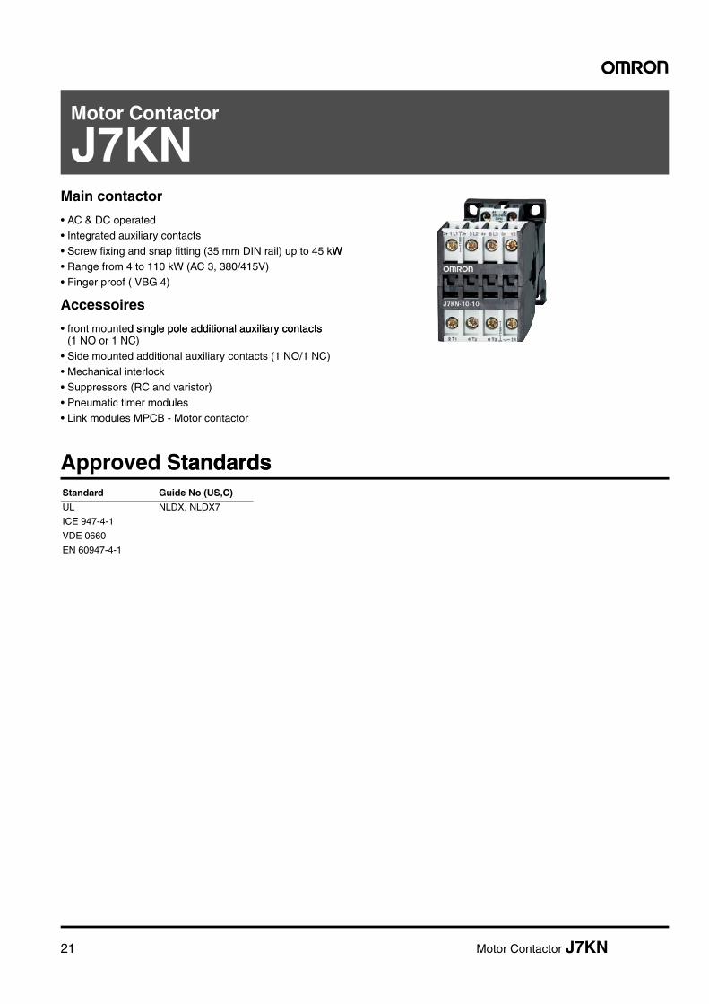
Motor Contactor
Main contactor
• AC & DC operated• Integrated auxiliary contacts• Screw fixing and snap fitting (35 mm DIN rail) up to 45 kWW
• Range from 4 to 110 kW (AC 3, 380/415V)• Finger proof ( VBG 4)
Accessoires
• front mounted single pole additional auxiliary contacts d single pole additional auxiliary contacts (1 NO or 1 NC)
• Side mounted additional auxiliary contacts (1 NO/1 NC)• Mechanical interlock• Suppressors (RC and varistor)
• Pneumatic timer modules• Link modules MPCB - Motor contactor
Approved StandardstandardsStandard Guide No (US,C)
UL NLDX, NLDX7
ICE 947-4-1
VDE 0660
EN 60947-4-1
22 Motor Contactor J7KN
Motor Contactor J7KN 23
Ordering Informationg Information
■ Model Number Legendber Legend1. Motor Contactors
1) Motor Contactor2) Rated Motor Current (AC3 400V)
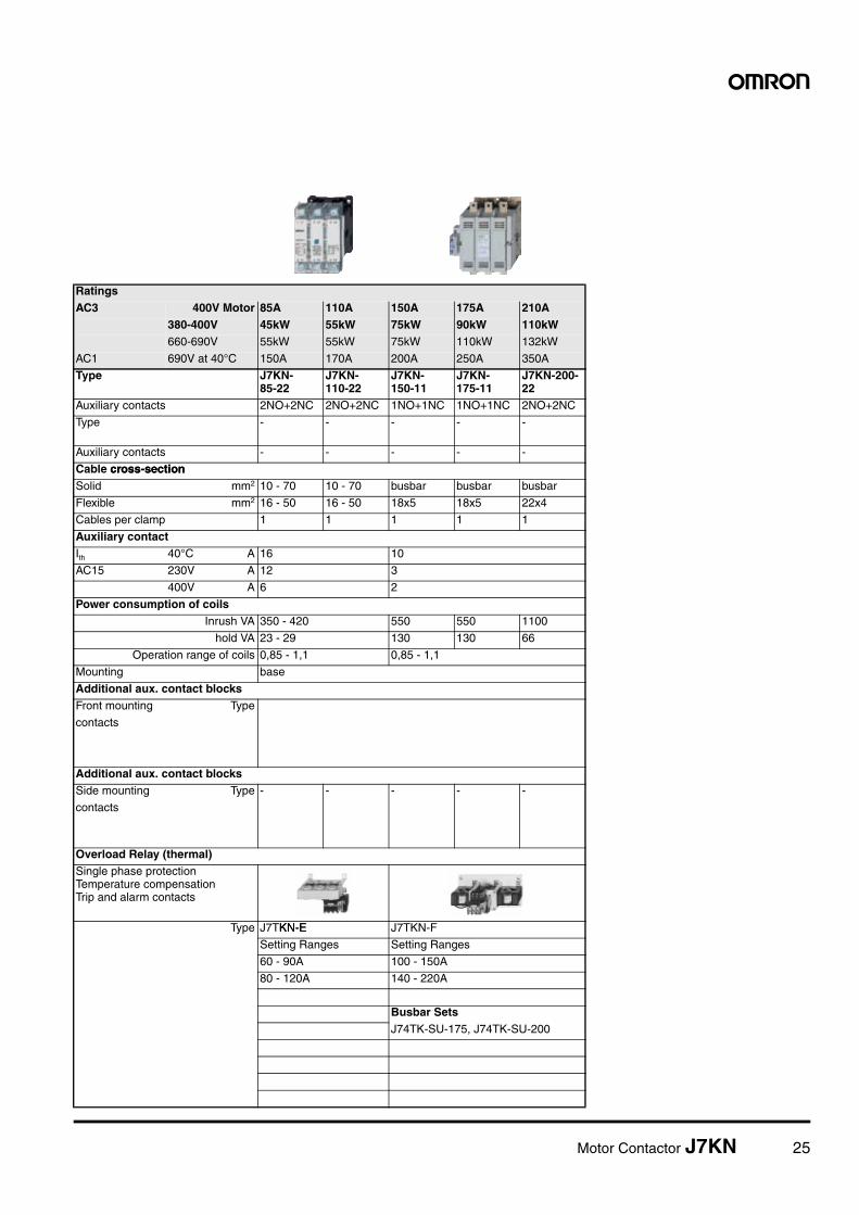
Overload Relay (thermal)Single phase protection Temperature compensation Trip and alarm contacts
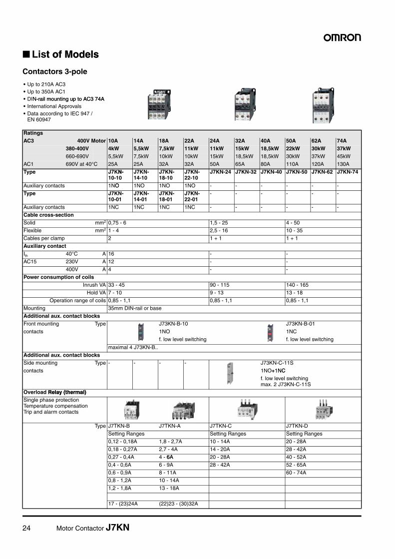
Type J7TKN-EKN-E J7TKN-F
Setting Ranges Setting Ranges
60 - 90A 100 - 150A
80 - 120A 140 - 220A
Busbar SetsJ74TK-SU-175, J74TK-SU-200
26 Motor Contactor J7KN
Contactors 3-poleAC Operated
Ratings Rated Current
Aux. Contacts Type Pack Weight
AC2, AC3 AC1 Built-in Additional
380V400V415VkWW
500V
kW
660V690V
kW
690V
A NO NC
seepage 28
Type
Coil Voltage*1
24 24V 50/60Hz110 110V 50Hz230 220-240V 50Hz
*1) Coil voltage range and other coil voltages see page 30
pcs. kg/pc.
4 5.5 5.5 25 1 - max. 4J73KN-B
J7KN-10-10#### 1 0.23
4 5.5 5.5 25 - 1 J7KN-10-01#### 1 0.23
5.5 7.5 7.5 25 1 - J7KN-14-10#### 1 0.23
5.5 7.5 7.5 25 - 1 J7KN-14-01#### 1 0.23
7.5 10 10 32 1 - J7KN-18-10#### 1 0.23
7.5 10 10 32 - 1 J7KN-18-01#### 1 0.23
11 10 10 32 1 - J7KN-22-10#### 1 0.23
11 10 10 32 - 1 J7KN-22-01#### 1 0.23
11 15 15 50 - - max. 4J73KN-B + 2 J73KN-C-11S
J7KN-24#### 1 0.48
15 18.5 18.5 65 - - J7KN-32#### 1 0.48
18.5 18.5 18.5 80 - - J7KN-40#### 1 0.48
22 30 30 110 - - max. 4J73KN-B + 2 J73KN-C11S
J7KN-50#### 1 0.85
30 37 37 120 - - J7KN-62#### 1 0.85
37 45 45 130 - - J7KN-74#### 1 0.85
Ratings Rated Current
Aux. Contacts Type Pack Weight
AC2, AC3 AC1 Built-in
380V415VkW
500V
kW
660V690V90VkW
690V
A NO NC
Coil Voltage*1
230 220-230V 50Hz400 380-400V 50Hz pcs. kg/pc.
45 55 55 150 2 2 J7KN-85-22#### 1 1.8
55 75 55 170 2 2 J7KN-110-22#### 1 1.9
75 75 75 200 1 1 J7KN-150-11#### 1 5
90 90 90 250 1 1 J7KN-175-11#### 1 5
110 132 132 350 2 2 J7KN-200-22#### 1 7.3
Motor Contactor J7KN 27
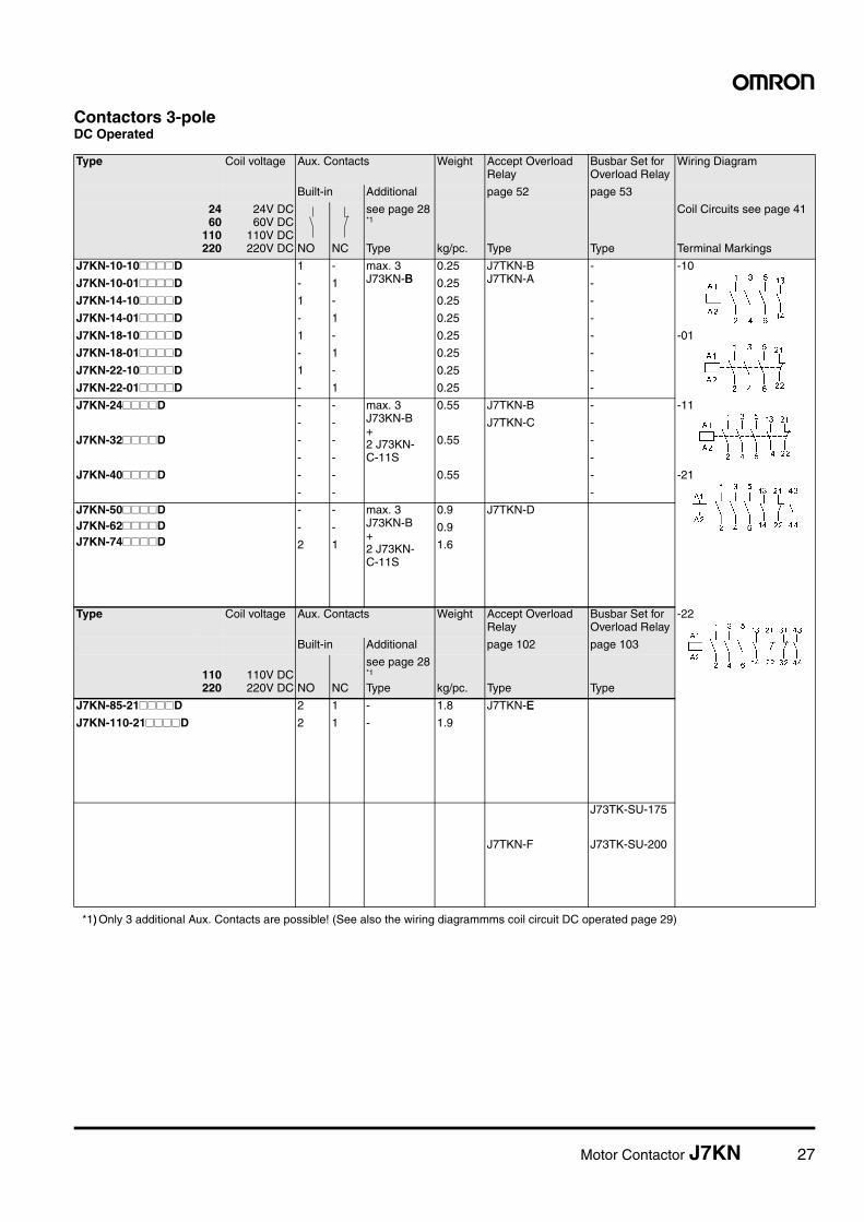
Contactors 3-poleDC Operated
Type Coil voltage Aux. Contacts Weight Accept Overload Relay
Busbar Set for Overload Relay
Wiring Diagram
Built-in Additional page 52 page 53
2460
110220
24V DC60V DC
110V DC220V DC NO NC
see page 28*1
Type
*1)) Only 3 additional Aux. Contacts are possible! (See also the wiring diagrammms coil circuit DC operated page 29)
kg/pc. Type Type
Coil Circuits see page 41
Terminal Markings
J7KN-10-10####D 1 - max. 3J73KN-BB
0.25 J7TKN-BJ7TKN-A
- -10
J7KN-10-01####D - 1 0.25 -
J7KN-14-10####D 1 - 0.25 -
J7KN-14-01####D - 1 0.25 -
J7KN-18-10####D 1 - 0.25 - -01
J7KN-18-01####D - 1 0.25 -
J7KN-22-10####D 1 - 0.25 -
J7KN-22-01####D - 1 0.25 -
J7KN-24####D - - max. 3J73KN-B+2 J73KN-C-11S
0.55 J7TKN-B - -11
- - J7TKN-C -
J7KN-32####D - - 0.55 -
- - -
J7KN-40####D - - 0.55 - -21
- - -
J7KN-50####DJ7KN-62####DJ7KN-74####D
- - max. 3J73KN-B+2 J73KN-C-11S
0.9 J7TKN-D
- - 0.9
2 1 1.6
Type Coil voltage Aux. Contacts Weight Accept Overload Relay
Busbar Set for Overload Relay
-22
Built-in Additional page 102 page 103
110220
110V DC220V DC NO NC
see page 28*1
Type kg/pc. Type Type
J7KN-85-21####D 2 1 - 1.8 J7TKN-EE
J7KN-110-21####D 2 1 - 1.9
J73TK-SU-175
J7TKN-F J73TK-SU-200
28 Motor Contactor J7KN
Contactors 4-poleAC Operated
Auxiliary Contact BlocksBlocks for contactors J7KN-10... to -74... type J73KN for low level switchinge J73KN for low level switching*1
Auxiliary Contact Blocks for contactors J7KN-10... to -74... type J73KN for low level switchingactors J7KN-10... to -74... type J73KN for low level switchingfor low level switching*1
Pneumatic Timer matic Timer for contactors J7KN-10... to -22...0... to -22...
Ratings Rated Current
Aux. Contacts Type Pack Weight
AC2, AC3
AC1 AC1Built-in Additional
seebelow
Type
380V400V415VkW
400V
kW
690V
A NO NC
Coil Voltage*1
24 24V 50/60Hz110 110V 50Hz230 220-240V 50Hz
*1) Coil voltage range and other coil voltages see page 30
pcs. kg/pc.
4 17.57.5 25 - - max. 4J73KN-B
J7KN-10-4#### 1 0.22
1. suitable according to DIN 19240 (test ratings 17V DC, 5mA) Technical data see page 45
Front mounting Rated Operational Current Contacts Type Pack Weight
AC15230V
AC15400V
AC1690V
EM LB
A A A NO NC pcs. kg/pc.
3 2 10 1 - - - J73KN-B-10 10 0.02
3 2 10 - 1 - - J73KN-B-01 10 0.02
Side mounting Rated Operational Currentonal Current Contacts Type Pack Weight
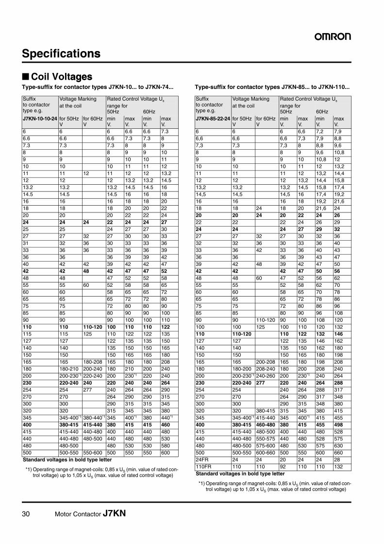
Type-suffix for contactor types J7KN-150... to J7KN-200...
Suffix Voltage Marking Rated Control Voltage Us
to contactor type e.g.
at the coil range for 50Hz 60Hz
J7KN-150-110 for 50HzV
for 60HzV
min V.
max V.
min V.
max V.
24 24 24 24 - -
48 48 48 48 - -
110 110 110 110 110 110 110
180 180 220 180 180 220 220
230 220-230 220 220 230 220 220
240 240 240 240 240 240 240
400 380-400 380 400 - -
440 440 - - 440 440
Standard voltages in bold type letter
32 Motor Contactor J7KN
■ Engineering data and characteristicscharacteristics
Approximate Values for three-phase Motorse Values for three-phase Motorshree-phase Motorstors
Motor Full Load CurrentsApproximate values of motor F.L.C. and minimum „slow blow“ respectively „gL“ short-circuit fusemate values of motor F.L.C. and minimum „slow blow“ respectively „gL“ short-circuit fuse
The motor F.L.C. be valid for standard internal and surface cooled three-pole motors with 1500 min-1. The fuses values be valid for the motor F.L.C. shown in the table and D.O.L.-start: starting current max. 6x motor F.L.C., starting time max. 5s; star-delta-start: starting current max. 2x motor F.L.C., starting time max. 15s. For motors with higher F.L.C., higher starting current and / or longer starting time, larger short-circuit fuses are required.
The maximum admissible value is dependent on the switchgear ble value is dependent on the switchgear respectively thermal overload relay.
Motor rating 220-230V Motor 240V Motor 380-400V Motor 415V Motor 500V Motor 660-690V Motor
Range according to BS for 415V Value of fusing at motor start
Data according to IEC 947-4-1, EN 60947-4-1, VDE 0660N 60947-4-1, VDE 0660Main Contacts Type J7KN-10 J7KN-14 J7KN-18 J7KN-22 J7KN-24 J7KN-32 J7KN-40 J7KN-50 J7KN-62 J7KN-74
Rated insulation voltage Ui*1 V AC 690 690 690 690 690 690 690 690 690 690
Making capacity Ieff at Ue = 690V AC A 200 200 200 200 400 500 500 700 900 900
Breaking capacity Ieff 400V AC A 180 180 200 200 380 400 400 600 800 800
J7KN-10 to J7KN-22 cos� = 0,65 500V AC A 150 150 180 180 300 370 370 500 700 700
J7KN-24 to J7KN-72 cos� = 0,35 690V AC A 100 100 150 150 260 340 340 400 500 500
1000V AC A - - - - - - - - -
Utilization category AC1 Switching of resistive load
Rated operational current Ie (=Ith) at 40°C, open A 25 25 32 32 50 65 80 110 120 130
For contactors with thermal overload relay the device with the smaller admissible backup fuse (contactor or thermal overload relay) determines the fuse size.
Cable cross-sectionsfor contactors without thermal overload relay
main connector solid or stranded mm² 0,75 - 6 1,5 - 25 4 - 50
flexible mm² 1 - 4 2,5 - 16 10 - 35
flexible with multicore cable end mm² 0,75 - 4 1,5 - 16 6 - 35
Short time current 10s-current A 96 120 144 176 184 240 296 360 504 592
Power loss per pole at Ie/AC3 400V W 0,21 0,35 0,5 0,75 0,7 1,3 2 2,2 3,9 5,5
Resistance to shock acc. to IEC 68-2-27
Shock time 20ms sine-wave NO g 10 10 10 10 8 8 8 8 8 8
NC g 6 6 6 6 - - - - - -
*1) Suitable at 690V for: earthed-neutral systems, overvoltage I to IV, pollution degree 3 (standard-industry): Uimp = 8kV. Data for other conditions on request.conditions on request.
*2) Metal halide lamps and sodium-vapour lamps (high- and low-pressure lamps)*3) High-pressure lamps*4) Blended lamps, containing a mercury high-pressure unit and a tungsten helix in a flourescent glass bulb (daylight lamps)*5) Current inrush approx. 16 x Ie*6) With reduced control voltage range 0,9 up to 1,0 x Us and with reduced rated current Ie/AC1 according to IAC1 according to Ie/AC3
Main Contacts Type J7KN-10 J7KN-14 J7KN-18 J7KN-22 J7KN-24 J7KN-32 J7KN-40 J7KN-50 J7KN-62 J7KN-74
Motor Contactor J7KN 37
Main Contacts Type J7KN-85 J7KN-110 J7KN-150 J7KN-175 J7KN-200
Rated insulation voltage Ui *1 V AC 750 750 690 690 690
Making capacity Ieff at Ue = 690V AC A 1100 1200 1500 1800 1700
Breaking capacity Ieff 400V AC A 950 1100 1200 1400 1600
J7KN-10 to J7KN-22 cos� = 0,65 500V AC A 850 1000 1200 1400 1600
J7KN-24 to J7KN-72 cos� = 0,35 690V AC A 600 600 700 800 1200
1000V AC A - - - - -
Utilization category AC1 Switching of resistive load
Rated operational current Ie (=Ith) at 40°C, open A 150 170 200 250 350
Rated operational current Ie 400V A 38 50 65 80 90
Rated operational power dependent on inrush n
220-230V kVA 15 20 25 30 34
240V kVA 15,5 20,5 27 33 37
380-400V kVA 26 34 45 55 60
For different inrush-factors xuse the following formula:Px=Pn*(n/x)
415-440V kVA 29 38 46 57 63
500V kVA 33 43 55 69 75
660-690V 45 60 56 69 100
Utilization category AC6bSwitching of three-phase capacitor banks
Maximum inrush current (peak val-ue) as multiple k of the capacitor rated current
k 20 20 20 20 15
Rated operational current Ie 500V A 87 100 120 155 195
Rated operational power(sinjÆ1)
220-230V kVAr 33 38 45 60 75
240V kVAr 36 42 52 62 78
380-400V kVAr 57 65 80 100 130
For different multiples x use the following formula:Px=Pk*(k/x)
415-440V kVAr 60 70 95 110 135
500V kVAr 70 80 100 130 170
660-690V kVAr 70 80 100 130 170
Switching of detuned capacitors
Rated operational current Ie 690V A 98 105 115 140 200
Rated operational power 220-230V kVAr 35 40 43 53 76
240V kVAr 39 43 45 55 80
380-400V kVAr 68 75 75 90 130
415-440V kVAr 71 77 80 100 140
500V kVAr 85 90 95 120 170
660-690V kVAr 110 120 125 150 200
Utilization category DC1Switching of resistive load
Time constant L/R £1ms
Rated operational current Ie 1 pole24V A 150 170 - - -
60V A 150 170 - - -
110V A 20 25 - - -
220V A 2 2,5 - - -
3 poles in series 24V A 150 170 200 250 350
60V A 150 170 200 250 350
110V A 150 170 150 170 250
220V A 100 160 80 100 150
Main Contacts Type J7KN-85 J7KN-110 J7KN-150 J7KN-175 J7KN-200
Motor Contactor J7KN 39
Utilization category DC3 and DC5Switching of shunt motors and series motors
Time constant L/R £15ms
Rated operational current Ie 1 pole24V A 150 170 - - -
60V A 85 110 - - -
110V A 2 2,5 - - -
220V A 0,5 0,5 - - -
3 poles in series 24V A 150 170 - - -
60V A 100 110 - - -
110V A 100 110 - - -
220V A 7 8 - - -
Maximum ambient temperature
Operation open °C -40 to +60 (+90)*6 -25 to +55 (+70)*7
enclosed °C -40 to +40 -25 to +40
with thermal overload relay open °C -25 to +60 -25 to +55
enclosed °C -25 to +40 -25 to +40
Storage °C -50 to +90 -55 to +80
Short circuit protectionfor contactors without thermal overload relay
Coordination-type "1" according to IEC 947-4-1Contact welding without hazard of persons
max. fuse size gL (gG) A 250 250 250 315 400
Coordination-type “2” according to IEC 947-4-1Light contact welding accepted
max. fuse size gL (gG) A 160 200 200 250 315
Contact welding not accepted
max. fuse size gL (gG) A 100 125 160 200 250
For contactors with thermal overload relay the device with the smaller admissible backup fuse (contactor or thermal overload relay) determines the fuse size.
Cable cross-sectionsfor contactors without thermal overload relay
main connector solid or stranded mm² 10 - 70*8 10 - 70*8 95 120 185
flexible mm² 6 - 50*8 16 - 50*8 screw screw screw
flexible with multicore cable end mm² 10 - 35 10 - 35 M8 M8 M8
Cables per clamp
solid or stranded mm²
flexible mm²
Cables per clamp
main connector solid AWG 10 10
flexible AWG 6 - 0 6 - 0
Cables per clamp 1 1
solid AWG
flexible AWG
Cables per clamp
Frequency of operations zContactors without thermal overload relay
without load 1/h 3000 3000 1200 1200 1200
AC3, Ie 1/h 300 300 - - -
AC4, Ie 1/h 120 120 - - -
DC3, Ie 1/h 300 300 - - -
Mechanical life
AC operated S x 106 5 5 10 10 8
DC operated S x 106 5 5 10 10 8
Short time current 10s-current A 680 880 1200 1400 1800
Power loss per pole at Ie/AC3 400V W 4,3 6,0 8 11 8
Resistance to shock acc. to IEC 68-2-27
Shock time 20ms sine-wave NO g 7 7 - - -
NC g 5 5 - - -
*1) Suitable at 690V for: earthed-neutral systems, overvoltage I to IV, pollution degree 3 (standard-industry): Uimp = 8kV. Data for other conditions on request.
*2) Metal halide lamps and sodium-vapour lamps (high- and low-pressure lamps)*3) High-pressure lamps*4) Blended lamps, containing a mercury high-pressure unit and a tungsten helix in a flourescent glass bulb
(daylight lamps)*5) Current inrush approx. 16 x Ie*6) With reduced control voltage range 0,9 up to 1,0 x Us and with reduced rated current Ie/AC1 according to Ie/AC3*7) With reduced control voltage range 1,0 x Us and with reduced rated current Ie/AC1 according to Ie/AC3*8) Maximum cable cross-section with prepared conductor
Main Contacts Type J7KN-85 J7KN-110 J7KN-150 J7KN-175 J7KN-200
40 Motor Contactor J7KN
Contactors
Data according to IEC 947-4-1, EN 60947-4-1, VDE 0660ding to IEC 947-4-1, EN 60947-4-1, VDE 0660VDE 0660Auxiliary Contacts Type J7KN-10 J7KN-14 J7KN-18 J7KN-22 J7KN-24 J7KN-32 J7KN-40 J7KN-50 J7KN-62 J7KN-74
Rated insulation voltage Ui*1
*1) Suitable for: earthed-neutral systems, overvoltage category I to IV, pollution degree 3 (standard-industry): Uimp = 8kV. Data for other con-ditions on request
V~ 690 690 690 690 - - - - - -
Thermal rated current Ith to 690V
Ambient temperature 40°C A 16 16 16 16 - - - - - -
60°C A 12 12 12 12 - - - - - -
Utilization category AC15
Rated operational current Ie 220-240V A 12 12 12 12 - - - - - -
380-415V A 4 4 4 4 - - - - - -
440V A 4 4 4 4 - - - - - -
500V A 3 3 3 3 - - - - - -
660-690V A 1 1 1 1 - - - - - -
Utilization category DC13
Rated operational current Ie 60V A 8 8 8 8 - - - - - -
110V A 1 1 1 1 - - - - - -
220V A 0,1 0,1 0,1 0,1 - - - - - -
Short circuit protection
short-circuit current 1kA, contact welding not accepted
max. fuse size gL (gG) A 25 25 25 25 - - - - - -
For contactors with thermal overload relay the device with the smaller admissible control fuse (contactor or thermal overload relay) determines the fuse.
Control CircuitPower consumption of coils
AC operated inrush VA 33-45 90-115 140-165
sealed VA 7-10 9-13 13-18
W 2,6-3 2,7-4 5,4-7
DC operated inrush W 75 140 200
sealed W 2 2 6
Operation range of coils
in multiples of control voltage Us AC operated 0,85-1,1 0,85-1,1 0,85-1,1
DC operated 0,8-1,1 0,8-1,1 0,8-1,1
Switching time at control voltage Us ±10%*2,*3
*2) Total breaking time = release time + arc duration*3) Values for delay of the release time of the making contact and the make time of the break contact will be increased, if magnet coils are
protected against voltage peaks (varistor, RC-unit, diode-unit)
AC operated make time ms 8-16 10-25 12-28
release time ms 5-13 8-15 8-15
arc duration ms 10-15 10-15 10-15
DC operated make time ms 8-12 10-20 12-23
release time ms 8-13 10-15 10-18
arc duration ms 10-15 10-15 10-15
Cable cross-section
Auxiliary connector solid mm² 0,75-6 - -
flexible mm² 1-4 - -
flexible with multicore cable end mm² 0,75-4 - -
Magnet coil solid mm² 0,75-2,5 0,75-2,5 0,75-2,5
flexible mm² 0,5-2,5 0,5-2,5 0,5-2,5
flexible with multicore cable end mm² 0,5-1,5 0,5-1,5 0,5-1,5
Clamps per pole 2 2 2
Auxiliary connector solid AWG 18 - 10- - -
flexible AWG 18 - 10 - -
Magnet coil solid AWG 14 - 12 14 - 12 14 - 12
flexible AWG 18 - 12 18 - 12 18 - 12
Clamps per pole 2 2 2
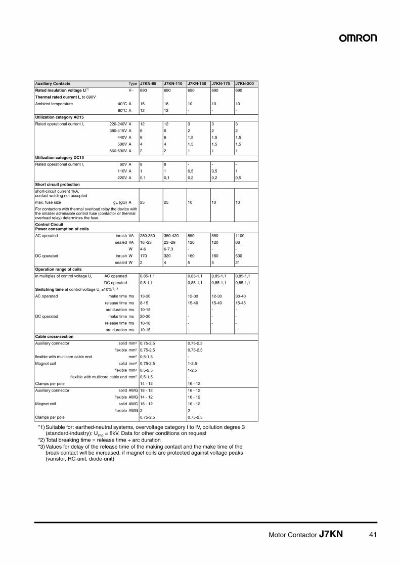
Motor Contactor J7KN 41
Auxiliary Contacts Type J7KN-85 J7KN-110 J7KN-150 J7KN-175 J7KN-200
Rated insulation voltage Ui*1
*1) Suitable for: earthed-neutral systems, overvoltage category I to IV, pollution degree 3 (standard-industry): Uimp = 8kV. Data for other conditions on request
V~ 690 690 690 690 690
Thermal rated current Ith to 690V
Ambient temperature 40°C A 16 16 10 10 10
60°C A 12 12 - - -
Utilization category AC15
Rated operational current Ie 220-240V A 12 12 3 3 3
380-415V A 6 6 2 2 2
440V A 6 6 1,5 1,5 1,5
500V A 4 4 1,5 1,5 1,5
660-690V A 2 2 1 1 1
Utilization category DC13
Rated operational current Ie 60V A 8 8 - - -
110V A 1 1 0,5 0,5 1
220V A 0,1 0,1 0,2 0,2 0,5
Short circuit protection
short-circuit current 1kA, contact welding not accepted
max. fuse size gL (gG) A 25 25 10 10 10
For contactors with thermal overload relay the device with the smaller admissible control fuse (contactor or thermal overload relay) determines the fuse.
Control CircuitPower consumption of coils
AC operated inrush VA 280-350 350-420 550 550 1100
sealed VA 16 -23 23 -29 120 120 66
W 4-6 6-7,3 - - -
DC operated inrush W 170 320 160 160 530
sealed W 2 4 5 5 21
Operation range of coils
in multiples of control voltage Us AC operated 0,85-1,1 0,85-1,1 0,85-1,1 0,85-1,1
DC operated 0,8-1,1 0,85-1,1 0,85-1,1 0,85-1,1
Switching time at control voltage Us ±10%*2,*3
*2) Total breaking time = release time + arc duration*3) Values for delay of the release time of the making contact and the make time of the
break contact will be increased, if magnet coils are protected against voltage peaks (varistor, RC-unit, diode-unit)
AC operated make time ms 13-30 12-30 12-30 30-40
release time ms 8-15 15-40 15-40 15-45
arc duration ms 10-15 - -
DC operated make time ms 20-30 - - -
release time ms 10-18 - - -
arc duration ms 10-15 - - -
Cable cross-section
Auxiliary connector solid mm² 0,75-2,5 0,75-2,5
flexible mm² 0,75-2,5 0,75-2,5
flexible with multicore cable end mm² 0,5-1,5 -
Magnet coil solid mm² 0,75-2,5 1-2,5
flexible mm² 0,5-2,5 1-2,5
flexible with multicore cable end mm² 0,5-1,5 -
Clamps per pole 14 - 12 16 - 12
Auxiliary connector solid AWG 18 - 12 16 - 12
flexible AWG 14 - 12 16 - 12
Magnet coil solid AWG 18 - 12 16 - 12
flexible AWG 2 2
Clamps per pole 0,75-2,5 0,75-2,5
42 Motor Contactor J7KN
Contactors for North AmericaNorth Americaca
Data according to UL5088Main Contacts (cULus) Type J7KN-10 J7KN-14 J7KN-18 J7KN-22 J7KN-24 J7KN-32 J7KN-40 J7KN-50 J7KN-62 J7KN-74
Rated operational current "General Use"
A 25 25 30 30 50 65 80 110 120 130
Rated operational power 110-120V hp 1½ 2 2 3 5 5 7½ 10 10 10
of three-phase motors 200V hp 3 3 5 5 7½ 10 10 15 20 25
at 60Hz (3ph) 220-240V hp 3 3 7½ 7½ 10 10 15 20 25 30
277V hp 3 5 7½ 7½ 7½ 10 15 20 25 30
380-415V hp 5 5 10 10 10 15 20 25 30 40
440-480V hp 5 7½ 10 15 15 20 25 30 40 50
550-600V hp 7½ 10 15 20 20 25 30 40 50 50
Rated operational power 110-120V hp ½ ¾ 1 1½ 1½ 2 3 3 5 7½
of AC motors 200V hp 1 1,5 2 3 3 5 7½ 7½ 10 15
at 60Hz (1ph) 220-240V hp 1½ 2 3 3 5 5 7½ 10 15 15
277V hp 2 3 3 5 5 7½ 10 10 15 15
380-415V hp 3 3 5 5 5 7½ 10 15 20 20
440-480V hp 3 5 5 7½ 7½ 10 15 20 25 25
550-600V hp 3 5 7½ 10 10 15 20 25 30 30
Rated operational power of 110-120V hp - - - - 2 3 - 3 5 -
three-phase motors at 60Hz (3ph) 200V hp - - - - 3 5 - 7½ 10 -
Main Contacts (cULus) Type J7KN-85 J7KN-110 J7KN-150 J7KN-175 J7KN-200
Rated operational current "General Use"
A 125 125 - - -
Rated operational power 110-120V hp 15 - - - -
of three-phase motors 200V hp - 30 - - -
at 60Hz (3ph) 220-240V hp 35 40 - - -
277V hp - - - - -
380-415V hp - - - - -
440-480V hp 65 75 - - -
550-600V hp 85 100 - - -
Rated operational power 110-120V hp 8 10 - - -
of AC motors 200V hp - 20 - - -
at 60Hz (1ph) 220-240V hp 20 20 - - -
277V hp - - - - -
380-415V hp - - - - -
440-480V hp - 50 - - -
550-600V hp - 60 - - -
Rated operational power of 110-120V hp - - - - -
three-phase motors at 60Hz (3ph) 200V hp - - - - -
for elevators 220-240V hp - - - - -
Demands according to ANSI A17.5
(500.000 operations) 440-480V hp - - - - -
550-600V hp - - - - -
Rated operationalcurrent 600V A - 62 - - -
Fuses A - 300 - - -
Suitable for use on a capability
of delivering not more than rms A 10000 10000 - - -
V 600 600 - - -
Auxiliary Contacts (cULus) A600 A600 - - -
Motor Contactor J7KN 43
Contactors
Data according to IEC 947-4-1, EN 60947-4-1, VDE 0660N 60947-4-1, VDE 0660Contact Life
For selection of the suitable contactor-type according to supply volt-age, power rating and application (utilization category AC1, AC3 or AC4) use contact life characteristic diagram.
For the most common supply voltages four scales of power ratings Pn are provided for each utilization category.
Select contactor-type according to utilization category AC3 (breaking current Ia = Ie) using the motor rating scales to the right, according to utilization category AC4 (breaking current Ia = 6 x Ie) using the motor rating scales to the left.*1
Select contactor-type according to utilization category AC1 (breaking current Ia = Ie/AC1) using the breaking current scale.*1
For contactors frequently used under AC3/AC4-mixed service condi-tions calculate contact life with the formula:
1. Pay attention to the approved rated values of the selectedcontactor according to the national approvals
M = Contact life (switching cycles) for AC3/AC4-mixed operations
AC3 = Contact life (switching cycles) for AC3 operations (normal switching conditions). Breaking current Ia = rated motor current In.
AC4 = Contact life (switching cycles) for AC4 operations (inch-ing).
Breaking current Ia= multiples of rated motor current In.
%AC4 = Percents of AC4-operations related to the total cycles.
A
Motor RatingPn/AC4
Motor RatingPn/AC3
Breaking CurrentIa (=Ie/AC1)
J7KN-74
J7KN-24
J7KN-32J7KN-40
J7KN-50J7KN-62
J7KN-22J7KN-18J7KN-14J7KN-12J7KN-10J7KN-09
millions of operations
44 Motor Contactor J7KN
A
Motor RatingPn/AC4
Motor RatingPn/AC3
Breaking CurrentIa (=Ie/AC1)
J7KN-200
J7KN-150J7KN-175
J7KN-110
J7KN-85
millions of operations
Motor Contactor J7KN 45
Contactors
Utilization Categorieson CategoriesFor easier choice of devices and in order to make the comparison of different products simplier are utilization categories for contactors and motor-starters according to IEC 947-4-1 and VDE 0660 Part 102,for EC 947-4-1 and VDE 0660 Part 102,for
control circuit devices and switching elements according to IEC 947-5-1 and VDE 0660 Part 200 determind. The table offers different utiliza-tion categories, typical applications and assorted test conditions.
Ue Rated operational voltage, U Voltage before make, Ur Recovery voltage, Ie Rated operational current, I Current make, Ic Current broken
1) Test with incandescent lamps2) Test conditions according to standard
Type of current
Cate-gory
Typical applications Rated operational current
Test conditions for the number ofon-load operating cycles
Test conditions for making and breaking capacities
Auxiliary Contacts Type J73KN-B J73KN-C J73KN-B-TP...
Rated insulation voltage Ui*1
*1) Suitable for: earthed-neutral systems, overvoltage category I to IV, pol-lution degree 3 (standard-industry): Uimp = 8kV. Data for other condi-8kV. Data for other condi-tions on request
V~ 690 690 690
Thermal rated current Ith to 690V
Ambient temperature 40°C A 10 10 10
60°C A 6 6 -
Frequency of operations z 1/h 3000 3000 1200
Mechanical life S x 106
10 10 1
Power loss per pole at Ie/AC1 W 0,5 0,5 -
Utilization category AC15
Rated operational current Ie 220-240V A 3 3 4
380-400V A 2 2 3
440V A 1,6 1,6 2
500V A 1,2 1,2 2
660-690V A 0,6 0,6 2
Utilization category DC13
Rated operational current Ie 60V A 2 2 2,5
110V A 0,4 0,4 1,5
220V A 0,1 0,1 0,2
Short circuit protection
short-circuit current 1kA, contact welding not accepted max. fuse size
gL (gG) A 20 20 10
For contactors with thermal overload relay or auxiliary con-tacts the device with the smaller admissible control fuse (contactor or thermal overload relay) determines the fuse size.
Cable cross-sections
solid or stranded mm² 0,75-2,5 0,75-2,5 1-2,5
flexible mm² 0,75-2,5 0,75-2,5 0,75-2,5
flexible with multicore cable end mm² 0,5-1,5 0,5-1,5 0,75-2,5
Cables per clamp 2 2 2
Auxiliary Contacts Type J73KN-B J73KN-C J73KN-B-TP...