16
Apr. 3, 2000 Systems Architecture I 1 Systems Architecture I (CS 281-001) Lecture 3: Review of Digital Circuits and Logic Design Jeremy R. Johnson Mon. Apr. 3, 2000
| Date post: | 31-Dec-2015 |
| Category: |
Documents |
| Upload: | iris-booker |
| View: | 216 times |
| Download: | 0 times |

Apr. 3, 2000 Systems Architecture I 1
Systems Architecture I (CS 281-001)
Lecture 3: Review of Digital Circuits and Logic Design
Jeremy R. Johnson
Mon. Apr. 3, 2000

Apr. 3, 2000 Systems Architecture I 2
Introduction
• Objective: To understand how the simple model computer from the previous lecture could be implemented using logic gates.
• Review of Boolean functions and expressions• Review of logic gates• Decoders, Encoders, and Multiplexors
References: Dewdney, The New Turing Omnibus (Chapter 3, 13, and 28) and Sec. B1-B3 of the text.

Apr. 3, 2000 Systems Architecture I 3
Boolean Functions
• A boolean variable has two possible values (true/false) (1/0).
• A boolean function has a number of boolean input variables and has a boolean valued output.
• A boolean function can be described using a truth table
• There are 22n boolean
function of n variables.
s x0 x1 f
0 0 0 0
0 0 1 0
0 1 0 1
0 1 1 1
1 0 0 0
1 0 1 1
1 1 0 0
1 1 1 1
f
x0
x1
s
Multiplexor function

Apr. 3, 2000 Systems Architecture I 4
Boolean Expressions
• An expression built up from variables, and, or, and not.
x y x y
0 0 0
0 1 0
1 0 0
1 1 1
x y x + y
0 0 0
0 1 1
1 0 1
1 1 1
x x
0 1
1 0
and or not

Apr. 3, 2000 Systems Architecture I 5
Boolean Expressions
• A boolean expression is a boolean function.
• Any boolean function can be written as a boolean expression
– Disjunctive normal form (sums of products)– For each row in the truth table where the output is
true, write a product such that the corresponding input is the only input combination that is true
– Not unique
• E.G. (multiplexor function)
s x0 x1 + s x0 x1 + s x0 x1 + s x0 x1
s x0 x1 f
0 0 0 0
0 0 1 0
0 1 0 1
0 1 1 1
1 0 0 0
1 0 1 1
1 1 0 0
1 1 1 1

Apr. 3, 2000 Systems Architecture I 6
Boolean Logic
• Boolean expressions can be simplified using rules of boolean logic
– Identity law: A + 0 = A and A 1 = A.– Zero and One laws: A + 1 = 1 and A 0 = 0.– Inverse laws: A + A = 1 and A A = 0.– Commutative laws: A + B = B + A and A B = B A.– Associative laws: A + (B + C) = (A + B) + C and A (B C) = (A B) C.– Distributive laws: A (B + C) = (A B) + (A C) and
A + (B C) = (A + B) (A + C)– Demorgan’s laws: A + B = A B and A B = A + B
• The reason for simplifying is to obtain shorter expressions, which we will see leads to simpler logic circuits.

Apr. 3, 2000 Systems Architecture I 7
Simplification of Boolean Expressions
• Simplifying multiplexor expression using Boolean algebra
s x0 x1 + s x0 x1 + s x0 x1 + s x0 x1
= s x0 x1 + s x0 x1 + s x1 x0 + s x1 x0 (commutative law)
= s x0 (x1 + x1) + s x1 (x0 + x0) (distributive law)
= s x0 1 + s x1 1 (inverse law)
= s x0 + s x1 (identity law)
• Verify that the boolean function corresponding to this expression as the same truth table as the original function.

Apr. 3, 2000 Systems Architecture I 8
Logic Circuits
• A single line labeled x is a logic circuit. One end is the input and the other is the output. If A and B are logic circuits so are:
• and gate
• or gate
• inverter (not)
AB
A
AB
Apr. 3, 2000 Systems Architecture I 9
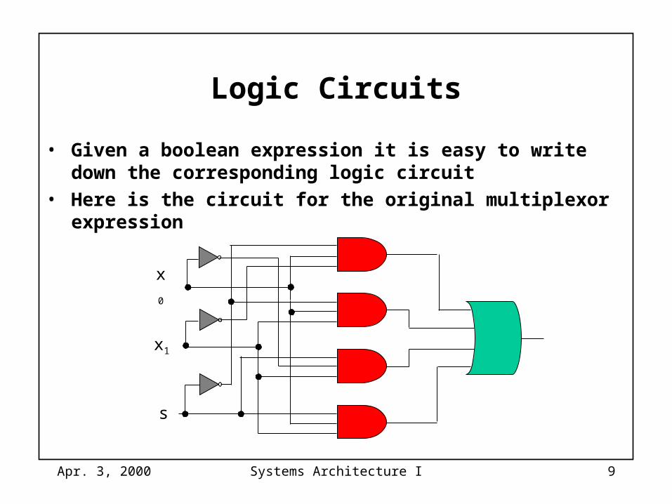
Logic Circuits
• Given a boolean expression it is easy to write down the corresponding logic circuit
• Here is the circuit for the original multiplexor expression
x0
x1
s

Apr. 3, 2000 Systems Architecture I 10
Logic Circuits
• Here is the circuit for the simplified multiplexor expression
x0
x1
s

Apr. 3, 2000 Systems Architecture I 11
Nand Gates
• A nand gate is an inverted and gate
• All boolean functions can be implemented using nand gates (and and not can be implemented using nand)
x y x | y
0 0 1
0 1 1
1 0 1
1 1 0
nand
=xxx

Apr. 3, 2000 Systems Architecture I 12
Decoder
• A decoder is a logic circuit that has n inputs (think of this as a binary number) and 2n outputs. The output corresponding to the binary input is set to 1 and all other outputs are set to 0.
d0
d1
d2
d3
b0
b1
Apr. 3, 2000 Systems Architecture I 13
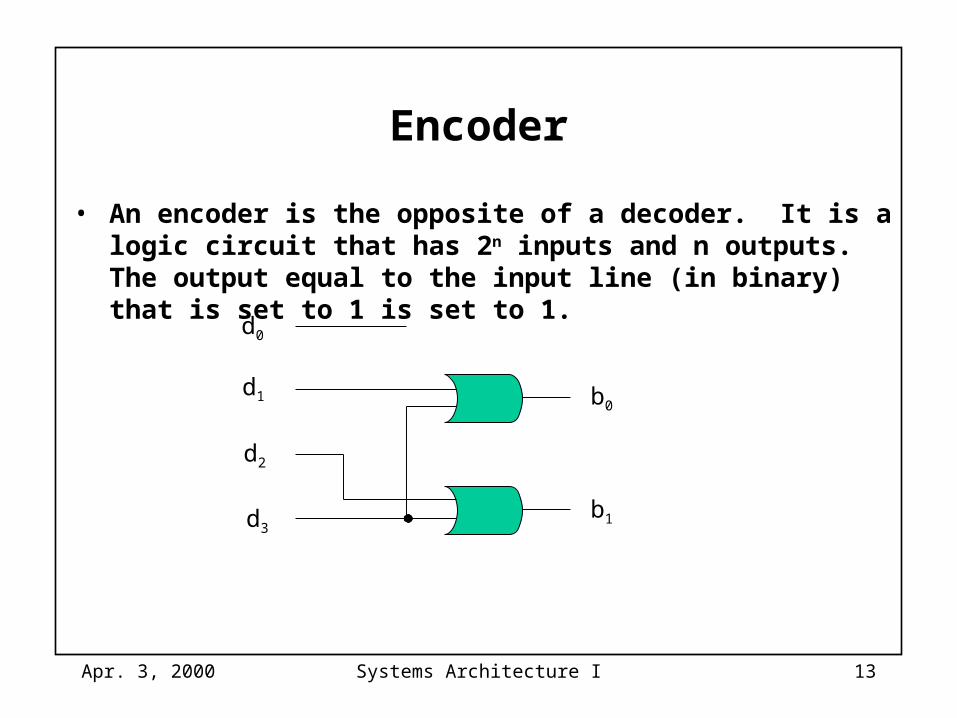
Encoder
• An encoder is the opposite of a decoder. It is a logic circuit that has 2n inputs and n outputs. The output equal to the input line (in binary) that is set to 1 is set to 1.
d0
d1
d2
d3
b0
b1

Apr. 3, 2000 Systems Architecture I 14
Multiplexer
• A multiplexor is a switch which routes n inputs to one output. The input is selected using a decoder.
d0
d1
d2
d3
s0s1

Apr. 3, 2000 Systems Architecture I 15
Implementing Logic Gates with Transitors
output
gate
+V
ground
A Transistor NOT Gate
A NAND B
A
+V
ground
A Transistor NAND Gate
B
Apr. 3, 2000 Systems Architecture I 16
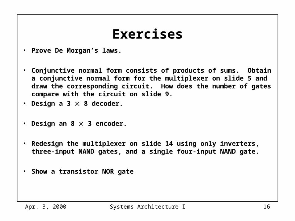
Exercises• Prove De Morgan’s laws.
• Conjunctive normal form consists of products of sums. Obtain a conjunctive normal form for the multiplexer on slide 5 and draw the corresponding circuit. How does the number of gates compare with the circuit on slide 9.
• Design a 3 8 decoder.
• Design an 8 3 encoder.
• Redesign the multiplexer on slide 14 using only inverters, three-input NAND gates, and a single four-input NAND gate.
• Show a transistor NOR gate


![arXiv:1907.10830v4 [cs.CV] 8 Apr 2020arXiv:1907.10830v4 [cs.CV] 8 Apr 2020 Published as a conference paper at ICLR 2020 Figure 1: The model architecture of U-GAT-IT. The detailed notations](https://static.documents.pub/doc/80x56/5f2547efc82d4979fe5d25c4/arxiv190710830v4-cscv-8-apr-2020-arxiv190710830v4-cscv-8-apr-2020-published.jpg)


