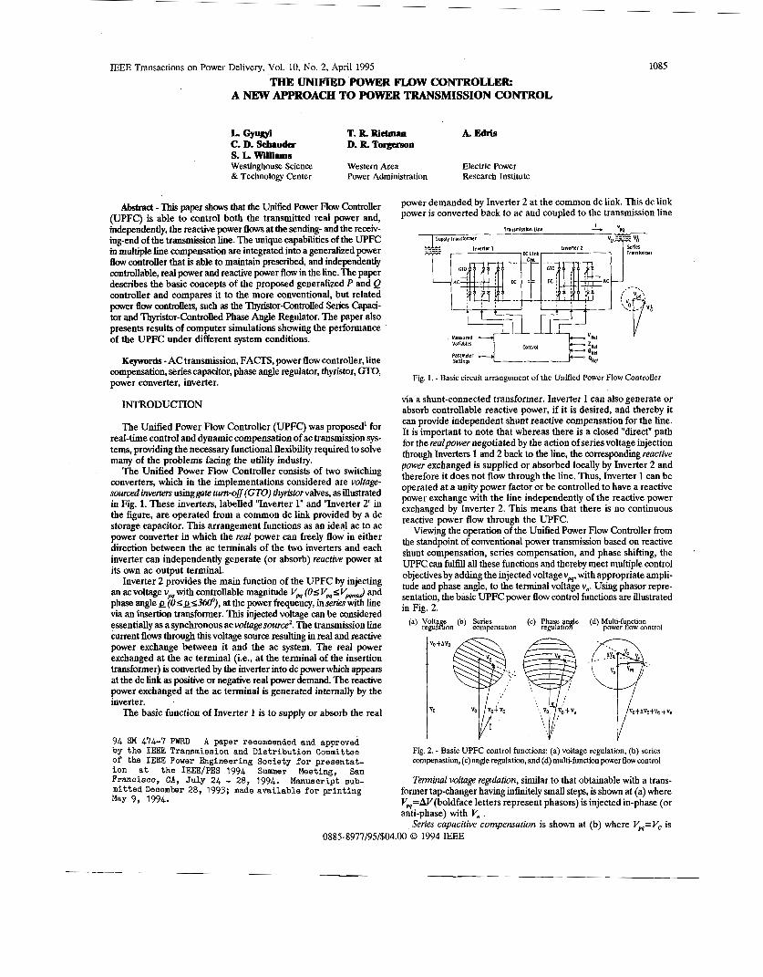
IEEE Transactions on Power Delivery, Vol. 10, No. 2, April 1995 THE UNIFIED POWFBFLOW CONTROLLER: A NEW APPROACH TO POWER TRANSMISSION CONTROL L. Gyqyi T. R Rietman A. Edris C. D. Schauda s. L. willirms Westinghouse Science Western Area Electric Power ti Technology Center Power Administration Research Institute D. R To~o Abstract - ll& paper shm that the Unified Power Flow Controller (UPFC) is able to control both the transmitted real power and, independently, the reactive power flows at the sending- and the receb- ing-end of the transmission line. The unique capabilities of the UPFC in multiple line Compensation are integrated into a generalized power flow controller that is able to maintain prescribed, and independently controllable, real power and reactive p er flow in the line. The paper describes the basic concepts of the proposed generalized P and Q controller and compares it to the more conventional, but related power flow controle~ such as the l%y&br-Controlled Series Capaci- tor and Thyristor-Controlled Phase Angle Regulator. The paper also presents results of computer simulations showing the performance of the UPFC under different system conditions. Keywords - AC transmission,FACTS, power flow controller, line compensation, seriescapacitor, phase angle regulator, thyristor, GTO, power converter, inverter. INTRODUCI'ION The Unified Power Flow Controller (UPFC) was proposed' for real-time control and dynamic compensationof ac transmission sys- tems, providing the necessary functional flexibility required to solve many of the problems facing the utility industy. The Unified Power Flow Controller consists of two switching converters, which in the implementations considered are voltage- sourced inverters usinggate tzun-off (GTO) thyritorvalves, as illustrated in Fig. 1. These inverters, labelled "Inverter 1" and "Inverter 2" in the figure, are operated from a common dc link provided by a dc storage capacitor. This arrangement functions as an ideal acto ac power converter in which the real power can freely flow in either direction between the ac terminals of the two inverters and each inverter can independently generate (or absorb) reactive power at its own ac output terminal. Inverter 2 provides the main function of the UPFC by injecting an acvoltage vw with controllable magnitude Vm (OsV,sV& and phase angle Q (OSQS~~), at the power frequency, inserh with line via an insertion transformer. This injected voltage can be considered essentially as a synchronous ac voltage source'. The transmission line current flows through this voltage source resulting in real and reactive power exchange between it and the ac system. The real power exchanged at the ac terminal (i.e., at the terminal of the insertion transformer) is converted by the inverter into dc power which appears at the dc link as positive or negative real power demand. The reactive power exchanged at the ac terminal is generated internally by the inverter. The basic function of Inverter 1 is to supply or absorb the real 94 SM 474-7 PWRD A paper recommended and approved by the IEEE Transmission and Distribution Committee of the IEEE Power Engineering Society for presentat- ion et the IEEE/PES 1994 Summer Meeting, San Francisco, CA, July 24 - 28, 1994. Manuscript sub- mittedDecember 28, 1993; made available for printing May 9, 1994. 1085 power demanded by Inverter 2 at the common dc link. This dc link power is converted back to ac and coupled to the transmission line I " lnnrmirrlon Une - w su@y Transformer Inverter 1 Inwrler 2 ___-- L Measured Variables Tu< cnntml 'Re1 ZRef 0IW 'Ref Panmeter Satlngr Fig. 1. - Basic circuit arrangement of the Unified Power Flow Controller via a shunt-connected transformer. Inverter 1 can also generate or absorb controllable reactive power, if it is desired, aild thereby it can provide independent shunt reactive compensation for the line. It is important to note that whereas there is a closed "direct" path for the realpower negotiated by the action of seriesvoltage injection through Inverters 1 and 2 back to the line, the corresponding reactive power exchanged is supplied or absorbed locally by Inverter 2 and therefore it does not flow through the line. Thus, Inverter 1 can be operated at a unity power factor or be controlled to have a reactive power exchange with the line independently of the reactive power exchanged by Inverter 2. This means that there is no continuous reactive power flow through the UPFC. Viewing the operation of the Unified Power Flow Controller from the standpoint of conventional power transmission based on reactive shunt compensation, series compensation, and phase shifting, the UPFC can fulfill all these functions and thereby meet multiple control objectives by adding the injected voltage vp4, with appropriate ampli- tude and phase angle, to the terminal voltage v,. Using phasor repre- sentation, the basic UPFC power flow control functions are illustrated in Fig. 2. (c) Phase angle (d) Multi-function power flow control (a) Volta e @) Series regulAion compensation regulation Fig. 2. - Basic UPFC control functions: (a) voltage regulation, @) series compenastion, (c) angle regulation, and (d) multi-function power flow control Terminal voltage regulation, similar to that obtainable with a trans- former tap-changer having infinitely small steps, is shown at (a) where Vm=AV(boldface letters represent phasors) is injected in-phase (or anti-phase) with V, . Series capacitive compensation is shown at (b) where Vm=Vc is 0885-8977/95/$04.00 0 1994 IEEE
Transcript
IEEE Transactions on Power Delivery, Vol. 10, No. 2, April 1995
THE UNIFIED POWFBFLOW CONTROLLER: A NEW APPROACH TO POWER TRANSMISSION CONTROL
L. Gyqyi T. R Rietman A. Edris C. D. Schauda s. L. willirms Westinghouse Science Western Area Electric Power ti Technology Center Power Administration Research Institute
D. R T o ~ o
Abstract - ll& paper s h m that the Unified Power Flow Controller (UPFC) is able to control both the transmitted real power and, independently, the reactive power flows at the sending- and the receb- ing-end of the transmission line. The unique capabilities of the UPFC in multiple line Compensation are integrated into a generalized power flow controller that is able to maintain prescribed, and independently controllable, real power and reactive p e r flow in the line. The paper describes the basic concepts of the proposed generalized P and Q controller and compares it to the more conventional, but related power flow c o n t r o l e ~ such as the l%y&br-Controlled Series Capaci- tor and Thyristor-Controlled Phase Angle Regulator. The paper also presents results of computer simulations showing the performance of the UPFC under different system conditions.
Keywords - AC transmission, FACTS, power flow controller, line compensation, series capacitor, phase angle regulator, thyristor, GTO, power converter, inverter.
INTRODUCI'ION
The Unified Power Flow Controller (UPFC) was proposed' for real-time control and dynamic compensation of ac transmission sys- tems, providing the necessary functional flexibility required to solve many of the problems facing the utility industy.
The Unified Power Flow Controller consists of two switching converters, which in the implementations considered are voltage- sourced inverters usinggate tzun-off (GTO) thyritorvalves, as illustrated in Fig. 1. These inverters, labelled "Inverter 1" and "Inverter 2" in the figure, are operated from a common dc link provided by a dc storage capacitor. This arrangement functions as an ideal ac to ac power converter in which the real power can freely flow in either direction between the ac terminals of the two inverters and each inverter can independently generate (or absorb) reactive power at its own ac output terminal.
Inverter 2 provides the main function of the UPFC by injecting an acvoltage vw with controllable magnitude Vm (OsV,sV& and phase angle Q ( O S Q S ~ ~ ) , at the power frequency, inserh with line via an insertion transformer. This injected voltage can be considered essentially as a synchronous ac voltage source'. The transmission line current flows through this voltage source resulting in real and reactive power exchange between it and the ac system. The real power exchanged at the ac terminal (i.e., at the terminal of the insertion transformer) is converted by the inverter into dc power which appears at the dc link as positive or negative real power demand. The reactive power exchanged at the ac terminal is generated internally by the inverter.
The basic function of Inverter 1 is to supply or absorb the real
94 SM 474-7 PWRD A paper recommended and approved by the IEEE Transmission and Distribution Committee of the IEEE Power Engineering Society f o r presentat- ion e t the IEEE/PES 1994 Summer Meeting, San Francisco, CA, July 24 - 28, 1994. Manuscript sub- mittedDecember 28, 1993; made available f o r pr int ing May 9, 1994.
1085
power demanded by Inverter 2 at the common dc link. This dc link power is converted back to ac and coupled to the transmission line
I " lnnrmirrlon Une - w su@y Transformer
Inverter 1 Inwrler 2 ___--
L
Measured Variables Tu< cnntml 'Re1 ZRef 0IW
'Ref Panmeter Satlngr
Fig. 1. - Basic circuit arrangement of the Unified Power Flow Controller
via a shunt-connected transformer. Inverter 1 can also generate or absorb controllable reactive power, if it is desired, aild thereby it can provide independent shunt reactive compensation for the line. It is important to note that whereas there is a closed "direct" path for the realpower negotiated by the action of series voltage injection through Inverters 1 and 2 back to the line, the corresponding reactive power exchanged is supplied or absorbed locally by Inverter 2 and therefore it does not flow through the line. Thus, Inverter 1 can be operated at a unity power factor or be controlled to have a reactive power exchange with the line independently of the reactive power exchanged by Inverter 2. This means that there is no continuous reactive power flow through the UPFC.
Viewing the operation of the Unified Power Flow Controller from the standpoint of conventional power transmission based on reactive shunt compensation, series compensation, and phase shifting, the UPFC can fulfill all these functions and thereby meet multiple control objectives by adding the injected voltage vp4, with appropriate ampli- tude and phase angle, to the terminal voltage v,. Using phasor repre- sentation, the basic UPFC power flow control functions are illustrated in Fig. 2.
(c) Phase angle (d) Multi-function power flow control
(a) Volta e @) Series regulAion compensation regulation
Fig. 2. - Basic UPFC control functions: (a) voltage regulation, @) series compenastion, (c) angle regulation, and (d) multi-function power flow control
Terminal voltage regulation, similar to that obtainable with a trans- former tap-changer having infinitely small steps, is shown at (a) where Vm=AV(boldface letters represent phasors) is injected in-phase (or anti-phase) with V, .
Series capacitive compensation is shown at (b) where Vm=Vc is 0885-8977/95/$04.00 0 1994 IEEE
1086
injected in quadrature with the line current I . Transmtrswn angle regulation @hue sh$ing) is shown at (c) where
V,=Vo is injected with an angular relationship with respect to Vo that achieves the desired CJ phase shift (advance or retard) without any change in magnitude.
M d t i - j i " powerflow control, executed by simultaneous terminal voltage regulation, series capacitive line compensation, and phase shifting, is shown at (d) where V,=AV+V,+V,.
The powerful, hitherto unattainable, capabilities of the UPFCsum- marized above in terms of conventional transmission control concepts, can be integrated into a generalized power flow controller that is able to maintain prescribed, and independently controllable, real power P and reactive power Q in the line. Within this concept, the conventional terms of series compensation, phase shifting etc., become irrelevant; the UPFC simply controls the magnitude and angular position of the injected voltage in real time so as to maintain or vary the real and reactive power flow in the line to satisfy load demand and system operating conditions.
In the following sections, the paper describes the basic concepts of the generalized P and Q controller, compares it to the more con- ventional power flow controllers, such as the Thyristor-Controlled Series Capacitor, and Thyristor-Controlled Phase Angle Regulator, delineates the principles of the electronic control used in the imple- mentation, and presents results of computer simulations showing the performance of the UPFC under steady-state and dynamic system conditions.
BASIC PRINCIPLES OF P AND Q CONTROL
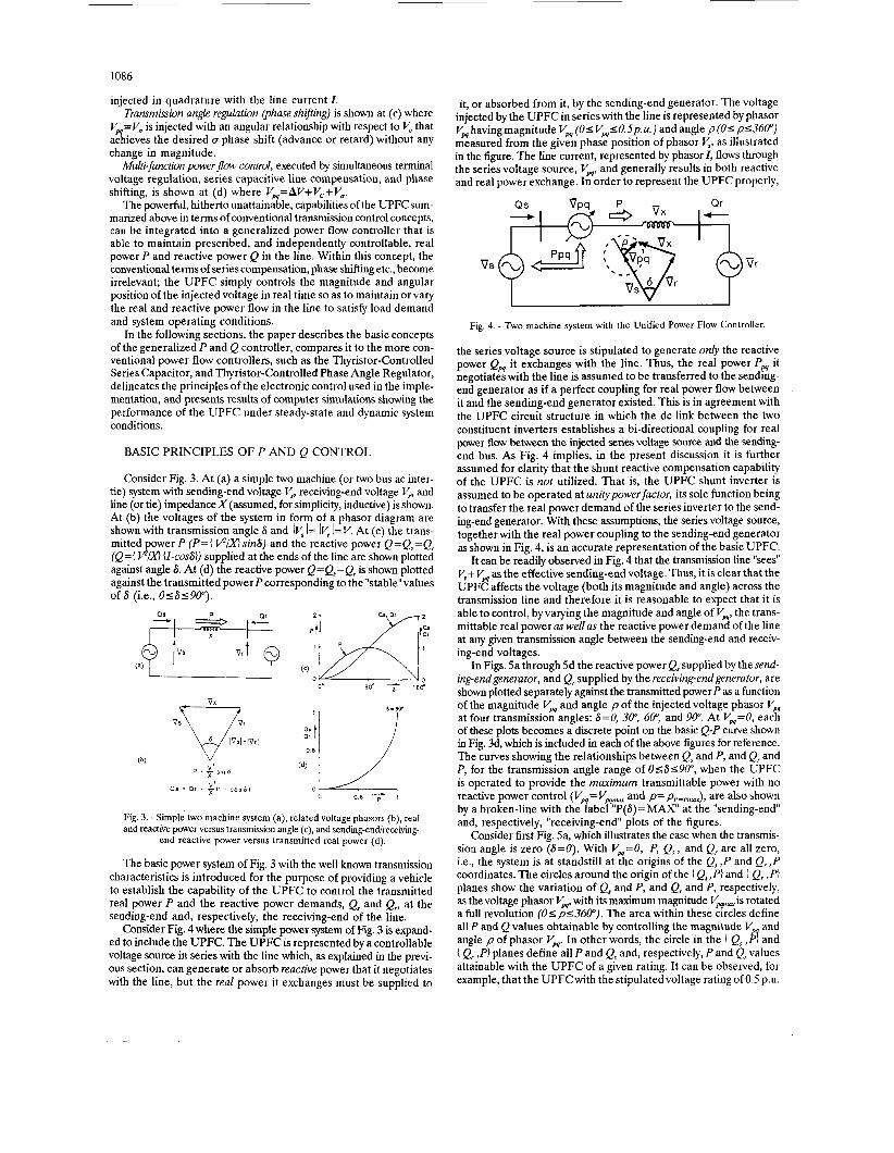
Consider Fig. 3. At (a) a simple two machine (or two bus ac inter- tie) system with sending-end voltage V,, receiving-end voltage V,, and line (or tie) impedanceX(assumed, for simplicity, inductive) is shown. At (b) the voltages of the system in form of a phasor diagram are shown with transmission angle S and IV, I = IV, l=V. At (c) the trans- mitted power P (P={ V?/HsinS) and the reactive power Q=Q,=Q, (e={ U-cosS)) supplied at the ends of the line are shown plotted against angle S. At (d) the reactive power Q=Q,=Q, is shown plotted against the transmitted power P corresponding to the "stable" values of S (i.e., 0 ~ 6 1 9 0 " ) .
Fig. 3. - Simple two machine system (a), related voltage phasors (b), real and reactive power versus transmission angle (c), and sending-endlreceiving-
end reactive power versus transmitted real power (d).
The basic power system of Fig. 3 with the well known transmission characteristics is introduced for the purpose of providing a vehicle to establish the capability of the UPFC to control the transmitted real power P and the reactive power demands, Q, and Q,, at the sending-end and, respectively, the receiving-end of the line.
Consider Fig. 4 where the simple power system of Fig. 3 is expand- ed to include the UPFC. The UPFC is represented by a controllable voltage source in series with the line which, as explained in the previ- ous section, can generate or absorb reactive power that it negotiates with the line, but the real power it exchanges must be supplied to
it, or absorbed from it, by the sending-end generator. The voltage injected by the UPFC in series with the line is represented by phasor V,havingmagnitude Vw (O<V,<O.Sp.u.) and angle p(O<p<36@') measured from the given phase position of phasor as illustrated in the figure. The line current, represented by phasor I , flows through the series voltage source, V,, and generally results in both reactive and real power exchange. In order to represent the UPFC properly,
-
Fig. 4. - Two machine system with the Unified Power Flow Controller.
the series voltage source is stipulated to generate only the reactive power Q, it exchanges with the line. Thus, the real power P, it negotiates with the line is assumed to be transferred to the sending- end generator as if a perfect coupling for real power flow between it and the sending-end generator existed. This is in agreement with the UPFC circuit structure in which the dc link between the two constituent inverters establishes a bi-directional coupling for real power flow between the injected series voltage source and the sending- end bus. As Fig. 4 implies, in the present discussion it is further assumed for clarity that the shunt reactive compensation capability of the UPFC is not utilized. That is, the UPFC shunt inverter is assumed to be operated at unitypower factor, its sole function being to transfer the real power demand of the series inverter to the send- ing-end generator. With these assumptions, the series voltage source, together with the real power coupling to the sending-end generator as shown in Fig. 4, is an accurate representation of the basic UPFC.
It can be readily observed in Fig. 4 that the transmission line "sees" V,+ V, as the effective sending-end voltage. Thus, it is clear that the UPFC affects the voltage (both its magnitude and angle) across the transmission line and therefore it is reasonable to expect that it is able to control, by varying the magnitude and angle of V', the trans- mittable real power as well as the reactive power demand of the line at any given transmission angle between the sending-end and receiv- ing-end voltages.
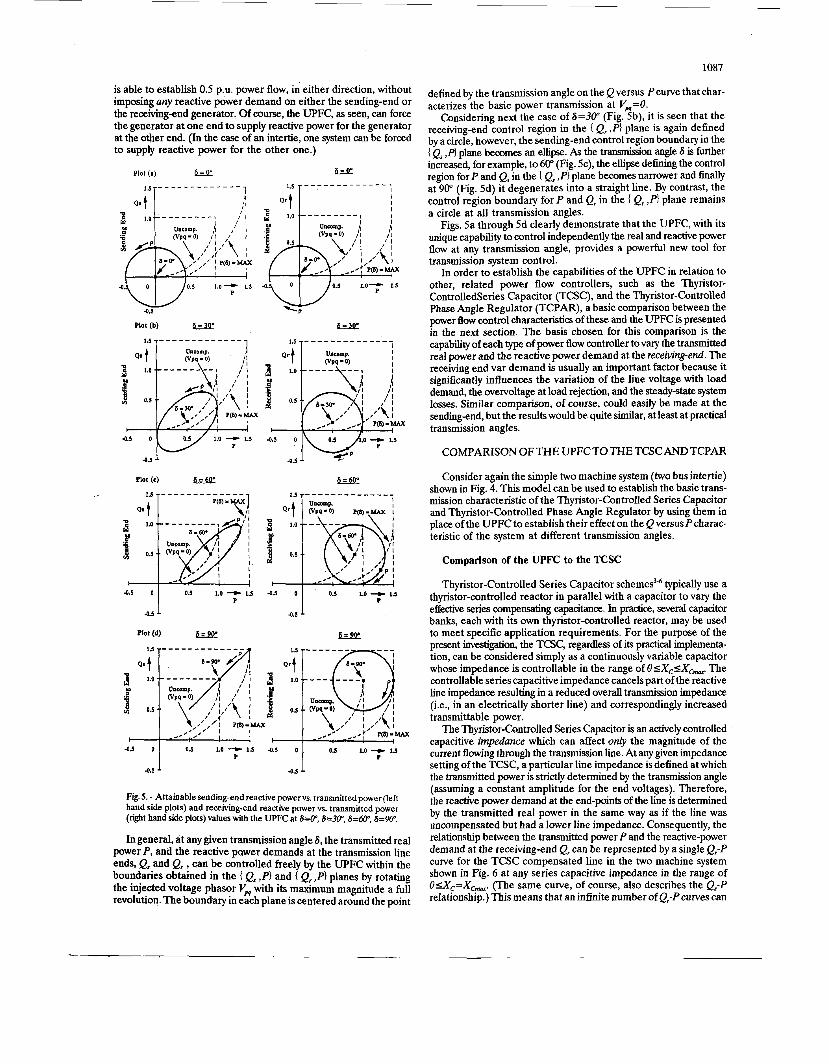
In Figs. 5a through 5d the reactive power Q, supplied by thesend- ing-endgenerator, and Q, supplied by the receiving-end generator, are shown plotted separately against the transmitted powerP as a function of the magnitude V, and angle p of the injected voltage phasor V, at four transmission angles: S=O, 30", 604 and 90". At Vw=O, each of these plots becomes a discrete point on the basic Q-P curve shown in Fig. 3d, which is included in each of the above figures for reference. The curves showing the relationships between Qs and P, and Q, and P, for the transmission angle range of 0 ~ 6 1 9 @ ' , when the UPFC is operated to provide the maximum transmittable power with no reactive power control (V,=V,,- and p=pP+,,,), are also shown by a broken-line with the label "P(S)=MAX" at the "sending-end'' and, respectively, "receiving-end" plots of the figures.
Consider first Fig. 5a, which illustrates the case when the transmis- sion angle is zero (S=O). With V,=O, P, Q, and Q, are all zero, i.e., the system is at standstill at the origins of the Q, ,P and Q, ,P coordinates. The circles around the origin of the 1 Qs,P} and { Q, ,PI planes show the variation of Qs and P, and Q, and P, respectively, as the voltage phasor V', with its maximum magnitude VF is rotated a full revolution (O<pS360"). The area within these circles define all P and Q values obtainable by controlling the magnitude V and angle p of phasor V,. In other words, the circle in the { Q, ,d and { Q, ,P} planes define all P and Q, and, respectively, P and Q, values attainable with the UPFC of a given rating. It can be observed, for example, that the UPFCwith the stipulatedvoltage rating of 0.5 p.u.
1087
is able to establish 0.5 p.u. power flow, in either direction, without imposing any reactive power demand on either the sending-end or the receiving-end generator. Of course, the UPFC, as seen, can force the generator at one end to supply reactive power for the generator at the other end. (In the case of an intertie, one system can be forced to supply reactive power for the other one.)
Plot (b)
1.5
Qrt w' 1.0 M
> r +.<
-0.s 0 p 1.0 - P 1.5
-03
-0.5 0 y q i o y 1.5
4.5
Qr t 3 1.0
0.5
c-
P 0.5 1.0 --c 1.5 -0.5
O I -0.1 J. 4.5 1
Fig. 5. - Attainable sending-end reactive power vs. transmittedpower (left hand side plots) and receiving-end reactive power vs. transmitted power (right hand side plots) values with the UPFC at S i @ , S=3@, 6=W, 6=W.
In general, at any given transmission angle 6, the transmitted real power P, and the reactive pawer demands at the transmission line ends, Q, and Qr , can be controlled freely by the UPFC within the boundaries obtained in the { 12, ,PI and { Q, ,PI planes by rotating the injected voltage phasor Vp4 with its maximum magnitude a full revolution. The boundary in each plane is centered around the point
defined by the transmission angle on the Q versus Pcurve that char- acterizes the basic power transmission at V,=O.
Considering next the case of S=3ff (Fig. Sb), it is seen that the receiving-end control region in the { Q, ,PI plane is again defined by a circle, however, the sending-end control region boundary in the I Q, ,PI plane becomes an ellipse. As the transmission angle S is further increased, for example, to 60" (Fig. Sc), the ellipse defining the control region for P and Qs in the { Q, ,PI plane becomes narrower and finally at 90" (Fig. Sd) it degenerates into a straight line. By contrast, the control region boundary for P and Q, in the ( Q, ,f'} plane remains a circle at all transmission angles.
Figs. Sa through 5d clearly demonstrate that the UPFC, with its unique capability to control independently the real and reactive power flow at any transmission angle, provides a powerful new tool for transmission system control.
In order to establish the capabilities of the UPFC in relation to other, related power flow controllers, such as the Thyristor- ControlledSeries Capacitor (TCSC), and the Thyristor-Controlled Phase Angle Regulator (TCPAR), a basic comparison between the power flow control characteristics of these and the UPFC is presented in the next section. The basis chosen for this comparison is the capability of each type of power flow controller to vary the transmitted real power and thereactive power demand at the receiving-end. The receiving end var demand is usually an important factor because it significantly influences the variation of the line voltage with load demand, the overvoltage at load rejection, and the steady-state system losses. Similar comparison, of course, could easily be made at the sending-end, but the results would be quite similar, at least at practical transmission angles.
COMPARISON O F THE UPFC TO THE TCSC AND TCPAR
Consider again the simple two machine system (two bus intertie) shown in Fig. 4. This model can be used to establish the basic trans- mission characteristic of the Thyristor-Controlled Series Capacitor and Thyristor-Controlled Phase Angle Regulator by using them in place of the UPFC to establish their effect on the Q versus Pcharac- teristic of the system at different transmission angles.
Comparison of the UPFC to the TCSC
Thyristor-Controlled Series Capacitor scheme^^.^ typically use a thyristor-controlled reactor in parallel with a capacitor to vary the effective series compensating capacitance. In practice, several capacitor banks, each with its own thyristor-controlled reactor, may be used to meet specific application requirements. For the purpose of the present investigation, the TCSC, regardless of its practical implementa- tion, can be considered simply as a continuously variable capacitor whose impedance is controllable in the range of OSX&X- The controllable series capacitive impedance cancels part of the reactive line impedance resulting in a reduced overall transmission impedance (i.e., in an electrically shorter line) and correspondingly increased transmittable power.
The Thyristor-Controlled Series Capacitor is an actively controlled capacitive impedance which can affect only the magnitude of the current flowing through the transmission line. At any given impedance setting of the TCSC, a particular line impedance is defined at which the transmitted power is strictly determined by the transmission angle (assuming a constant amplitude for the end voltages). Therefore, the reactive power demand at the end-points of the line is determined by the transmitted real power in the same way as if the line was uncompensated but had a lower line impedance. Consequently, the relationship between the transmitted power P and the reactive-power demand at the receiving-end Q, can be represented by a single Qr-P curve for the TCSC compensated line in the two machine system shown in Fig. 6 at any series capacitive impedance in the range of OsX,=X- (The same curve, of course, also describes the Q,-P relationship.) This means that an infinite number of Q,-Pcuwes can
1088
Fig. 6. - Two machine system with the Thyristor-Controlled Series Capacitor
be established by using the basic transmission relationships, i.e., P={ V'/(X-XJ} sin8 and e,=( V'/(X-X,)} (l-cosS} , with X, varying between 0 and X - Evidently, a given transmission angle defines a single point on each Qr-P curve obtained with a specific value of X,. Thus, the progressive increase of X, from zero to Xcm could be viewed as if the point, defining the corresponding P and Q,values at the given transmission angle on the first Q,-P curve which represents the power transmission with no compensation (X,=O), moves through an infinite number of Q,-P curves representing progressively increasing series compensation until it finally reaches the last Q,-P curve that represents the power transmisjion with maximum series compensation. The first Qr-P curve, representing the uncompensated power transmis- sion, may be considered as the lower boundary curve and identified by (Q,-P),-,. The last Q,-P curve, representing the power transmission with maximum series compensation, may be considered as the upper boundary curve and identified by (e,-P),,,. Note that, as before, all Q,-P curves are considered only for the "stable" range of the trans- mission angle ( 0 ~ 6 ~ 9 0 " ) .
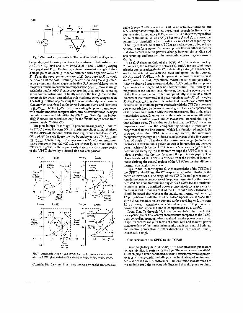
The plots in Figs. 7a through 7d present the range of Q,-Pcontrol for TCSC, having the same 0.5 p a . maximum voltage rating stipulated for the UPFC, at the four transmission angles considered: S=P, 304 604 and 90". In each figure the two boundary curves, (Q,-P),owe, and (Q,-P),+,,,, representing zero compensation (X,=O) and maximum series compensation (X,=X&, are shown by a broken-line for reference, together with the previously derived circular control region of the UPFC shown by a dotted-line for comparison.
Plot (a) 6=0" Plot (b) k,W
Control Region
far UPFC
/ 6=30° ,\ I,'
-0.5 0 ', 0.5 4.0 1.5
Control
for TCSC 4.5 - p Interval
Plot (d) Plot (e) 6=60'
0.5 1.0 17 1.5 4.5 0.5 1.0 7 1.5
Control 4.5 Intrrvd
for TCSC
Fig. 7. - Attainable Q, and P values with the TCSC (heavy line) and those with the UPFC (inside dashed-line circle) at S=Oq 6=304 6=604 6=904
Consider Fig. 7a which illustrates the case when the transmission
angle is zero (S=O). Since the TCSC is an actively-controlled, but functionallypassive impedance, the current through the line with the compensated impedance (X-XJ remains invariably zero, regardless of the of the actual value of X,. Thus both P and Q, are zero, the system is at standstill, which condition cannot be changed by the TCSC. By contrast, since the UPFC is an actively-controlled voltage source, it can force up to 0.5 p.u. real power flow in either direction and also control reactive power exchange between the sending-end and receiving-end buses within the circular control region shown in the figure.
The Q,-P characteristic of the TCSC at 6=3@ is shown in Fig. 7b. As seen, the relationship between Q, and P, for the total range of series compensation, OSSSW, is defined by a straight line connect- ing the two related points on the lower and upper boundary curves, (Q,-P),owe, and (Q,-P),p,, which represent the power transmission at S =30", with zero and, respectively, maximum series compensation. It can be observed that, as expected, the TCSC controls the real power by changing the degree of series compensation (and thereby the magnitude of the line current). However, the reactive power demand of the line cannot be controlled independently; it remains a direct function of the transmitted real power obtained at S=3@ with valying X , ( O s X C a & . It is also to be noted that the achievable maximum increase in transmittable power attainable with the TCSC is a constant percentage (defined by the maximum degree of series compensation) of the power transmitted with the uncompensated line at the given transmission angle. In other words, the maximum increase attainable in actual transmitted power is much less at small transmission angles than at large ones. This is due to the fact that the TCSC is a series impedance and thus the compensating voltage it produces is proportional to the line current, which is a function of angle S. By contrast, since the UPFC is a voltage source, the maximum compensating voltage it produces is independent of the line current (and of angle 8) . Therefore the maximum change (increase or decrease) in transmittable power, as well as in receiving-end reactive power, achievable by the UPFC is not a function of angle S and is determined solely by the maximum voltage the UPFC is rated to inject in series with the line (assumed 0.5 p.u. in this paper). This characteristic of the UPFC is evident from the circles of identical radius defining the control regions of the UPFC for the four different transmission angles considered.
Figs. 7c and 7d, showing the Q,-Pcharacteristics of the TCSC and the UPFC at S=60" and S=90", respectively, further illustrates the above observations. The range of the TCSC for real power control remains a constant percentage of the power transmitted by the uncom- pensated line at all transmission angles (OSSSW), but the maximum actual change in transmitted power progressively increases with in- creasing S and it reaches that of the UPFC at &=go". However, it should be noted that whereas the maximum transmitted power of 1.5 P.u., obtained with the TCSC at full compensation, is associated with 1.5 p.u. reactive power demand at the receiving-end, the same 1.5 p.u. power transmission is achieved only with 1.0 p.u. reactive power demand when the line is compensated by a UPFC.
From Figs. 7a through 7d, it can be concluded that the UPFC has superior power flow control characte&tics compared to the TCSC it can control independently both real and reactive power over a broad range, its control range in terms of actual real and reactive power is independent of the transmission angle, and it can control both real and reactive power flow in either direction at zero (or at a small) transmission angle.
Comparison of the UPFC to the TCPAR
Phase Angle Regulators (PARS) provide controllable quadrature voltage injection in series with the line. The commercially available PARS employ a shunt-connected evcitatwn transformer with appropri- ate taps on the secondary windings, a mechanical tap-changing gear, and a series insertion transformer. The excitation transformer has wye to delta (or delta to wye) windings and thus the phase to phase
1089
secondary voltages are in quadrature with respect to the corresponding primary phase to neutral voltages. These voltages, via the tap-changing gear and the series insertion transformer, are injected in series with the appropriate phases of the line. As a result, the two sets of three- phase voltages, obtained at the two ends of the series insertion trans- former, are phase shifted with respect to each other by an angle a, where o=tan-'(V, w; Vu is the magnitude of the series injected volt- age and Vis the magnitude of the line voltage (phase to neutral). Since the voltage injection can be of either polarity, amay represent either phase advance or retard.
The Thyristor-Controlled Phase Angle Regulators (TCPARs) are functionaUy similar to the conventional PARS, except
for the mechanical tap-changer which is replaced by.an appropriate thyristor switch arrangement. Like their mechanically-controlled counterparts, they also provide controllable, bi-directional, quadrature voltage injection. However, their control can be continuous or step- like, but the continuous control is usually associated with some har- monic generation. For the purpose of the present investigation, the practical implementation of the TCPAR is unimportant. For simplicity, the TCPAR is considered as an ideal phase angle regulator, which is able to vary continuously the phase angle between the voltages at the two ends of the insertion transformer in the control range of -am~asa,,without changing the magnitude of the phase shifted voltage from that of the original line voltage.
A basic, and in the present investigation important, attribute of all conventional (mechanical and thyristor-controlled) phase angle regulators, including the ideal one stipulated above, is that the total VA (i.e., both the real power and the vars) exchanged by the series insertion transformer appears at the primary of the excitation trans- former as a load demand on the power system. Thus, both the real and the reactive power the phase angle regulator supplies to, or absorbs from, the line when it injects the quadrature voltage must be absorbed from it, or supplied to it by the ac system. By contrast, the UPFC itself generates the reactive power part of the total VA it exchanges as a result of the series voltage injection and it presents only the real power part to the ac system as a load demand.
Consider Fig. 8 where the previously considered two machine system shown again with a TCPAR assumed to function as an ideal phase angle regulator. For this, the transmitted power, and the reac- tive power demands at the sending-end and receiving-end, can be described by relationships analogous to those characterizing the un- compensated) system: P={ V'/XlsinS' and Qr=Q,={ V/Xl U-cosS3,
VS
Qr
I 1 I
Fig. 8. - Two machine system with the Thyristor-Controlled Phase Angle Regulator.
where S'=S-a. Thus, it is clear that the TCPAR cannot increase the maximum transmittable power, P=V'/X, or change Q, at a fixed P. Consequently, the Q,-P relationship, with transmission angle 8' (OS~'SW) controlling the actual power transmission, is identical to that of the uncompensated system shown in Fig. 3d. The function of the TCPAR is simply to establish the actual transmission angle S', required for the transmission of the desired powerP, by adjusting the phase-shift angle a so as to satisfy the equation S'=S-a at a given S, the angle existing between the sending-end and receiving-end volt- ages. In other words, the TCPAR can vary the transmitted power at a fixed 6, or maintain the actual transmission angle 8' constant in the face of a varying 6, but it cannot control the reactive power
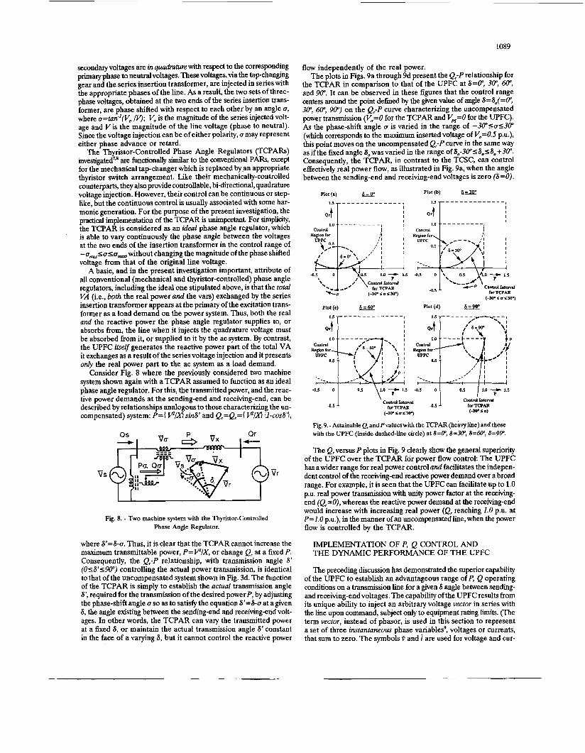
flow independently of the real power. The plots in Figs. 9a through 9d present the Ql-P relationship for
the TCPAR in comparison to that of the UPFC at S=P, 30", 604 and W. It can be observed in these figures that the control range centers around the point defined by the given value of angle S=So(=O", 30", 604 90") on the Q,-P curve characterizing the uncompensated power transmission (V,=O for the TCPAR and VM=O for the UPFC). As the phase-shift angle a is varied in the range of -30"Sa~30" (which corresponds to the maximum inserted voltage of V,=O.S P.u.), this point moves on the uncompensated Qr-P curve in the same way as if the fixed angle So wasvaried in the range of S,-30"SS0~S,+30". Consequently, the TCPAR, in contrast to the TCSC, can control effectively real power flow, as illustrated in Fig. 9a, when the angle between the sending-end and receiving-end voltages is zero (S=O).
Plot (a) 6=0' Plot(b)
I I I
Contml t I I COOtrOl t - - - - - - - - - J I 1.0 - - - - _ _ _ _ _ I
4.5 +*:.. (-w s a 5 30-)
Plot@) 1=60" Plot (d) k..w
4.5 0 I 0.5 \1.0 7 1.5 4.5 0 1 0.5 I 1.0 ---c 1.5
1 \
4.5
Fig.9.-AttainableQ,andPvalueswith theTCPAR(heavy1ine)andthose with the UPFC (inside dashed-line circle) at S=Oq S=3U', S=604 8=9@.
The Qr versus P plots in Fig. 9 clearly show the general superiority of the UPFC over the TCPAR for power flow control: The UPFC has awider range for real power control and facilitates the indepen- dent control of the receiving-end reactive power demand over a broad range. For example, it is seen that the UPFC can facilitate up to 1.0 p.u. real power transmission with unity p e r factor at the receiving- end (Ql=O), whereas the reactive power demand at the receiving-end would increase with increasing real power (Q, reaching 1.0 p.u. at P = L O P.u.), in the manner of an uncompensated line, when the power flow is controlled by the TCPAR.
IMPLEMENTATION OF P, Q CONTROL AND THE DYNAMIC PERFORMANCE OF THE UPFC
The preceding discussion has demonstrated the superior capability of the UPFC to establish an advantageous range of P, Q operating conditions on a transmission line for a given S angle between sending- and receiving-end voltages. The capability of the UPFC results from its unique ability to inject an arbitrary voltage vector in series with the line upon command, subject only to equipment rating limits. (The term vector, instead of phasor, is used in this section to represent a set of three instantaneous phase v?riables9, voltages or currents, that sum to zero. The symbols 0 and i are used for voltage and cur-
1090
rent vectors.) Because of its electronic controls, the UPFC can cause the series-injected voltage vector to vary rapidly and continuously in magnitude and/or angle as desired. It is thus not only able to estab- lish an operating point within a wide range of possible P, Q conditions on the line, but also has the inherent capability to transition rapidly from one such achievable operating point to another.
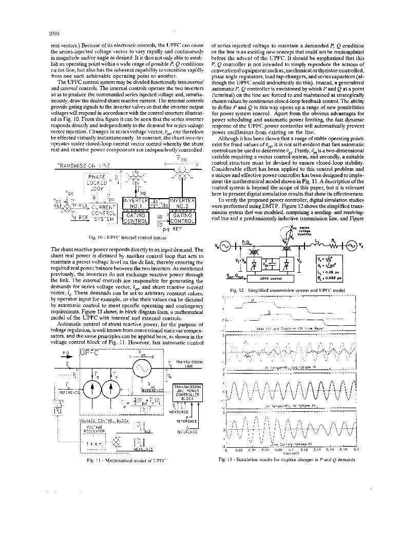
The UPFC control system may be divided functionally into intemal and ertemal controls. The internal controls operate the two inverters so as to produce the commanded series injected voltage and, simulta- neously, draw the desired shunt reactive current. The internal controls provide gating signals to the inverter valves so that the inverter output voltageswill respond in accordance with the control structure illustrat- ed in Fig. 10. From this figure it can be seen that the series inverter responds directly and independently to the demand for series voltage vector injection. Changes in series voltage vector, UN, can therefore be effected virtually instantaneously. In contrast, the shunt inverter operates under closed-loop current vector control whereby the shunt real and reactive power components are independently controlled.
N
v P 9 TRAN SM lSS l0 N LINE
~ PHASE +;,I T * i LOCKED 11 L'w
Pq REF Fig. 10 - UPFC internal control system
The shunt reactive power responds directly to an input demand. The shunt real power is dictated by another control loop that acts to maintain a preset voltage level on the dc link, thereby ensuring the required real power balance between the two inverters. As mentioned previously, the inverters do not exchange reactive power through the link. The extemal controls are responsible for generating the demancis for series voltage vector, Om, and shunt reactive current vector, jq . These demands can be set to arbitrary constant values, by operator input for example, or else their values can be dictated by automatic control to meet specific operating and contingency requirements. Figure 11 shows, in block diagram form, a mathematical model of the UPFC with internal and external controls.
Automatic control of shunt reactive power, for the purpose of voltage regulation, is well known from conventional staticvar compen- sators, and the same principles can be applied here, as shown in the voltage control block of Fig. 11. However, fast automatic control
............................................ - % I U P F C k L > ~
! '? TRANSMISSION
4 TRANSMISSION I L I N E POWER CONTROLLER
BL3CK
M E A S U R E D
yoLL.AcE. .c 041 EI9.L. B L W ,
R E F E R E N C E ~ VOLTAGE i R E G U L A T O R
of series injected voltage to maintain a demanded P, Q condition on the line is an exciting new concept that could not be contemplated before the advent of the UPFC. It should be emphasized that this P, Q controller is not intended to simply reproduce the actions of conventional equipment such as, mechanical or thyristor-controlled, phase angle regulators, load tap-changers, and series capacitors (al- though the UPFC could undoubtedly do this). Instead, a generalized automatic P, Q controller is envisioned by which P and Q at a point (terminal) on the line are forced to and maintained at strategically chosen values by continuous closed-loop feedback control. The ability to define P and Q in this way opens up a range of new possibilities for power system control. Apart from the obvious advantages for power scheduling and automatic power limiting, the fast dynamic response of the UPFC power controller will automatically prevent power oscillations from existing on the line.
Although it has been shown that a range of stable operating points exist for fixed values of UN, it is not self-evident that fast automatic control can be used to determine UN. Firstly, PM is a two-dimensional variable requiring a vector control system, and secondly, a suitable control structure must be devised to ensure closed-loop stability. Considerable effort has been applied to this control problem and a unique and effective power controller has been designed to imple- ment the mathematical model shown in Fig. 11. A description of the control system is beyond the scope of this paper, but it is relevant here to present digital simulation results that show its effectiveness.
To verify the proposed power controller, digital simulation studies were performed using EMTP. Figure 12 shows the simplified trans- mission system that was modeled, comprising a sending- and receiving- end bus and a predominantly inductive transmission line, and Figure
Inlmotlon
I I I ' I
Fig. 12 - Simplified transmission system and UPFC model 2 1 ' ' ' ' I ' ' ' ' i ' ' ' ~ ' " " " " " " " " " " " " " " " "
0
Fig. 13 - Simulation results for steplike changes in P and Q demands
1091
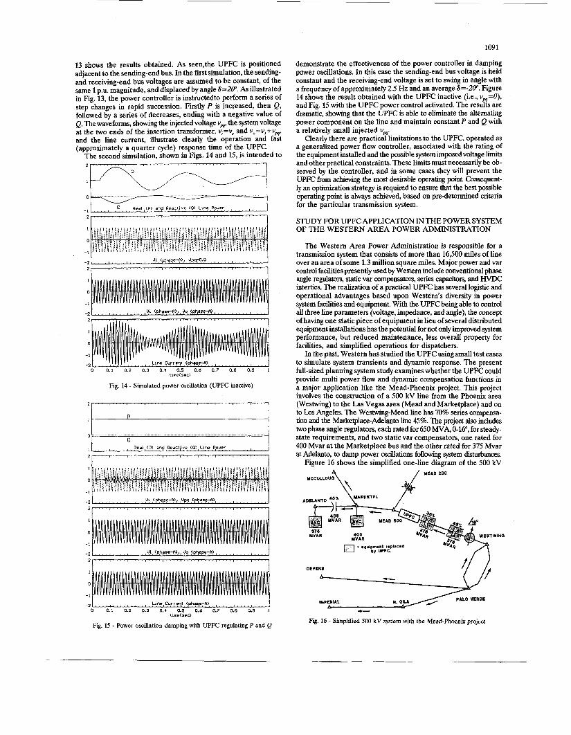
demonstrate the effectiveness of the power controller in damping power oscillations. In this case the sending-end bus voltage is held constant and the receiving-end voltage is set to swing in angle with a frequency of approximately 2.5 Hz and an average S=-20". Figure 14 shows the result obtained with the UPFC inactive (i.e., vw=O), and Fig. 15 with the UPFC power control activated. The results are dramatic, showing that the UPFC is able to eliminate the alternating power component on the line and maintain constant P and Q with a relatively small injected vw.
Clearly there are practical limitations to the UPFC, operated as a generalized power flow controller, associated with the rating of the equipment installed and the possible system imposed voltage limits and other practical constraints. These limits must necessarily be ob- served by the controller, and in some cases they will prevent the UPFC from achieving the mast desirable operating point. Consequent- ly an optimization strategy is required to ensure that the best possible operating point is always achieved, based on pre-determined criteria for the particular transmission system.
STUDY FOR UPFC APPLICATION IN THE POWER SYSTEM OF THE WESTERN AREA POWER ADMINISTRATION
61
I - . . . . I . . . . I . . . , I , . . . . . . . . . . . I . . . . ) . . . . I . . . . 8 . . . . Real (P) anp Reactjve ( 0 ) Line Pouer
13 shows the results obtained. As seen,the UPFC is positioned adjacent to the sending-end bus. In the first simulation, the sending- and receiving-end bus voltages are assumed to be constant, of the same 1 p.u. magnitude, and displaced by angle S=20". As illustrated in Fig. 13, the power controller is instructedto perform a series of step changes in rapid succession. Firstly P is increased, then Q, followed by a series of decreases, ending with a negative value of Q. The waveforms, showing the injected voltage vp4, the system voltage at the two ends of the insertion transformer, v,=v, and v,=v,+v,, and the line current, illustrate clearly the operation and fast (approximately a quarter cycle) response time of the UPFC.
The second simulation, shown in Figs. 14 and 15, is intended to
Real (P) an Reacl ve ( 0 ) Line Pouer - 1
I
0
-1
1
0
-1
-2 ' ' , ! l I ! l ' , ' , Linp,Currsqt cphap;A) . . .
Fig. 15 - Power oscillation damping with UPFC regulating P and Q
The Western Area Power Administration is responsible for a transmission system that consists of more than 16,500 miles of line over an area of some 1.3 million square miles. Major power and var control facilities presently used by Western include conventional phase angle regdatoxs, static var compensators, series capacitoxs, and HVDC interties. The realization of a practical UPFC has several logistic and operational advantages based upon Westem's diversity in power system facilities and equipment. With the UPFC being able to control all three line parameters (voltage, impedance, and angle), the concept of having one static piece of equipment in lieu of several distributed equipment installations has the potential for not only improved system performance, but reduced maintenance, less overall property for facilities, and simplified operations for dispatchers.
In the past, Western has studied the UPFC using small test cases to simulate system transients and dynamic response. The present full-sized planning system study examines whether the UPFC could provide multi power flow and dynamic compensation functions in a major application like the Mead-Phoenix project. This project involves the construction of a 500 kV line from the Phoenix area (Westwing) to the Las Vegas area (Mead and Marketplace) and on to Los Angeles. The Westwing-Mead line has 70% series compensa- tion and the Marketplace-Adelanto line 45%. The project also includes two phase angle regulators, each rated for 650 MVA, 0-16", for steady- state requirements, and two static var compensators, one rated for 400 Mvar at the Marketplace bus and the other rated for 375 Mvar at Adelanto, to damp power oscillations following system disturbances.
Figure 16 shows the simplified one-line diagram of the 500 kV
MCCULLOUa \ MEAD 230 4 ADELANTO ?'? \Y*RKETPL /
DEVERS
IMPERIAL - Fig. 16 - Simplified 500 kV system with the Mead-Phoenjx projeci
2.00
1.75
and superior dynamic performance. Further studies are planned which will focus on finding an effective combination of the UPFC and con- ventional equipment (e.g., series capacitors), and on the application of improved control algorithms, in order to come up with the best trade-off between cost and performance.
I . . . . I . ' ' 8 " I ' , ' " I " ' I ' " T " " ~ ' " ' I ' ' '
Cor lvent lona! -
CONCLUSIONS
The Unified Power Flow Controller, from the viewpoint of conven- tional transmission compensation and control, is an apparatus that can provide simullaneou, real-time control of all or any combination of the basic power system parameters (transmission voltage, line impedance and phase angle) which determine the transmittable power. However, the UPFC can also be viewed as a generalized real and reactive power flow controller that is able to maintain a prescribed P and Q at a given point (bus) on the transmission line. As is shown in the paper, a broad range of P and Q control is achievable with reasonable UPFC rating. The computer simulations indicate that the attainable response of the control is very fast, almost instanta- neous, and thus the UPFC is extremely effective in handling dynamic system disturbances.
The UPFC provides a flexibility for ac power transmission control that has been hitherto achievable only by HVDC transmission. Strate- gically chosen and adjustable P and Q values, representing steady-state and temporaxy p w e r system requirements and contingency conditions, can be forced to and maintained at a given point on the transmission system by continuous closed-loop feedback control. Apart from the obvious advantages for power scheduling and automatic power limit- ing, the UPFC will also automatically counteract power oscillations and can adapt almost instantaneously to new P and Q dem'ands to enhance the transient behavior of the system and optimize its perfor- mance under transmission contingency conditions. ill t
ACKNOWLEDGEMENTS
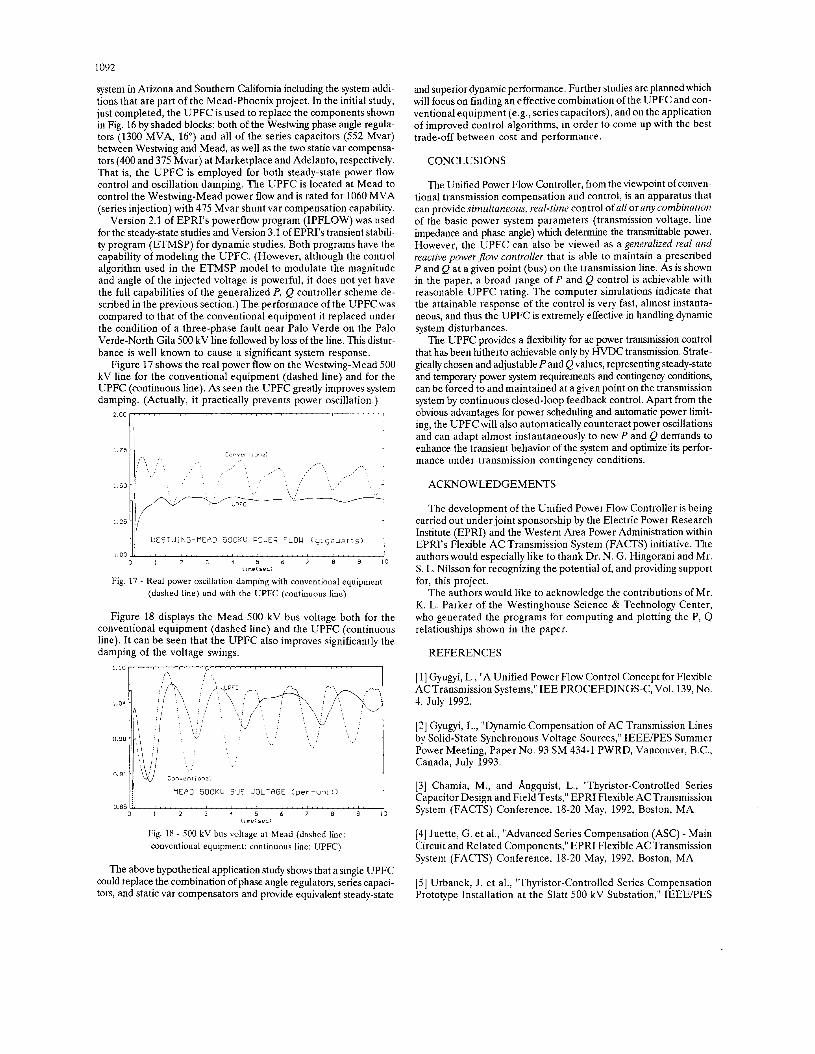
/ / I W E S T W I N G - R E A D 53OXU POWER FLOW (giqauatts) 1 11me(sec)
Fig. 17 - Real power oscillation dampmg with conventlonal equipment (dashed line) and with the UPFC (continuous line)
Figure 18 displays the Mead 500 kV bus voltage both for the conventional equipment (dashed line) and the UPFC (continuous line). It can be seen that the UPFC also improves significantly the damping of the voltage swings.
0.85 : . , . i , , , . I . . , I . . . . ) , , . . I . , . . I . . . . I . . . . I . , . . N . ' . ,
0 I 2 3 4 5 6 7 8 9 10 1 I me( sec)
Fig. 18 - 500 kV bus voltage at Mead (dashed line: conventional equipment: continuous line: UPFC)
The above hypothetical application study shows that a single UPFC could replace the combination of phase angle regulators, series capaci- tors, and static var compensators and provide equivalent steady-state
The development of the Unified Power Flow Controller is being carried out under joint sponsorship by the Electric Power Research Institute (EPRI) and the Western Area Power Administration within EPRI's Flexible AC Transmission System (FACTS) initiative. The authors would especially like to thank Dr. N. G. Hingorani and Mr. S. L. Nilsson for recognizing the potential of, and providing support for, this project.
The authors would like to acknowledge the contributions of Mr. K. L. Parker of the Westinghouse Science & Technology Center, who generated the programs for computing and plotting the P, Q relationships shown in the paper.
REFERENCES
[l] Gyugyi, L., "A Unified Power Flow Control Concept for Flexible AC Transmission Systems," IEE PROCEEDINGS-C, Vol. 139, No. 4, July 1992.
[2] Gyugyi, L., "Dynamic Compensation of AC Transmission Lines by Solid-state Synchronous Voltage Sources," IEEEPES Summer Power Meeting, Paper No. 93 SM 434-1 PWRD, Vancouver, B.C., Canada, July 1993.
[3] Chamia, M., and Angquist, L., "Thyristor-Controlled Series Capacitor Design and Field Tests," EPRI Flexible ACTransmission System (FACTS) Conference, 18-20 May, 1992, Boston, MA.
[4] Juette, G. et al., "Advanced Series Compensation (ASC) - Main Circuit and Related Components," EPRI Flexible ACTransmission System (FACTS) Conference, 18-20 May, 1992, Boston, MA.
[5] Urbanek, J. et al., "Thyristor-Controlled Series Compensation Prototype Installation at the Slatt 500 kV Substation," IEEE/PES
1093
Summer Meeting, Paper No. 92 SM 467-1 PWRD, Seattle, WA, July 1992.
[6] Larsen, E. V., e t al., “Characteristics and Rating Considerations of Thyristor-Controlled Series Compensation,” IEEEPES Summer Meeting, Paper No. 93 SM 433-3 PWRD, Vancouver, B.C., Canada, July 1993.
[7] Baker, R. and Guth, G., “Control Algorithm for a Static Phase Shifting Transformer to Enhance Transient and Dynamic Stability of Large Power Systems,” IEEE Transactions on Power Apparatus and Systems, Vol. PAS-101, No. 9, September 1982, pp. 3532-3541.
[8] Wood, P., e t al., “Study of Improved Load Tap-Changing for Transformers and Phase-Angle regulators,” EPRI Report EL-6079, Project 2763-1, 1988.
[9] Schauder, C. D. and Mehta, H., “Vector Analysis and Control of Advanced Static Var Compensators,” IEE PROCEEDINGS-C, Vol. 140, No. 4, July 1993.
BIOGRAPHIES
Laszlo Cyugyi (IEE P 1976) received his undergraduate education at the University of Technology, Budapest, further studied mathematics at the University of London, England, and electrical engineering both at the University of Pittsburgh, PA (M.S.E.E. 1967) and at the University of Salford, England (Ph.D. 1970). He joined the Westinghouse Science & Technology Center in 1963, where he is now the manager of the Power Electronics Department and responsible for technology and product development in this area. Dr. Gyugyi has a broad experience in all areas of power conversion and control, and has been pioneering advanced power electroniobased compensation and control techniques for utility applications, for which e k r t he received the Westinghouse Order of Merit (the corporation’s highest honor) in 1992.
Colin D. Schauder (M’1981) was born in Port Elizabeth, South Africa, in 1952. He was awarded the B.Sc. Engineering and Ph.D. degrees by the University of Cape Town, South Africa, in 1972 and 1978, respectively. From 1978 to 1983 he was employed by GEC Industrial Controls in Rugby, England. In 1983 he joined the Westinghouse Science & Technology Center where he is now an Advisory Engineer in the Power Electronics Department. His work has man@ been involved with high performance ac motor drives and the design and control of advanced power conversion systems.
Scott L. Williams was born in Torrance, California, in 1963. He obtained a B.S.E.E. from Wilkes College, Wilkes-Barre, PAin 1985 and the M.S.E.E. degree from Clarkson University, Potsdam, NY in 1986. He has seven years experience in the areas of closed-loop feedback control systems, real-time embedded microprocessor applications, analog and digital circuit design, and detailed system analysis and simulation. He joined the Westinghouse Science & Technology Center in 1992 where he is a Senior Engineer in the Power Electronics Department. He is currently developing a detailed hardware TNA scale model of the UPFC to rigorously test and evaluate control and protection strategies.
Thomas R. Rietman (M’) was born in central Minnesota. He received his B.S.E.E. degree from the University of Colorado and his M.S.E.E. degree from the University of Minnesota. After receiving the M.S.E.E. degree, he obtained a position at the Bonnede Power Administration in Portland, Oregon, where he worked for 17 years in both the engineering and operations areas of the organization. In 1988 he joined the Western Area Power Administration in Golden where he is a staff engineer and engineering applications computer programmer.
Duane R. Torgerson (SM’) received the B.S.E.E. degree in electronic engineering from the California Polytechnic University and the M.S.E.E. degree from the Purdue University. He is presently an engineer in the Division of Substation Design at the Western Area Power administration and responsible for substation applications involving solid-state power technology. He is member of CIGRE and participates in IEEE, IEE, and IEC working groups.
Abdel-Aty Edris (SM’1988) was born in Cairo, Egypt, in 1945. He received his B.Sc. with honor from Cairo University in 1967, M.S. from Ain-Shams University, Egypt, in 1973, and Ph.D. tiom Chalmers University of Technology, Sweden in 1979. From 1981 to 1990 he was employed by ASEA (now ABB) in Vasteras, Sweden, and from 1990 to 1992 he was with the Transmission and Relaying Center of A B B s Advanced Systems Technology in Pittsburgh, PA. His work has involved power system analysis for HVDC and SVC projects. In 1992 he joined EPRI as Manager of Flexible AC Transmission Systems (FACTS).
1094
Discussion
R. MlHALle - Faculty of electrlcal englneerlng Ljubljana, Slovenia; D. POVH - Semens AG, Germany: The authors are to be congratulated for a valuable paper showing clearly the basic differences in operating characteristics between UPFC (which has three independently controllable parameters) and other FACTS devices (each having only one controllable parameter).
We also presented results of transient stability enhancement comparison between various FACTS devices [l] showing the "dramatic" effect of UPFC. The UPFC is not only a very flexible device, being able to operate as any other FACTS device, but much more, as also the authors pointed out in their paper.
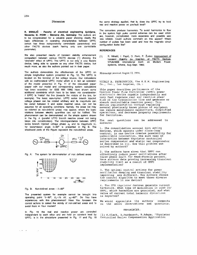
The authors demonstrate the effectiveness of the UPFC on simple longitudinal system presented in Fig. 12. The UPFC is located on the terminal of the voltage source. Our calculations with an mathematical UPFC model which is in fact an extension of the model presented in Fig. 11 of the discussed paper (paper with our model and corresponding system calculations has been submitted for IEEE WM 1995) have shown some additional constraints which have to be taken into consideration if UPFC is "inside" the line (towards the middle of the line, for example). The basic assumption, UPFC series branch injected voltage phasor can be rotated arbitrary and its magnitude can be varied between 0 and some maximal value, can not be assumed for all operating conditions. Namely, the areas (let they be referred as non-defined areas) may appear, where the basic relations between electric quantities can not be fulfilled. The phenomenon can be demonstrated on the simple system shown in the Fis. A (parallel UPFC branch reactive power not being taken into consideration). The interdependence between UPFC series branch injected voltage phase q+ and its magnitude U, for transmission angle 6=80° is presented in Fig B. The shadowed parts of the Figure represent the non-defined areas.
Fig. A: The system for demonstration of non defined areas
Fig. B:
The presented system for example cannot be brought into operating point "6=80°, UT=75 kV, q=6O0". Do You have experiences with this phenomenon? Have You foreseen the control actions to detect the vicinity of non-defined areas and to avoid them in Your models?
Non-defined areas - 6=80°
In Fig. 15 the real and reactive power are controlled independent to each other and are held on constant level by UPFC. Is in the simulations presented in Fig. 17 and Fig. 18
the same strategy applied, that is, does the UPFC try to hold real and reactive power on pre-fault level?
The converters produce harmonics. To avoid harmonics to flow in the system high pulse control schemes can be used which are, however, complicated, more expensive and possible also less reliable. Could authors comment on this aspect? Which number of pulses has been used and how the magnetic circuit configuration looks like?
REFERENCES
[l] R. MihaliE, I. PapiE, D. Povh, P. hnko: ImDrovement of transient Stabilitv bv Insertion of FACTS Devices, NTUNIEEE International Conf. on Modern Power. Systems, Athens, Aug.-Sept. 1993;
Manuscript received August 12, 1994.
VITALY A. FAYBISOVICH, The R.E.M. Engineering Co. , Inc. , Los Angeles, CA. : This paper describes performance of the Unified Power Flow Controller (UPFC) power electronic device capable independently and very fast regulate real and reactive power flow of the transmission line and generate or absorb controllable reactive power. This device implementation through replacing several previously known pieces of equipment can reduce maintenance expenditure, simplified operations, and decrease property requirements for facilities.
The next questions can be addressed to authors :
1. The consolidation several fast acting devices, which operate under close-loop control, in one device creates possibility for undesirable interaction. One such case of interaction between thyristor controlled series compensator and static var compensator is described in [l]. How this problem was solved by authors?
2. The authors have shown that UPFC can effectively reduce power oscillations after three-phase fault for Mead-Phoenix project. Have authors data proving increasing transient stability limit as a result of UPFC implementation?
3 . The optimal control actions for power oscillation damping and transient stability improving are different. How authors choose the control algorithm to meet those diverse requirements in one device?
4 . The GTO thyristor devices generate current harmonics. What type of modulation is used for UPFC, which harmonics are generated, and what value of current total harmonic distortion is expected?
We would appreciate the authors' comments on the above observations and questions.
REFERENCES.
[ l ] K.Clark, B.Fardanesh, R.Adapa, "Thyristor Controlled Series Compensation Application
1095
Study - Control Interaction Consideration", Paper # 94 SM 478-8 PWRD, Presented at the IEEE/PES 1994 Summer Meeting, San Francisco, California, July 1994.
Manuscript received August 22, 1994.
L. Gyugyi. C.D. Schauder, S.L. Williams, T.R. Rietman, D.R Torgerson, and A. Edris: The authors wish to thank the discussers for their comments and questions. Some of the questions allow us to further clarlfy the operation of the Unified Power Flow Controller (UPFC).
First the questions posed by Mr. Faybisovich are considered. His first question deals with the possible interactions between various functions of the UPFC. The first point to be made is that the p r h q function of the UPFC is power flow control which is accomplished by series, vectorial voltage injection. The UPFC may also provide (if required) a secondary function of voltage control accomplished by shunt reactive compensation. These two functions are controlled independently from each other. It could be considered that, for example, the reactive shunt compensation is controlled to regulate the bus voltage and the series voltage injection, changing the effective sending-end voltage seen by the line, controls the line current. The shunt compensation has relatively small effect on the line current. The line current variation caused by the series voltage injection is seen by the voltage regulator as a varying load. This is fairly typical control problem and the coordination of the two control loops is a well understood and usually manageable without undue difficulties.
Some clarification may be useful regarding the primary function of the UPFC, which is the control of real and reactive power flow in the line by series voltage injection. The significant point is that the control we developed for the UPFC does nor explicitly control the individual transmission parameters, such as transmission line voltage, impedance, and angle. Instead, it controls directly the real and reactive current components of the line by changing the magnitude and angle of the effective voltage at the (sending)-end of the line. This approach is inherently free of the ambiguity of separate parameter control (there is no unique solution for individual transmission line voltage, impedance, and angle for a desired line current vector, corresponding to the wanted real and reactive power flow) and it does not have the potential problems that the consolidation of several functions, each operated by an independent control loop may pose. More importantly, this control approach lends itself naturally to the optimization of transmission facilities: the transmitted real power is controllable over a wide range while the reactive power flow can be kept at a desired (minimum) level.
The second question is related to power oscillation damping. The paper does actually show two possible
approaches to handle power oscillations. The first one, illustrated in Figs. 14 and 15 of the paper, shows that a constant real and reactive power flow can be maintained in the line even if (either) one of the end-generators are in angular oscillation. In other words, the UPFC with a fired P and Q reference, would in effect decouple the sending- and receiving-ends. (Of course, in this case the UPFC would not aid the damping of the oscillating generator.) In the second approach, illustrated in Fig. 17 in connection with the Mead-Phoenics project, the UPFC is actively controlled damp power oscillations. This is achieved by modulating both the real and reactive power references so as to increase power transmission during the time intervals when acceleration of the "swinging" machine occurs, and decrease that when its deceleration takes place. Although that specific study was not concerned with transient stability, and thus no relevant data was generated, the inspection of Fig. 17 indicates, and other unrelated studies have verified, that the UPFC is able to increase transient stability limit more than any other power flow controller of the same rating.
The third question is related to control strategies used for transient stability improvement and power oscillation damping. The main point to see is that the UPFC, utilizing, in a general case, both its series voltage injection for real and reactive power flow control as well as its shunt reactive compensation for voltage control, has three reference inputs: real line power P, reactive line power Q, and terminal (bus) voltage V. Each of these three parameters can be modulated in order to maximize, minimize, or change in a prescribed manner the real power demand on the oscillating machine(s). Whatever strategy is selected for transient (first swing) stability improvement, it would be executed during and h e d i a t e l y following fault clearing. Subsequently, the modulation strategy considered optimum for power oscillation damping would be activated. The applicable modulation strategies are similar to those established for other type of power flow controllers and voltage regulators. However, the UPFC, controlling directly power flow and line voltage, would be able to execute most effectively their coordinated deployment for optimum results.
The fourth question is related to harmonic generation by the UPFC. The harmonic generation is, in general, a function of the power inverter circuit structure and the waveform construction technique employed. The inverter power circuit we have developed employs a structure and waveform construction technique which, without the use of filters, provides practically harmonic free operation. In other words, the output voltages and currents of the UPFC seen by the power system are practically sine waves.
In a second set of questions, Drs. Mihalic and Povh bring up an interesting subject related to a perceived operating constraint when the UPFC is connected to a relatively long transmission line segment at both its input and output
1096
terminals (e.g., the UPFC is operated at or near to the middle of the line). The discussers' own study indicates that, under this condition, the UPFC may not be able to inject the voltage vector, at all angular positions, with the desired maximum magnitude even if this magnitude is within the defined rating of the UPFC hardware.
We have been aware of this phenomenon and under appropriate system conditions we observed it with our TNA (Transient Network Analyzer) model. However, this perceived constraint is not an inherent property of the UPFC, but rather it is imposed by the particular transmission system or the selected location and operating mode of the UPFC within this system. Furthermore, the UPFC control, in our experience, automatically handles this condition.
The basic operating principle of the UPFC is to inject a voltage vector in series with the transmission line and thereby force the current in it so as to obtain the desired power transmission. It is a consequence of this principle that the power source providing this voltage vector exchanges varying amount of real and reactive power with the ac system as the magnitude and angle of the injected voltage is varied. The inverter in the UPFC executing the series voltage injection does internally generate the reactive power exchanged. However, the real power exchanged appears at the dc terminal of this inverter as a real power demand. In the particular circuit arrangement presently used to implement the UPFC, a shunt connected inverter is used to provide the real power demanded by the series inverter. Of course, since no other real power source is assumed, the series inverter draws the demanded real power from the ac system. In order to operate the UPFC with a given VA rating, without restriction, it is a fundamental requirement that the ac system is able to provide, at the "input" terminal of the UPFC, the real power exchanged through the series voltage injection. (This real power is, of course, part of the total power transmitted between the sending- and receiving-ends.) When the UPFC is moved towards the middle of a long line, and the injected voltage vector at, or near to, its maximum magnitude is rotated over the full 360°, the real and reactive power flow at particular angular positions in the line segment feeding the UPFC may be high enough to depress the line voltage to a level at which the demanded real power cannot be obtained from the ac system. At this point there would be a discrepancy between the real power demanded by the series inverter and that provided by the shunt inverter. As a result, the common dc voltage would decrease, forcing a decrease in the magnitude of the injected voltage vector until an equilibrium between the UPFC input power (Mwatts drawn by the shunt inverter) and output power (Mwatts exchanged by the series inverter) is established. If the shunt inverter is controlled to maintain the common dc capacitor voltage, the UPFC will automatically settle in an operating point at which the series voltage injection is sustainable.
Since the above situation is not inherent to the UPFC but system imposed, there are two simple ways to avoid it. One is to operate the UPFC from a strong enough bus which is consistent with the rating and the expected operating mode(s) of the UPFC. The other is to appropriately rate the shunt inverter and use its reactive compensation capability for voltage support at its Ynput" terminal, and in this way in effect establish a strong enough supply bus there.
The second question of Drs. Mihalic and Povh deals with power oscillation damping, specifically asking whether the same control strategy is used in the simulation results shown in Figs. 14 and 15, and those presented in Figs. 17 and 18. This question is essentially the same as the second question of Mr. Faybisovich, and the answer to that is already given above.
The last question is related to the implementation of the power inverters, the relationship between waveform quality (harmonics), circuit complexity, cost and reliability. This question really addresses design philosophy and our answer is given in general terms.
The first important point is that a given equipment rating (MVA) will require the same number of power semi- conductors independently of circuit configuration and pulse number, assuming large enough (transmission size) equipment, semiconductors with the same voltage and current ratings, sound engineering design, and similar design and operating margins. Consequently, the electronic complexity related to number of semiconductors, auxiliary components (snubber, etc.), gate drive circuits, fiber optical links, etc., as well as to mechanical parts (heat sinks, water pipes and connections, etc.) remain the same. The basic design considerations regarding the use of relatively high or relatively low pulse numbers are thus essentially related to non-electronic issues and trade-offs. These include:
Low pulse number design. Advantages: Requires simple magnetic structure, has relatively low output current and correspondingly small size bus bars. Because it inherently requires relatively large number of series-connected power semiconductors, implementation of device redundancy is relatively inexpensive. Disadvantages: The series connection of relatively large number of power semiconductors results in correspondingly increased current commutation, protection, and voltage insulation problems. Inherently high harmonic generation requires either large filters or pulse- width modulation (PWM) with smaller filter(s). Harmonic currents may reduce power semiconductor utilization (requiring an increase in the number of devices), PWM increases operating losses. Partial availability (in case of inverter failure) is not practical.
High pulse number design. Advantages: Harmonic generation is inherently low, requiring no filters. The switching frequency of the semiconductors can be kept at
1097
a practical high power UPFC. We have firmly decided on a multi-pulse implementation that requires no output filters. Our experience with a 100 MVA, 48-pulse inverter, which has gone through final testing and presently being installed at the Sullivan substation of the TVA (Tennessee Valley Authority) transmission network to provide & 100 MVAR reactive compensation, has so far fulfilled all our expectations.
the fundamental system frequency (60 or 50 Hz) to minimize operating losses. The harmonicifree, sinusoidal inverter current allows full utilization of power semiconductors. The number of power semiconductors in series is relatively small (5-20), the corresponding current commutation, protection and insulation problems are more readily manageable. Depending on the implementation, the multi-pulse inverter structure can be designed for partial availability. Disadvantages: Requires more complex magnetic structure. For relatively small number of series- connected power semiconductors, device redundancy requirement may increase cost.
With the above, general design considerations we have carried out a detailed evaluation regarding the implementation of the inverter structure we plan to use in
In the EM" (and subsequent TNA) simulations described in the paper both the series and shunt inverters have 48- pulse structure. The magnetic circuit is proprietary and cannot be revealed this time.