Provides one channel to convert 10BASE-T/ 100BASE-TX to 100BASE-FX media. Use as a standalone device or with a standard 19" rackmount chassis. 10/100BASE-TX to 100BASE-FX Media Converter April 2010 LBMC300-MMST LBMC300-MMSC Order toll-free in the U.S.: Call 877-877-BBOX (outside U.S. call 724-746-5500) • FREE technical support 24 hours a day, 7 days a week: Call 724-746-5500 or fax 724-746-0746 • Mailing address: Black Box Corporation, 1000 Park Drive, Lawrence, PA 15055-1018 • Web site: www.blackbox.com • E-mail: [email protected]Customer Support Information
Transcript
BLACK BOX® Provides one channel to convert 10BASE-T/
100BASE-TX to 100BASE-FX media.
Use as a standalone device or with a standard 19" rackmount chassis.
10/100BASE-TX to 100BASE-FX Media Converter
April 2010LBMC300-MMSTLBMC300-MMSC
Order toll-free in the U.S.: Call 877-877-BBOX (outside U.S. call 724-746-5500) • FREE technical support 24 hours a day, 7 days a week: Call 724-746-5500 or fax 724-746-0746 • Mailing address: Black Box Corporation, 1000 Park Drive, Lawrence, PA 15055-1018 •Web site: www.blackbox.com • E-mail: [email protected]
Customer Support
Information
724-746-5500 | blackbox.com Page 2
10/100BASE-TX to 100BASE-FX Media Converter
FEDERAL COMMUNICATIONS COMMISSION AND INDUSTRY CANADA RADIO FREQUENCY INTERFERENCE
STATEMENTS
This equipment generates, uses, and can radiate radio-frequency energy, and if not installed and used properly, that is, in strict accordance with the manufacturer’s instructions, may cause inter ference to radio communication. It has been tested and found to comply with the limits for a Class A computing device in accordance with the specifications in Subpart B of Part 15 of FCC rules, which are designed to provide reasonable protection against such interference when the equipment is operated in a commercial environment. Operation of this equipment in a residen-tial area is likely to cause interference, in which case the user at his own expense will be required to take whatever measures may be necessary to correct the interference.
Changes or modifications not expressly approved by the party responsible for compliance could void the user’s authority to operate the equipment.
This digital apparatus does not exceed the Class A limits for radio noise emis sion from digital apparatus set out in the Radio Interference Regulation of Industry Canada.
Le présent appareil numérique n’émet pas de bruits radioélectriques dépassant les limites applicables aux appareils numériques de classe A prescrites dans le Règlement sur le brouillage radioélectrique publié par Industrie Canada.
1. Todas las instrucciones de seguridad y operación deberán ser leídas antes de que el aparato eléctrico sea operado.
724-746-5500 | blackbox.com Page 3
NOM Statement
2. Las instrucciones de seguridad y operación deberán ser guardadas para referencia futura.
3. Todas las advertencias en el aparato eléctrico y en sus instrucciones de operación deben ser respetadas.
4. Todas las instrucciones de operación y uso deben ser seguidas.
5. El aparato eléctrico no deberá ser usado cerca del agua—por ejemplo, cerca de la tina de baño, lavabo, sótano mojado o cerca de una alberca, etc.
6. El aparato eléctrico debe ser usado únicamente con carritos o pedestales que sean recomendados por el fabricante.
7. El aparato eléctrico debe ser montado a la pared o al techo sólo como sea recomendado por el fabricante.
8. Servicio—El usuario no debe intentar dar servicio al equipo eléctrico más allá a lo descrito en las instrucciones de operación. Todo otro servicio deberá ser referido a personal de servicio calificado.
9. El aparato eléctrico debe ser situado de tal manera que su posición no interfiera su uso. La colocación del aparato eléctrico sobre una cama, sofá, alfombra o superficie similar puede bloquea la ventilación, no se debe colocar en libreros o gabinetes que impidan el flujo de aire por los orificios de ventilación.
10. El equipo eléctrico deber ser situado fuera del alcance de fuentes de calor como radiadores, registros de calor, estufas u otros aparatos (incluyendo amplificadores) que producen calor.
11. El aparato eléctrico deberá ser connectado a una fuente de poder sólo del tipo descrito en el instructivo de operación, o como se indique en el aparato.
12. Precaución debe ser tomada de tal manera que la tierra fisica y la polarización del equipo no sea eliminada.
13. Los cables de la fuente de poder deben ser guiados de tal manera que no sean pisados ni pellizcados por objetos colocados sobre o contra ellos, poniendo particular atención a los contactos y receptáculos donde salen del aparato.
724-746-5500 | blackbox.com Page 4
10/100BASE-TX to 100BASE-FX Media Converter
14. El equipo eléctrico debe ser limpiado únicamente de acuerdo a las recomendaciones del fabricante.
15. En caso de existir, una antena externa deberá ser localizada lejos de las lineas de energia.
16. El cable de corriente deberá ser desconectado del cuando el equipo no sea usado por un largo periodo de tiempo.
17. Cuidado debe ser tomado de tal manera que objectos liquidos no sean derramados sobre la cubierta u orificios de ventilación.
18. Servicio por personal calificado deberá ser provisto cuando:
A: El cable de poder o el contacto ha sido dañado; u
B: Objectos han caído o líquido ha sido derramado dentro del aparato; o
C: El aparato ha sido expuesto a la lluvia; o
D: El aparato parece no operar normalmente o muestra un cambio en su desempeño; o
E: El aparato ha sido tirado o su cubierta ha sido dañada.
724-746-5500 | blackbox.com Page 5
Trademarks Used in this Manual
Trademarks Used in this ManualBlack Box and the Double Diamond logo are registered trademarks of BB Technologies, Inc.
UL is a registered trademark of Underwriters Laboratories Inc.
Any other trademarks mentioned in this manual are acknowledged to be the property of the trademark owners.
724-746-5500 | blackbox.com Page 6
10/100BASE-TX to 100BASE-FX Media Converter
Table of ContentsChapter Page
1. Specifications .............................................................................................7 2. Overview .................................................................................................8 2.1 Introduction......................................................................................8 2.2 Features ............................................................................................8 2.3 What’s Included ...............................................................................9 2.4 Hardware Description ......................................................................9 2.4.1 Front Panel ...........................................................................9 2.4.2 Back Panel .........................................................................10
4. LED Indicators...........................................................................................13
5. Link Fault Passthrough .............................................................................14
6. Imstallation ...............................................................................................15 6.1 Selecting a Site for the Equipment ................................................15 6.2 Connecting to Power .....................................................................15 6.3 Installing in a Chassis .....................................................................15
724-746-5500 | blackbox.com Page 7
Chapter 1: Specifications
1. Specifications
Emissions: FCC Part 15 Class A, CE Mark
Fixed Ports: (1) TX port, (1) FX port
Forwarding Rate: 14,880 pps for 10 Mbps; 148,800 pps for 100 Mbps
Safety: UL® 60950-1
Speed: 10/20 Mbps for half-/full-duplex 10BASE-T; 100/200 Mbps for half-/full-duplex 100BASE-TX/FX
Standards: IEEE 802.3 10BASE-T, IEEE 802.3u 100BASE-TX and 100BASE-FX
Switching Method: Store and forward
User Controls: (1) 6-position DIP switch
Connectors: LBMC300-MMST: (1) pair of ST, (1) RJ-45, (1) barrel connector for power; LBMC300-MMSC: (1) pair of SC, (1) RJ-45, (1) barrel connector for power
Indicators: Per unit: (2) LEDs: Power, 100 Mbps; Per port: (2) LEDs: LNK/ACT, FDX/COL
Operating Temperature: 32 to 113° F (0 to 45° C)
Humidity Tolerance: 5 to 95%, noncondensing
Power: External power adapter 0.16 A at 12 VDC; Consumption: 1.9 W maximum
Size: 0.9"H x 3.2"W x 4.3"D (2.4 x 8 x 10.9 cm)
724-746-5500 | blackbox.com Page 8
10/100BASE-TX to 100BASE-FX Media Converter
2. Overview
2.1 IntroductionLBMC300-MMST and LBMC300-MMSC converters provide one channel for media conversion between 10BASE-T/100BASE-TX and 100BASE-FX. They can be used as a standalone device or with a standard 19” chassis as shown in Figure 2-1.
An LBMC300-MMST or LBMC300-MMSC media converter provides one TX port and one FX port. For the FX port, you can use multimode fiber cable with an SC or ST connector, depending on the model. The TX port uses one RJ-45 connector and autosenses the 10-/100-Mbps speed.
Port settings are easy via a DIP (Dual Inline Package) switch on the rear panel of the module.
Figure 2-1. Converters installed in a rack.
NOTE: The rack (part number LB300A-RACK) is available separately.
2.2 Features• Converts one channel between 10BASE-T/100BASE-TX and 100BASE-FX media
• Fiber media can be multimode fiber using SC or ST connectors
• Autonegotiation of speed and duplex mode on TX port
• Auto MDI-X on TX port
• One DIP switch for configuring link-fault-passthrough, fixed speed, and half/full duplex
• 2048 MAC addresses, 768K bits buffer memory
• Store-and-forward mechanism
724-746-5500 | blackbox.com Page 9
Chapter 2: Overview
• Non-blocking full wire-speed forwarding rate
• Support broadcast storm filtering
• Backpressure and IEEE 802.3x compliant flow control
• Front-panel status LEDs
• External AC to DC power adapter
• Used as a standalone device or with a chassis
• Hot-swappable when used with a chassis
2.3 What’s IncludedYour package should contain the following items. If anything is missing or damaged, contact Black Box Technical Support at 724-746-5500 or [email protected].
• Media Converter
• AC to DC power adapter
• This user’s manual
2.4 Hardware Description2.4.1 Front PanelFigure 2-2 shows the front panel of the media converter. Table 2-1 describes its components.
3 2 1
Figure 2-2. Front panel.
724-746-5500 | blackbox.com Page 10
10/100BASE-TX to 100BASE-FX Media Converter
Table 2-1. Front-panel components.
Number Component Description 1 SC or ST connector Fiber link
2 LEDs See Table 4-1 in Chapter 4.
3 RJ-45 connector Twisted-pair link
2.4.2 Back PanelFigure 2-3 shows the back panel of the media converter. Table 2-2 describes its components.
4 5
Figure 2-3. Back panel.
Table 2-2. Back-panel components.
Number Component Description 4 6-position DIP switch Configuration
5 Barrel connector Power
724-746-5500 | blackbox.com Page 11
Chapter 3: DIP Switch Settings
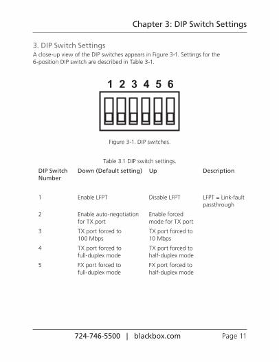
3. DIP Switch SettingsA close-up view of the DIP switches appears in Figure 3-1. Settings for the 6-position DIP switch are described in Table 3-1.
Figure 3-1. DIP switches.
Table 3.1 DIP switch settings.
DIP Switch Down (Default setting) Up Description Number
2 Enable auto-negotiation Enable forced for TX port mode for TX port
3 TX port forced to TX port forced to 100 Mbps 10 Mbps
4 TX port forced to TX port forced to full-duplex mode half-duplex mode
5 FX port forced to FX port forced to full-duplex mode half-duplex mode
724-746-5500 | blackbox.com Page 12
10/100BASE-TX to 100BASE-FX Media Converter
To set the DIP switches:
1. First, disconnect the converter from the power. Then toggle Pin 2 of the DIP switch to the up position to enable the forced mode for TX port.
NOTE: Pin 2 must be toggled up before setting speed and duplex mode manually.
2. Toggle down Pin 3 to force the TX port at the speed of 100 Mbps. Or toggle up Pin 3 for 10-Mbps speed.
3. Toggle down Pin 4 to force the TX port at full-duplex mode. Or toggle up Pin 4 for half-duplex mode.
4. Toggle down Pin 5 to force the FX port at full-duplex mode. Or toggle up Pin 5 for half duplex mode.
5. Toggle up Pin 1 to disable the link-fault-pass-through.
6. Connect the converter to the power again. The new setting will then take effect.
724-746-5500 | blackbox.com Page 13
Chapter 4: LED Indicators
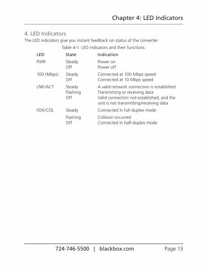
4. LED IndicatorsThe LED indicators give you instant feedback on status of the converter.
Table 4-1. LED indicators and their functions.
LED State Indication
PWR Steady Power on Off Power off
100 (Mbps) Steady Connected at 100 Mbps speed Off Connected at 10 Mbps speed
LNK/ACT Steady A valid network connection is established Flashing Transmitting or receiving data Off Valid connection not established, and the
unit is not transmitting/receiving data
FDX/COL Steady Connected in full-duplex mode
Flashing Collision occurred Off Connected in half-duplex mode
724-746-5500 | blackbox.com Page 14
10/100BASE-TX to 100BASE-FX Media Converter
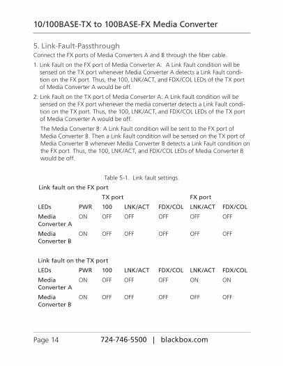
5. Link-Fault-PassthroughConnect the FX ports of Media Converters A and B through the fiber cable.
1. Link Fault on the FX port of Media Converter A: A Link Fault condition will be sensed on the TX port whenever Media Converter A detects a Link Fault condi-tion on the FX port. Thus, the 100, LNK/ACT, and FDX/COL LEDs of the TX port of Media Converter A would be off.
2. Link Fault on the TX port of Media Converter A: A Link Fault condition will be sensed on the FX port whenever the media converter detects a Link Fault condi-tion on the TX port. Thus, the 100, LNK/ACT, and FDX/COL LEDs of the TX port of Media Converter A would be off.
The Media Converter B: A Link Fault condition will be sent to the FX port of Media Converter B. Then a Link Fault condition will be sensed on the TX port of Media Converter B whenever Media Converter B detects a Link Fault condition on the FX port. Thus, the 100, LNK/ACT, and FDX/COL LEDs of Media Converter B would be off.
Table 5-1. Link fault settings.
Link fault on the FX port
TX port FX port
LEDs PWR 100 LNK/ACT FDX/COL LNK/ACT FDX/COL
Media ON OFF OFF OFF OFF OFF Converter A
Media ON OFF OFF OFF OFF OFF Converter B
Link fault on the TX port
LEDs PWR 100 LNK/ACT FDX/COL LNK/ACT FDX/COL
Media ON OFF OFF OFF ON ON Converter A
Media ON OFF OFF OFF OFF OFF Converter B
724-746-5500 | blackbox.com Page 15
Chapter 6: Installation
6. InstallationThis chapter gives step-by-step installation instructions for the converter.
6.1 Selecting a Site for the EquipmentAs with any electric device, you should place the equipment where it will not be subjected to extreme temperatures, humidity, or electromagnetic interference. Specifically, the site you select should meet the following requirements:
• The ambient temperature should be between 32 and 113 degrees Fahrenheit (0 to 45 degrees Celsius).
• The relative humidity should be less than 95 percent, noncondensing.
• Surrounding electrical devices should not exceed the electromagnetic field (RFC) standards for IEC 8013, Level 2 (3V/M) field strength.
• Make sure that the equipment receives adequate ventilation. Do not block the ventilation holes on each side of the equipment.
• The power outlet should be within 6 feet (1.8 m) of the converter.
6.2 Connecting to PowerThis Converter is a plug-and-play device.
Connect the supplied AC to DC power adapter to the receptacle on the rear panel of the converter, and then attach the plug into a standard AC outlet.
6.3 Installing in a ChassisLBMC300-MMST and LBMC300-MMSC fit into any of the expansion slots on the compatible chassis, LB300A-RACK. Follow the steps described below.
First, install the converter onto a carrier supplied with the chassis:
Step 1: Unscrew the carrier from the desired expansion slot on the chassis.
Step 2: Fit the converter onto the carrier.
Step 3: When the converter is completely seated onto the carrier, insert the carrier to the guide rails of the expansion slot.
Step 4: Carefully slide in the carrier until it is fully and firmly fit in the chassis. Fasten the screws onto the carrier.
NOTE: Never insert any converter into the chassis directly without using the supplied carriers. The carriers enable you to place the converters securely and consistently without damaging them.